


Languages
Pages
Legal


SERVICE MANUAL STARTER Portable Meter
ST300
ST300C
ST300D
ST400D
Ohaus Corporation, 7 Campus Drive, Suite 310, Parsippany, NJ 07054 (973) 377-9000

SERVICE MANUAL
STARTER Portable Meter
ST300
ST300C
ST300D
ST400D
The information contained in this manual is believed to be accurate at the time of publication, but Ohaus Corporation assumes no liability arising from the use or misuse of this material. Reproduction of this material is strictly prohibited. Material in this manual is subject to change. © Copyright 2015 Ohaus Corporation, all rights reserved. TM Registered trademark of Ohaus Corporation.

TABLE OF CONTENTS
Ohaus Corporation www.ohaus.com i Starter 2100/3100/3100C Service Manual
Page No.
CHAPTER 1 GETTING STARTED 1.1 Introduction ..............................................................................................................1-1 1.2 Definition of Signal Words and Symbol ....................................................................1-1 1.3 Safety Precaution .....................................................................................................1-2 1.4 Service Facilities ......................................................................................................1-2 1.5 Tools and Test Equipment Required ........................................................................1-2 1.6 Specifications ...........................................................................................................1-3 1.7 Meter Operation Starter 300 .....................................................................................1-5
1.7.1 Overview of the Controls ...................................................................................1-5 1.8 Meter Operation Starter 300C ..................................................................................1-7
1.8.1 Overview of the Controls ...................................................................................1-7 1.9 Meter Operation Starter 300D ..................................................................................1-9
1.9.1 Overview of the Controls ...................................................................................1-9 1.10 Meter Operation Starter 400D ................................................................................ 1-11 1.10.1 Overview of the Controls ................................................................................. 1-11
CHAPTER 2 MAINTENANCE PROCEDURES
2.1 Preventive Maintenance ...........................................................................................2-1 2.2 Service Strategy .......................................................................................................2-1 2.3 Opening the Meter ...................................................................................................2-1
2.2.1 Separating the Top and Bottom Housings .........................................................2-1 2.4 Removing/Replacing the Main Printed Circuit Board (PCB) .....................................2-2 2.5 Replacing ST400D Internal Battery ..........................................................................2-4
CHAPTER 3 RESET TO FACTORY SETTINGS 3.1. Recover Factory Settings .........................................................................................3-1 3.2 Error Message .........................................................................................................3-2 CHAPTER 4 DRAWINGS AND PARTS LISTS
4-1 Starter ST300, ST300C and ST300D: Housing & Internal Parts ...............................4-2 4-2 Starter ST400D: Housing & Internal Parts ................................................................4-3
LIST OF TABLES TABLE NO. TITLE Page No.
1-1 Specifications ......................................................................................................1-2 1-2 Starter 300 Controls Functions ............................................................................1-6 1-3 Starter 300C Controls Functions ..........................................................................1-8 1-4 Starter 300D Controls Functions ........................................................................ 1-10 1-5 Starter 400D Controls Functions ........................................................................ 1-12 3-1 Error Message ST300 ..........................................................................................3-2 3-2 Error Message ST300C .......................................................................................3-2 3-3 Error Message ST300D .......................................................................................3-3 3-4 Error Message ST400D .......................................................................................3-3 4-1 Housing & Internal Parts ST300, ST300C & ST300D ..........................................4-2 4-2 Housing & Internal Parts ST400D ........................................................................4-3

TABLE OF CONTENTS
Valor™ 7000 Series Service Manual ii Ohaus Corporation www.ohaus.com
LIST OF ILLUSTRATIONS FIGURE NO. TITLE
1-1 Starter 300 Display ..............................................................................................1-5 1-2 Starter 300C Display ............................................................................................1-7 1-3 Starter 300D Display ............................................................................................1-9 1-4 Starter 400D Display .......................................................................................... 1-11 2-1 Screws securing Top Housing .............................................................................2-2 2-2 Main Printed Curcuit Board ..................................................................................2-2 2-3 Battery Spring ......................................................................................................2-3 2-4 Replacing Main PCBA .........................................................................................2-3 2-5 ST400D Internal Battery Location ........................................................................2-4 3-1 ST400D Factory Default Screen ..........................................................................3-1 4-1 Housing & Internal Parts ST300, ST300C & ST300D ..........................................4-2 4-2 Housing & Internal Parts ST400D ........................................................................4-3
CHAPTER 1 GETTING STARTED
Starter Series Portable Meter Service Manual 1-1 Ohaus Corporation www.ohaus.com
1.1 INTRODUCTION
This service manual contains the information needed to perform routine maintenance and service on the Ohaus Starter ST300, ST300C, ST300D and ST400D Series portable meters. Familiarity with the meter’s Instruction Manual is assumed. The contents of this manual are contained in five chapters:
Chapter 1 Getting Started – Contains information on service facilities, tools and test equipment, specifications, and the mechanical and electronic functions of the meter.
Chapter 2 Maintenance Procedures – Contains preventive maintenance procedures and disassembly, repair and replacement procedures.
Chapter 3 Reset to factory settings – Explains procedures for resetting the meter to factory default settings.
Chapter 4 Drawings and Parts Lists – Contains exploded views of Starter ST300,
St300C, ST300D and ST400D portable meters identifying all serviceable components.
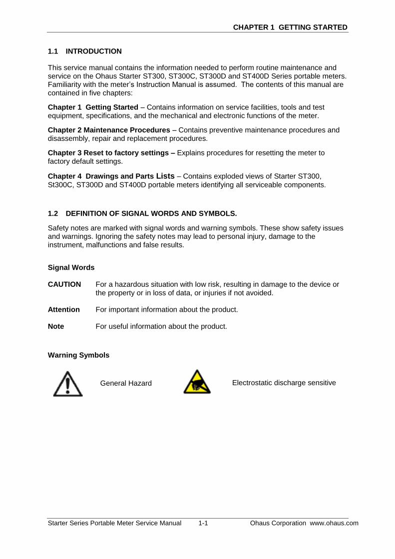
1.2 DEFINITION OF SIGNAL WORDS AND SYMBOLS.
Safety notes are marked with signal words and warning symbols. These show safety issues and warnings. Ignoring the safety notes may lead to personal injury, damage to the instrument, malfunctions and false results.
Signal Words CAUTION For a hazardous situation with low risk, resulting in damage to the device or
the property or in loss of data, or injuries if not avoided. Attention For important information about the product. Note For useful information about the product.
Warning Symbols
General Hazard Electrostatic discharge sensitive
CHAPTER 1 GETTING STARTED
Ohaus Corporation www.ohaus.com 1-2 Starter Series Portable Meter Service Manual
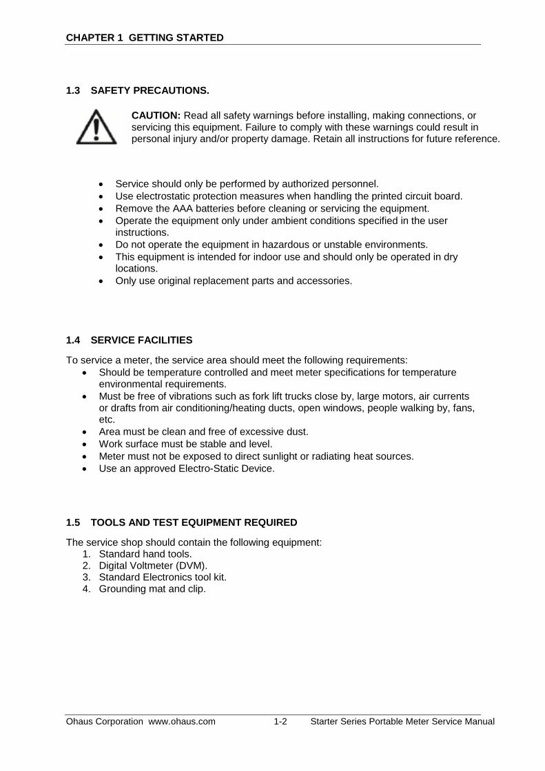
1.3 SAFETY PRECAUTIONS.
Service should only be performed by authorized personnel.
Use electrostatic protection measures when handling the printed circuit board.
Remove the AAA batteries before cleaning or servicing the equipment.
Operate the equipment only under ambient conditions specified in the user instructions.
Do not operate the equipment in hazardous or unstable environments.
This equipment is intended for indoor use and should only be operated in dry locations.
Only use original replacement parts and accessories.
1.4 SERVICE FACILITIES
To service a meter, the service area should meet the following requirements:
Should be temperature controlled and meet meter specifications for temperature environmental requirements.
Must be free of vibrations such as fork lift trucks close by, large motors, air currents or drafts from air conditioning/heating ducts, open windows, people walking by, fans, etc.
Area must be clean and free of excessive dust.
Work surface must be stable and level.
Meter must not be exposed to direct sunlight or radiating heat sources.
Use an approved Electro-Static Device.
1.5 TOOLS AND TEST EQUIPMENT REQUIRED
The service shop should contain the following equipment: 1. Standard hand tools. 2. Digital Voltmeter (DVM). 3. Standard Electronics tool kit. 4. Grounding mat and clip.
CAUTION: Read all safety warnings before installing, making connections, or servicing this equipment. Failure to comply with these warnings could result in personal injury and/or property damage. Retain all instructions for future reference.

CHAPTER 1 GETTING STARTED
Starter Series Portable Meter Service Manual 1-3 Ohaus Corporation www.ohaus.com
1.6 SPECIFICATIONS
Complete specifications for the Ohaus Starter portable meters are listed in Table 1-1. When a meter has been serviced, it must meet the specifications listed in the table. Before servicing the meter, determine what specifications are not met.
TABLE 1-1. SPECIFICATIONS
…
– …
° … °
μ …
…
° … °°
°°
°
±
±
± °
±
± °
± ± °
× × ×
Ω
Ω Ω
° …
°
°

CHAPTER 1 GETTING STARTED
Ohaus Corporation www.ohaus.com 1-4 Starter Series Portable Meter Service Manual
Model ST400D
Measurement Range
% 0.0 to 200.0%
mg/L 0.00 to 20.00mg/L (ppm)
Temp. 0 to 50 °C
Measurement Resolution
% 0.1%
mg/L 0.01 mg/L
Temp. 0.1 °C
Accuracy
± 0.2 mg/L (<8 mg/L)
± 0.3 mg/L (8 to 20 mg/L);
± 0.3 °C
Barometric
Range 50.0 to 115.0 kPa
Resolution 0.1 kPa
Accuracy 1.5 kPa
Temp compensation ATC
Salinity compensation 0.0 to 40.0 ppt
Calibration 1 point or 2 points
Memory 99 sets, last calibration data
Power 4 x AAA(LR03) batteries, 12 hrs
Size/Weight 90 W x 150 D x 35 H mm
Weight 0.16kg
Display liquid crystal
IP rating IP54
T input Mini-Din
Materials ABS
CHAPTER 1 GETTING STARTED
Starter Series Portable Meter Service Manual 1-5 Ohaus Corporation www.ohaus.com
1.7 METER OPERATION – STARTER ST300
This section contains information on the basic operation of the Starter ST300 meter.
1.7.1 OVERVIEW OF THE CONTROLS
Displays
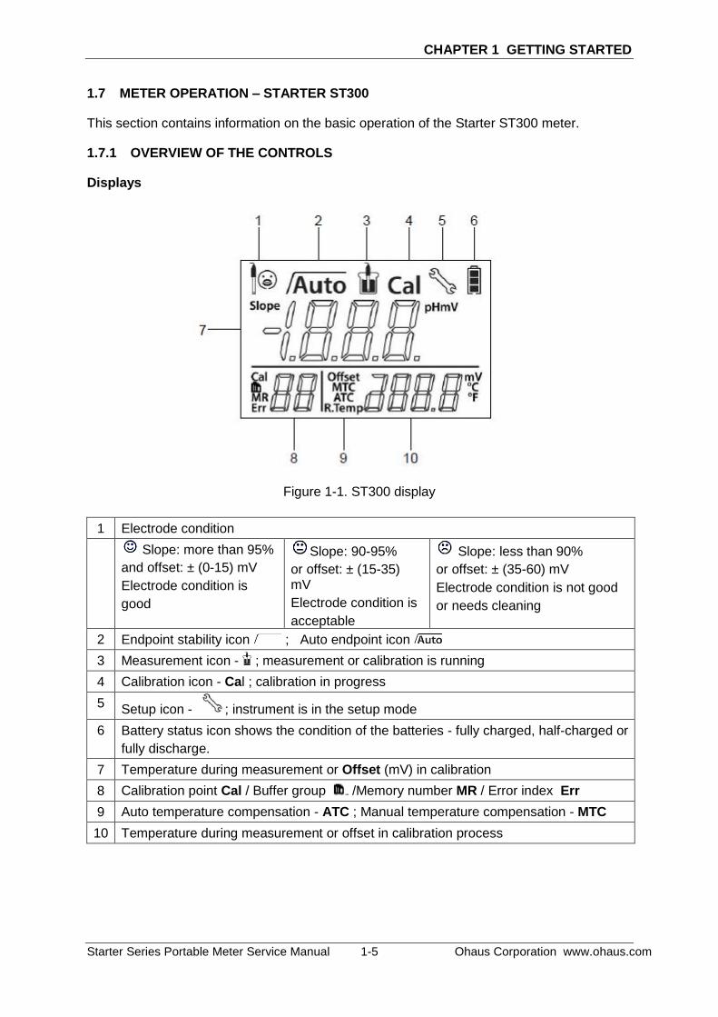
Figure 1-1. ST300 display
1 Electrode condition
Slope: more than 95%
and offset: ± (0-15) mV
Electrode condition is
good
Slope: 90-95%
or offset: ± (15-35) mV
Electrode condition is
acceptable
Slope: less than 90%
or offset: ± (35-60) mV
Electrode condition is not good
or needs cleaning
2 Endpoint stability icon ; Auto endpoint icon
3 Measurement icon - ; measurement or calibration is running
4 Calibration icon - Cal ; calibration in progress
5 Setup icon - ; instrument is in the setup mode
6 Battery status icon shows the condition of the batteries - fully charged, half-charged or
fully discharge.
7 Temperature during measurement or Offset (mV) in calibration
8 Calibration point Cal / Buffer group /Memory number MR / Error index Err
9 Auto temperature compensation - ATC ; Manual temperature compensation - MTC
10 Temperature during measurement or offset in calibration process
CHAPTER 1 GETTING STARTED
Ohaus Corporation www.ohaus.com 1-6 Starter Series Portable Meter Service Manual
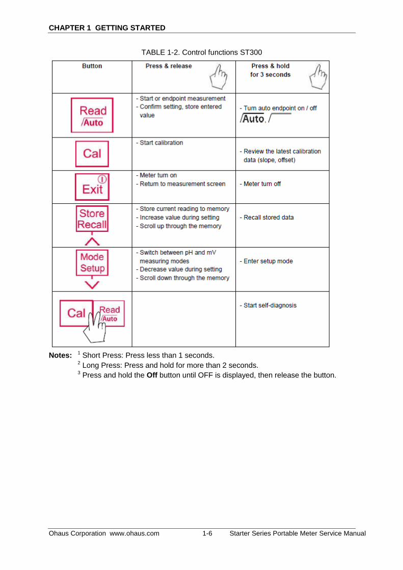
TABLE 1-2. Control functions ST300
Notes: 1 Short Press: Press less than 1 seconds.
2 Long Press: Press and hold for more than 2 seconds.
3 Press and hold the Off button until OFF is displayed, then release the button.
CHAPTER 1 GETTING STARTED
Starter Series Portable Meter Service Manual 1-7 Ohaus Corporation www.ohaus.com
1.8 METER OPERATION – ST300C
This section contains information on the basic operation of the ST300C meter.
1.8.1 OVERVIEW OF THE CONTROLS
Displays
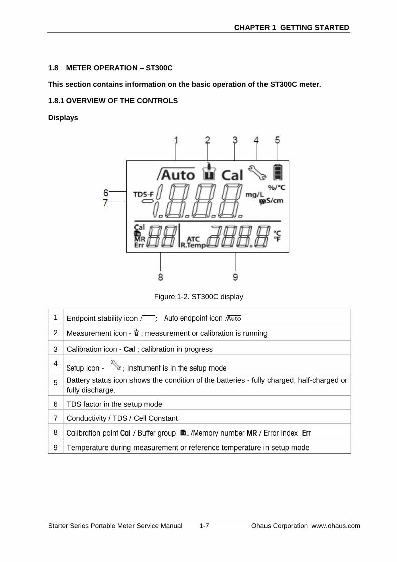
Figure 1-2. ST300C display
1 Endpoint stability icon ; Auto endpoint icon
2 Measurement icon - ; measurement or calibration is running
3 Calibration icon - Cal ; calibration in progress
4 Setup icon - ; instrument is in the setup mode
5 Battery status icon shows the condition of the batteries - fully charged, half-charged or
fully discharge.
6 TDS factor in the setup mode
7 Conductivity / TDS / Cell Constant
8 Calibration point Cal / Buffer group /Memory number MR / Error index Err
9 Temperature during measurement or reference temperature in setup mode

CHAPTER 1 GETTING STARTED
Ohaus Corporation www.ohaus.com 1-8 Starter Series Portable Meter Service Manual
TABLE 1-3. Control functions ST300C
Notes: 1 Short Press: Press less than 1 seconds.
2 Long Press: Press and hold for more than 2 seconds.
3 Press and hold the Off button until OFF is displayed, then release the button.

CHAPTER 1 GETTING STARTED
Starter Series Portable Meter Service Manual 1-9 Ohaus Corporation www.ohaus.com
1.9 METER OPERATION – ST300D
This section contains information on the basic operation of the Starter 3100C meter.
1.9.1 OVERVIEW OF THE CONTROLS
Displays
Figure 1-3. ST300D display
1 Electrode condition
Slope: 80-125% Electrode condition is very good
Slope: 60-80% Electrode condition is not so good, needs attention or cleaning
2 Displays when manual endpoint, need to press button-Read to lock the reading, means auto endpoint mode, meter judges the endpoint (reading is stable) and locks the reading automatically.
3 Measurement icon - ; measurement or calibration is running
4 Calibration icon - Cal ; calibration in progress
5 Setup icon - instrument is in the setup mode
6 Power always on icon - Meter will not automatically turn off after 10 minutes no operation.
7 Battery status icon - fully charged, half-charged or fully discharged
8 ppm, mg/L or % for DO reading or calibration; mbar, hPa or mmHg for pressure entry; ppt for salinity entry
9 Calibration point Cal / Buffer group /Memory number MR / Error index Err 10 Auto temperature compensation - ATC ; Manual temperature compensation -
MTC
11 Temperature during measurement or reference temperature in setup mode

CHAPTER 1 GETTING STARTED
Ohaus Corporation www.ohaus.com 1-10 Starter Series Portable Meter Service Manual
TABLE 1-4. Control functions ST300D

CHAPTER 1 GETTING STARTED
Starter Series Portable Meter Service Manual 1-11 Ohaus Corporation www.ohaus.com
1.10 METER OPERATION – ST400D
This section contains information on the basic operation of the Starter 3100C meter.
1.10.1 OVERVIEW OF THE CONTROLS
Displays
Figure 1-4. ST400D display
1 Time: HH:MM:SS
2 Date: YYYY-MM-DD
3
calibration data: |K-
1|≤0.3 and |B|<0.1
Probe condition is very good
calibration data: 0.3≤|K-
1|≤0.4 and |B| <0.1
Probe condition is acceptable. 4 Measurement icon - measurement (calibration) is running
5 Calibration icon - calibration is running
6 Power state icon, include power always on icon , means meter
will not automatically turn off; and auto-off icon which means after 10 minutes no operation meter will turn off(see 4.4); power state icon position is at the top-left of the battery status icon.
7 Battery status icon – the charged status of the battery 8 DO reading: mg/L and %
9 Temperature during measurement or in calibration process
10 Barometric pressure during measurement or in calibration process
11 Data log: memory number
12 ppt for salinity entry

CHAPTER 1 GETTING STARTED
Ohaus Corporation www.ohaus.com 1-12 Starter Series Portable Meter Service Manual
TABLE 1-5. Control functions ST400D
Button Press & release
Press & hold
for 2 seconds
- Start or endpoint measurement
(manual endpoint mode)
- Confirm setting, confirm entered
value for setting
- switch between auto endpoint
and manual endpoint mode
- Start calibration - Review the latest calibration
data
- Meter turn on
- Back to measurement screen
- Meter turn off
- Store current reading to memory
- Increase value during setting
- Scroll up through the memory
- Recall stored data
- Enter setup screen
- Scroll down through the memory
- Reset factory setting
CHAPTER 2 MAINTENANCE PROCEDURES
Starter Series Portable Meter Service Manual 2-1 Ohaus Corporation www.ohaus.com
2.1 PREVENTIVE MAINTENANCE
ATTENTION: remove the AAA batteries before cleaning the meter.
Ohaus meters are precision instruments and should be carefully handled, stored in a clean, dry, dust-free area, and cleaned periodically.
The meter housing may be cleaned with a cloth dampened with a mild detergent if necessary. Do not use solvents, chemicals, alcohol, ammonia or abrasives to clean the housing or control panel.
2.2 SERVICE STRATEGY
All parts of the Starter 300, 300C, 300D and 400 are designed to be replaced rather than repaired. This includes the Main Printed Circuit Board (PCB). For an illustrated list of replaceable parts, see Chapter 5.
2.3 OPENING THE METER
Use these procedures in order to replace the Printed Circuit Board and CR2032 battery, if applicable.
2.3.1 Separating the Top and Bottom Housings
Common hand tools are sufficient to disassemble the Starter 300, 300C, 300D and 400 meter.
1. Remove any electrodes connected to the portable meter.
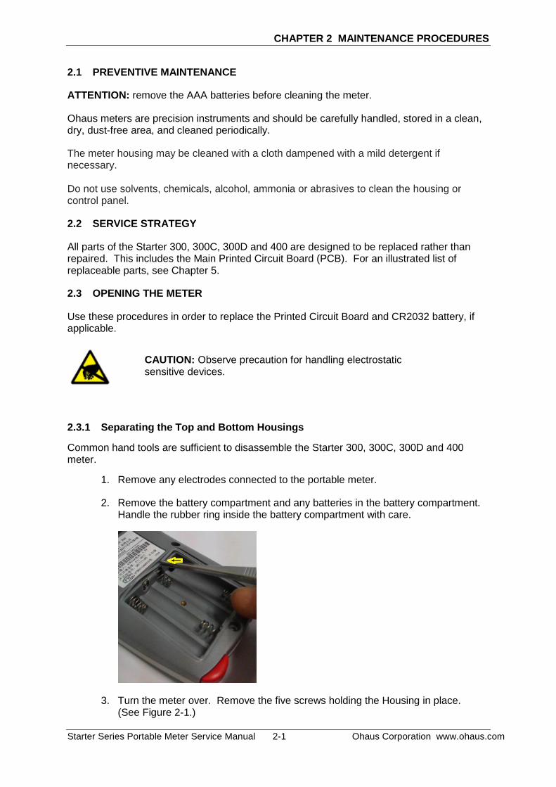
2. Remove the battery compartment and any batteries in the battery compartment. Handle the rubber ring inside the battery compartment with care.
3. Turn the meter over. Remove the five screws holding the Housing in place. (See Figure 2-1.)
CAUTION: Observe precaution for handling electrostatic sensitive devices.

CHAPTER 2 MAINTENANCE PROCEDURES
Ohaus Corporation www.ohaus.com 2-2 Starter Series Portable Meter Service Manual
4. Before separating the top
housing from the bottom housing remove the keypad membrane connector which connected to the main PCBA. Take note and handle the housing rubber ring with care.
5. Separate Top Housing from Bottom Housing.
2.4 Removing/Replacing the PCB
If the PCB are suspected of being faulty, it should be replaced, as follows:
1. Separate the top and bottom housing as in 2.3.1.
2. Remove the two screws securing the main PCBA to the bottom housing. (See Figure 2-2)
Figure 2-1. Screws (marked with yellow circles) that secure the housing.
Figure 2-2. Screws (marked with yellow circles) that secure the main PCBA to bottom housing.
CAUTION: Observe precaution for handling electrostatic sensitive devices.

CHAPTER 2 MAINTENANCE PROCEDURES
Starter Series Portable Meter Service Manual 2-3 Ohaus Corporation www.ohaus.com
3. After removing the two screws gently remove the battery spring from the housing
in order to lift up and replace the main PCBA. (See Figure 2-3)
4. After removing the battery spring gently lift up the main PCBA and slide down
wards in order to remove the PCBA from the bottom housing.
5. Replaced with a new main PCBA.
6. Reconnect the battery spring and install back the two screws which securing the main PCBA to bottom housing.
7. Insert back the housing rubber ring in position.
8. Re-install the top housing.
Figure 2-3. Battery spring (marked with yellow circles).
Figure 2-4. Replacing main PCBA.

CHAPTER 2 MAINTENANCE PROCEDURES
Ohaus Corporation www.ohaus.com 2-4 Starter Series Portable Meter Service Manual
2.5 Replacing ST400D Main PCBA Internal Battery.
ST400D equip with date and time features so there is a replaceable button battery type CR2032 on the main PCBA.
1. Follow instruction 2.3.1 Separating the Top and Bottom Housing.
2. Follow instruction 2.4 Removing/Replacing the PCB.
3. Flip the Main PCBA, locate the battery and replaced it.
4. Check and re-set the date and time if necessary. (Kindly refer to ST400D Instruction Manual).
Figure 2-5. Location of the battery at the back of the main PCBA. (Type CR2032)
CAUTION: Observe precaution for handling electrostatic sensitive devices.

CHAPTER 3 RESET TO FACTORY SETTINGS
Starter Series Portable Meter Service Manual 3-1 Ohaus Corporation www.ohaus.com
3.1 Recover factory settings
For ST300, ST300C and ST300D proceed as below:
When the meter is off, press and hold button-Read & button-Cal & button-Exit
simultaneously for 3 seconds, the screen displays and blinks, means “Reset”. Then we have 2 choice:
Press button-Read to reset factory settings (MTC, slope and offset, etc.).
Or press button-Exit to quit the setting and turn off the meter.
For ST400D proceed as below:
Switch ON the meter.
Press button- and button- simultaneously to enter the Reset Factory Setting screen.
Meter screen will show as below where respective information is back to Factory Default.
Figure 3-1. ST400D Factory Default Screen.
CHAPTER 4 RESET TO FACTORY SETTINGS
Ohaus Corporation www.ohaus.com 3-2 Starter Series Portable Meter Service Manual
3.2 Error message
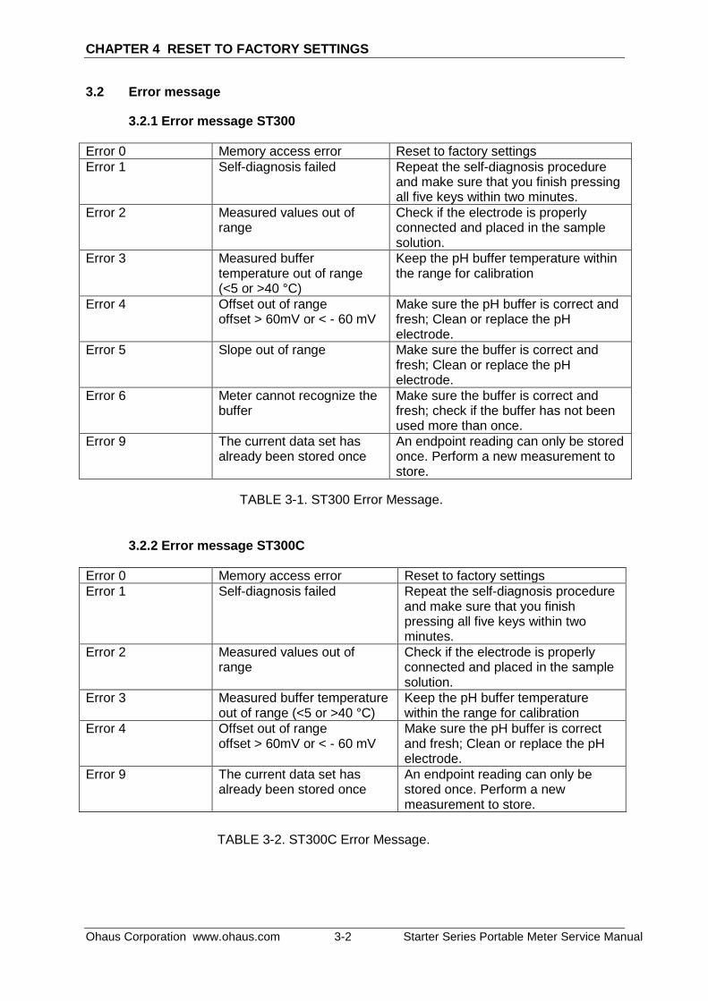
3.2.1 Error message ST300
Error 0 Memory access error Reset to factory settings
Error 1 Self-diagnosis failed Repeat the self-diagnosis procedure and make sure that you finish pressing all five keys within two minutes.
Error 2 Measured values out of range
Check if the electrode is properly connected and placed in the sample solution.
Error 3 Measured buffer temperature out of range (<5 or >40 °C)
Keep the pH buffer temperature within the range for calibration
Error 4 Offset out of range offset > 60mV or < - 60 mV
Make sure the pH buffer is correct and fresh; Clean or replace the pH electrode.
Error 5 Slope out of range Make sure the buffer is correct and fresh; Clean or replace the pH electrode.
Error 6 Meter cannot recognize the buffer
Make sure the buffer is correct and fresh; check if the buffer has not been used more than once.
Error 9 The current data set has already been stored once
An endpoint reading can only be stored once. Perform a new measurement to store.
3.2.2 Error message ST300C
Error 0 Memory access error Reset to factory settings
Error 1 Self-diagnosis failed Repeat the self-diagnosis procedure and make sure that you finish pressing all five keys within two minutes.
Error 2 Measured values out of range
Check if the electrode is properly connected and placed in the sample solution.
Error 3 Measured buffer temperature out of range (<5 or >40 °C)
Keep the pH buffer temperature within the range for calibration
Error 4 Offset out of range offset > 60mV or < - 60 mV
Make sure the pH buffer is correct and fresh; Clean or replace the pH electrode.
Error 9 The current data set has already been stored once
An endpoint reading can only be stored once. Perform a new measurement to store.
TABLE 3-1. ST300 Error Message.
TABLE 3-2. ST300C Error Message.

CHAPTER 3 RESET TO FACTORY SETTINGS
Starter Series Portable Meter Service Manual 3-3 Ohaus Corporation www.ohaus.com
3.2.3 Error message ST300D
Error 0 Memory access error Reset to factory settings
Error 1 Self-diagnosis failed Repeat the self-diagnosis procedure and make sure that you finish pressing all five keys within two minutes.
Error 2 Measured values out of range
Make sure that the electrode setting cap has been removed and the electrode is properly connected and placed in the sample solution.
Error 3 Measured buffer temperature out of range (<0°C or >50 °C)
Keep the standard buffer temperature within the range for calibration or measurement.
Error 4 Cal 2 out of range Make sure the buffer is correct and fresh; Clean or replace the DO electrode.
Error 5 Cal 1 out of range Make sure the buffer is correct and fresh; Clean or replace the DO electrode.
Error 9 The current data set has already been stored once
A measurement can only be stored once. Perform a new measurement to store a new data set.
3.2.4 Error message ST400D
Low battery If low battery, the battery icon will blink to show need new battery. Then turn off after 10 seconds.
Communication fail When do calibration or new cap parameter input, meter will detect if the probe is connected properly. If not, meter displays " Fail, please confirm the STDO21 probe is connected”
Measured temperature out of range (< -5°C or >55 °C)
Meter will display "Temperature Out of Range!"
Please keep the sample temperature within the range for measurement.
Calibration out of range Meter displays "Calibration Fail".
|K-1| >0.4 or a |B| >0.1
You may need to do a proper calibration again, if calibration data is still not good, you may need to replace a new probe cap or probe.
TABLE 3-3. ST300D Error Message.

CHAPTER 4 RESET TO FACTORY SETTINGS
Ohaus Corporation www.ohaus.com 3-4 Starter Series Portable Meter Service Manual
Recall memory fail Meter displays "No Data"
When recall memory while no data memorized yet.
The current data set has already been stored once
Meter displays" Already saved!"
A measurement can only be stored once. Perform a new measurement to store a new data set.
TABLE 3-4. ST400 Error Message.

CHAPTER 4 PARTS LISTS & DIAGRAMS
Starter Series Portable Series Service Manual 4-1 Ohaus Corporation www.ohaus.com
This section of the manual contains exploded views of the Starter ST300, ST300C, ST300D and ST400D portable meter. The exploded view drawings are designed to identify the parts which can be serviced on the portable meter in the field.
NOTE: Attention: In all cases where a part is replaced, the meter must be thoroughly checked after the replacement is made. The meter MUST meet the parameters of all applicable specifications in this manual.
Step to confirm the meter operates within specification:
1. Obtain a known good working condition electrode and buffer solution in hand.
2. Link the electrode to the portable meter, perform a calibration. After completed the calibration do a measurement and compare with the meter specification.
If further technical information is needed, please contact your local Ohaus distributor, or: www.ohaus.com Ohaus Corporation 7 Campus Drive Suite 310 Parsippany, NJ 07054 USA Tel: +1 973-377-9000 Fax: +1 973-593-0359 In the United States call toll free, 800-526-0659 between 8:00 a.m. and 6:00 p.m. EST.

CHAPTER 4 PARTS LISTS & DIAGRAMS
Ohaus Corporation www.ohaus.com 4-2 Starter Series Portable Series Service Manual
4.1 ST300, ST300C and ST300D Portable Meter: PARTS
Figure 4-1. ST300, ST300C and ST300D: Parts.
TABLE 4-1 ST300, ST300C and ST300D Meter: PARTS
Drawing Item Description
1 SP Housing STARTER 300x 2 SP Overlay ST300x EN 3 SP Overlay ST300x ZH 4 SP PCBA ST300x EN
5 SP PCBA ST300x ZH
6 SP Cover Battery
Note: For parts numbers, see your local Ohaus distributor, or visit www.ohaus.com.

CHAPTER 4 PARTS LISTS & DIAGRAMS
Starter Series Portable Series Service Manual 4-3 Ohaus Corporation www.ohaus.com
4.2 ST400D Portable pH Meter: PARTS
Figure 4-2. ST400D: Parts
TABLE 4-2 ST400D Meter: PARTS
Drawing Item Description
1 SP Housing STARTER 400D 2 SP Overlay ST400D EN 3 SP Overlay ST400D ZH 4 SP PCBA ST400D 5 SP Cover Battery
Note: For parts numbers, see your local Ohaus distributor, or visit www.ohaus.com.


*30257132*
P/N 30257132A SERVICE MANUAL: Starter Portable Series
Top Related