


Languages
Pages
Legal


High-‐resolu,on, texture-‐mapped 3D graphics and high-‐defini,on streaming video are escala,ng bandwidth needs between CPUs and graphics processors. Technologies like high-‐speed networking (Gigabit Ethernet, InfiniBand, etc.) and wireless communica,ons (Bluetooth) are allowing more devices to exchange growing amounts of data at rapidly increasing speeds. SoLware technologies are evolving, resul,ng in breakthrough methods of u,lizing mul,ple system processors. As processor speeds rise, so will the need for very fast, high-‐volume inter-‐processor data traffic.
The need for Hypertransport


Improve system performance − Provide increased I/O bandwidth − Reduce data boTlenecks by moving slower devices out of cri,cal informa,on paths − Reduce the number of buses within the system − Ensure low latency responses − Reduce power consump,on Simplify system design − Use a common protocol for “in-‐chassis” connec,ons to I/O and processors − Use as few pins as possible to allow smaller packages and to reduce cost Increase I/O flexibility − Provide a modular bridge architecture − Allow for differing upstream and downstream bandwidth requirements Maintain compa;bility with legacy systems − Complement standard external buses − Have liTle or no impact on exis,ng opera,ng systems and drivers Ensure extensibility to new system network architecture (SNA) buses Provide highly scalable mul;processing systems
Hypertransport design goals

Features of HyperTransport
• Its point to point approach. • Only two device per connection . • Low voltage differential signaling on high speed paths. • Precise control over PCB trace length & routing. • Source synchronous clock using Dual Data Rate (DDR) technology. • Sophisticated protocol eliminate retries ,disconnect & wait states. • Provides support for isochronous traffic . • CRC error detection and elimination. • Support for buses for legacy support . • PCI compatibility for minimal impact on OS and driver software. • Provides Networking support .

Greatly Increased Bandwidth Commands, addresses, and data traveling on a HyperTransport link are doublepumped, where transfers take place on both the rising and falling edges of the clock signal. For example, if the link clock is 800 MHz, the data rate is 1600 MHz. An implementa,on of HyperTransport links with 16 CAD bits in each direc,on with a 1.6-‐GHz data rate provides bandwidth of 3.2 Gigabytes per second in each direc,on, for an aggregate peak bandwidth of 6.4 Gbytes/s, or 48 ,mes the peak bandwidth of a 33-‐MHz PCI bus. A low-‐cost, low-‐power HyperTransport link using two CAD bits in each direc,on and clocked at 400 MHz provides 200 Mbytes/s of bandwidth in each direc,on, or nearly four ,mes the peak bandwidth of PCI 32/33. Such a link can be implemented with just 24 pins, including power and ground pins, as shown in Table 3.


HyperTransport Topologies HyperTransport technology is designed to support up to 32 devices per channel and can mix
and match components with different link widths and speeds.
Daisy chain Environment This capability makes it possible to create HyperTransport technology devices that are
building blocks capable of spanning a range of platforms and Market segment. e.g A low-‐cost entry in a mainstream PC product line might be designed with an AMD Duron™
processor. With very little redesign work, as shown in Figure this PC design could be upgraded to a high-‐end workstation by substituting high-‐end AMD Athlon™ processors and bridges with HyperTransport technology to expand the platform’s I/O capabilities.


Switch Environment § In this type of configuration, a HyperTransport I/O switch handles multiple
HyperTransport I/O data streams and manages the interconnection between the attached HyperTransport devices.
e.g A four-‐port HyperTransport switch could aggregate data from multiple
downstream ports into a single high-‐speed uplink, or it could route port-‐to-‐port connections. A switched environment allows multiple high-‐speed data paths to be linked while simultaneously supporting slower speed buses.

Star topology
Whereas daisy chain configurations offer linear bus topologies much like a network “backbone,” and switch topologies expand these into parallel chains, a star topology approach that distributes HyperTransport technology links in a spoke fashion around a central host or switch offers a great deal of
flexibility.

Multiprocessor Implementation

Flexible I/O Architecture
Conceptually ,the architecture of the
HyperTransport I/O link can be mapped into five different layers ,whose structure is similar to the Open System interconnection (OSI) reference model.
Session Layer
Transport Layer
Protocol Layer
Data Link Layer
Physical layer
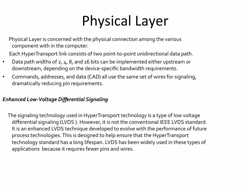
Physical Layer Physical Layer is concerned with the physical connection among the various
component with in the computer. Each HyperTransport link consists of two point-‐to-‐point unidirectional data path. • Data path widths of 2, 4, 8, and 16 bits can be implemented either upstream or
downstream, depending on the device-‐specific bandwidth requirements.
• Commands, addresses, and data (CAD) all use the same set of wires for signaling, dramatically reducing pin requirements.
Enhanced Low-‐Voltage Differential Signaling The signaling technology used in HyperTransport technology is a type of low voltage
differential signaling (LVDS ). However, it is not the conventional IEEE LVDS standard. It is an enhanced LVDS technique developed to evolve with the performance of future process technologies. This is designed to help ensure that the HyperTransport technology standard has a long lifespan. LVDS has been widely used in these types of applications because it requires fewer pins and wires.

A point-‐to-‐point parallel bus like HyperTransport has many advantages over shared bus structures. It needs far fewer sideband signals because its enhanced 1.2V LVDS signals are not mul,plexed, use less power, exhibit beTer noise immunity and require no passive filtering. The electrical characteris,cs of the link are simplified and enable much faster clock speeds and correspondingly greater bandwidth.
Hypertransport


Data link Layer
The data link layer concerned with
• initialization and configuration sequence, periodic
• cyclic redundancy check (CRC),
• disconnect/reconnect sequence,
• information packets for flow control and error management, and
• double word framing for other packets

Protocol Layer
• The protocol layer includes the commands, the virtual channels in which they run, and the ordering rules that govern their flow.
Transport Layer
• The transaction layer uses the elements provided by the protocol layer to
perform actions, such as read request and responses.
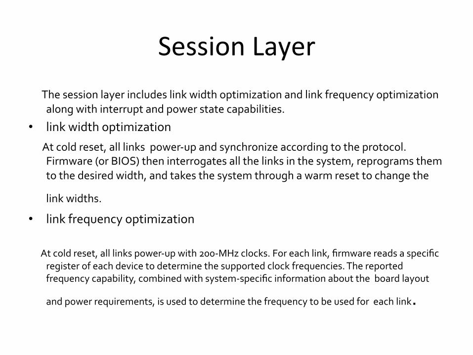
Session Layer The session layer includes link width optimization and link frequency optimization
along with interrupt and power state capabilities.
• link width optimization
At cold reset, all links power-‐up and synchronize according to the protocol. Firmware (or BIOS) then interrogates all the links in the system, reprograms them to the desired width, and takes the system through a warm reset to change the
link widths. • link frequency optimization
At cold reset, all links power-‐up with 200-‐MHz clocks. For each link, firmware reads a specific register of each device to determine the supported clock frequencies. The reported frequency capability, combined with system-‐specific information about the board layout
and power requirements, is used to determine the frequency to be used for each link.

Hypertransport Packet format


HyperTransport Control Packets Base control packets are generally 4 to 8 byte long (in case of 64-‐bit adressing they are12
byte long). It is divided into three types
Request Packet à Sized read write ,flush ,fence ,Broadcast message,Atomic read modify
Response PacketàRead ,Target Done Info PacketàNOP ,Sync/Error
Control Packet
Request Response Info

Applica;ons for HyperTransport • Front-‐Side Bus Replacement The primary use for HyperTransport is to replace the front-‐side bus, which is
currently different for every type of machine. computer implemented with HyperTransport is faster and more flexible. A single PCI↔HyperTransport adaptor chip will work with any HyperTransport enabled microprocessor and allow the use of PCI cards with these processors.
• Multiprocessor interconnect Another use for HyperTransport is as an interconnect for NUMA multiprocessor
computers. AMD uses HyperTransport with a proprietary cache coherency extension as part of their Direct Connect Architecture in their Opteron and Atholon 64FX (DCA)The HORUS interconnect from Newisys extends this concept to larger clusters .

• Router or Switch Bus Replacement • HyperTransport can also be used as a bus in routers and switches. Routers and
switches have multiple connections ports and data has to be forwarded between these ports as fast as possible
• HTX and Co-‐processor interconnect • The issue of bandwidth between CPUs and co-‐processors has usually been the
major stumbling block to their practical implementation. After years without an officially recognized one, a connector designed for such expansion using a HyperTransport interface was introduced and is known as HyperTransport expansion (HTX)

Conclusion • HyperTransport technology is a powerful board-‐level architecture that
delivers high bandwidth, low latency, scalability, PCI compatibility, and extensibility.
• When processor-‐native, HyperTransport provides an integrated front-‐side bus that eliminates custom/proprietary buses and the need for additional glue logic.
• As an integrated I/O bus, HyperTransport eliminates the need for multiple local buses, ultimately simplifying overall system design and implementation.
• As a link to legacy PCI and PCI-‐X subsystems, HyperTransport extends the life of those popular systems and as a lemerging, high-‐speed serial buses such as PCI Express, it becomes a board-‐level system architecture
Top Related