


Languages
Pages
Legal

7 December 2016 1
The design of soil nailed structures to AS4678___
Chris BridgesTechnical Principal - Geotechnics

Presentation Layout
2
• Introduction
• Soil Nailing in AS4678
• Design Process
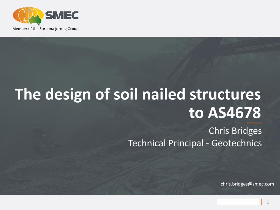
Soil Nail – Main Components
HDPE Sheath (for corrosion protection)
External centraliser
Internal centraliser
Outer grout tube
Inner grout tube
Soil nail head plate (galvanised for corrosion protection)
Domed soil nail nut (galvanised for corrosion protection)
32mm diameter deformed soil nail bar (galvanised for corrosion protection)
3

Construction

Reinforcing the soil

Figure 2.13 Forces Acting on a Potential Sliding Zone for a Nailed Slope
(Phear et al., 2005)
RN - resisting forces (nail)
RS - resisting forces (soil)
RD - disturbing forces
Active Zone
Passive
Zone
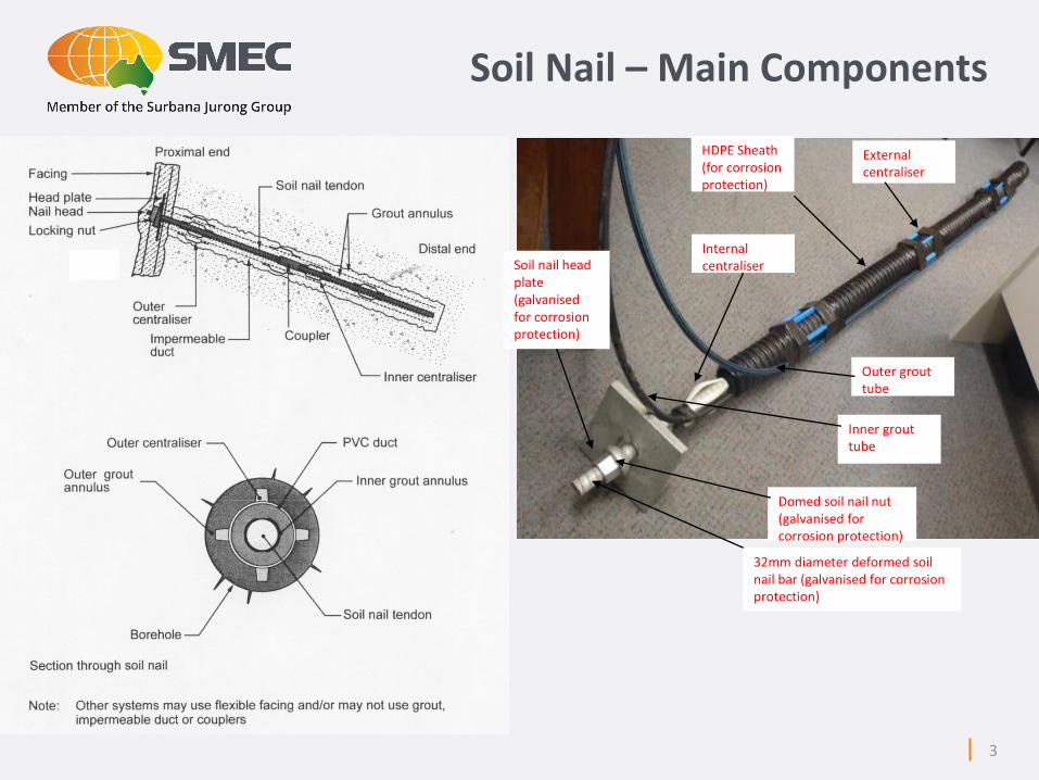
How soil nails work
Soil nailed wall
How soil nails work
7
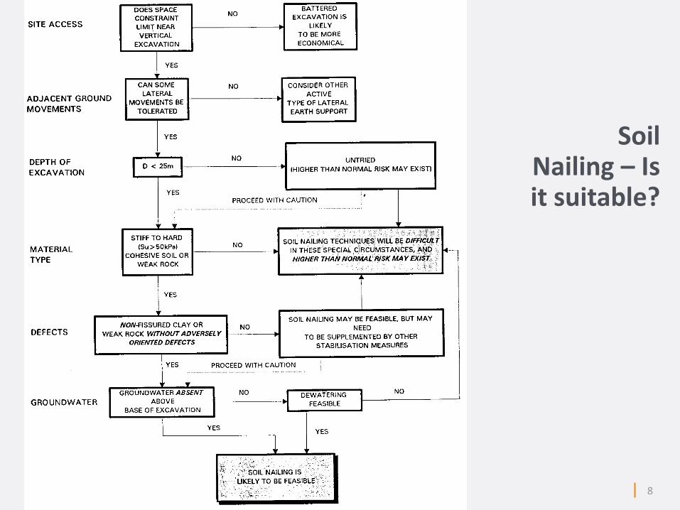
Soil Nailing – Is it suitable?
8
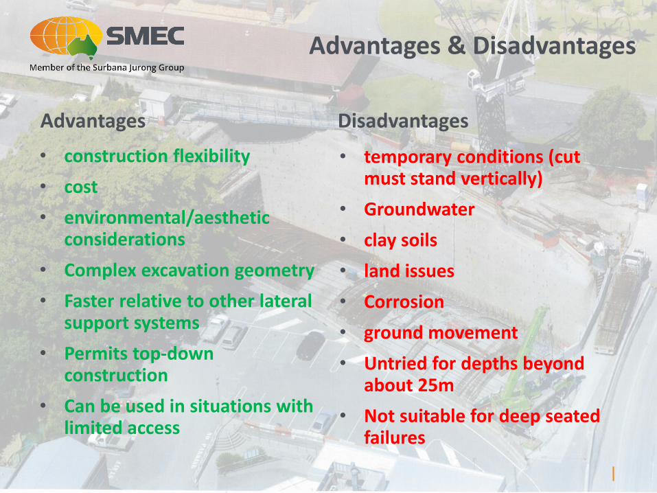
Advantages Disadvantages
• construction flexibility
• cost
• environmental/aesthetic considerations
• Complex excavation geometry
• Faster relative to other lateral support systems
• Permits top-down construction
• Can be used in situations with limited access
• temporary conditions (cut must stand vertically)
• Groundwater
• clay soils
• land issues
• Corrosion
• ground movement
• Untried for depths beyond about 25m
• Not suitable for deep seated failures
Advantages & Disadvantages
7 December 2016
AS4678 - 2002
10

11
• Design Considerations – Limit States
• Strength - Must consider all critical conditions during the excavation/nail installation process
• Serviceability – must include movements during excavation
• External Stability
• Internal Stability
• Design Loads – load combinations & factors
• Design Factors – factors on material properties & uncertainty
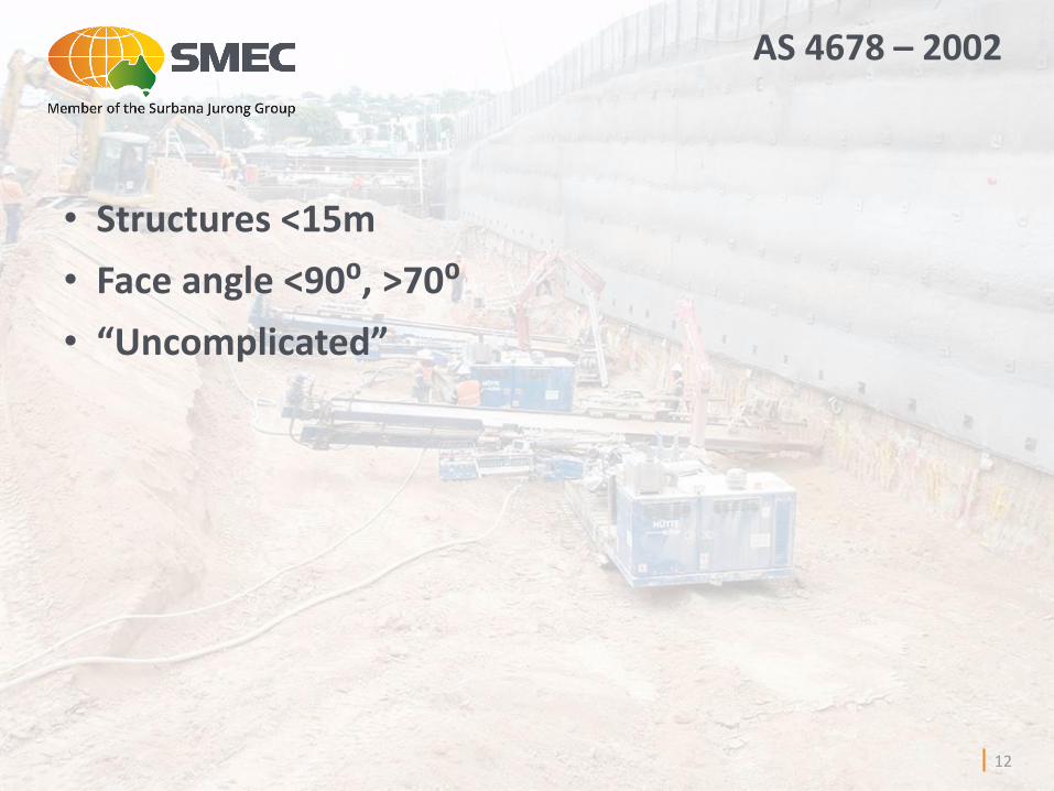
AS 4678 – 2002
12
• Structures <15m
• Face angle <90⁰, >70⁰
• “Uncomplicated”
AS 4678 – 2002

AS 4678 – 2002
• Informative Guidelines only
• Appendix C of AS4678
• Design principle is similar to Reinforced Soil Walls
• Appendix C refers back to Appendix B – Ground anchors
13
7 December 2016
Design Process
14

Design Process
15

Design Process
16
7 December 2016
Step 2 – Input parameters
17

Soil Properties – Uncertainty Factors
18
f* = design angle of internal friction of soil (deg.)(= tan-1(Fuf (tanf’));
c* = design value of cohesion of soil (kN/m2) (=c’ Fuc);
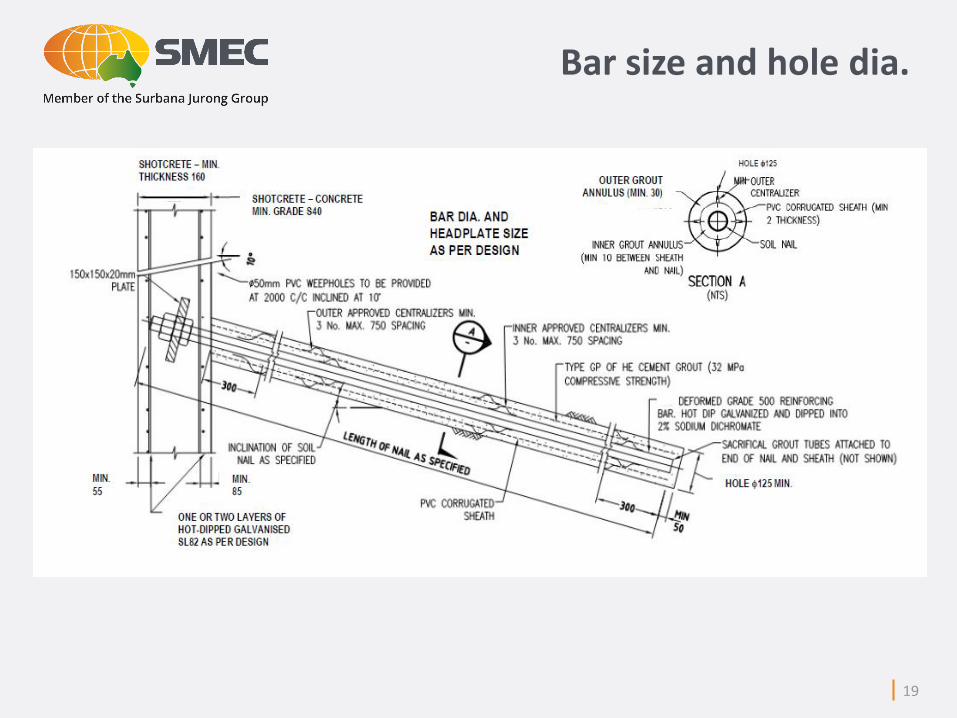
Bar size and hole dia.
19
7 December 2016
Step 3 - Concept
20

MODEL 1
No soil nails
Planar failure
Ref.: Zhang et al, 2001
MODEL 6
Short soil nails
L/H = 0.32
Block failure
MODEL 8
Long, widely spaced soil nails
L/H = 1
Planar failure
Nail spacing, length and inclination
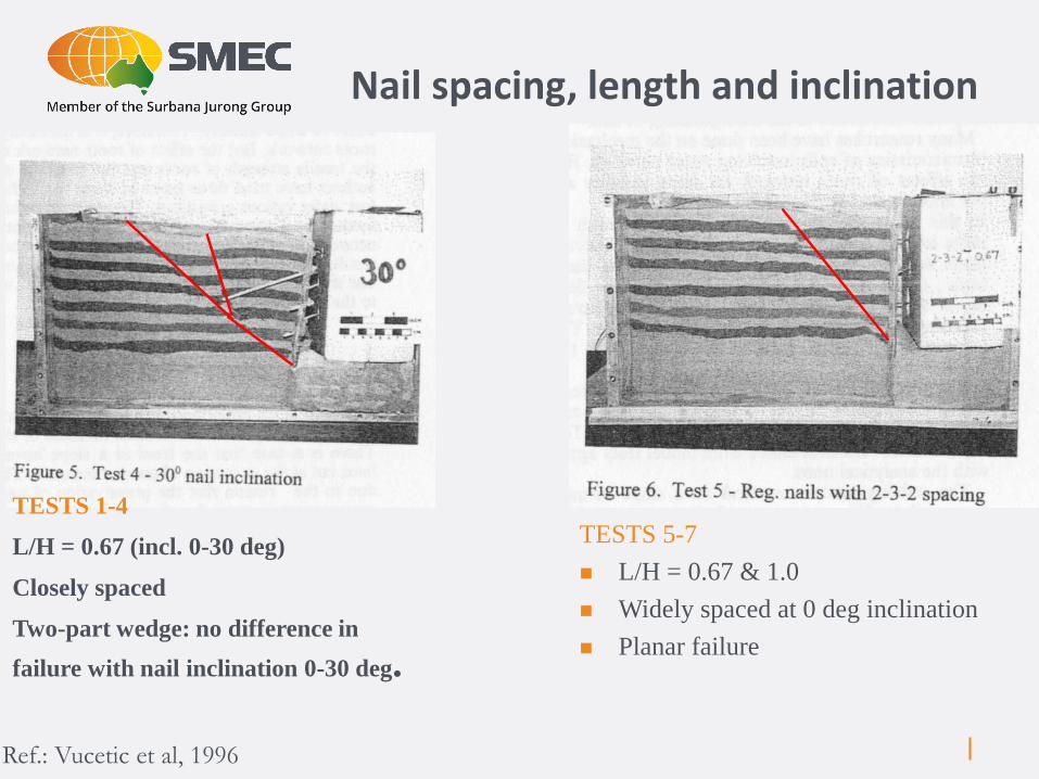
Ref.: Vucetic et al, 1996
TESTS 5-7
L/H = 0.67 & 1.0
Widely spaced at 0 deg inclination
Planar failure
TESTS 1-4
L/H = 0.67 (incl. 0-30 deg)
Closely spaced
Two-part wedge: no difference in
failure with nail inclination 0-30 deg.
Nail spacing, length and inclination

Nail spacing, length and inclination
Factor of safety for different soil nail inclinations (90° wall face angle)
Factor of safety for different L/H ratios (90° wall face angle)
23
0.000
0.010
0.020
0.030
0.040
0.050
0.060
0.070
0.80
1.20
1.60
2.00
2.40
-5 0 5 10 15 20 25 30
De
form
atio
n (
m)
F.O
.S
Nail Inclination (deg)
FOS Vertical Deformation
Horizontal Deformation
f'=36°, c’=6kPa
0.000
0.005
0.010
0.015
0.020
0.025
0.81.21.6
22.42.83.23.6
44.44.85.2
0.5 0.6 0.7 0.8 0.9 1.0 1.1 1.2 1.3
De
form
atio
n (
m)
F.O
.S
L/H Ratio
FOS Vertical Deformation
Horizontal Deformation
f'=36°, c’=6kPa
H
L
Inclination
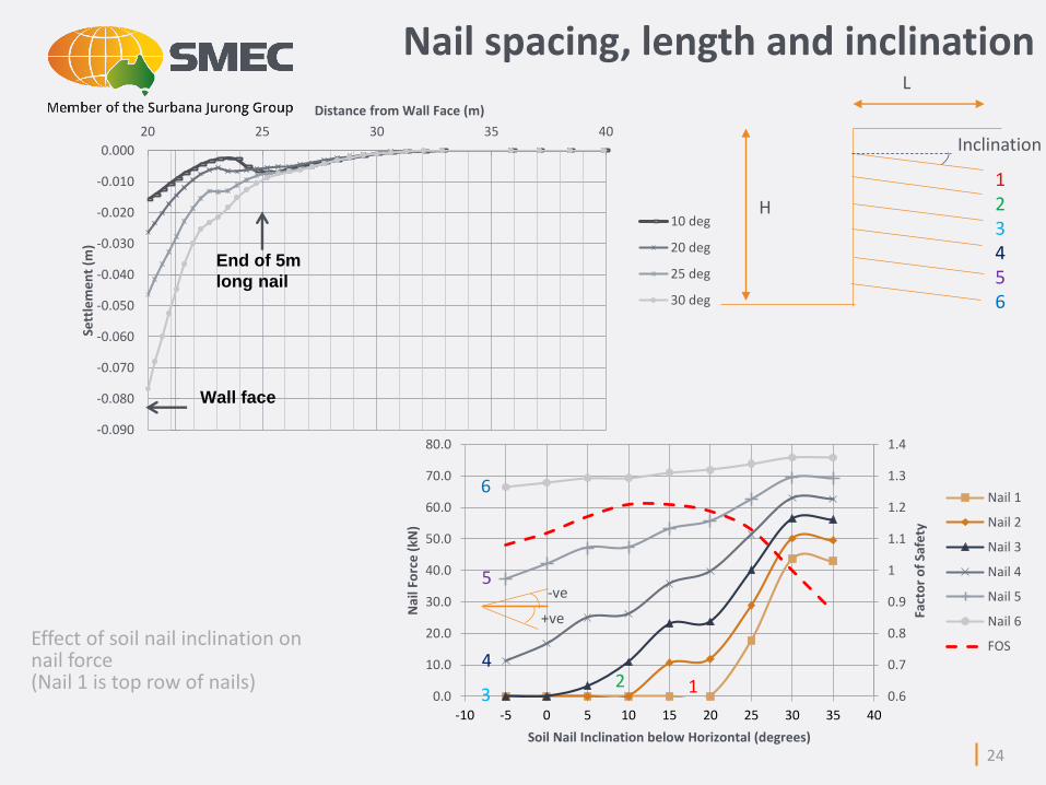
Effect of soil nail inclination on nail force (Nail 1 is top row of nails)
24
-0.090
-0.080
-0.070
-0.060
-0.050
-0.040
-0.030
-0.020
-0.010
0.000
20 25 30 35 40
Sett
lem
en
t (m
)
Distance from Wall Face (m)
10 deg
20 deg
25 deg
30 deg
Wall face
End of 5m
long nail
0.6
0.7
0.8
0.9
1
1.1
1.2
1.3
1.4
0.0
10.0
20.0
30.0
40.0
50.0
60.0
70.0
80.0
-10 -5 0 5 10 15 20 25 30 35 40
Fact
or
of
Safe
ty
Nai
l Fo
rce
(kN
)
Soil Nail Inclination below Horizontal (degrees)
Nail 1
Nail 2
Nail 3
Nail 4
Nail 5
Nail 6
FOS
+ve
Inclination
H
123456
-ve
L
6
5
3
42 1
Nail spacing, length and inclination
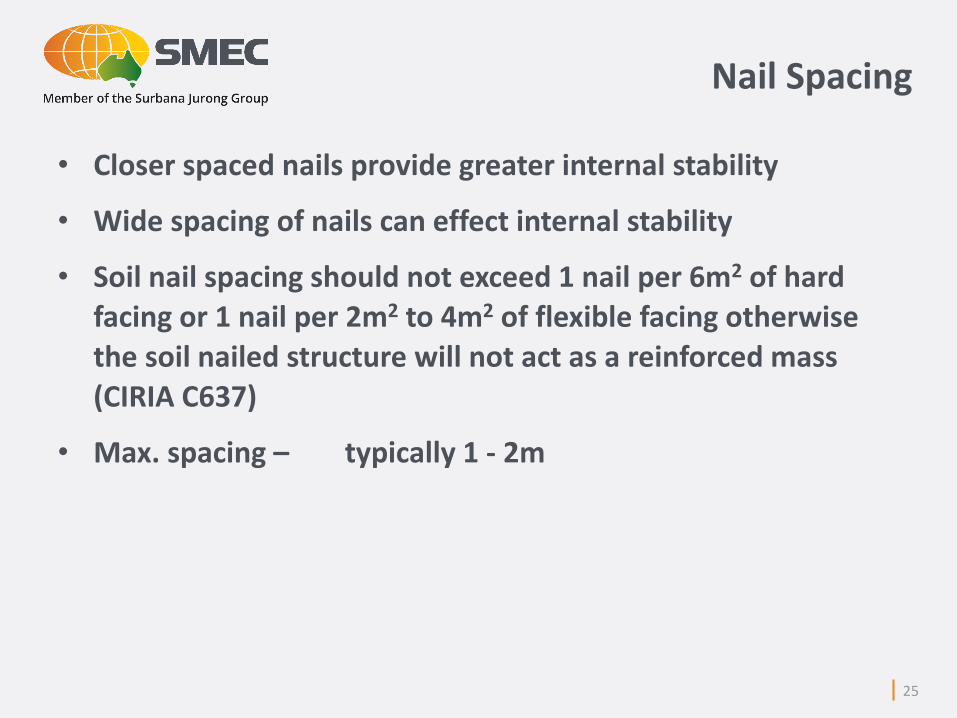
• Closer spaced nails provide greater internal stability
• Wide spacing of nails can effect internal stability
• Soil nail spacing should not exceed 1 nail per 6m2 of hard facing or 1 nail per 2m2 to 4m2 of flexible facing otherwise the soil nailed structure will not act as a reinforced mass (CIRIA C637)
• Max. spacing – typically 1 - 2m
Nail Spacing
25
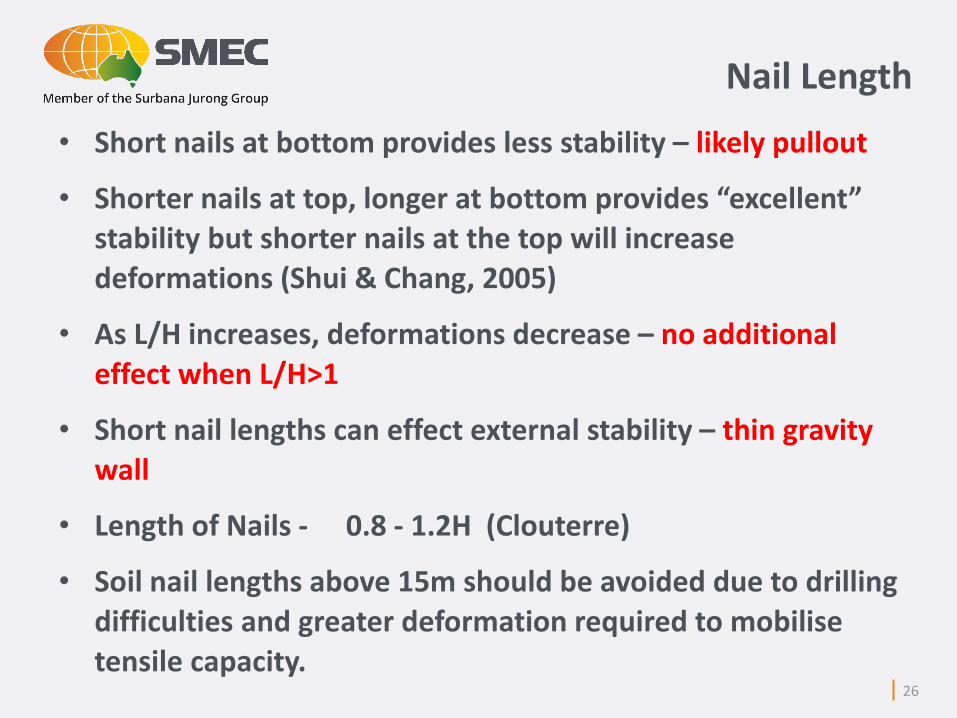
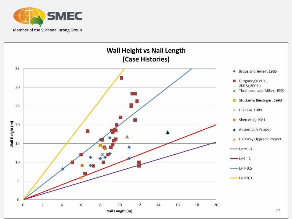
• Short nails at bottom provides less stability – likely pullout
• Shorter nails at top, longer at bottom provides “excellent” stability but shorter nails at the top will increase deformations (Shui & Chang, 2005)
• As L/H increases, deformations decrease – no additional effect when L/H>1
• Short nail lengths can effect external stability – thin gravity wall
• Length of Nails - 0.8 - 1.2H (Clouterre)
• Soil nail lengths above 15m should be avoided due to drilling difficulties and greater deformation required to mobilise tensile capacity.
26
Nail Length
27
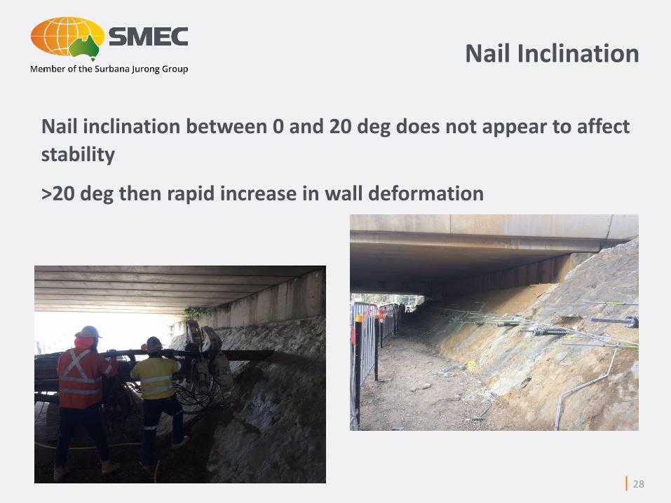
Nail inclination between 0 and 20 deg does not appear to affect stability
>20 deg then rapid increase in wall deformation
28
Nail Inclination

Preliminary Sizing
The following relationships were derived by Bruce & Jewell (1987):
Length Ratio = Length of soil nail / Excavation height (L/H)
Bond Ratio = (Hole Dia. x L) / Nail Spacing
Strength Ratio = (Nail Dia.)2 / Nail Spacing
Nail Spacing = horizontal spacing x vertical spacing (m2)
Performance Ratio = Outward Movement = d
Excavation height H
Marl – mix of calcium carbonate & clay
Morraine – glacial debris (silt thru to boulders)
29

7 December 2016
Step 4 - Analyses
30
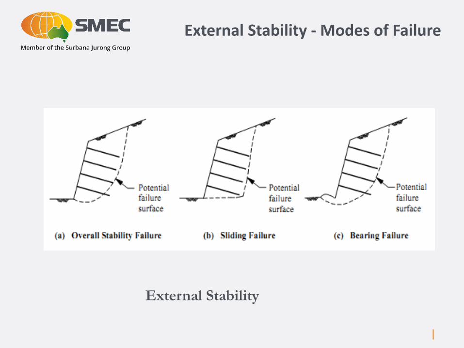
External Stability - Modes of Failure
External Stability
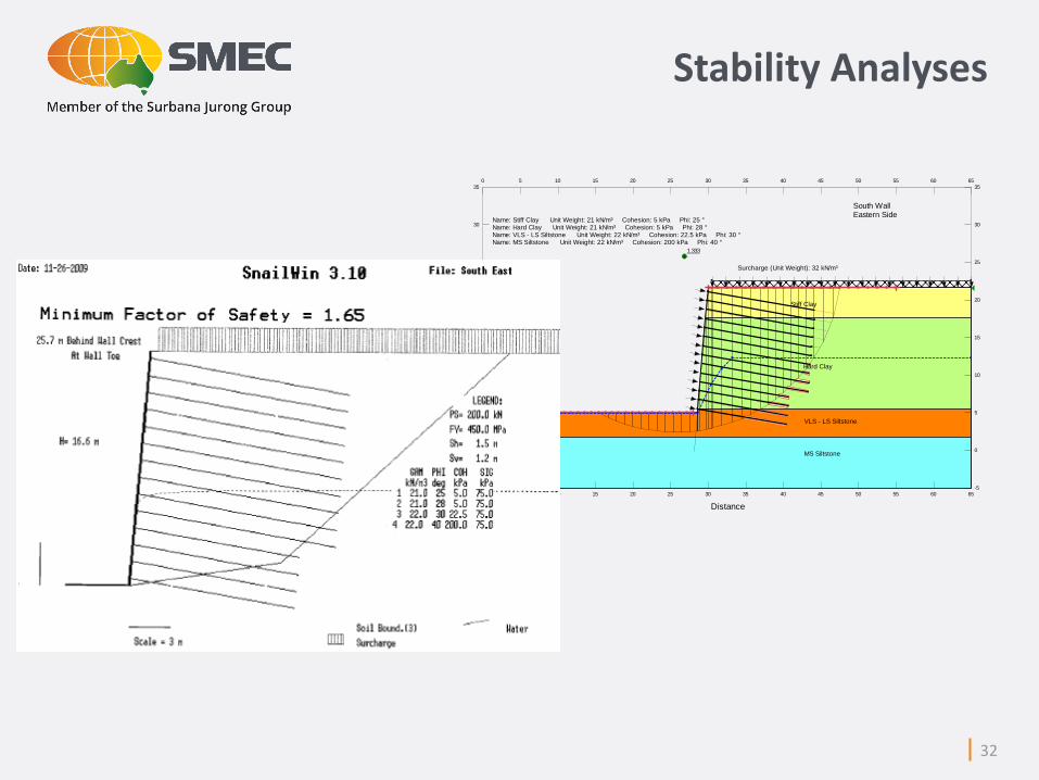
Stability Analyses
1.333
Surcharge (Unit Weight): 32 kN/m³
Name: Stiff Clay Unit Weight: 21 kN/m³ Cohesion: 5 kPa Phi: 25 ° Name: Hard Clay Unit Weight: 21 kN/m³ Cohesion: 5 kPa Phi: 28 ° Name: VLS - LS Siltstone Unit Weight: 22 kN/m³ Cohesion: 22.5 kPa Phi: 30 ° Name: MS Siltstone Unit Weight: 22 kN/m³ Cohesion: 200 kPa Phi: 40 °
Stiff Clay
Hard Clay
VLS - LS Siltstone
MS Siltstone
South WallEastern Side
Distance
0 5 10 15 20 25 30 35 40 45 50 55 60 65-5
0
5
10
15
20
25
30
350 5 10 15 20 25 30 35 40 45 50 55 60 65
Ele
va
tion
(m
RL
)
-5
0
5
10
15
20
25
30
35
32

Nail Tension Forces
33

Modes of Failure
Internal Stability

Soil Nailing – Internal Stability
• Soil nail pull-out (grout-ground bond)
• Nail failure (i.e. tensile failure of nail)
• Pull-out of connection to facing material
35
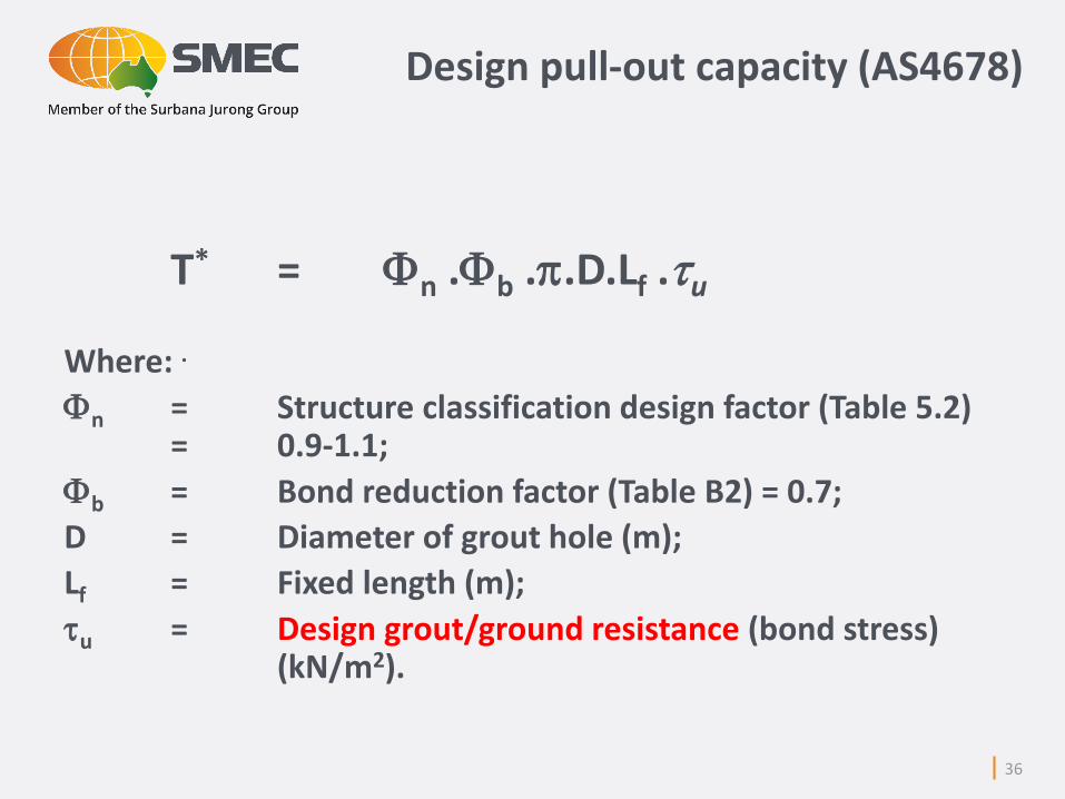
Design pull-out capacity (AS4678)
T* = Fn .Fb ..D.Lf .u
Where: .
Fn = Structure classification design factor (Table 5.2) = 0.9-1.1;
Fb = Bond reduction factor (Table B2) = 0.7;
D = Diameter of grout hole (m);
Lf = Fixed length (m);
u = Design grout/ground resistance (bond stress) (kN/m2).
36
• Effective stress design methods
• Pull out tests
• Empirical values
37
Bond Stress

Design bond stress (effective stress design method)
u = (c* + σ‘v tanf*) (kN/m2)
where:
σ‘v = effective vertical stress at the mid-depth of nail behind the failure surface;
f* = design angle of internal friction of soil (deg.);
c* = design value of cohesion of soil (kN/m2).
38
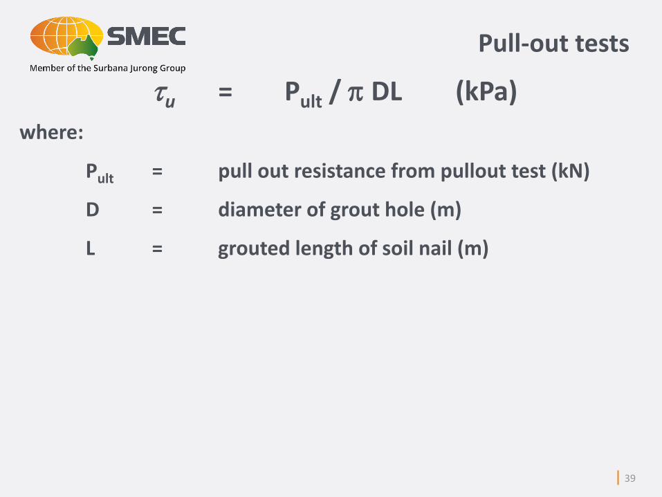
Pull-out tests
u = Pult / DL (kPa)
where:
Pult = pull out resistance from pullout test (kN)
D = diameter of grout hole (m)
L = grouted length of soil nail (m)
39
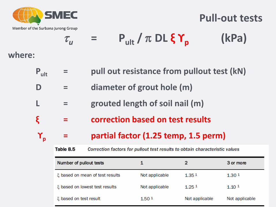
Pull-out tests
u = Pult / DL ξ ϒp (kPa)
where:
Pult = pull out resistance from pullout test (kN)
D = diameter of grout hole (m)
L = grouted length of soil nail (m)
ξ = correction based on test results
ϒp = partial factor (1.25 temp, 1.5 perm)
40
Material Ultimate Bond Stress (kPa)
Material Ultimate Bond Stress (kPa)
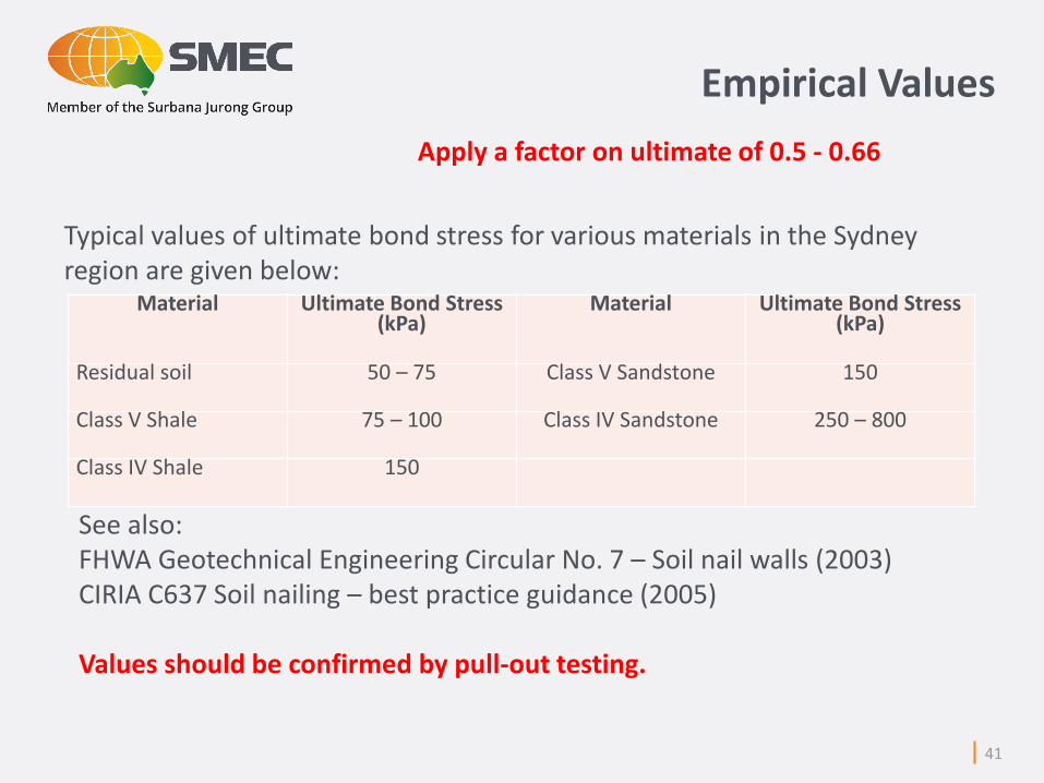
Residual soil 50 – 75 Class V Sandstone 150
Class V Shale 75 – 100 Class IV Sandstone 250 – 800
Class IV Shale 150
Typical values of ultimate bond stress for various materials in the Sydney region are given below:
See also:FHWA Geotechnical Engineering Circular No. 7 – Soil nail walls (2003)CIRIA C637 Soil nailing – best practice guidance (2005)
Values should be confirmed by pull-out testing.
41
Empirical Values
Apply a factor on ultimate of 0.5 - 0.66
Design pull-out capacity
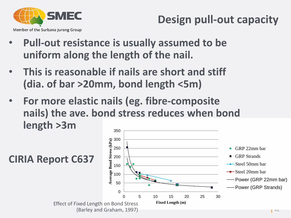
• Pull-out resistance is usually assumed to be uniform along the length of the nail.
• This is reasonable if nails are short and stiff (dia. of bar >20mm, bond length <5m)
• For more elastic nails (eg. fibre-composite nails) the ave. bond stress reduces when bond length >3m
CIRIA Report C637
42
0
50
100
150
200
250
300
350
0 5 10 15 20 25 30
Av
era
ge
Bo
nd
Str
ess
(kP
a)
Fixed Length (m)
GRP 22mm bar
GRP Strands
Steel 50mm bar
Steel 20mm bar
Power (GRP 22mm bar)
Power (GRP Strands)
Effect of Fixed Length on Bond Stress (Barley and Graham, 1997)
Nail tensile capacity
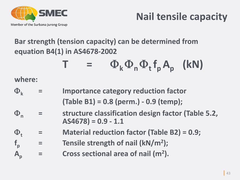
Bar strength (tension capacity) can be determined from
equation B4(1) in AS4678-2002
T = Fk Fn Ft fp Ap (kN)where:
Fk = Importance category reduction factor
(Table B1) = 0.8 (perm.) - 0.9 (temp);
Fn = structure classification design factor (Table 5.2, AS4678) = 0.9 - 1.1
Ft = Material reduction factor (Table B2) = 0.9;
fp = Tensile strength of nail (kN/m2);
Ap = Cross sectional area of nail (m2).
43
Facing
44
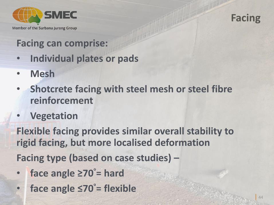
Facing can comprise:
• Individual plates or pads
• Mesh
• Shotcrete facing with steel mesh or steel fibrereinforcement
• Vegetation
Flexible facing provides similar overall stability to rigid facing, but more localised deformation
Facing type (based on case studies) –
• face angle ≥70°= hard
• face angle ≤70°= flexible
45

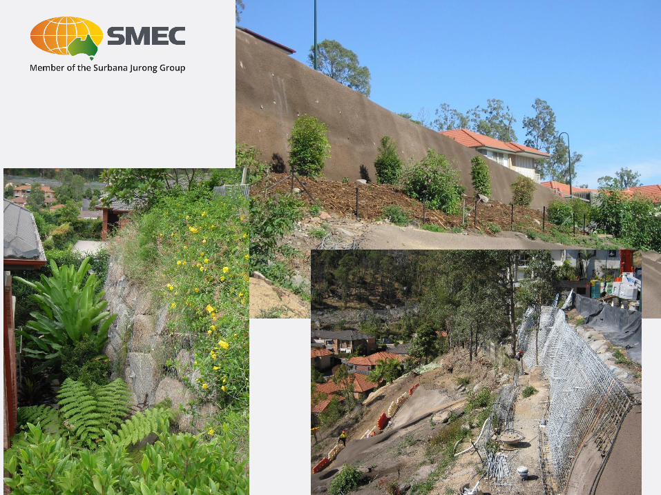
Vegetated Slope Works
July 2001 August 2001
September 2002 April 2003
June 2001
47
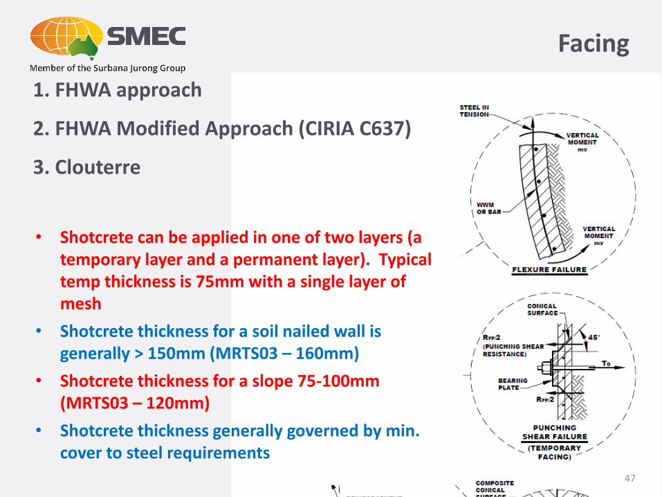
Facing
1. FHWA approach
2. FHWA Modified Approach (CIRIA C637)
3. Clouterre
• Shotcrete can be applied in one of two layers (a temporary layer and a permanent layer). Typical temp thickness is 75mm with a single layer of mesh
• Shotcrete thickness for a soil nailed wall is generally > 150mm (MRTS03 – 160mm)
• Shotcrete thickness for a slope 75-100mm (MRTS03 – 120mm)
• Shotcrete thickness generally governed by min. cover to steel requirements
Soil Nailing - Serviceability
Serviceability limit state of soil nailed structure is similar to RSW.
Remember – movement is required to generate resistance. Therefore beware of existing structures on top of proposed cut.
Where special concrete facings are used, any excessive deformation of the facing may constitute a serviceability limit state.
48
49
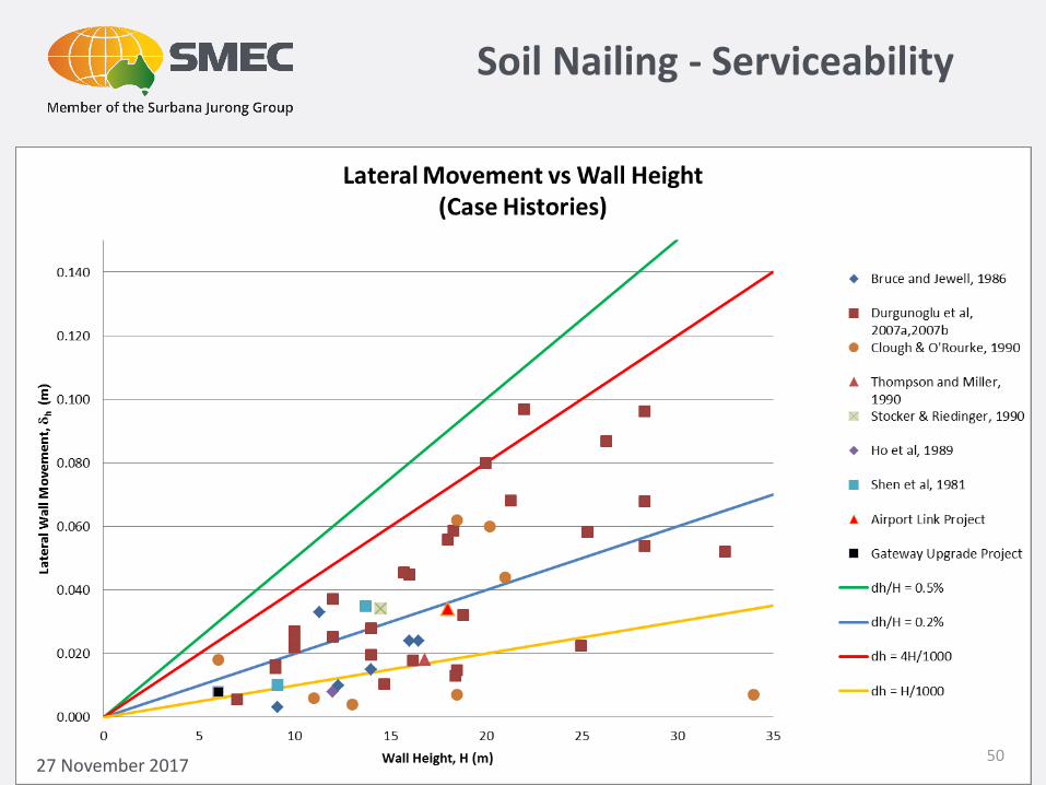
Soil Nailing - Serviceability
27 November 201750

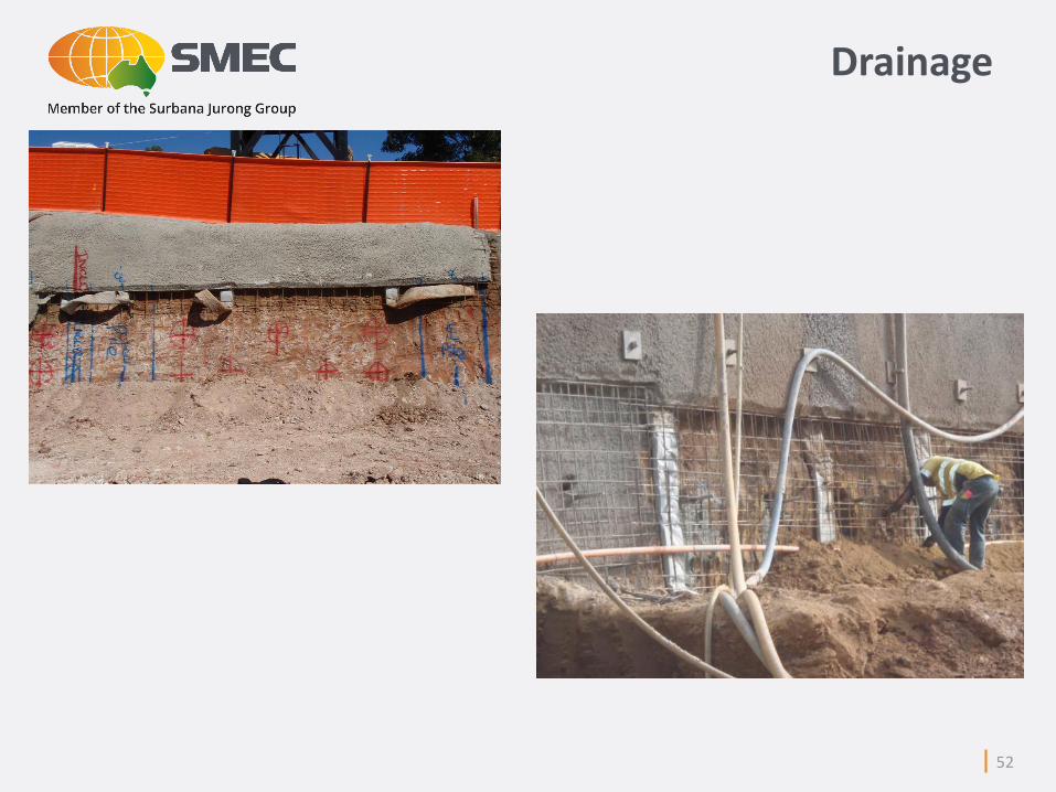
Drainage
51
52
Drainage
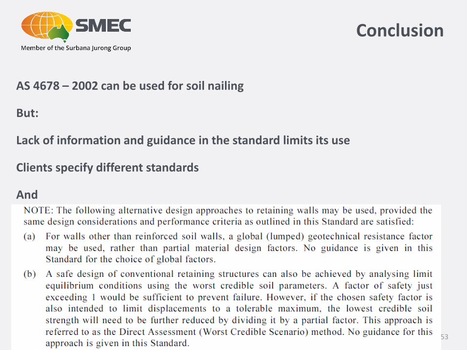
Conclusion
AS 4678 – 2002 can be used for soil nailing
But:
Lack of information and guidance in the standard limits its use
Clients specify different standards
And
53

7 December 2016
Thank you
54
7 December 2016
Construction Issues
55
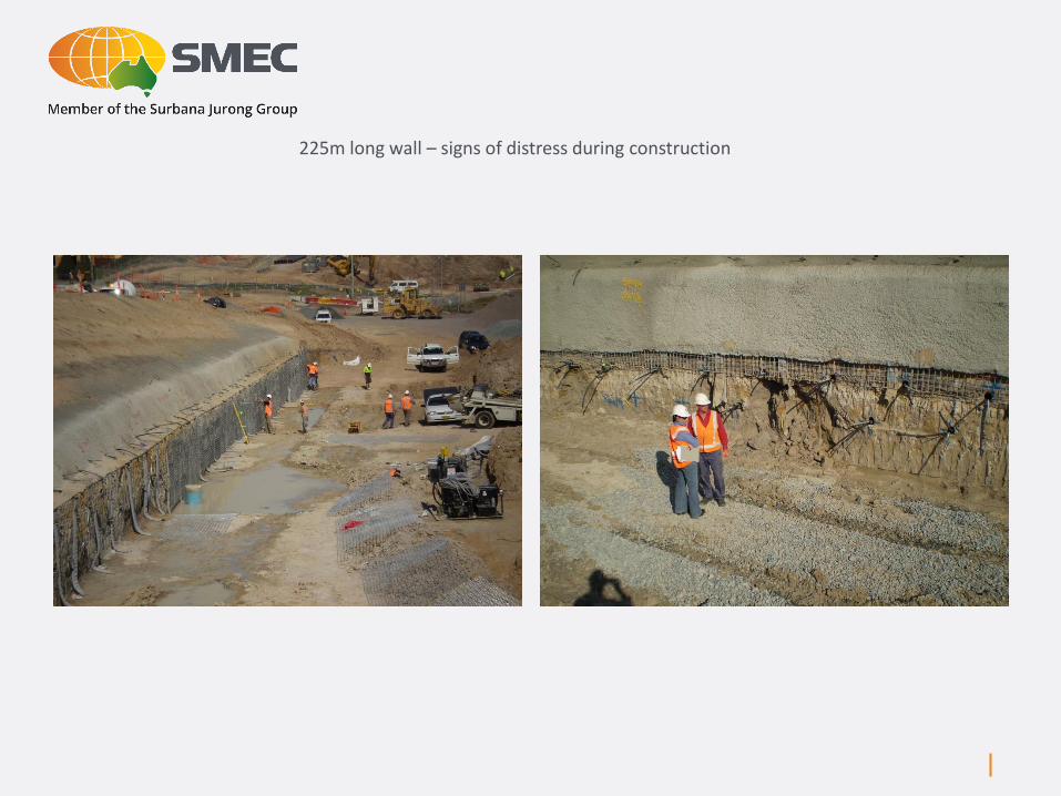
225m long wall – signs of distress during construction

1
2 3
4
5
6
7 8
9
10
11
12
13 14
15
1.51
Mudstone
Original Design
Sandstone
Claystone
Name: General Backfill
Model: Mohr-Coulomb
Unit Weight: 19 kN/m³
Cohesion: 5 kPa
Phi: 30 °
Name: Claystone
Model: Mohr-Coulomb
Unit Weight: 21 kN/m³
Cohesion: 10 kPa
Phi: 40 °
Name: Mudstone
Model: Mohr-Coulomb
Unit Weight: 21 kN/m³
Cohesion: 10 kPa
Phi: 42 °
Name: Sandstone
Model: Mohr-Coulomb
Unit Weight: 20 kN/m³
Cohesion: 2 kPa
Phi: 42 °
Sandstone
Directory: K:\Q1215 - LMI\Coffey\Design\Walls\RW08\
Pressure (Unit Weight): 20 kN/m³
General Backfill
Offset (m)
0 5 10 15 20 25 30 35
He
igh
t (m
)
0
5
10
15
20
25
57
1
2 3
4
5
6
7 8
9
10
11
12
13 14
15
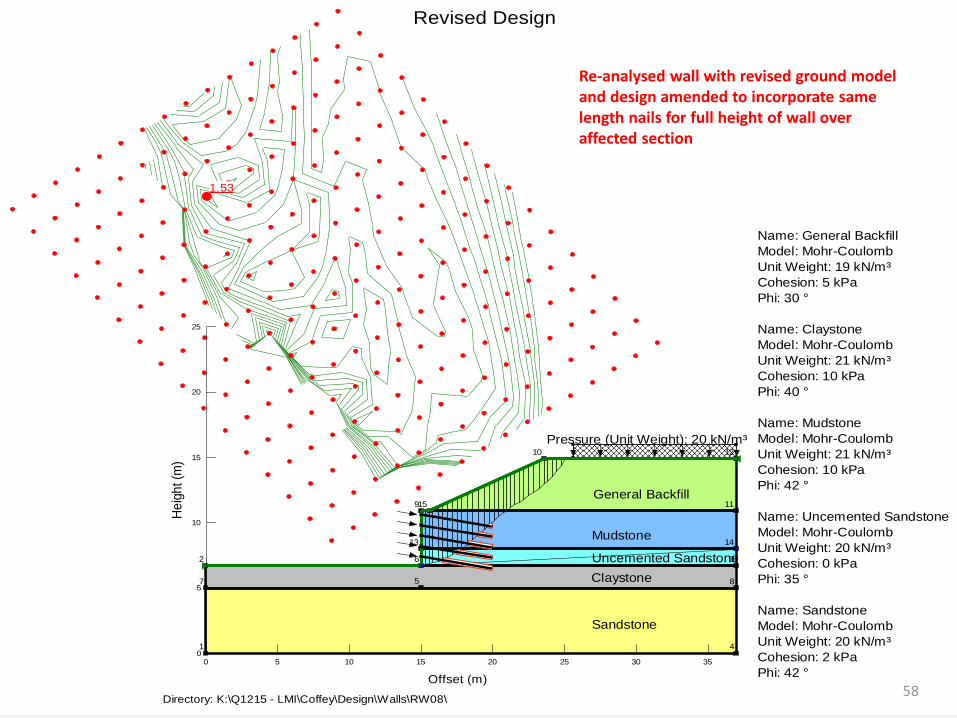
1.53
Mudstone
Revised Design
Sandstone
Claystone
Name: General Backfill
Model: Mohr-Coulomb
Unit Weight: 19 kN/m³
Cohesion: 5 kPa
Phi: 30 °
Name: Claystone
Model: Mohr-Coulomb
Unit Weight: 21 kN/m³
Cohesion: 10 kPa
Phi: 40 °
Name: Mudstone
Model: Mohr-Coulomb
Unit Weight: 21 kN/m³
Cohesion: 10 kPa
Phi: 42 °
Name: Uncemented Sandstone
Model: Mohr-Coulomb
Unit Weight: 20 kN/m³
Cohesion: 0 kPa
Phi: 35 °
Name: Sandstone
Model: Mohr-Coulomb
Unit Weight: 20 kN/m³
Cohesion: 2 kPa
Phi: 42 °
Uncemented Sandstone
Directory: K:\Q1215 - LMI\Coffey\Design\Walls\RW08\
Pressure (Unit Weight): 20 kN/m³
General Backfill
Offset (m)
0 5 10 15 20 25 30 35
He
igh
t (m
)
0
5
10
15
20
25
Re-analysed wall with revised ground model and design amended to incorporate same length nails for full height of wall over affected section
58
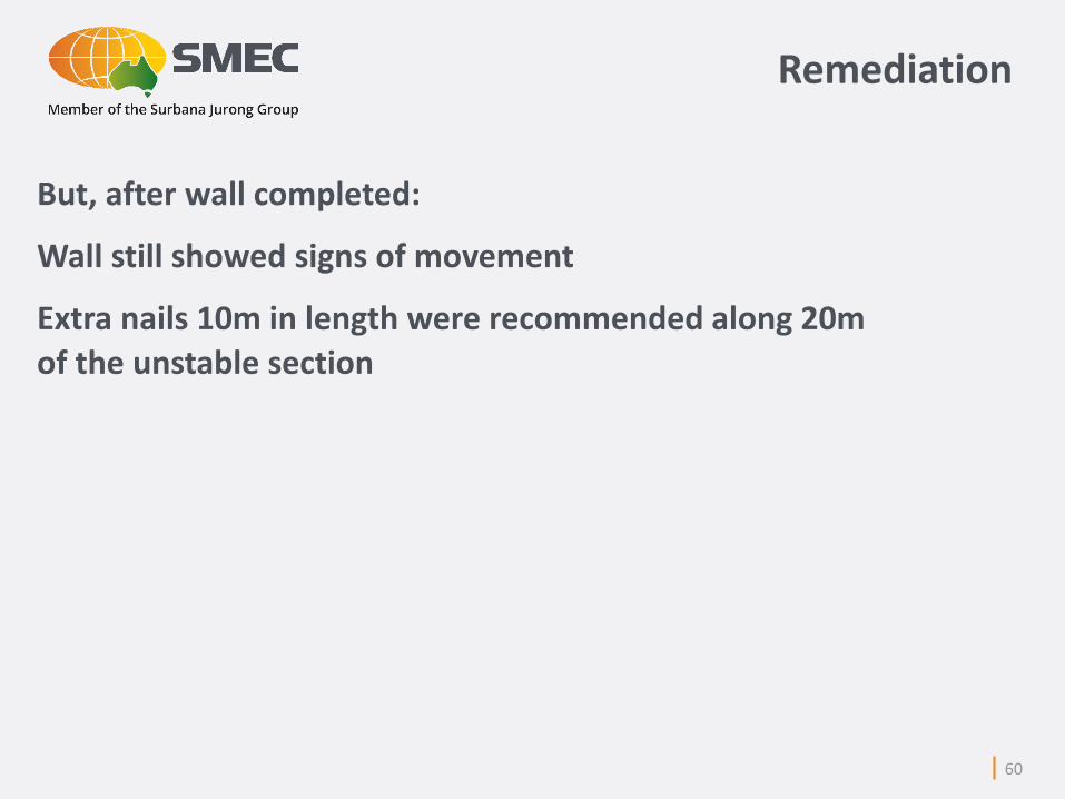
Remediation
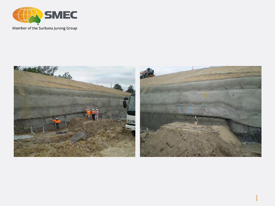
But, after wall completed:
Wall still showed signs of movement
Extra nails 10m in length were recommended along 20m
of the unstable section
60

1
2 3
4
5
6
7 8
9
10
11
12
13 14
15
1.59
Mudstone
Remediation Nail Design
Sandstone
Claystone
Name: General Backfill
Model: Mohr-Coulomb
Unit Weight: 19 kN/m³
Cohesion: 5 kPa
Phi: 30 °
Name: Claystone
Model: Mohr-Coulomb
Unit Weight: 21 kN/m³
Cohesion: 10 kPa
Phi: 40 °
Name: Mudstone
Model: Mohr-Coulomb
Unit Weight: 21 kN/m³
Cohesion: 10 kPa
Phi: 42 °
Name: Uncemented Sandstone
Model: Mohr-Coulomb
Unit Weight: 20 kN/m³
Cohesion: 0 kPa
Phi: 35 °
Name: Sandstone
Model: Mohr-Coulomb
Unit Weight: 20 kN/m³
Cohesion: 2 kPa
Phi: 42 °
Uncemented Sandstone
Directory: K:\Q1215 - LMI\Coffey\Design\Walls\RW08\
Pressure (Unit Weight): 20 kN/m³
General Backfill
Offset (m)
0 5 10 15 20 25 30 35
He
igh
t (m
)
0
5
10
15
20
25
61

Spacers of inadequate strength
Damage to installed soil nail bars by
excavator
Lack of experience of contractors staff
62

Soil Nail Failures
Ref.: Tan. & Chow, 2004
Soil nail facing failure
Grout cover cracked and
peeled off from nail

Void within
cement grout
~250mm
Probed depth = 320 mm
into cement grout
Probed depth = 1590 mm
into cement grout
Cross-section
Soil Nail Failures
64

Nail with
no grout
Plastic sheet
Short
column of
cement
grout
65
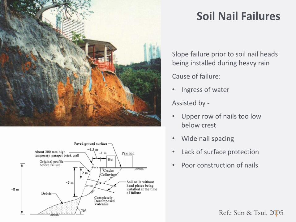
Soil Nail Failures
Ref.: Sun & Tsui, 2005
Slope failure prior to soil nail heads being installed during heavy rain
Cause of failure:
• Ingress of water
Assisted by -
• Upper row of nails too low below crest
• Wide nail spacing
• Lack of surface protection
• Poor construction of nails
Soil Nail Failures
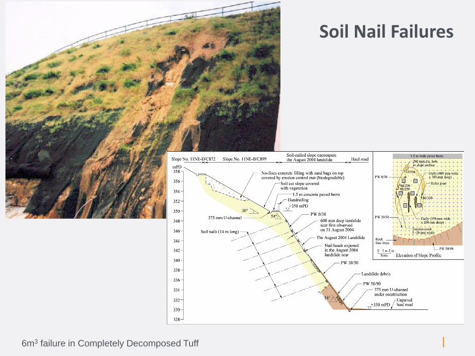
6m3 failure in Completely Decomposed Tuff

Soil Nail Walls are not such a great idea in water charged sands and silts
(They also can’t be expected to have a 2 weeks stand up time)
Airport Link – Construction Issues
68

Soil Nails and Reinforced Soil
69

Excavations – Soil Nails
70
Top Related