


Languages
Pages
Legal

Chapter 3: Number Systems and Codes
Textbook: Petruzella, Frank D., Programmable Logic Controllers. McGraw Hill Companies Inc., 5th edition

Decimal System
The radix or base of a number system determines
the total number of different symbols or digits
used by the system.
The decimal system has a base of 10.
In the decimal system, 10 unique numbers or
digits ( 0 through 9) are used: the total number
of symbols is the same as the base, and the symbol
with the largest value is 1 less than the base.

Decimal System
The decimal system can be summarized as follows:
Ten digits: 0, 1, 2, 3, 4, 5, 6, 7, 8, 9
Base: 10
Weights: 1, 10, 100, 1000, …(powers of base 10)

Weighted value in the decimal system
Decimal System

Binary System
The binary system has a base of 2.
The only allowable digits are 0 and 1
Digital Signal Waveform: with digital circuits it is easy
to distinguish between two voltage levels - +5 V and O V,
which can be related to the binary digits 1 and 0.
Time
Volts +5
0
High (H) (1)
Low (L) (0)

Binary System
The binary system can be summarized as follows:
Two digits: 0, 1
Base: 2
Weights: 1, 2, 4, 8, 16, 32, …(powers of base 2)

Decimal
Binary
0
0000
1
0001
2
0010
3 0011
4 0100
5 0101
6 0110
7 0111
8 1000
Binary System
Since the binary system uses only
two digits, each position of a binary
number can go through only two
changes, and then a 1 is carried to
the immediate left position.
To express the number in the
binary system requires many
more digits than in the decimal
system.
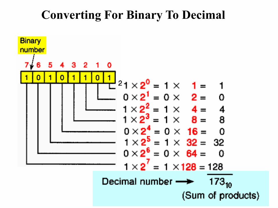
Converting For Binary To Decimal
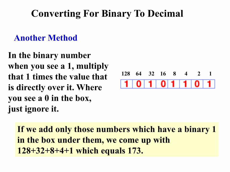
Another Method
In the binary number
when you see a 1, multiply
that 1 times the value that
is directly over it. Where
you see a 0 in the box,
just ignore it.
128 64 32 16 8 4 2 1
If we add only those numbers which have a binary 1
in the box under them, we come up with
128+32+8+4+1 which equals 173.
Converting For Binary To Decimal
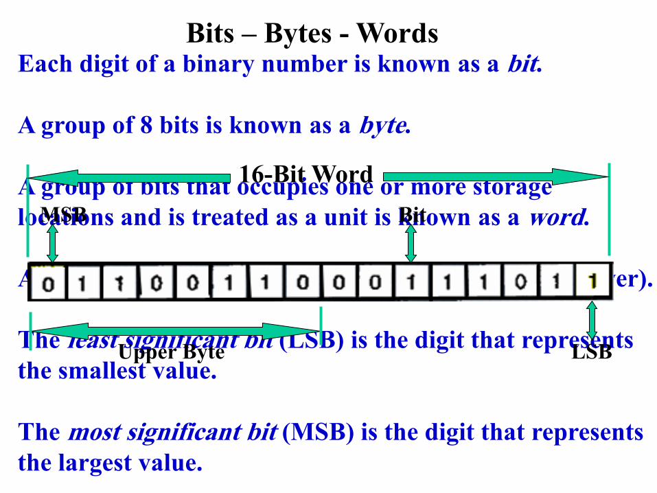
Bits – Bytes - Words Each digit of a binary number is known as a bit.
A group of 8 bits is known as a byte.
A group of bits that occupies one or more storage
locations and is treated as a unit is known as a word.
A 16-bit word is made up of two bytes (Upper and Lower).
The least significant bit (LSB) is the digit that represents
the smallest value.
The most significant bit (MSB) is the digit that represents
the largest value.
16-Bit Word
Bit
Upper Byte
MSB
LSB

PLC Processor Memory Size
The size of the programmable controller relates to the
amount of user program that can be stored.
The 1 K word memory
size shown can store
1,024 words, or 16,380
(1,024 x 16) bits of
information using
16-bit words or 32,768
(1,024 x 32) using
32 bit words.
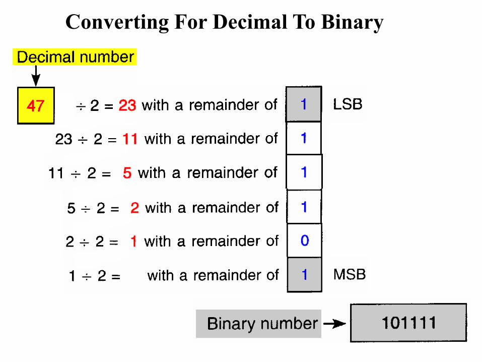
Converting For Decimal To Binary
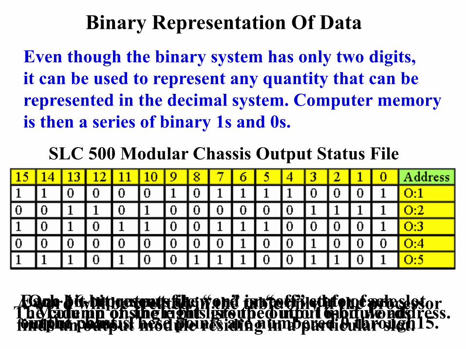
Binary Representation Of Data
Even though the binary system has only two digits,
it can be used to represent any quantity that can be
represented in the decimal system. Computer memory
is then a series of binary 1s and 0s.
SLC 500 Modular Chassis Output Status File
Made up of single bits grouped into 16-bit words One 16-bit output file word is reserved for each slot
in the chassis.
Each bit represents the “on” or “off” state of one
output point. These points are numbered 0 through15. The column on the right lists the output module address. A word will be created in the table only if the processor
finds an output module residing in a particular slot.
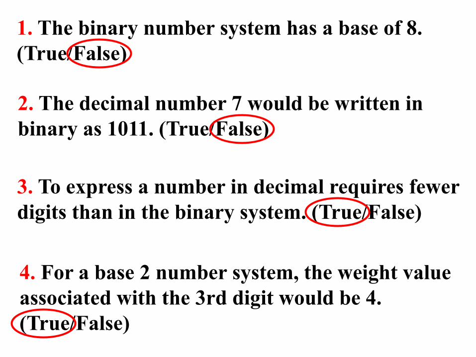
1. The binary number system has a base of 8.
(True/False)
2. The decimal number 7 would be written in
binary as 1011. (True/False)
3. To express a number in decimal requires fewer
digits than in the binary system. (True/False)
4. For a base 2 number system, the weight value
associated with the 3rd digit would be 4.
(True/False)

5. What is the decimal value of binary 110000 ?
a. 48 c. 13
b. 26 d. 7
6. The decimal number 15 would be written in
binary as:
a. 1111 c. 4C
b. 1000 d. 00011001
7. Data can be stored in one 16-bit word as two
separate groups of 8-bit data. (True/False)

8. A group of 8 bits is known as a byte.
(True/False)
9. The MSB is the digit that represents the
smallest value. (True/False)
10. Since the binary system has only two digits,
it is limited as far as representing very large
quantities. (True/False)

Negative Numbers
In the binary system it is not possible to use positive
and negative symbols to represent the polarity of a
number.
One method is of representing a binary number as
either a positive or negative value is to use an extra digit,
or sign bit, at the MSB of the number. In the sign bit
position, a “0” indicates that the number is positive,
and a “1” indicates a negative number.
Sign
Bit Magnitude Bits
Decimal
Value
Sign
Bit
Magnitude Bits
Decimal
Value
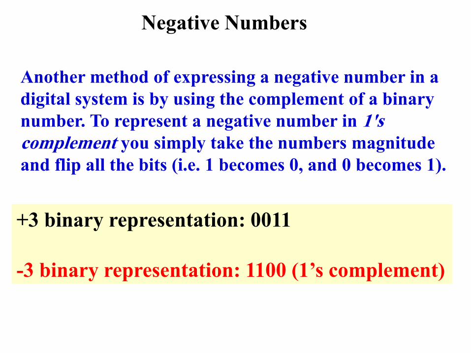
Negative Numbers
Another method of expressing a negative number in a
digital system is by using the complement of a binary
number. To represent a negative number in 1's
complement you simply take the numbers magnitude
and flip all the bits (i.e. 1 becomes 0, and 0 becomes 1).
+3 binary representation: 0011
-3 binary representation: 1100 (1’s complement)
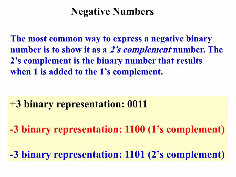
Negative Numbers
The most common way to express a negative binary
number is to show it as a 2’s complement number. The
2’s complement is the binary number that results
when 1 is added to the 1’s complement.
+3 binary representation: 0011
-3 binary representation: 1100 (1’s complement)
-3 binary representation: 1101 (2’s complement)
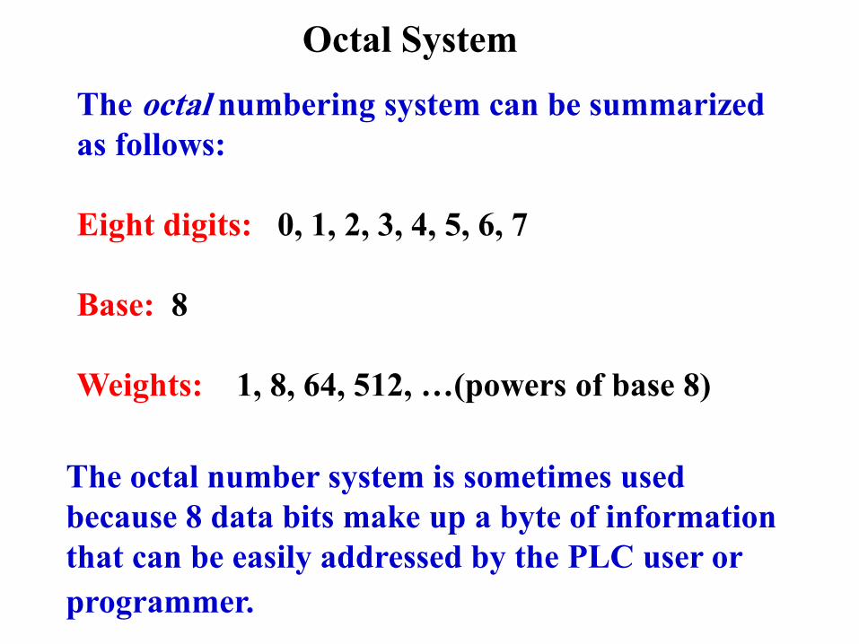
Octal System
The octal numbering system can be summarized
as follows:
Eight digits: 0, 1, 2, 3, 4, 5, 6, 7
Base: 8
Weights: 1, 8, 64, 512, …(powers of base 8)
The octal number system is sometimes used
because 8 data bits make up a byte of information
that can be easily addressed by the PLC user or
programmer.
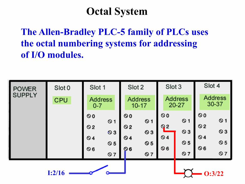
Octal System
The Allen-Bradley PLC-5 family of PLCs uses
the octal numbering systems for addressing
of I/O modules.
I:2/16 O:3/22
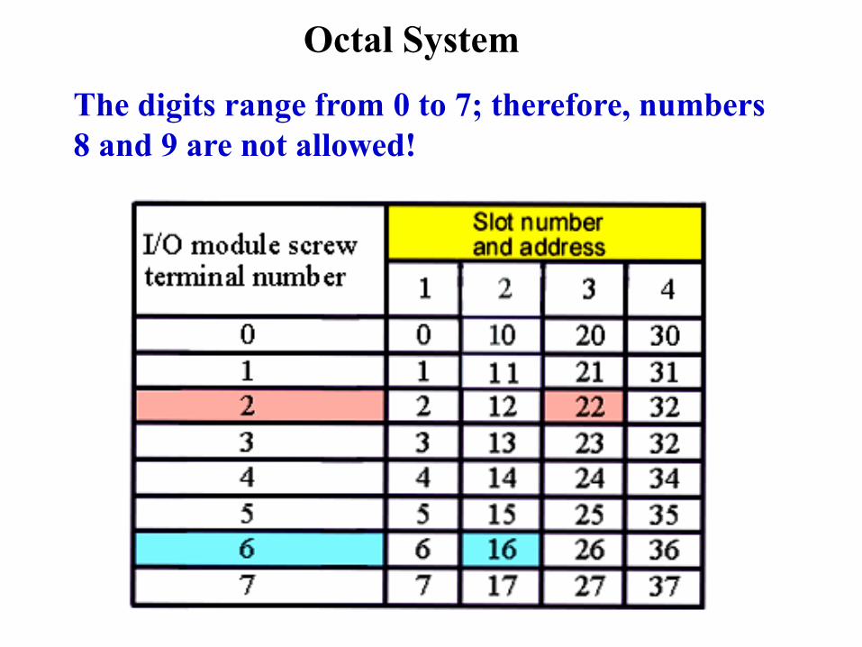
Octal System
The digits range from 0 to 7; therefore, numbers
8 and 9 are not allowed!
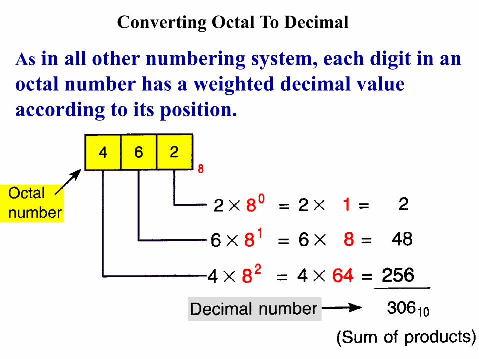
Converting Octal To Decimal
As in all other numbering system, each digit in an
octal number has a weighted decimal value
according to its position.
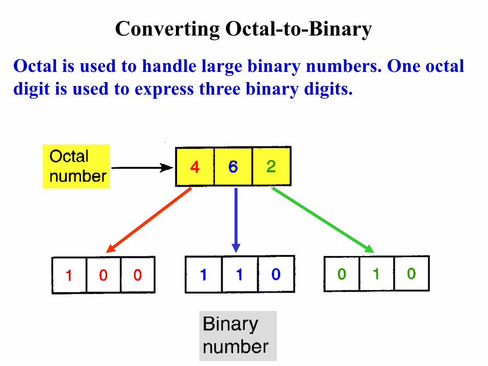
Converting Octal-to-Binary
Octal is used to handle large binary numbers. One octal
digit is used to express three binary digits.
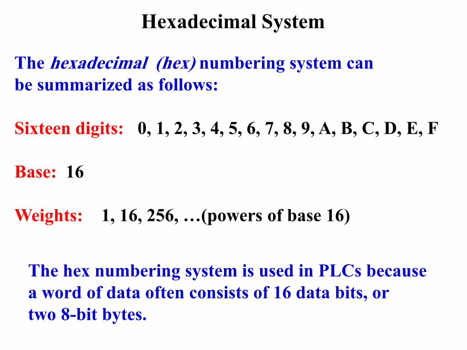
Hexadecimal System
The hexadecimal (hex) numbering system can
be summarized as follows:
Sixteen digits: 0, 1, 2, 3, 4, 5, 6, 7, 8, 9, A, B, C, D, E, F
Base: 16
Weights: 1, 16, 256, …(powers of base 16)
The hex numbering system is used in PLCs because
a word of data often consists of 16 data bits, or
two 8-bit bytes.
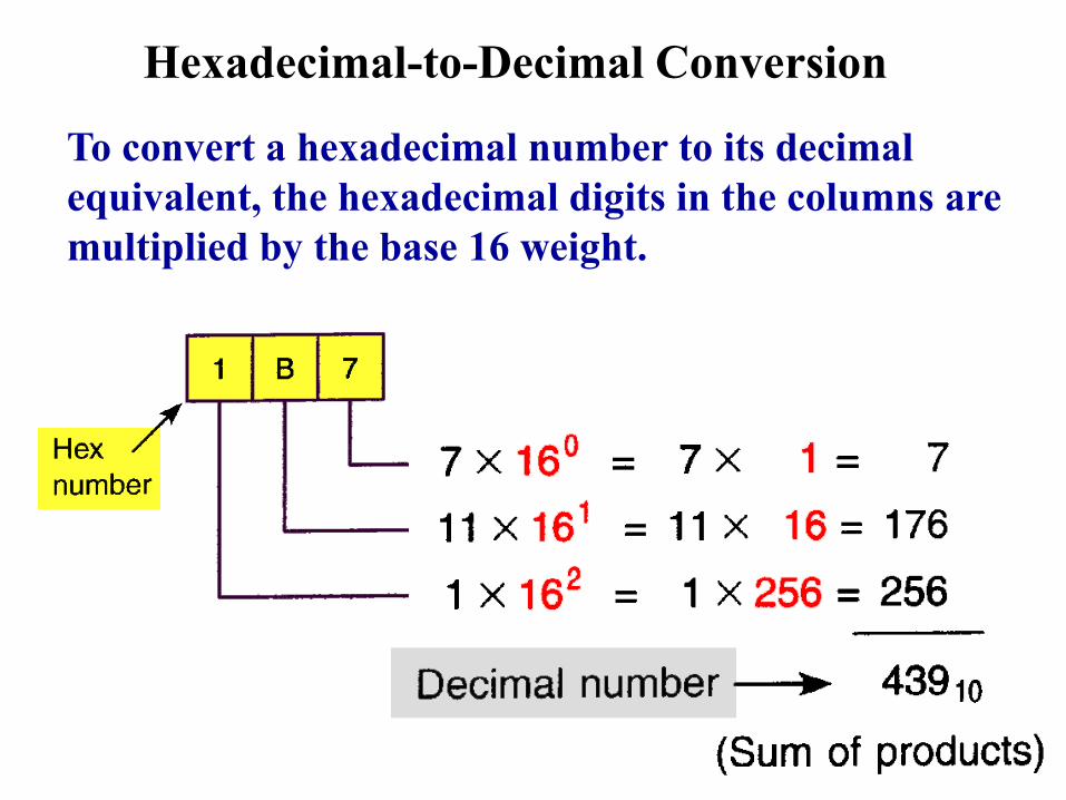
Hexadecimal-to-Decimal Conversion
To convert a hexadecimal number to its decimal
equivalent, the hexadecimal digits in the columns are
multiplied by the base 16 weight.

Hexadecimal-to-Binary Conversion
Using the hex numbering system allows the status
of a large number of binary bits to be represented
in a small space such as a PLC programming display.

BCD (Binary-Coded Decimal) System
The BCD (Binary-Coded Decimal) numbering system
provides a convenient way of handling large numbers
that need to be inputted to or outputted from a PLC.
There is no easy way to go from binary to decimal
and back. The BCD system provides a means of
converting a code readily handled by humans (decimal)
to a code readily handled by equipment (binary).

Examples Of Numeric
Values In:
Decimal,
Binary,
BCD,
and Hexadecimal,
Representation
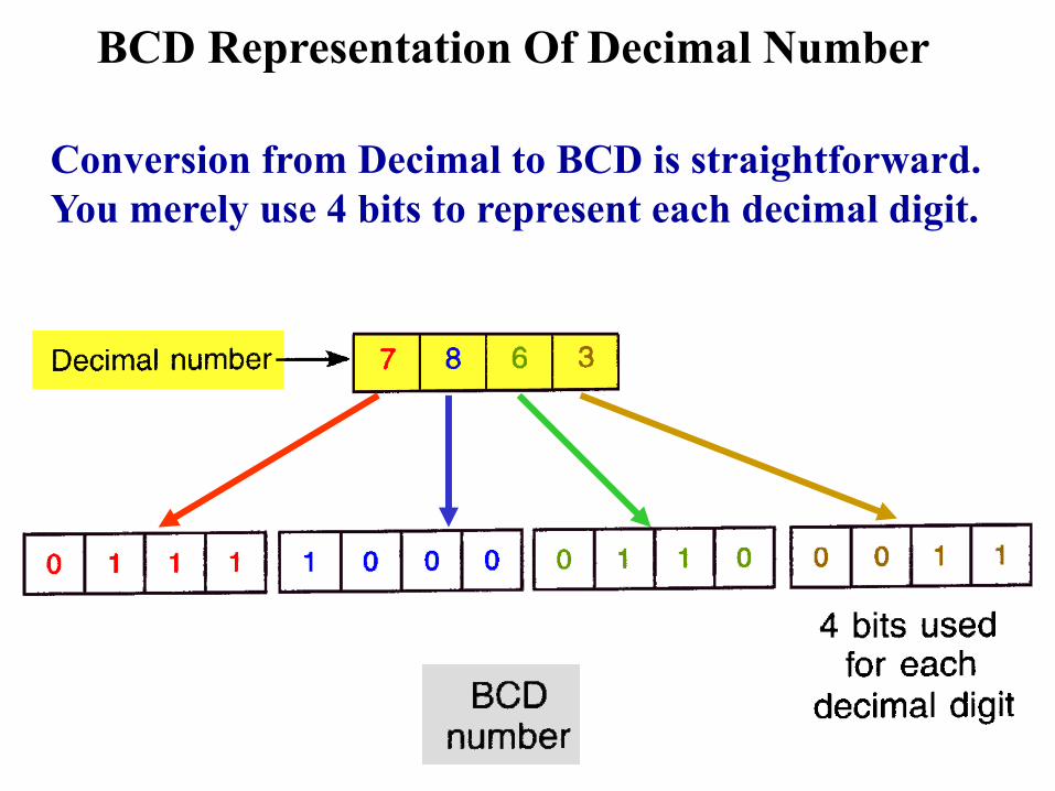
BCD Representation Of Decimal Number
Conversion from Decimal to BCD is straightforward.
You merely use 4 bits to represent each decimal digit.

BCD Thumb-Wheel Switch Interface
The circuit board
has one connection
for each bit’s
weight plus a
common
A decimal number
is selected
The thumb-wheel
switch outputs the
equivalent 4-bits
of BCD data

Typical PLC Number Conversion Instruction
Convert To Decimal Instruction
This instruction will convert the binary bit pattern
at the source address N7:23, into a BCD bit pattern
of the same decimal value as the destination address,
O:20. The instruction executes every time it is scanned
and the instruction is true.
Gray Code
The Gray code is a special type of binary code that does
not use position weighting.
It is set up so that as we progress from one number to
the next, only one bit changes. For this reason, the Gray
code is considered to be an error-minimizing code.
Because only one bit changes at a time, the speed of
transition for the Gray code is considerably faster
than that for codes such as BCD.

Gray Code
Gray codes are used with with position encoders for
accurate control of the motion of robots, machine tools,
and servomechanisms.
Typical Encoder Disk The encoder disk is attached
to a rotating shaft and outputs
a digital Gray code signal that
is used to determine the position
of the shaft.

ASCII Code
ASCII stands for American Standard Code for
Information Interchange. It is an alphanumeric code
because it indicates letters as well as numbers.
The keystrokes
on the keyboard
of a computer are
converted directly
into ASCII for
processing by the
computer.
Parity Bit
Some PLC communications systems use a parity bit
to check the accuracy of data transmission. For example,
when data are transferred between PLCs, one of the
binary bits may accidentally change states.
Parity is a system where each character transmitted
contains one additional bit known as a parity bit. The bit
may be binary 0 or binary 1, depending on the number
of 1’s and 0’s in the character itself.
Two systems of parity are normally used:
odd and even.

Parity Bit Odd parity
means that the
total number of
binary 1 bits in
the character,
including the
parity bit, is odd.
Even parity
means that the
total number of
binary 1 bits in
the character,
including the
parity bit, is even.
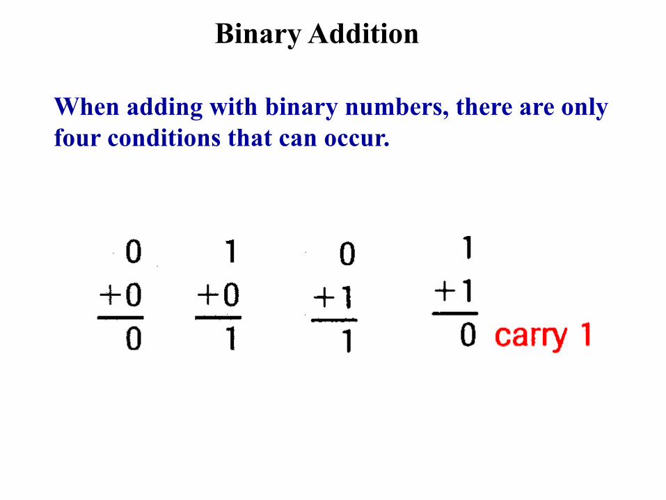
Binary Addition
When adding with binary numbers, there are only
four conditions that can occur.

Binary Addition
When adding larger binary numbers, the resulting
1’s are carried into higher-order columns.

Binary Subtraction
To subtract from larger binary numbers, subtract
column by column, borrowing from the adjacent
column when necessary. Remember that when
borrowing from the adjacent column, there are
two digits, i. e., 0 borrow 1 gives 10.
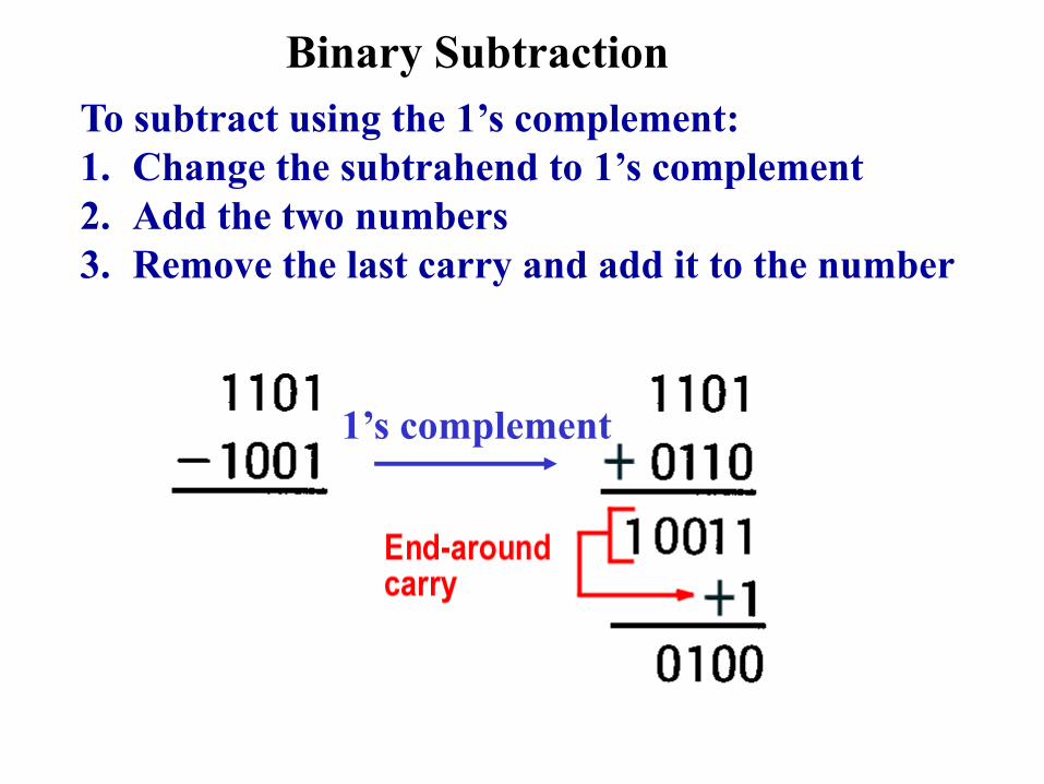
Binary Subtraction
1’s complement
To subtract using the 1’s complement:
1. Change the subtrahend to 1’s complement
2. Add the two numbers
3. Remove the last carry and add it to the number

Binary Multiplication
When multiplying binary numbers, there are only
four conditions that can occur.
0 x 0 = 0
0 x 1 = 0
1 x 0 = 0
1 x 1 = 1
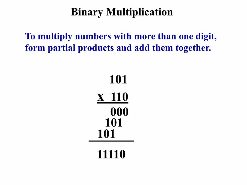
Binary Multiplication
To multiply numbers with more than one digit,
form partial products and add them together.
101
x 110
000 101
101
11110

Binary Division
The process for dividing one binary number by
another is the same for both binary and decimal
numbers.
10 1110
111
10
11
10
10 10
00

Typical PLC Add, Subtract,
Multiply, and Divide Instructions
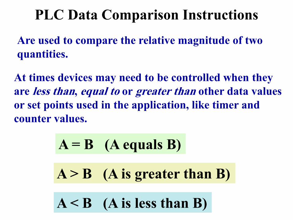
PLC Data Comparison Instructions
Are used to compare the relative magnitude of two
quantities.
At times devices may need to be controlled when they
are less than, equal to or greater than other data values
or set points used in the application, like timer and
counter values.
A = B (A equals B)
A > B (A is greater than B)
A < B (A is less than B)

11. In the binary system + and – symbols are
used to indicate whether a number is positive or
negative. (True/False)
12. Numbers 8 and 9 are not used in the octal
number system. (True/False)
13. The octal number 153 would be written in
binary as:
a. 011 101 001 c. 011 111 101
b. 001 101 011 d. 010 100 011

14. The hexadecimal (hex) numbering system is a
base ______ system.
(a) 2
(b) 8
(c) 10
(d) 16
15. What is the decimal equivalent for the BCD
number 1000 0100 0010 0001?
(a) 8421
(b) 7863
(c) 1234
(d) 3728
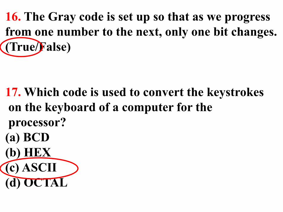
16. The Gray code is set up so that as we progress
from one number to the next, only one bit changes.
(True/False)
17. Which code is used to convert the keystrokes
on the keyboard of a computer for the
processor?
(a) BCD
(b) HEX
(c) ASCII
(d) OCTAL

18. A parity bit is used to check the _______ of data
transmission.
(a) speed
(b) type
(c) accuracy
(d) time
19. What is the sum of binary numbers 1100 and
1011?
a. 10110 c. 10111
b. 11100 d. 00111

20. Which instruction is used to compare the
relative magnitude of two quantities?
(a) Add
(b) Subtract
(c) Multiply
(d) Less Than
Top Related