


Languages
Pages
Legal


Automation & ControlTelemecaniqueThe essential guide
2006

2Other versions: please consult your Schneider Electric agency.
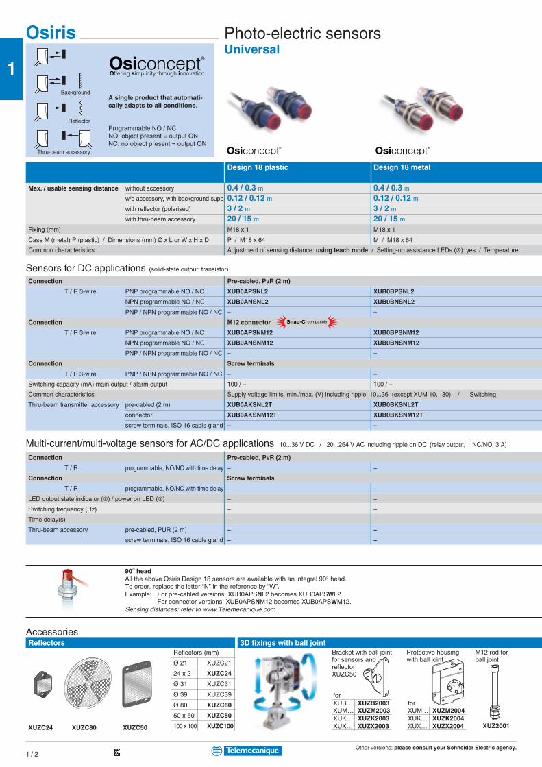
Osiris Photo-electric sensorsUniversal
Design 18 plastic Design 18 metal
Max / usable sensing distance without accessory 0.4 / 0.3 m 0.4 / 0.3 mw/o accessory, with background supp. 0.12 / 0.12 m 0.12 / 0.12 mwith reflector (polarised) 3 / 2 m 3 / 2 mwith thru-beam accessory 20 / 15 m 20 / 15 m
Fixing (mm) M18 x 1 M18 x 1
Case M (metal) P (plastic) / Dimensions (mm) Ø x L or W x H x D P / M18 x 64 M / M18 x 64
Common characteristics Adjustment of sensing distance: using teach mode / Setting-up assistance LEDs (⊗): yes / Temperature
Sensors for DC applications (solid-state output: transistor)
Connection Pre-cabled, PvR (2 m)
T / R 3-wire PNP programmable NO / NC XUB0APSNL2 XUB0BPSNL2
NPN programmable NO / NC XUB0ANSNL2 XUB0BNSNL2
PNP / NPN programmable NO / NC – –
Connection M12 connector
T / R 3-wire PNP programmable NO / NC XUB0APSNM12 XUB0BPSNM12
NPN programmable NO / NC XUB0ANSNM12 XUB0BNSNM12
PNP / NPN programmable NO / NC – –
Connection Screw terminals
T / R 3-wire PNP / NPN programmable NO / NC – –
Switching capacity (mA) main output / alarm output 100 / – 100 / –
Common characteristics Supply voltage limits, min/max (V) including ripple: 10...36 (except XUM 10…30) / Switching
Thru-beam accessory pre-cabled (2 m) XUB0AKSNL2T XUB0BKSNL2T
connector XUB0AKSNM12T XUB0BKSNM12T
screw terminals, ISO 16 cable gland – –
Multi-current/multi-voltage sensors for AC/DC applications 10...36 V DC / 20...264 V AC including ripple on DC (relay output, 1 C/O, 3 A)
Connection Pre-cabled, PvR (2 m)
T / R programmable, NO/NC with time delay – –
Connection Screw terminals
T / R programmable, NO/NC with time delay – –
LED output state indicator (⊗) / power on LED (⊗) – –
Switching frequency (Hz) – –
Time delay(s) – –
Thru-beam accessory pre-cabled, PUR (2 m) – –
screw terminals, ISO 16 cable gland – –
A single product that automati-cally adapts to all conditions.
Programmable NO / NCNO: object present = output ONNC: no object present = output ON
Snap-C® compatible
AccessoriesReflectors
XUZC24 XUZC80 XUZC50
3D fixings with ball jointReflectors (mm)
Ø 21 XUZC21
24 x 21 XUZC24
Ø 31 XUZC31
Ø 39 XUZC39
Ø 80 XUZC80
50 x 50 XUZC50
100 x 100 XUZC100
90° headAll the above Osiris Design 18 sensors are available with an integral 90° head.To order, replace the letter “N” in the reference by “W”.Example: For pre-cabled versions: XUB0APSNL2 becomes XUB0APSWL2.
For connector versions: XUB0APSNM12 becomes XUB0APSWM12.Sensing distances: refer to www.Telemecanique.com
Bracket with ball jointfor sensors andreflectorXUZC50
forXUM… XUZM2004XUK… XUZK2004XUX… XUZX2004
forXUB… XUZB2003XUM… XUZM2003XUK… XUZK2003XUX… XUZX2003 XUZ2001
Protective housingwith ball joint
M12 rod forball joint
Background
Reflector
Thru-beam accessory
Also available in Design 18 metal,
2-wire type multi-current/multi-voltage
AC/DC version. Please refer to
www.Telemecanique .com
2
AccessoiresRéflecteurs
XUZC24 XUZC80 XUZC50
Click on the icon and straight awayyou will get the web sheet for theproduct corresponding to that page.
New, icons at the bottom of the pagesin your essential guide!
Simply click on this icon to obtain direct access toall the information that interests you, on anyproduct, via the website:www.telemecanique.com
This way you can easily access froma product sheet the following items:b the electronic catalogueb the website dedicated to thatproductb a comprehensive library in whichyou will find brochures, catalogues,technical documentation (userguides, technical manuals, etc.)linked to that particular product.
New telemecanique.com portal
This international site allows you to access all the Telemecanique productsin just 2 clicks via comprehensive range data-sheets, with direct links to:b Complete library : technical documents, catalogs, certificates, FAQs,brochures...b Selection guides from the e-catalogb Product discovery sites and their Flash animations
You will also find illustrated overviews, news to which you can subscribe,a discussion forum, the list of country contacts...To live automation solutions every day!
Product index Functions Product data-sheet E-catalog Librarydiscovery
How to proceed
b To order the clicker (reader), pleaseconsult your Sales Office(reference: DIA1GD0040601 - art: 960013)
b Click on the icon printedat the bottom of the pages
b The product sheet corresponding to the pagethen opens automatically with all the informationrelating to that product, therefore saving you aconsiderable amount of research time.
Detectionb Photo-electric sensorsb Inductive proximity sensorsb Limit switchesb Sensors for pressure control
Operator dialogb Control and signalling unitsb Human-Machine Interfaces
Automationb Relaysb Programmable controllers & Automation platformsb Distributed Inputs/Outputs
Motion and Drivesb Soft startersb Variable speed drivesb Motion modulesb Lexium servo drives for SER, BPH and BPL servo motors
Motor controlb Motor control componentsb Components for power control applications
Power suppliesPower supplies and transformers for control circuits
Interfaces and I/Ob Connectionb Interfaces and distributed Inputs/Outputs
AS-Interface cabling systemb The cabling system that meets your needs for industrial automationsystems
Machine safetyb Safety solutions provide maximum protection in all the safetyfunctions of your automation system
Explosive atmospheresb Detectionb Control and signalling unitsb Machine safetyb Automation
Schneider worldwideb Address
2
3
4
5
6
7
8
9
10
1G
ener
al c
onte
nts
I ntroductionTelemecanique,b the SchneiderElectric brand forAutomation & Control.b innovativeproducts…
Interfaces & I/O
Systems & Architectures
Software tools
Mounting systems
Power supplies
Motion and Drives
Detection
Automation
Operator dialog
Motor control
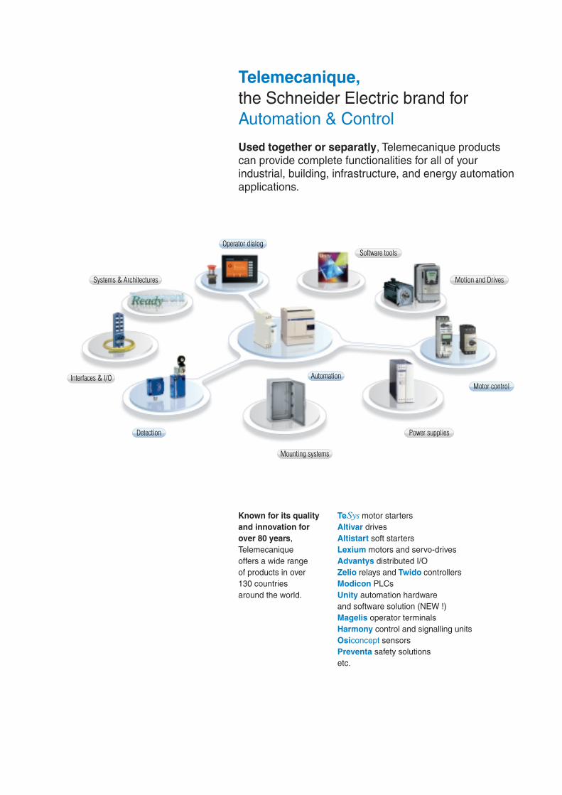
Telemecanique,the Schneider Electric brand forAutomation & Control
Used together or separatly, Telemecanique productscan provide complete functionalities for all of yourindustrial, building, infrastructure, and energy automationapplications.
TeSys motor startersAltivar drivesAltistart soft startersLexium motors and servo-drivesAdvantys distributed I/OZelio relays and Twido controllersModicon PLCsUnity automation hardwareand software solution (NEW !)Magelis operator terminalsHarmony control and signalling unitsOsiconcept sensorsPreventa safety solutionsetc.
Known for its qualityand innovation forover 80 years,Telemecaniqueoffers a wide rangeof products in over130 countriesaround the world.
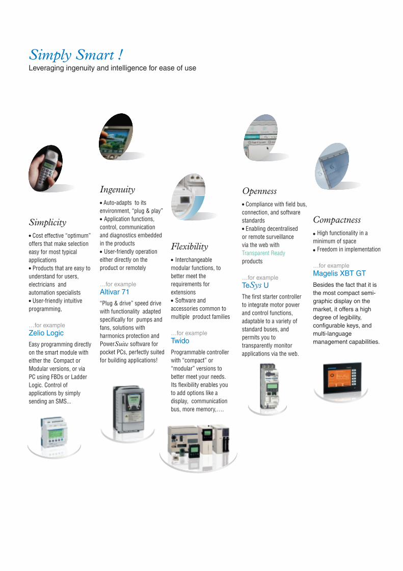
Simply Smart !Leveraging ingenuity and intelligence for ease of use
Simplicityp Cost effective “optimum”offers that make selectioneasy for most typicalapplicationsp Products that are easy tounderstand for users,electricians andautomation specialistsp User-friendly intuitiveprogramming,
…for exampleZelio Logic
Easy programming directlyon the smart module witheither the Compact orModular versions, or viaPC using FBDs or LadderLogic. Control ofapplications by simplysending an SMS...
Ingenuityp Auto-adapts to itsenvironment, “plug & play”p Application functions,control, communicationand diagnostics embeddedin the productsp User-friendly operationeither directly on theproduct or remotely
…for exampleAltivar 71
“Plug & drive” speed drivewith functionality adaptedspecifically for pumps andfans, solutions withharmonics protection andPowerSuite software forpocket PCs, perfectly suitedfor building applications!
Flexibilityp Interchangeablemodular functions, tobetter meet therequirements forextensionsp Software andaccessories common tomultiple product families
…for exampleTwido
Programmable controllerwith “compact” or“modular” versions tobetter meet your needs.Its flexibility enables youto add options like adisplay, communicationbus, more memory,….
Opennessp Compliance with field bus,connection, and softwarestandardsp Enabling decentralisedor remote surveillancevia the web withTransparent Readyproducts
…for exampleTeSys UThe first starter controllerto integrate motor powerand control functions,adaptable to a variety ofstandard buses, andpermits you totransparently monitorapplications via the web.
Compactnessp High functionality in aminimum of spacep Freedom in implementation
…for exampleMagelis XBT GT
Besides the fact that it isthe most compact semi-graphic display on themarket, it offers a highdegree of legibility,configurable keys, andmulti-languagemanagement capabilities.

Detection
Interfaces & I/O
Mounting systems
Systems & Architectures
Operator dialog
Machine safety
AS-Interface
Telemecanique,innovative products for all Automation & Control functions.
Operator dialog
Control & signalling unitsControl and signalling units,cam switchesBeacons and indicator banks
Human machine interfacesOperator interface terminals,industrial PCs, Web servers,HMI and SCADA PC-basedsoftware
Control stations, mountingsolutionsControl and pendantstations, front panelsmounting kits
AS-InterfaceControl stations, keypads,beacons
Machine safetyEmergency stops, controlstations, enabling switches,foot switches
SoftwareOperator terminal software
Interfaces & I/O
ConnectorsCable-ends, terminal blocs
InterfacesPlug-in relays, analogconverters, discreteinterfacesPre-wired interfaces,IP20/IP67 distributed I/O
AS-InterfaceIP20/IP67 interfaces,cables, repeaters,accessories,adressing andadjustment terminals
Machine safetySafety monitors andcontrollers on AS-Interface
SoftwareSoftware to design andinstall AS-Interface system,safety monitors andcontrollers on AS-Interfaceprogramming software
Systems &Architectures
Connecting Ethernetdevices
Web-enabling PLCson Ethernet
Application protocolsand field buses
Mounting systems
EnclosuresWall mounted enclosuresFloor standing enclosures,suite type cubiclesIndustrial boxes
Equipment and accessoriesThermal control equipmentPower splitter blocksMounting accessories
Detection
SensorsLimit switchesProximity sensorsPhoto-electric and ultrasonicsensorsPressure switchesRotary encoders
RFID, visionInductive identificationVision system
Machine safetySwitches, light curtains,mats
SoftwareSafety mats configurationsoftware
See Machine safetyin each function
See AS-Interfacein each function

Automation
Motion and Drives
Motor control
Power supplies
Software tools
Automation
RelaysPlug-in relays, electronictimers, control relays,countsSmart relays
PLCs, PC based control,distributed I/OProgrammable controllersPLC platformsPC based controlDistributed I/O, I/Ocontrollers
AS-InterfaceMaster modules forModicon PLCs
Machine safetySafety PLCs, controllersand modules
SoftwarePLCs and safety controllersprogramming software
Software tools
Global softwareGeneration of applicationsystemsApplication controlCollaborative development
Dedicated softwareSee Software in otherfunctions
Motion and Drives
Starters, drives andservo drivesSoft startersVariable speed drivesMotion modulesServo drivesServo motors
SoftwareSoftware for drivesand motors
Motor control
Motor startersContactorsCircuit breakers, fuse carriersThermal relaysCombinations, motorcontrollers
Mounting solutionsMotor starter mounting kit
AS-InterfaceMotor controllers,enclosures, variable speeddrives
Machine safetySwitch disconnectors,thermal-magnetic motorcircuit breakers, enclosedstarters
SoftwareMotor control programmingsoftware
Power supplies
Power suppliesSwitch mode powersuppliesFiltered rectified powersupplies, transformers
AS-InterfacePower supplies
Simply Smart !
Det
ectio
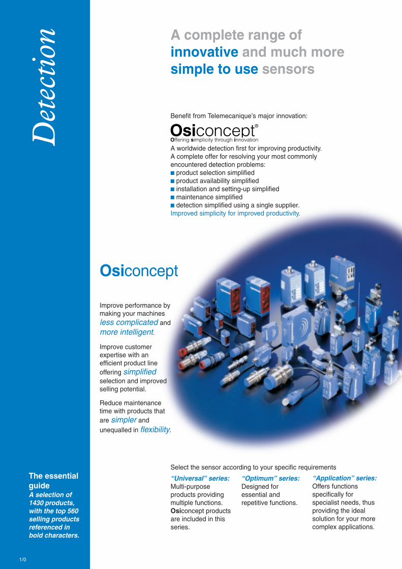
n A complete range ofinnovative and much moresimple to use sensors
Benefit from Telemecanique’s major innovation:
A worldwide detection first for improving productivity.A complete offer for resolving your most commonlyencountered detection problems:b product selection simplifiedb product availability simplifiedb installation and setting-up simplifiedb maintenance simplifiedb detection simplified using a single supplier.Improved simplicity for improved productivity.
Osiconcept
Improve performance bymaking your machinesless complicated andmore intelligent.
Improve customerexpertise with anefficient product lineoffering simplifiedselection and improvedselling potential.
Reduce maintenancetime with products thatare simpler andunequalled in flexibility.
“Universal” series:Multi-purposeproducts providingmultiple functions.Osiconcept productsare included in thisseries.
“Optimum” series:Designed foressential andrepetitive functions.
“Application” series:Offers functionsspecifically forspecialist needs, thusproviding the idealsolution for your morecomplex applications.
Select the sensor according to your specific requirementsThe essentialguideA selection of1430 products,with the top 560selling productsreferenced inbold characters.
1/0

> A single product thatautomatically adapts toall conditions
> A single product thatautomatically adapts toall installation environ-ments
> Availability of morethan 5,000 interchange-able configurationswithin 24 hours
> A user-friendly productat last; easy to parameterprior to installation andto modify duringoperation
> A single product thatautomatically learnsboth its detection modeand detection zone
> Simple parameteringof many differentresolutions on the sameproduct
1/1
1Contents
b Osiris Photo-electric sensors ........................... 1/2 to 1/13
Detection without contact of objectswhatever their shape or material> Detection from a few millimetres to severaltens of metres> 3D adjustable fixing accessories> Specific products for particular applications
b Osiprox Inductive proximity sensors .......... 1/14 to 1/24
Detection without contact of metal objects> Sensor / object distance ≤ 60 mm> Generic cylindrical and flat form products> Specific products for particular applications
b Osisonic Ultrasonic sensors ..................... 1/26 and 1/27
Detection without contact of any object of any material> Detection from a few millimetres up to 8 metres> Extra large range to ensure finding the right product> Specific products for particular applications
b Osicoder Rotary encoders ..................... 1/28 and 1/29
Opto-electronic detection> Incremental> Absolute - single turn and multiturn> PROFIBUS and CANopen fieldbus communicating
b Osiswitch Limit switches .............................. 1/30 to 1/39
Detection by contact of rigid objects> Positive opening operation of electrical contacts> Object speed ≤ 1.5 m/s> Specific products for particular applications
b Nautilus Sensors for pressure control ....... 1/40 to 1/45
Detection by contact with fluid> Electronic pressure and vacuum switches> Analogue pressure sensors> Electromechanical pressure and vacuum switches
Other detection technologies
b Osiprox Capacitive proximity sensors ................... 1/25
b Osiview Vision system ............................................... 1/46Complete industrial vision system comprising:controllers, lenses, cameras, lighting systems, accessories, etc.
b Inductel Inductive identification .......................... 1/47Complete inductive identification system provided bya complete range of tags, inductive heads and stations
b Sensors for explosive atmospheres(see chapter 10 “Explosive Atmospheres”)
Other versions: please consult your Schneider Electric agency.1 / 2
1
Osiris Photo-electric sensorsUniversal
Design 18 plastic Design 18 metal
Max. / usable sensing distance without accessory 0.4 / 0.3 m 0.4 / 0.3 mw/o accessory, with background supp. 0.12 / 0.12 m 0.12 / 0.12 mwith reflector (polarised) 3 / 2 m 3 / 2 mwith thru-beam accessory 20 / 15 m 20 / 15 m
Fixing (mm) M18 x 1 M18 x 1
Case M (metal) P (plastic) / Dimensions (mm) Ø x L or W x H x D P / M18 x 64 M / M18 x 64
Common characteristics Adjustment of sensing distance: using teach mode / Setting-up assistance LEDs (⊗): yes / Temperature
Sensors for DC applications (solid-state output: transistor)
Connection Pre-cabled, PvR (2 m)
T / R 3-wire PNP programmable NO / NC XUB0APSNL2 XUB0BPSNL2
NPN programmable NO / NC XUB0ANSNL2 XUB0BNSNL2
PNP / NPN programmable NO / NC – –
Connection M12 connector
T / R 3-wire PNP programmable NO / NC XUB0APSNM12 XUB0BPSNM12
NPN programmable NO / NC XUB0ANSNM12 XUB0BNSNM12
PNP / NPN programmable NO / NC – –
Connection Screw terminals
T / R 3-wire PNP / NPN programmable NO / NC – –
Switching capacity (mA) main output / alarm output 100 / – 100 / –
Common characteristics Supply voltage limits, min./max. (V) including ripple: 10...36 (except XUM 10…30) / Switching
Thru-beam transmitter accessory pre-cabled (2 m) XUB0AKSNL2T XUB0BKSNL2T
connector XUB0AKSNM12T XUB0BKSNM12T
screw terminals, ISO 16 cable gland – –
Multi-current/multi-voltage sensors for AC/DC applications 10...36 V DC / 20...264 V AC including ripple on DC (relay output, 1 NC/NO, 3 A)
Connection Pre-cabled, PvR (2 m)
T / R programmable, NO/NC with time delay – –
Connection Screw terminals
T / R programmable, NO/NC with time delay – –
LED output state indicator (⊗) / power on LED (⊗) – –
Switching frequency (Hz) – –
Time delay(s) – –
Thru-beam accessory pre-cabled, PUR (2 m) – –
screw terminals, ISO 16 cable gland – –
A single product that automati-cally adapts to all conditions.
Programmable NO / NCNO: object present = output ONNC: no object present = output ON
Snap-C® compatible
AccessoriesReflectors
XUZC24 XUZC80 XUZC50
3D fixings with ball jointReflectors (mm)
Ø 21 XUZC21
24 x 21 XUZC24
Ø 31 XUZC31
Ø 39 XUZC39
Ø 80 XUZC80
50 x 50 XUZC50
100 x 100 XUZC100
90° headAll the above Osiris Design 18 sensors are available with an integral 90° head.To order, replace the letter “N” in the reference by “W”.Example: For pre-cabled versions: XUB0APSNL2 becomes XUB0APSWL2.
For connector versions: XUB0APSNM12 becomes XUB0APSWM12.Sensing distances: refer to www.Telemecanique.com
Bracket with ball jointfor sensors andreflectorXUZC50
forXUM… XUZM2004XUK… XUZK2004XUX… XUZX2004
forXUB… XUZB2003XUM… XUZM2003XUK… XUZK2003XUX… XUZX2003 XUZ2001
Protective housingwith ball joint
M12 rod forball joint
Background
Reflector
Thru-beam accessory

Other versions: please consult your Schneider Electric agency.1 / 3
1
Snap-C® compatible
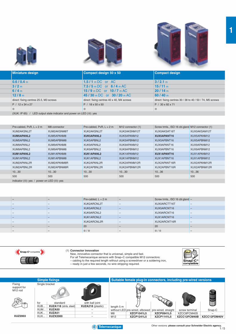
Miniature design Compact design 50 x 50 Compact design
0.55 / 0.4 m 1.2 / 0.8 m 3 / 2 m0.10 / 0.10 m 0.3 / 0.3 m 1.3 / 1.3 m4 / 3 m 5.7 / 4 m 15 / 11 m14 / 10 m 35 / 30 m 60 / 40 mdirect: fixing centres 25.5, M3 screws direct: fixing centres 40 x 40, M4 screws direct: fixing centres 30 / 38 to 40 / 50 / 74, M5 screws
P / 12 x 34 x 20 P / 18 x 50 x 50 P / 30 x 92 x 71
range (°C): - 25…+ 55 / Degree of protection (conforming to IEC 60529): IP 65, IP 67 (XUK: IP 65)
XUM0APSAL2 – –
XUM0ANSAL2 – –
– XUK0AKSAL2 –
M8 connector M12 connector
XUM0APSAM8 (1) – –
XUM0ANSAM8 (1) – –
– XUK0AKSAM12 XUX0AKSAM12
– – XUX0AKSAT16
100 / 50 100 / 50 100 / 100
frequency (Hz): 250 / Overload and short-circuit protection () / LED output state indicator (⊗): yes / power on LED (⊗): yes
XUM0AKSAL2T XUK0AKSAL2T –
XUM0AKSAM8T (1) XUK0AKSAM12T XUX0AKSAM12T
– – XUX0AKSAT16T
– XUK0ARCTL2 –
– – XUX0ARCTT16
– ⊗ / ⊗ ⊗ / ⊗– 20 20
– Adjustment from 0 to 15 s, on energisation, on de-energisation or monostable
– XUK0ARCTL2T –
– – XUX0ARCTT16T
length 5 mwithout LED pre-wired, elbowed pre-wired, straight screw terminal Snap-CM8 XZCP1041L5 XZCP0941L5 XZCC8FCM40S –M12 XZCP1241L5 XZCP1141L5 XZCC12FCM40B XZCC12FDM40V
Connector innovationNew, innovative connector that is universal, simple and fast.For all Telemecanique sensors with Snap–C compatible M12 connectors:
– cabling to the required length without using a screwdriver or a soldering iron,– ready in just a few seconds, no wire stripping required.
Suitable female plug-in connectors, including pre-wired versions
XUZ2003
Fixingsupport forM12 rod
Single bracket
for standard with ball jointXUB... XUZA118 (stnls. steel) XUZA218 (plastic)XUM... XUZA50 –XUK... XUZA51 –XUX... XUZX2000 –
(1) M8 not Snap–C® compatible.
Simple fixings
Snap-C® compatible

Other versions: please consult your Schneider Electric agency.1 / 4
1
Photo-electric sensorsOptimum
Design 18 plastic Design 18 metal
Max. / usable sensing distance Diffuse 0.8 / 0.6 m 0.8 / 0.6 mPolarised reflex 3 / 2 m 3 / 2 mReflex 5.5 / 4 m 5.5 / 4 mThru-beam 20 / 15 m 20 / 15 m
Fixing (mm) M18 x 1 M18 x 1
Case M (metal) P (plastic) / Dimensions (mm) Ø x L or W x H x D P / M18 x 46 M / M18 x 46
Setting-up assistance LEDs ⊗ – –
Common characteristics Temperature range (°C): - 25…+ 55 / Degree of protection (conforming to IEC 60529): IP 65, IP 67
Sensors for DC applications (solid-state output: transistor)
Connection Pre-cabled, PvR, L = 2 m M12 connector (1) Pre-cabled, PvR, L = 2 m M12 connector (1)
Transmitter XUB2AKSNL2T XUB2AKSNM12T XUB2BKSNL2T XUB2BKSNM12T
Receiver or T/R, 3-wire PNP (1) Diffuse, adjustable NO XUB5APANL2 XUB5APANM12 XUB5BPANL2 XUB5BPANM12
NC XUB5APBNL2 XUB5APBNM12 XUB5BPBNL2 XUB5BPBNM12
Polarised reflex NO XUB9APANL2 XUB9APANM12 XUB9BPANL2 XUB9BPANM12
NC XUB9APBNL2 XUB9APBNM12 XUB9BPBNL2 XUB9BPBNM12
Reflex NO XUB1APANL2 XUB1APANM12 XUB1BPANL2 XUB1BPANM12
NC XUB1APBNL2 XUB1APBNM12 XUB1BPBNL2 XUB1BPBNM12
Thru-beam NO XUB2APANL2R XUB2APANM12R XUB2BPANL2R XUB2BPANM12R
NC XUB2APBNL2R XUB2APB NM12R XUB2BPBNL2R XUB2BPBNM12R
Supply voltage limits, min./max. (V) including ripple 10...36 10...36 10...36 10...36
Switching frequency (Hz) 500 500 500 500
Common characteristics for DC versions Switching capacity, max. (mA): 100 / Overload and short-circuit protection () / LED output state
(1) For versions with NPN output, replace “P” by “N”. Example: XUB1APANL2 becomes XUB1ANANL2.
Multi-current/multi-voltage sensors for AC/DC applications 10…36 V DC / 20…264 V AC including ripple on DC (relay output, 1 NC/NO, 3 A)
Connection – – – –
Transmitter – – – –
Receiver or T/R Diffuse NO + NC – – –
Polarised reflex NO + NC – – –
Reflex NO + NC – – –
Thru-beam NO + NC – – – –
Switching frequency (Hz) – – – –
LED output state indicator (⊗) / power on LED (⊗) – – – –
AccessoriesReflectors
XUZC24 XUZC80 XUZC50
3D fixings with ball jointBracket with ball jointfor sensors andreflectorXUZC50
forXUM… XUZM2004XUK… XUZK2004XUX… XUZX2004
forXUB… XUZB2003XUM… XUZM2003XUK… XUZK2003XUX… XUZX2003 XUZ2001
Protective housingwith ball joint
M12 rod forball joint
Reflectors (mm)
Ø 21 XUZC21
24 x 21 XUZC24
Ø 31 XUZC31
Ø 39 XUZC39
Ø 80 XUZC80
50 x 50 XUZC50
100 x 100 XUZC100
90° headAll the above Osiris Design 18 sensors are available with an integral 90° head.To order, replace the letter “N” in the reference by “W”.Example: For pre-cabled versions: XUB0APSNL2 becomes XUB0APSWL2.
For connector versions: XUB0APSNM12 becomes XUB0APSWM12.Sensing distances: refer to www.Telemecanique.com
Object present detection NO Output ON / object presentThru-beam Reflex Diffuse
(T) (R) (T/R) (T/R)
No object present detection NC Output ON / no object presentThru-beam Reflex Diffuse
(T) (R) (T/R) (T/R)
Osiris
Also available in Design 18, 2-wire
type multi-current/multi-voltage
a.c./d.c. version. Please refer to
www.Telemecanique .com
Other versions: please consult your Schneider Electric agency.1 / 5
1
Snap-C® compatible
Miniature design Compact design 50 x 50 Compact design
0.6 / 0.4 m 1.5 / 1 m DC or AC 3 / 2.1 m3 / 2 m 7.5 / 5 m DC or 6 / 4 m AC 15 / 11 m6 / 4 m 15 / 9 m DC or 10 / 7 m AC 20 / 14 m12 / 8 m 45 / 30 m DC or 30 / 20 m AC 60 / 40 mdirect: fixing centres 25.5, M3 screws direct: fixing centres 40 x 40, M4 screws direct: fixing centres 30 / 38 to 40 / 50 / 74, M5 screws
P / 12 x 34 x 27 P / 18 x 50 x 50 P / 30 x 92 x 71
⊗ ⊗ ⊗(XUK: IP 65) / LED output state indicator and power on LED (⊗): yes
Pre-cabled, PvR, L = 2 m M8 connector Pre-cabled, PvR, L = 2 m M12 connector (1) Screw trmls., ISO 16 cbl.gland M12 connector (1)
XUM2AKSNL2T XUM2AKSNM8T XUK2AKSNL2T XUK2AKSNM12T XUX0AKSAT16T XUX0AKSAM12T
XUM5APANL2 XUM5APANM8 XUK5APANL2 XUK5APANM12 XUX5APANT16 XUX5APANM12
XUM5APBNL2 XUM5APBNM8 XUK5APBNL2 XUK5APBNM12 XUX5APBNT16 XUX5APBNM12
XUM9APANL2 XUM9APANM8 XUK9APANL2 XUK9APANM12 XUX9APANT16 XUX9APANM12
XUM9APBNL2 XUM9APBNM8 XUK9APBNL2 XUK9APBNM12 XUX9APBNT16 XUX9APBNM12
XUM1APANL2 XUM1APANM8 XUK1APANL2 XUK1APANM12 XUX1APANT16 XUX1APANM12
XUM1APBNL2 XUM1APBNM8 XUK1APBNL2 XUK1APBNM12 XUX1APBNT16 XUX1APBNM12
XUM2APANL2R XUM2APANM8R XUK2APANL2R XUK2APANM12R XUX2APANT16R XUX2APANM12R
XUM2APBNL2R XUM2APBNM8R XUK2APBNL2R XUK2APBNM12R XUX2APBNT16R XUX2APBNM12R
10...30 10...30 10...30 10...30 10...36 10...36
500 500 500 500 500 500
indicator (⊗): yes / power on LED (⊗): yes
– – Pre-cabled, L = 2 m – Screw trmls., ISO 16 cbl.gland –
– – XUK2ARCNL2T – XUX0ARCTT16T –
– – XUK5ARCNL2 – XUX5ARCNT16 –
– – XUK9ARCNL2 – XUX9ARCNT16 –
– – XUK1ARCNL2 – XUX1ARCNT16 –
– – XUK2ARCNL2R – XUX2ARCNT16R –
– – 20 – 20 –
– – ⊗ / ⊗ – ⊗ / ⊗ –
length 5 mwithout LED pre-wired, elbowed pre-wired, straight screw terminal Snap-CM8 XZCP1041L5 XZCP0941L5 XZCC8FCM40S –M12 XZCP1241L5 XZCP1141L5 XZCC12FCM40B XZCC12FDM40V
Suitable female plug-in connectors, including pre-wired versions
XUZ2003
Fixingsupport forM12 rod
Single bracket
for standard with ball jointXUB... XUZA118 (stnls. steel) XUZA218 (plastic)XUM... XUZA50 –XUK... XUZA51 –XUX... XUZX2000 –
Simple fixings
(1) Connector innovationNew, innovative connector that is universal, simple and fast.For all Telemecanique sensors with Snap–C compatible M12 connectors:– cabling to the required length without using a screwdriver or a soldering iron,– ready in just a few seconds, no wire stripping required.
Other versions: please consult your Schneider Electric agency.1 / 6
1
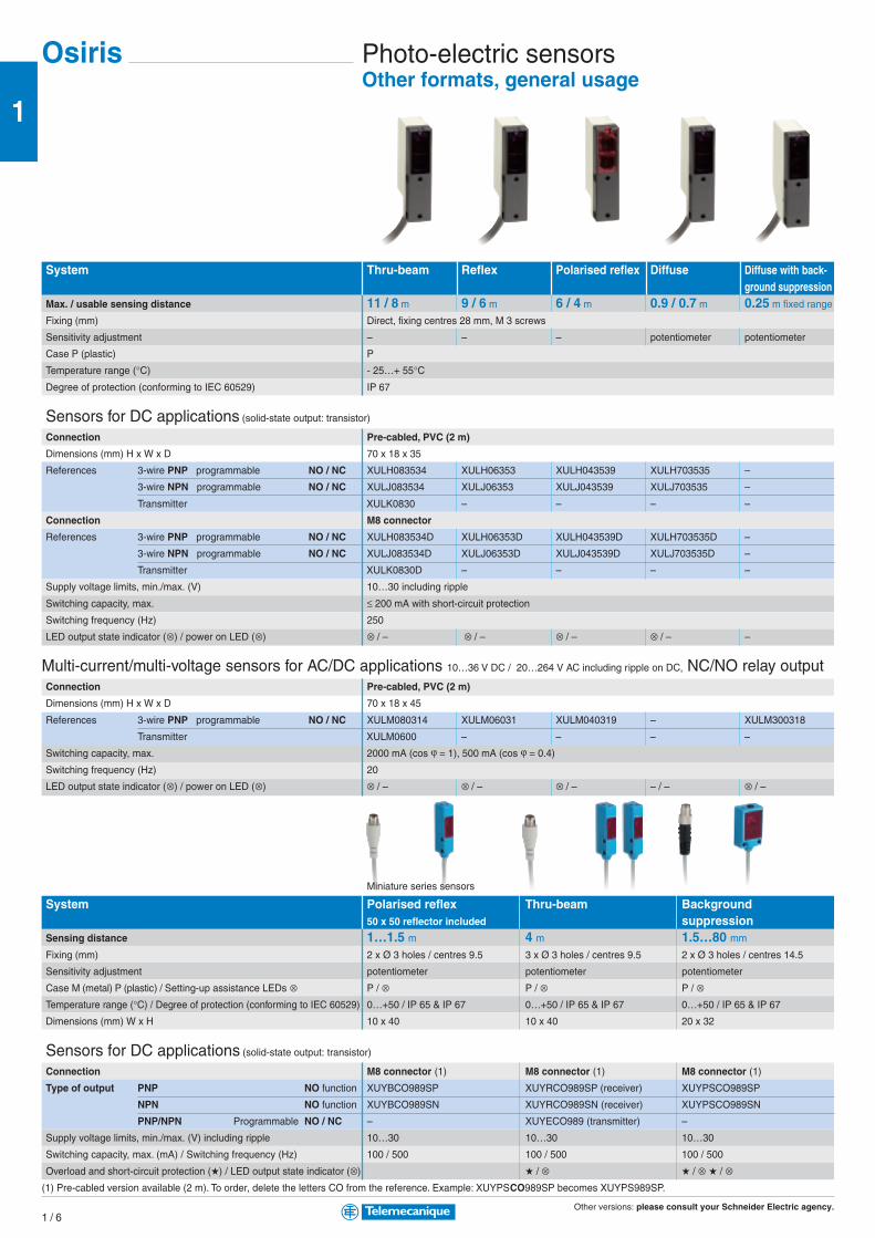
Photo-electric sensorsOther formats, general usage
Osiris
System Thru-beam Reflex Polarised reflex Diffuse Diffuse with back-ground suppression
Max. / usable sensing distance 11 / 8 m 9 / 6 m 6 / 4 m 0.9 / 0.7 m 0.25 m fixed range
Fixing (mm) Direct, fixing centres 28 mm, M 3 screws
Sensitivity adjustment – – – potentiometer potentiometer
Case P (plastic) P
Temperature range (°C) - 25…+ 55°CDegree of protection (conforming to IEC 60529) IP 67
Sensors for DC applications (solid-state output: transistor)
Connection Pre-cabled, PVC (2 m)
Dimensions (mm) H x W x D 70 x 18 x 35
References 3-wire PNP programmable NO / NC XULH083534 XULH06353 XULH043539 XULH703535 –
3-wire NPN programmable NO / NC XULJ083534 XULJ06353 XULJ043539 XULJ703535 –
Transmitter XULK0830 – – – –
Connection M8 connector
References 3-wire PNP programmable NO / NC XULH083534D XULH06353D XULH043539D XULH703535D –
3-wire NPN programmable NO / NC XULJ083534D XULJ06353D XULJ043539D XULJ703535D –
Transmitter XULK0830D – – – –
Supply voltage limits, min./max. (V) 10…30 including ripple
Switching capacity, max. ≤ 200 mA with short-circuit protection
Switching frequency (Hz) 250
LED output state indicator (⊗) / power on LED (⊗) ⊗ / – ⊗ / – ⊗ / – ⊗ / – –
Multi-current/multi-voltage sensors for AC/DC applications 10…36 V DC / 20…264 V AC including ripple on DC, NC/NO relay outputConnection Pre-cabled, PVC (2 m)
Dimensions (mm) H x W x D 70 x 18 x 45
References 3-wire PNP programmable NO / NC XULM080314 XULM06031 XULM040319 – XULM300318
Transmitter XULM0600 – – – –
Switching capacity, max. 2000 mA (cos ϕ = 1), 500 mA (cos ϕ = 0.4)
Switching frequency (Hz) 20
LED output state indicator (⊗) / power on LED (⊗) ⊗ / – ⊗ / – ⊗ / – – / – ⊗ / –
Miniature series sensors
System Polarised reflex Thru-beam Background50 x 50 reflector included suppression
Sensing distance 1…1.5 m 4 m 1.5…80 mm
Fixing (mm) 2 x Ø 3 holes / centres 9.5 3 x Ø 3 holes / centres 9.5 2 x Ø 3 holes / centres 14.5
Sensitivity adjustment potentiometer potentiometer potentiometer
Case M (metal) P (plastic) / Setting-up assistance LEDs ⊗ P / ⊗ P / ⊗ P / ⊗Temperature range (°C) / Degree of protection (conforming to IEC 60529) 0…+50 / IP 65 & IP 67 0…+50 / IP 65 & IP 67 0…+50 / IP 65 & IP 67
Dimensions (mm) W x H 10 x 40 10 x 40 20 x 32
Sensors for DC applications (solid-state output: transistor)
Connection M8 connector (1) M8 connector (1) M8 connector (1)
Type of output PNP NO function XUYBCO989SP XUYRCO989SP (receiver) XUYPSCO989SP
NPN NO function XUYBCO989SN XUYRCO989SN (receiver) XUYPSCO989SN
PNP/NPN Programmable NO / NC – XUYECO989 (transmitter) –
Supply voltage limits, min./max. (V) including ripple 10…30 10…30 10…30
Switching capacity, max. (mA) / Switching frequency (Hz) 100 / 500 100 / 500 100 / 500
Overload and short-circuit protection () / LED output state indicator (⊗) / ⊗ / ⊗ / ⊗(1) Pre-cabled version available (2 m). To order, delete the letters CO from the reference. Example: XUYPSCO989SP becomes XUYPS989SP.
Other versions: please consult your Schneider Electric agency.1 / 7
1
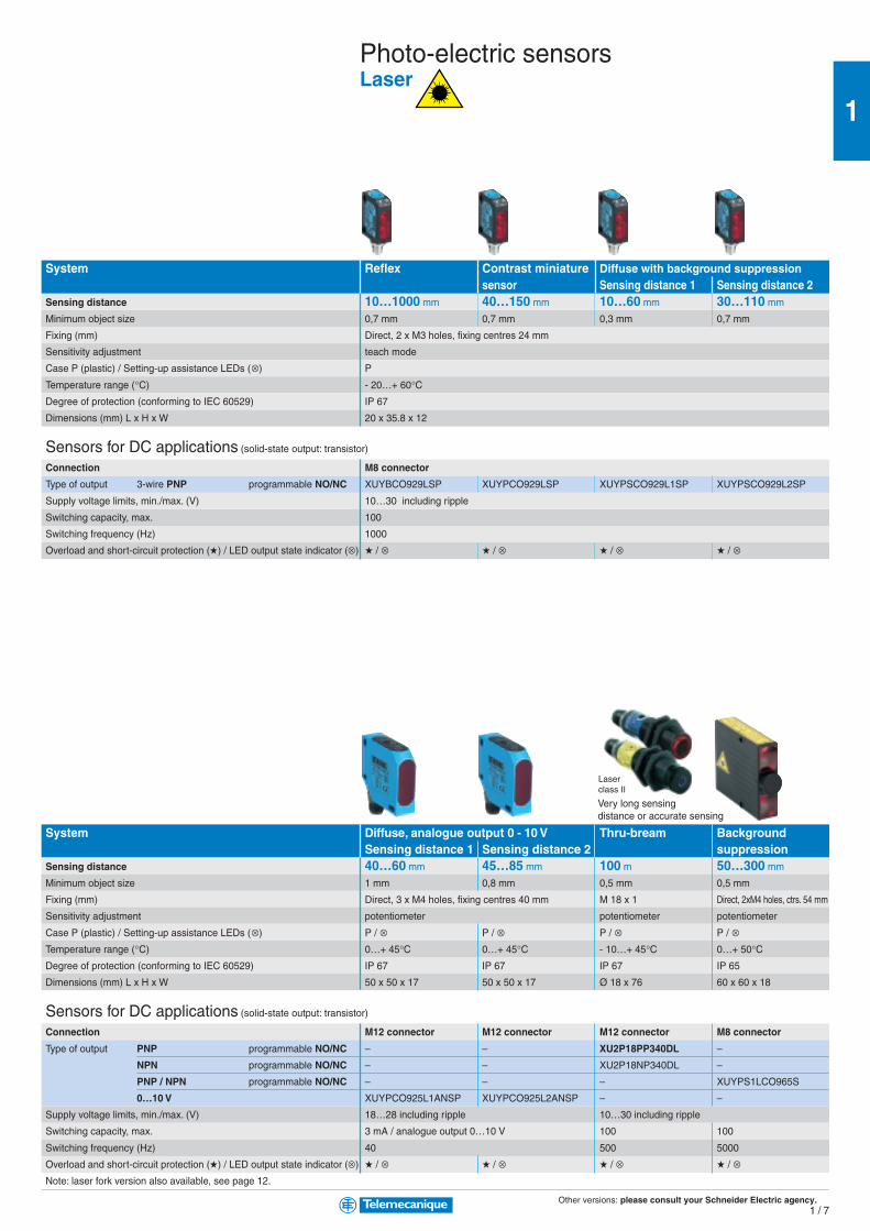
Photo-electric sensorsLaser
System Reflex Contrast miniature Diffuse with background suppressionsensor Sensing distance 1 Sensing distance 2
Sensing distance 10…1000 mm 40…150 mm 10…60 mm 30…110 mm
Minimum object size 0,7 mm 0,7 mm 0,3 mm 0,7 mm
Fixing (mm) Direct, 2 x M3 holes, fixing centres 24 mm
Sensitivity adjustment teach mode
Case P (plastic) / Setting-up assistance LEDs (⊗) P
Temperature range (°C) - 20…+ 60°CDegree of protection (conforming to IEC 60529) IP 67
Dimensions (mm) L x H x W 20 x 35.8 x 12
Sensors for DC applications (solid-state output: transistor)
Connection M8 connector
Type of output 3-wire PNP programmable NO/NC XUYBCO929LSP XUYPCO929LSP XUYPSCO929L1SP XUYPSCO929L2SP
Supply voltage limits, min./max. (V) 10…30 including ripple
Switching capacity, max. 100
Switching frequency (Hz) 1000
Overload and short-circuit protection () / LED output state indicator (⊗) / ⊗ / ⊗ / ⊗ / ⊗
System Diffuse, analogue output 0 - 10 V Thru-bream BackgroundSensing distance 1 Sensing distance 2 suppression
Sensing distance 40…60 mm 45…85 mm 100 m 50…300 mm
Minimum object size 1 mm 0,8 mm 0,5 mm 0,5 mm
Fixing (mm) Direct, 3 x M4 holes, fixing centres 40 mm M 18 x 1 Direct, 2xM4 holes, ctrs. 54 mm
Sensitivity adjustment potentiometer potentiometer potentiometer
Case P (plastic) / Setting-up assistance LEDs (⊗) P / ⊗ P / ⊗ P / ⊗ P / ⊗Temperature range (°C) 0…+ 45°C 0…+ 45°C - 10…+ 45°C 0…+ 50°CDegree of protection (conforming to IEC 60529) IP 67 IP 67 IP 67 IP 65
Dimensions (mm) L x H x W 50 x 50 x 17 50 x 50 x 17 Ø 18 x 76 60 x 60 x 18
Sensors for DC applications (solid-state output: transistor)
Connection M12 connector M12 connector M12 connector M8 connector
Type of output PNP programmable NO/NC – – XU2P18PP340DL –
NPN programmable NO/NC – – XU2P18NP340DL –
PNP / NPN programmable NO/NC – – – XUYPS1LCO965S
0…10 V XUYPCO925L1ANSP XUYPCO925L2ANSP – –
Supply voltage limits, min./max. (V) 18…28 including ripple 10…30 including ripple
Switching capacity, max. 3 mA / analogue output 0…10 V 100 100
Switching frequency (Hz) 40 500 5000
Overload and short-circuit protection () / LED output state indicator (⊗) / ⊗ / ⊗ / ⊗ / ⊗Note: laser fork version also available, see page 12.
Laserclass II
Very long sensingdistance or accurate sensing

Other versions: please consult your Schneider Electric agency.1 / 8
1
Osiris Photo-electric sensors, fibre opticAmplifier
For thru-beam system plastic fibre opticsLenses For increasing
sensing distance (pair) XUFZ01
With 90° mirror
(pair) XUFZ02
Fixing clamp with lens (set of 2)
Front screw fixing
for fibre optics
XUF-Z920 XUFZ04
For all system plastic fibre opticsFibre trimmer For trimming fibres to
length (included with
all fibre optics) XUFZ11
Protective metal tubing
Length 1 m, for fibres
with threaded end fittings
For M4 thread XUFZ210
For M6 thread XUFZ310
Accessories
Optimum Universal+/- potentiometer Teach Teach + Timer Teach+ Timer+Speed dsply.
Max. / usable sensing distance Depending on fibre used, plastic only
Fixing (mm) DIN rail or direct: fixing centres 25, M3 screws
Sensitivity adjustment +/- numeric potentiometer using teach mode +/- numeric potentiometer using teach mode
Case M (metal) P (plastic) / Setting-up assistance LEDs ⊗ P / ⊗ P / ⊗ P / ⊗ P / ⊗ and 4-digit display
Temperature range (°C) / Degree of protection (conforming to IEC 60529) 0…+60 / IP 65 - 10…+ 55 / IP 65 (1) 0…+60 / IP 65 - 10…+ 55 / IP 65 (1)
Dimensions (mm) L x H x W 60 x 30 x 13 65 x 40 x 10 60 x 30 x 13 65 x 40 x 10
Sensors for DC applications (solid-state output: transistor)
Connection Pre-cabled, PVC (2 m)
References 3-wire PNP programmable NO / NC – XUDA1PSML2 – XUDA2PSML2
Amplifier 3-wire NPN programmable NO / NC – XUDA1NSML2 – XUDA2NSML2
Connection M8 connector
References 3-wire PNP programmable NO / NC – XUDA1PSMM8 – XUDA2PSMM8
Amplifier 3-wire NPN programmable NO / NC – XUDA1NSMM8 – XUDA2NSMM8
3-wire PNP/NPN programmable NO / NC XUYAFVCO966S (Glass) – XUYAFVCO946S (Glass) –
XUYAFPCO966S (Plastic) – XUYAFPCO946S (Plastic) –
Supply voltage limits, min./max. (V) including ripple 10…30 10.8...26.4 10…30 10.8...26.4
Switching capacity, max. (mA) / Switching frequency (Hz) 100 / 1000 100 / 1000 100 / 1000 time delayable 100 / 1000 time delayable
Overload and short-circuit protection () / output state LED (⊗) / ⊗ / ⊗ / ⊗ / ⊗(1) IP 65 with Ø 1 fibre/ IP 64 with Ø 0.5 fibre.
Ecofibre system, assemble your own fibres
FibreØ 1 mm Length = 20 m XUFZ920
End fittingsSensing distance (mm) 70 200 800 1200 4000 1200Type with threaded end with plain end fitting, with plain end fitting, with threaded end with threaded end 90° mirror, with
fitting Ø 3, L = 9 mm Ø 3, L = 9 mm fitting fitting threaded end fitting
Thread M8 x 1, L = 10 mm – – M6 x 1, L = 10 mm M12 x 1, L = 25 mm M6 x 1, L = 3 to 10 mm
Lens yes no yes yes yes yes
References XUYA110 XUYA210 XUYA211 XUYA212 XUYA213 XUYA220
Plug-in pre-wired female connectorsCable length 5 m, without LED
pre-wired, elbowed pre-wired, straight
XZCP1041L5 XZCP0941L5

Other versions: please consult your Schneider Electric agency.1 / 9
1
Long range fibres
with integrated lens Long range fibres Flexible fibres
M4 / M2.6 (1) M4 / L = 90 mm M3 / M2.6 (1) M8 / L = 20 mm M4 / M2.6 (1) M4 / M2.6 (1)
System Thru-beamSensing distance (mm) 200 or 1500 (1) 180 50 or 1000 (1) 2500 300 or 2000 (1) 100 or 750 (1)
Fibre cross-section
Fibre Ø (mm) Ø 1 Ø 1 Ø 0.5 Ø 1 Ø 1.5 Ø 1
Sheath Ø (mm) Ø 2.2 Ø 2.2 Ø 1 Ø 2.2 Ø 2.2 Ø 2.2
Temperature range (°C) - 25...+ 60 - 25...+ 60 - 25...+ 60 - 25...+ 60 - 25...+ 60 - 25...+ 60
References XUFN12301 XUFN12311 XUFN35301 XUFN2L01L2 XUFN2P01L2 XUFN2S01L2
Fixing M4 x 0.7 M4 x 0.7 M3 x 0.5 M8 x 1.25 M2.6 x 0.45 / M4 x 0.7 M2.6 x 0.45 / M4 x 0.7
(1) All models except XUFZ01 and XUFZ02.
M6 M4 / M6 M6/L = 90 mm M4 / M2.6 M4/L = 90 mm
System DiffuseSensing distance (mm) 70 60 60 15 18Fibre cross-section
Fibre Ø (mm) Ø 1 Ø 1 + 16 Ø 0.265 Ø 1 Ø 0.5 + 4 Ø 0.23 Ø 0.5
Sheath Ø (mm) Ø 2.2 x 2 Ø 2.2 x 2 Ø 2.2 x 2 Ø 1 x 2 Ø 1 x 2
Temperature range (°C) - 25...+ 60 - 25...+ 60 - 25...+ 60 - 25...+ 60 - 25...+ 60
References XUFN05321 XUFN05323 XUFN05331 XUFN02323 XUFN01331
Fixing M6 x 0.75 M6 x 0.75 / M4 x 0.7 M6 x 0.75 M4 x 0.7 M4 x 0.7
Long range fibres
M4 / M2.6 M6 / L = 15 mm
System Diffuse Diffuse focused for full colour sensor XURC4Sensing distance (mm) 18 95 20 30Fibre cross-section
Fibre Ø (mm) Ø 0.5 Ø 1.5 Transmitter Ø 1.5 Receiver Ø 1.5 Transmitter and Receiver Ø 1.5
Sheath Ø (mm) Ø 1 x 2 Ø 2.2 x 2 Ø 2.2 x 2 Ø 2.2 x 2
Temperature range (°C) - 25...+ 60 - 25...+ 60 - 10...+ 55 - 10...+ 55
References XUFN01321 XUFN5P01L2 XUFN5L02L2 XUFN5L03L2
Fixing M4 x 0.7 M6 x 0.75 2 elongated holes Ø 3.2 x 6.7 for M3 screws / fixing centres = 9.8 mm
Glass fibre optic light guides (length 0.6 m)
M4 M4 / Ø 2.5 x 89 M4 M4 / Ø 2.5 x 89 M4
System Thru-beam DiffuseSensing distance (mm) 200 80
Fibre cross-section
End fitting Straight Adaptable Straight Adaptable 90°Fibre Ø (mm) 1 1
Sheath Ø (mm) 2.2 2.2
Temperature range (°C) PVC sheath: - 25…+ 60°C / Metal wound: - 25…+ 120°C / Flexible stainless steel: - 25…+ 200°CReferences PVC sheath XUYFVERSD61 XUYFVERSC61 XUYFVPSD61 XUYFVPSC61 XUYFVPSL61
Metal wound XUYFVERMD61 XUYFVERMC61 XUYFVPMD61 XUYFVPMC61 XUYFVPML61
Flexible stnl. steel XUYFVERTD61 XUYFVERTC61 XUYFVPTD61 XUYFVPTC61 XUYFVPTL61
Plastic fibre optic light guides (length 2 m)

Other versions: please consult your Schneider Electric agency.1 / 1 0
1
Osiris Photo-electric sensors - ApplicationPackaging series
Colour mark readers Luminescence sensors
Diffuse Diffuse Diffuse Diffuse(manual) (with teach mode) (manual)
Max. / usable sensing distance 0.019 m 0.009 m (1) 0.009 m (1) 0.02…0.08 mFixing (mm) direct: fixing ctrs. 40 x 40 direct: 21 x 28, M5 screws direct: 21 x 28, M5 screws M18 x 1
Sensitivity adjustment potentiometer with teach mode button with teach mode button
Case M (metal) P (plastic) / Setting-up assistance LEDs ⊗ P / ⊗ M / ⊗ M / ⊗ M / ⊗Temperature range (°C) / Degree of protection (conforming to IEC 60529) - 10…+ 55 / IP 65 - 10…+ 55 / IP 67 - 10…+ 55 / IP 67 - 25…+ 55 / IP 67
Dimensions (mm) Ø x L or H x W x D 50 x 15 x 50 100 x 30 x 62.5 96 x 31 x 64 Ø 18 x 95
Sensors for DC applications (solid-state output: transistor)
Connection M12 connector M12 connector M12 connector M12 connector
Transmitter / Receiver 3-wire PNP NO function XUKR1PSMM12 – – XU5M18U1D
3-wire NPN NO function XUKR1NSMM12 – – –
3-wire PNP / NPN programmable NO / NC – XURK0955D XURK1KSMM12 –
Supply voltage limits, min./max. (V) including ripple 10…30 10…30 10…30 10…30
Switching capacity, max. (mA) / Switching frequency (Hz) 100 / 5000 200 / 10000 200 / 10000 100 / 1000
Overload and short-circuit protection () / LED output state indicator (⊗) / ⊗ / ⊗ / ⊗ / ⊗
Packaging series (continued) Assembly series
Detection of transparent materials Objects on conveyor Robustness and compactness
Reflex Reflex (with teach mode) Diffuse with adjustable Diffuse (3)
(reflector not included) (50 x 50 reflector included) b/ground suppressionMax. / usable sensing distance 1.1 / 0.8 m (2) 1.5 m 1 m 0.07 / 0.05 mFixing (mm) M18 x 1 direct: fixing ctrs. 40 x 40 direct: fixing ctrs. 40 x 40 M8 x 1
Sensitivity adjustment potentiometer with teach mode button –
Case M (metal) P (plastic) / Setting-up assistance LEDs ⊗ P / – P / ⊗ P / ⊗ M / –
Temperature range (°C) / Degree of protection (conforming to IEC 60529) + 10…+ 55 / IP 67 - 25…+ 55 / IP 65 - 25…+ 55 / IP 65 - 25…+ 55 / IP 67
Dimensions (mm) Ø x L or H x W x L Ø 18 x 55 50 x 18 x 80 50 x 18 x 50 Ø 8 x 40
Sensors for DC applications (solid-state output: transistor)
Connection Pre-cabled, PVC (2 m) Pre-cabled, PVC (2 m) Pre-cabled, PVC (2 m) Pre-cabled, PVC (2 m)
Transmitter / Receiver 3-wire PNP NO function – – – XUAH0505
3-wire PNP programmable NO / NC XUBH01353 – – –
3-wire NPN programmable NO / NC XUBJ01353 – – –
3-wire PNP / NPN programmable NO / NC – XUKT1KSML2 XUK8AKSNL2 –
Connection M12 connector M12 connector M12 connector M8 connector
3-wire PNP NO function – – – XUAH0515S
3-wire PNP programmable NO / NC XUBH01353D – – –
3-wire NPN programmable NO / NC XUBJ01353D – – –
3-wire PNP / NPN programmable NO / NC – XUKT1KSMM12 XUK8AKSNM12 –
Supply voltage limits, min./max. (V) including ripple 10…30 10…30 10…30 10…30
Switching capacity, max. (mA) / Switching frequency (Hz) 100 / 500 100 / 1500 100 / 250 100 / 700
Overload and short-circuit protection () / LED output state indicator (⊗) / ⊗ / ⊗ / ⊗ / ⊗(1) 0.007 m with XURZ02; 0.018 m with XURZ01. (2) With 50 x 50 mm reflector; 0.6 m with 24 x 21 mm reflector.
(3) Also available in thru-beam system and NO version.
AccessoriesSuitable female plug-in connectors, including pre-wired versionslength 5 m, w/o LED Pre-wired, elbowed
M8 (or S) XZCP0666L5M12 (or D) 4-pin XZCP1241L5M12 8-pin –U20 (or K) XZCP1965L5
Pre-wired, straight
XZCP0566L5XZCP1141L5XSZMCR03 (3m)XZCP1865L5
Screw terminal
XZCC8FCM30SXZCC12FCM40B–XZCC20FCM30B XURZ02
Ring for fixed focusingLenses for colour mark or luminescence detection
XURZ01
Lens for doubling sensingdistance

Other versions: please consult your Schneider Electric agency.1 / 1 1
1
Forked, for detection Detection ofColour sensors of opaque labels aqueous liquids
Diffuse Diffuse Diffuse Thru-beam or Thru-beam Thru-beam(with teach mode) (with integral amplifier) Diffuse (4) infrared infrared0.009 m (1) 0.02 m 0.040...0.060 m 0.005...0.25 m (4) 0.002 m 0.2 m (5)
direct: fixing ctrs. 28, M5 screws direct: fixing centres 40 x 40 direct: fxg. ctrs. 68x42, M5 screws on rail, fixing centres 16 direct: fixing centres 18 direct: fixing centres 20
with teach mode button with teach mode button with teach mode button with teach mode button with teach mode button
M / ⊗ P / ⊗ M / ⊗ M / ⊗ M / ⊗ P / ⊗- 10…+ 55 / IP 67 - 10…+ 55 / IP 65 - 10…+ 55 / IP 67 - 10…+ 55 / IP 65 0…+ 55 / IP 65 0…+ 40 / IP 65
96 x 31 x 64 50 x 25 x 50 80 x 30 x 57 82 x 25 x 44 97 x 20 x 26 47 x 13 x 33
M12 connector M12 connector Pre-cabled (2 m) Pre-cabled (2 m) M8 connector Pre-cabled (2 m)
– XUKC1PSMM12 XURC3PPML2 XURC4PPML2 – –
– XUKC1NSMM12 XURC3NPML2 XURC4NPML2 – –
XURU1KSMM12 – – – XUVK0252S XUMW1KSNL2
10…30 10…30 10…30 10…30 10…30 10.8…26.4
200 / 2000 100 / 1500 100 / 1200 100 / 1200 100 / 10000 100 / 1000
/ ⊗ / ⊗ / ⊗ / ⊗ / ⊗ / ⊗
Mechanical handling series
Optical framesfor detection of Forked with integral Analogue output High excess gain for resist-passage of objects amplifier for indexing Position control ance to accumulated dirt Stainless steel version for resistance to harsh agents
Thru-beam Thru-beam Diffuse Thru-beam Polarised reflex (7) Diffuse (7)
200 x 120 mm passageway (6)
0.12 x 0.20 m 0.03 m 0.20...0.80 m 70 / 50 m 3 / 2 m 0.15 / 0.10 mdirect: 222.5, M5 screws fixing centres 47 fxg. ctrs: 30 - 11P cable gland M18 x 1 M18 x 1 M18 x 1
– – – –
M / ⊗ P / – P / ⊗ M / ⊗ M (stainless steel) / – M (stainless steel) / –
0…+ 60 / IP 65 - 5…+ 55 / IP 54 - 25…+ 60 / IP 67 - 25…+ 55 / IP 67 - 25…+ 55 / IP 67 - 25…+ 55 / IP 67
205 x 25 x 230 – 86 x 27 x 83 M18 x 95 – –
– Pre-cabled, PvR (2 m) Scew terminals – Pre-cabled, PvR (2 m) Pre-cabled, PvR (2 m)
– XUVH0312 – – – –
– – – – XU9N18PP341 XU5N18PP341
– – – – XU9N18NP341 XU5N18NP341
– – XUJK803538 (2) – – –
M12 connector – – M12 connector M12 connector M12 connector
– – – – – –
– – – XU2M18AP20D (8) XU9N18PP341D XU5N18PP341D
– – – – XU9N18NP341D XU5N18NP341D
XUVF120M12 – – – – –
18…30 19…38 20…30 10…30 10…30 10…30
400 / 500 150 / 1000 max: 20, min: 4 / 10000 100 / 30 100 / 500 100 / 500
/ ⊗ / ⊗ / ⊗ / ⊗ / ⊗ / ⊗(4) Depending on fibres selected, see table below. (7) Thru-beam system also available.(5) Nominal sensing distance 50 m. Use between 10 and 20 cm depending on application. (8) With 4…20 mA analogue output.
(6) Different passageway sizes; 200 x 180: XUVF180M12, 200 x 250: XUVF250M12 and “U” form models available.
Fibre optic light guides for use with full colour sensor XURC4...Fibre type System Reference Sensing dist.
Focused Diffuse XUFN5L01L2 10 mm
XUFN5L02L2 20 mm
XUFN5L03L2 30 mm
Fibre type System Reference Sensing dist.
Standard Diffuse XUFN05321 5 mm
Thru-beam XUFN12301 + XUFZ01 250 m(colour detection by transparency)
Food and beverageprocessing series

Other versions: please consult your Schneider Electric agency.1 / 1 2
1
B (2)D
A CE
Osiris Photo-electric sensors - ApplicationHigh performance series
Forks
Thru-beam Thru-beam Thru-beam laser
Max. / usable sensing distance 2…120 mm 2…120 mm 2…120 mm
Fixing (mm) (see column E below)
Sensitivity adjustment potentiometer, 25 turn teach button
Case M (metal) P (plastic) / Setting-up assistance LEDs ⊗ M / ⊗Temperature range (°C) / Degree of protection (conforming to IEC 60529) - 25…+ 60 / IP 65
Dimensions (mm) L x H (see columns C and D below)
Sensors for DC applications (solid-state output: transistor)
Connection M8 connector (1) M8 connector M8 connector
Type of output 3-wire PNP/NPN programmable NO/NC
Dimensions (mm) 3 choices of depth B (2) A B C D E A B C D E A B C D E
Transmitter / Receiver XUYF953002COS 2 40 40 60 14 XUYFANEP40002 2 42 32 57 14 XUYFALNEP40002 2 42 41 57 14
XUYF954002COS 2 40 37 60 14 XUYFANEP40005 5 42 35 57 14 XUYFALNEP40005 5 42 44 57 14
XUYF954015COS 15 40 50 60 27 XUYFANEP40015 15 42 45 57 27 XUYFALNEP40015 15 42 54 57 27
XUYF954030COS 30 40 65 60 42 XUYFANEP40030 30 42 60 57 42 XUYFALNEP40030 30 42 69 57 42
XUYF954050COS 50 57 85 77 40 XUYFANEP40050 50 42 80 57 40 XUYFALNEP40050 50 42 89 57 40
XUYF954080COS 80 57 115 77 70 XUYFANEP40080 80 42 110 57 70 XUYFALNEP40080 80 42 119 57 70
XUYF954120COS 120 57 155 77 110 XUYFANEP40120 120 42 150 57 110 XUYFALNEP40120 120 42 159 57 110
Supply voltage limits, min./max. (V) including ripple 10…30 10…30 10…30
Switching capacity, max. (mA) / Switching frequency (Hz) 100/500 Hz (10 kHz for XUYF953002COS) 100/10kHz 100/10kHz
Overload and short-circuit protection () / LED output state indicator (⊗) / ⊗ / ⊗ / ⊗(1) For pre-cabled (L = 2 m) version, delete CO from the reference. Ex: XUYF953002COS becomes XUYF953002S.
(2) For B = 59 mm, replace the first number 4 in the reference by 6.
For B = 95 mm, replace the first number 4 in the reference by 10.
Ex: for B = 59 mm: XUYFANEP40002 becomes XUYFANEP60002.
Sensors with plastic fibre optics
Light sensor Colour sensor, Colour mark reader1 or 4 colours
Max. / usable sensing distance dpg. on fibre & end fitting 2…60 mm 18 mm
Fixing (mm) DIN rail 51 x 115 DIN rail
Sensitivity adjustment potentiometer, numerical +/- teach button teach button
Case M (metal) P (plastic) / Setting-up assistance LEDs ⊗ P / ⊗ P / ⊗ P / ⊗Temperature range (°C) / Degree of protection (conforming to IEC 60529) 0 … + 60 / IP 65 0 … + 40 / IP 65 0 … + 40 / IP 65
Dimensions (mm) L x H 13 x 60 61 x 125 60 x 30
Sensors for DC applications (solid-state output: transistor)
Connection M8 connector 2 x M12 connectors (included) M8 connector
Type of output PNP NO function – – –
NPN NO function – – XUYDCFCO966S
PNP/NPN Programmable NO/NC XUYAFLCO966S XUYLC2001 (1 colour) –
– XUYLC2004 (4 colours) –
Supply voltage limits, min./max. (V) including ripple 10…30 22…26 10…30
Switching capacity, max. (mA) / Switching frequency (Hz) 100 / 5 100 / 500 100 / 20 k
Overload and short-circuit protection () / LED output state indicator (⊗) / ⊗ / ⊗ / ⊗Suitable plastic fibre optics, to be ordered separately Usable Ø 1 mm Sensing distance
L = 10 m XUFZ910 18 mm L = 0.6 m XUYFPCF61 L = 0.6 m XUYFPDC61
L = 20 m XUFZ920 60 mm L = 0.6 m XUYFPCP61 L = 1 m XUYFPDC101
L = 50 m XUYA00550 18 mm L = 1 m XUYFPCF101 L = 0.6 m / M8 XUYFPDCM861
60 mm L = 1 m XUYFPCP101 L = 1 m / M8 XUYFPDCM8101
Laserclass II
Other versions: please consult your Schneider Electric agency.1 / 1 3
1
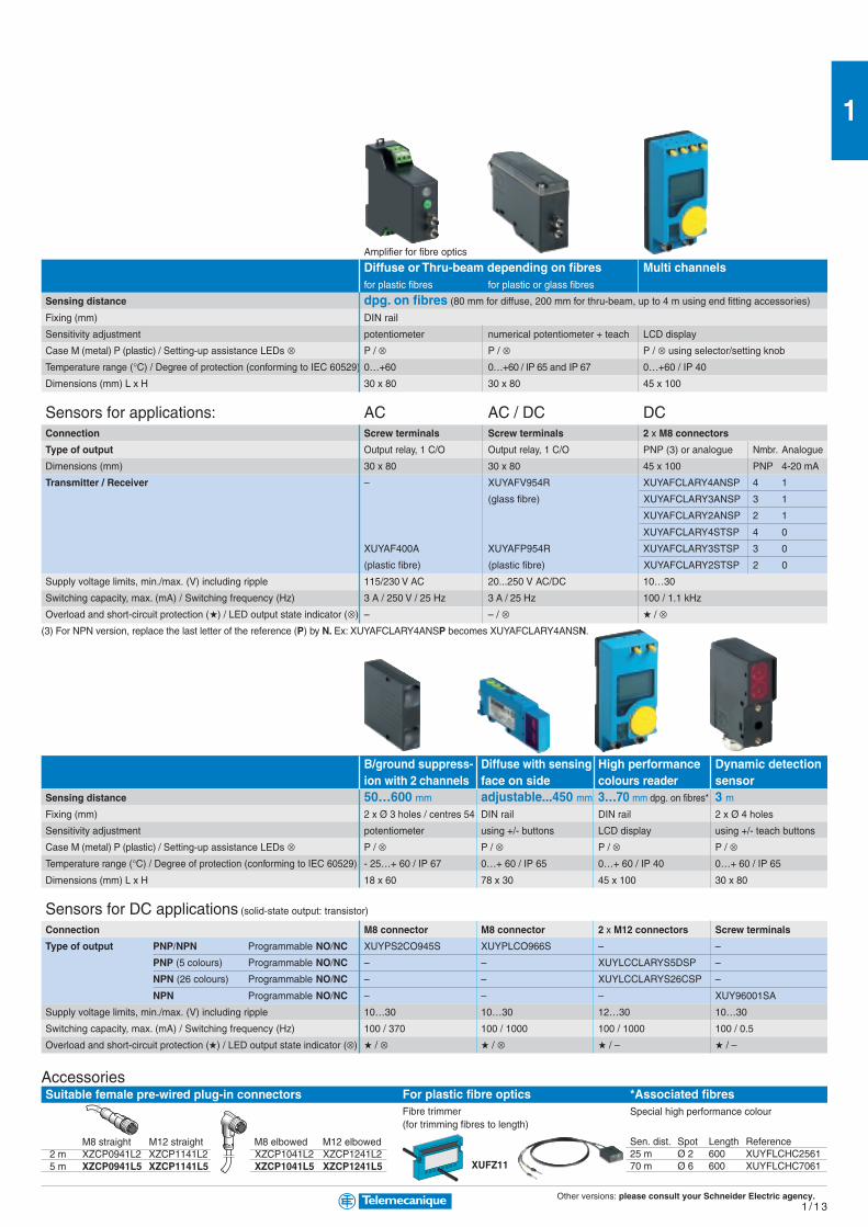
Amplifier for fibre optics
Diffuse or Thru-beam depending on fibres Multi channelsfor plastic fibres for plastic or glass fibres
Sensing distance dpg. on fibres (80 mm for diffuse, 200 mm for thru-beam, up to 4 m using end fitting accessories)
Fixing (mm) DIN rail
Sensitivity adjustment potentiometer numerical potentiometer + teach LCD display
Case M (metal) P (plastic) / Setting-up assistance LEDs ⊗ P / ⊗ P / ⊗ P / ⊗ using selector/setting knob
Temperature range (°C) / Degree of protection (conforming to IEC 60529) 0…+60 0…+60 / IP 65 and IP 67 0…+60 / IP 40
Dimensions (mm) L x H 30 x 80 30 x 80 45 x 100
Sensors for applications: AC AC / DC DCConnection Screw terminals Screw terminals 2 x M8 connectors
Type of output Output relay, 1 C/O Output relay, 1 C/O PNP (3) or analogue Nmbr. Analogue
Dimensions (mm) 30 x 80 30 x 80 45 x 100 PNP 4-20 mA
Transmitter / Receiver – XUYAFV954R XUYAFCLARY4ANSP 4 1
(glass fibre) XUYAFCLARY3ANSP 3 1
XUYAFCLARY2ANSP 2 1
XUYAFCLARY4STSP 4 0
XUYAF400A XUYAFP954R XUYAFCLARY3STSP 3 0
(plastic fibre) (plastic fibre) XUYAFCLARY2STSP 2 0
Supply voltage limits, min./max. (V) including ripple 115/230 V AC 20...250 V AC/DC 10…30
Switching capacity, max. (mA) / Switching frequency (Hz) 3 A / 250 V / 25 Hz 3 A / 25 Hz 100 / 1.1 kHz
Overload and short-circuit protection () / LED output state indicator (⊗) – – / ⊗ / ⊗(3) For NPN version, replace the last letter of the reference (P) by N. Ex: XUYAFCLARY4ANSP becomes XUYAFCLARY4ANSN.
B/ground suppress- Diffuse with sensing High performance Dynamic detectionion with 2 channels face on side colours reader sensor
Sensing distance 50…600 mm adjustable...450 mm 3…70 mm dpg. on fibres* 3 mFixing (mm) 2 x Ø 3 holes / centres 54 DIN rail DIN rail 2 x Ø 4 holes
Sensitivity adjustment potentiometer using +/- buttons LCD display using +/- teach buttons
Case M (metal) P (plastic) / Setting-up assistance LEDs ⊗ P / ⊗ P / ⊗ P / ⊗ P / ⊗Temperature range (°C) / Degree of protection (conforming to IEC 60529) - 25…+ 60 / IP 67 0…+ 60 / IP 65 0…+ 60 / IP 40 0…+ 60 / IP 65
Dimensions (mm) L x H 18 x 60 78 x 30 45 x 100 30 x 80
Sensors for DC applications (solid-state output: transistor)
Connection M8 connector M8 connector 2 x M12 connectors Screw terminals
Type of output PNP/NPN Programmable NO/NC XUYPS2CO945S XUYPLCO966S – –
PNP (5 colours) Programmable NO/NC – – XUYLCCLARYS5DSP –
NPN (26 colours) Programmable NO/NC – – XUYLCCLARYS26CSP –
NPN Programmable NO/NC – – – XUY96001SA
Supply voltage limits, min./max. (V) including ripple 10…30 10…30 12…30 10…30
Switching capacity, max. (mA) / Switching frequency (Hz) 100 / 370 100 / 1000 100 / 1000 100 / 0.5
Overload and short-circuit protection () / LED output state indicator (⊗) / ⊗ / ⊗ / – / –
AccessoriesSuitable female pre-wired plug-in connectors
M8 straight M12 straight M8 elbowed M12 elbowed2 m XZCP0941L2 XZCP1141L2 XZCP1041L2 XZCP1241L25 m XZCP0941L5 XZCP1141L5 XZCP1041L5 XZCP1241L5
For plastic fibre opticsFibre trimmer(for trimming fibres to length)
XUFZ11
*Associated fibresSpecial high performance colour
Sen. dist. Spot Length Reference25 m Ø 2 600 XUYFLCHC256170 m Ø 6 600 XUYFLCHC7061

Other versions: please consult your Schneider Electric agency.1 / 1 4
1
M8 M12 M18 M30
Nominal sensing distance Sn 2.5 mm 4 mm 8 mm 15 mm
Usable sensing distance S (mm) flush mountable / non flush mountable 0…2 0…3.2 0…6.4 0…12
Fine adjustment zone (mm) flush mountable / non flush mountable – – – –
Suitability for flush mounting (metal environment) flush mountable flush mountable flush mountable flush mountable
Case M (metal) P (plastic) M M M M
Temperature range (°C) - 25…+ 70 - 25…+ 70 - 25…+ 70 - 25…+ 70
Degree of protection (conforming to IEC 60529) IP 67 pre-cabled: IP 68 (with connector: IP 67)
Sensors for DC applicationsConnection Pre-cabled, PvR (2 m)
Dimensions (mm) Ø x L or W x H x D M8 x 50 M12 x 50 M18 x 60 M30 x 60
3-wire PNP NO function XS608B1PAL2 XS612B1PAL2 XS618B1PAL2 XS630B1PAL2
NC function XS608B1PBL2 XS612B1PBL2 XS618B1PBL2 XS630B1PBL2
NPN NO function XS608B1NAL2 XS612B1NAL2 XS618B1NAL2 XS630B1NAL2
NC function XS608B1NBL2 XS612B1NBL2 XS618B1NBL2 XS630B1NBL2
Connection M8 connector M12 connector
Dimensions (mm) Ø x L or W x H x D
3-wire PNP NO function XS608B1PAM12 XS612B1PAM12 XS618B1PAM12 XS630B1PAM12
NC function XS608B1PBM12 XS612B1PBM12 XS618B1PBM12 XS630B1PBM12
NPN NO function XS608B1NAM12 XS612B1NAM12 XS618B1NAM12 XS630B1NAM12
NC function XS608B1NBM12 XS612B1NBM12 XS618B1NBM12 XS630B1NBM12
Supply voltage limits, min./max. (V) including ripple 10…58 10…58 10…58 10…58
Switching capacity, max. (mA) 200 200 200 200
Overload and short-circuit protection ()
LED output state indicator (⊗) and power on LED (⊗) ⊗ / – ⊗ / – ⊗ / – ⊗ / –
Voltage drop, closed state (V) at I nominal ≤ 2 ≤ 2 ≤ 2 ≤ 2
Switching frequency (Hz) 2500 2500 1000 500
Multi-current/multi-voltage sensors for AC/DC applicationsConnection Pre-cabled, PvR (2 m)
Dimensions (mm) – M12 x 50 M18 x 60 M30 x 60
2-wire AC/DC NO function – XS612B1MAL2 XS618B1MAL2 XS630B1MAL2
not short-circuit protected (1) NC function – XS612B1MBL2 XS618B1MBL2 XS630B1MBL2
Connection 1/2"-20 UNF connector
Dimensions (mm) Ø x L or W x H x D
2-wire AC/DC NO function – XS612B1MAU20 XS618B1MAU20 XS630B1MAU20
not short-circuit protected (1) NC function – XS612B1MBU20 XS618B1MBU20 XS630B1MBU20
Supply voltage limits, min./max. (V) including ripple – 20…264 20…264 20…264
Switching capacity, max. (mA) – 200 300 AC / 200 DC 300 AC / 200 DC
LED output state indicator (⊗) / power on LED (⊗) – ⊗ / – ⊗ / – ⊗ / –
Residual current, open state (mA) – ≤ 1.5 ≤ 1.5 ≤ 1.5
Voltage drop, closed state (V) at I nominal – ≤ 5.5 ≤ 5.5 ≤ 5.5
Switching frequency (Hz) – 25 AC / 1000 DC 25 AC / 1000 DC 25 AC / 500 DC
(1) For these sensors without short-circuit protection, it is essential to connect a 0.4 A quick-blow fuse in series with the load.
Osiprox Inductive proximity sensorsUniversal
A single product that automaticallyadapts to all installation environ-ments.
Accurate position detection usingteach mode
Non flush mountable
Flush mountable
Snap-C® compatible
AccessoriesFixing
Fixing clamp with indexing pin forcylindrical sensors
M8 XSZB108M12 XSZB112M18 XSZB118M30 XSZB130
For flat sensors, forms E, C and Dsubstitutionof block type
flat 90° sensorsXSE / XSC / XSD
Form E XSZBE00 XSZBE90 XSZBE10Form C XSZBC00 XSZBC90 XSZBC10Form D – – XSZBD10flat
90°
Other versions: please consult your Schneider Electric agency.1 / 1 5
1
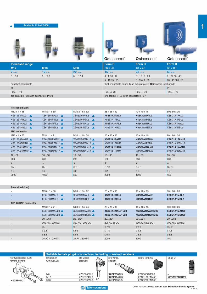
M8 XZCP0666L5 XZCP0566L5 XZCC8FCM30S –M12 XZCP1241L5 XZCP1141L5 XZCC12FCM40B XZCC12FDM40VU20 XZCP1965L5 XZCP1865L5 XZCC20FCM30B –
Suitable female plug-in connectors, including pre-wired versionslength 5 m pre-wired, pre-wired, screw terminal Snap-Cwithout LED elbowed straight
For Osiconcept XS6remote control
XSZBPM12
Increased range Form E Form C Form DM12 M18 M30 26 x 26 40 x 40 80 x 807 mm 12 mm 22 mm 15 mm 25 mm 60 mm
0 …5.6 0 … 9.6 0 … 17.6 0…8 / 0...12 0…12 / 0...20 0…32 / 0...48
5...10 / 5...15 8...15 / 8...25 20...40 / 20...60
non flush mountable flush mountable or non flush mountable via Osiconcept teach mode
M P P P
- 25…+ 70 - 25…+ 70 - 25…+ 70 - 25…+ 70
pre-cabled: IP 68 (with connector: IP 67) pre-cabled: IP 68 (with connector: IP 67)
Pre-cabled (2 m)
M12 x 1 x 55 M18 x 1 x 60 M30 x 1,5 x 62 26 x 26 x 13 40 x 40 x 15 80 x 80 x 26
XS612B4PAL2 XS618B4PAL2 XS630B4PAL2 XS8E1A1PAL2 XS8C1A1PAL2 XS8D1A1PAL2
XS612B4PBL2 XS618B4PBL2 XS630B4PBL2 XS8E1A1PBL2 XS8C1A1PBL2 XS8D1A1PBL2
XS612B4NAL2 XS618B4NAL2 XS630B4NAL2 XS8E1A1NAL2 XS8C1A1NAL2 XS8D1A1NAL2
XS612B4NBL2 XS618B4NBL2 XS630B4NBL2 XS8E1A1NBL2 XS8C1A1NBL2 XS8D1A1NBL2
M12 connector
M12 x 1 x 65 M18 x 1 x 71 M30 x 1.5 x 74 26 x 26 x 13 40 x 40 x 15 80 x 80 x 26
XS612B4PAM12 XS618B4PAM12 XS630B4PAM12 XS8E1A1PAM8 XS8C1A1PAM8 XS8D1A1PAM12
XS612B4PBM12 XS618B4PBM12 XS630B4PBM12 XS8E1A1PBM8 XS8C1A1PBM8 XS8D1A1PBM12
XS612B4NAM12 XS618B4NAM12 XS630B4NAM12 XS8E1A1NAM8 XS8C1A1NAM8 XS8D1A1NAM12
XS612B4NBM12 XS618B4NBM12 XS630B4NBM12 XS8E1A1NBM8 XS8C1A1NBM8 XS8D1A1NBM12
10…58 10…58 10…58 10…36 10…36 10…36
200 200 200 100 200 200
⊗ / – ⊗ / – ⊗ / – ⊗ / ⊗ ⊗ / ⊗ ⊗ / ⊗≤ 2 ≤ 2 ≤ 2 ≤ 2 ≤ 2 ≤ 2
2500 1000 500 2000 1000 150
Pre-cabled (2 m)
– M18 x 1 x 60 M30 x 1.5 x 62 26 x 26 x 13 40 x 40 x 15 80 x 80 x 26
– XS618B4MAL2 XS630B4MAL2 XS8E1A1MAL2 XS8C1A1MAL2 XS8D1A1MAL2
– XS618B4MBL2 XS630B4MBL2 XS8E1A1MBL2 XS8C1A1MBL2 XS8D1A1MBL2
1/2"-20 UNF connector
– M18 x 1 x 71 M30 x 1.5 x 74 26 x 26 x 13 40 x 40 x 15 80 x 80 x 26
– XS618B4MAU20 XS630B4MAU20 XS8E1A1MAL01U20 XS8C1A1MAL01U20 XS8D1A1MAU20
– XS618B4MBU20 XS630B4MBU20 XS8E1A1MBL01U20 XS8C1A1MBL01U20 XS8D1A1MBU20
– 20…264 20…264 20…264 20…264 20…264
– 300 AC / 200 DC 300 AC / 200 DC 200 AC or DC 300 AC / 200 DC 300 AC / 200 DC
– ⊗ / – ⊗ / – ⊗ / ⊗ ⊗ / ⊗ ⊗ / ⊗– ≤ 0.8 ≤ 0.8 ≤ 1.5 ≤ 1.5 ≤ 1.5
– ≤ 5.5 ≤ 5.5 ≤ 5.5 ≤ 5.5 ≤ 5.5
– 25 AC / 1000 DC 25 AC / 300 DC 2000 1000 150
Available 1st half 2006

Other versions: please consult your Schneider Electric agency.1 / 1 6
1
Osiprox Inductive proximity sensorsOptimum
Flush mountable
AccessoriesFixing
Fixing clamp with indexing pinfor cylindrical sensors
M8 XSZB108M12 XSZB112M18 XSZB118M30 XSZB130
For flat sensors, forms E, C and Dsubstitutionof block type
flat 90° sensorsXSE / XSC / XSD
Form E XSZBE00 XSZBE90 XSZBE10Form C XSZBC00 XSZBC90 XSZBC10Form D – – XSZBD10flat
90°
Form J Form F Form E Form C Form D8 x 22 15 x 32 26 x 26 40 x 40 80 x 80
Nominal sensing distance Sn 2.5 mm 5 mm 10 mm 15 mm 40 mm
Operating zone (mm) 0...2 0...4 0…8 0…12 0…32
Suitability for flush mounting (metal environment) flush mountable flush mountable flush mountable flush mountable flush mountable
Case M (metal) P (plastic) P P P P P
Temperature range (°C) - 25…+ 70 - 25…+ 70 - 25…+ 70 - 25…+ 70 - 25…+ 70
Degree of protection (conforming to IEC 60529) pre-cabled: IP 68 (with connector: IP 67)
Sensors for DC applicationsConnection Pre-cabled, PvR (2 m)
Dimensions (mm) Ø x L or W x H x D 8 x 22 x 8 15 x 32 x 8 26 x 26 x 13 40 x 40 x 15 80 x 80 x 26
3-wire PNP NO function XS7J1A1PAL2 XS7F1A1PAL2 XS7E1A1PAL2 XS7C1A1PAL2 XS7D1A1PAL2
NC function XS7J1A1PBL2 XS7F1A1PBL2 XS7E1A1PBL2 XS7C1A1PBL2 XS7D1A1PBL2
NPN NO function XS7J1A1NAL2 XS7F1A1NAL2 XS7E1A1NAL2 XS7C1A1NAL2 XS7D1A1NAL2
NC function XS7J1A1NBL2 XS7F1A1NBL2 XS7E1A1NBL2 XS7C1A1NBL2 XS7D1A1NBL2
Connection M8 connector M12 connector
3-wire PNP NO function XS7J1A1PAL01M8 (1) XS7F1A1PAL01M8 (1) XS7E1A1PAM8 XS7C1A1PAM8 XS7D1A1PAM12
NC function XS7J1A1PBL01M8 (1) XS7F1A1PBL01M8 (1) XS7E1A1PBM8 XS7C1A1PBM8 XS7D1A1PBM12
NPN NO function XS7J1A1NAL01M8 (1) XS7F1A1NAL01M8 (1) XS7E1A1NAM8 XS7C1A1NAM8 XS7D1A1NAM12
NC function XS7J1A1NBL01M8 (1) XS7F1A1NBL01M8 (1) XS7E1A1NBM8 XS7C1A1NBM8 XS7D1A1NBM12
Supply voltage limits, min./max. (V) including ripple 10…36 10…36 10…36 10…36 10…36
Switching capacity, max. (mA) 100 100 100 100 100
Overload and short-circuit protection () / LED output state indicator (⊗) / ⊗ / ⊗ / ⊗ / ⊗ / ⊗Voltage drop, closed state (V) at I nominal ≤ 2 ≤ 2 ≤ 2 ≤ 2 ≤ 2
Switching frequency (Hz) 2000 2000 1000 1000 100
Sensors for DC applicationsConnection Pre-cabled, PvR (2 m)
Dimensions (mm) Ø x L or W x H x D 8 x 22 x 8 15 x 32 x 8 26 x 26 x 13 40 x 40 x 15 80 x 80 x 26
2-wire non NO function XS7J1A1DAL2 XS7F1A1DAL2 XS7E1A1DAL2 XS7C1A1DAL2 XS7D1A1DAL2polarised
NC function XS7J1A1DBL2 XS7F1A1DBL2 XS7E1A1DBL2 XS7C1A1DBL2 XS7D1A1DBL2
Connection M8 connector M12 connector
2-wire non NO function XS7J1A1DAL01M8 (1) XS7F1A1DAL01M8 (1) XS7E1A1DAM8 XS7C1A1DAM8 XS7D1A1DAM12polarised
NC function XS7J1A1DBL01M8 (1) XS7F1A1DBL01M8 (1) XS7E1A1DBM8 XS7C1A1DBM8 XS7D1A1DBM12
Supply voltage limits, min./max. (V) including ripple 10…36 10…36 10…36 10…36 10…36
Switching capacity, max. (mA) 100 100 100 100 100
Overload and short-circuit protection () / LED output state indicator (⊗) / ⊗ / ⊗ / ⊗ / ⊗ / ⊗Residual current, open state (mA) ≤ 0.5 ≤ 0.5 ≤ 0.5 ≤ 0.5 ≤ 0.5
Voltage drop, closed state (V) at I nominal ≤ 4 ≤ 4 ≤ 4 ≤ 4 ≤ 4
Switching frequency (Hz) 4000 5000 1000 1000 100
(1) M8 connector on flying lead (L = 0.15 m).
Snap-C® compatibl
Snap-C® compatibl

Other versions: please consult your Schneider Electric agency.1 / 1 7
1
M8 (or S) XZCP0666L5 XZCP0566L5 XZCC8FCM30S –M12 (or D) XZCP1241L5 XZCP1141L5 XZCC12FCM40B XZCC12FDM40VU20 (or K) XZCP1965L5 XZCP1865L5 XZCC20FCM30B –
Suitable female plug-in connectors, including pre-wired versionslength 5 m pre-wired, pre-wired, screw terminal Snap-Cwithout LED elbowed straight
Snap-C® compatibleSnap-C®
compatible
Increased range Standard rangeM8 M12 M18 M30 M8 M12 M 18 M 302.5 mm 4 mm 10 mm 20 mm 1.5 mm 2 mm 5 mm 10 mm
0…2 0…3.2 0…8 0…16 0…1.2 0…1.6 0…4 0…8
flush mountable non flush mountable flush mountable non flush mountable flush mountable flush mountable flush mountable flush mountable
M M M M M M M M
- 25…+ 50 - 25…+ 50 - 25…+ 50 - 25…+ 50 - 25…+ 70 - 25…+ 70 - 25…+ 70 - 25…+ 70
IP 67 IP 68 (with connector: IP 67) IP 67 pre-cabled: IP 68 (with connector: IP 67)
Short case Short case
Pre-cabled, PvR (2 m) Pre-cabled, PvR (2 m)
M8 x 33 M12 x 33 M18 x 36.5 M30 x 40.6 M8 x 33 M12 x 33 M18 x 36.5 M30 x 40.6
XS1N08PA349 XS1N12PA349 XS1N18PA349 XS1N30PA349 XS508B1PAL2 XS512B1PAL2 XS518B1PAL2 XS530B1PAL2
XS1N08PB349 XS1N12PB349 XS1N18PB349 XS1N30PB349 XS508B1PBL2 XS512B1PBL2 XS518B1PBL2 XS530B1PBL2
XS1N08NA349 XS1N12NA349 XS1N18NA349 XS1N30NA349 XS508B1NAL2 XS512B1NAL2 XS518B1NAL2 XS530B1NAL2
XS1N08NB349 XS1N12NB349 XS1N18NB349 XS1N30NB349 XS508B1NBL2 XS512B1NBL2 XS518B1NBL2 XS530B1NBL2
M8 connector M12 connector M8 connector M12 connector
XS1N08PA349S XS1N12PA349D XS1N18PA349D XS1N30PA349D XS508B1PAM8 XS512B1PAM12 XS518B1PAM12 XS530B1PAM12
XS1N08PB349S XS1N12PB349D XS1N18PB349D XS1N30PB349D XS508B1PBM8 XS512B1PBM12 XS518B1PBM12 XS530B1PBM12
XS1N08NA349S XS1N12NA349D XS1N18NA349D XS1N30NA349D XS508B1NAM8 XS512B1NAM12 XS518B1NAM12 XS530B1NAM12
XS1N08NB349S XS1N12NB349D XS1N18NB349D XS1N30NB349D XS508B1NBM8 XS512B1NBM12 XS518B1NBM12 XS530B1NBM12
10…36 10…36 10…36 10…36 10…36 10…36 10…36 10…36
200 200 200 200 200 200 200 200
/ – / – / – / – / ⊗ / ⊗ / ⊗ / ⊗≤ 2 ≤ 2 ≤ 2 ≤ 2 ≤ 2 ≤ 2 ≤ 2 ≤ 2
2500 2500 1000 500 5000 5000 2000 1000
Long case
Pre-cabled, PvR (2 m)
– – – – M8 x 50 M12 x 50 M18 x 52.5 M30 x 50
– – – – XS508B1DAL2 XS512B1DAL2 XS518B1DAL2 XS530B1DAL2
– – – – XS508B1DBL2 XS512B1DBL2 XS518B1DBL2 XS530B1DBL2
M12 connector
– – – – XS508B1DAM12 XS512B1DAM12 XS518B1DAM12 XS530B1DAM12
– – – – XS508B1DBM12 XS512B1DBM12 XS518B1DBM12 XS530B1DBM12
– – – – 10…58 10…58 10…58 10…58
– – – – 100 100 100 100
– – – – / ⊗ / ⊗ / ⊗ / ⊗– – – – ≤ 0.5 ≤ 0.5 ≤ 0.5 ≤ 0.5
– – – – ≤ 4 ≤ 4 ≤ 4 ≤ 4
– – – – 4000 4000 3000 2000
Snap-C® compatible
le
le

Other versions: please consult your Schneider Electric agency.1 / 1 8
1
Osiprox Inductive proximity sensors - ApplicationPlastic cylindrical
Non flushmountable
Flushmountable
M8 M12 M18 M30
Nominal sensing distance Sn 2.5 mm 4 mm 8 mm 15 mm
Operating zone (mm) 0…2 0…3.2 0…6.4 0…12
Suitability for flush mounting (metal environment) non flush mountable
Case M (metal) P (plastic) P
Temperature range (°C) - 25…+ 70
Degree of protection (conforming to IEC 60529) IP 67 pre-cabled: IP 68 (with connector: IP 67)
Sensors for DC applicationsConnection Pre-cabled, PvR (2 m)
Dimensions (mm) Ø x L or W x H x D M8 x 33 M12 x 33 M18 x 33.5 M30 x 40.5
2-wire (non polarised) NO or NC programmable – – – –
4-wire PNP NO + NC complementary outputs – – – –
NPN NO + NC complementary outputs – – – –
3-wire PNP NO function XS4P08PA340 XS4P12PA340 XS4P18PA340 XS4P30PA340
NC function XS4P08PB340 XS4P12PB340 XS4P18PB340 XS4P30PB340
NPN NO function XS4P08NA340 XS4P12NA340 XS4P18NA340 XS4P30NA340
NC function XS4P08NB340 XS4P12NB340 XS4P18NB340 XS4P30NB340
Connection M8 connector M12 connector
3-wire PNP NO function XS4P08PA340S XS4P12PA340D XS4P18PA340D XS4P30PA340D
NC function XS4P08PB340S XS4P12PB340D XS4P18PB340D XS4P30PB340D
NPN NO function XS4P08NA340S XS4P12NA340D XS4P18NA340D XS4P30NA340D
NC function XS4P08NB340S XS4P12NB340D XS4P18NB340D XS4P30NB340D
Supply voltage limits, min./max. (V) including ripple 10…38 10…38 10…38 10…38
Switching capacity, max. (mA) 200 200 200 200
Short-circuit protect. () / LED output state indicator (⊗) / Power on LED (⊗) / ⊗ / – / ⊗ / – / ⊗ / – / ⊗ / –
Voltage drop, closed state (V) at I nominal ≤ 2 ≤ 2 ≤ 2 ≤ 2
Switching frequency (Hz) 5000 5000 2000 1000
Multi-current/multi-voltage sensors for AC/DC applicationsConnection Pre-cabled, PvR (2 m)
Dimensions (mm) Ø x L or W x D x H M8 x 50 M12 x 50 M18 x 60 M30 x 60
2-wire AC/DC NO function XS4P08MA230 XS4P12MA230 XS4P18MA230 XS4P30MA230
not short-circuit protected (1) NC function XS4P08MB230 XS4P12MB230 XS4P18MB230 XS4P30MB230
AC NO or NC programmable – – – –
AC/DC NO or NC programmable – – – –
Connection U20 connector
2-wire AC/DC NO function XS4P08MA230K XS4P12MA230K XS4P18MA230K XS4P30MA230K
not short-circuit protected (1) NC function XS4P08MB230K XS4P12MB230K XS4P18MB230K XS4P30MB230K
Supply voltage limits, min./max. (V) including ripple 20…264 20…264 20…264 20…264
Switching capacity, max. (mA) 100 200 300 AC / 200 DC 300 AC / 200 DC
LED output state indicator (⊗) ⊗ ⊗ ⊗ ⊗Residual current, open state (mA) ≤ 0.6 ≤ 0.6 ≤ 0.6 ≤ 0.6
Voltage drop, closed state (V) at I nominal ≤ 5.5 ≤ 5.5 ≤ 5.5 ≤ 5.5
Switching frequency (Hz) 25 AC / 3000 DC 25 AC / 3000 DC 25 AC / 2000 DC 25 AC / 1000 DC
(1) For these sensors without short-circuit protection, it is essential to connect a 0.4 A quick-blow fuse in series with the load.
AccessoriesFixing clampsFixing clamp with indexing pinfor cylindrical sensors
M4 XSZB104
M5 XSZB105
M6.5 XSZB165
M8 XSZB108
M12 XSZB112
M18 XSZB118
M30 XSZB130

Other versions: please consult your Schneider Electric agency.1 / 1 9
1
Ø 4 M5 Ø 6.5 Form C
1 mm 1 mm 1.5 mm 15 mm 20 mm increased range 20 mm 40 mm increased range
0...0.8 0...0.8 0...1.2 0…12 0…16 0…16 0…32
flush mountable flush mountable non flush mountable
M P
- 25…+ 70 - 25…+ 70
IP 67 IP 67
Pre-cabled, PvR (2 m) Screw terminals (3)
Ø 4 x 29 M5 x 29 M6.5 x 33 40 x 40 x 117
– – – XS7C40DP210 – XS8C40DP210 –
– – – XS7C40PC440 XS7C40PC449 XS8C40PC440 XS8C40PC449
– – – XS7C40NC440 XS7C40NC449 XS8C40NC440 XS8C40NC449
XS1L04PA310 XS1N05PA310 XS1L06PA340 – – – –
– – – – – – –
XS1L04NA310 XS1N05NA310 XS1L06NA340 – – – –
– – – – – – –
M8 connector
XS1L04PA310S XS1N05PA311S (2) XS1L06PA340S – – – –
– – – – – – –
XS1L04NA310S XS1N05NA311S (2) XS1L06NA340S – – – –
– – – – – – –
5...30 5...30 10...38 12…48
100 100 200 4-wire version = 200 – 2-wire version = 1.5…100
/ ⊗ / – / ⊗ / – / ⊗ / – 4-wire version = / ⊗ / ⊗ – 2-wire version = / ⊗ / –
≤ 2 ≤ 2 ≤ 2 4-wire version = ≤ 2 – 2-wire version = ≤ 4
5000 5000 2500 2-wire = 1500 / 4-wire = 1000 2-wire = 800 / 4-wire = 1000 (20mm) 500 (40mm)
Screw terminals (3)
– – – 40 x 40 x 117
– – – – – – –
– – – – – – –
– – – XS7C40FP260 – XS8C40FP260 –
– – – XS7C40MP230 – XS8C40MP230 –
– – – – – – –
– – – – – – –
– – – 20…264
– – – AC version = 500 – AC/DC version = 300 / 200
– – – ⊗– – – AC version = ≤ 1.5 – AC/DC version = ≤ 0.8 / 1.5
– – – ≤ 5.5
– – – 25 AC / 50 DC
(2) Stainless steel sensors, Sn = 0.8 mm.
(3) Sensors supplied without cable gland. Suitable cable gland: 13P.
Miniature cylindrical (assembly) Rectangular Form C
Suitable female plug-in connectors, including pre-wired versions
length 5 m pre-wired,without LED elbowed
M8 (or S) XZCP0666L5M12 (or D) XZCP1241L5U20 (or K) XZCP1965L5
pre-wired,straight
XZCP0566L5XZCP1141L5XZCP1865L5
screw terminal
XZCC8FCM30SXZCC12FCM40BXZCC20FCM30B

Other versions: please consult your Schneider Electric agency.1 / 2 0
1
Osiprox Inductive proximity sensors - TechnologyMulti-voltage with short-circuit protection
M12 M18 M30
Sensing distance Sn flush mountable 2 mm 5 mm 10 mm
non flush mountable 4 mm 8 mm 15 mm
Operating zone (mm) non flush mountable 0…1.6 0…4 0…8
flush mountable 0…3.2 0…6.4 0…12
Suitability for flush mounting (metal environment) flush mountable or non flush mountable depending on model
Case M (metal) P (plastic) M
Temperature range (°C) - 25…+ 70
Degree of protection (conforming to IEC 60529) IP 68 (with connector: IP 67)
Dimensions (mm) Ø x L M12 x 55 M18 x 60 M30 x 60
Sensors for DC applicationsConnection
4-wire PNP NO + NC flush mountable – – –
non flush mountable – – –
NPN NO + NC flush mountable – – –
non flush mountable – – –
PNP+NPN NO/NC flush mountable (metal) – – –
programmable non flush mntbl. (metal) – – –
non flush mntbl. (plastic) – – –
Connection
4-wire PNP NO + NC flush mountable – – –
non flush mountable – – –
NPN NO + NC flush mountable – – –
non flush mountable – – –
PNP+NPN NO/NC flush mountable (metal) – – –
programmable non flush mntbl. (metal) – – –
non flush mntbl. (plastic) – – –
Supply voltage limits, min./max. (V) including ripple – – –
Switching capacity, max. (mA) – – –
Short-circuit protection () / LED output state indicator (⊗) – – –
Voltage drop, closed state (V) at I nominal – – –
Switching frequency (Hz) – – –
Multi-current/multi-voltage sensors for AC/DC applicationsConnection Pre-cabled, PvR (2 m)
2-wire AC/DC NO function flush mountable XS1M12MA250 XS1M18MA250 XS1M30MA250
non flush mountable XS2M12MA250 XS2M18MA250 XS2M30MA250
NC function flush mountable XS1M12MB250 XS1M18MB250 XS1M30MB250
non flush mountable XS2M12MB250 XS2M18MB250 XS2M30MB250
Connection 1/2"-20 UNF connector
2-wire AC/DC NO function flush mountable XS1M12MA250K XS1M18MA250K XS1M30MA250K
non flush mountable XS2M12MA250K XS2M18MA250K XS2M30MA250K
NC function flush mountable XS1M12MB250K XS1M18MB250K XS1M30MB250K
non flush mountable XS2M12MB250K XS2M18MB250K XS2M30MB250K
Supply voltage limits, min./max. (V) 50-60 Hz 20…264
Switching capacity, max. (mA) 5…200 5…200 AC, 5…300 DC
LED output state indicator (⊗) / Power on LED (⊗) ⊗ / ⊗Residual current, open state (mA) ≤ 1.5
Voltage drop, closed state (V) at I nominal ≤ 5.5
Switching frequency (Hz) 25 AC, 4000 DC 25 AC, 2000 DC 25 AC, 2000 DC (1)
(1) 25 AC, 1000 DC for non flush mountable Ø 30 mm.
Non flushmountable
Flushmountable
Other versions: please consult your Schneider Electric agency.1 / 2 1
1
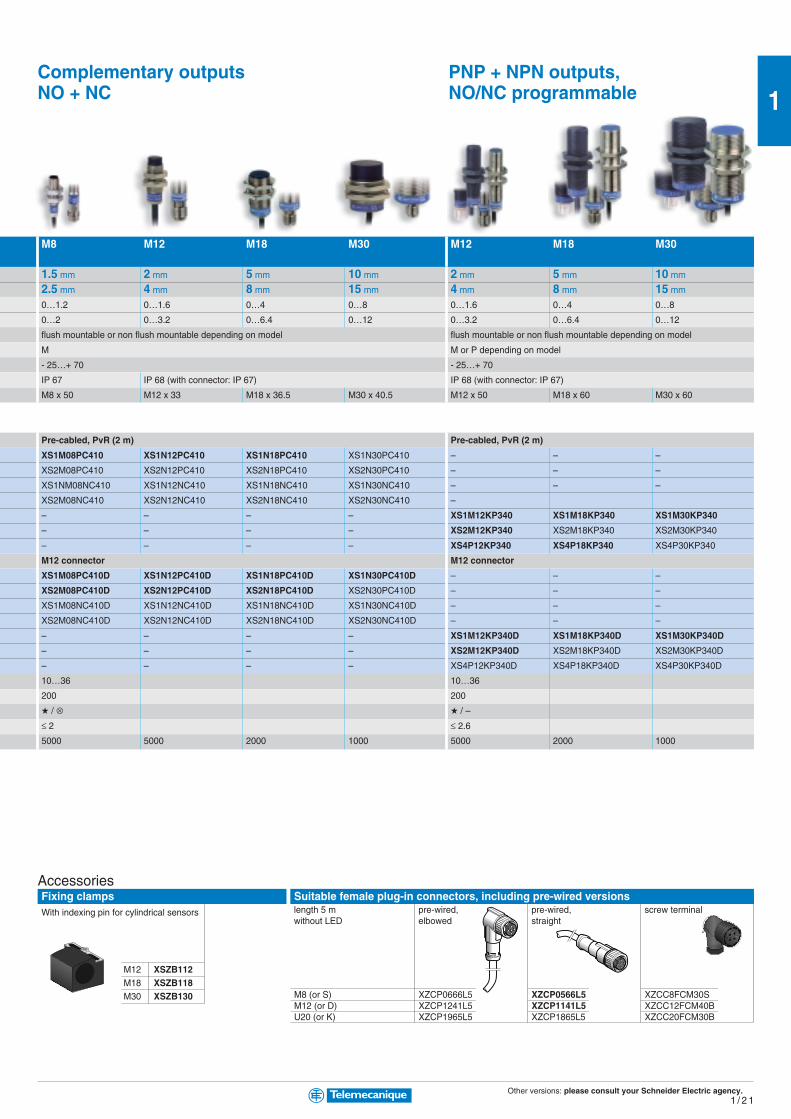
M8 (or S) XZCP0666L5 XZCP0566L5 XZCC8FCM30SM12 (or D) XZCP1241L5 XZCP1141L5 XZCC12FCM40BU20 (or K) XZCP1965L5 XZCP1865L5 XZCC20FCM30B
Complementary outputsNO + NC
PNP + NPN outputs,NO/NC programmable
M8 M12 M18 M30 M12 M18 M30
1.5 mm 2 mm 5 mm 10 mm 2 mm 5 mm 10 mm
2.5 mm 4 mm 8 mm 15 mm 4 mm 8 mm 15 mm
0…1.2 0…1.6 0…4 0…8 0…1.6 0…4 0…8
0…2 0…3.2 0…6.4 0…12 0…3.2 0…6.4 0…12
flush mountable or non flush mountable depending on model flush mountable or non flush mountable depending on model
M M or P depending on model
- 25…+ 70 - 25…+ 70
IP 67 IP 68 (with connector: IP 67) IP 68 (with connector: IP 67)
M8 x 50 M12 x 33 M18 x 36.5 M30 x 40.5 M12 x 50 M18 x 60 M30 x 60
Pre-cabled, PvR (2 m) Pre-cabled, PvR (2 m)
XS1M08PC410 XS1N12PC410 XS1N18PC410 XS1N30PC410 – – –
XS2M08PC410 XS2N12PC410 XS2N18PC410 XS2N30PC410 – – –
XS1NM08NC410 XS1N12NC410 XS1N18NC410 XS1N30NC410 – – –
XS2M08NC410 XS2N12NC410 XS2N18NC410 XS2N30NC410 –
– – – – XS1M12KP340 XS1M18KP340 XS1M30KP340
– – – – XS2M12KP340 XS2M18KP340 XS2M30KP340
– – – – XS4P12KP340 XS4P18KP340 XS4P30KP340
M12 connector M12 connector
XS1M08PC410D XS1N12PC410D XS1N18PC410D XS1N30PC410D – – –
XS2M08PC410D XS2N12PC410D XS2N18PC410D XS2N30PC410D – – –
XS1M08NC410D XS1N12NC410D XS1N18NC410D XS1N30NC410D – – –
XS2M08NC410D XS2N12NC410D XS2N18NC410D XS2N30NC410D – – –
– – – – XS1M12KP340D XS1M18KP340D XS1M30KP340D
– – – – XS2M12KP340D XS2M18KP340D XS2M30KP340D
– – – – XS4P12KP340D XS4P18KP340D XS4P30KP340D
10…36 10…36
200 200
/ ⊗ / –
≤ 2 ≤ 2.6
5000 5000 2000 1000 5000 2000 1000
M12 XSZB112M18 XSZB118M30 XSZB130
With indexing pin for cylindrical sensors
AccessoriesFixing clamps Suitable female plug-in connectors, including pre-wired versions
length 5 m pre-wired, pre-wired, screw terminalwithout LED elbowed straight
Other versions: please consult your Schneider Electric agency.1 / 2 2
1
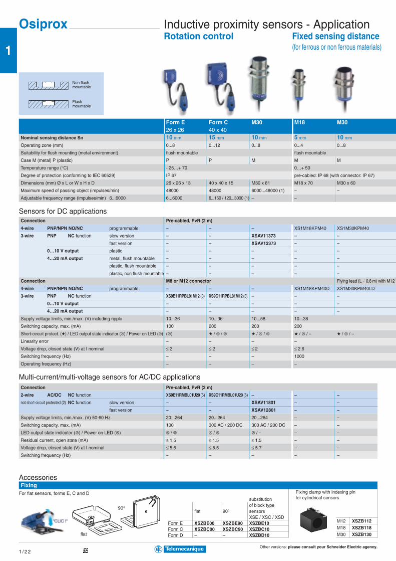
Form E Form C M30 M18 M3026 x 26 40 x 40
Nominal sensing distance Sn 10 mm 15 mm 10 mm 5 mm 10 mm
Operating zone (mm) 0...8 0...12 0...8 0...4 0...8
Suitability for flush mounting (metal environment) flush mountable flush mountable
Case M (metal) P (plastic) P P M M M
Temperature range (°C) - 25…+ 70 0…+ 50
Degree of protection (conforming to IEC 60529) IP 67 pre-cabled: IP 68 (with connector: IP 67)
Dimensions (mm) Ø x L or W x H x D 26 x 26 x 13 40 x 40 x 15 M30 x 81 M18 x 70 M30 x 60
Maximum speed of passing object (impulses/min) 48000 48000 6000...48000 (1) – –
Adjustable frequency range (impulses/min) 6...6000 6...6000 6...150 / 120...3000 (1) – –
Sensors for DC applicationsConnection Pre-cabled, PvR (2 m)
4-wire PNP/NPN NO/NC programmable – – – XS1M18KPM40 XS1M30KPM40
3-wire PNP NC function slow version – – XSAV11373 – –
fast version – – XSAV12373 – –
0…10 V output plastic – – – – –
4…20 mA output metal, flush mountable – – – – –
plastic, flush mountable – – – – –
plastic, non flush mountable – – – – –
Connection M8 or M12 connector Flying lead (L = 0.8 m) with M12 c
4-wire PNP/NPN NO/NC programmable – – – XS1M18KPM40D XS1M30KPM40LD
3-wire PNP NC function XS9E11RPBL01M12 (3) XS9C11RPBL01M12 (3) – – –
0…10 V output – – – – –
4…20 mA output – – – – –
Supply voltage limits, min./max. (V) including ripple 10...36 10...36 10...58 10...38
Switching capacity, max. (mA) 100 200 200 200
Short-circuit protect. () / LED output state indicator (⊗) / Power on LED (⊗) (⊗) / ⊗ / ⊗ / ⊗ / ⊗ / ⊗ / – / ⊗ / –Linearity error – – – –
Voltage drop, closed state (V) at I nominal ≤ 2 ≤ 2 ≤ 2 ≤ 2.6
Switching frequency (Hz) – – – 1000
Operating frequency (Hz) – – – –
Multi-current/multi-voltage sensors for AC/DC applicationsConnection Pre-cabled, PvR (2 m)
2-wire AC/DC NC function XS9E11RMBL01U20 (5) XS9C11RMBL01U20 (5) – – –
not short-circuit protected (2) NC function slow version – – XSAV11801 – –
fast version – – XSAV12801 – –
Supply voltage limits, min./max. (V) 50-60 Hz 20...264 20...264 20...264 – –
Switching capacity, max. (mA) 100 300 AC / 200 DC 300 AC / 200 DC – –
LED output state indicator (⊗) / Power on LED (⊗) ⊗ / ⊗ ⊗ / ⊗ ⊗ / – – –
Residual current, open state (mA) ≤ 1.5 ≤ 1.5 ≤ 1.5 – –
Voltage drop, closed state (V) at I nominal ≤ 5.5 ≤ 5.5 ≤ 5.7 – –
Switching frequency (Hz) – – – – –
Inductive proximity sensors - ApplicationRotation control
Non flushmountable
Flushmountable
Fixed sensing distance(for ferrous or non ferrous materials)
Osiprox
AccessoriesFixing
Fixing clamp with indexing pinfor cylindrical sensors
M12 XSZB112M18 XSZB118M30 XSZB130
For flat sensors, forms E, C and Dsubstitutionof block type
flat 90° sensorsXSE / XSC / XSD
Form E XSZBE00 XSZBE90 XSZBE10Form C XSZBC00 XSZBC90 XSZBC10Form D – – XSZBD10flat
90°

Other versions: please consult your Schneider Electric agency.1 / 2 3
1
M8 XZCP0666L5 XZCP0566L5 XZCC8FCM30SM12 (or D) XZCP1241L5 XZCP1141L5 XZCC12FCM40BU20 XZCP1965L5 XZCP1865L5 XZCC20FCM30B
connector
Form F Form E Form C Form D M12 M18 M308 x 32 26 x 26 40 x 40 80 x 805 mm 10 mm 15 mm 40 mm M: 2 mm / P: 4 mm M: 5 mm / P: 8 mm M: 10 mm / P: 15 mm
1...4 1...10 2...15 5...40 M: 0.2…2 / P: 0.4…4 M: 0.5…5 / P: 0.8…8 M: 1…10 / P: 1.5…15
flush mountable flush mountable flush mountable flush mountable flush / non flush mountable flush / non flush mountable flush / non flush mountable
P P P P M or P M or P M or P
- 25…+ 70 - 25…+ 70 - 25…+ 70 - 25…+ 70 - 25…+ 70 - 25…+ 70 - 25…+ 70
pre-cabled: IP 68 (with connector: IP 67) IP 67
15 x 32 x 8 26 x 26 x 13 40 x 40 x 15 80 x 80 x 26 Ø 12 x 50 Ø 18 x 50 Ø 30 x 52.5
– – – – – – –
– – – – – – –
– – – – – – –
– – – – – – –
– – – – – – –
XS9F111A1L2 XS9E111A1L2 XS9C111A1L2 XS9D111A1L2 XS4P12AB110 XS4P18AB110 XS4P30AB110
– – – – XS1M12AB120 XS1M18AB120 XS1M30AB120
XS9F111A2L2 XS9E111A2L2 XS9C111A2L2 XS9D111A2L2 – – –
– – – – XS4P12AB120 XS4P18AB120 XS4P30AB120
M8 or M12 connector
– – – – – – –
– – – – – – –
XS9F111A1L01M8 (4) XS9E111A1L01M12 (4) XS9C111A1L01M12 (4) XS9D111A1M12 – – –
XS9F111A2L01M8 (4) XS9E111A2L01M12 (4) XS9C111A2L01M12 (4) XS9D111A2M12 – – –
10...36 10...36 10...36 10...36 10…38 10…38 10…38
– – – – – – –
– – – – – – –
± 1 V for 0…10 V version / ± 2 mA for 4…20 mA version
– – – – – – –
– – – – – – –
2000 1000 1000 100 1500 500 300
(1) 6...150 and 6000 impulses/min for XSAV11373 and XSAV11801 (slow version); 120...3000 and 48000 impulses/min for XSAV12373 and XSAV12801 (fast version).
(2) For these sensors without short-circuit protection, it is essential to connect a 0.4 A quick-blow fuse in series with the load.
(3) Flying lead (L = 0.15 m) with end mounted remote control incorporating M12 connector.
(4) Flying lead (L = 0.15 m) with end connector.
(5) Flying lead (L = 0.15 m) with end mounted remote control incorporating 1/2"-20 UNF connector.
Analogue (Position control)
Suitable female plug-in connectors, including pre-wired versionslength 5 m pre-wired, pre-wired, screw terminalwithout LED elbowed straight
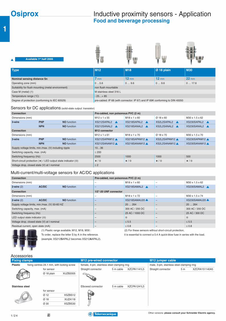
Other versions: please consult your Schneider Electric agency.1 / 2 4
1
Inductive proximity sensors - ApplicationFood and beverage processing
Osiprox
AccessoriesFixing clampsPlastic fixing centres 24.1 mm, with locking screw
for sensor
Ø 18 plain XUZB2005
Stainless steel
for sensor
Ø 12 XSZBS12
Ø 18 XUZA118
Ø 30 XSZBS30
Type M12 M18 Ø 18 plain M30
Nominal sensing distance Sn 7 mm 12 mm 12 mm 22 mm
Operating zone (mm) 0 …5.6 0 … 9.6 0 … 9.6 0 … 17.6
Suitability for flush mounting (metal environment) non flush mountable
Case M (metal) (1) M stainless steel 316 L
Temperature range (°C) - 25…+ 85
Degree of protection (conforming to IEC 60529) pre-cabled: IP 68 (with connector: IP 67) and IP 69K conforming to DIN 40050
Sensors for DC applications (solid-state output: transistor)
Connection Pre-cabled, non poisonous PVC (2 m)
Dimensions (mm) M12 x 1 x 55 M18 x 1 x 60 Ø 18 x 60 M30 x 1.5 x 62
3-wire PNP NO function XS212SAPAL2 XS218SAPAL2 XS2L2SAPAL2 XS230SAPAL2
NPN NO function XS212SANAL2 XS218SANAL2 XS2L2SANAL2 XS230SANAL2
Connection M12 connector
Dimensions (mm) M12 x 1 x 61 M18 x 1 x 70 Ø 18 x 70 M30 x 1.5 x 70
3-wire PNP NO function XS212SAPAM12 XS218SAPAM12 XS2L2SAPAM12 XS230SAPAM12
NPN NO function XS212SANAM12 XS218SANAM12 XS2L2SANAM12 XS230SANAM12
Supply voltage limits, min./max. (V) including ripple 10…36
Switching capacity, max. (mA) ≤ 200
Switching frequency (Hz) 2500 1000 1000 500
Short-circuit protection () / LED output state indicator (⊗) / ⊗ / ⊗ / ⊗ / ⊗Voltage drop, closed state (V) at I nominal ≤ 2
Multi-current/multi-voltage sensors for AC/DC applicationsConnection Pre-cabled, non poisonous PVC (2 m)
Dimensions (mm) – M18 x 1 x 60 – M30 x 1.5 x 62
2-wire (2) AC/DC NO function – XS218SAMAL2 – XS230SAMAL2
Connection 1/2"-20 UNF connector
Dimensions (mm) – M18 x 1 x 72 – M30 x 1.5 x 74
2-wire (2) AC/DC NO function – XS218SAMAU20 – XS230SAMAU20
Supply voltage limits, min./max. (V) 50-60 HZ – 20 … 264 – 20 … 264
Switching capacity, max. (mA) – 300 AC / 200 DC – 300 AC / 200 DC
Switching frequency (Hz) – 25 AC / 1000 DC – 25 AC / 300 DC
LED output state indicator (⊗) – ⊗ – ⊗Voltage drop, closed state (V) at I nominal – ≤ 5.5 – ≤ 5.5
Residual current, open state (mA) – ≤ 0.8 – ≤ 0.8
(1) Plastic range available. M12, M18, M30 : (2) For these sensors without short-circuit protection,
To order, replace the letter S by A in the reference. it is essential to connect a 0.4 A quick-blow fuse in series with the load.
(example: XS212SAPAL2 becomes XS212AAPAL2).
M12 pre-wired connectorfemale, 4-pin, stainless steel clamping ring
Straight connector 5 m cable XZCPA1141L5
Elbowed connector 5 m cable XZCPA1241L5
M12 jumper cablemale, 3-pin, stainless steel clamping ring
Straight connector 5 m XZCRA151140A5
Available 1st half 2006

Other versions: please consult your Schneider Electric agency.1 / 2 5
1
M8 XZCP1041L5 XZCP0941L5 XZCC8FCM40SM12 XZCP1241L5 XZCP1141L5 XZCC12FCM40B
Capacitive proximity sensorsDetection of insulating materials (flush mountable) orconductive materials (non flush mountable)
Suitability for flush M12 M18 M30 Ø 32 40 x 40mtg. (metal environment)
Nominal sensing distance Sn flush mountable 2.5 mm 4 mm 10 mm 15 mm 15 mm
non flush mountable – 8 mm 15 mm 20 mm –Operating zone (mm) flush mountable 0…1.44 0…3.6 0…7.2 0…10.8 0…10.8
non flush mountable – 0…5.8 0…10.8 0…14.4 –
Case M (metal) P (plastic) flush mountable M M M M P
non flush mountable – P P P –
Temperature range (°C) - 25…+ 50
Degree of protection (conforming to IEC 60529) IP 67
Dimensions (mm) Ø x L or H x W x D M12 x 50 M18 x 60 M30 x 60 M32 x 80 40 x 40 x 117
Sensors for DC applicationsConnection Pre-cabled, PVC (2 m)
3-wire PNP NO function flush mountable XT1M12PA372 XT1M18PA372 XT1M30PA372 – –
non flush mountable – XT4P18PA372 XT4P30PA372 – –
NC function flush mountable XT1M12PB372 XT1M18PB372 XT1M30PB372 – –
non flush mountable – – – – –
NPN NO function flush mountable XT1M12NA372 XT1M18NA372 XT1M30NA372 – –
non flush mountable – XT4P18NA372 XT4P30NA372 – –
Connection Screw terminals
3-wire PNP NO + NC functions flush mountable – – – – XT7C40PC440
NPN NO + NC functions flush mountable – – – – XT7C40NC440
Supply voltage limits, min./max. (V) including ripple 10...38 10...58
Switching capacity, max. (mA) 300 200
Short circuit-protection () / LED output state indicator (⊗) / ⊗ / ⊗Voltage drop, closed state (V) at I nominal ≤ 2 ≤ 2
Switching frequency (Hz) 100 100
Multi-current / multi-voltage sensors for AC applicationsConnection Pre-cabled, PVC (2 m)
2-wire AC NO function flush mountable – XT1M18FA262 XT1M30FA262 XT1L32FA262 –
not short-circuit protected (1) non flush mountable – XT4P18FA262 XT4P30FA262 XT4L32FA262 –
NC function flush mountable – XT1M18FB262 XT1M30FB262 XT1L32FB262 –
non flush mountable – – XT4P30FB262 XT4L32FB262 –
Connection Screw terminals
2-wire AC NO or NC programmable flush mountable – – – – XT7C40FP262
Supply voltage limits, min./max. (V) 50-60 Hz – 20…264 20…264 90…250 20…264
Switching capacity, max. (mA) – 300 300 250 350
LED output state indicator (⊗) / Power on LED (⊗) ⊗ / –
Residual current, open state (mA) – ≤ 1.5 / 120 V ≤ 1.5 / 120 V ≤ 7 ≤ 1.5
Voltage drop, closed state (V) at I nominal – ≤ 5.5 ≤ 5.5 ≤ 9 ≤ 5.5
Switching frequency (Hz) – 25 25 10 25
(1) For these sensors without short-circuit protection, it is essential to connect a 0.4 A quick-blow fuse in series with the load.
Osiprox
Non flushmountable
Flushmountable
Fixing clamp with indexing pinfor cylindrical sensors
M8 XSZB108M12 XSZB112M18 XSZB118Ø 32 XSZB32
Suitable female plug-in connectors, including pre-wired versionslength 5 m pre-wired, pre-wired, screw terminalwithout LED elbowed straight
AccessoriesFixing clamps

Other versions: please consult your Schneider Electric agency.1 / 2 6
1
Osisonic Ultrasonic sensorsDetection of any material
M12 M18 M30 M30Long range
Nominal sensing distance Sn 5 or 10 cm 15 or 50 cm 1 m 8 mdepending on model depending on model
Operating zone (cm) 0.64…5.1 (XX512A1…) 1.9…15.2 (XX518A1…) 51…99.1 203…800
0.64…10.2 (XX512A2…) 5.1…50.8 (XX518A3…) – –
Sensitivity adjustment Fixed Adjustable using Adjustable Adjustable
remote control
Case P (plastic) P P P P
Temperature range (°C) - 20…+ 65 0…+ 50 / - 20…+ 65 0…+ 60 - 20…+ 60
Degree of protection (conforming to IEC 60529) IP 67 IP 65
Dimensions (mm) Ø x L or W x H x D M12 x 50 M18 x 65 M30 x 85 M30 x 106
Sensors for DC applications (24 V)
Connection M8 connector M12 connector
3-wire PNP NO function XX512A2PAM8 XX518A3PAM12 – –
NPN NO function XX512A2NAM8 XX518A3NAM12 – –
4-wire PNP/NPN NO function XX512A1KAM8 XX518A1KAM12 XX630A1KAM12 –
PNP NO + NC function – – XX630A1PCM12 XX630A3PCM12
NPN NO + NC function – – XX630A1NCM12 XX630A3NCM12
Analogue 0…10 V output – – – –
4…20 mA output – – – –
Supply voltage limits, min./max. (V) including ripple 10...28
Switching capacity, max. (mA) <100
Short-circuit protection ()
LED output state indicator (⊗) / Power on LED (⊗) ⊗ / ⊗ ⊗ / ⊗ except XX518A1.. (- / -) ⊗ / ⊗Voltage drop, closed state (V) at I nominal <1
Switching frequency (Hz) 125 40 / 80 (XX518A1..) 10 2
Transmission frequency (Hz) 500 300 200 75
XUZ2003
Fixing support forM12 rod
AccessoriesFixing
XUZ2001
M12 rod forball joint
3D fixings with ball jointBracket with ball joint forcylindrical sensors
forØ 12 XUZB2012Ø 18 XUZB2003Ø 30 XUZB20303D kit example
Simple fixings90° fixing brackets Mounting plates for XX7K
forØ 12 XXZ12Ø 18 XUZA118Ø 30 XXZ30XX7F XXZ1933
flat XXZ3074Fcranked XXZ3074S
Osisonic
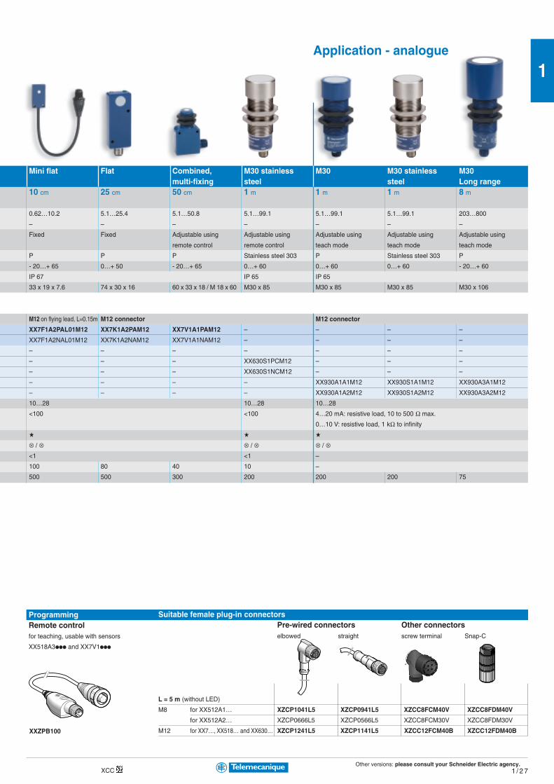
Other versions: please consult your Schneider Electric agency.1 / 2 7
1
Suitable female plug-in connectorsPre-wired connectors Other connectorselbowed straight screw terminal Snap-C
L = 5 m (without LED)
M8 for XX512A1… XZCP1041L5 XZCP0941L5 XZCC8FCM40V XZCC8FDM40V
for XX512A2… XZCP0666L5 XZCP0566L5 XZCC8FCM30V XZCC8FDM30V
M12 for XX7…, XX518… and XX630… XZCP1241L5 XZCP1141L5 XZCC12FCM40B XZCC12FDM40B
XCC
Mini flat Flat Combined, M30 stainless M30 M30 stainless M30multi-fixing steel steel Long range
10 cm 25 cm 50 cm 1 m 1 m 1 m 8 m
0.62…10.2 5.1…25.4 5.1…50.8 5.1…99.1 5.1…99.1 5.1…99.1 203…800
– – – – – – –
Fixed Fixed Adjustable using Adjustable using Adjustable using Adjustable using Adjustable using
remote control remote control teach mode teach mode teach mode
P P P Stainless steel 303 P Stainless steel 303 P
- 20…+ 65 0…+ 50 - 20…+ 65 0…+ 60 0…+ 60 0…+ 60 - 20…+ 60
IP 67 IP 65 IP 65
33 x 19 x 7.6 74 x 30 x 16 60 x 33 x 18 / M 18 x 60 M30 x 85 M30 x 85 M30 x 85 M30 x 106
M12 on flying lead, L=0.15m M12 connector M12 connector
XX7F1A2PAL01M12 XX7K1A2PAM12 XX7V1A1PAM12 – – – –
XX7F1A2NAL01M12 XX7K1A2NAM12 XX7V1A1NAM12 – – – –
– – – – – – –
– – – XX630S1PCM12 – – –
– – – XX630S1NCM12 – – –
– – – – XX930A1A1M12 XX930S1A1M12 XX930A3A1M12
– – – – XX930A1A2M12 XX930S1A2M12 XX930A3A2M12
10…28 10…28 10…28
<100 <100 4…20 mA: resistive load, 10 to 500 Ω max.
0…10 V: resistive load, 1 kΩ to infinity
⊗ / ⊗ ⊗ / ⊗ ⊗ / ⊗<1 <1 –
100 80 40 10 –
500 500 300 200 200 200 75
ProgrammingRemote controlfor teaching, usable with sensors
XX518A3ppp and XX7V1ppp
XXZPB100
Application - analogue
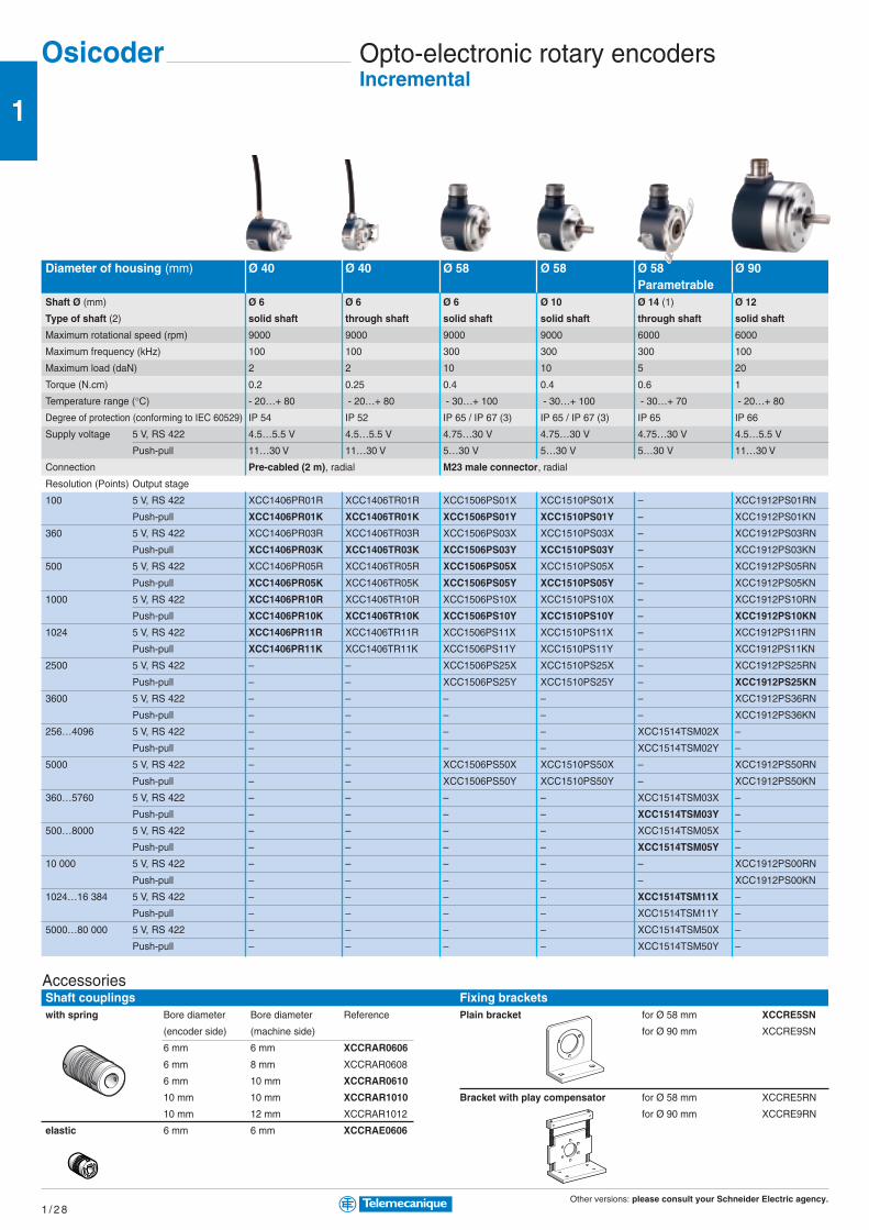
Other versions: please consult your Schneider Electric agency.1 / 2 8
1
Osicoder Opto-electronic rotary encodersIncremental
Shaft couplingswith spring Bore diameter Bore diameter Reference
(encoder side) (machine side)
6 mm 6 mm XCCRAR0606
6 mm 8 mm XCCRAR0608
6 mm 10 mm XCCRAR0610
10 mm 10 mm XCCRAR1010
10 mm 12 mm XCCRAR1012
elastic 6 mm 6 mm XCCRAE0606
Diameter of housing (mm) Ø 40 Ø 40 Ø 58 Ø 58 Ø 58 Ø 90Parametrable
Shaft Ø (mm) Ø 6 Ø 6 Ø 6 Ø 10 Ø 14 (1) Ø 12
Type of shaft (2) solid shaft through shaft solid shaft solid shaft through shaft solid shaft
Maximum rotational speed (rpm) 9000 9000 9000 9000 6000 6000
Maximum frequency (kHz) 100 100 300 300 300 100
Maximum load (daN) 2 2 10 10 5 20
Torque (N.cm) 0.2 0.25 0.4 0.4 0.6 1
Temperature range (°C) - 20…+ 80 - 20…+ 80 - 30…+ 100 - 30…+ 100 - 30…+ 70 - 20…+ 80
Degree of protection (conforming to IEC 60529) IP 54 IP 52 IP 65 / IP 67 (3) IP 65 / IP 67 (3) IP 65 IP 66
Supply voltage 5 V, RS 422 4.5…5.5 V 4.5…5.5 V 4.75…30 V 4.75…30 V 4.75…30 V 4.5…5.5 V
Push-pull 11…30 V 11…30 V 5…30 V 5…30 V 5…30 V 11…30 V
Connection Pre-cabled (2 m), radial M23 male connector, radial
Resolution (Points) Output stage
100 5 V, RS 422 XCC1406PR01R XCC1406TR01R XCC1506PS01X XCC1510PS01X – XCC1912PS01RN
Push-pull XCC1406PR01K XCC1406TR01K XCC1506PS01Y XCC1510PS01Y – XCC1912PS01KN
360 5 V, RS 422 XCC1406PR03R XCC1406TR03R XCC1506PS03X XCC1510PS03X – XCC1912PS03RN
Push-pull XCC1406PR03K XCC1406TR03K XCC1506PS03Y XCC1510PS03Y – XCC1912PS03KN
500 5 V, RS 422 XCC1406PR05R XCC1406TR05R XCC1506PS05X XCC1510PS05X – XCC1912PS05RN
Push-pull XCC1406PR05K XCC1406TR05K XCC1506PS05Y XCC1510PS05Y – XCC1912PS05KN
1000 5 V, RS 422 XCC1406PR10R XCC1406TR10R XCC1506PS10X XCC1510PS10X – XCC1912PS10RN
Push-pull XCC1406PR10K XCC1406TR10K XCC1506PS10Y XCC1510PS10Y – XCC1912PS10KN
1024 5 V, RS 422 XCC1406PR11R XCC1406TR11R XCC1506PS11X XCC1510PS11X – XCC1912PS11RN
Push-pull XCC1406PR11K XCC1406TR11K XCC1506PS11Y XCC1510PS11Y – XCC1912PS11KN
2500 5 V, RS 422 – – XCC1506PS25X XCC1510PS25X – XCC1912PS25RN
Push-pull – – XCC1506PS25Y XCC1510PS25Y – XCC1912PS25KN
3600 5 V, RS 422 – – – – – XCC1912PS36RN
Push-pull – – – – – XCC1912PS36KN
256…4096 5 V, RS 422 – – – – XCC1514TSM02X –
Push-pull – – – – XCC1514TSM02Y –
5000 5 V, RS 422 – – XCC1506PS50X XCC1510PS50X – XCC1912PS50RN
Push-pull – – XCC1506PS50Y XCC1510PS50Y – XCC1912PS50KN
360…5760 5 V, RS 422 – – – – XCC1514TSM03X –
Push-pull – – – – XCC1514TSM03Y –
500…8000 5 V, RS 422 – – – – XCC1514TSM05X –
Push-pull – – – – XCC1514TSM05Y –
10 000 5 V, RS 422 – – – – – XCC1912PS00RN
Push-pull – – – – – XCC1912PS00KN
1024…16 384 5 V, RS 422 – – – – XCC1514TSM11X –
Push-pull – – – – XCC1514TSM11Y –
5000…80 000 5 V, RS 422 – – – – XCC1514TSM50X –
Push-pull – – – – XCC1514TSM50Y –
AccessoriesFixing bracketsPlain bracket for Ø 58 mm XCCRE5SN
for Ø 90 mm XCCRE9SN
Bracket with play compensator for Ø 58 mm XCCRE5RN
for Ø 90 mm XCCRE9RN
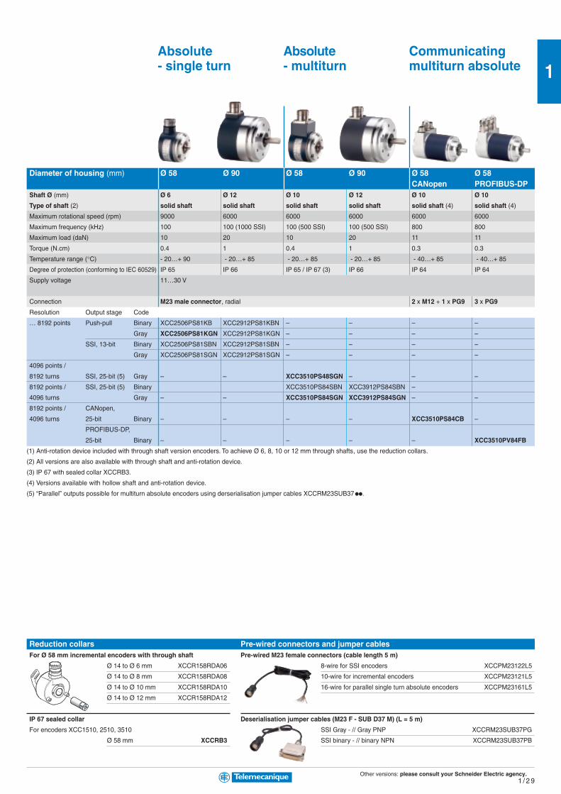
Other versions: please consult your Schneider Electric agency.1 / 2 9
1Absolute Absolute Communicating- single turn - multiturn multiturn absolute
Diameter of housing (mm) Ø 58 Ø 90 Ø 58 Ø 90 Ø 58 Ø 58CANopen PROFIBUS-DP
Shaft Ø (mm) Ø 6 Ø 12 Ø 10 Ø 12 Ø 10 Ø 10
Type of shaft (2) solid shaft solid shaft solid shaft solid shaft solid shaft (4) solid shaft (4)
Maximum rotational speed (rpm) 9000 6000 6000 6000 6000 6000
Maximum frequency (kHz) 100 100 (1000 SSI) 100 (500 SSI) 100 (500 SSI) 800 800
Maximum load (daN) 10 20 10 20 11 11
Torque (N.cm) 0.4 1 0.4 1 0.3 0.3
Temperature range (°C) - 20…+ 90 - 20…+ 85 - 20…+ 85 - 20…+ 85 - 40…+ 85 - 40…+ 85
Degree of protection (conforming to IEC 60529) IP 65 IP 66 IP 65 / IP 67 (3) IP 66 IP 64 IP 64
Supply voltage 11…30 V
Connection M23 male connector, radial 2 x M12 + 1 x PG9 3 x PG9
Resolution Output stage Code
… 8192 points Push-pull Binary XCC2506PS81KB XCC2912PS81KBN – – – –
Gray XCC2506PS81KGN XCC2912PS81KGN – – – –
SSI, 13-bit Binary XCC2506PS81SBN XCC2912PS81SBN – – – –
Gray XCC2506PS81SGN XCC2912PS81SGN – – – –
4096 points /
8192 turns SSI, 25-bit (5) Gray – – XCC3510PS48SGN – – –
8192 points / SSI, 25-bit (5) Binary XCC3510PS84SBN XCC3912PS84SBN –
4096 turns Gray – – XCC3510PS84SGN XCC3912PS84SGN – –
8192 points / CANopen,
4096 turns 25-bit Binary – – – – XCC3510PS84CB –
PROFIBUS-DP,
25-bit Binary – – – – – XCC3510PV84FB
(1) Anti-rotation device included with through shaft version encoders. To achieve Ø 6, 8, 10 or 12 mm through shafts, use the reduction collars.
(2) All versions are also available with through shaft and anti-rotation device.
(3) IP 67 with sealed collar XCCRB3.
(4) Versions available with hollow shaft and anti-rotation device.
(5) “Parallel” outputs possible for multiturn absolute encoders using derserialisation jumper cables XCCRM23SUB37pp.
Reduction collarsFor Ø 58 mm incremental encoders with through shaft
Ø 14 to Ø 6 mm XCCR158RDA06
Ø 14 to Ø 8 mm XCCR158RDA08
Ø 14 to Ø 10 mm XCCR158RDA10
Ø 14 to Ø 12 mm XCCR158RDA12
IP 67 sealed collar
For encoders XCC1510, 2510, 3510
Ø 58 mm XCCRB3
Pre-wired connectors and jumper cablesPre-wired M23 female connectors (cable length 5 m)
8-wire for SSI encoders XCCPM23122L5
10-wire for incremental encoders XCCPM23121L5
16-wire for parallel single turn absolute encoders XCCPM23161L5
Deserialisation jumper cables (M23 F - SUB D37 M) (L = 5 m)
SSI Gray - // Gray PNP XCCRM23SUB37PG
SSI binary - // binary NPN XCCRM23SUB37PB
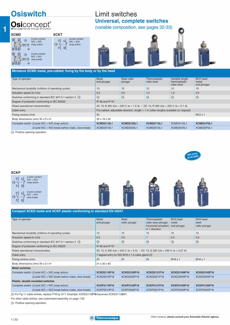
Other versions: please consult your Schneider Electric agency.1 / 3 0
1
1314 22
21
BK
WH
BK
BU
BN
GN-YE
BK
WH
BK
BU
BN
GN-YE
ISO entry
(to EN 50262)
1314 22
21
1314 22
21
Osiswitch Limit switchesUniversal, complete switches(variable composition, see pages 32-33)
Miniature XCMD metal, pre-cabled; fixing by the body or by the head
Type of operator Metal Steel roller Thermoplastic Variable length M12 headend plunger plunger roller lever thermoplastic metal
roller lever end plungerMechanical durability (millions of operating cycles) 10 10 10 10 10
Actuation speed (in m/s) 0.5 0.5 1.5 1.5 0.5
Switches conforming to standard IEC 947-5-1 section 3
Degree of protection conforming to IEC 60529 IP 66 and IP 67
Rated operational characteristics AC 15; B 300 (Ue = 240 V, Ie = 1.5 A) / DC 13; R 300 (Ue = 250 V, Ie = 0.1 A)
Cable entry Pre-cabled, adjustable direction, length = 1 m (other lengths available on request)
Fixing centres (mm) 20 M12 x 1
Body dimensions (mm) W x D x H 30 x 16 x 50
Complete switch (2-pole N/C + N/O snap action) XCMD2110L1 XCMD2102L1 XCMD2115L1 XCMD2145L1 XCMD21F0L1
(2-pole N/C + N/O break before make, slow break) XCMD2510L1 XCMD2502L1 XCMD2515L1 XCMD2545L1 XCMD25F0L1
Positive opening operation.
Compact XCKD metal and XCKP plastic conforming to standard EN 50047
Type of operator Metal Steel Thermoplastic M18 head M18 headend plunger roller plunger roller lever plunger, metal steel
horizontal actuation end plunger roller plungerin 1 direction
Mechanical durability (millions of operating cycles) 15 10 15 10 10
Actuation speed (in m/s) 0.5 0.5 1 0.5 0.5
Switches conforming to standard IEC 947-5-1 section 3
Degree of protection conforming to IEC 60529 IP 66 and IP 67
Rated operational characteristics AC 15; A 300 (Ue = 240 V, Ie = 3 A) / DC 13; Q 300 (Ue = 250 V, Ie = 0.27 A)
Cable entry 1 tapped entry for ISO M16 x 1.5 cable gland (2)
Fixing centres (mm) 20 20 20 M18 x 1 M18 x 1
Body dimensions (mm) W x D x H 31 x 30 x 65
Metal switches
Complete switch (2-pole N/C + N/O snap action) XCKD2110P16 XCKD2102P16 XCKD2121P16 XCKD21H0P16 XCKD21H2P16
(2-pole N/C + N/O break before make, slow break) XCKD2510P16 XCKD2502P16 XCKD2521P16 XCKD25H0P16 XCKD25H2P16
Plastic, double insulated switches
Complete switch (2-pole N/C + N/O snap action) XCKP2110P16 XCKP2102P16 XCKP2121P16 XCKP21H0P16 XCKP21H2P16
(2-pole N/C + N/O break before make, slow break) XCKP2510P16 XCKP2502P16 XCKP2521P16 XCKP25H0P16 XCKP25H2P16
(2) For Pg 11 cable entries, replace P16 by G11. Example: XCKD2110P16 becomes XCKD2110G11.
For other cable entries, see customised assembly on page 1/32.
Positive opening operation.
XCMD2-pole contactN/C + N/Osnap action
2-pole contactN/C + N/Oslow break
XCKT2-pole contactN/C + N/Osnap action
XCKP2-pole contactN/C + N/Osnap action
2-pole contactN/C + N/Oslow break
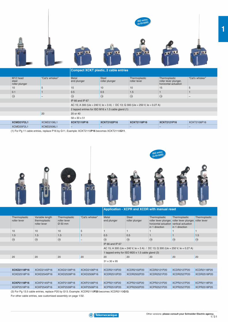
Other versions: please consult your Schneider Electric agency.1 / 3 1
1ISO entry
(to EN 50262)
ISO entry
(to EN 50262)
Compact XCKT plastic, 2 cable entries
M12 head “Cat’s whisker” Metal Steel Thermoplastic Thermoplastic “Cat’s whisker”steel end plunger roller plunger roller lever roller lever plunger,roller plunger horizontal actuation10 5 15 10 10 15 5
0.1 1 0.5 0.5 1.5 1 1
– –
IP 66 and IP 67
AC 15; A 300 (Ue = 240 V, Ie = 3 A) / DC 13; Q 300 (Ue = 250 V, Ie = 0.27 A)
2 tapped entries for ISO M16 x 1.5 cable gland (1)
20 20 or 40
58 x 30 x 51
XCMD21F2L1 XCMD2106L1 XCKT2110P16 XCKT2102P16 XCKT2118P16 XCKT2121P16 XCKT2106P16
XCMD25F2L1 XCMD2506L1 – – – – –
(1) For Pg 11 cable entries, replace P16 by G11. Example: XCKT2110P16 becomes XCKT2110G11.
Application - XCPR and XCDR with manual reset
Thermoplastic Variable length Thermoplastic “Cat’s whisker” Metal Steel Thermoplastic Thermoplastic Thermoplasticroller lever thermoplastic roller lever end plunger roller plunger roller lever plunger, roller lever plunger, roller lever
roller lever Ø 50 mm horizontal actuation vertical actuationin 1 direction in 1 direction
10 10 10 5 1 1 1 1 1
1.5 1.5 1.5 1 0.5 0.5 1 1 1.5
–
IP 66 and IP 67
AC 15; A 300 (Ue = 240 V, Ie = 3 A) / DC 13; Q 300 (Ue = 250 V, Ie = 0.27 A)
1 tapped entry for ISO M20 x 1.5 cable gland (3)
20 20 20 20 20 20 20 20 20
31 x 30 x 95
XCKD2118P16 XCKD2145P16 XCKD2139P16 XCKD2106P16 XCDR2110P20 XCDR2102P20 XCDR2121P20 XCDR2127P20 XCDR2118P20
XCKD2518P16 XCKD2545P16 XCKD2539P16 XCKD2506P16 XCDR2510P20 XCDR2502P20 XCDR2521P20 XCDR2527P20 XCDR2518P20
XCKP2118P16 XCKP2145P16 XCKP2139P16 XCKP2106P16 XCPR2110P20 XCPR2102P20 XCPR2121P20 XCPR2127P20 XCPR2118P20
XCKP2518P16 XCKP2545P16 XCKP2539P16 XCKP2506P16 XCPR2510P20 XCPR2502P20 XCPR2521P20 XCPR2527P20 XCPR2518P20
(3) For Pg 13.5 cable entries, replace P20 by G13. Example: XCDR2110P20 becomes XCDR2110G13.
For other cable entries, see customised assembly on page 1/32.
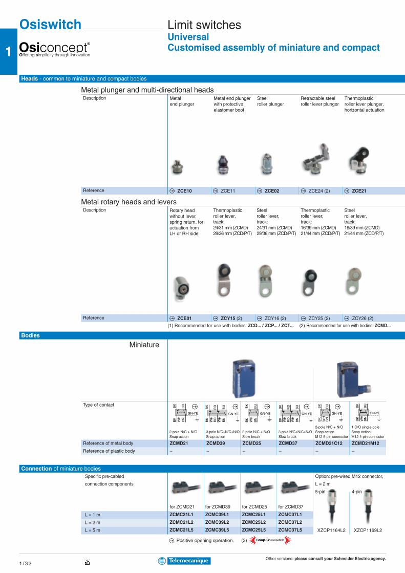
Other versions: please consult your Schneider Electric agency.1 / 3 2
1
BK
WH
BK
BU
BN
GN-YE
BK
WH
BK
BU
BN
GN-YE
RD
WH
RD
BU
BN
GN-YE
BK
WH
BK
BK
WH
BK
BU
BN
GN-YE
RD
WH
RD
BU
BN
GN-YE
BK
WH
BK
Snap-C® compatible(3)
BK
WH
BK
BU
BN
GN-YE
Osiswitch Limit switchesUniversalCustomised assembly of miniature and compact
Thermoplasticroller lever plunger,horizontal actuation
Metalend plunger
Steelroller plunger
Retractable steelroller lever plunger
Metal end plungerwith protectiveelastomer boot
Metal plunger and multi-directional heads
Heads - common to miniature and compact bodies
Description
Reference
Bodies
Connection of miniature bodies
Metal rotary heads and leversRotary headwithout lever,spring return, foractuation fromLH or RH side
Steelroller lever,track:24/31 mm (ZCMD)29/36 mm (ZCD/P/T)
Thermoplasticroller lever,track:16/39 mm (ZCMD)21/44 mm (ZCD/P/T)
Steelroller lever,track:16/39 mm (ZCMD)21/44 mm (ZCD/P/T)
Thermoplasticroller lever,track:24/31 mm (ZCMD)29/36 mm (ZCD/P/T)
Description
Reference
Type of contact
Reference of metal body
Reference of plastic body
ZCMD21 ZCMD39 ZCMD25 ZCMD37 ZCMD21C12 ZCMD21M12
– – – – – –
Miniature
Specific pre-cabled
connection components
L = 1 m
L = 2 m
L = 5 m
Option: pre-wired M12 connector,
L = 2 m
5-pin 4-pin
for ZCMD21 for ZCMD39 for ZCMD25 for ZCMD37
ZCMC21L1 ZCMC39L1 ZCMC25L1 ZCMC37L1
ZCMC21L2 ZCMC39L2 ZCMC25L2 ZCMC37L2
ZCMC21L5 ZCMC39L5 ZCMC25L5 ZCMC37L5
(1) Recommended for use with bodies: ZCD... / ZCP... / ZCT...
XZCP1164L2 XZCP1169L2
2-pole N/C + N/O 1 C/O single-pole2-pole N/C + N/O 3-pole N/C+N/C+N/O 2-pole N/C + N/O 3-pole N/C+N/C+N/O Snap action Snap actionSnap action Snap action Slow break Slow break M12 5-pin connector M12 4-pin connector
Positive opening operation.
(2) Recommended for use with bodies: ZCMD...
ZCE10 ZCE11 ZCE02 ZCE24 (2) ZCE21
ZCE01 ZCY15 (2) ZCY16 (2) ZCY25 (2) ZCY26 (2)

Other versions: please consult your Schneider Electric agency.1 / 3 3
1
13
14
22
21
3231
2221 13
14
1314 22
21 1314 22
21 13
14
22
21 13
14 2221
3231
2221 13
14
switches
Thermoplasticroller lever plunger,vertical actuation
M12 headmetalend plunger
M18 headmetalend plunger
M12 headsteelroller plunger
M18 headsteelroller plunger
Spring rod Spring rod withplastic end
“Cat’s whisker”
Thermoplasticroller lever,track:20/36 mm (ZCMD)24/40 mm (ZCD/P/T)
Steelroller lever,track:20/36 mm (ZCMD)24/40 mm (ZCD/P/T)
Ceramicroller lever
Variable lengththermoplasticroller lever
Round,glass fibrerod leverØ 3 mmL = 125 mm
Metalspring-rodlever
Thermoplasticroller leverØ 50 mm
Adjustable thermo-plastic roller lever Ø 50 mm
Interchangeableoutlet for cablegland
Description
Metal
Plastic
Option: pre-wired M12 connector,
L = 2 m
5-pin 4-pin
XZCP1164L2 XZCP1169L2
ZCT Pg 11 cable glandversions:replace the suffix P16 by G11.Example:ZCT21P16 becomes ZCT21G11
ZCT 1/2 NPT versions:replace the suffix P16 byN12 (adaptor).Example:ZCT21P16 becomes ZCT21N12
For ISO M16 For ISO M20 For Pg 11 For Pg 13.5 For 1/2” NPT For PF 1/2 (G12)
cable gland cable gland cable gland cable gland cable gland cable gland
ZCDEP16 ZCDEP20 ZCDEG11 ZCDEG13 ZCDEN12 ZCDEF12
ZCPEP16 ZCPEP20 ZCPEG11 ZCPEG13 ZCPEN12 ZCPEF12
2-pole N/C + N/O 3-pole N/C + N/C + N/O 2-pole N/C + N/O 3-pole N/C + N/C + N/O 2-pole N/C + N/O - Snap action 2-pole N/C + N/O 2-pole N/C+N/OSnap action Snap action Slow break Slow break 5-pin connector 4-pin connector (3) Snap action Slow break
ZCD21 ZCD39 ZCD25 ZCD37 ZCD21M12 – – –
ZCP21 ZCP39 ZCP25 ZCP37 – ZCP21M12 ZCT21P16 ZCT25P16
Compact
Type of contact
Ref. metal body
Ref. plastic body
Connection of compact bodies
ZCE27 ZCEF0 (2) ZCEH0 (1) ZCEF2 (2) ZCEH2 (1) ZCE08 ZCE07 ZCE06
ZCY18 (1) ZCY19 (1) ZCY22 ZCY45 ZCY55 ZCY91 ZCY39 ZCY49
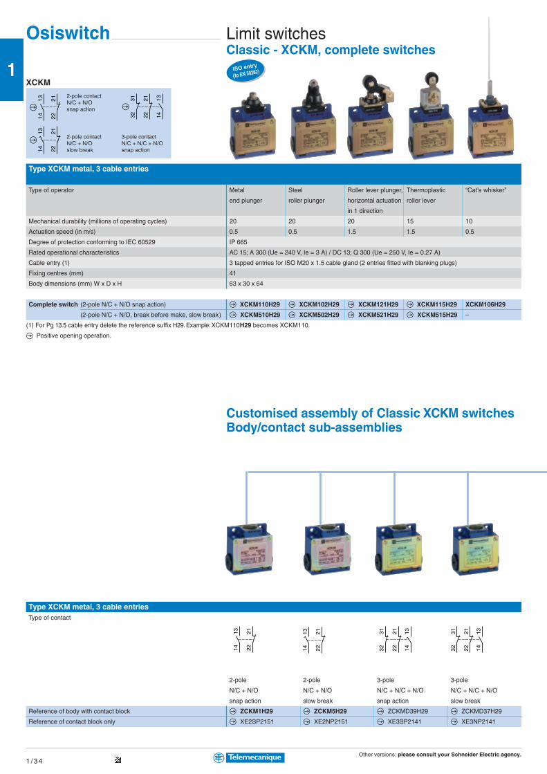
Other versions: please consult your Schneider Electric agency.1 / 3 4
1
13
14
22
21
13
14
22
21
3132
2122 14
13
222113
14 222113
14 3231
2221 13
14 3231
2221 13
14
Osiswitch Limit switchesClassic - XCKM, complete switches
Type XCKM metal, 3 cable entries
Type of operator Metal Steel Roller lever plunger, Thermoplastic “Cat’s whisker”
end plunger roller plunger horizontal actuation roller lever
in 1 direction
Mechanical durability (millions of operating cycles) 20 20 20 15 10
Actuation speed (in m/s) 0.5 0.5 1.5 1.5 0.5
Degree of protection conforming to IEC 60529 IP 665
Rated operational characteristics AC 15; A 300 (Ue = 240 V, Ie = 3 A) / DC 13; Q 300 (Ue = 250 V, Ie = 0.27 A)
Cable entry (1) 3 tapped entries for ISO M20 x 1.5 cable gland (2 entries fitted with blanking plugs)
Fixing centres (mm) 41
Body dimensions (mm) W x D x H 63 x 30 x 64
Complete switch (2-pole N/C + N/O snap action) XCKM110H29 XCKM102H29 XCKM121H29 XCKM115H29 XCKM106H29
(2-pole N/C + N/O, break before make, slow break) XCKM510H29 XCKM502H29 XCKM521H29 XCKM515H29 –
(1) For Pg 13.5 cable entry delete the reference suffix H29. Example: XCKM110H29 becomes XCKM110.
Positive opening operation.
Customised assembly of Classic XCKM switchesBody/contact sub-assemblies
Type XCKM metal, 3 cable entriesType of contact
2-pole 2-pole 3-pole 3-pole
N/C + N/O N/C + N/O N/C + N/C + N/O N/C + N/C + N/O
snap action slow break snap action slow break
Reference of body with contact block ZCKM1H29 ZCKM5H29 ZCKMD39H29 ZCKMD37H29
Reference of contact block only XE2SP2151 XE2NP2151 XE3SP2141 XE3NP2141
XCKM
2-pole contactN/C + N/Osnap action
2-pole contactN/C + N/Oslow break
3-pole contactN/C + N/C + N/Osnap action
ISO entry
(to EN 50262)

Other versions: please consult your Schneider Electric agency.1 / 3 5
1
Complete switch = Body/contact assembly + Head + Lever
Rotary or multi-directional headswith thermoplastic with steel roller with variable length with Ø 6 mm with thermoplastic with “Cat’s with spring rod
roller lever (2) lever (2) thermoplastic thermoplastic rod roller lever (3) whisker”
roller lever (2) L = 200 mm (3) for actuation from
left AND right
or
left OR right
Reference ZCKD15 ZCKD16 ZCKD41 ZCKD59 ZCKD31 ZCKD06 ZCKD08
Plunger headswith metal with metal with steel with thermoplastic with steel
end plunger end plunger roller plunger roller lever plunger, roller lever plunger,
and protective horizontal actuation horizontal actuation
boot in 1 direction in 1 direction
Reference ZCKD10 ZCKD109 ZCKD02 ZCKD21 ZCKD23
Rotary heads and separate leversspring return, lever with lever with variable length variable length rod, Ø 6 mm
for actuation from thermoplastic steel roller (2) lever with lever with thermoplastic
left AND right roller (2) thermoplastic steel roller (2) L = 200 mm (3)
or roller (2)
left OR right
Reference ZCKD05 ZCKY31 ZCKY33 ZCKY41 ZCKY43 ZCKY59
(2) Adjustable throughout 360° in 5° steps, or in 90° steps by reversing the notched washer.
(3) Adjustable throughout 360° in 5° steps, or in 45° steps by reversing the lever mounting.
Customised assembly of Classic XCKMswitchesOperating heads,complete or for customer assembly
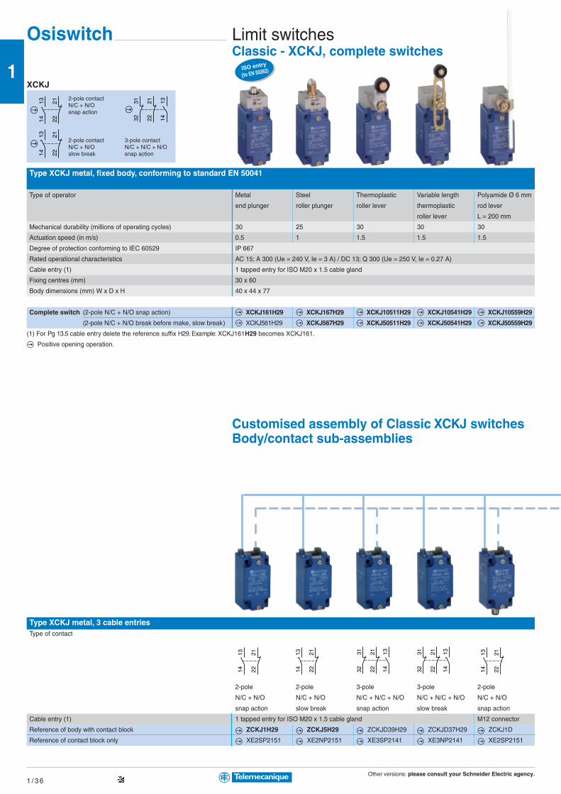
Other versions: please consult your Schneider Electric agency.1 / 3 6
1
13
14
22
21
13
14
22
21
3132
2122 14
13
222113
14 222113
14222113
14 3231
2221 13
143231
2221 13
14
Osiswitch Limit switchesClassic - XCKJ, complete switches
XCKJ
2-pole contactN/C + N/Osnap action
2-pole contactN/C + N/Oslow break
3-pole contactN/C + N/C + N/Osnap action
Type XCKJ metal, fixed body, conforming to standard EN 50041
Type of operator Metal Steel Thermoplastic Variable length Polyamide Ø 6 mm
end plunger roller plunger roller lever thermoplastic rod lever
roller lever L = 200 mm
Mechanical durability (millions of operating cycles) 30 25 30 30 30
Actuation speed (in m/s) 0.5 1 1.5 1.5 1.5
Degree of protection conforming to IEC 60529 IP 667
Rated operational characteristics AC 15; A 300 (Ue = 240 V, Ie = 3 A) / DC 13; Q 300 (Ue = 250 V, Ie = 0.27 A)
Cable entry (1) 1 tapped entry for ISO M20 x 1.5 cable gland
Fixing centres (mm) 30 x 60
Body dimensions (mm) W x D x H 40 x 44 x 77
Complete switch (2-pole N/C + N/O snap action) XCKJ161H29 XCKJ167H29 XCKJ10511H29 XCKJ10541H29 XCKJ10559H29
(2-pole N/C + N/O break before make, slow break) XCKJ561H29 XCKJ567H29 XCKJ50511H29 XCKJ50541H29 XCKJ50559H29
(1) For Pg 13.5 cable entry delete the reference suffix H29. Example: XCKJ161H29 becomes XCKJ161.
Positive opening operation.
Customised assembly of Classic XCKJ switchesBody/contact sub-assemblies
Type XCKJ metal, 3 cable entriesType of contact
2-pole 2-pole 3-pole 3-pole 2-pole
N/C + N/O N/C + N/O N/C + N/C + N/O N/C + N/C + N/O N/C + N/O
snap action slow break snap action slow break snap action
Cable entry (1) 1 tapped entry for ISO M20 x 1.5 cable gland M12 connector
Reference of body with contact block ZCKJ1H29 ZCKJ5H29 ZCKJD39H29 ZCKJD37H29 ZCKJ1D
Reference of contact block only XE2SP2151 XE2NP2151 XE3SP2141 XE3NP2141 XE2SP2151
ISO entry
(to EN 50262)
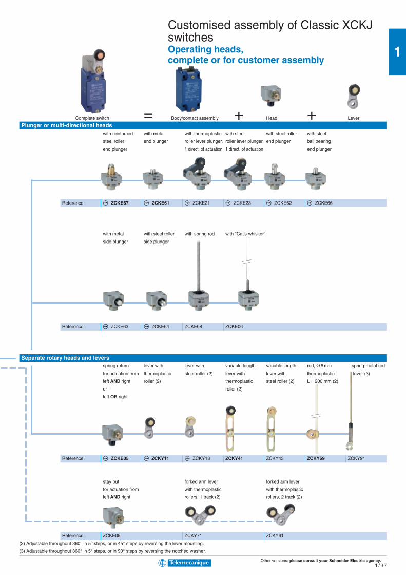
Other versions: please consult your Schneider Electric agency.1 / 3 7
1
Complete switch = Body/contact assembly + Head + Lever
Plunger or multi-directional headswith reinforced with metal with thermoplastic with steel with steel roller with steel
steel roller end plunger roller lever plunger, roller lever plunger, end plunger ball bearing
end plunger 1 direct. of actuation 1 direct. of actuation end plunger
Reference ZCKE67 ZCKE61 ZCKE21 ZCKE23 ZCKE62 ZCKE66
with metal with steel roller with spring rod with “Cat’s whisker”
side plunger side plunger
Reference ZCKE63 ZCKE64 ZCKE08 ZCKE06
Separate rotary heads and leversspring return lever with lever with variable length variable length rod, Ø 6 mm spring-metal rod
for actuation from thermoplastic steel roller (2) lever with lever with thermoplastic lever (3)
left AND right roller (2) thermoplastic steel roller (2) L = 200 mm (2)
or roller (2)
left OR right
Reference ZCKE05 ZCKY11 ZCKY13 ZCKY41 ZCKY43 ZCKY59 ZCKY91
stay put forked arm lever forked arm lever
for actuation from with thermoplastic with thermoplastic
left AND right rollers, 1 track (2) rollers, 2 track (2)
Reference ZCKE09 ZCKY71 ZCKY61
(2) Adjustable throughout 360° in 5° steps, or in 45° steps by reversing the lever mounting.
(3) Adjustable throughout 360° in 5° steps, or in 90° steps by reversing the notched washer.
Customised assembly of Classic XCKJswitchesOperating heads,complete or for customer assembly

Other versions: please consult your Schneider Electric agency.1 / 3 8
1 1314 22
21
1314 22
21
3132
2122 14
13 1314 22
21 1314 22
21
1112 22
21 1112 22
21
121113
14 222123
24121113
14
ISO entry
(to EN 50262)
Osiswitch Limit switchesClassic - XCKS, complete switches
Type XCKS plastic, double insulated, conforming to standard EN 50041
Type of operator Metal Steel Thermoplastic Variable length Rubber Polyamide Ø 6 mm
end plunger roller plunger roller lever thermoplastic roller lever rod lever
roller lever Ø 50 mm L = 200 mm
Mechanical durability (millions of operating cycles) 25 15 20 20 20 20
Actuation speed (in m/s) 0.5 0.5 1.5 1.5 1 1
Degree of protection conforming to IEC 60529 IP 653
Rated operational characteristics AC 15; A 300 (Ue = 240 V, Ie = 3 A) / DC 13; Q 300 (Ue = 250 V, Ie = 0.27 A)
Cable entry (1) 1 tapped entry for ISO M20 x 1.5 cable gland
Fixing centres (mm) 30 x 60
Body dimensions (mm) W x D x H 40 x 36 x 72.5
Complete switch (2-pole N/C + N/O snap action) XCKS101H29 XCKS102H29 XCKS131H29 XCKS141H29 XCKS139H29 XCKS159H29
(2-pole N/C + N/O break before make, slow break) XCKS501H29 XCKS502H29 XCKS531H29 XCKS541H29 XCKS539H29 XCKS559H29
Body (2-pole N/C + N/O snap action) ZCKS1H29 ZCKS1H29 ZCKS1H29 ZCKS1H29 ZCKS1H29 ZCKS1H29
(2-pole N/C + N/O break before make, slow break) ZCKS5H29 ZCKS5H29 ZCKS5H29 ZCKS5H29 ZCKS5H29 ZCKS5H29
(3-pole N/C + N/C + N/O snap action) ZCKSD39H29 ZCKSD39H29 ZCKSD39H29 ZCKSD39H29 ZCKSD39H29 ZCKSD39H29
Associated head (including operator) ZCKD01 ZCKD02 ZCKD31 ZCKD41 ZCKD39 ZCKD59
Operating lever for rotary head – – ZCKY31 ZCKY41 ZCKY39 ZCKY59
Complete switch with 2-pole snap action contacts
(2 x N/C + N/O contacts actuated in each direction) – – – – – –
(1 x N/C + N/O contact actuated in each direction) – – – – – –
Complete switch (2 x single-pole C/O snap action contacts) – – – – – –
(2 x 2-pole N/C+N/C staggered, slow break contacts) – – – – – –
Positive opening operation. (1) For Pg 13.5 cable entry delete the reference suffix H29. Example: XCKJ161H29 becomes XCKJ161.
XC2J switches, customised assemblyBody/contact sub-assemblies
Type XC2J metal, fixed body, 1 cable entry incorporating cable glandType of contact
Single-pole Double-pole
1 C/O contact 2 C/O simultaneous contacts
snap action snap action
Reference of body with contact block ZC2JC1 ZC2JC2
Reference of contact block only XCKZ01 XESP1021
XCKS2-pole contactN/C + N/Osnap action
2-pole contactN/C + N/Oslow break
3-poleN/C + N/C + N/Osnap action
XCR
2 x 2-polecontacts,snap action
XCKMR2 x 2-polecontactsN/C + N/Cstaggered,slow break
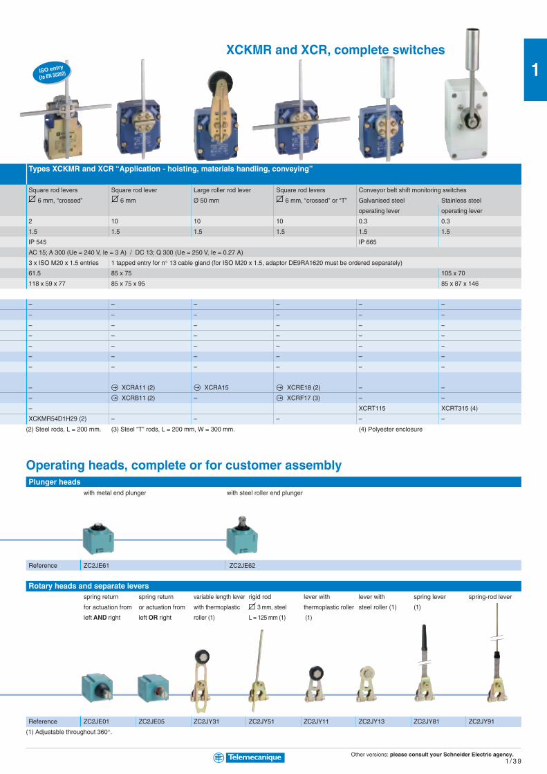
Other versions: please consult your Schneider Electric agency.1 / 3 9
1
Types XCKMR and XCR “Application - hoisting, materials handling, conveying”
Square rod levers Square rod lever Large roller rod lever Square rod levers Conveyor belt shift monitoring switches
6 mm, “crossed” 6 mm Ø 50 mm 6 mm, “crossed” or “T” Galvanised steel Stainless steel
operating lever operating lever
2 10 10 10 0.3 0.3
1.5 1.5 1.5 1.5 1.5 1.5
IP 545 IP 665
AC 15; A 300 (Ue = 240 V, Ie = 3 A) / DC 13; Q 300 (Ue = 250 V, Ie = 0.27 A)
3 x ISO M20 x 1.5 entries 1 tapped entry for n° 13 cable gland (for ISO M20 x 1.5, adaptor DE9RA1620 must be ordered separately)
61.5 85 x 75 105 x 70
118 x 59 x 77 85 x 75 x 95 85 x 87 x 146
– – – – – –
– – – – – –
– – – – – –
– – – – – –
– – – – – –
– – – – – –
– – – – – –
– XCRA11 (2) XCRA15 XCRE18 (2) – –
– XCRB11 (2) – XCRF17 (3) – –
– XCRT115 XCRT315 (4)
XCKMR54D1H29 (2) – – – – –
(2) Steel rods, L = 200 mm. (3) Steel “T” rods, L = 200 mm, W = 300 mm. (4) Polyester enclosure
Operating heads, complete or for customer assemblyPlunger heads
with metal end plunger with steel roller end plunger
Reference ZC2JE61 ZC2JE62
Rotary heads and separate leversspring return spring return variable length lever rigid rod lever with lever with spring lever spring-rod lever
for actuation from or actuation from with thermoplastic 3 mm, steel thermoplastic roller steel roller (1) (1)
left AND right left OR right roller (1) L = 125 mm (1) (1)
Reference ZC2JE01 ZC2JE05 ZC2JY31 ZC2JY51 ZC2JY11 ZC2JY13 ZC2JY81 ZC2JY91
(1) Adjustable throughout 360°.
ISO entry
(to EN 50262)
XCKMR and XCR, complete switches
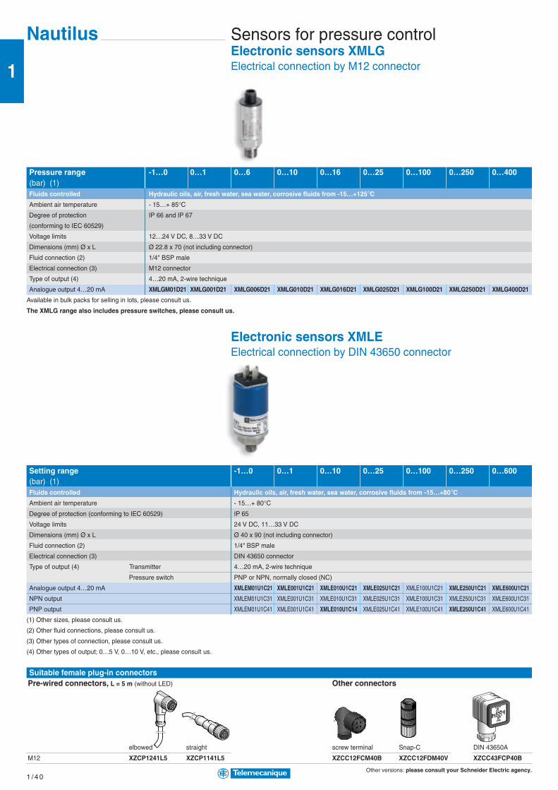
Other versions: please consult your Schneider Electric agency.1 / 4 0
1
Nautilus Sensors for pressure controlElectronic sensors XMLGElectrical connection by M12 connector
Pressure range -1…0 0…1 0…6 0…10 0…16 0…25 0…100 0…250 0…400(bar) (1)Fluids controlled Hydraulic oils, air, fresh water, sea water, corrosive fluids from -15…+125°CAmbient air temperature - 15…+ 85°CDegree of protection IP 66 and IP 67
(conforming to IEC 60529)
Voltage limits 12…24 V DC, 8…33 V DC
Dimensions (mm) Ø x L Ø 22.8 x 70 (not including connector)
Fluid connection (2) 1/4" BSP male
Electrical connection (3) M12 connector
Type of output (4) 4…20 mA, 2-wire technique
Analogue output 4…20 mA XMLGM01D21 XMLG001D21 XMLG006D21 XMLG010D21 XMLG016D21 XMLG025D21 XMLG100D21 XMLG250D21 XMLG400D21
Available in bulk packs for selling in lots, please consult us.
The XMLG range also includes pressure switches, please consult us.
Electronic sensors XMLEElectrical connection by DIN 43650 connector
Setting range -1…0 0…1 0…10 0…25 0…100 0…250 0…600(bar) (1)Fluids controlled Hydraulic oils, air, fresh water, sea water, corrosive fluids from -15…+80°CAmbient air temperature - 15…+ 80°CDegree of protection (conforming to IEC 60529) IP 65
Voltage limits 24 V DC, 11…33 V DC
Dimensions (mm) Ø x L Ø 40 x 90 (not including connector)
Fluid connection (2) 1/4" BSP male
Electrical connection (3) DIN 43650 connector
Type of output (4) Transmitter 4…20 mA, 2-wire technique
Pressure switch PNP or NPN, normally closed (NC)
Analogue output 4…20 mA XMLEM01U1C21 XMLE001U1C21 XMLE010U1C21 XMLE025U1C21 XMLE100U1C21 XMLE250U1C21 XMLE600U1C21
NPN output XMLEM01U1C31 XMLE001U1C31 XMLE010U1C31 XMLE025U1C31 XMLE100U1C31 XMLE250U1C31 XMLE600U1C31
PNP output XMLEM01U1C41 XMLE001U1C41 XMLE010U1C14 XMLE025U1C41 XMLE100U1C41 XMLE250U1C41 XMLE600U1C41
(1) Other sizes, please consult us.
(2) Other fluid connections, please consult us.
(3) Other types of connection, please consult us.
(4) Other types of output; 0…5 V, 0…10 V, etc., please consult us.
Suitable female plug-in connectorsPre-wired connectors, L = 5 m (without LED) Other connectors
elbowed straight screw terminal Snap-C DIN 43650A
M12 XZCP1241L5 XZCP1141L5 XZCC12FCM40B XZCC12FDM40V XZCC43FCP40B
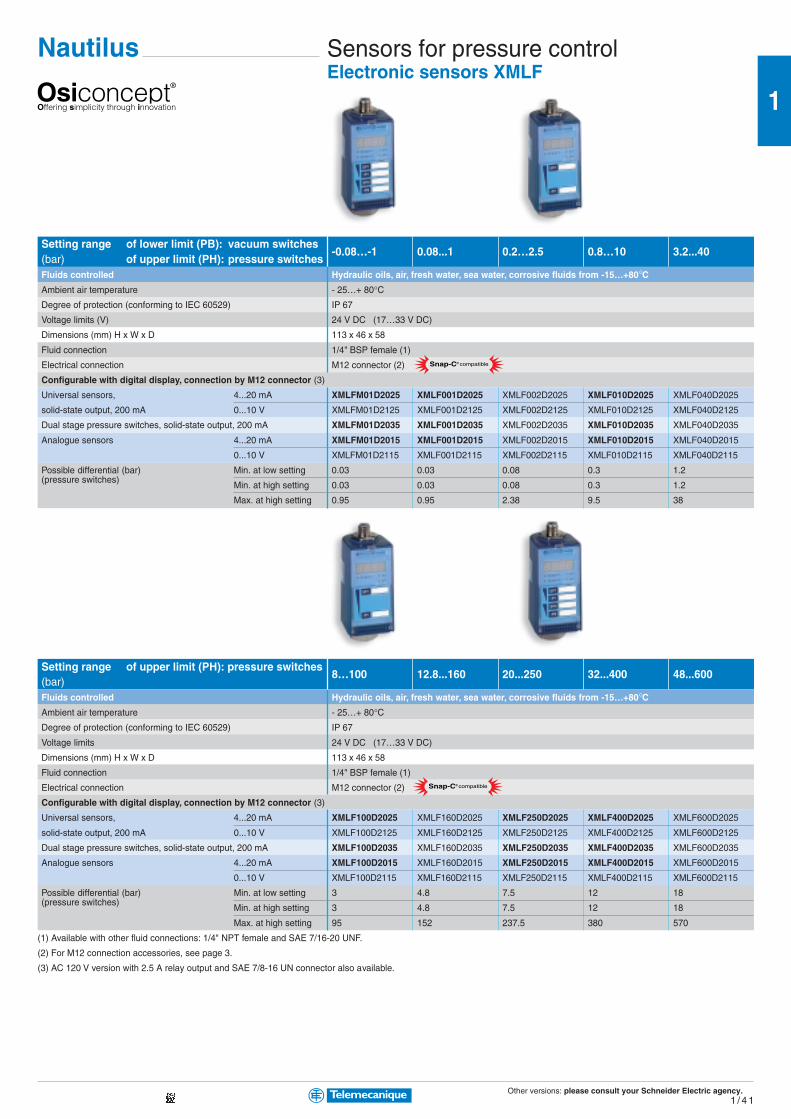
Other versions: please consult your Schneider Electric agency.1 / 4 1
1
Snap-C® compatible
Snap-C® compatible
Nautilus Sensors for pressure controlElectronic sensors XMLF
Setting range of lower limit (PB): vacuum switches-0.08…-1 0.08...1 0.2…2.5 0.8…10 3.2...40
(bar) of upper limit (PH): pressure switchesFluids controlled Hydraulic oils, air, fresh water, sea water, corrosive fluids from -15…+80°CAmbient air temperature - 25…+ 80°CDegree of protection (conforming to IEC 60529) IP 67
Voltage limits (V) 24 V DC (17…33 V DC)
Dimensions (mm) H x W x D 113 x 46 x 58
Fluid connection 1/4" BSP female (1)
Electrical connection M12 connector (2)
Configurable with digital display, connection by M12 connector (3)
Universal sensors, 4...20 mA XMLFM01D2025 XMLF001D2025 XMLF002D2025 XMLF010D2025 XMLF040D2025
solid-state output, 200 mA 0...10 V XMLFM01D2125 XMLF001D2125 XMLF002D2125 XMLF010D2125 XMLF040D2125
Dual stage pressure switches, solid-state output, 200 mA XMLFM01D2035 XMLF001D2035 XMLF002D2035 XMLF010D2035 XMLF040D2035
Analogue sensors 4...20 mA XMLFM01D2015 XMLF001D2015 XMLF002D2015 XMLF010D2015 XMLF040D2015
0...10 V XMLFM01D2115 XMLF001D2115 XMLF002D2115 XMLF010D2115 XMLF040D2115
Possible differential (bar) Min. at low setting 0.03 0.03 0.08 0.3 1.2(pressure switches)
Min. at high setting 0.03 0.03 0.08 0.3 1.2
Max. at high setting 0.95 0.95 2.38 9.5 38
Setting range of upper limit (PH): pressure switches8…100 12.8...160 20...250 32...400 48...600
(bar)Fluids controlled Hydraulic oils, air, fresh water, sea water, corrosive fluids from -15…+80°CAmbient air temperature - 25…+ 80°CDegree of protection (conforming to IEC 60529) IP 67
Voltage limits 24 V DC (17…33 V DC)
Dimensions (mm) H x W x D 113 x 46 x 58
Fluid connection 1/4" BSP female (1)
Electrical connection M12 connector (2)
Configurable with digital display, connection by M12 connector (3)
Universal sensors, 4...20 mA XMLF100D2025 XMLF160D2025 XMLF250D2025 XMLF400D2025 XMLF600D2025
solid-state output, 200 mA 0...10 V XMLF100D2125 XMLF160D2125 XMLF250D2125 XMLF400D2125 XMLF600D2125
Dual stage pressure switches, solid-state output, 200 mA XMLF100D2035 XMLF160D2035 XMLF250D2035 XMLF400D2035 XMLF600D2035
Analogue sensors 4...20 mA XMLF100D2015 XMLF160D2015 XMLF250D2015 XMLF400D2015 XMLF600D2015
0...10 V XMLF100D2115 XMLF160D2115 XMLF250D2115 XMLF400D2115 XMLF600D2115
Possible differential (bar) Min. at low setting 3 4.8 7.5 12 18(pressure switches)
Min. at high setting 3 4.8 7.5 12 18
Max. at high setting 95 152 237.5 380 570
(1) Available with other fluid connections: 1/4" NPT female and SAE 7/16-20 UNF.
(2) For M12 connection accessories, see page 3.
(3) AC 120 V version with 2.5 A relay output and SAE 7/8-16 UN connector also available.
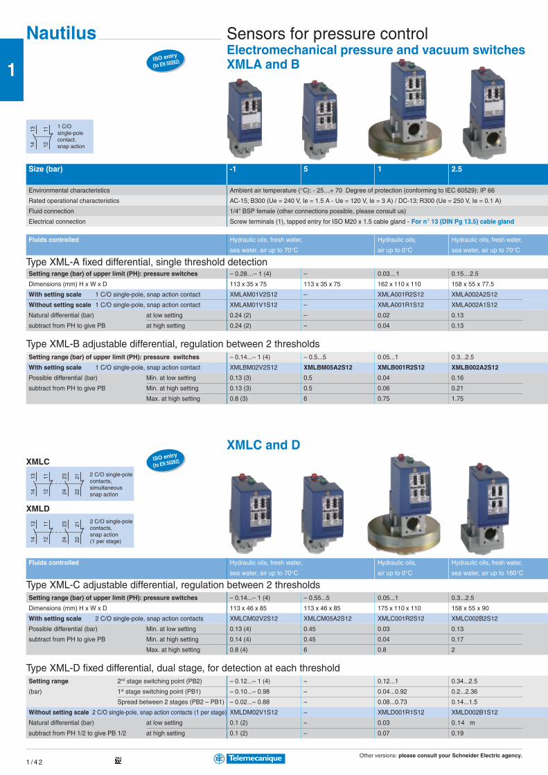
Other versions: please consult your Schneider Electric agency.1 / 4 2
1
121113
14
121113
14 222123
24
121113
14 222123
24ISO entry
(to EN 50262)
ISO entry
(to EN 50262)
Nautilus Sensors for pressure controlElectromechanical pressure and vacuum switchesXMLA and B
Size (bar) -1 5 1 2.5
Environmental characteristics Ambient air temperature (°C): - 25…+ 70 Degree of protection (conforming to IEC 60529): IP 66
Rated operational characteristics AC-15; B300 (Ue = 240 V, Ie = 1.5 A - Ue = 120 V, Ie = 3 A) / DC-13; R300 (Ue = 250 V, Ie = 0.1 A)
Fluid connection 1/4" BSP female (other connections possible, please consult us)
Electrical connection Screw terminals (1), tapped entry for ISO M20 x 1.5 cable gland - For n° 13 (DIN Pg 13.5) cable gland
Fluids controlled Hydraulic oils, fresh water, Hydraulic oils, Hydraulic oils, fresh water,
sea water, air up to 70°C air up to 0°C sea water, air up to 70°C
Type XML-A fixed differential, single threshold detectionSetting range (bar) of upper limit (PH): pressure switches – 0.28…– 1 (4) – 0.03…1 0.15…2.5
Dimensions (mm) H x W x D 113 x 35 x 75 113 x 35 x 75 162 x 110 x 110 158 x 55 x 77.5
With setting scale 1 C/O single-pole, snap action contact XMLAM01V2S12 – XMLA001R2S12 XMLA002A2S12
Without setting scale 1 C/O single-pole, snap action contact XMLAM01V1S12 – XMLA001R1S12 XMLA002A1S12
Natural differential (bar) at low setting 0.24 (2) – 0.02 0.13
subtract from PH to give PB at high setting 0.24 (2) – 0.04 0.13
Type XML-B adjustable differential, regulation between 2 thresholdsSetting range (bar) of upper limit (PH): pressure switches – 0.14...– 1 (4) – 0.5...5 0.05...1 0.3...2.5
With setting scale 1 C/O single-pole, snap action contact XMLBM02V2S12 XMLBM05A2S12 XMLB001R2S12 XMLB002A2S12
Possible differential (bar) Min. at low setting 0.13 (3) 0.5 0.04 0.16
subtract from PH to give PB Min. at high setting 0.13 (3) 0.5 0.06 0.21
Max. at high setting 0.8 (3) 6 0.75 1.75
XMLC and D
Fluids controlled Hydraulic oils, fresh water, Hydraulic oils, Hydraulic oils, fresh water,
sea water, air up to 70°C air up to 0°C sea water, air up to 160°C
Type XML-C adjustable differential, regulation between 2 thresholdsSetting range (bar) of upper limit (PH): pressure switches – 0.14...– 1 (4) – 0.55...5 0.05...1 0.3...2.5
Dimensions (mm) H x W x D 113 x 46 x 85 113 x 46 x 85 175 x 110 x 110 158 x 55 x 90
With setting scale 2 C/O single-pole, snap action contacts XMLCM02V2S12 XMLCM05A2S12 XMLC001R2S12 XMLC002B2S12
Possible differential (bar) Min. at low setting 0.13 (4) 0.45 0.03 0.13
subtract from PH to give PB Min. at high setting 0.14 (4) 0.45 0.04 0.17
Max. at high setting 0.8 (4) 6 0.8 2
Type XML-D fixed differential, dual stage, for detection at each thresholdSetting range 2nd stage switching point (PB2) – 0.12...– 1 (4) – 0.12...1 0.34...2.5
(bar) 1st stage switching point (PB1) – 0.10...– 0.98 – 0.04...0.92 0.2...2.36
Spread between 2 stages (PB2 – PB1) – 0.02...– 0.88 – 0.08...0.73 0.14...1.5
Without setting scale 2 C/O single-pole, snap action contacts (1 per stage) XMLDM02V1S12 – XMLD001R1S12 XMLD002B1S12
Natural differential (bar) at low setting 0.1 (2) – 0.03 0.14 m
subtract from PH 1/2 to give PB 1/2 at high setting 0.1 (2) – 0.07 0.19
1 C/Osingle-polecontact,snap action
2 C/O single-polecontacts,snap action(1 per stage)
2 C/O single-polecontacts,simultaneoussnap action
XMLD
XMLC
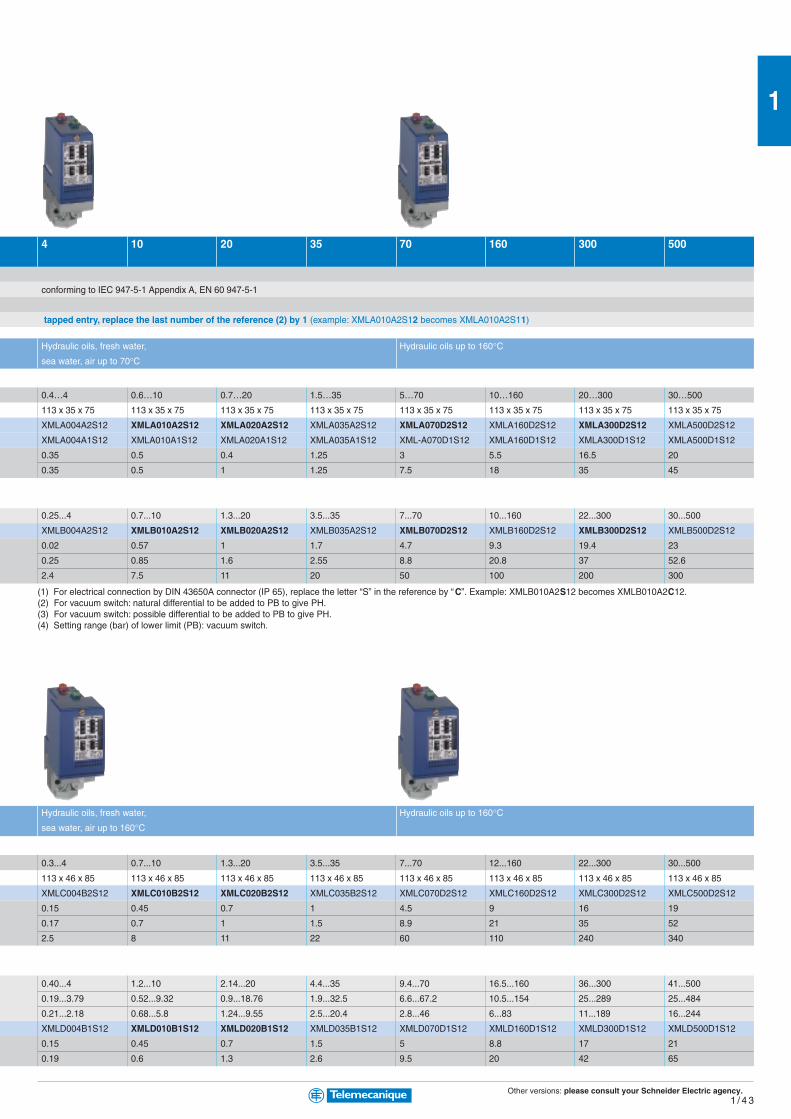
Other versions: please consult your Schneider Electric agency.1 / 4 3
1
4 10 20 35 70 160 300 500
conforming to IEC 947-5-1 Appendix A, EN 60 947-5-1
tapped entry, replace the last number of the reference (2) by 1 (example: XMLA010A2S12 becomes XMLA010A2S11)
Hydraulic oils, fresh water, Hydraulic oils up to 160°Csea water, air up to 70°C
0.4…4 0.6…10 0.7…20 1.5…35 5…70 10…160 20…300 30…500
113 x 35 x 75 113 x 35 x 75 113 x 35 x 75 113 x 35 x 75 113 x 35 x 75 113 x 35 x 75 113 x 35 x 75 113 x 35 x 75
XMLA004A2S12 XMLA010A2S12 XMLA020A2S12 XMLA035A2S12 XMLA070D2S12 XMLA160D2S12 XMLA300D2S12 XMLA500D2S12
XMLA004A1S12 XMLA010A1S12 XMLA020A1S12 XMLA035A1S12 XML-A070D1S12 XMLA160D1S12 XMLA300D1S12 XMLA500D1S12
0.35 0.5 0.4 1.25 3 5.5 16.5 20
0.35 0.5 1 1.25 7.5 18 35 45
0.25...4 0.7...10 1.3...20 3.5...35 7...70 10...160 22...300 30...500
XMLB004A2S12 XMLB010A2S12 XMLB020A2S12 XMLB035A2S12 XMLB070D2S12 XMLB160D2S12 XMLB300D2S12 XMLB500D2S12
0.02 0.57 1 1.7 4.7 9.3 19.4 23
0.25 0.85 1.6 2.55 8.8 20.8 37 52.6
2.4 7.5 11 20 50 100 200 300
(1) For electrical connection by DIN 43650A connector (IP 65), replace the letter “S” in the reference by “C”. Example: XMLB010A2S12 becomes XMLB010A2C12.(2) For vacuum switch: natural differential to be added to PB to give PH.(3) For vacuum switch: possible differential to be added to PB to give PH.(4) Setting range (bar) of lower limit (PB): vacuum switch.
Hydraulic oils, fresh water, Hydraulic oils up to 160°Csea water, air up to 160°C
0.3...4 0.7...10 1.3...20 3.5...35 7...70 12...160 22...300 30...500
113 x 46 x 85 113 x 46 x 85 113 x 46 x 85 113 x 46 x 85 113 x 46 x 85 113 x 46 x 85 113 x 46 x 85 113 x 46 x 85
XMLC004B2S12 XMLC010B2S12 XMLC020B2S12 XMLC035B2S12 XMLC070D2S12 XMLC160D2S12 XMLC300D2S12 XMLC500D2S12
0.15 0.45 0.7 1 4.5 9 16 19
0.17 0.7 1 1.5 8.9 21 35 52
2.5 8 11 22 60 110 240 340
0.40...4 1.2...10 2.14...20 4.4...35 9.4...70 16.5...160 36...300 41...500
0.19...3.79 0.52...9.32 0.9...18.76 1.9...32.5 6.6...67.2 10.5...154 25...289 25...484
0.21...2.18 0.68...5.8 1.24...9.55 2.5...20.4 2.8...46 6...83 11...189 16...244
XMLD004B1S12 XMLD010B1S12 XMLD020B1S12 XMLD035B1S12 XMLD070D1S12 XMLD160D1S12 XMLD300D1S12 XMLD500D1S12
0.15 0.45 0.7 1.5 5 8.8 17 21
0.19 0.6 1.3 2.6 9.5 20 42 65
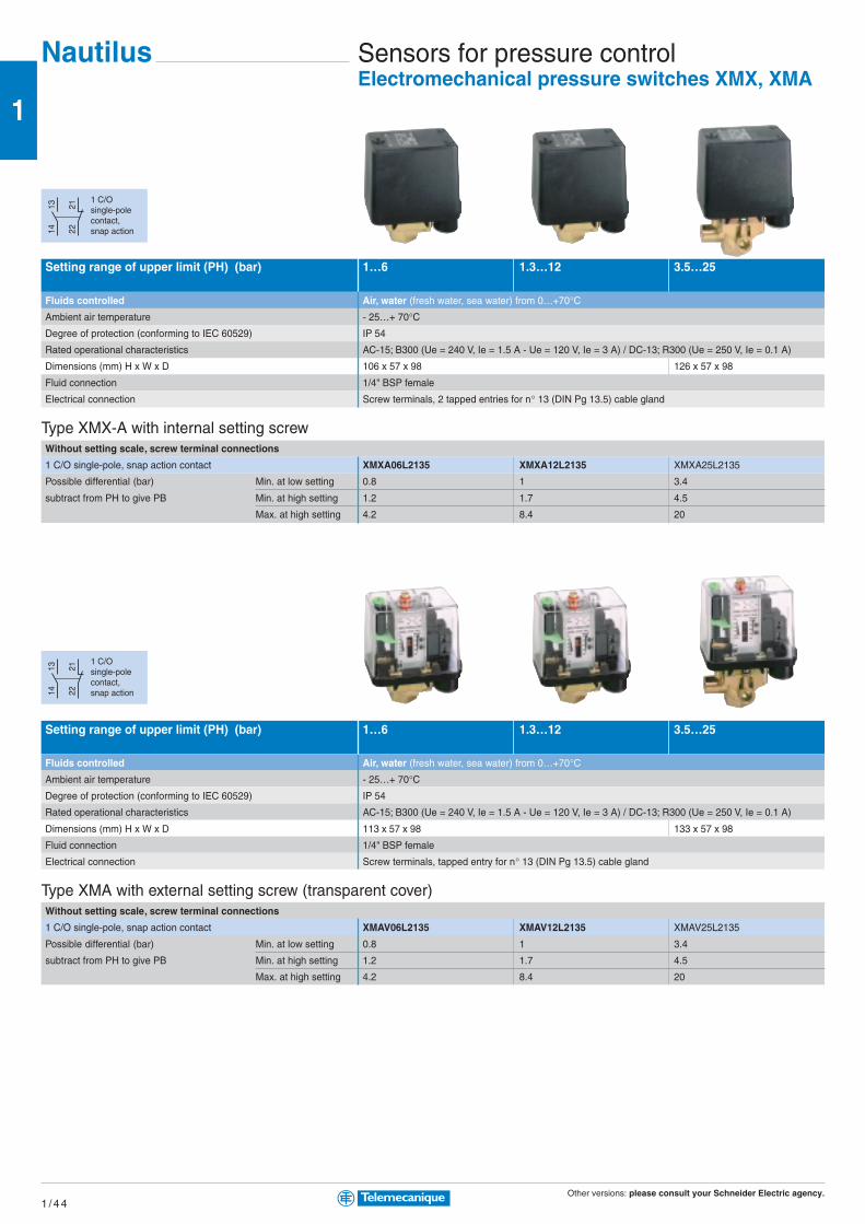
Other versions: please consult your Schneider Electric agency.1 / 4 4
1
222113
14
222113
14Sensors for pressure controlElectromechanical pressure switches XMX, XMA
1 C/Osingle-polecontact,snap action
Setting range of upper limit (PH) (bar) 1…6 1.3…12 3.5…25
Fluids controlled Air, water (fresh water, sea water) from 0…+70°CAmbient air temperature - 25…+ 70°CDegree of protection (conforming to IEC 60529) IP 54
Rated operational characteristics AC-15; B300 (Ue = 240 V, Ie = 1.5 A - Ue = 120 V, Ie = 3 A) / DC-13; R300 (Ue = 250 V, Ie = 0.1 A)
Dimensions (mm) H x W x D 106 x 57 x 98 126 x 57 x 98
Fluid connection 1/4" BSP female
Electrical connection Screw terminals, 2 tapped entries for n° 13 (DIN Pg 13.5) cable gland
Type XMX-A with internal setting screwWithout setting scale, screw terminal connections
1 C/O single-pole, snap action contact XMXA06L2135 XMXA12L2135 XMXA25L2135
Possible differential (bar) Min. at low setting 0.8 1 3.4
subtract from PH to give PB Min. at high setting 1.2 1.7 4.5
Max. at high setting 4.2 8.4 20
Setting range of upper limit (PH) (bar) 1…6 1.3…12 3.5…25
Fluids controlled Air, water (fresh water, sea water) from 0…+70°CAmbient air temperature - 25…+ 70°CDegree of protection (conforming to IEC 60529) IP 54
Rated operational characteristics AC-15; B300 (Ue = 240 V, Ie = 1.5 A - Ue = 120 V, Ie = 3 A) / DC-13; R300 (Ue = 250 V, Ie = 0.1 A)
Dimensions (mm) H x W x D 113 x 57 x 98 133 x 57 x 98
Fluid connection 1/4" BSP female
Electrical connection Screw terminals, tapped entry for n° 13 (DIN Pg 13.5) cable gland
Type XMA with external setting screw (transparent cover)Without setting scale, screw terminal connections
1 C/O single-pole, snap action contact XMAV06L2135 XMAV12L2135 XMAV25L2135
Possible differential (bar) Min. at low setting 0.8 1 3.4
subtract from PH to give PB Min. at high setting 1.2 1.7 4.5
Max. at high setting 4.2 8.4 20
1 C/Osingle-polecontact,snap action
Nautilus

Other versions: please consult your Schneider Electric agency.1 / 4 5
13
4
12
34
12
56
34
12
Sensors for pressure controlElectromechanical pressure switchesfor power circuits, adjustable differentialfor regulation between 2 thresholds
Degree of protection IP 20 IP 65Size (bar) 4.6 7 10.5 4.6 7 10.5Setting range of upper limit (PH) (bar) 1.4…4.6 2.8…7 5.6…10.5 1.4…4.6 2.8…7 5.6…10.5
Fluids controlled Water (fresh water, sea water) from 0…+55°CElectrical connection Screw terminals, 2 cable entries with grommet Screw terminals, 2 tapped entries
for n° 13 (DIN Pg 13.5) cable gland
Ambient air temperature For operation: 0…+ 50°C. For storage: - 30…+ 80°CRated operational characteristics Ie = 10 A, Ue = 250 V AC
Power rating 110 V AC 2-pole, single-phase 0.75 kW (1 HP) 0.75 kW (1 HP)
of controlled AC 2-pole, 3-phase 1.1 kW (1.5 HP) 1.1 kW (1.5 HP)
motors 230 / 400 V AC 2-pole, single-phase 1.5 kW (2 HP) 1.5 kW (2 HP)
AC 2-pole, 3-phase 2.2 kW (3 HP) 2.2 kW (3 HP)
Dimensions (mm) H x W x D 96/105 x 72 x 102 94 x 72 x 102 115 x 72 x 106 115 x 72 x 106
Fluid connection G 1/4 (BSP female) FSG2 FYG22 FYG32 FSG2NE FYG22NE FYG32NE
R 1/4 (BSP male) FSG9 FYG29 FYG39 – – –
G 3/8 (BSP female) rotating nut – – – FSG2NEG – –
Possible differential (bar) At low setting 1 min. - 2.1 max. 1.2 min. - 2.3 max. 1.9 min. - 3 max. 1 min. - 2.1 max. 1.2 min. - 2.3 max. 1.9 min. - 3 max.
subtract from PH to give PB At middle setting 1.1 min. - 2.2 max. 1.4 min. - 2.5 max. 2.1 min. - 3.2 max. 1.1 min. - 2.2 max. 1.4 min. - 2.5 max. 2.1 min. - 3.2 max.
At high setting 1.2 min. - 2.3 max. 1.6 min. - 2.7 max. 2.3 min. - 3.4 max. 1.2 min. - 2.3 max. 1.6 min. - 2.7 max. 2.3 min. - 3.4 max.
Size (bar) 6 12 25
Setting range of upper limit (PH) (bar) 1…6 1.3…12 3.5…25
Fluids controlled Air, water (fresh water, sea water) from 0…+70°CAmbient air temperature For operation: - 25…+ 70°C. For storage: - 40…+ 70°CDecompression valve / On/Off knob without with without with without
Fluid connection G 1/4 (BSP female) 4xG 1/4 (BSP female) G 1/4 (BSP female) 4xG 1/4 (BSP female) G 1/4 (BSP female)
Electrical connection Screw terminals, 2 tapped entries for n° 13 (DIN Pg 13.5) cable gland
Degree of protection IP 54 IP 54 IP 54
Rated insulation voltage Ui = 500 V
Electrical Power 1.5 kW 400 V AC 3-phase: 1 000 000 operating cycles
durability 230 V AC 3-phase: 600 000 operating cycles
2.2 kW 400 V AC 3-phase: 700 000 operating cycles
3 kW 400 V AC 3-phase: 500 000 operating cycles
Dimensions (mm) H x W x D 106 x 57 x 97.5 138 x 57 x 97.5 106 x 57 x 97.5 138 x 57 x 97.5 126 x 57 x 97.5
Type of contacts 2 N/C 2-pole, snap action contact XMPA06B2131 XMPE06B2431 XMPA12B2131 XMPE12B2431 XMPA25B2131
3 N/C 3-pole, snap action contact XMPA06C2131 XMPE06C2431 XMPA12B2131 XMPE12C2431 XMPA25B2131
Possible differential (bar) Min. at low setting 0.8 0.8 1 1 3.4
subtract from PH to give PB Min. at high setting 1.2 1.2 1.7 1.7 4.5
Max. at high setting 4.2 4.2 8.4 8.4 20
Nautilus
2 N/C 2-polecontact, snap action
2 N/C 2-polecontact, snap action
3 N/C 3-polecontact, snap action
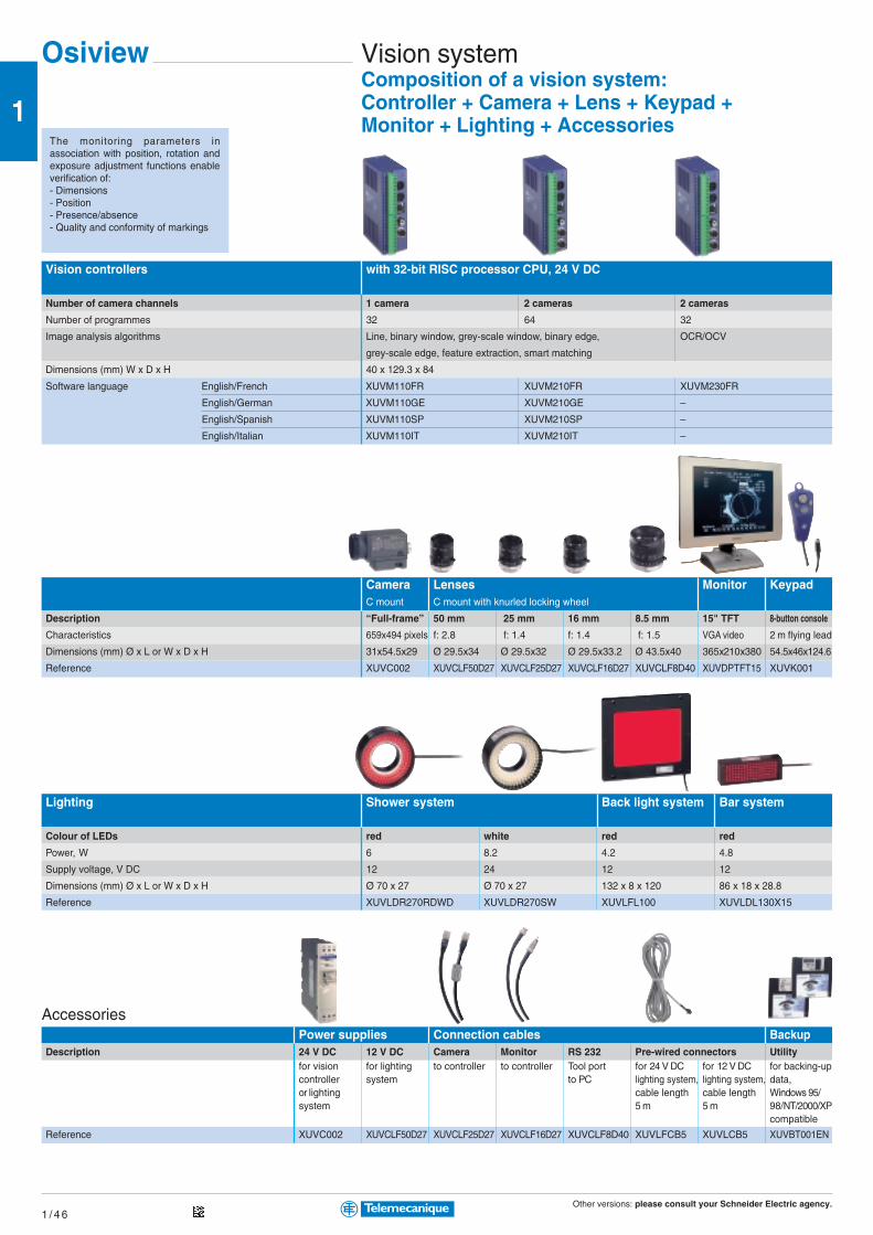
Other versions: please consult your Schneider Electric agency.1 / 4 6
1
Osiview Vision systemComposition of a vision system:Controller + Camera + Lens + Keypad +Monitor + Lighting + Accessories
Vision controllers with 32-bit RISC processor CPU, 24 V DC
Number of camera channels 1 camera 2 cameras 2 cameras
Number of programmes 32 64 32
Image analysis algorithms Line, binary window, grey-scale window, binary edge, OCR/OCV
grey-scale edge, feature extraction, smart matching
Dimensions (mm) W x D x H 40 x 129.3 x 84
Software language English/French XUVM110FR XUVM210FR XUVM230FR
English/German XUVM110GE XUVM210GE –
English/Spanish XUVM110SP XUVM210SP –
English/Italian XUVM110IT XUVM210IT –
Camera Lenses Monitor KeypadC mount C mount with knurled locking wheel
Description “Full-frame” 50 mm 25 mm 16 mm 8.5 mm 15" TFT 8-button console
Characteristics 659x494 pixels f: 2.8 f: 1.4 f: 1.4 f: 1.5 VGA video 2 m flying lead
Dimensions (mm) Ø x L or W x D x H 31x54.5x29 Ø 29.5x34 Ø 29.5x32 Ø 29.5x33.2 Ø 43.5x40 365x210x380 54.5x46x124.6
Reference XUVC002 XUVCLF50D27 XUVCLF25D27 XUVCLF16D27 XUVCLF8D40 XUVDPTFT15 XUVK001
Lighting Shower system Back light system Bar system
Colour of LEDs red white red red
Power, W 6 8.2 4.2 4.8
Supply voltage, V DC 12 24 12 12
Dimensions (mm) Ø x L or W x D x H Ø 70 x 27 Ø 70 x 27 132 x 8 x 120 86 x 18 x 28.8
Reference XUVLDR270RDWD XUVLDR270SW XUVLFL100 XUVLDL130X15
AccessoriesPower supplies Connection cables Backup
Description 24 V DC 12 V DC Camera Monitor RS 232 Pre-wired connectors Utilityfor vision for lighting to controller to controller Tool port for 24 V DC for 12 V DC for backing-upcontroller system to PC lighting system, lighting system, data,or lighting cable length cable length Windows 95/system 5 m 5 m 98/NT/2000/XP
compatible
Reference XUVC002 XUVCLF50D27 XUVCLF25D27 XUVCLF16D27 XUVCLF8D40 XUVLFCB5 XUVLCB5 XUVBT001EN
The monitoring parameters inassociation with position, rotation andexposure adjustment functions enableverification of:- Dimensions- Position- Presence/absence- Quality and conformity of markings
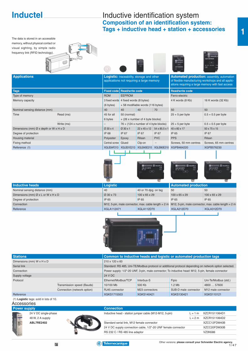
Other versions: please consult your Schneider Electric agency.1 / 4 7
1DATA DATA
DATA DATA
DATA DATA
DATA DATA
DATA DATA
DATA DATA
DATA DATA
DATA DATA
Inductel Inductive identification systemComposition of an identification system:Tags + inductive head + station + accessories
Applications Logistic: traceability, storage and other Automated production: assembly, automationapplications not requiring a large memory of flexible manufacturing workshops and all applic-
ations requiring a large memory with fast access
Tags Fixed code Read/write code Read/write code
Type of memory ROM EEPROM Ferro-electric
Memory capacity 3 fixed words 4 fixed words (8 bytes) 4 K words (8 Kb) 16 K words (32 Kb)
(6 bytes) + 58 modifiable words (116 bytes)
Nominal sensing distance (mm) 40 40 40 70 50 50
Time Read (ms) 45 for all 50 (normal) 25 + 5 per byte 0.5 + 0.5 per byte
6 bytes + (26 x number of 4 byte blocks)
Write (ms) – 76 + (124 x number of 4 byte blocks) 25 + 5 per byte 0.5 + 0.5 per byte
Dimensions (mm) Ø x depth or W x H x D Ø 30 x 4 Ø 30 x 1 22 x 45 x 12 54 x 85.5 x 1 40 x 60 x 17 50 x 75 x 15
Degree of protection IP 68 IP 67 IP 67 IP 67 IP 65 IP 67
Housing material Polyester Epoxy Rilsan PVC PPS Rilsan
Fixing method Central screw Glued Clip-on – Screws, 50 mm centres Screws, 65 mm centres
Reference (1) XGLB34F213 XGLB31E213 XGLB45E215 XGLB90E210 XGPB464220 XGPB576230
Inductive heads Logistic Automated productionNominal sensing distance (mm) 40 40 or 70 dpg. on tag 50 50
Dimensions (mm) Ø x L or W x H x D Ø 30 x 73 100 x 65 x 29 100 x 65 x 29 100 x 65 x 29
Degree of protection IP 65 IP 65 IP 65 IP 65
Connection M12, 5-pin, male connector, max. cable length = 2 m M12, 5-pin, male connector, max. cable length = 2 m
Reference XGLA112A71 XGLA112D70 XGLA212D70 XGLA312D70
Stations Common to inductive heads and logistic or automated production tagsDimensions (mm) W x H x D 210 x 120 x 60
Serial link Standard: RS 485, Uni-TE/Modbus protocol or additional protocol depending on network option selected.
Connection Power supply: 1/2"-20 UNF, 3-pin, male connector; To inductive head: M12, 5-pin, female connector
Supply voltage 24 V DC
Protocol Ethernet/Modbus/TCP Interbus-S Fipio Uni-Te/Modbus (std.)
Transmission speed (Bauds) 10/100 Mb 500 Kb 1.2 Mb 4800 … 57600
Connection (network option) RJ45 connector M23 connectors SUB-D male connector M12 male connector
Reference XGKS1715503 XGKS140421 XGKS130421 XGKS110121
(1) Logistic tags: sold in lots of 10.
Inductive head - station jumper cable (M12-M12, 5-pin) L = 1 m XZCR1511064D1
L = 2 m XZCR1511064D2
Standard serial link, M12 female connector XZCC12FDM40B
24 V DC supply connection cable, 1/2"-20 UNF female connector XZCC20FDM30B
RS 232 C / RS 485 line adaptor VZ3N586
24 V DC single-phase
48 W, 2 A supply
ABL7RE2402
AccessoriesPower supply Connection
The data is stored in an accessible
memory, without physical contact or
visual sighting, by simple radio
frequency link (RFID technology).
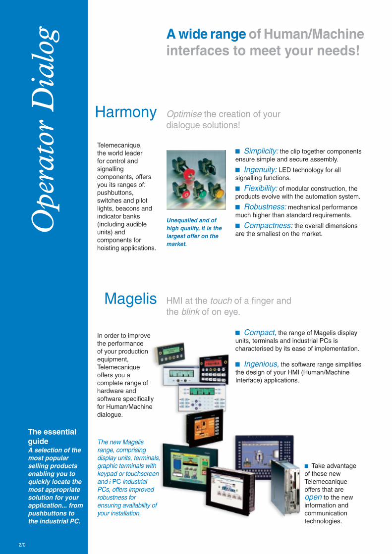
Ope
rato
r D
ialo
g
Optimise the creation of yourdialogue solutions!
The essentialguideA selection of themost popularselling productsenabling you toquickly locate themost appropriatesolution for yourapplication... frompushbuttons tothe industrial PC.
A wide range of Human/Machineinterfaces to meet your needs!
Harmony
Telemecanique,the world leaderfor control andsignallingcomponents, offersyou its ranges of:pushbuttons,switches and pilotlights, beacons andindicator banks(including audibleunits) andcomponents forhoisting applications.
In order to improvethe performanceof your productionequipment,Telemecaniqueoffers you acomplete range ofhardware andsoftware specificallyfor Human/Machinedialogue.
b Compact, the range of Magelis displayunits, terminals and industrial PCs ischaracterised by its ease of implementation.
b Ingenious, the software range simplifiesthe design of your HMI (Human/MachineInterface) applications.
b Take advantageof these newTelemecaniqueoffers that areopen to the newinformation andcommunicationtechnologies.
The new Magelisrange, comprisingdisplay units, terminals,graphic terminals withkeypad or touchscreenand i PC industrialPCs, offers improvedrobustness forensuring availability ofyour installation.
HMI at the touch of a finger andthe blink of on eye.
Magelis
b Simplicity: the clip together componentsensure simple and secure assembly.
b Ingenuity: LED technology for allsignalling functions.
b Flexibility: of modular construction, theproducts evolve with the automation system.
b Robustness: mechanical performancemuch higher than standard requirements.
b Compactness: the overall dimensionsare the smallest on the market.
Unequalled and ofhigh quality, it is thelargest offer on themarket.
2/0

To benefit fromperfectinteroperabilityselectTelemecaniquesoftware.
b XBTL1001/L1003b Vijeo Designerb Vijeo Lookb Monitor Prob The FactoryCastHMI Web server
2/1
2
Contents
Control and signalling units
b Pushbuttons, switches and pilot lights Ø 16with plastic bezel, Harmony XB6 ........................................ 2/2 to 2/4b LED pilot lights Ø 8 and 12Harmony XVL ................................................................................ 2/5b Pushbuttons, switches and pilot lights Ø 22with metal bezel, Harmony XB4 .......................................... 2/6 to 2/9b Pushbuttons, switches and pilot lights Ø 22with plastic bezel, Harmony XB5 .................................... 2/10 to 2/12b Control stationsHarmony XAL ............................................................................. 2/13b Monolithic pushbuttons, switches and pilotlights Ø 22 with plastic bezel, Harmony XB7 .................. 2/14 to 2/15b Pushbuttons, switches and pilot lights Ø 30with metal or plastic bezel, Harmony 9001 ..................... 2/16 to 2/19b Cam switchesHarmony Series K .......................................................... 2/20 to 2/21b Beacons and indicator banks “Universal”Harmony XVB / XVP ................................................................... 2/22b Beacons and indicator banks “Optimum”Harmony XVM / XVDLS / XVE .................................................... 2/23b Beacons and indicator banks “Application”Harmony XVD / XVR / XVS ......................................................... 2/24b Beacons and indicator banks accessoriesHarmony XV ................................................................................ 2/25b Pendant control stationsXAC .................................................................................. 2/26 to 2/27
b Control and signalling units for explosive atmospheres(see Chapter 10 “Explosive Atmospheres”)
Human/Machine Interfaces
b Display unitsMagelis XBTN and XBTHM ........................................................ 2/28b TerminalsMagelis XBTR, XBTPM, XBTF and XBTG .................... 2/29 to 2/32b Industrial PCsMagelis Smart i PC, Compact i PC, Modular i PC ....... 2/33 to 2/35b SoftwareXBTL, Vijeo Designer, Vijeo Look, Monitor Pro ............ 2/36 to 2/38b Embedded Web servers and gatewaysFactoryCast ................................................................................ 2/39

Other versions: please consult your Schneider Electric agency.
2
2/2
= + +
= +
Illuminated pushbuttons
Type of head Flush push
Shape of head rectangular (2)
Degree of protection IP 65 / Nema 4, 4X, 13 / Class II
Mounting (mm) panel cut-out Ø 16.2
mounting centres 24 x 18 with rectangular head, 18 x 18 with square or circular head
Dimensions (mm) W x H x D (below head) 24 x 18 x 50 with rectangular head, 18 x 18 x 50 with square or circular head
Connection (3) Tags for 2.8 x 0.5 Faston connectors or for soldering
Type of push Spring return
Complete products Products for user assembly
12 … 24 V AC/DC
References white N/O XB6 DW1B1B ZB6 Ep1B (1) ZB6 Z1B ZB6 DW1
N/C + N/O XB6 DW1B5B ZB6 Ep1B (1) ZB6 Z5B ZB6 DW1
green N/O XB6 DW3B1B ZB6 Ep3B (1) ZB6 Z1B ZB6 DW3
N/C + N/O XB6 DW3B5B ZB6 Ep3B (1) ZB6 Z5B ZB6 DW3
red N/C XB6 DW4B2B ZB6 Ep4B (1) ZB6 Z2B ZB6 DW4
N/C + N/O XB6 DW4B5B ZB6 Ep4B (1) ZB6 Z5B ZB6 DW4
yellow N/O – ZB6 Ep5B (1) ZB6 Z1B ZB6 DW5
N/C + N/O XB6 DW5B5B ZB6 Ep5B (1) ZB6 Z5B ZB6 DW5
Type of push Latching
References white N/O – ZB6 Ep1B (1) ZB6 Z1B ZB6 DF1
N/C + N/O XB6 DF1B5B ZB6 Ep1B (1) ZB6 Z5B ZB6 DF1
green N/O XB6 DF3B1B ZB6 Ep3B (1) ZB6 Z1B ZB6 DF3
N/C + N/O XB6 DF3B5B ZB6 Ep3B (1) ZB6 Z5B ZB6 DF3
red N/C XB6 DF4B2B ZB6 Ep4B (1) ZB6 Z2B ZB6 DF4
N/C + N/O XB6 DF4B5B ZB6 Ep4B (1) ZB6 Z5B ZB6 DF4
yellow N/O – ZB6 Ep5B (1) ZB6 Z1B ZB6 DF5
N/C + N/O – ZB6 Ep5B (1) ZB6 Z5B ZB6 DF5
Pilot lights
Type of head Smooth lens cap
Shape of head rectangular (2)
Complete products Products for user assembly
12 … 24 V AC/DC
References white XB6 DV1BB ZB6 Ep1B (1) ZB6 DV1
green XB6 DV3BB ZB6 Ep3B (1) ZB6 DV3
red XB6 DV4BB ZB6 Ep4B (1) ZB6 DV4
yellow XB6 DV5BB ZB6 Ep5B (1) ZB6 DV5
blue – ZB6 Ep6B (1) ZB6 DV6
(1) Basic reference, to be completed by the letter B, G or M indicating the required voltage. See voltage table above.
(2) For products with a square head, replace the letter D in the reference by the letter C (XB6 DW1B1B becomes XB6 CW1B1B).
For products with a circular head, replace the letter D in the reference by the letter A (XB6 DW1B1B becomes XB6 AW1B1B).
(3) Alternative connection: 1 x 0.5 pins for printed circuit boards.
Pushbuttons, switches and pilot lights Ø 16with plastic bezelContact functions and light functionswith integral LED
(1):
Voltage Letter (p)
12…24 V AC/DC (15 mA) B
48…120 V AC (25 mA) G
230…240 V AC (25 mA) M
+ 0.20
HarmonyXB6
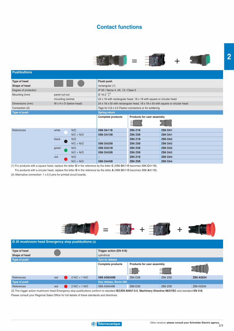
Other versions: please consult your Schneider Electric agency.
2
2/3
= +
= + +
Pushbuttons
Type of head Flush push
Shape of head rectangular (1)
Degree of protection IP 65 / Nema 4, 4X, 13 / Class II
Mounting (mm) panel cut-out Ø 16.2
mounting centres 24 x 18 with rectangular head, 18 x 18 with square or circular head
Dimensions (mm) W x H x D (below head) 24 x 18 x 50 with rectangular head, 18 x 18 x 50 with square or circular head
Connection (2) Tags for 2.8 x 0.5 Faston connectors or for soldering
Type of push Spring return
Complete products Products for user assembly
References white N/O XB6 DA11B ZB6 Z1B ZB6 DA1
N/C + N/O XB6 DA15B ZB6 Z5B ZB6 DA1
black N/O – ZB6 Z1B ZB6 DA2
N/C + N/O XB6 DA25B ZB6 Z5B ZB6 DA2
green N/O XB6 DA31B ZB6 Z2B ZB6 DA3
N/C + N/O XB6 DA35B ZB6 Z5B ZB6 DA3
red N/O – ZB6 Z1B ZB6 DA4
N/C + N/O XB6 DA45B ZB6 Z5B ZB6 DA4
(1) For products with a square head, replace the letter D in the reference by the letter C (XB6 DA11B becomes XB6 CA11B).
For products with a circular head, replace the letter D in the reference by the letter A (XB6 DA11B becomes XB6 AA11B).
(2) Alternative connection: 1 x 0.5 pins for printed circuit boards.
Ø 30 mushroom head Emergency stop pushbuttons (3)
Type of head Trigger action (EN 418)
Shape of head cylindrical
Type of push Turn to release
Complete products Products for user assembly
References red 2 N/C + 1 N/O XB6 AS8349B ZB6 E2B ZB6 Z5B ZB6 AS834
Type of push Key release, Ronis 200
References red 2 N/C + 1 N/O XB6 AS9349B ZB6 E2B ZB6 Z5B ZB6 AS934
(3) The trigger action mushroom head Emergency stop pushbuttons conform to standard IEC/EN 60947-5-5, Machinery Directive 98/37/EC and standard EN 418.
Please consult your Regional Sales Office for full details of these standards and directives.
+ 0.20
Contact functions

Other versions: please consult your Schneider Electric agency.
2
2/4
= +
= +
= + +
Selector switches and key switches
Type of head Black handle
Shape of head rectangular (2)
Degree of protection IP 65 / Nema 4, 4X, 13 / Class II (except key switches)
Mounting (mm) panel cut-out Ø 16.2
mounting centres 24 x 18 with rectangular head, 18 x 18 with square or circular head
Dimensions (mm) W x H x D (below head) 24 x 18 x 50 with rectangular head, 18 x 18 x 50 with square or circular head
Connection (3) Tags for 2.8 x 0.5 Faston connectors or for soldering
Type of operator Black handle
Complete products Products for user assembly
Number and type of positions 2 positions 2 positions 2 positions
stay put stay put spring return to centre
References N/O XB6 DD221B ZB6 Z1B ZB6 DD22 ZB6 Z1B ZB6 DD24
N/C + N/O XB6 DD225B ZB6 Z5B ZB6 DD22 ZB6 Z5B ZB6 DD24
Number and type of positions 3 positions 3 positions 3 positions
stay put stay put spring return to centre
References N/O XB6 DD235B ZB6 Z5B ZB6 DD23 ZB6 Z5B ZB6 DD25
Type of operator Ronis key, n° 200
Complete products Products for user assembly
Number and type of positions 2 positions 2 positions 2 positions
stay put stay put spring return to centre
References N/C + N/O XB6 DGC5B ZB6 Z5B ZB6 DGC ZB6 Z5B ZB6 DGB
Number and type of positions 3 positions 3 positions 3 positions
stay put stay put spring return to centre
References N/C + N/O XB6 DGH5B ZB6 Z5B ZB6 DGH ZB6 Z5B ZB6 DGS
Illuminated selector switches
Type of operator Coloured handle
Products for user assembly
Number and type of positions 2 positions 3 positions
stay put stay put
References white N/C + N/O ZB6 Ep1B (1) ZB6 Z5B ZB6 DD02 ZB6 DD03 ZB6 YK1
green N/C + N/O ZB6 Ep3B (1) ZB6 Z5B ZB6 DD02 ZB6 DD03 ZB6 YK3
red N/C + N/O ZB6 Ep4B (1) ZB6 Z5B ZB6 DD02 ZB6 DD03 ZB6 YK4
(1) Basic reference, to be completed by the letter B, G or M indicating the required voltage. See voltage table above.
(2) For products with a square head, replace the letter D in the reference by the letter C (XB6 DD221B becomes XB6 CD221B).
For products with a circular head, replace the letter D in the reference by the letter A (XB6 DD221B becomes XB6 AD221B).
(3) Alternative connection: 1 x 0.5 pins for printed circuit boards.
(1):
Voltage Letter (p)
12…24 V AC/DC (15 mA) B
48…120 V AC (25 mA) G
230…240 V AC (25 mA) M
+ 0.20
HarmonyXB6
60° 45°60°
60° 45°60°60° 45°60°
70° 45°70°
70° 45°70°70° 45°70°
60° 60° 60°
Pushbuttons, switches and pilot lights Ø 16with plastic bezelContact functions and light functionswith integral LED
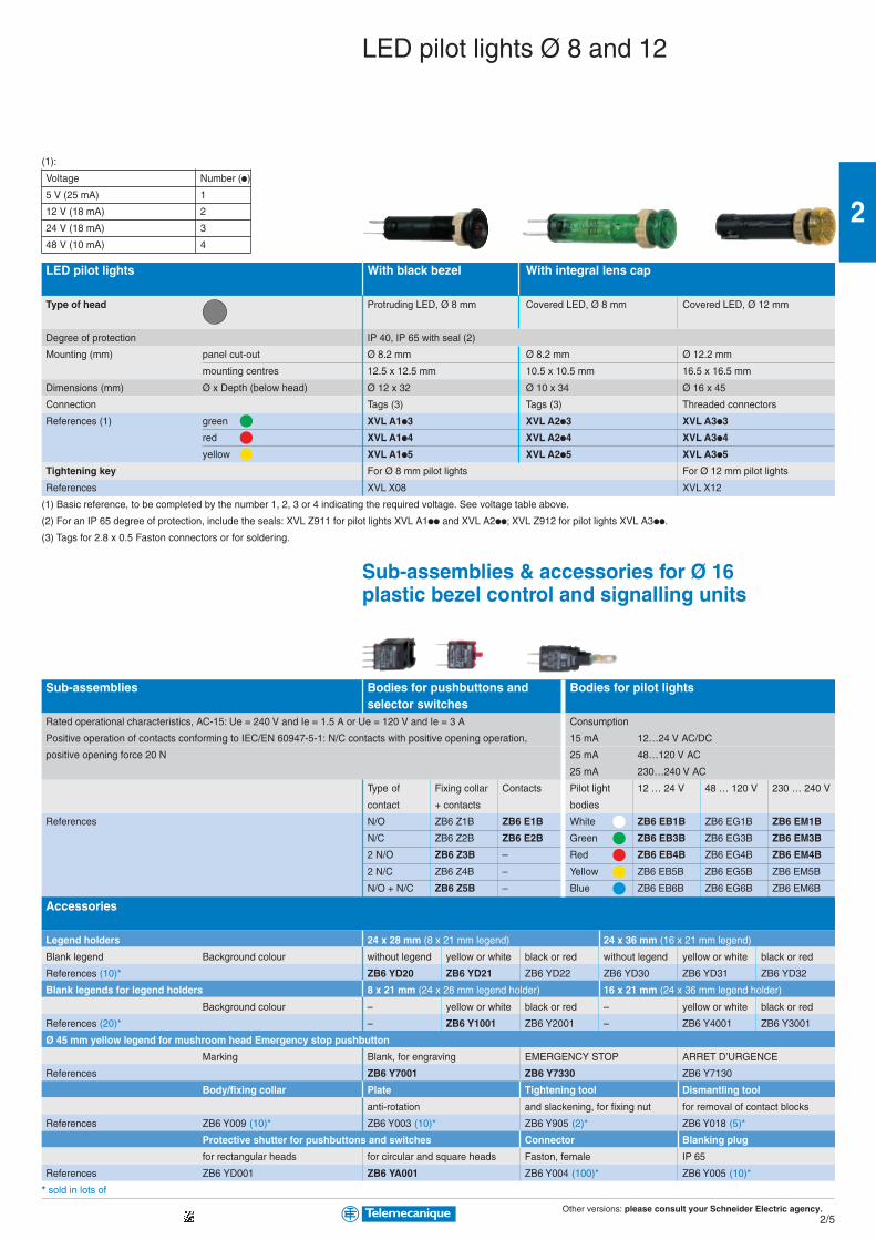
Other versions: please consult your Schneider Electric agency.
2
2/5
LED pilot lights With black bezel With integral lens cap
Type of head Protruding LED, Ø 8 mm Covered LED, Ø 8 mm Covered LED, Ø 12 mm
Degree of protection IP 40, IP 65 with seal (2)
Mounting (mm) panel cut-out Ø 8.2 mm Ø 8.2 mm Ø 12.2 mm
mounting centres 12.5 x 12.5 mm 10.5 x 10.5 mm 16.5 x 16.5 mm
Dimensions (mm) Ø x Depth (below head) Ø 12 x 32 Ø 10 x 34 Ø 16 x 45
Connection Tags (3) Tags (3) Threaded connectors
References (1) green XVL A1p3 XVL A2p3 XVL A3p3
red XVL A1p4 XVL A2p4 XVL A3p4
yellow XVL A1p5 XVL A2p5 XVL A3p5
Tightening key For Ø 8 mm pilot lights For Ø 12 mm pilot lights
References XVL X08 XVL X12
(1) Basic reference, to be completed by the number 1, 2, 3 or 4 indicating the required voltage. See voltage table above.
(2) For an IP 65 degree of protection, include the seals: XVL Z911 for pilot lights XVL A1pp and XVL A2pp; XVL Z912 for pilot lights XVL A3pp.
(3) Tags for 2.8 x 0.5 Faston connectors or for soldering.
Sub-assemblies & accessories for Ø 16plastic bezel control and signalling units
Sub-assemblies Bodies for pushbuttons and Bodies for pilot lightsselector switches
Rated operational characteristics, AC-15: Ue = 240 V and Ie = 1.5 A or Ue = 120 V and Ie = 3 A Consumption
Positive operation of contacts conforming to IEC/EN 60947-5-1: N/C contacts with positive opening operation, 15 mA 12…24 V AC/DC
positive opening force 20 N 25 mA 48…120 V AC
25 mA 230…240 V AC
Type of Fixing collar Contacts Pilot light 12 … 24 V 48 … 120 V 230 … 240 V
contact + contacts bodies
References N/O ZB6 Z1B ZB6 E1B White ZB6 EB1B ZB6 EG1B ZB6 EM1B
N/C ZB6 Z2B ZB6 E2B Green ZB6 EB3B ZB6 EG3B ZB6 EM3B
2 N/O ZB6 Z3B – Red ZB6 EB4B ZB6 EG4B ZB6 EM4B
2 N/C ZB6 Z4B – Yellow ZB6 EB5B ZB6 EG5B ZB6 EM5B
N/O + N/C ZB6 Z5B – Blue ZB6 EB6B ZB6 EG6B ZB6 EM6B
Accessories
Legend holders 24 x 28 mm (8 x 21 mm legend) 24 x 36 mm (16 x 21 mm legend)
Blank legend Background colour without legend yellow or white black or red without legend yellow or white black or red
References (10)* ZB6 YD20 ZB6 YD21 ZB6 YD22 ZB6 YD30 ZB6 YD31 ZB6 YD32
Blank legends for legend holders 8 x 21 mm (24 x 28 mm legend holder) 16 x 21 mm (24 x 36 mm legend holder)
Background colour – yellow or white black or red – yellow or white black or red
References (20)* – ZB6 Y1001 ZB6 Y2001 – ZB6 Y4001 ZB6 Y3001
Ø 45 mm yellow legend for mushroom head Emergency stop pushbutton
Marking Blank, for engraving EMERGENCY STOP ARRET D’URGENCE
References ZB6 Y7001 ZB6 Y7330 ZB6 Y7130
Body/fixing collar Plate Tightening tool Dismantling tool
anti-rotation and slackening, for fixing nut for removal of contact blocks
References ZB6 Y009 (10)* ZB6 Y003 (10)* ZB6 Y905 (2)* ZB6 Y018 (5)*
Protective shutter for pushbuttons and switches Connector Blanking plug
for rectangular heads for circular and square heads Faston, female IP 65
References ZB6 YD001 ZB6 YA001 ZB6 Y004 (100)* ZB6 Y005 (10)*
* sold in lots of
LED pilot lights Ø 8 and 12
(1):
Voltage Number (p)
5 V (25 mA) 1
12 V (18 mA) 2
24 V (18 mA) 3
48 V (10 mA) 4
Other versions: please consult your Schneider Electric agency.
2
2/6
= +
= +
Pushbuttons, spring return
Type of head Chromium plated circular bezel
Degree of protection IP 65 / Nema 4X, 13 / Class I. (IP 66 for booted pushbuttons)
Mounting (mm) panel cut-out Ø 22.5 (22.4 recommended)
mounting centres 30 (horizontal) x 40 (vertical)
Depth (mm) below head 43
Connection (1) Screw clamp terminals
Type of push Flush Flush, booted
Unmarked Products Complete For user assembly Complete For user assembly
References black N/O XB4 BA21 ZB4 BZ101 ZB4 BA2 XB4 BP21 ZB4 BZ101 ZB4 BP2
green N/O XB4 BA31 ZB4 BZ101 ZB4 BA3 XB4 BP31 ZB4 BZ101 ZB4 BP3
red N/C XB4 BA42 ZB4 BZ102 ZB4 BA4 XB4 BP42 ZB4 BZ102 ZB4 BP4
yellow N/O XB4 BA51 ZB4 BZ101 ZB4 BA5 XB4 BP51 ZB4 BZ101 ZB4 BP5
blue N/O XB4 BA61 ZB4 BZ101 ZB4 BA6 XB4 BP61 ZB4 BZ101 ZB4 BP6
Type of push Flush
With international marking Products Complete For user assembly
References green N/O XB4 BA3311 ZB4 BZ101 ZB4 BA331 – – –
red N/C XB4 BA4322 ZB4 BZ102 ZB4 BA432 – – –
white N/O XB4 BA3341 ZB4 BZ101 ZB4 BA334 – – –
black N/O XB4 BA3351 ZB4 BZ101 ZB4 BA335 _ _ _
Type of push Projecting Mushroom head, Ø 40 mm
Unmarked Products Complete For user assembly Complete For user assembly
References black N/O – – – XB4 BC21 ZB4 BZ101 ZB4 BC2
red N/C XB4 BL42 ZB4 BZ102 ZB4 BL4 – – –
Type of push Double-headed pushbuttons Double-headed pushbuttons, booted
Degree of protection IP 40 IP 66
With international marking Products Complete For user assembly Complete For user assembly
References green / N/C + N/O XB4 BL845 ZB4 BZ105 ZB4 BL8434 XB4 BL945 ZB4 BZ105 ZB4 BL9434
red
(1) Alternative connections: plug-in connector, Faston connectors (6.35 and 2 x 2.8).
Ø 40 mm mushroom head Emergency stop pushbuttons (2)
Latching Trigger action (EN 418)Type of push Push-pull (N/C) Push-pull (N/C + N/O)
Unmarked Products Complete For user assembly Complete For user assembly
References red N/C or N/C + N/O XB4 BT42 ZB4 BZ102 ZB4 BT4 XB4 BT845 ZB4 BZ105 ZB4 BT84
Type of push Turn to release (N/C) Turn to release (N/C + N/O)
References red N/C or N/C + N/O XB4 BS542 ZB4 BZ102 ZB4 BS54 XB4 BS8445 ZB4 BZ105 ZB4 BS844
Type of push Key release (N/C) Key release (N/C + N/O)
References red N/C or N/C + N/O XB4 BS142 ZB4 BZ102 ZB4 BS14 XB4 BS9445 ZB4 BZ105 ZB4 BS944
(2) The mushroom head Emergency stop pushbuttons conform to standard IEC/EN 60947-5-5 and Machinery Directive 98/37/EC.Trigger action mushroom head Emergency stop pushbuttons conform to standard EN 418.
HarmonyXB4
+ 0.40
Pushbuttons, switches and pilot lights Ø 22with metal bezelContact functions

Other versions: please consult your Schneider Electric agency.
2
2/7
= +
= +
Selector switches and key switches
Type of head Chromium plated circular bezel
Degree of protection IP 66 / Nema 4X, 13 / Class I
Mounting (mm) panel cut-out Ø 22.5 (22.4 recommended)
mounting centres 30 (horizontal) x 40 (vertical)
Depth (mm) below head 43
Connection (1) Screw clamp terminals
Type of operator Handle
Products Complete For user assembly Complete For user assembly
Number and type of positions 2 positions 2 positions 2 positions 2 positions
stay put stay put spring return to left spring return to left
References black N/O XB4 BD21 ZB4 BZ101 ZB4 BD2 XB4 BD41 ZB4 BZ101 ZB4 BD4
Number and type of positions 3 positions 3 positions 3 positions 3 positions
stay put stay put spring return to centre spring return to centre
References black N/O + N/O XB4 BD33 ZB4 BZ103 ZB4 BD3 XB4 BD53 ZB4 BZ103 ZB4 BD5
Type of operator Key, n° 455
Products Complete For user assembly Complete For user assembly
Number and type of positions (2) 2 positions 2 positions 2 positions 2 positions
stay put stay put stay put stay put
References black N/O XB4 BG21 ZB4 BZ101 ZB4 BG2 XB4 BG41 ZB4 BZ101 ZB4 BG4
Number and type of positions 2 positions 2 positions 3 positions 3 positions
spring return to left spring return to left stay put stay put
References black N/O XB4 BG61 ZB4 BZ101 ZB4 BG6 – – –
black N/O + N/O – – – XB4 BG33 ZB4 BZ103 ZB4 BG3
Separate components
Electrical blocks
Single contact blocks
Rated operational characteristics AC-15, 240 V - 3 A
Positive operation of contacts conforming to IEC/EN 60947-5-1 All functions incorporating a N/C contact are positive opening operation
References (5)* N/O ZBE 101
N/C ZBE 102
(1) Alternative connections: plug-in connector, Faston connectors (6.35 and 2 x 2.8).
(2) The symbol indicates key withdrawal position.
* sold in lots of
+ 0.40
Contact functions

Other versions: please consult your Schneider Electric agency.
2
2/8
= +
= +
HarmonyXB4
+ 0.40
Pilot lights
Type of head Circular bezel
Smooth lens cap
Degree of protection IP 66 / Nema 4X, 13 / Class I
Mounting (mm) panel cut-out Ø 22.5 (22.4 recommended)
mounting centres 30 (horizontal) x 40 (vertical)
Depth below head 43
Connection (1) Screw clamp terminals
Light source Integral LED Direct supply for BA 9s bulb (not included)
Products Complete Complete For user assembly
Supply voltage 24 V AC/DC 48…120 V AC 230…240 V AC 250 V max., 2.4 W max.
References white XB4 BVB1 XB4 BVG1 XB4 BVM1 XB4 BV61 ZB4 BV6 ZB4 BV01
green XB4 BVB3 XB4 BVG3 XB4 BVM3 XB4 BV63 ZB4 BV6 ZB4 BV03
red XB4 BVB4 XB4 BVG4 XB4 BVM4 XB4 BV64 ZB4 BV6 ZB4 BV04
yellow XB4 BVB5 XB4 BVG5 XB4 BVM5 XB4 BV65 ZB4 BV6 ZB4 BV05
blue XB4 BVB6 XB4 BVG6 XB4 BVM6 – – –
Illuminated pushbuttons and selector switches
Type Flush push, spring return, illuminated pushbuttons
Light source Integral LED Direct supply for BA 9s bulb (not included)
Products Complete Complete For user assembly
Supply voltage 24 V AC/DC 48…120 V AC 230…240 V AC 250 V max., 2.4 W max.
References white N/C + N/O XB4 BW31B5 XB4 BW31G5 XB4 BW31M5 XB4 BW3165 ZB4 BW065 ZB4 BW31
green N/C + N/O XB4 BW33B5 XB4 BW33G5 XB4 BW33M5 XB4 BW3365 ZB4 BW065 ZB4 BW33
red N/C + N/O XB4 BW34B5 XB4 BW34G5 XB4 BW34M5 XB4 BW3465 ZB4 BW065 ZB4 BW34
yellow N/C + N/O XB4 BW35B5 XB4 BW35G5 XB4 BW35M5 XB4 BW3565 ZB4 BW065 ZB4 BW35
blue N/C + N/O XB4 BW36B5 XB4 BW36G5 XB4 BW36M5 – – –
Type Double-headed pushbuttons with LED pilot light Illuminated selector switches
(1 flush green push, 1 projecting red push) (2 position stay put)
Degree of protection IP 40 IP 65
Light source Integral LED Integral LED
Products Complete Complete
Supply voltage 24 V AC/DC 48…120 V AC 230…240 V AC 24 V AC/DC 48…120 V AC 230…240 V AC
References green N/C + N/O – – – XB4 BK123B5 XB4 BK123G5 XB4 BK123M5
red N/C + N/O – – – XB4 BK124B5 XB4 BK124G5 XB4 BK124M5
yellow N/C + N/O XB4 BW84B5 XB4 BW84G5 XB4 BW84M5 XB4 BK125B5 XB4 BK125G5 XB4 BK125M5
(1) Alternative connections: plug-in connector, Faston connectors (6.35 and 2 x 2.8).
Pushbuttons, switches and pilot lights Ø 22with metal bezelLight functions
Other versions: please consult your Schneider Electric agency.
2
2/9
Electrical blocks
Single contact blocks Light blocks with integral LED Light block, direct supply
Rated operational characteristics AC-15, 240 V - 3 A Consumption
18 mA 24 V AC/DC
Positive operation of contacts N/C contacts with positive 14 mA 120 V AC
conforming to IEC/EN 60947-5-1 opening operation 14 mA 240 V AC
To combine with heads for integral LED For BA 9s bulb (not included)
24 V AC/DC 48…120 V AC 230…240 V AC 250 V max., 2.4 W max.
References (5)* N/O ZBE 101 white ZBV B1 ZBV G1 ZBV M1 ZBV 6
N/C ZBE 102 green ZBV B3 ZBV G3 ZBV M3 Colour provided by lens
red ZBV B4 ZBV G4 ZBV M4
yellow ZBV B5 ZBV G5 ZBV M5
blue ZBV B6 ZBV G6 ZBV M6
Diecast metal enclosures(Zinc alloy, usable depth 49 mm) 1 vertical row 2 vertical rowsNumber of cut-outs Front face dimensions 1 2 3 4 2 4 6
References 80 x 80 mm XAP M1201 – – – XAP M1202 – –
80 x 130 mm – XAP M2202 XAP M2203 – – XAP M2204 –
80 x 175 mm – – XAP M3203 XAP M3204 – – XAP M3206
Accessories
Legend holders, 30 x 40 mm, for 8 x 27 mm legends
Marking Background colour: black or red white or yellow
References (10)* Blank ZBY 2101 ZBY 4101
International 0 (red background) ZBY 2931 I ZBY 2147 AUTO ZBY 2115 STOP ZBY 2304 –
English OFF ZBY 2312 ON ZBY 2311 START ZBY 2303 – –
French ARRET (red b/grnd) ZBY 2104 ARRET-MARCHE ZBY 2166 MARCHE ZBY 2103 – –
German AUS ZBY 2204 AUS-EIN ZBY 2266 EIN ZBY 2203 – –
Spanish PARADA (red b/grnd) ZBY 2404 PARADA-MARCHA ZBY 2466 MARCHA ZBY 2403 – –
Legend holders, 30 x 50 mm, for 18 x 27 mm legends
Background colour black or red white or yellow
References (10)* Blank ZBY 6101 ZBY 6102
Ø 60 mm legend for mushroom head Emergency stop pushbutton
Background colour yellow
Marking Blank EMERGENCY STOP ARRET D’URGENCE NOT-AUS PARADA DE EMERGENCIA
References ZBY 9101 ZBY 9330 ZBY 9130 ZBY 9230 ZBY 9430
(1) Alternative connections: plug-in connector, Faston connectors (6.35 and 2 x 2.8).
* sold in lots of
Separate components and accessories

Other versions: please consult your Schneider Electric agency.
2
2/10
= +
= +
Pushbuttons, spring return
Type of head Circular bezel
Degree of protection IP 66 / Nema 4X, 13 / Class II. (IP 66 for booted pushbuttons)
Mounting (mm) panel cut-out Ø 22.5 (22.4 recommended)
mounting centres 30 (horizontal) x 40 (vertical)
Depth (mm) below head 43
Connection (1) Screw clamp terminals
Type of push Flush Flush, booted
Unmarked Products Complete For user assembly Complete For user assembly
References black N/O XB5 AA21 ZB5 AZ101 ZB5 AA2 XB5 AP21 ZB5 AZ101 ZB5 AP2
green N/O XB5 AA31 ZB5 AZ101 ZB5 AA3 XB5 AP31 ZB5 AZ101 ZB5 AP3
red N/C XB5 AA42 ZB5 AZ102 ZB5 AA4 XB5 AP42 ZB5 AZ102 ZB5 AP4
yellow N/O XB5 AA51 ZB5 AZ101 ZB5 AA5 XB5 AP51 ZB5 AZ101 ZB5 AP5
blue N/O XB5 AA61 ZB5 AZ101 ZB5 AA6 XB5 AP61 ZB5 AZ101 ZB5 AP6
Type of push Flush
With international marking Products Complete For user assembly Complete For user assembly
References green N/O XB5 AA3311 ZB5 AZ101 ZB5 AA3311 – – –
red N/C XB5 AA4322 ZB5 AZ102 ZB5 AA4322 – – –
white N/O XB5 AA3341 ZB5 AZ101 ZB5 AA334 – – –
black N/O XB5 AA3351 ZB5 AZ101 ZB5 AA335 _ _ _
Type of push Projecting Mushroom head, Ø 40 mm
Unmarked Products Complete For user assembly Complete For user assembly
References black N/O – – – XB5 AC21 ZB5 AZ101 ZB5 AC2
red N/C XB5 AL42 ZB5 AZ102 ZB5 AL4 – – –
Type of push Double-headed pushbuttons Double-headed pushbuttons, booted
Degree of protection IP 40 IP 66
With international marking Products Complete For user assembly Complete For user assembly
References green / N/C + N/O XB5 AL845 ZB5 AZ105 ZB5 AL8434 XB5 AL945 ZB5 AZ105 ZB5 AL9434
red
(1) Alternative connections: plug-in connector, Faston connectors (6.35 and 2 x 2.8).
Ø 40 mm mushroom head Emergency stop pushbuttons (2)
Latching Trigger action (EN 418)Type of push Push-pull (N/C) Push-pull (N/C + N/O)
Unmarked Products Complete For user assembly Complete For user assembly
References red N/C or N/C + N/O XB5 AT42 ZB5 AZ102 ZB5 AT4 XB5 AT845 ZB5 AZ105 ZB5 AT84
Type of push Turn to release (N/C) Turn to release (N/C + N/O)
References red N/C or N/C + N/O XB5 AS542 ZB5 AZ102 ZB5 AS54 XB5 AS8445 ZB5 AZ105 ZB5 AS844
Type of push Key release (N/C) Key release (N/C + N/O)
References red N/C or N/C + N/O XB5 AS142 ZB5 AZ102 ZB5 AS14 XB5 AS9445 ZB5 AZ105 ZB5 AS944
(2) The mushroom head Emergency stop pushbuttons conform to standard IEC/EN 60947-5-5 and Machinery Directive 98/37/EC.Trigger action mushroom head Emergency stop pushbuttons conform to standard EN 418.
+ 0.40
HarmonyXB5
Pushbuttons, switches and pilot lights Ø 22with plastic bezelContact functions
Other versions: please consult your Schneider Electric agency.
2
2/11
= +Selector switches and key switches
Type of head Circular bezel
Degree of protection IP 66 / Nema 4X, 13 / Class II
Mounting (mm) panel cut-out Ø 22.5 (22.4 recommended)
mounting centres 30 (horizontal) x 40 (vertical)
Depth (mm) below head 43
Connection (1) Screw clamp terminals
Type of operator Handle
Products Complete For user assembly Complete For user assembly
Number and type of positions 2 positions 2 positions 2 positions 2 positions
stay put stay put spring return to left spring return to left
References black N/O XB5 AD21 ZB5 AZ101 ZB5 AD2 XB5 AD41 ZB5 AZ101 ZB5 AD4
Number and type of positions 3 positions 3 positions 3 positions 3 positions
stay put stay put spring return to centre spring return to centre
References black N/O + N/O XB5 AD33 ZB5 AZ103 ZB5 AD3 XB5 AD53 ZB5 AZ103 ZB5 AD5
Type of operator Key, n° 455
Number and type of positions (2) 2 positions 2 positions 2 positions 2 positions
stay put stay put stay put stay put
References black N/O XB5 AG21 ZB5 AZ101 ZB5 AG2 XB5 AG41 ZB5 AZ101 ZB5 AG4
(2) The symbol indicates key withdrawal position.
Separate components and accessoriesElectrical blocks
Single contact blocks Light blocks with integral LED Light block, direct supply
To combine with heads for integral LED For BA 9s bulb (not included)
24 V AC/DC 48…120 V AC 230…240 V AC 250 V max., 2.4 W max.
References (5)* N/O ZBE 101 white ZBV B1 ZBV G1 ZBV M1 ZBV6
N/C ZBE 102 green ZBV B3 ZBV G3 ZBV M3 Colour provided by lens
red ZBV B4 ZBV G4 ZBV M4
yellow ZBV B5 ZBV G5 ZBV M5
blue ZBV B6 ZBV G6 ZBV M6
AccessoriesLegend holders, 30 x 40 mm, for 8 x 27 mm legends
Marking Background colour: black or red white or yellow
References (10)* Blank ZBY 2101 ZBY 4101
References International 0 (red background) ZBY 2931 I ZBY 2147 AUTO ZBY 2115 STOP ZBY 2304 –
English OFF ZBY 2312 ON ZBY 2311 START ZBY 2303 – –
French ARRET (red b/grnd) ZBY 2104 ARRET-MARCHE ZBY 2166 MARCHE ZBY 2103 – –
German AUS ZBY 2204 AUS-EIN ZBY 2266 EIN ZBY 2203 – –
Spanish PARADA (red b/grnd) ZBY 2404 PARADA-MARCHA ZBY 2466 MARCHA ZBY 2403 – –
Legend holders, 30 x 50 mm, for 18 x 27 mm legends
Background colour black or red white or yellow
References (10)* Blank ZBY 6101 ZBY 6102
Ø 60 mm legend for mushroom head Emergency stop pushbutton
Background colour yellow
Marking Blank EMERGENCY STOP ARRET D’URGENCE NOT-AUS PARADA DE EMERGENCIA
References ZBY 9101 ZBY 9330 ZBY 9130 ZBY 9230 ZBY 9430
Body/fixing collar Fixing nut Bezel tool Plate
for electrical block (contact or light) for head for tightening fixing nut ZB5 AZ901 anti-rotation
References ZB5 AZ009 (10)* ZB5 AZ901 (10)* ZB5 AZ905 ZB5 AZ902
(1) Alternative connections: plug-in connector, Faston connectors (6.35 and 2 x 2.8).
* sold in lots of
+ 0.40
Contact functions
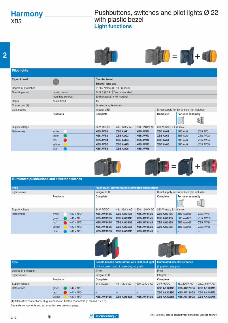
Other versions: please consult your Schneider Electric agency.
2
2/12
= +
= +
HarmonyXB5
Pilot lights
Type of head Circular bezel
Smooth lens cap
Degree of protection IP 66 / Nema 4X, 13 / Class II
Mounting (mm) panel cut-out Ø 22.5 (22.4 recommended)
mounting centres 30 (horizontal) x 40 (vertical)
Depth below head 43
Connection (1) Screw clamp terminals
Light source Integral LED Direct supply for BA 9s bulb (not included)
Products Complete Complete For user assembly
Supply voltage 24 V AC/DC 48…120 V AC 230…240 V AC 250 V max., 2.4 W max.
References white XB5 AVB1 XB5 AVG1 XB5 AVM1 XB5 AV61 ZB5 AV6 ZB5 AV01
green XB5 AVB3 XB5 AVG3 XB5 AVM3 XB5 AV63 ZB5 AV6 ZB5 AV03
red XB5 AVB4 XB5 AVG4 XB5 AVM4 XB5 AV64 ZB5 AV6 ZB5 AV04
yellow XB5 AVB5 XB5 AVG5 XB5 AVM5 XB5 AV65 ZB5 AV6 ZB5 AV05
blue XB5 AVB6 XB5 AVG6 XB5 AVM6 – – –
Illuminated pushbuttons and selector switches
Type Flush push, spring return, illuminated pushbuttons
Light source Integral LED Direct supply for BA 9s bulb (not included)
Products Complete Complete For user assembly
Supply voltage 24 V AC/DC 48…120 V AC 230…240 V AC 250 V max., 2.4 W max.
References white N/C + N/O XB5 AW31B5 XB5 AW31G5 XB5 AW31M5 XB5 AW3165 ZB5 AW065 ZB5 AW31
green N/C + N/O XB5 AW33B5 XB5 AW33G5 XB5 AW33M5 XB5 AW3365 ZB5 AW065 ZB5 AW33
red N/C + N/O XB5 AW34B5 XB5 AW34G5 XB5 AW34M5 XB5 AW3465 ZB5 AW065 ZB5 AW34
yellow N/C + N/O XB5 AW35B5 XB5 AW35G5 XB5 AW35M5 XB5 AW3565 ZB5 AW065 ZB5 AW35
blue N/C + N/O XB5 AW36B5 XB5 AW36G5 XB5 AW36M5 – – –
Type Double-headed pushbuttons with LED pilot light Illuminated selector switches
(1 flush green push, 1 projecting red push) (2 position stay put)
Degree of protection IP 40 IP 65
Light source Integral LED Integral LED
Products Complete Complete
Supply voltage 24 V AC/DC 48…120 V AC 230…240 V AC 24 V AC/DC 48…120 V AC 230…240 V AC
References green N/C + N/O – – – XB5 AK123B5 XB5 AK123G5 XB5 AK123M5
red N/C + N/O – – – XB5 AK124B5 XB5 AK124G5 XB5 AK124M5
yellow N/C + N/O XB5 AW84B5 XB5 AW84G5 XB5 AW84M5 XB5 AK125B5 XB5 AK125G5 XB5 AK125M5
(1) Alternative connections: plug-in connector, Faston connectors (6.35 and 2 x 2.8).
Separate components and accessories: see previous page.
+ 0.40
Pushbuttons, switches and pilot lights Ø 22with plastic bezelLight functions

Other versions: please consult your Schneider Electric agency.
2
2/13
Control stationsFor XB5 pushbuttons, switches and pilot lightsØ 22 with plastic bezel
Complete stations with 1 pushbutton, selector switch or key switch(light grey RAL 7035 base with dark grey RAL 7016 lid)Degree of protection IP 65 / Nema 4X and 13 / Class II
Dimensions (mm) W x H x D 68 x 68 x 113 max. (with key release Ø 40 mushroom head pushbutton)
Fixing (mm) 2 x Ø 4.3 on 54 mm centres
Function 1 Start or Stop function 1 Start-Stop function
Marking On spring return push On legend holder and legend below head
Number and type of pushbutton/selector switch/key switch 1 flush green p/b 1 flush red p/b 1 projecting red p/b 1 2 position stay put selector switch or key switch
Black handle Key n° 455 (key withdrawal LH pos.)
References N/O I XAL D102 – – – –
Start XAL D103 – – – –
O - I – – – XAL D134 XAL D144
N/C O – XAL D112 XAL D115 – –
Function Emergency stop (2) (light grey RAL 7035 base with yellow RAL 1012 lid)
Number and type of mushroom head pushbutton 1 red Ø 40 head, turn to release 1 red Ø 40 head, key release
Latching mechanism Trigger action (EN 418) Latching Latching
References N/C – XAL K174 XAL K184
N/C + N/C XAL K178F XAL K174F XAL K184F
N/C + N/O XAL K178E XAL K174E XAL K184E
N/C + N/C + N/O XAL K178G XAL K174G XAL K184G
(2) The mushroom head Emergency stop pushbuttons conform to standard IEC/EN 60947-5-5 and Machinery Directive 98/37/EC.
Trigger action mushroom head pushbuttons conform to standard EN 418.
Complete stations with 2 and 3 pushbuttons or 2 pushbuttons + 1 pilot light(light grey RAL 7035 base with dark grey RAL 7016 lid)Dimensions (mm) W x H x D 2-way control stations: 68 x 106 x 62; 3-way control stations: 68 x 136 x 87
Fixing (mm) 2-way control stations: 2 x Ø 4.3 on 54 x 68 centres; 3-way control stations: 2 x Ø 4.3 on 54 x 98 centres
Function Start-Stop functions 2 functions 3 functions
Marking On spring return push
Number and type of pushbutton/pilot light 1 flush green p/b 1 flush green pushbutton 1 flush white p/b 1 flush white p/b 1 flush white p/b
1 flush red p/b 1 flush red pushbutton 1 flush black p/b 1 flush red p/b 1 Ø 30 red mush-
1 red pilot light with integral LED (1) 1 flush black p/b room head p/b
1 flush black p/b
24 V AC/DC 230 V AC
References N/O + N/C I - O XAL D213 XAL D363B XAL D363M – – –
Start - Stop XAL D215 – – – – –
N/O + N/O – – – XAL D222 – –
N/O + N/C + N/O – – – – XAL D324 XAL D328
Accessories Standard contact blocks (1) Light blocks with integral LED, colour red
Description N/O contact N/C contact 24 V AC/DC 230 V AC
References ZEN L1111 ZEN L1121 ZAL VB4 ZAL VM4
HarmonyXAL
(1):
Number of cut-outs Number (p)
1 1
2 2
3 3
4 4
5 5
(1) Empty enclosures:Basic reference: XAL K0p, replace the pby the number of cut-outs required (seecut-out table above)
(1) Empty enclosures:Basic reference: XAL K0p, replace the pby the number of cut-outs required (seecut-out table above)
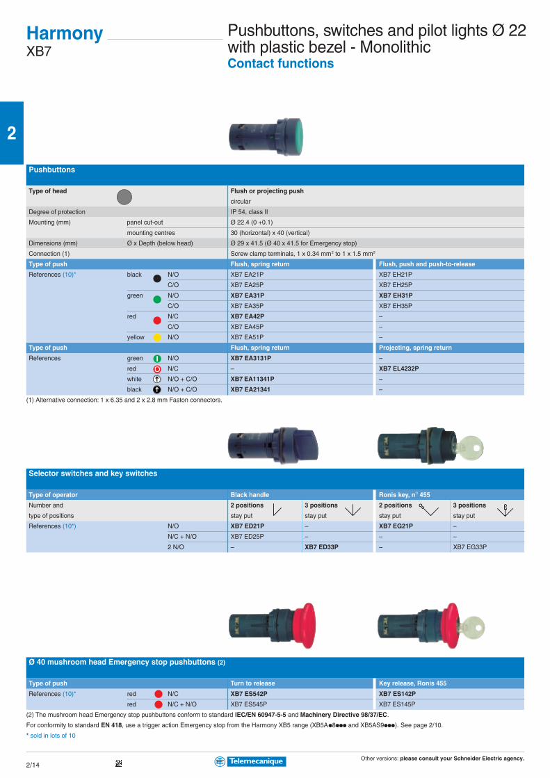
Other versions: please consult your Schneider Electric agency.
2
2/14
Pushbuttons
Type of head Flush or projecting push
circular
Degree of protection IP 54, class II
Mounting (mm) panel cut-out Ø 22.4 (0 +0.1)
mounting centres 30 (horizontal) x 40 (vertical)
Dimensions (mm) Ø x Depth (below head) Ø 29 x 41.5 (Ø 40 x 41.5 for Emergency stop)
Connection (1) Screw clamp terminals, 1 x 0.34 mm2 to 1 x 1.5 mm2
Type of push Flush, spring return Flush, push and push-to-release
References (10)* black N/O XB7 EA21P XB7 EH21P
C/O XB7 EA25P XB7 EH25P
green N/O XB7 EA31P XB7 EH31P
C/O XB7 EA35P XB7 EH35P
red N/C XB7 EA42P –
C/O XB7 EA45P –
yellow N/O XB7 EA51P –
Type of push Flush, spring return Projecting, spring return
References green N/O XB7 EA3131P –
red N/C – XB7 EL4232P
white N/O + C/O XB7 EA11341P –
black N/O + C/O XB7 EA21341 –
(1) Alternative connection: 1 x 6.35 and 2 x 2.8 mm Faston connectors.
Selector switches and key switches
Type of operator Black handle Ronis key, n° 455
Number and 2 positions 3 positions 2 positions 3 positions
type of positions stay put stay put stay put stay put
References (10*) N/O XB7 ED21P – XB7 EG21P –
N/C + N/O XB7 ED25P – – –
2 N/O – XB7 ED33P – XB7 EG33P
Ø 40 mushroom head Emergency stop pushbuttons (2)
Type of push Turn to release Key release, Ronis 455
References (10)* red N/C XB7 ES542P XB7 ES142P
red N/C + N/O XB7 ES545P XB7 ES145P
(2) The mushroom head Emergency stop pushbuttons conform to standard IEC/EN 60947-5-5 and Machinery Directive 98/37/EC.
For conformity to standard EN 418, use a trigger action Emergency stop from the Harmony XB5 range (XB5Ap8ppp and XB5AS9ppp). See page 2/10.
* sold in lots of 10
HarmonyXB7
Pushbuttons, switches and pilot lights Ø 22with plastic bezel - MonolithicContact functions
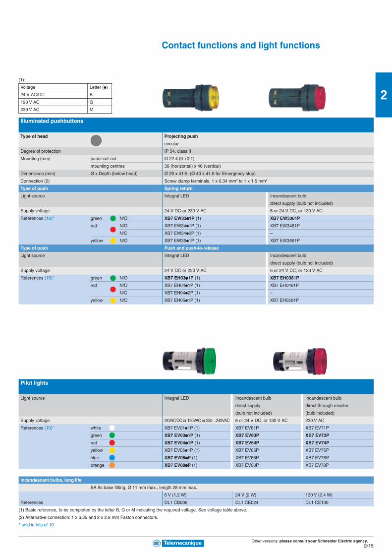
Other versions: please consult your Schneider Electric agency.
2
2/15
Illuminated pushbuttons
Type of head Projecting push
circular
Degree of protection IP 54, class II
Mounting (mm) panel cut-out Ø 22.4 (0 +0.1)
mounting centres 30 (horizontal) x 40 (vertical)
Dimensions (mm) Ø x Depth (below head) Ø 29 x 41.5, (Ø 40 x 41.5 for Emergency stop)
Connection (2) Screw clamp terminals, 1 x 0.34 mm2 to 1 x 1.5 mm2
Type of push Spring return
Light source Integral LED Incandescent bulb
direct supply (bulb not included)
Supply voltage 24 V DC or 230 V AC 6 or 24 V DC, or 130 V AC
References (10)* green N/O XB7 EW33ppppp1P (1) XB7 EW3361P
red N/O XB7 EW34p1P (1) XB7 EW3461P
N/C XB7 EW34p2P (1) –
yellow N/O XB7 EW35p1P (1) XB7 EW3561P
Type of push Push and push-to-release
Light source Integral LED Incandescent bulb
direct supply (bulb not included)
Supply voltage 24 V DC or 230 V AC 6 or 24 V DC, or 130 V AC
References (10)* green N/O XB7 EH03ppppp1P (1) XB7 EH0361P
red N/O XB7 EH04p1P (1) XB7 EH0461P
N/C XB7 EH04p2P (1) –
yellow N/O XB7 EH05p1P (1) XB7 EH0561P
Pilot lights
Light source Integral LED Incandescent bulb Incandescent bulb
direct supply direct through resistor
(bulb not included) (bulb included)
Supply voltage 24VAC/DC or 120VAC or 230…240VAC 6 or 24 V DC, or 130 V AC 230 V AC
References (10)* white XB7 EV01p1P (1) XB7 EV61P XB7 EV71P
green XB7 EV03ppppp1P (1) XB7 EV63P XB7 EV73P
red XB7 EV04ppppp1P (1) XB7 EV64P XB7 EV74P
yellow XB7 EV05p1P (1) XB7 EV65P XB7 EV75P
blue XB7 EV06pppppP (1) XB7 EV66P XB7 EV76P
orange XB7 EV08pppppP (1) XB7 EV68P XB7 EV78P
Incandescent bulbs, long life
BA 9s base fitting, Ø 11 mm max., length 28 mm max.
6 V (1.2 W) 24 V (2 W) 130 V (2.4 W)
References DL1 CB006 DL1 CE024 DL1 CE130
(1) Basic reference, to be completed by the letter B, G or M indicating the required voltage. See voltage table above.
(2) Alternative connection: 1 x 6.35 and 2 x 2.8 mm Faston connectors.
* sold in lots of 10
Contact functions and light functions
(1):
Voltage Letter (p)
24 V AC/DC B
120 V AC G
230 V AC M
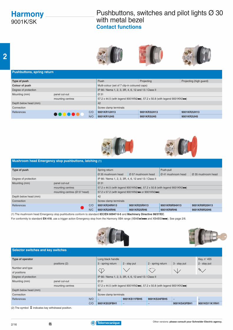
Other versions: please consult your Schneider Electric agency.
2
2/16
Pushbuttons, spring return
Type of push Flush Projecting Projecting (high guard)
Colour of push Multi-colour (set of 7 clip-in coloured caps)
Degree of protection IP 66 / Nema 1, 2, 3, 3R, 4, 6, 12 and 13 / Class II
Mounting (mm) panel cut-out Ø 31
mounting centres 57.2 x 44.5 (with legend 9001KN2pp), 57.2 x 50.8 (with legend 9001KN3pp)
Depth below head (mm) 42
Connection Screw clamp terminals
References C/O 9001KR1UH13 9001KR3UH13 9001KR2UH13
N/O 9001KR1UH5 9001KR3UH5 9001KR2UH5
Mushroom head Emergency stop pushbuttons, latching (1)
Type of push Spring return Push-pull
Ø 35 mushroom head Ø 57 mushroom head Ø 41 mushroom head Ø 35 mushroom head
Degree of protection IP 66 / Nema 1, 2, 3, 3R, 4, 6, 12 and 13 / Class II
Mounting (mm) panel cut-out Ø 31
mounting centres 57.2 x 44.5 (with legend 9001KN2pp), 57.2 x 50.8 (with legend 9001KN3pp)
mounting centres (Ø 57 head) 57.2 x 57.2 (with legend 9001KN2pp or 9001KN3pp)
Depth below head (mm) 42
Connection Screw clamp terminals
References C/O 9001KR24RH13 9001KR25RH13 9001KR9R94H13 9001KR9R20H13
N/C 9001KR24RH6 9001KR25RH6 9001KR9RH6 9001KR9R20H6
(1) The mushroom head Emergency stop pushbuttons conform to standard IEC/EN 60947-5-5 and Machinery Directive 98/37/EC.
For conformity to standard EN 418, use a trigger action Emergency stop from the Harmony XB4 range (XB4Bp8ppp and XB4BS9ppp). See page 2/6.
Selector switches and key switches
Type of operator Long black handle Key, n° 455
positions (2) 3 - spring return 2 - stay put 2 - spring return 3 - stay put 2 - stay put
Number and type
of positions
Degree of protection IP 66 / Nema 1, 2, 3, 3R, 4, 6, 12 and 13 / Class II
Mounting (mm) panel cut-out Ø 31
mounting centres 57.2 x 44.5 (with legend 9001KN2pp), 57.2 x 50.8 (with legend 9001KN3pp)
Depth below head (mm) 42
Connection Screw clamp terminals
References N/O – 9001KS11FBH5 9001KS34FBH5 – –
C/O 9001KS53FBH1 – – 9001KS43FBH1 9001KS11K1RH1
(2) The symbol indicates key withdrawal position.
Harmony9001K/SK
Pushbuttons, switches and pilot lights Ø 30with metal bezelContact functions
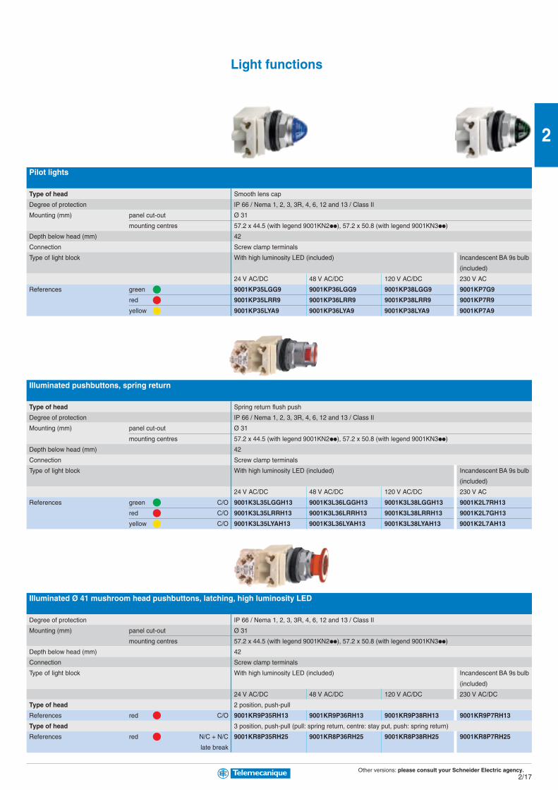
Other versions: please consult your Schneider Electric agency.
2
2/17
Pilot lights
Type of head Smooth lens cap
Degree of protection IP 66 / Nema 1, 2, 3, 3R, 4, 6, 12 and 13 / Class II
Mounting (mm) panel cut-out Ø 31
mounting centres 57.2 x 44.5 (with legend 9001KN2pp), 57.2 x 50.8 (with legend 9001KN3pp)
Depth below head (mm) 42
Connection Screw clamp terminals
Type of light block With high luminosity LED (included) Incandescent BA 9s bulb
(included)
24 V AC/DC 48 V AC/DC 120 V AC/DC 230 V AC
References green 9001KP35LGG9 9001KP36LGG9 9001KP38LGG9 9001KP7G9
red 9001KP35LRR9 9001KP36LRR9 9001KP38LRR9 9001KP7R9
yellow 9001KP35LYA9 9001KP36LYA9 9001KP38LYA9 9001KP7A9
Illuminated pushbuttons, spring return
Type of head Spring return flush push
Degree of protection IP 66 / Nema 1, 2, 3, 3R, 4, 6, 12 and 13 / Class II
Mounting (mm) panel cut-out Ø 31
mounting centres 57.2 x 44.5 (with legend 9001KN2pp), 57.2 x 50.8 (with legend 9001KN3pp)
Depth below head (mm) 42
Connection Screw clamp terminals
Type of light block With high luminosity LED (included) Incandescent BA 9s bulb
(included)
24 V AC/DC 48 V AC/DC 120 V AC/DC 230 V AC
References green C/O 9001K3L35LGGH13 9001K3L36LGGH13 9001K3L38LGGH13 9001K2L7RH13
red C/O 9001K3L35LRRH13 9001K3L36LRRH13 9001K3L38LRRH13 9001K2L7GH13
yellow C/O 9001K3L35LYAH13 9001K3L36LYAH13 9001K3L38LYAH13 9001K2L7AH13
Illuminated Ø 41 mushroom head pushbuttons, latching, high luminosity LED
Degree of protection IP 66 / Nema 1, 2, 3, 3R, 4, 6, 12 and 13 / Class II
Mounting (mm) panel cut-out Ø 31
mounting centres 57.2 x 44.5 (with legend 9001KN2pp), 57.2 x 50.8 (with legend 9001KN3pp)
Depth below head (mm) 42
Connection Screw clamp terminals
Type of light block With high luminosity LED (included) Incandescent BA 9s bulb
(included)
24 V AC/DC 48 V AC/DC 120 V AC/DC 230 V AC/DC
Type of head 2 position, push-pull
References red C/O 9001KR9P35RH13 9001KR9P36RH13 9001KR9P38RH13 9001KR9P7RH13
Type of head 3 position, push-pull (pull: spring return, centre: stay put, push: spring return)
References red N/C + N/C 9001KR8P35RH25 9001KR8P36RH25 9001KR8P38RH25 9001KR8P7RH25
late break
Light functions

Other versions: please consult your Schneider Electric agency.
2
2/18
Pushbuttons, spring return
Type of push Flush Projecting Projecting (high guard)
Colour of push Multi-colour (set of 7 clip-in coloured caps)
Degree of protection IP 66 / Nema 1, 2, 3, 3R, 4, 4X, 12 and 13 / Class II
Mounting (mm) panel cut-out Ø 31
mounting centres 57.2 x 44.5 (with legend 9001KN2pp), 57.2 x 50.8 (with legend 9001KN3pp)
Depth below head (mm) 42
Connection Screw clamp terminals
References C/O 9001SKR1UH13 9001SKR3UH13 9001SKR2UH13
N/O 9001SKR1UH5 9001SKR3UH5 9001SKR2UH5
Selector switches
Type of operator Long black handle
positions 3 - spring return 2 - stay put 2 - spring return 3 - stay put
Number and type
of positions
Degree of protection IP 66 / Nema 1, 2, 3, 3R, 4, 4X, 12 and 13 / Class II
Mounting (mm) panel cut-out Ø 31
mounting centres 57.2 x 44.5 (with legend 9001KN2pp), 57.2 x 50.8 (with legend 9001KN3pp)
Depth below head (mm) 42
Connection Screw clamp terminals
References N/O – 9001SKS11FBH5 9001SKS34FBH5 –
C/O 9001SKS53FBH1 – – 9001SKS43FBH1
Pilot lights
Type of head Smooth lens cap
Degree of protection IP 66 / Nema 1, 2, 3, 3R, 4, 4X, 12 and 13 / Class II
Mounting (mm) panel cut-out Ø 31
mounting centres 57.2 x 44.5 (with legend 9001KN2pp), 57.2 x 50.8 (with legend 9001KN3pp)
Depth below head (mm) 42
Connection Screw clamp terminals
Type of light block With high luminosity LED (included) Incandescent BA 9s bulb
(included)
24 V AC/DC 48 V AC/DC 120 V AC/DC 230 V AC
References green 9001SKP35LGG9 9001SKP36LGG9 9001SKP38LGG9 9001SKP7G9
red 9001SKP35LRR9 9001SKP36LRR9 9001SKP38LRR9 9001SKP7R9
yellow 9001SKP35LYA9 9001SKP36LYA9 9001SKP38LYA9 9001SKP7A9
Harmony9001K/SK
Pushbuttons, switches and pilot lights Ø 30with plastic bezelContact functions and light functions

Other versions: please consult your Schneider Electric agency.
2
2/19
Contact blocks with protected terminals
Type of contact Single contact blocks
Connection Screw clamp terminals
References C/O 9001KA1
N/O 9001KA2
N/C 9001KA3
C/O, late break 9001KA4
N/C, late break 9001KA5
N/O, early make 9001KA6
Enclosures
Type Number of Ø 30 mm cut-outs NEMA ratings Reference
Aluminium 1 1, 3, 4, 6, 12, 13 9001KY1
2 1, 3, 4, 6, 12, 13 9001KY2
3 1, 3, 4, 6, 12, 13 9001KY3
4 1, 3, 4, 6, 12, 13 9001KY4
Stainless steel 1 1, 3, 4, 4X, 13 9001KYSS1
2 1, 3, 4, 4X, 13 9001KYSS2
3 1, 3, 4, 4X, 13 9001KYSS3
Legends
Type Aluminium, size 44 x 43 mm Plastic, size 57 x 57 mm
Colour of legend black background white background
Marking Blank 9001KN200 9001KN100WP
START 9001KN201 9001KN101WP
STOP (red background) 9001KN202 9001KN102RP
FORWARD 9001KN206 9001KN106WP
REVERSE 9001KN207 9001KN107WP
CLOSE 9001KN208 9001KN108WP
OPEN 9001KN209 9001KN109WP
DOWN 9001KN210 9001KN110WP
UP 9001KN211 9001KN111WP
HIGH 9001KN214 9001KN114WP
LOW 9001KN215 9001KN115WP
RESET 9001KN223 9001KN123WP
PULL TO START/ 9001KN379 9001KN179WP
PUSH TO STOP
Accessories
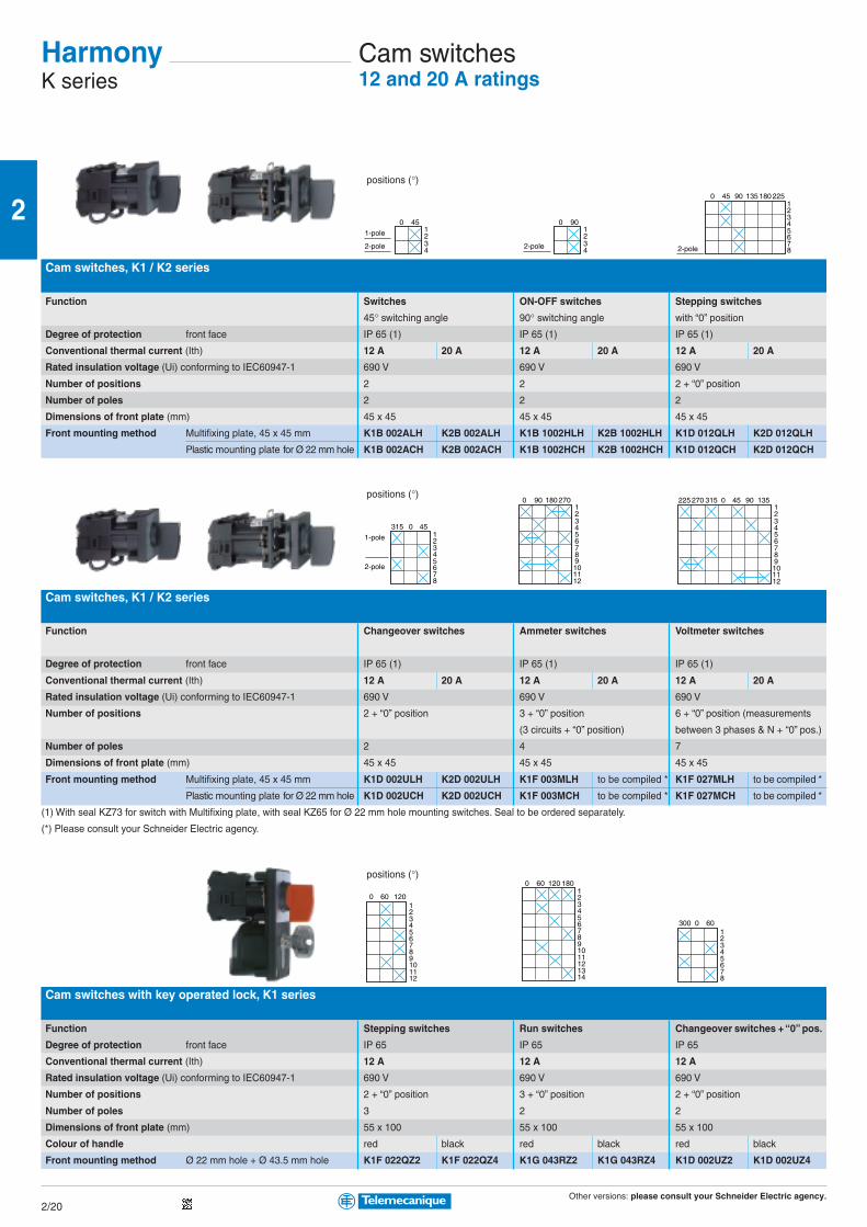
Other versions: please consult your Schneider Electric agency.
2
2/20
12
450
34
1-pole
2-pole
12
900
342-pole
901
450
2345678
135 180 225
2-pole
451
0315
2345678
1-pole
2-pole
1801234
900 270
56789101112
01234
315270
5678
225
910
45 90
1112
135
0123456789101112
60 1201234567891011121314
120 1800 60
30012345678
0 60
Cam switches12 and 20 A ratings
Cam switches, K1 / K2 series
Function Switches ON-OFF switches Stepping switches
45° switching angle 90° switching angle with “0” position
Degree of protection front face IP 65 (1) IP 65 (1) IP 65 (1)
Conventional thermal current (Ith) 12 A 20 A 12 A 20 A 12 A 20 A
Rated insulation voltage (Ui) conforming to IEC60947-1 690 V 690 V 690 V
Number of positions 2 2 2 + “0” position
Number of poles 2 2 2
Dimensions of front plate (mm) 45 x 45 45 x 45 45 x 45
Front mounting method Multifixing plate, 45 x 45 mm K1B 002ALH K2B 002ALH K1B 1002HLH K2B 1002HLH K1D 012QLH K2D 012QLH
Plastic mounting plate for Ø 22 mm hole K1B 002ACH K2B 002ACH K1B 1002HCH K2B 1002HCH K1D 012QCH K2D 012QCH
Cam switches, K1 / K2 series
Function Changeover switches Ammeter switches Voltmeter switches
Degree of protection front face IP 65 (1) IP 65 (1) IP 65 (1)
Conventional thermal current (Ith) 12 A 20 A 12 A 20 A 12 A 20 A
Rated insulation voltage (Ui) conforming to IEC60947-1 690 V 690 V 690 V
Number of positions 2 + “0” position 3 + “0” position 6 + “0” position (measurements
(3 circuits + “0” position) between 3 phases & N + “0” pos.)
Number of poles 2 4 7
Dimensions of front plate (mm) 45 x 45 45 x 45 45 x 45
Front mounting method Multifixing plate, 45 x 45 mm K1D 002ULH K2D 002ULH K1F 003MLH to be compiled * K1F 027MLH to be compiled *
Plastic mounting plate for Ø 22 mm hole K1D 002UCH K2D 002UCH K1F 003MCH to be compiled * K1F 027MCH to be compiled *
(1) With seal KZ73 for switch with Multifixing plate, with seal KZ65 for Ø 22 mm hole mounting switches. Seal to be ordered separately.
(*) Please consult your Schneider Electric agency.
Cam switches with key operated lock, K1 series
Function Stepping switches Run switches Changeover switches + “0” pos.
Degree of protection front face IP 65 IP 65 IP 65
Conventional thermal current (Ith) 12 A 12 A 12 A
Rated insulation voltage (Ui) conforming to IEC60947-1 690 V 690 V 690 V
Number of positions 2 + “0” position 3 + “0” position 2 + “0” position
Number of poles 3 2 2
Dimensions of front plate (mm) 55 x 100 55 x 100 55 x 100
Colour of handle red black red black red black
Front mounting method Ø 22 mm hole + Ø 43.5 mm hole K1F 022QZ2 K1F 022QZ4 K1G 043RZ2 K1G 043RZ4 K1D 002UZ2 K1D 002UZ4
HarmonyK series
positions (°)
positions (°)
positions (°)
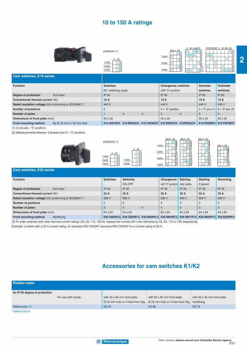
Other versions: please consult your Schneider Electric agency.
2
2/21
0123456
60
1-pole
2-pole
3-pole
012
60
34
300
56789101112
1-pole
2-pole
3-pole
9012
180
34
0 270
56789101112
30012
330
34
270 0 30 60 90
56789101112
0123456
601-pole
2-pole
3-pole
012345678
90
1-pole
2-pole
012
60
34
1234
300
5678910111213141516
1-pole
2-pole
3-pole
4-pole
012
60
34
1234
300
5678910111213141516
012
60
34
1234
300
5678910111213141516
012
60
34
1234
300
56789101112
10 to 150 A ratings
Cam switches, K10 series
Function Switches Changeover switches Ammeter Voltmeter
60° switching angle with “0” position switches switches
Degree of protection front face IP 65 IP 65 IP 65 IP 65
Conventional thermal current (Ith) 10 A 10 A 10 A 10 A
Rated insulation voltage (Ui) conforming to IEC60947-1 440 V 440 V 440 V 440 V
Number of positions 2 2 + “0” position 3 + “0” pos. (1) 6 + “0” pos. (2)
Number of poles 1 2 3 2 3 3 3
Dimensions of front plate (mm) 30 x 30 30 x 30 30 x 30 30 x 30
Front mounting method By Ø 16 mm or 22 mm hole K10 A001ACH K10 B002ACH K10 C003ACH K10 D002UCH K10F003UCH K10 F003MCH K10 F027MCH
(1) (3 circuits + “0” position).
(2) (Measurements between 3 phases and N + “0” position).
Cam switches, K30 series
Function Switches Switches Changeover Starting Starting Reversing
ON-OFF with “0” position star-delta 2-speed
Degree of protection front face IP 40 IP 40 IP 40 IP 40 IP 40 IP 40
Conventional thermal current (Ith) 32 A 32 A 32 A 32 A 32 A 32 A
Rated insulation voltage (Ui) conforming to IEC60947-1 690 V 690 V 690 V 690 V 690 V 690 V
Number of positions 2 2 3 3 3 3
Number of poles 3 3 4 4 3 3 3
Dimensions of front plate (mm) 64 x 64 64 x 64 64 x 64 64 x 64 64 x 64 64 x 64
Front mounting method Multifixing K30 C003AP (3) K30 C003HP (3) K30 D004HP (3) K30 H004UP (3) K30 H001YP (3) K30 H004PP (3) K30 E003WP(3)
(3) To order switches with other thermal current ratings (50, 63, 115, 150 A): replace the number 30 in the reference by 50, 63, 115 or 150 respectively.
Example: a switch with a 32 A current rating, for example K30 C003AP, becomes K50 C003AP for a current rating of 50 A.
Accessories for cam switches K1/K2
Rubber seals
for IP 65 degree of protection
For use with heads with 45 x 45 mm front plate with 60 x 60 mm front plate with 45 x 45 mm front plate
Ø 22 mm hole or 4 hole front mtg. Ø 22 mm hole or 4 hole front mtg. multifixing
References (5)* KZ 65 KZ 66 KZ 73
* sold in lots of
positions (°)
positions (°)

Other versions: please consult your Schneider Electric agency.
2
2/22
Beacons and indicator banksUniversal - For signalling from 35 to 50 m
Illuminated beacons XVB L Steady light signalling Flashing light signalling
Light source Incandescent BA 15d bulb, Protected BA 15d LED Protected BA 15d LED “Flash” discharge tube
10 W max. (not included) (included) (included) 5 J (1)
Degree of protection IP 66
Beacon references (2) 12…250 V AC/DC XVBL3ppppp – – –
24 V AC/DC – XVBL0Bppppp XVBL1Bppppp XVBL6Bppppp
120 V AC – XVBL0Gppppp XVBL1Gppppp XVBL6Gppppp
230 V AC – XVBL0Mppppp XVBL1Mppppp XVBL6Mppppp
Indicator banks XVB C Base units Steady light signalling Flashing “Flash” Audiblecomprising 2 to 5 signalling units (3) light light units (90 db
signalling signalling at 1 m)Light source – Incandescent Integral Integral “Flash” –
BA 15d bulb, 10 W protected LED protected LED discharge tube
max. (not included) 5 J (1)
Degree of protection IP 66
Base unit references with cover XVBC21 (4) – – – – –
without cover XVBC07 (5) – – – – –
Lens unit references (2) 12… 230 V AC/DC – XVBC3ppppp – – – –
24 V AC/DC – – XVBC2Bppppp XVBC5Bppppp XVBC6Bppppp –
120 V AC – – XVBC2Gppppp XVBC5Gppppp XVBC6Gppppp –
230 V AC – – XVBC2Mppppp XVBC5Mppppp XVBC6Mppppp –
Audible unit references 12…48 V AC/DC – – – – – XVBC9B
unidirectional 120…230 V AC – – – – – XVBC9M
(4) For connection on AS-Interface, order base unit XVBC21A (side cable entry) or XVBC21B (bottom cable entry with M12 connector on flying lead).
(5) For indicator banks with “flash” discharge tube unit.
Indicator banks XVP C Base unit Steady or “Flash” light signalling Audible unitscomprising 2 to 5 signalling units (3), flashing light (55…85 dBblack clamping ring (6) signalling at 1 m)Light source – Incandescent “Flash” “Flash” –
BA 15d bulb, 7 W discharge tube discharge tube
max. (not included) 0.3 J 0.6 J
Degree of protection IP 65
Base unit with cover XVPC21 – – – –
References (2) 250 V max. – XVPC3ppppp – – –
24 V AC/DC (flash) - 24 V DC (buzzer) – – XVPC6Bppppp – XVPC09B
120 V AC – – – XVPC6Gppppp XVPC09G
230 V AC – – – XVPC6Mppppp XVPC09M
(1) To order a lens unit with a 10 J discharge tube, replace the number 6 by 8 in the reference (example: XVBL6Bp becomes XVBL8Bp).
(2) To obtain the complete reference, replace the p by the number designating the colour as follows: 3 = green , 4 = red , 5 = orange, 6 = blue, 7 = clear, 8 = yellow.
(3) An indicator bank comprises: 1 base unit + 1 to 5 signalling units maximum.
(6) To order products with a cream clamping ring, add the letter W to the end of the reference (example: base unit + green lens unit: XVPC21W + XVPC33W etc.).
HarmonyXVB / XVP
XVB XVP
Universal rangeHigh performance and wide choice of units
Ø 70 mm
Ø 70 mm
Ø 50 mm
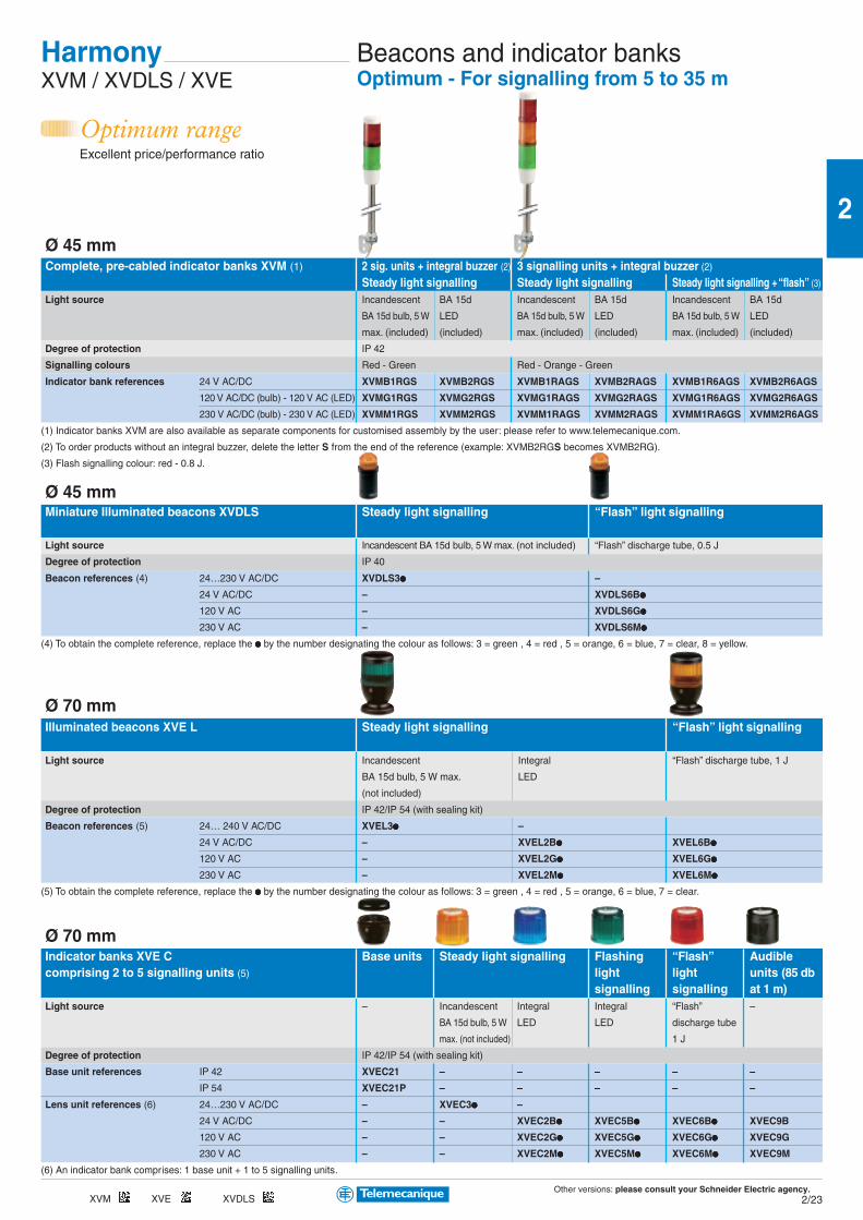
Other versions: please consult your Schneider Electric agency.
2
2/23
Complete, pre-cabled indicator banks XVM (1) 2 sig. units + integral buzzer (2) 3 signalling units + integral buzzer (2)
Steady light signalling Steady light signalling Steady light signalling + “flash” (3)
Light source Incandescent BA 15d Incandescent BA 15d Incandescent BA 15d
BA 15d bulb, 5 W LED BA 15d bulb, 5 W LED BA 15d bulb, 5 W LED
max. (included) (included) max. (included) (included) max. (included) (included)
Degree of protection IP 42
Signalling colours Red - Green Red - Orange - Green
Indicator bank references 24 V AC/DC XVMB1RGS XVMB2RGS XVMB1RAGS XVMB2RAGS XVMB1R6AGS XVMB2R6AGS
120 V AC/DC (bulb) - 120 V AC (LED) XVMG1RGS XVMG2RGS XVMG1RAGS XVMG2RAGS XVMG1R6AGS XVMG2R6AGS
230 V AC/DC (bulb) - 230 V AC (LED) XVMM1RGS XVMM2RGS XVMM1RAGS XVMM2RAGS XVMM1RA6GS XVMM2R6AGS
(1) Indicator banks XVM are also available as separate components for customised assembly by the user: please refer to www.telemecanique.com.
(2) To order products without an integral buzzer, delete the letter S from the end of the reference (example: XVMB2RGS becomes XVMB2RG).
(3) Flash signalling colour: red - 0.8 J.
Miniature Illuminated beacons XVDLS Steady light signalling “Flash” light signalling
Light source Incandescent BA 15d bulb, 5 W max. (not included) “Flash” discharge tube, 0.5 J
Degree of protection IP 40
Beacon references (4) 24…230 V AC/DC XVDLS3ppppp –
24 V AC/DC – XVDLS6Bppppp
120 V AC – XVDLS6Gppppp
230 V AC – XVDLS6Mppppp
(4) To obtain the complete reference, replace the ppppp by the number designating the colour as follows: 3 = green , 4 = red , 5 = orange, 6 = blue, 7 = clear, 8 = yellow.
Illuminated beacons XVE L Steady light signalling “Flash” light signalling
Light source Incandescent Integral “Flash” discharge tube, 1 J
BA 15d bulb, 5 W max. LED
(not included)
Degree of protection IP 42/IP 54 (with sealing kit)
Beacon references (5) 24… 240 V AC/DC XVEL3ppppp –
24 V AC/DC – XVEL2Bppppp XVEL6Bppppp
120 V AC – XVEL2Gppppp XVEL6Gppppp
230 V AC – XVEL2Mppppp XVEL6Mppppp
(5) To obtain the complete reference, replace the ppppp by the number designating the colour as follows: 3 = green , 4 = red , 5 = orange, 6 = blue, 7 = clear.
Indicator banks XVE C Base units Steady light signalling Flashing “Flash” Audiblecomprising 2 to 5 signalling units (5) light light units (85 db
signalling signalling at 1 m)Light source – Incandescent Integral Integral “Flash” –
BA 15d bulb, 5 W LED LED discharge tube
max. (not included) 1 J
Degree of protection IP 42/IP 54 (with sealing kit)
Base unit references IP 42 XVEC21 – – – – –
IP 54 XVEC21P – – – – –
Lens unit references (6) 24…230 V AC/DC – XVEC3ppppp –
24 V AC/DC – – XVEC2Bppppp XVEC5Bppppp XVEC6Bppppp XVEC9B
120 V AC – – XVEC2Gppppp XVEC5Gppppp XVEC6Gppppp XVEC9G
230 V AC – – XVEC2Mppppp XVEC5Mppppp XVEC6Mppppp XVEC9M
(6) An indicator bank comprises: 1 base unit + 1 to 5 signalling units.
Beacons and indicator banksOptimum - For signalling from 5 to 35 m
HarmonyXVM / XVDLS / XVE
Optimum rangeExcellent price/performance ratio
Ø 45 mm
Ø 45 mm
Ø 70 mm
Ø 70 mm
XVM XVE XVDLS
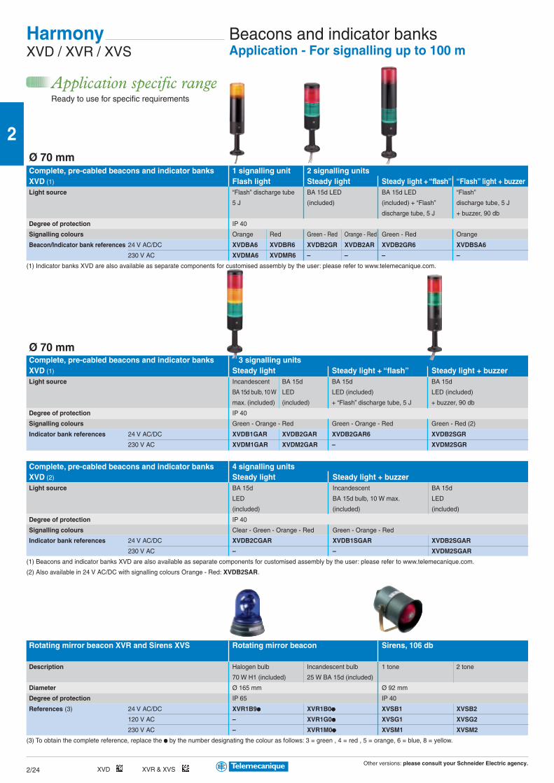
Other versions: please consult your Schneider Electric agency.
2
2/24
Beacons and indicator banksApplication - For signalling up to 100 m
Complete, pre-cabled beacons and indicator banks 1 signalling unit 2 signalling unitsXVD (1) Flash light Steady light Steady light + “flash” “Flash” light + buzzerLight source “Flash” discharge tube BA 15d LED BA 15d LED “Flash”
5 J (included) (included) + “Flash” discharge tube, 5 J
discharge tube, 5 J + buzzer, 90 db
Degree of protection IP 40
Signalling colours Orange Red Green - Red Orange - Red Green - Red Orange
Beacon/Indicator bank references 24 V AC/DC XVDBA6 XVDBR6 XVDB2GR XVDB2AR XVDB2GR6 XVDBSA6
230 V AC XVDMA6 XVDMR6 – – – –
(1) Indicator banks XVD are also available as separate components for customised assembly by the user: please refer to www.telemecanique.com.
Complete, pre-cabled beacons and indicator banks 3 signalling unitsXVD (1) Steady light Steady light + “flash” Steady light + buzzerLight source Incandescent BA 15d BA 15d BA 15d
BA 15d bulb, 10 W LED LED (included) LED (included)
max. (included) (included) + “Flash” discharge tube, 5 J + buzzer, 90 db
Degree of protection IP 40
Signalling colours Green - Orange - Red Green - Orange - Red Green - Red (2)
Indicator bank references 24 V AC/DC XVDB1GAR XVDB2GAR XVDB2GAR6 XVDB2SGR
230 V AC XVDM1GAR XVDM2GAR – XVDM2SGR
Complete, pre-cabled beacons and indicator banks 4 signalling unitsXVD (2) Steady light Steady light + buzzerLight source BA 15d Incandescent BA 15d
LED BA 15d bulb, 10 W max. LED
(included) (included) (included)
Degree of protection IP 40
Signalling colours Clear - Green - Orange - Red Green - Orange - Red
Indicator bank references 24 V AC/DC XVDB2CGAR XVDB1SGAR XVDB2SGAR
230 V AC – – XVDM2SGAR
(1) Beacons and indicator banks XVD are also available as separate components for customised assembly by the user: please refer to www.telemecanique.com.
(2) Also available in 24 V AC/DC with signalling colours Orange - Red: XVDB2SAR.
Rotating mirror beacon XVR and Sirens XVS Rotating mirror beacon Sirens, 106 db
Description Halogen bulb Incandescent bulb 1 tone 2 tone
70 W H1 (included) 25 W BA 15d (included)
Diameter Ø 165 mm Ø 92 mm
Degree of protection IP 65 IP 40
References (3) 24 V AC/DC XVR1B9ppppp XVR1B0ppppp XVSB1 XVSB2
120 V AC – XVR1G0ppppp XVSG1 XVSG2
230 V AC – XVR1M0ppppp XVSM1 XVSM2
(3) To obtain the complete reference, replace the ppppp by the number designating the colour as follows: 3 = green , 4 = red , 5 = orange, 6 = blue, 8 = yellow.
HarmonyXVD / XVR / XVS
Application specific rangeReady to use for specific requirements
Ø 70 mm
Ø 70 mm
XVD XVR & XVS
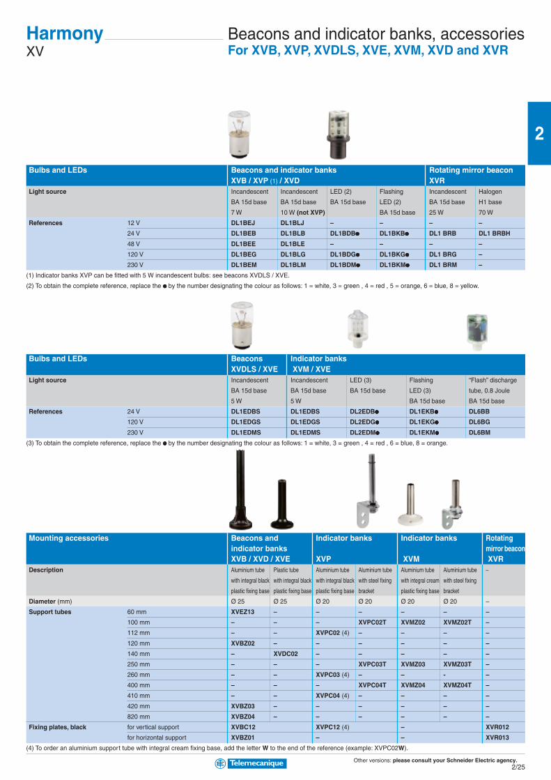
Other versions: please consult your Schneider Electric agency.
2
2/25
Beacons and indicator banks, accessoriesFor XVB, XVP, XVDLS, XVE, XVM, XVD and XVR
Bulbs and LEDs Beacons and indicator banks Rotating mirror beaconXVB / XVP (1) / XVD XVR
Light source Incandescent Incandescent LED (2) Flashing Incandescent Halogen
BA 15d base BA 15d base BA 15d base LED (2) BA 15d base H1 base
7 W 10 W (not XVP) BA 15d base 25 W 70 W
References 12 V DL1BEJ DL1BLJ – – – –
24 V DL1BEB DL1BLB DL1BDBppppp DL1BKBppppp DL1 BRB DL1 BRBH
48 V DL1BEE DL1BLE – – – –
120 V DL1BEG DL1BLG DL1BDGppppp DL1BKGppppp DL1 BRG –
230 V DL1BEM DL1BLM DL1BDMppppp DL1BKMppppp DL1 BRM –
(1) Indicator banks XVP can be fitted with 5 W incandescent bulbs: see beacons XVDLS / XVE.
(2) To obtain the complete reference, replace the ppppp by the number designating the colour as follows: 1 = white, 3 = green , 4 = red , 5 = orange, 6 = blue, 8 = yellow.
Bulbs and LEDs Beacons Indicator banksXVDLS / XVE XVM / XVE
Light source Incandescent Incandescent LED (3) Flashing “Flash” discharge
BA 15d base BA 15d base BA 15d base LED (3) tube, 0.8 Joule
5 W 5 W BA 15d base BA 15d base
References 24 V DL1EDBS DL1EDBS DL2EDBppppp DL1EKBppppp DL6BB
120 V DL1EDGS DL1EDGS DL2EDGppppp DL1EKGppppp DL6BG
230 V DL1EDMS DL1EDMS DL2EDMppppp DL1EKMppppp DL6BM
(3) To obtain the complete reference, replace the ppppp by the number designating the colour as follows: 1 = white, 3 = green , 4 = red , 6 = blue, 8 = orange.
Mounting accessories Beacons and Indicator banks Indicator banks Rotatingindicator banks mirror beaconXVB / XVD / XVE XVP XVM XVR
Description Aluminium tube Plastic tube Aluminium tube Aluminium tube Aluminium tube Aluminium tube –
with integral black with integral black with integral black with steel fixing with integral cream with steel fixing
plastic fixing base plastic fixing base plastic fixing base bracket plastic fixing base bracket
Diameter (mm) Ø 25 Ø 25 Ø 20 Ø 20 Ø 20 Ø 20 –
Support tubes 60 mm XVEZ13 – – – – – –
100 mm – – – XVPC02T XVMZ02 XVMZ02T –
112 mm – – XVPC02 (4) – – – –
120 mm XVBZ02 – – – – – –
140 mm – XVDC02 – – – – –
250 mm – – – XVPC03T XVMZ03 XVMZ03T –
260 mm – – XVPC03 (4) – – - –
400 mm – – – XVPC04T XVMZ04 XVMZ04T –
410 mm – – XVPC04 (4) – – – –
420 mm XVBZ03 – – – – – –
820 mm XVBZ04 – – – – – –
Fixing plates, black for vertical support XVBC12 XVPC12 (4) – XVR012
for horizontal support XVBZ01 – – XVR013
(4) To order an aluminium support tube with integral cream fixing base, add the letter W to the end of the reference (example: XVPC02W).
HarmonyXV

Other versions: please consult your Schneider Electric agency.
2
2/26
XAC
Type XAC A “Pistol grip”
Degree of protection IP 65 / Nema 4, 4X / Class II
Rated operational characteristics AC 15 (240 V 3 A), DC 13
Conventional thermal current Ithe 10 A
Connection Screw clamp terminals, 1 x 2.5 mm2 or 2 x 1.5 mm2
For control of single-speed motors 2-speed motors
Dimensions (mm) W x H x D 52 x 295 x 71 (x 85 with ZA2 BS44) 52 x 295 x 71 (x 85 with ZA2 BS44)
Number of operators mechanically interlocked 2 2
Emergency stop without ZA2 BS44 without ZA2 BS44
References XAC A201 XAC A2013 XAC A207 XAC A2073
Type XAC A
For control of single-speed motors
Dimensions (mm) W x H x D 80 x 314 x 70 (x 90 with ZA2 BS44) 80 x 440 x 70 (x 90 with ZA2 BS54)
Number of operators mechanically interlocked between pairs 2 4
Emergency stop without ZA2 BS44 without ZA2 BS54
References XAC A271 XAC A2713 XAC A471 XAC A4713
For control of single-speed motors
+ I / O
Dimensions (mm) W x H x D 80 x 500 x 70 (x 90 with ZA2 BS54) 80 x 560 x 70
Number of operators mechanically interlocked between pairs 6 8
Emergency stop without ZA2 BS54 without
References XAC A671 XAC A6713 XAC A871
Pendant control stationsfor control circuitsReady to use

Other versions: please consult your Schneider Electric agency.
2
2/27
XAC-A941
ZA2-BS834
ZA2-BS54
ZA2-BS
ZA2-BS14
ZB2-SZ3
ZA2-BD
XAC-B961
XAC-A009
XAC-S
ZB2-BE
XAC-A982
ZB2-BV00
XEN-G1 91
ZB2-BY
ZB2-BY
ZA2-BG
ZA2-BD
ZA2-BV0
Empty enclosures type XAC A
Number of ways 2 3 4 5 6 8 12
References XAC A02 XAC A03 XAC A04 XAC A05 XAC A06 XAC A08 XAC A12
Separate components (for mounting in enclosures XAC A)
Booted operators
white XAC A9411
black XAC A9412
Mushroom head, latching (1)
turn to release Ø 30 ZA2 BS44
Ø 40 ZA2 BS54
Mushroom head, latching, trigger action (1)
turn to release Ø 30 ZA2 BS834
Ø 40 ZA2 BS844
Mushroom head, latching (1)
key release Ø 30 ZA2 BS74
Ø 40 ZA2 BS14
Selector switch
2 pos. stay put ZA2 BD2
3 pos. stay put ZA2 BD3
Key switch
key n° 455 2 pos. stay put ZA2 BG4
3 pos. stay put ZA2 BG5
Blanking plug
Contact blocks with seal and ZB2 SZ3
Single-speed N/O ZB2 BE101 fixing nut
Single-speed N/C ZB2 BE102
Pilot light heads
Contacts blocks for XAC A941p white ZA2 BV01
Single-speed N/C + N/O XEN G1491 green ZA2 BV03
2-speed N/C + N/O + N/O XEN G1191 red ZA2 BV04
yellow ZA2 BV05
Contact blocks (for mounting in enclosure base) Protective guard (for base mounted units) Pilot light bodies
N/O XAC S101 For selector switch or XAC A982 direct supply ZB2 BV006
N/C + N/O XAC S105 mushroom head pushbutton direct supply, through resistor ZB2 BV007
Legends, 30 x 40 mm With symbols conforming to NF E 52-124 With text
References ZB2 BY4901 ZB2 BY4903 ZB2 BY4907 ZB2 BY4909 ZB2 BY4913 ZB2 BY4915 ZB2 BY4930 ZB2 BY2303 ZB2 BY2304
blank
white or yellow
background
References ZB2 BY2904 ZB2 BY2906 ZB2 BY2910 ZB2 BY2912 ZB2 BY2916 ZB2 BY2918 ZB2 BY2931 ZB2 BY4101
(1) The mushroom head Emergency stop pushbuttons conform to standard IEC/EN 60947-5-5 and Machinery Directive 98/37/EC.Trigger action mushroom head Emergency stop pushbuttons conform to standard EN 418.
Stations for user assembly
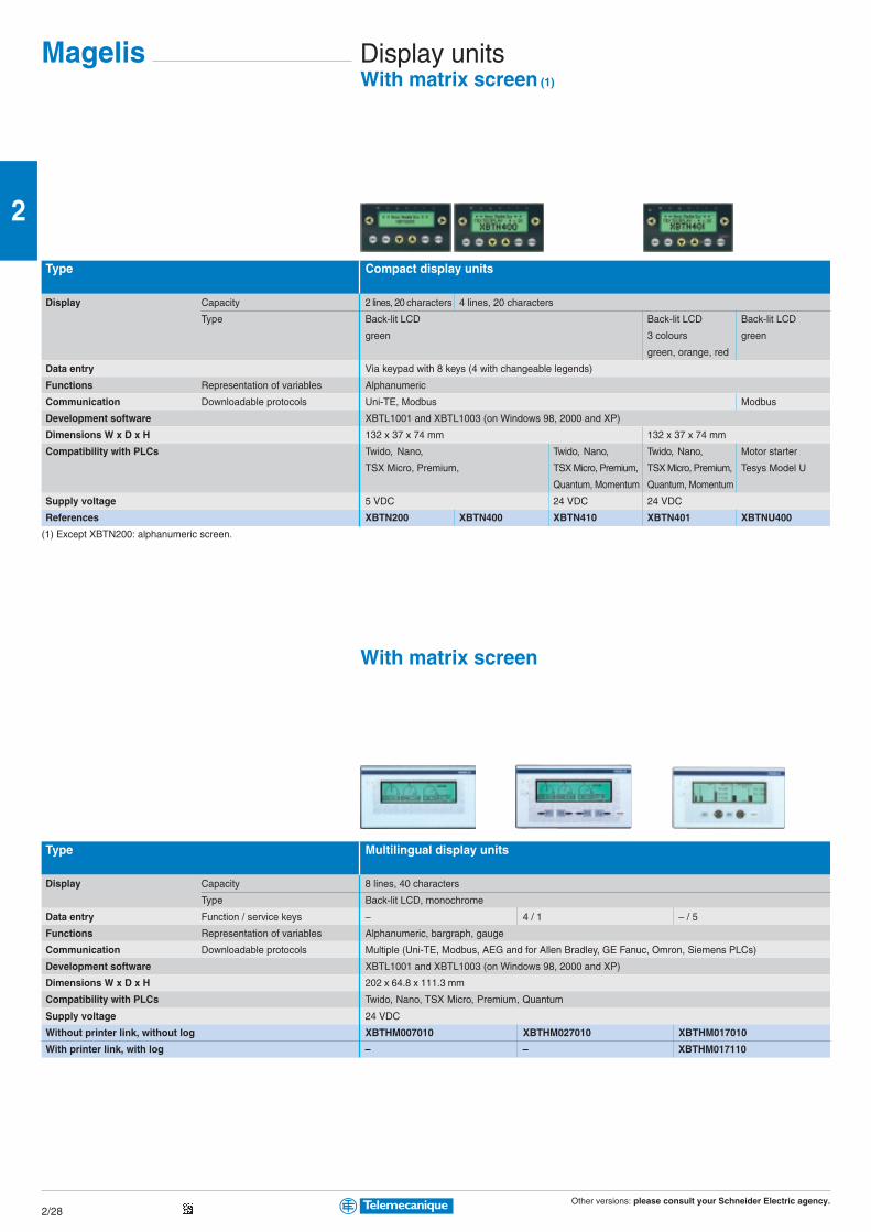
Other versions: please consult your Schneider Electric agency.2/28
2
Magelis Display unitsWith matrix screen (1)
Type Compact display units
Display Capacity 2 lines, 20 characters 4 lines, 20 characters
Type Back-lit LCD Back-lit LCD Back-lit LCD
green 3 colours green
green, orange, red
Data entry Via keypad with 8 keys (4 with changeable legends)
Functions Representation of variables Alphanumeric
Communication Downloadable protocols Uni-TE, Modbus Modbus
Development software XBTL1001 and XBTL1003 (on Windows 98, 2000 and XP)
Dimensions W x D x H 132 x 37 x 74 mm 132 x 37 x 74 mm
Compatibility with PLCs Twido, Nano, Twido, Nano, Twido, Nano, Motor starter
TSX Micro, Premium, TSX Micro, Premium, TSX Micro, Premium, Tesys Model U
Quantum, Momentum Quantum, Momentum
Supply voltage 5 VDC 24 VDC 24 VDC
References XBTN200 XBTN400 XBTN410 XBTN401 XBTNU400
(1) Except XBTN200: alphanumeric screen.
With matrix screen
Type Multilingual display units
Display Capacity 8 lines, 40 characters
Type Back-lit LCD, monochrome
Data entry Function / service keys – 4 / 1 – / 5
Functions Representation of variables Alphanumeric, bargraph, gauge
Communication Downloadable protocols Multiple (Uni-TE, Modbus, AEG and for Allen Bradley, GE Fanuc, Omron, Siemens PLCs)
Development software XBTL1001 and XBTL1003 (on Windows 98, 2000 and XP)
Dimensions W x D x H 202 x 64.8 x 111.3 mm
Compatibility with PLCs Twido, Nano, TSX Micro, Premium, Quantum
Supply voltage 24 VDC
Without printer link, without log XBTHM007010 XBTHM027010 XBTHM017010
With printer link, with log – – XBTHM017110

Other versions: please consult your Schneider Electric agency.2/29
2
TerminalsWith matrix screen
Type Terminals
Display Capacity 4 lines, 20 characters
Type Back-lit LCD Back-lit LCD, 3 colours
green green, orange, red
Data entry 20 keys (12 configurable)
Functions Representation of variables Alphanumeric
Communication Downloadable protocols Uni-TE, Modbus
Development software XBTL1001 and XBTL1003 (on Windows 98, 2000 and XP)
Dimensions W x D x H 137 x 37 x 118 mm
Compatibility with PLCs Twido, Nano, Twido, Nano, TSX Micro,
TSX Micro, Premium, Premium, Quantum, Momentum
Supply voltage 5 VDC 24 VDC
References XBTR400 XBTR410 XBTR411
With matrix screen
Type 8 line multilingual matrix screen terminals
Display Capacity 8 lines, 40 characters
Type Back-lit LCD, monochrome
Data entry Function / service keys 12 / 10
Numeric / soft function keys 12 / 4
Functions Representation of variables Alphanumeric, bargraph, gauge
Communication Downloadable protocols Multiple (Uni-TE, Modbus, AEG and for Allen Bradley, GE Fanuc, Omron, Siemens PLCs)
Development software XBTL1001 and XBTL1003 (on Windows 98, 2000 and XP)
Dimensions W x D x H 253 x 62.5 x 155 mm
Compatibility with PLCs Twido, Nano, TSX Micro, Premium
Supply voltage 24 VDC
Without printer link, without log XBTPM027010
With printer link, with log XBTPM027110
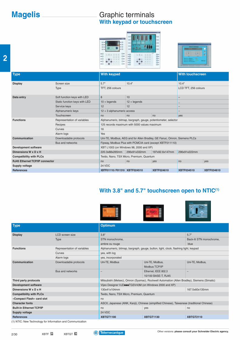
Other versions: please consult your Schneider Electric agency.2/30
2
Magelis Graphic terminalsWith keypad or touchscreen
Type With keypad With touchscreen
Display Screen size 5.7" 10.4" 10.4"
Type TFT, 256 colours LCD TFT, 256 colours
Data entry Soft function keys with LED 8 10 –
Static function keys with LED 10 + legends 12 + legends _
Service keys 12 12 –
Alphanumeric keys 12 + 3 alphanumeric access –
Touchscreen no no no yes
Functions Representation of variables Alphanumeric, bitmap, bargraph, gauge, potentiometer, selector
Recipes 125 records maximum with 5000 values maximum
Curves 16
Alarm logs Yes
Communication Downloadable protocols Uni-TE, Modbus, AEG and for Allen Bradley, GE Fanuc, Omron, Siemens PLCs
Bus and networks Fipway, Modbus Plus with PCMCIA card (except XBTF011110)
Development software XBT L1003 (on Windows 98, 2000 and XP)
Dimensions W x D x H 220.3x88x265mm 296x91x332mm 197x92.6x147mm 296x91x222mm
Compatibility with PLCs Twido, Nano, TSX Micro, Premium, Quantum
RJ45 Ethernet TCP/IP connector no no yes no yes
Supply voltage 24 VDC
References XBTF011110 / F011310 XBTF024510 XBTF024610 XBTF034510 XBTF034610
With 3.8" and 5.7" touchscreen open to NTIC(1)
Type Optimum
Display LCD screen size 3.8" 5.7"
Type STN monochrome, Back-lit STN monochrome,
ambre ou rouge blue
Functions Representation of variables Alphanumeric, bitmap, bargraph, gauge, button, light, clock, flashing light, keypad
Curves yes, with log
Alarm logs yes, incorporated
Communication Downloadable protocols Uni-TE, Modbus Uni-TE, Modbus, Uni-TE, Modbus,
Modbus TCP/IP
Bus and networks – Ethernet, IEEE 802.3 –
10/100 BASE-T, RJ45
Third party protocols Mitsubishi (Melsec), Omron (Sysmac), Rockwell Automation (Allen Bradley), Siemens (Simatic)
Development software Vijeo Designer VJDpppTGSV43M (on Windows 2000 and XP)
Dimensions W x D x H 130x41x104mm 167.5x60x135mm
Compatibility with PLCs Twido, Nano, TSX Micro, Premium, Quantum
«Compact Flash» card slot no
Character fonts ASCII, Japanese (ANK, Kanji), Chinese (simplified Chinese), Taiwanese (traditional Chinese)
Built-in Ethernet TCP/IP no yes no
Supply voltage 24 VDC
References XBTGT1100 XBTGT1130 XBTGT2110
(1) NTIC: New Technology for Information and Communication
XBTF XBTGT
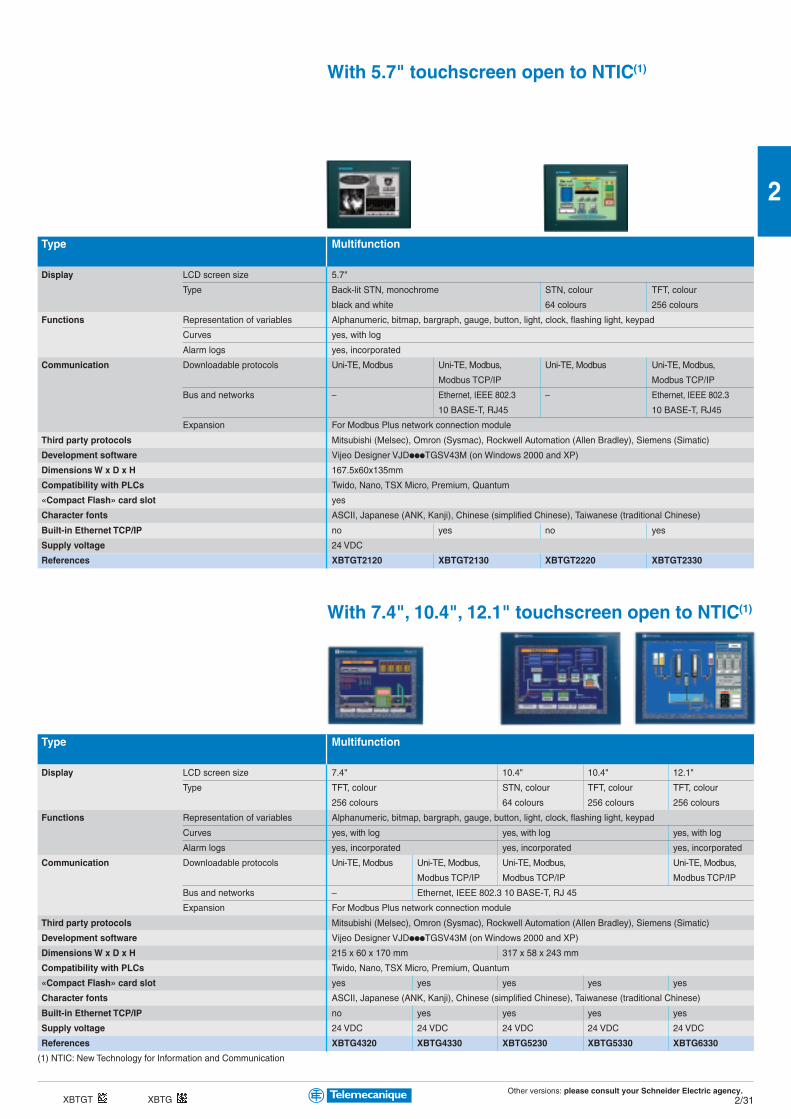
Other versions: please consult your Schneider Electric agency.2/31
2
With 5.7" touchscreen open to NTIC(1)
Type Multifunction
Display LCD screen size 5.7"
Type Back-lit STN, monochrome STN, colour TFT, colour
black and white 64 colours 256 colours
Functions Representation of variables Alphanumeric, bitmap, bargraph, gauge, button, light, clock, flashing light, keypad
Curves yes, with log
Alarm logs yes, incorporated
Communication Downloadable protocols Uni-TE, Modbus Uni-TE, Modbus, Uni-TE, Modbus Uni-TE, Modbus,
Modbus TCP/IP Modbus TCP/IP
Bus and networks – Ethernet, IEEE 802.3 – Ethernet, IEEE 802.3
10 BASE-T, RJ45 10 BASE-T, RJ45
Expansion For Modbus Plus network connection module
Third party protocols Mitsubishi (Melsec), Omron (Sysmac), Rockwell Automation (Allen Bradley), Siemens (Simatic)
Development software Vijeo Designer VJDpppTGSV43M (on Windows 2000 and XP)
Dimensions W x D x H 167.5x60x135mm
Compatibility with PLCs Twido, Nano, TSX Micro, Premium, Quantum
«Compact Flash» card slot yes
Character fonts ASCII, Japanese (ANK, Kanji), Chinese (simplified Chinese), Taiwanese (traditional Chinese)
Built-in Ethernet TCP/IP no yes no yes
Supply voltage 24 VDC
References XBTGT2120 XBTGT2130 XBTGT2220 XBTGT2330
With 7.4", 10.4", 12.1" touchscreen open to NTIC(1)
Type Multifunction
Display LCD screen size 7.4" 10.4" 10.4" 12.1"
Type TFT, colour STN, colour TFT, colour TFT, colour
256 colours 64 colours 256 colours 256 colours
Functions Representation of variables Alphanumeric, bitmap, bargraph, gauge, button, light, clock, flashing light, keypad
Curves yes, with log yes, with log yes, with log
Alarm logs yes, incorporated yes, incorporated yes, incorporated
Communication Downloadable protocols Uni-TE, Modbus Uni-TE, Modbus, Uni-TE, Modbus, Uni-TE, Modbus,
Modbus TCP/IP Modbus TCP/IP Modbus TCP/IP
Bus and networks – Ethernet, IEEE 802.3 10 BASE-T, RJ 45
Expansion For Modbus Plus network connection module
Third party protocols Mitsubishi (Melsec), Omron (Sysmac), Rockwell Automation (Allen Bradley), Siemens (Simatic)
Development software Vijeo Designer VJDpppTGSV43M (on Windows 2000 and XP)
Dimensions W x D x H 215 x 60 x 170 mm 317 x 58 x 243 mm
Compatibility with PLCs Twido, Nano, TSX Micro, Premium, Quantum
«Compact Flash» card slot yes yes yes yes yes
Character fonts ASCII, Japanese (ANK, Kanji), Chinese (simplified Chinese), Taiwanese (traditional Chinese)
Built-in Ethernet TCP/IP no yes yes yes yes
Supply voltage 24 VDC 24 VDC 24 VDC 24 VDC 24 VDC
References XBTG4320 XBTG4330 XBTG5230 XBTG5330 XBTG6330
(1) NTIC: New Technology for Information and Communication
XBTGT XBTG

Other versions: please consult your Schneider Electric agency.2/32
2
Magelis AccessoriesFor display units and terminals
Connection cables PC to Magelis transfer cables2.5 m 2.5 m 2 m 2 m 2 m
Application PC to all XBTN200, PC to all XBT except PC to XBTG / XBTGT1000 PC to
N400 and R400 XBTN200, N400, XBTGT2000
R400 and XBTG
Type of connector RJ45/MiniDin + SUB D 9 SUB D 9/SUB D 25 SUB D 9/MiniDin USB/MiniDin USB/USB
Physical link RS 232C RS 232C TTL TTL
References XBTZ945 (1) XBTZ915 (1) XBTZG915 XBTZG925 XBTZG935
(1) Adaptor SR2CBL06 for linking USB port of PC, to be used in conjunction with connecting cables XBTZ945 and XBTZ915 for connecting display units or terminals
XBTN/R/H/P/E/HM/PM/F.
Connection cables Telemecanique PLC connection cables (2.5 m)
Application XBTGT, XBTN200, N400, All XBT except XBTGT, XBTN200, N400, R400, NU400 to:
R400, NU400 to:
Twido, Nano, Twido, Nano, Quantum Momentum
TSX Micro, Premium TSX Micro, Premium (port 1)
Type of connector RJ45 / MiniDin MiniDin / SUB D 25 SUB D 9 / SUB D 25 RJ45 / SUB D 25
Physical link RS 485 RS 485 RS 232 RS 232
References XBTZ9780 XBTZ968 XBTZ9710 XBTZ9711
Network cards PCMCIA type III card Module
Compatibility XBTF XBTF XBTG
Protocol Modbus Plus Fipway Modbus Plus
References TSXMBP100 TSXFPP20 XBTZGMBP
Memory cards PCMCIA type II «Compact Flash»card card
Compatibility XBTF XBTG / XBTGT (except XBTGT2110)
Capacity 16 Mb 128 Mb 256 Mb 512 Mb
References XBTMEM16 XBTZGM128 XBTZGM256 MPCYN00CFE00N

Other versions: please consult your Schneider Electric agency.2/33
2
Magelis Industrial PCs “all in one”i PC Smart and i PC Compact ranges
Type i PC Smart i PC Compact
Display Size 15" active matrix XGA (1024 x 768)
Type TFT colour LCD (262,144 colours)
Data entry Via touchscreen Via touchscreen
Processor Type VIA VIA Intel Pentium 4 Mobile
Frequency 667 MHz 667 MHz 1.7 GHz
Internal hard disk – ≥ 20 Gb IDE, 2"1/2
RAM memory 256 Mb expandable up to 512 Mb 256 Mb expandable up to 512 Mb (1 memory slot max.)
CD-ROM drive – Yes, 24 x
Expansion slots 2 PCMCIA slots 1 PCI bus slot, 2 PCMCIA slots,
– 1 Compact Flash slot
Ethernet TCP/IP network 1 x 10 BASE-T/100BASE-TX (RJ45)
Operating system Windows XPe integrated Windows 2000 pre-installed and Windows XP Pro
Input/Output ports 2 x USB, 1 x COM1, 1 x COM2, 2 x USB, 1 x COM1, 1 x COM2, 1 x COM3
1 x LPT1 (parallel), 1 x PS/2 keyboard 1 x LPT1 (parallel), 1 x PS/2 keyboard and 1 x PS/2 mouse
on front panel – 1 x USB
Fixing Fixings included with each product for mounting on panel or enclosure door
Dimensions W x D x H 395 x 62 x 294 mm 395 x 100 x 294 mm
Supply voltage 24 VDC 115…230 VAC
References Windows XPe integrated MPCST52NDJ00T – –
Windows 2000 – MPCKT52NAA00N MPCKT55NAA00N
Windows XP Pro – MPCKT52NAX00N MPCKT55NAX00N
Combined offers (bundle pack)
Magelis i PC Compact industrial PCs can be supplied with software packages.
Characteristics identical to standard industrial PCs shown above.
Type i PC Compact
Processor Type VIA Intel Pentium 4M
Applications Vijeo Look Vijeo Look
Pre-installed software Vijeo Look 2.6 RT1024 Vijeo Look 2.6 RT1024 Vijeo Look 2.6 BT1024
References Windows 2000 MPCKT52NAA00A MPCKT55NAA00A MPCKT55NAA00B
Windows XP Pro MPCKT52NAX00A MPCKT55NAX00A MPCKT55NAX00B
Accessories
«Compact Flash» card
Capacity 512 Mb (empty) for i PC Smart or i PC Compact
Reference MPCYN00CFE00N
RAM memory expansion
Capacity 512 Mb SO DIMM for VIA 512 Mb SO DIMM for Pentium 4 Mobile
References MPCYK02RAM512 MPCYK05RAM512
i PC Smart i PC Compact
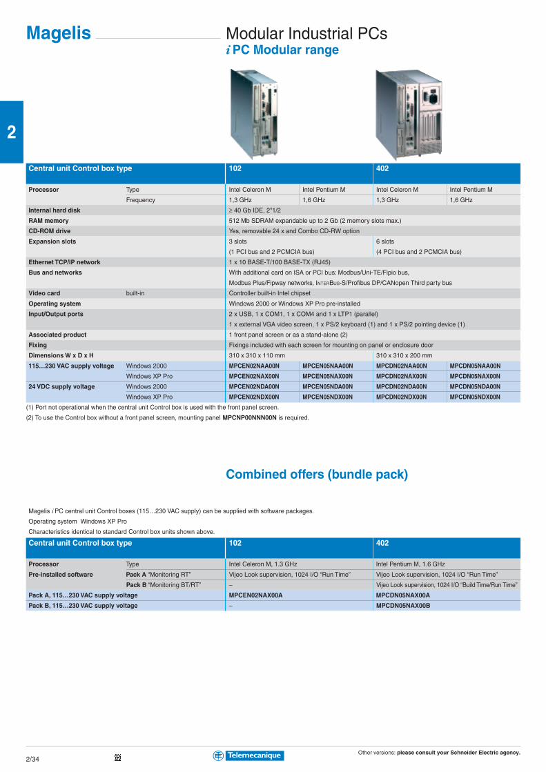
Other versions: please consult your Schneider Electric agency.2/34
2
Magelis Modular Industrial PCsi PC Modular range
Central unit Control box type 102 402
Processor Type Intel Celeron M Intel Pentium M Intel Celeron M Intel Pentium M
Frequency 1,3 GHz 1,6 GHz 1,3 GHz 1,6 GHz
Internal hard disk ≥ 40 Gb IDE, 2"1/2
RAM memory 512 Mb SDRAM expandable up to 2 Gb (2 memory slots max.)
CD-ROM drive Yes, removable 24 x and Combo CD-RW option
Expansion slots 3 slots 6 slots
(1 PCI bus and 2 PCMCIA bus) (4 PCI bus and 2 PCMCIA bus)
Ethernet TCP/IP network 1 x 10 BASE-T/100 BASE-TX (RJ45)
Bus and networks With additional card on ISA or PCI bus: Modbus/Uni-TE/Fipio bus,
Modbus Plus/Fipway networks, INTERBUS-S/Profibus DP/CANopen Third party bus
Video card built-in Controller built-in Intel chipset
Operating system Windows 2000 or Windows XP Pro pre-installed
Input/Output ports 2 x USB, 1 x COM1, 1 x COM4 and 1 x LTP1 (parallel)
1 x external VGA video screen, 1 x PS/2 keyboard (1) and 1 x PS/2 pointing device (1)
Associated product 1 front panel screen or as a stand-alone (2)
Fixing Fixings included with each screen for mounting on panel or enclosure door
Dimensions W x D x H 310 x 310 x 110 mm 310 x 310 x 200 mm
115…230 VAC supply voltage Windows 2000 MPCEN02NAA00N MPCEN05NAA00N MPCDN02NAA00N MPCDN05NAA00N
Windows XP Pro MPCEN02NAX00N MPCEN05NAX00N MPCDN02NAX00N MPCDN05NAX00N
24 VDC supply voltage Windows 2000 MPCEN02NDA00N MPCEN05NDA00N MPCDN02NDA00N MPCDN05NDA00N
Windows XP Pro MPCEN02NDX00N MPCEN05NDX00N MPCDN02NDX00N MPCDN05NDX00N
(1) Port not operational when the central unit Control box is used with the front panel screen.
(2) To use the Control box without a front panel screen, mounting panel MPCNP00NNN00N is required.
Combined offers (bundle pack)
Magelis i PC central unit Control boxes (115…230 VAC supply) can be supplied with software packages.
Operating system Windows XP Pro
Characteristics identical to standard Control box units shown above.
Central unit Control box type 102 402
Processor Type Intel Celeron M, 1.3 GHz Intel Pentium M, 1.6 GHz
Pre-installed software Pack A “Monitoring RT” Vijeo Look supervision, 1024 I/O “Run Time” Vijeo Look supervision, 1024 I/O “Run Time”
Pack B “Monitoring BT/RT” – Vijeo Look supervision, 1024 I/O “Build Time/Run Time”
Pack A, 115…230 VAC supply voltage MPCEN02NAX00A MPCDN05NAX00A
Pack B, 115…230 VAC supply voltage – MPCDN05NAX00B

Other versions: please consult your Schneider Electric agency.2/35
2
Modular Industrial PCsi PC Modular range
Type 15" front panel screen
Display Size 15" active matrix XGA (1024 x 768)
Type Back-lit active matrix TFT colour LCD (262,144 colours)
Data entry Via keyboard Via keyboard and touchscreen Via touchscreen
Keyboard 70 standard IBM keys + 2 x 10 user function keys –
Dimensions W x D x H 480 x 52.7 x 370 mm 480 x 52.7 x 370 mm 460 x 52.7 x 340 mm
Input/Output ports on front panel 1 x IrDA infrared and 1 x PS/2 keyboard/mouse
Associated product 1 central unit Control box or 1 central unit Control box pack (combined offer)
Fixing Fixings included with each screen for mounting on panel or enclosure door
Supply voltage From Control box unit
References MPCNA50NNN20N MPCNB50NNN20N MPCNT50NNN20N
i Display external screen
Separate components
External LCD flat screen, flush mounting 12" SVGA (800 x 600) 15" XGA (1024 x 768)
References 115…230 VAC supply voltage MPCYS20NAN00N MPCYS50NAN00N
24 VDC supply voltage MPCYS20NDN00N MPCYS50NDN00N
Accessories
Separate components for Control box
Qwerty PS/2 keyboard, 101 keys MPCYN00KBD00N
SDRAM memory expansion 512 Mb 1024 Mb
References MPCYDERAM0512 MPCYDERAM1024
Option Combo, DVD drive, CD-RW recorder MPCYN00CDWROM
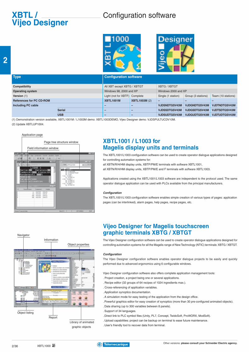
Other versions: please consult your Schneider Electric agency.2/36
2
Configuration softwareXBTL /Vijeo Designer
Type Configuration software
Compatibility All XBT except XBTG / XBTGT XBTG / XBTGT
Operating system Windows 98, 2000 and XP Windows 2000 and XP
Version (1) Light (not for XBTF) Complete Single (1 station) Group (3 stations) Team (10 stations)
References for PC CD-ROM XBTL1001M XBTL1003M (2) – – –
Including PC cable – – VJDSNDTGSV43M VJDGNDTGSV43M VJDTNDTGSV43M
Serial – – VJDSSDTGSV43M VJDGSDTGSV43M VJDTSDTGSV43M
USB – – VJDSUDTGSV43M VJDGUDTGSV43M VJDTUDTGSV43M
(1) Demonstration version available, XBTL1001M / L1003M demo: XBTL1003DEMO, Vijeo Designer demo: VJDSPULTUCDV10M.
(2) Update XBTLUP1004.
XBTL1001 / L1003 forMagelis display units and terminalsThe XBTL1001/L1003 configuration software can be used to create operator dialogue applications designed
for controlling automation systems for:
all XBTN/R/H/HM display units, XBTP/PM/E terminals with software XBTL1001,
all XBTN/R/H/HM display units, XBTP/PM/E and F terminals with software XBTL1003.
Applications created using the XBTL1001/L1003 software are independent to the protocol used. The same
operator dialogue application can be used with PLCs available from the principal manufacturers.
Configuration
The XBTL1001/L1003 configuration software enables simple creation of various types of pages: application
pages (can be interlinked), alarm pages, help pages, recipe pages, etc.
Vijeo Designer for Magelis touchscreengraphic terminals XBTG / XBTGTThe Vijeo Designer configuration software can be used to create operator dialogue applications designed for
controlling automation systems for all the Magelis range of New Technology (NTIC) terminals: XBTG / XBTGT.
Configuration
The Vijeo Designer configuration software enables operator dialogue projects to be easily and quickly
performed due to advanced ergonomics using 6 configurable windows.
Vijeo Designer configuration software also offers complete application management tools:
. Project creation, a project being one or several applications.
. Recipe editor (32 groups of 64 recipes of 1024 ingredients max.).
. Cross-referencing of application variables.
. Application synoptics documentation.
. A simulation mode for easy testing of the application from the design office.
. Powerful graphics editor for easy creation of synoptics (more than 30 pre-configured animated objects).
. Data sharing (up to 300 variables between 8 panels).
. Support of 34 languages.
. Direct link to PLC symbol files (Unity, PL7, Concept, TwidoSoft, ProWORX, ModSoft).
. Upload capabilities: project can be backup on terminal to ease future maintenance.
. User’s friendly tool to recover data from terminal.
Navigator
Information
Object properties
Object listing
Report
Library of animated
graphic objects
XBTL1000
Page tree structure window
Field information window
Application page
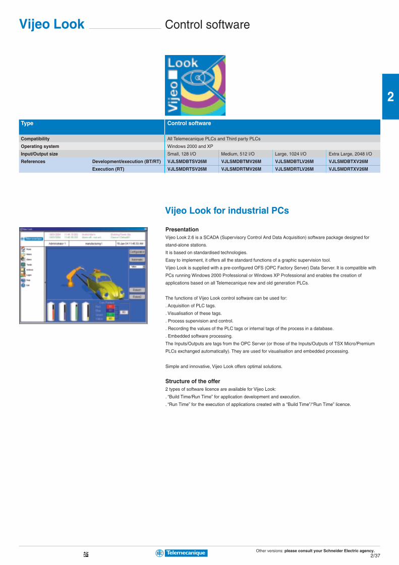
Other versions: please consult your Schneider Electric agency.2/37
2
Control softwareVijeo Look
Type Control software
Compatibility All Telemecanique PLCs and Third party PLCs
Operating system Windows 2000 and XP
Input/Output size Small, 128 I/O Medium, 512 I/O Large, 1024 I/O Extra Large, 2048 I/O
References Development/execution (BT/RT) VJLSMDBTSV26M VJLSMDBTMV26M VJLSMDBTLV26M VJLSMDBTXV26M
Execution (RT) VJLSMDRTSV26M VJLSMDRTMV26M VJLSMDRTLV26M VJLSMDRTXV26M
Vijeo Look for industrial PCs
PresentationVijeo Look 2.6 is a SCADA (Supervisory Control And Data Acquisition) software package designed for
stand-alone stations.
It is based on standardised technologies.
Easy to implement, it offers all the standard functions of a graphic supervision tool.
Vijeo Look is supplied with a pre-configured OFS (OPC Factory Server) Data Server. It is compatible with
PCs running Windows 2000 Professional or Windows XP Professional and enables the creation of
applications based on all Telemecanique new and old generation PLCs.
The functions of Vijeo Look control software can be used for:
. Acquisition of PLC tags.
. Visualisation of these tags.
. Process supervision and control.
. Recording the values of the PLC tags or internal tags of the process in a database.
. Embedded software processing.
The Inputs/Outputs are tags from the OPC Server (or those of the Inputs/Outputs of TSX Micro/Premium
PLCs exchanged automatically). They are used for visualisation and embedded processing.
Simple and innovative, Vijeo Look offers optimal solutions.
Structure of the offer2 types of software licence are available for Vijeo Look:
. “Build Time/Run Time” for application development and execution.
. “Run Time” for the execution of applications created with a “Build Time”/“Run Time” licence.
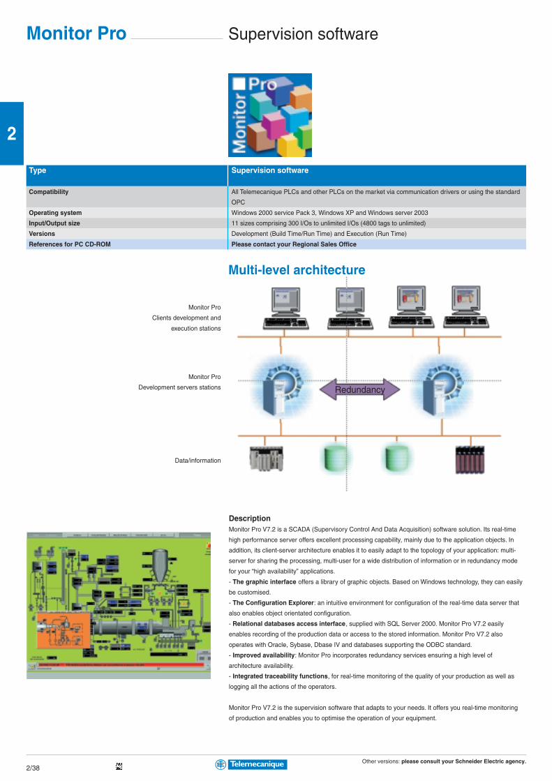
Other versions: please consult your Schneider Electric agency.2/38
2
Monitor Pro Supervision software
Type Supervision software
Compatibility All Telemecanique PLCs and other PLCs on the market via communication drivers or using the standard
OPC
Operating system Windows 2000 service Pack 3, Windows XP and Windows server 2003
Input/Output size 11 sizes comprising 300 I/Os to unlimited I/Os (4800 tags to unlimited)
Versions Development (Build Time/Run Time) and Execution (Run Time)
References for PC CD-ROM Please contact your Regional Sales Office
Multi-level architecture
DescriptionMonitor Pro V7.2 is a SCADA (Supervisory Control And Data Acquisition) software solution. Its real-time
high performance server offers excellent processing capability, mainly due to the application objects. In
addition, its client-server architecture enables it to easily adapt to the topology of your application: multi-
server for sharing the processing, multi-user for a wide distribution of information or in redundancy mode
for your “high availability” applications.
- The graphic interface offers a library of graphic objects. Based on Windows technology, they can easily
be customised.
- The Configuration Explorer: an intuitive environment for configuration of the real-time data server that
also enables object orientated configuration.
- Relational databases access interface, supplied with SQL Server 2000. Monitor Pro V7.2 easily
enables recording of the production data or access to the stored information. Monitor Pro V7.2 also
operates with Oracle, Sybase, Dbase IV and databases supporting the ODBC standard.
- Improved availability: Monitor Pro incorporates redundancy services ensuring a high level of
architecture availability.
- Integrated traceability functions, for real-time monitoring of the quality of your production as well as
logging all the actions of the operators.
Monitor Pro V7.2 is the supervision software that adapts to your needs. It offers you real-time monitoring
of production and enables you to optimise the operation of your equipment.
Monitor Pro
Clients development and
execution stations
Data/information
Monitor Pro
Development servers stations Redundancy
Other versions: please consult your Schneider Electric agency.2/39
2
Embedded Web servers and gatewaysFactoryCast
Implementation software FactoryCast FactoryCast HMI
Compatibility with Telemecanique PLCs TSX Micro, Premium, Quantum Premium, Quantum
Operating system Windows 2000 and XP
Application Configuration of FactoryCast modules Development and implementation of FactoryCast HMI application
References for multilingual PC CD-ROM Included with FactoryCast modules TLXCDFCHMIV1M
FactoryCastRemote “Ready to use” diagnostic functions using simple Internet browser. Secure access to the diagnostics system and application. Numerical or graphical display and adjustment of data. E-mailing. Open to customisation and creation of Web pages for diagnostics suited to your needs. Library of animated graphic objects. SOAP/XML server interface (Web services)
FactoryCast HMIIdentical diagnostic functions as FactoryCast + Core HMI functions embedded in a PLC module:. Real-time database and acquisition of PLC data (1000 variables). Calculations for pre-processing of data. Advanced alarm management with E-mailing. Archiving of data in relational databases (SQL, Oracle, MySQL). Local Data Logging. Recipe management. HTML based Reporting function. A user customizable Web server for creating an interface fully adapted to your needs. Library of animated graphic objects. SOAP/XML client/server interface (Web services)
FactoryCast GatewayNew offer comprising “all in one” Web intelligent gateways integrated in a stand-alone enclosure:. Communications network interfaces and Modbus or Uni-Telway serial links. Remote access function, RAS server, Router. Notification of alarms function by E-mail. A user customizable Web server for creating an interface fully adapted to your needs. Library of animated graphic objects. SOAP/XML client/server interface (Web services)
FactoryCast Web server modules
Automation platform TSX Micro Premium Quantum Modbus Uni-TE
Data rate 10/100 Mbit/s 10 Mbit/s 10/100 Mbit/s 10/100 Mbit/s 10/100 Mbit/s 10/100 Mbit/s
Services Modbus TCP/IP Protocol Yes Yes Yes Yes Yes Yes Yes Yes
Ethernet Uni-TE TCP/IP Protocol Yes Yes Yes Yes – – – Yes
Ethway Protocol – Yes – – – – – –
Serial Protocol Uni-TE – – – – – Modbus Master Uni-Telway slave
Modem Protocol PPP, PAP – – – – – PPP, PAP PPP, PAP
Global Data – – Yes – Yes – – –
I/O Scanning – – Yes – Yes – Yes Yes
Services gateway/RAS Yes – – – – – Yes Yes
Web Standard Web services Yes Yes Yes Yes Yes Yes Yes Yes
server FactoryCast services Yes Yes Yes Yes Yes Yes Yes Yes
FactoryCast HMI services – – – Yes – Yes – –
SOAP/XML Server Web services Yes – Yes Yes Yes Yes Yes Yes
Références TSXETZ510 TSXETY110WS TSXETY5103 TSXWMY100 140NOE77111 140NWM10000 TSXETG1000 TSXETG1010

Aut
omat
ion
Relays and Zelio Logic smart relays
The essentialguideA simplifiedselection guideenabling you toquickly select allthe productsrequired todevelop anautomationsystem... from asmall simplemachineto a complexinstallation.
Ingenious solutions for allyour automation systemapplications
Zelio
Programmable controllersTwido
Twido, ideal for simple installations andsmall machines: standard applicationscomprising 10 to 100 I/O (max. 252 I/O).Compact or modular, Twido offers flexibilityand simplicity.
Automation platforms and distributed I/OsModicon
Perfect suitability for all your applications thanks to a complete offer...from simple relays to automation platforms.
Zelio relay rangeZelio Relay plug-in relays, Zelio Controlcontrol and measurement relays, Zelio Countcounters, Zelio Time timing relays: Theseranges offer compactness and simplicity.
Zelio Logic smart relaysDesigned for management of simpleautomation systems comprising 10 to 40 I/O.Compact or modular, Zelio Logic offersflexibility and simplicity.
Modicon TSX Micro, ideal for machinebuilders. At the heart of the machine, TSXMicro offers compactness, modularityand integration benefits.b CANopen machine bus connectionb Low cost Ethernet connectionb Doubling of memory capacity
Modicon Premium, ideal for manufacturingapplications. Outstanding flexibility fordistributed architectures and integration ofadvanced automation system functions.b New high performance processorsb CANopen machine bus connection, fromentry level
Modicon Quantum, ideal for processapplications. High level of performancefor process control and architectureavailability.b New high performance processorsb Onboard Ethernetb Memory expansion option using PCMCIAb USB connection
Modicon Momentum M1/M1E, ideal fordistributed architectures.Compactness and flexibility for controland I/O distribution on Ethernet.
3/0
With Transparent Ready,Schneider Electric has applied marketstandards to its automation systemarchitectures, making data exchangeeven easier. Smart and simple to use,the Telemecanique software offerensures maximum efficiency in termsof application development andmaintenance, while its highperformance Telemecanique PLCshelp to achieve optimum installationavailability and productivity. Committedto maximising your investment over thelong-term, Schneider Electric makes iteasy for you to develop yourapplications with complete peace ofmind.
Taking you into a new world ofautomation
At the heart of theTelemecaniqueoffer, Unity is thenew generationsoftware andhardwareautomationplatform.
b Open, based onuniversal MicrosoftVisio, VBA and XMLsoftware standards,Unity is designed toallow your tools towork together.
b Smart,Unity provides acommon IECdevelopmentenvironment forModicon Premium,Atrium and Quantumplatforms.With Unity, you canreduce developmentcycles and improvequality by reusingstandardprogrammes.
b Flexible,the new range ofModicon Premium,Atrium and Quantumprocessors offersextended memorycapabilities andgreater executionperformance.
Unity
3/1
3
Contents
Relaysb Zelio Relay - Plug-in relays ........................................... 3/2 and 3/3b Zelio Analog - Analog interface ................................... 3/4 and 3/5b Zelio Control - Control and measurement relays....................... 3/6b Zelio Count - Counters .............................................................. 3/7b Zelio Time - Timing relays ............................................ 3/8 and 3/9b Zelio Logic - Smart relays ........................................ 3/10 and 3/11
Programmable controllers,Automation platformsb Twido - Programmable controllers ............................ 3/12 and 3/13b Modicon TSX Micro - Automation platforms ................ 3/14 to 3/19b Modicon Premium - Automation platforms .................. 3/20 to 3/27b Modicon Quantum - Automation platforms ................. 3/28 to 3/35b Unity - Software ........................................................ 3/36 and 3/37b PL7, Concept, ProWORKS 32 - Software ............... 3/38 and 3/39
Distributed inputs/outputsb Distributed inputs/outputs with processorModicon Momentum ...................................................... 3/40 to 3/43b Distributed inputs/outputs Advantys STB(see Chapter 7 “Interfaces and I/Os”)
Other versions: please consult your Schneider Electric agency.3/2
3
Plug-in relaysInterface and miniature relays
Type of relay Interface relays Miniature relaysRSB RXM
Contact characteristicsThermal current Ith in A (temperature ≤ 55°C) 8 12 16 12 10 6 3
Number of contacts 2 “C/O” 1 “C/O” 1 “C/O” 2 “C/O” 3 “C/O” 4 “C/O” 4 “C/O”
Contact material AgNi AgNi AgNi AgNi AgNi AgNi AgAu
Switching voltage, min. / max. 5 / 250 VAC/DC 12 / 250 VAC/DC
Switching capacity, min. / max. (mA / VA) 5 / 2000 5 / 3000 5 / 4000 10 / 3000 10 / 2500 10 / 1500 2 / 1500
Coil characteristicsAverage consumption, inrush, 0.75 VA / 0.45 W 1.2 VA / 0.9 W
Permissible voltage variation 0.8/0.85…1.1 Un (50 / 60Hz or =) 0.8…1.1 Un (50 / 60Hz or =)
References (1) (1) (1) (2) (2) (2)
Coil supply voltage 6 VDC RSB2A080RD RSB1A120RD RSB1A160RD – – – –
on DC 12 VDC RSB2A080JD RSB1A120JD RSB1A160JD RXM2AB2JD RXM3AB2JD RXM4AB2JD RXM4GB2JD
24 VDC RSB2A080BD RSB1A120BD RSB1A160BD RXM2AB2BD RXM3AB2BD RXM4AB2BD RXM4GB2BD
48 VDC RSB2A080ED RSB1A120ED RSB1A160ED RXM2AB2ED RXM3AB2ED RXM4AB2ED RXM4GB2ED
60 VDC RSB2A080ND RSB1A120ND RSB1A160ND – – – –
110 VDC RSB2A080FD RSB1A120FD RSB1A160FD RXM2AB2FD RXM3AB2ED RXM4AB2ED RXM4GB2ED
Coil supply voltage 24 VAC RSB2A080B7 RSB1A120B7 RSB1A160B7 RXM2AB2B7 RXM3AB2B7 RXM4AB2B7 RXM4GB2B7
on AC 48 VAC RSB2A080E7 RSB1A120E7 RSB1A160E7 RXM2AB2E7 RXM3AB2E7 RXM4AB2E7 RXM4GB2E7
120 VAC RSB2A080F7 RSB1A120F7 RSB1A160F7 RXM2AB2F7 RXM3AB2F7 RXM4AB2F7 RXM4GB2F7
220 VAC RSB2A080M7 RSB1A120M7 RSB1A160M7 – – – –
230 VAC RSB2A080P7 RSB1A120P7 RSB1A160P7 RXM2AB2P7 RXM3AB2P7 RXM4AB2P7 RXM4GB2P7
240 VAC RSB2A080U7 RSB1A120U7 RSB1A160U7 – – – RXM4GB2U7
Sockets for relaysType of socket For interface relays RSB For miniature relays RXMMixed input/output type sockets with location for protection module
– – – RXZE2M114(5) – RXZE2M114 RXZE2M114
– – – RXZE2M114M(5) – RXZE2M114M RXZE2M114M
Separate input/output type sockets with location for protection module
RSZE1S48M RSZE1S35M RSZE1S48M(3) RXZE2S108M RXZE2S111M RXZE2S114M RXZE2S114M
Protection modules
Diode 6…230 VDC RZM040W RXM040W
RC circuit 24…60 VAC RZM041BN7 RXM041BN7
110…240 VAC RZM041FU7 RXM041FU7
Varistor 6…24 VDC or AC RZM021RB (6) RXM021RB
24…60 VDC or AC RZM021BN (6) RXM021BN
110…230 VDC or AC RZM021FP (6) RXM021FP
24 VDC or AC – –
240 VDC or AC – –
Multifunction timer module 24…230 VDC or AC – –
AccessoriesPlastic maintaining clamp RSZR215 RXZR335
Metal maintaining clamp – RXZ400
Label for socket RSZL300 RXZL420 (except RXZE2M114)
Bus jumper 2 poles – RXZS2
DIN rail adapter – RXZE2DA
Panel mounting adapter – RXZE2FA
(1) References for relays without socket, for relays with socket, add the letter S to the end of the selected reference. (Example: RSB2A080B7 becomes RSB2A080B7S).
(2) References for relays with LED, for relays without LED, replace the number 1 in the reference by 2. (Example: RXM2AB2JD becomes RXM2AB1JD)
(3) To use RSB 1A160 pp relay with socket, terminals must be interconnected
Zelio Relay

Other versions: please consult your Schneider Electric agency.3/3
3
Universal and power relays
Universal relays Power relaysRUM RPM RPFCylindrics Faston
10 10 3 10 10 15 15 15 15 30 (4) 30 (4)
2 “C/O” 3 “C/O” 3 “C/O” 2 “C/O” 3 “C/O” 1 “C/O” 2 “C/O” 3 “C/O” 4 “C/O” 2 “N/O” 2 “C/O”
AgNi AgNi AgAu AgNi AgNi AgNi AgNi AgNi AgNi AgSnO2
AgSnO2
12 / 250 VAC/DC 12 / 250 VAC/DC 12 / 250 VAC/DC
10 / 2500 10 / 2500 3 / 750 10 / 2500 10 / 2500 100 / 3750 100 / 3750 100 / 3750 100 / 3750 100 / 7200 100 / 7200
2…3 VA / 1.4 W 0.9 VA / 0.7 W 1.2 VA / 0.9 W 1.5 VA / 1.7 W 1.5 VA / 2 W 4 VA / 1.7 W
(2) (2) – (2) (2) (2) (2) (2) (2) – –
– – – – – – – – – – –
RUMC2AB2JD RUMC3AB2JD – RUMF2AB2JD RUMF3AB2JD RPM12JD RPM22JD RPM32JD RPM42JD RPF2AJD RPF2BJD
RUMC2AB2BD RUMC3AB2BD RUMC3GB2BD RUMF2AB2BD RUMF3AB2BD RPM12BD RPM22BD RPM32BD RPM42BD RPF2ABD RPF2BBD
RUMC2AB2ED RUMC3AB2ED RUMC3GB2ED RUMF2AB2ED RUMF3AB2ED RPM12ED RPM22ED RPM32ED RPM42ED – –
– – – – – – – – – – –
RUMC2AB2FD RUMC3AB2FD – RUMF2AB2FD RUMF3AB2FD RPM12FD RPM22FD RPM32FD RPM42FD RPF2AFD RPF2BFD
RUMC2AB2B7 RUMC3AB2B7 RUMC3GB2B7 RUMF2AB2B7 RUMF3AB2B7 RPM12B7 RPM22B7 RPM32B7 RPM42B7 RPF2AB7 RPF2BB7
RUMC2AB2E7 RUMC3AB2E7 RUMC3GB2E7 RUMF2AB2E7 RUMF3AB2E7 RPM12E7 RPM22E7 RPM32E7 RPM42E7 – –
RUMC2AB2F7 RUMC3AB2F7 RUMC3GB2F7 RUMF2AB2F7 RUMF3AB2F7 RPM12F7 RPM22F7 RPM32F7 RPM42F7 RPF2AF7 RPF2BF7
– – – – – – – – – – –
RUMC2AB2P7 RUMC3AB2P7 RUMC3GB2P7 RUMF2AB2P7 RUMF3AB2P7 RPM12P7 RPM22P7 RPM32P7 RPM42P7 RPF2AP7 RPF2BP7
– – – – – – – – – – –
For universal relays RUM For power relays RPM For power relays RPF
RUZC2M RUZC3M RUZC3M – – RPZF1 RPZF2 RPZF3 RPZF4 –
– – – – – – – – – –
RUZSC2M RUZSC3M RUZSC3M RUZSF3M RUZSF3M – – – – –
1 and 2 poles 3 and 4 poles
RUW240BD RXM040W RUW240BD –
– RXM041BN7 – –
RUW241P7 RXM041FU7 RUW241P7 –
– RXM021RB – –
– RXM021BN – –
– RXM021FP – –
RUW242B7 RUW242B7 – –
RUW242P7 – RUW242P7 –
RUW101MW – RUW101MW –
– – –
RUZC200 RPZF1 (for 1 pole relays) –
RUZL420 – –
RUZS2 – –
– RPZ1DA RXZE2DA RPZ3DA RPZ4DA –
– RPZ1FA RXZE2FA RPZ3FA RPZ4FA –
(4) 30A with 13 mm space between relays; 25 A when relay mounting side by side
(5) Max 10 A operating
(6) With LED
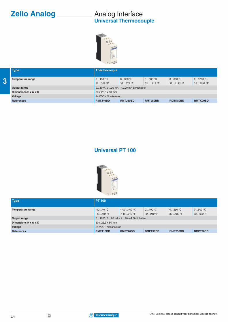
Other versions: please consult your Schneider Electric agency.3/4
3
Analog InterfaceUniversal Thermocouple
Type Thermocouple
Temperature range 0…150 °C 0…300 °C 0…600 °C 0…600 °C 0…1200 °C32…302 °F 32…572 °F 32…1112 °F 32…1112 °F 32…2192 °F
Output range 0…10 V / 0…20 mA - 4…20 mA Switchable
Dimensions H x W x D 80 x 22,5 x 80 mm
Voltage 24 VDC - Non isolated
References RMTJ40BD RMTJ60BD RMTJ80BD RMTK80BD RMTK90BD
Universal PT 100
Type PT 100
Temperature range -40…40 °C -100…100 °C 0…100 °C 0…250 °C 0…500 °C-40…104 °F -148…212 °F 32…212 °F 32…482 °F 32…932 °F
Output range 0…10 V / 0…20 mA - 4…20 mA Switchable
Dimensions H x W x D 80 x 22,5 x 80 mm
Voltage 24 VDC - Non isolated
References RMPT10BD RMPT20BD RMPT30BD RMPT50BD RMPT70BD
Zelio Analog

Other versions: please consult your Schneider Electric agency.3/5
3
Type PT 100
Temperature range -40…40 °C -100…100 °C 0…100 °C 0…250 °C 0…500 °C-40…104 °F -148…212 °F 32…212 °F 32…482 °F 32…932 °F
Output range 0…10 V
Dimensions H x W x D 80 x 22,5 x 80 mm
Voltage 24 VDC - Non isolated
References RMPT13BD RMPT23BD RMPT33BD RMPT53BD RMPT73BD
Universal Analog Converter
Type Analog Converter
Input range 0…10 V or 4…20 mA 0…10 V / -10…+10 V 0…50 V / 0…300 V 0…1,5 A / 0…5 A
0…20 mA 0…500 V 0…15 A
4…20 mA
Output range 0…10 V or 4…20 mA 0…10 V / -10…+10 V 0…10 V 0…10 V or 0…20 mA
0…20 mA 0…20 mA ou 4…20 mA
4…20 mA Switchable 4…20 mA Switchable
Dimensions H x W x D 80 x 22,5 x 80 mm 80 x 45 x 80 mm
Voltage 24 VDC - Non isolated 24 VDC - Isolated 24 VDC - Non isolated 24 VDC - Non isolated
References RMCN22BD RMCL55BD RMCV60BD RMCA61BD
Optimum PT 100

Other versions: please consult your Schneider Electric agency.3/6
3
RelaysControl relays for 3-phase supplies
Function Rotational direction and presence of phases+ Undervoltage + Over and undervoltage + Asymmetry
Adjustable time delay without without 0.1…10 s 0.1…10 s fixed, 0.5 s 0.1…10 s
Supply voltage 220…440V 380…440V 400V 380…440V 380…440V 380…440V
Output 2 C/O 2 C/O 2 C/O 2 C/O 1 C/O 2 C/O
References RM4TG20 RM4TU02 RM4TR34 (1) RM4TR32 (2) RM4TA02 RM4TA32
(1) Relay with fixed voltage thresholds.
(2) Relay with adjustable voltage thresholds.
Current and voltage measurement relays
Function Detection ofover and undercurrent over and undercurrent
Measuring range 3…30 mA 0.3…1.5 A 0.05 …0.5 V 1…10 V 30…300 V 180…270 V
10…100 mA 1…5 A 0.3 …3 V 5…50 V 50…500 V
0.1…1 A 3…15 A 0.5…5 V 10…100 V
Adjustable time delay 0.05…30 s 0.05…30 s 0.05 …30 s 0.05…30 s 0.05…30 s 0.1…10 s
Output 2 C/O 2 C/O 2 C/O 2 C/O 2 C/O 2 C/O
References RM4JA31•• (3) RM4JA32•• (3) RM4UA31•• (3) RM4UA32•• (3) RM4UA33•• (3) RM4UB35
Liquid level control relays
Control relays Empty or fill
Sensitivity scale 5 ... 100 kΩ 0.25 ... 5 kΩ2.5 ... 50 kΩ25 ... 500 kΩ
Time delay without adjustable, 0.1 to 10 s
Output 1 C/O 2 C/O
References RM4LG01• (4) RM4LA32•• (4)
Liquid level control probe type Measuring electrode and 1 simple stainless steel electrodereference electrode in PVC protective casing
Mounting suspended suspended
Maximum operating temperature 100°C 100°CReferences LA9RM201 RM79696043
(4) Basic reference. To be completed with the lettersindicating the required voltage, as shown below:
RM4-LG01 RM4-LA32
Voltage VAC, 50/60 Hz VAC, 50/60 Hz VDC
24 V B B –
24…240 V – MW MW
110…130 V F F –
220…240 V M M –
380…415 V Q Q –
(3) Basic reference. To be completed with the lettersindicating the required voltage, as shown below:
Voltage VAC, 50/60 Hz VDC
24…240 V MW MW
110…130 V F –
220…240 V M –
380…415 V Q –
Zelio Control

Other versions: please consult your Schneider Electric agency.3/7
3
CountersTotalisers
Display Mechanical LCD
Supply voltage 24 VDC Battery
Number of digits displayed 5 6 6 8 8
Counting frequency 20 Hz 10 Hz 25 Hz 25 Hz 7.5 kHz
Type of zero reset Manual Without Manual Without Manual (1)
Front face dimensions, W x H 41.5 x 31 mm 30 x 20 mm 60 x 50 mm 60 x 50 mm 48 x 24 mm
References XBKT50000U10M XBKT60000U00M XBKT60000U10M XBKT80000U00M XBKT81030U33E
(1) With electrical interlocking.
Hour counters
Display Mechanical LCD
Supply voltage 24 VAC 230 VAC Battery
Number of digits / display 7 (99,999.99 h) 7 (99,999.99 h) 8 (999,999.99 h)
Supply frequency 50 Hz 50 Hz Mode: 1/100 hour
Type of zero reset Without Without Manual (1)
Front face dimensions, W x H 48 x 48 mm 48 x 48 mm 48 x 24 mm
References XBKH70000004M XBKH70000002M XBKH81000033E
(1) With electrical interlocking.
Multifunction counters
Display LCD LED
Number of digits displayed 6
Counting frequency 5 kHz
Type of reset Manual, electric and automatic
Front face dimensions, W x H 48 x 48 mm
Preselection number 1 2 1 2
References Supply voltage 24 VDC XBKP61130G30E XBKP61230G30E XBKP62130G30E XBKP62230G30E
115 VAC XBKP61130G31E XBKP61230G31E – –
230 VAC XBKP61130G32E XBKP61230G32E XBKP62130G32E XBKP62230G32E
Zelio Count

Other versions: please consult your Schneider Electric agency.3/8
3
Type of modular timer On-delay Multifunctionwidth 17.5 mm, relay outputExternal control no – –
Supply voltage 24 VDC - 24 ...240 VAC 24 VDC - 24 ...240 VAC 12 ... 240VAC/DC
Timing range 0.1 s…100 h 0.1 s…100 h 0.1 s…10 h 0.1 s…100 h
Output 1 C/O 1 C/O 1 C/O 1 C/O
References RE11RAMU RE11RMMU (1) RE11RMEMU (2) RE11RMMW (1)
(1) Multifunction: On-delay, Off-delay, Totaliser, Symmetrical flashing, Chronometer, Pulse on energisation, Pulse output, Timing after closing/opening of control contact.
(2) Multifunction: On-delay, Off-delay, Totaliser, Symmetrical flashing, Chronometer, Pulse on energisation.
Type of modular timer Asymmetrical Pulse on Off delay Chronometerwidth 17.5 mm, relay output flashing energisationExternal control – – – –
Supply voltage 24 VDC - 24…240 VAC 24 VDC - 24…240 VAC 24 VDC - 24…240 VAC 24 VDC - 24…240 VAC
Timing range 0.1 s…100 h 0.1 s…100 h 0.1 s…100 h 0.1 s…100 h
Output 1 C/O 1 C/O 1 C/O 1 C/O
References RE11RLMU RE11RHMU RE11RCMU RE11RBMU
Type of modular timer On-delay Off-delay Multifunction (3)
width 17.5 mm, solid-state outputSupply voltage 24…240 VAC/DC 24…240 VAC 24…240 VAC
Timing range 0.1 s…100 h 0.1 s…100 h 0.1 s…100 h
Output solid-state solid-state solid-state
References RE11LAMW RE11LCBM RE11LMBM
(3) Multifunction: On-delay, Off-delay, Totaliser, Symmetrical flashing, Chronometer, Pulse on energisation, Pulse output, Timing after closing/opening of control contact.
Panel-mounted relays Timer on-delay Asymmetrical Multifunction (4) Multifunction (5)
flasherPower supply 24…240 VAC/DC
Time range 0,02 s…300 h
Output 2 relay 5 A
Reference RE48ATM12MW RE48ACV12MW RE48AMH13MW (6) RE48AML12MW
(4) Timer on-delay / pulse on energization
(5) Timer on-delay / calibrator / timer off-delay / symmetrical flasher
(6) 1 selectable in instantaneous
Timing relaysModular timers
Zelio Time

Other versions: please consult your Schneider Electric agency.3/9
3
Industrial timers
Type of single function relay On-delay Off-delaywidth 22.5 mm, relay outputExternal control no yes no yes yes
Supply voltage 24 VAC/DC 24 VAC/DC 24...240 VAC/DC 24 VAC/DC 24 VAC/DC
110…240 VAC 42…48 VAC/DC 42…48 VAC/DC 42…48 VAC/DC
110…240 VAC 110…240 VAC 110…240 VAC
Timing range 0.05 s...300 h 0.05 s...300 h 0.05 s...10 mn 0.05 s...300 h 0.05 s…300 h
Output 1 C/O 2 C/O (1) 1 C/O 2 C/O (1) 1 C/O
References RE7TL11BU RE7TP13BU RE7RB11MW RE7RL13BU RE7RM11BU
(1) 1 selectable in instantaneous mode.
Type of relay Single function Multifunctionwidth 22.5 mm, relay output Asymmetrical flashing Pulse on energisation 6 functions (2) 8 functions (3)
External control yes no – –
Supply voltage 24 VAC/DC 24 VAC/DC 24 VAC/DC 24 VAC/DC
42…48 VAC/DC 110…240 VAC 42…48 VAC/DC 110…240 VAC
110…240 VAC 110…240 VAC
Timing range 0.05 s...300 h 0.05 s...300 h 0.05 s…300 h 0.05 s…300 h
Output 1 C/O 1 C/O 1 C/O 2 C/O (4)
References RE7CV11BU RE7PE11BU RE7ML11BU RE7MY13BU
(2) RE7ML11BU functions: On-delay, Off-delay, Pulse on energisation with start on energisation, Pulse on energisation with start on opening of remote control contact, Flashing with
start during the OFF period, Flashing with start during the ON period.
(3) REMY13BU functions: On-delay, Off-delay, Pulse on energisation with start on energisation, Pulse on energisation with start on opening of remote control contact, Flashing with
start during the OFF period, Flashing with start during the ON period, Star-delta starting with double On-delay timing, Star-delta starting with contact for switching to star connection.
(4) 1 selectable in instantaneous mode
Miniature plug-in relays, relay output
Functions
Timing ranges 7 switchable ranges 0.1 s…1 s - 1 s…10 s - 0.1 min…1 min - 1 min…10 min - 0.1 h…1 h - 1 h…10 h - 10 h…100 h
Relay output 4 timed C/O contacts 2 timed C/O contacts
Rated current AC 3 A AC 5 A
Voltages 24 VDC RE XL4TMBD RE XL2TMBD
24 VAC 50/60 Hz RE XL4TMB7 RE XL2TMB7
120 VAC 50/60 Hz RE XL4TMF7 RE XL2TMF7
230 VAC 50/6 0 Hz RE XL4TMP7 RE XL2TMP7
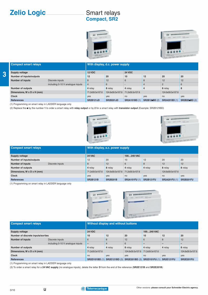
Other versions: please consult your Schneider Electric agency.3/10
3
Smart relaysCompact, SR2
Compact smart relays With display, d.c. power supply
Supply voltage 12 VDC 24 VDC
Number of inputs/outputs 12 20 10 12 20 20
Number of inputs Discrete inputs 8 12 6 8 12 12
including 0-10 V analogue inputs 4 6 - 4 2 6
Number of outputs 4 relay 8 relay 4 relay 4 8 relay 8
Dimensions, W x D x H (mm) 71.2x59.5x107.6 124.6x59.5x107.6 71.2x59.5x107.6 124.6x59.5x107.6
Clock yes yes no yes no yes
References SR2B121JD SR2B201JD SR2A101BD (1) SR2B12pppppBD (2) SR2A201BD (1) SR2B20pppppBD (2)
(1) Programming on smart relay in LADDER language only
(2) Replace the ppppp by the number 1 to order a smart relay with relay output or by 2 for a smart relay with transistor output (Example: SR2B121BD)
Compact smart relays With display, a.c. power supply
Supply voltage 24 VAC 100…240 VAC
Number of inputs/outputs 12 20 10 12 20 20
Number of inputs Discrete inputs 8 12 6 8 12 12
Number of outputs 4 relay 8 relay 4 relay 4 relay 8 relay 8 relay
Dimensions, W x D x H (mm) 71.2x59.5x107.6 124.6x59.5x107.6 71.2x59.5x107.6 124.6x59.5x107.6
Clock yes yes no yes no yes
References SR2B121B SR2B201B SR2A101FU (1) SR2B121FU SR2A201FU (1) SR2B201FU
(1) Programming on smart relay in LADDER language only
Compact smart relays Without display and without buttons
Supply voltage 24 VDC 100…240 VAC
Number of discrete inputs/sorties 10 12 20 10 12 20
Number of inputs Discrete inputs 6 8 12 6 8 12
including 0-10 V analogue inputs – 4 6 – – –
Number of outputs 4 relay 4 relay 8 relay 4 relay 4 relay 8 relay
Dimensions, W x D x H (mm) 71.2x59.5x107.6 124.6x59.5x107.6 71.2x59.5x107.6 124.6x59.5x107.6
Clock no yes yes no yes yes
References SR2D101BD (1) SR2E121BD (3) SR2E201BD (3) SR2D101FU (1) SR2E121FU SR2E201FU
(1) Programming on smart relay in LADDER language only
(3) To order a smart relay for a 24 VAC supply (no analogue inputs), delete the letter D from the end of the reference (SR2E121B and SR2E201B)
Zelio Logic
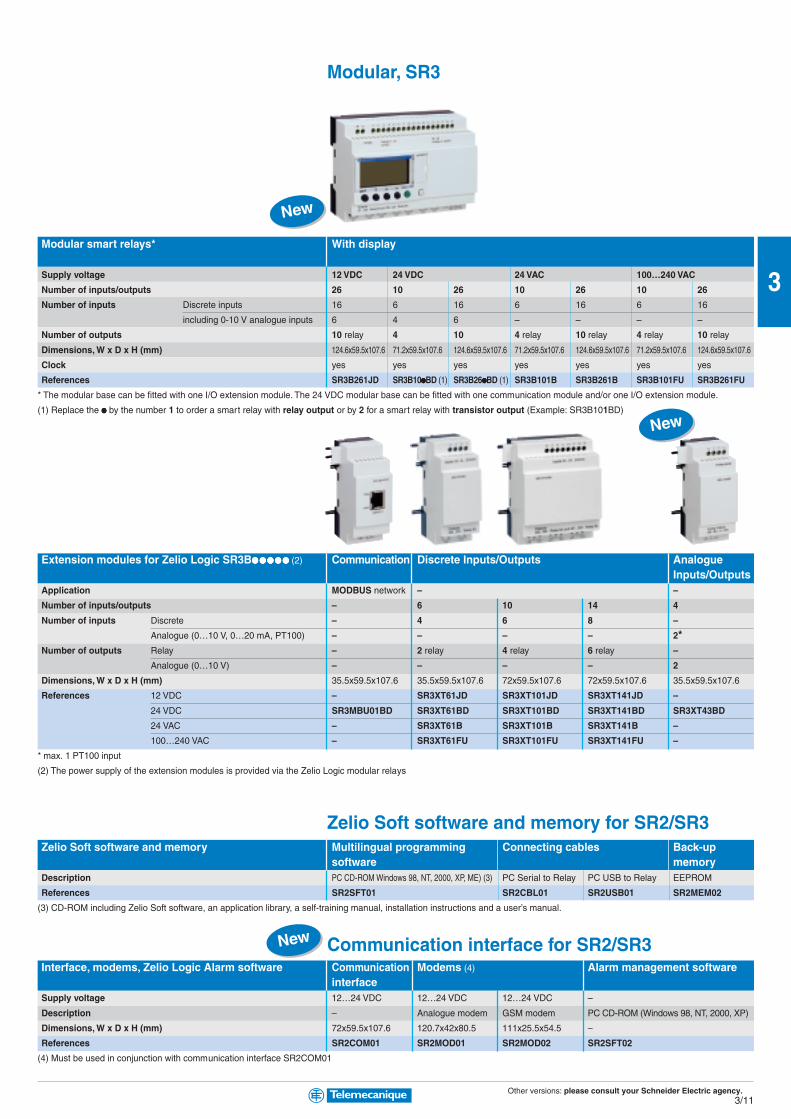
Other versions: please consult your Schneider Electric agency.3/11
3
Modular, SR3
Modular smart relays* With display
Supply voltage 12 VDC 24 VDC 24 VAC 100…240 VAC
Number of inputs/outputs 26 10 26 10 26 10 26
Number of inputs Discrete inputs 16 6 16 6 16 6 16
including 0-10 V analogue inputs 6 4 6 – – – –
Number of outputs 10 relay 4 10 4 relay 10 relay 4 relay 10 relay
Dimensions, W x D x H (mm) 124.6x59.5x107.6 71.2x59.5x107.6 124.6x59.5x107.6 71.2x59.5x107.6 124.6x59.5x107.6 71.2x59.5x107.6 124.6x59.5x107.6
Clock yes yes yes yes yes yes yes
References SR3B261JD SR3B10pppppBD (1) SR3B26pppppBD (1) SR3B101B SR3B261B SR3B101FU SR3B261FU
* The modular base can be fitted with one I/O extension module. The 24 VDC modular base can be fitted with one communication module and/or one I/O extension module.
(1) Replace the ppppp by the number 1 to order a smart relay with relay output or by 2 for a smart relay with transistor output (Example: SR3B101BD)
Extension modules for Zelio Logic SR3Bppppppppppppppppppppppppp (2) Communication Discrete Inputs/Outputs AnalogueInputs/Outputs
Application MODBUS network – –
Number of inputs/outputs – 6 10 14 4
Number of inputs Discrete – 4 6 8 –
Analogue (0…10 V, 0…20 mA, PT100) – – – – 2*Number of outputs Relay – 2 relay 4 relay 6 relay –
Analogue (0…10 V) – – – – 2
Dimensions, W x D x H (mm) 35.5x59.5x107.6 35.5x59.5x107.6 72x59.5x107.6 72x59.5x107.6 35.5x59.5x107.6
References 12 VDC – SR3XT61JD SR3XT101JD SR3XT141JD –
24 VDC SR3MBU01BD SR3XT61BD SR3XT101BD SR3XT141BD SR3XT43BD
24 VAC – SR3XT61B SR3XT101B SR3XT141B –
100…240 VAC – SR3XT61FU SR3XT101FU SR3XT141FU –
* max. 1 PT100 input
(2) The power supply of the extension modules is provided via the Zelio Logic modular relays
Zelio Soft software and memory for SR2/SR3Zelio Soft software and memory Multilingual programming Connecting cables Back-up
software memoryDescription PC CD-ROM Windows 98, NT, 2000, XP, ME) (3) PC Serial to Relay PC USB to Relay EEPROM
References SR2SFT01 SR2CBL01 SR2USB01 SR2MEM02
(3) CD-ROM including Zelio Soft software, an application library, a self-training manual, installation instructions and a user’s manual.
Communication interface for SR2/SR3Interface, modems, Zelio Logic Alarm software Communication Modems (4) Alarm management software
interfaceSupply voltage 12…24 VDC 12…24 VDC 12…24 VDC –
Description – Analogue modem GSM modem PC CD-ROM (Windows 98, NT, 2000, XP)
Dimensions, W x D x H (mm) 72x59.5x107.6 120.7x42x80.5 111x25.5x54.5 –
References SR2COM01 SR2MOD01 SR2MOD02 SR2SFT02
(4) Must be used in conjunction with communication interface SR2COM01
New
New
New
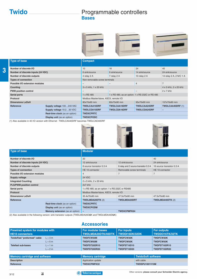
Other versions: please consult your Schneider Electric agency.3/12
3
Programmable controllersBases
Type of base Compact
Number of discrete I/O 10 16 24 40
Number of discrete inputs (24 VDC) 6 sink/source 9 sink/source 14 sink/source 24 sink/source
Number of discrete outputs 4 relay 2 A 7 relay 2 A 10 relay 2 A 14 relay 2 A, 2 N/C 1 A
Types of connection Non-removable screw terminals
Possible I/O extension modules – – 4 7
Counting 3 x 5 kHz, 1 x 20 kHz 4 x 5 kHz, 2 x 20 kHz
PWM position control – – – 2 x 7 kHz
Serial ports 1 x RS 485 1 x RS 485; as an option: 1 x RS 232C or RS 485
Protocol Modbus Master/slave, ASCII, remote I/O
Dimensions LxDxH 80x70x90 mm 80x70x90 mm 95x70x90 mm 157x70x90 mm
Reference Supply voltage 100…240 VAC TWDLCAA10DRF TWDLCAA16DRF TWDLCAA24DRF TWDLCAA40DRF (1)
Supply voltage 19.2…30 VDC TWDLCDA10DRF TWDLCDA16DRF TWDLCDA24DRF –
Real-time clock (as an option) TWDXCPRTC
Display unit (as an option) TWDXCPODC
(1) Also available in 40 I/O version with Ethernet : TWDLCAA40DRF becomes TWDLCAE40DRF
Type of base Modular
Number of discrete I/O 20 40
Number of discrete inputs (24 VDC) 12 sink/source 12 sink/source 24 sink/source
Number of discrete outputs 8 source transistor 0.3 A 6 relay and 2 source transistor 0.3 A 16 source transistor 0.3 A
Types of connection HE 10 connector Removable screw terminals HE 10 connector
Possible I/O extension modules 4 7 7
Supply voltage 24 VDC
Integrated Counting 2 x 5 kHz, 2 x 20 kHz
PLS/PWM position control 2x7 kHz
Serial ports 1 x RS 485; as an option: 1 x RS 232C or RS485
Protocol Modbus Master/slave, ASCII, remote I/O
Dimensions LxDxH 35.4x70x90 mm 47.5x70x90 mm 47.5x70x90 mm
Reference TWDLMDA20DTK (2) TWDLMDA20DRT TWDLMDA40DTK (2)
Real-time clock (as an option) TWDXCPRTC
Display unit (as an option) TWDXCPODM
Memory extension (as an option) – TWDXCPMFK64
(2) Also available in the following version: sink transistor outputs (TWDLMDA20DUK and TWDLMDA40DUK)
AccessoriesPrewired system for modules with For modular bases For inputs For outputsHE10 connectors TWDLMDA20DTK/40DTK TWDDI16DK/32DK TWDDO16TK/32TK TwidoFast “preformed” cable L = 3 m TWDFCW30M TWDFCW30K TWDFCW30K
L = 5 m TWDFCW50M TWDFCW50K TWDFCW50K
Telefast sub-bases L = 1 m TWDFST20DR10 TWDFST16D10 TWDFST16DR10
L = 2 m TWDFST20DR20 TWDFST16D20 TWDFST16DR20
Memory cartridge and software Memory cartridge TwidoSoft softwareDescription Application update with cable
Reference TWDXCPMFK32 TWDSPU1001V10M
Twido

Other versions: please consult your Schneider Electric agency.3/13
3
I/O modules
Type of module Analog
Number of I/O 2 inputs 4 inputs 8 inputs 1 output 2 outputs 2 inputs/1 output
Connection Removable screw terminals
Inputs Range 0…10 V (1) – 0…10 V (1) Type K, J, T thermocouples
4…20 mA (2) 4…20 mA (2) 3-wire Pt 100 thermal probe
Resolution 12 bits (4096 points) – 12 bits (4096 points)
Outputs Range – 0…10 V ± 10 V 0…10 V
4…20 mA 4…20 mA
Résolution – 12 bits 11 bits + sign 12 bits
Measuring accuracy 0.2 % FS –
Supply voltage 24 VDC
Dimensions LxDxH 23.5 x 70 x 90 mm
Reference TWDAMI2HT TWDAMI4LT TWDAMI8HT TWDAMO1HT TWDAVO2HT TWDAMM3HT TWDALM3LT
(1) Non differential
(2) Differential
Type of module Discrete AS-InterfaceMaster
Number of discrete I/O 8 4 inputs/4 outputs 16 16 32 2 modules (4)
Logical input Sink Sink/Source –
Connections Removable screw terminals HE 10 connectors Removable screw terminals
Reference Inputs 24 VDC TWDDDI8DT TWDDMM8DRT TWDDDI16DT TWDDDI16DK TWDDDI32DK –
Inputs 120 V TWDDAI8DT – – – – –
Relay outputs 2 A TWDDRA8RT TWDDMM8DRT TWDDRA16RT – – –
Source transistor outputs 0.1 A TWDDDO8TT (3) – – TWDDDO16TK (3) TWDDDO32TK (3) TWDNOI10M3
(3) Also available in the following version: sink transistor outputs, (TWDDDO8UT, TWDDDO16UK and TWDDDO32UK)
(4) 2 modules max. 62 discrete slaves max. 7 analog slaves max. AS-Interface/M3, V 2.11 (S.7.4 profile not supported)
Communication modules
Type of module CANopen Serial interface module Serial interface adaptor EthernetExpansion Interface
Physical layer (non isolated) – RS 232C RS 485 RS 232C RS 485 –
Connections Screw terminals Mini-DIN connector Screw terminals Mini-DIN connector Screw terminals RJ45
Protocol – Modbus Master/slave, ASCII, remote I/O –
Compatibility with Twido base Base Modular base TWDLMDA Compact base TWDLCAA16/24DRF All
24 or Modular base via the integrated model
40 I/O display module TWDXCPODM
Reference TWDNCO1M TWDNOZ232D TWDNOZ485D(5) TWDNOZ485T TWDNAC232D TWDNAC485D TWDNAC485T 499TWD01100
(5) Screw terminals available : TWDNpZ485D becomes TWDNpZ485T

Other versions: please consult your Schneider Electric agency.3/14
3
Platform of automatismBasic configurations
Type of processor TSX 3705 TSX 3708 TSX 3710
Power supply 110…240 VAC 24 VDC
Number of slots Standard 2 (1 available) 3 (1 available) 2 (1 available)
On extension – – 2
Number of integrated discrete I/O modules 1 (16 I, 12 Q) 2 (32 I, 24 Q) 1 (16 I, 12 Q) 1 (16 I, 12 Q)
Number of integrated analog I/O channels – – – –
Type of integrated I/O I: 24 VDC, Q: relay I: 24 VDC, Q: relay I: 24 VDC, Q: sol.st. 0.5 A I: 24 VDC, Q: relay
Application-specific modules (counter, position control) 2 half-size 2 half-size
Bus AS-Interface cabling system – 1 half-size
CANopen machine bus – –
Fipio fieldbus – –
Networks Modbus Plus, Fipway – –
Ethernet TCP/IP – 1 external module
Memory capacity Integrated 11 K words 14 K words
With PCMCIA extension – –
Execution time Boolean 0.25 µs 0.25 µsfor one instruction
Numerical 4.81 µs 4.81 µs
Rack dimensions (WxDxH) 170,3 x 132,5 x 151 mm 230 x 132,5 x 151 mm 170,3 x 132,5 x 151 mm
Reference With screw terminals TSX3705028DR1 TSX3708056DR1 TSX3710128DT1 TSX3710128DR1
With HE 10 connector (1) – – TSX3710128DTK1 –
(1) For use with Advantys Telefast ABE7 wiring system
(2) Basic configuration provided without I/O modules
Memory extension
Type of PCMCIA card for TSX 3721/22 Application
Technology SRAM Flash EPROM Backup
Memory size (3) 32 K words TSXMRPP128K TSXMFPP128K TSXMFPB096K
32 K words/128 K words TSXMRPP348K TSXMCPC224K –
64 K words TSXMRPP224K TSXMFPP224K –
64 K words/128 K words TSXMRPP384K TSXMCPC224K –
128 K words TSXMRPC448K TSXMFPP384K –
128 K words/128 K words TSXMRPC768K – –
(3) The 1st value corresponds to the size of the application area, the second to the size of the area for data storage (recipes, production data, etc).
Connection accessories: See www.telemecanique.com
Modicon TSX Micro

Other versions: please consult your Schneider Electric agency.3/15
3
TSX 3710 TSX 3721 TSX 3722
24 VDC 110…240 VAC 24 VDC 110…240 VAC 24 VDC 110…240 VAC
2 (1 available) 3 (3 available) 3 (3 available)
2 2 2
2 (32 I, 32 Q) 1 (16 I, 12 Q) 1 (16 I, 12 Q) – –
– – – – 1 (8 I, 1 Q)
I: 24 VDC, Q: sol. st. 0.1 A I: 115 VAC, Q: relay I: 24 VDC, Q: relay – I: 0…10 V or 0/4…20 mA, Q: 0…10 V
2 half-size 4 half-size 4 half-size (2 integrated channels)
1 half-size 1 half-size 1 half-size
– 1 PCMCIA card 1 PCMCIA card
– 1 PCMCIA card 1 PCMCIA card
– 1 PCMCIA card 1 PCMCIA card
1 external module 1 external module 1 external module
14 K words 20 K words 20 K words
– 128 K words + 128 K words for file storage 128 K words + 128 K words for file storage
0.25 µs 0.13 µs (0.19 µs with PCMCIA) 0.13 µs (0.19 µs with PCMCIA)
4.81 µs 4.50 µs 4.50 µs
170,3 x 132,5 x 151 mm 230 x 132,5 x 151 mm
– TSX3710028AR1 TSX3710028DR1 TSX3721101 (2) TSX3721001 (2) TSX3722101 (2) TSX3722001 (2)
TSX3710164DTK1 – –
Mini extension rack
Type of rack 2 slots(4 positions)
For use with TSX3710/21/22
Rack dimensions (WxDxH) 112,5 x 132,5 x 151 mm
Reference TSXRKZ2
Process power supplies see chapter 6 “Power supply”
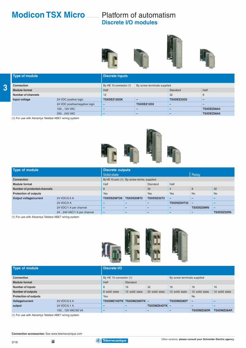
Other versions: please consult your Schneider Electric agency.3/16
3
Platform of automatismDiscrete I/O modules
Type of module Discrete inputs
Connection By HE 10 connector (1) By screw terminals supplied
Module format Half Standard Half
Number of channels 12 32 8
Input voltage 24 VDC positive logic TSXDEZ12D2K – TSXDEZ32D2 –
24 VDC positive/negative logic – TSXDEZ12D2 – –
100…120 VAC – – – TSXDEZ08A4
200…240 VAC – – – TSXDEZ08A5
(1) For use with Advantys Telefast ABE7 wiring system
Type of module Discrete outputsSolid state Relay
Connection By HE 10 conn. (1) By screw terms. supplied
Module format Half Standard Half
Number of protected channels 8 32 4 8 32
Protection of outputs Yes Yes Yes No No
Output voltage/current 24 VDC/0.5 A TSXDSZ08T2K TSXDSZ08T2 TSXDSZ32T2 – – –
24 VDC/2 A – – – TSXDSZ04T22 – –
24 VDC/1 A per channel – – – – TSXDSZ08R5 –
24…240 VAC/1 A per channel – – – – – TSXDSZ32R5
(1) For use with Advantys Telefast ABE7 wiring system
Type of module Discrete I/O
Connection By HE 10 connector (1) By screw terminals supplied
Module format Half Standard
Number of inputs 8 16 32 16 16 16
Number of outputs 8 solid state 12 solid state 32 solid state 12 solid state 12 solid state 12 solid state
Protection of outputs Yes No
Voltage/current 24 VDC/0.5 A TSXDMZ16DTK TSXDMZ28DTK – TSXDMZ28DT – –
output 24 VDC/0.1 A – – TSXDMZ64DTK – – –
100…120 VAC/50 VA – – – – TSXDMZ28DR TSXDMZ28AR
(1) For use with Advantys Telefast ABE7 wiring system
Connection accessories: See www.telemecanique.com
Modicon TSX Micro

Other versions: please consult your Schneider Electric agency.3/17
3
Analog I/O modules
Type of module Analog inputsHigh level with common point High level isolated
Connection By screw terminals supplied By screw terminals supplied
Number of channels 8 4
Resolution 11 bits + sign 12 bits 16 bits
Input signal ± 10 V, 0…10 V 0…20 mA, 4…20 mA (1)
Reference TSXAEZ801 TSXAEZ802 TSXAEZ414
(1) ± 10 V, 0…10 V, 0…5 V, 1…5 V, 0…20 mA, 4…20 mA, B, E, J, K, L, N, R, S, T, U, Pt 100, Ni 1000 (2 or 4-wire), thermal probe, thermocouple
Type de module Analog outputsWith common point
Connection By screw terminals supplied By screw terminals supplied
Number of channels 4 2
Resolution 11 bits + sign 11 bits + sign or 12 bits
Input signal ± 10 V, 0…10 V ± 10 V, 0…20 mA, 4…20 mA
Reference TSXASZ401 TSXASZ200
Type of module Analog I/O Analog I/OIntegrated High level with common point
Connection By 15-way SUB-D connector not supplied By screw terminals supplied
Number of inputs 8 4
Number of outputs 1 2
Resolution 8 bits 11 bits + sign or 12 bits
I/O signal 0…10 V, 0…20 mA, 4…20 mA ± 10 V, 0…10 V, 0…20 mA, 4…20 mA
Reference TSX3722 (2) TSXAMZ600
(2) References: see pages 3/16 and 3/17, TSX3722 basic configuration
Connection accessories: See www.telemecanique.com
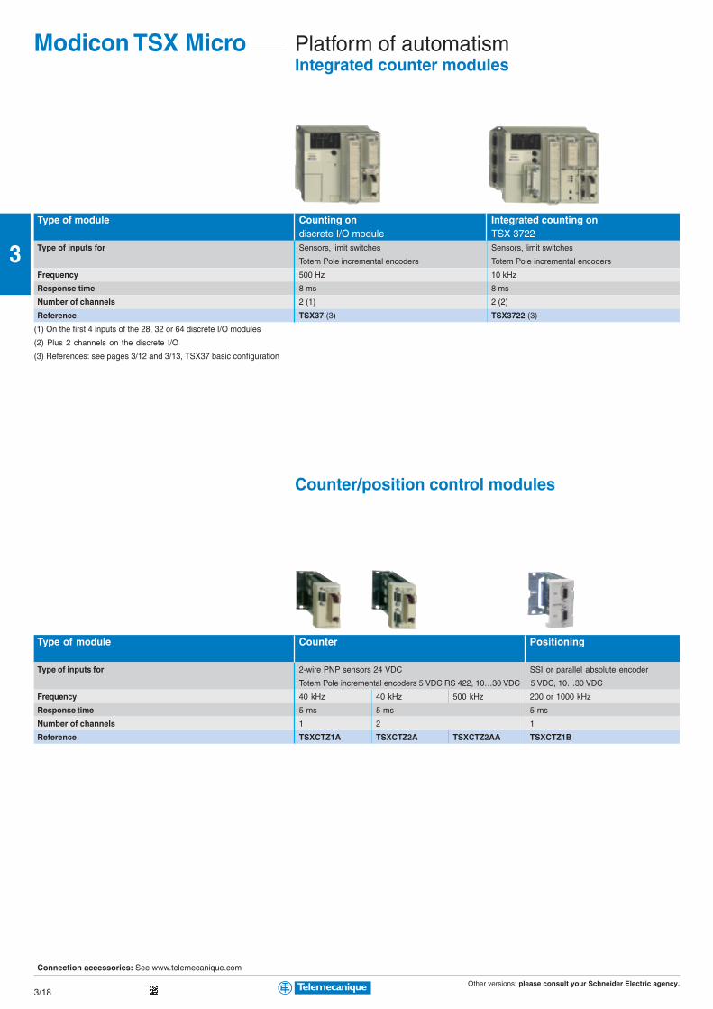
Other versions: please consult your Schneider Electric agency.3/18
3
Platform of automatismIntegrated counter modules
Type of module Counting on Integrated counting ondiscrete I/O module TSX 3722
Type of inputs for Sensors, limit switches Sensors, limit switches
Totem Pole incremental encoders Totem Pole incremental encoders
Frequency 500 Hz 10 kHz
Response time 8 ms 8 ms
Number of channels 2 (1) 2 (2)
Reference TSX37 (3) TSX3722 (3)
(1) On the first 4 inputs of the 28, 32 or 64 discrete I/O modules
(2) Plus 2 channels on the discrete I/O
(3) References: see pages 3/12 and 3/13, TSX37 basic configuration
Counter/position control modules
Type of module Counter Positioning
Type of inputs for 2-wire PNP sensors 24 VDC SSI or parallel absolute encoder
Totem Pole incremental encoders 5 VDC RS 422, 10…30 VDC 5 VDC, 10…30 VDC
Frequency 40 kHz 40 kHz 500 kHz 200 or 1000 kHz
Response time 5 ms 5 ms 5 ms
Number of channels 1 2 1
Reference TSXCTZ1A TSXCTZ2A TSXCTZ2AA TSXCTZ1B
Connection accessories: See www.telemecanique.com
Modicon TSX Micro
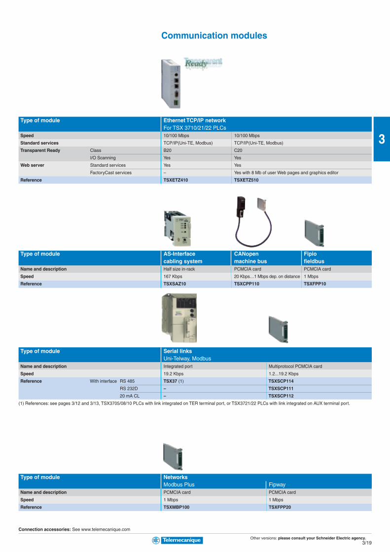
Other versions: please consult your Schneider Electric agency.3/19
3
Communication modules
Type of module Ethernet TCP/IP networkFor TSX 3710/21/22 PLCs
Speed 10/100 Mbps 10/100 Mbps
Standard services TCP/IP(Uni-TE, Modbus) TCP/IP(Uni-TE, Modbus)
Transparent Ready Class B20 C20
I/O Scanning Yes Yes
Web server Standard services Yes Yes
FactoryCast services – Yes with 8 Mb of user Web pages and graphics editor
Reference TSXETZ410 TSXETZ510
Type of module AS-Interface CANopen Fipiocabling system machine bus fieldbus
Name and description Half size in-rack PCMCIA card PCMCIA card
Speed 167 Kbps 20 Kbps…1 Mbps dep. on distance 1 Mbps
Reference TSXSAZ10 TSXCPP110 TSXFPP10
Type of module Serial linksUni-Telway, Modbus
Name and description Integrated port Multiprotocol PCMCIA card
Speed 19.2 Kbps 1.2...19.2 Kbps
Reference With interface RS 485 TSX37 (1) TSXSCP114
RS 232D – TSXSCP111
20 mA CL – TSXSCP112
(1) References: see pages 3/12 and 3/13, TSX3705/08/10 PLCs with link integrated on TER terminal port, or TSX3721/22 PLCs with link integrated on AUX terminal port.
Type of module NetworksModbus Plus Fipway
Name and description PCMCIA card PCMCIA card
Speed 1 Mbps 1 Mbps
Reference TSXMBP100 TSXFPP20
Connection accessories: See www.telemecanique.com

Other versions: please consult your Schneider Electric agency.3/20
3
Platform of automatismProcessors under Unity Pro software
Type of processor TSX 57C configuration TSX 5700 TSX 5710 TSX 57201 rack max. 1 rack max. 4 racks max. 16 racks max.
Number of I/O Discrete 192 256 512 1024
in racks Analog 12 12 24 80
Integrated process control No / Yes No / Yes No / Yes 30 loops / Yes
Application-specific channels (counter, position control, weighing) 4 4 8 24
Bus AS-Interface cabling system 1 1 2 4
CANopen machine bus 1 (integrated) 1 (integrated) 1 1
INTERBUS, Profibus DP fieldbus – – 1 1
Networks (Ethernet, Modbus Plus, Fipway) 1 1 1 2 (7)
Memory capacity Without PCMCIA extension 96 Kb data/prog 96 Kb data/prog 96 Kb data/prog. 160/192 Kb data/prog. (1)
With PCMCIA extension 96 Kb data/128 Kb prog. 96 Kb data/128 Kb prog. 96 Kb data/224 Kb prog. 160/192 Kb data (1)/768 Kb prog.
Execution time Boolean 0.19 µs 0.19 µs 0.19 µs 0.19 µs
for one instruction On word or arithmetic 0.25 µs 0.25 µs 0.25 µs 0.25 µs
Reference Without integrated port – – TSXP57104M TSXP57204M
Integrated Ethernet – – TSXP571634M TSXP572634M
Integrated CANopen TSXP57Cppppp0244M (2) TSXP570244M – –
Integrated Fipio – – TSXP57154M TSXP57254M
(1) The second value corresponds to the integrated memory capacity when the processor is equipped with a Fipio manager integrated link
(2) 24 VDC version : TSXP57CD0244M, 100...240 VAC version : TSXP57CA0244M
(3) Processor with double format
(4) PC format card on PCI bus
Processors under PL7 software
Type of processor TSX 5710 TSX 57204 racks max. 16 racks max.
Number of I/O Discrete 512 1024
in racks Analog 24 80
Integrated process control No 30 loops
Application-specific channels (counter, position control, weighing) 8 24
Bus AS-Interface cabling system 2 4
CANopen machine bus 1 (with TSXP57103M) 1
INTERBUS, Profibus DP fieldbus – 1
Networks (Ethernet, Modbus Plus, Fipway) 1 1
Memory capacity Without PCMCIA extension 32 K words data/prog. 48 K words data/prog. (5)
With PCMCIA extension 32 K words data/64 K words prog. 32 K words data (5)/160 K words prog.
Execution time Boolean 0.50 µs 0.19 µs
for one instruction On word or arithmetic 0.62 µs 0.25 µs
Reference Without integrated port TSXP57103M TSXP57203M
Integrated Ethernet – TSXP572623M
Integrated Fipio TSXP57153M TSXP57253M
Integrated Ethernet and Fipio – TSXP572823M
(5) The second value corresponds to the processor with integrated Fipio bus manager link.(6) PC format card for ISA bus.(7) Unity Pro V2.3 min.
Modicon Premium

Other versions: please consult your Schneider Electric agency.3/21
3
Atrium slot-PLCsunder Unity Pro software
TSX 5730 TSX 5740 TSX 5750 PCI 5720 PCI 573016 racks max. 16 racks max. 16 racks max. 16 racks max. 16 racks max.1024 2040 2040 1024 1024
128 256 512 80 128
45 loops / Yes 60 loops / Yes 90 loops / Yes 30 loops / Yes 45 loops / Yes
32 64 64 24 32
8 8 8 4 8
1 1 1 1 1
3 4 5 1 3
3 4 4 3 (7) 4
192/208 Kb data/prog. (1) 320 Kb data/prog. 640 Kb data/prog. 160 Kb data/prog. (1) 208 Kb data/prog. (1)
192/208 Kb data (1)/1,75 Mb prog. 440 Kb data/2 Mb prog. 896 Kb data/7 Mb prog. 160 Kb data/768 Kb prog. 208 Kb data (1)/1,75 Mb prog.
0.12 µs 0.06 µs 0.037 µs 0.19 µs 0.12 µs
0.17 µs 0.07 µs 0.045 µs 0.25 µs 0.17 µs
TSXP57304M – – TSXPCI57204M (4) –
TSXP573634M TSXP574634M TSXP575634M – –
– – – – –
TSXP57354M TSXP57454M TSXP57554M – TSXPCI57354M (4)
Atrium slot-PLCsunder PL7 software
TSX 5730 TSX 5740 PCX 5720 PCX 573016 racks max. 16 racks max. 16 racks max. 16 racks max.1024 2048 1024 1024
128 256 80 128
45 loops 60 loops 30 loops 45 loops
32 64 24 32
8 8 4 8
1 1 1 1
2 2 1 2
3 4 1 3
64/80 K words data/prog. (5) 96 K words data/prog. 48 K words data/prog. 80 K words data/prog.
80/96 K words data (5)/384 K words prog. 176 K words data/992 K words prog. (8) 48 K words data/160 K words prog. 96 K words data/384 K words prog.
0.12 µs 0.06 µs 0.19 µs 0.12 µs
0.17 µs 0.08 µs 0.25 µs 0.17 µs
TSXP57303M – TPCX57203M (6) –
TSXP573623M – – –
TSXP57353M TSXP57453M – TPCX57353M (6)
– TSXP574823M – –
(8) with PL7 V4.4 min.
Atrium
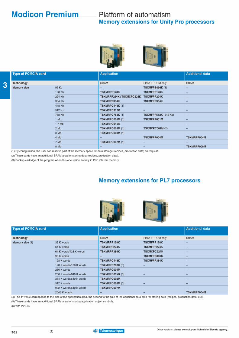
Other versions: please consult your Schneider Electric agency.3/22
3
Platform of automatismMemory extensions for Unity Pro processors
Type of PCMCIA card Application Additional data
Technology SRAM Flash EPROM only SRAM
Memory size 96 Kb – TSXMFPB096K (3) –
128 Kb TSXMRPP128K TSXMFPP128K –
224 Kb TSXMRPP224K / TSXMCPC224K TSXMFPP224K –
384 Kb TSXMRPP384K TSXMFPP384K –
448 Kb TSXMRPC448K (1) – –
512 kb TSXMCPC512K – –
768 Kb TSXMRPC768K (1) TSXMFPP512K (512 Ko) –
1 Mb TSXMRPC001M (1) TSXMFPP001M –
1.7 Mb TSXMRPC01M7 – –
2 Mb TSXMRPC002M (1) TSXMCPC002M (2) –
3 Mb TSXMRPC003M (1) – –
4 Mb – TSXMFPP004M TSXMRPF004M
7 Mb TSXMRPC007M (1) – –
8 Mb – – TSXMRPF008M
(1) By configuration, the user can reserve part of the memory space for data storage (recipes, production data) on request.
(2) These cards have an additional SRAM area for storing data (recipes, production data).
(3) Backup cartridge of the program when this one reside entirely in PLC internal memory.
Memory extensions for PL7 processors
Type of PCMCIA card Application Additional data
Technology SRAM Flash EPROM only SRAM
Memory size (4) 32 K words TSXMRPP128K TSXMFPP128K –
64 K words TSXMRPP224K TSXMFPP224K –
64 K words/128 K words TSXMRPP384K TSXMCPC224K –
96 K words – TSXMFPB096K –
128 K words TSXMRPC448K TSXMFPP384K –
128 K words/128 K words TSXMRPC768K (5) – –
256 K words TSXMRPC001M – –
256 K words/640 K words TSXMRPC01M7 (5) – –
384 K words/640 K words TSXMRPC002M – –
512 K words TSXMRPC003M (5) – –
992 K words/640 K words TSXMRPC007M – –
2048 K words – – TSXMRPF004M
(4) The 1st value corresponds to the size of the application area, the second to the size of the additional data area for storing data (recipes, production data, etc).
(5) These cards have an additional SRAM area for storing application object symbols.
(6) with PV0.05
Modicon Premium
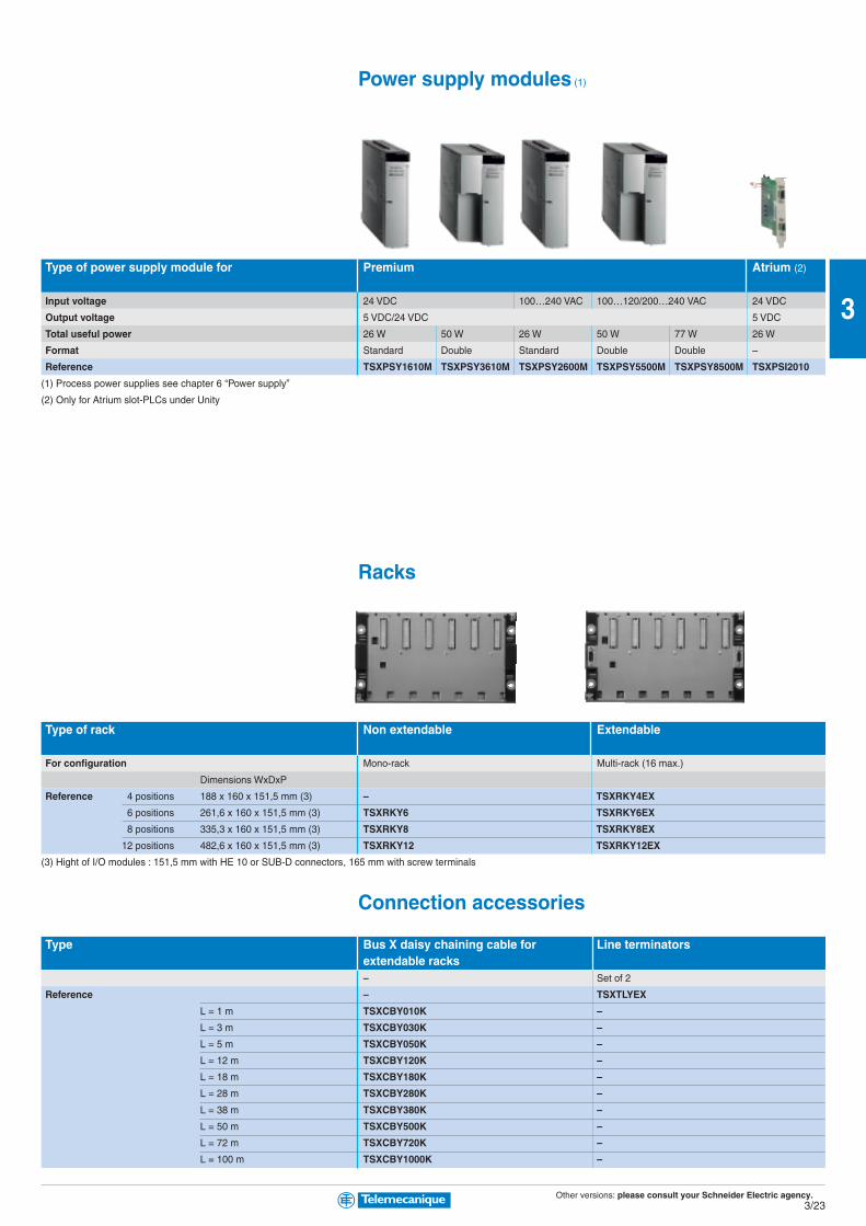
Other versions: please consult your Schneider Electric agency.3/23
3
Power supply modules (1)
Type of power supply module for Premium Atrium (2)
Input voltage 24 VDC 100…240 VAC 100…120/200…240 VAC 24 VDC
Output voltage 5 VDC/24 VDC 5 VDC
Total useful power 26 W 50 W 26 W 50 W 77 W 26 W
Format Standard Double Standard Double Double –
Reference TSXPSY1610M TSXPSY3610M TSXPSY2600M TSXPSY5500M TSXPSY8500M TSXPSI2010
(1) Process power supplies see chapter 6 “Power supply”
(2) Only for Atrium slot-PLCs under Unity
Racks
Type of rack Non extendable Extendable
For configuration Mono-rack Multi-rack (16 max.)
Dimensions WxDxP
Reference 4 positions 188 x 160 x 151,5 mm (3) – TSXRKY4EX
6 positions 261,6 x 160 x 151,5 mm (3) TSXRKY6 TSXRKY6EX
8 positions 335,3 x 160 x 151,5 mm (3) TSXRKY8 TSXRKY8EX
12 positions 482,6 x 160 x 151,5 mm (3) TSXRKY12 TSXRKY12EX
(3) Hight of I/O modules : 151,5 mm with HE 10 or SUB-D connectors, 165 mm with screw terminals
Connection accessories
Type Bus X daisy chaining cable for Line terminatorsextendable racks– Set of 2
Reference – TSXTLYEX
L = 1 m TSXCBY010K –
L = 3 m TSXCBY030K –
L = 5 m TSXCBY050K –
L = 12 m TSXCBY120K –
L = 18 m TSXCBY180K –
L = 28 m TSXCBY280K –
L = 38 m TSXCBY380K –
L = 50 m TSXCBY500K –
L = 72 m TSXCBY720K –
L = 100 m TSXCBY1000K –
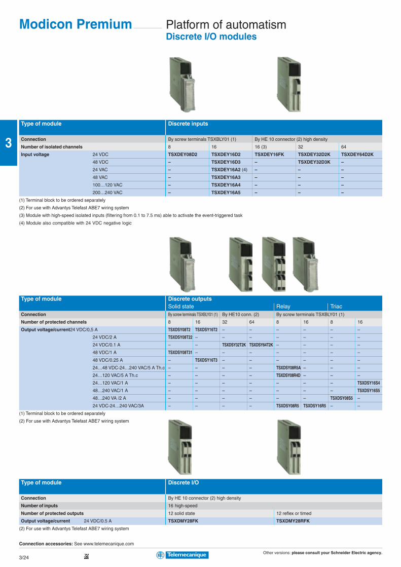
Other versions: please consult your Schneider Electric agency.3/24
3
Platform of automatismDiscrete I/O modules
Type of module Discrete inputs
Connection By screw terminals TSXBLY01 (1) By HE 10 connector (2) high density
Number of isolated channels 8 16 16 (3) 32 64
Input voltage 24 VDC TSXDEY08D2 TSXDEY16D2 TSXDEY16FK TSXDEY32D2K TSXDEY64D2K
48 VDC – TSXDEY16D3 – TSXDEY32D3K –
24 VAC – TSXDEY16A2 (4) – – –
48 VAC – TSXDEY16A3 – – –
100…120 VAC – TSXDEY16A4 – – –
200…240 VAC – TSXDEY16A5 – – –
(1) Terminal block to be ordered separately
(2) For use with Advantys Telefast ABE7 wiring system
(3) Module with high-speed isolated inputs (filtering from 0.1 to 7.5 ms) able to activate the event-triggered task
(4) Module also compatible with 24 VDC negative logic
Type of module Discrete outputsSolid state Relay Triac
Connection By screw terminals TSXBLY01 (1) By HE10 conn. (2) By screw terminals TSXBLY01 (1)
Number of protected channels 8 16 32 64 8 16 8 16
Output voltage/current24 VDC/0,5 A TSXDSY08T2 TSXDSY16T2 – – – – – –
24 VDC/2 A TSXDSY08T22 – – – – – – –
24 VDC/0.1 A – – TSXDSY32T2K TSXDSY64T2K – – – –
48 VDC/1 A TSXDSY08T31 – – – – – – –
48 VDC/0.25 A – TSXDSY16T3 – – – – – –
24…48 VDC-24…240 VAC/5 A Th.c – – – – TSXDSY08R5A – – –
24…120 VAC/5 A Th.c – – – – TSXDSY08R4D – – –
24…120 VAC/1 A – – – – – – – TSXDSY16S4
48…240 VAC/1 A – – – – – – – TSXDSY16S5
48…240 VA /2 A – – – – – – TSXDSY08S5 –
24 VDC-24…240 VAC/3A – – – – TSXDSY08R5 TSXDSY16R5 – –
(1) Terminal block to be ordered separately
(2) For use with Advantys Telefast ABE7 wiring system
Type of module Discrete I/O
Connection By HE 10 connector (2) high density
Number of inputs 16 high-speed
Number of protected outputs 12 solid state 12 reflex or timed
Output voltage/current 24 VDC/0.5 A TSXDMY28FK TSXDMY28RFK
(2) For use with Advantys Telefast ABE7 wiring system
Connection accessories: See www.telemecanique.com
Modicon Premium
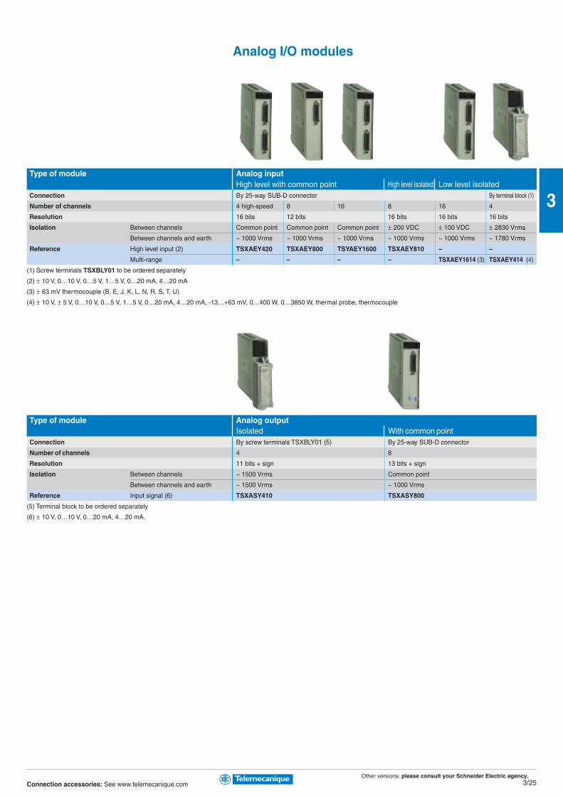
Other versions: please consult your Schneider Electric agency.3/25
3
Analog I/O modules
Type of module Analog inputHigh level with common point High level isolated Low level isolated
Connection By 25-way SUB-D connector By terminal block (1)
Number of channels 4 high-speed 8 16 8 16 4
Resolution 16 bits 12 bits 16 bits 16 bits 16 bits
Isolation Between channels Common point Common point Common point ± 200 VDC ± 100 VDC ± 2830 Vrms
Between channels and earth ~ 1000 Vrms ~ 1000 Vrms ~ 1000 Vrms ~ 1000 Vrms ~ 1000 Vrms ~ 1780 Vrms
Reference High level input (2) TSXAEY420 TSXAEY800 TSYAEY1600 TSXAEY810 – –
Multi-range – – – – TSXAEY1614 (3) TSXAEY414 (4)
(1) Screw terminals TSXBLY01 to be ordered separately
(2) ± 10 V, 0…10 V, 0…5 V, 1…5 V, 0…20 mA, 4…20 mA
(3) ± 63 mV thermocouple (B, E, J, K, L, N, R, S, T, U)
(4) ± 10 V, ± 5 V, 0…10 V, 0…5 V, 1…5 V, 0…20 mA, 4…20 mA, -13…+63 mV, 0…400 W, 0…3850 W, thermal probe, thermocouple
Type of module Analog outputIsolated With common point
Connection By screw terminals TSXBLY01 (5) By 25-way SUB-D connector
Number of channels 4 8
Resolution 11 bits + sign 13 bits + sign
Isolation Between channels ~ 1500 Vrms Common point
Between channels and earth ~ 1500 Vrms ~ 1000 Vrms
Reference Input signal (6) TSXASY410 TSXASY800
(5) Terminal block to be ordered separately
(6) ± 10 V, 0…10 V, 0…20 mA, 4…20 mA.
Connection accessories: See www.telemecanique.com
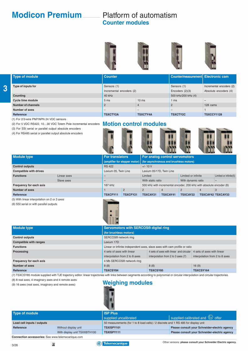
Other versions: please consult your Schneider Electric agency.3/26
3
Platform of automatismCounter modules
Type of module Counter Counter/measurement Electronic cam
Type of inputs for Sensors (1) Sensors (1) Incremental encoders (2)
Incremental encoders (2) Encoders (2)(3) Absolute encoders (4)
Counting 40 kHz 500 kHz/200 kHz (4)
Cycle time module 5 ms 10 ms 1 ms –
Number of channels 2 4 2 128 cams
Number of axes – – – 1
Reference TSXCTY2A TSXCTY4A TSXCTY2C TSXCCY1128
(1) For 2/3-wire PNP/NPN 24 VDC sensors
(2) For 5 VDC RS422, 10…30 VDC Totem Pole incremental encoders
(3) For SSI serial or parallel output absolute encoders
(4) For RS485 serial or parallel output absolute encoders
Module type For translators For analog control servomotors(amplifier for stepper motor) (for asynchronous and brushless motors)
Control outputs RS 422 +/- 10 V
Compatible with drives Lexium 05, Twin Line Lexium 05/17D, Twin Line
Functions Linear axes – Limited Limited or infinite Limited or infinite(5)
Slave axes – With static ratio With dynamic ratio –
Frequency for each axis 187 kHz 500 kHz with incremental encoder, 200 kHz with absolute encoder (6)
Number of axes 1 2 2 4 2 4 3
Reference TSXCFY11 TSXCFY21 TSXCAY21 TSXCAY41 TSXCAY22 TSXCAY42 TSXCAY33
(5) With linear interpolation on 2 or 3 axes
(6) SSI serial or with parallel outputs
Module type Servomotors with SERCOS® digital ring(for brushless motors)
Control outputs SERCOS® network ring
Compatible with ranges Lexium 17D
Functions Linear or infinite independent axes, slave axes with cam profile or ratio
Processing 4 sets of axes with linear 4 sets of axes with linear and circular 4 sets of axes with linear
interpolation from 2 to 8 axes interpolation from 2 to 3 axes (7) interpolation from 2 to 8 axes
Frequency for each axis 4 Mb SERCOS® network ring
Number of axes 8 (8) 8 (8) 16 (9)
Reference TSXCSY84 TSXCSY85 TSXCSY164
(7) TSXCSY85 module supplied with TJE trajectory editor: linear trajectories with links between segments according to polynomial or circular interpolation and circular trajectories.
(8) 8 real axes, 4 imaginary axes and 4 remote axes
(9) 16 axes (real axes, imaginary and remote axes)
Type of module ISP Plussupplied uncalibrated supplied calibrated and offer
Load cell inputs / outputs 50 measurements (for 1 to 8 load cells) / 2 discrete and 1 RS 485 for display unit
Reference Without display unit TSXISPY101 Please consult your Schneider-electric agency
With display unit TSXXBTH100 TSXISPY111 Please consult your Schneider-electric agency
Connection accessories: See www.telemecanique.com
Modicon Premium
Weighing modules
Motion control modules

Other versions: please consult your Schneider Electric agency.3/27
3
Communication modules
Type of module Ethernet TCP/IP
Speed 10 Mbps 10/100 Mbps
Standard services Ethway, TCP/IP (Uni-TE, Modbus) TCP/IP (Uni-TE, Modbus)
Transparent Ready Classe C10 B30 B30 C30 D10
Global Data – Yes Yes Yes –
I/O Scanning – Yes Yes Yes –
TCP Open Yes – – Yes –
Web server Standard services Yes Yes Yes Yes Yes
FactoryCast services Yes – – Yes –
FactoryCast HMI services – – – – Yes
Reference TSXETY110WS TSXP57 (1) TSXETY4103 TSXETY5103 TSXWMY100
(1) References: see pages 3/18 and 3/19, Premium processors with integrated Ethernet TCP/IP port
Type of module AS-Interface CANopen Fipio manager INTERBUS Profibus DPcabling system machine bus fieldbus fieldbus fieldbus
Name and description In-rack PCMCIA Integrated port In-rack In-rack
Speed 167 Kbps 20 K…1 Mbps 1 Mbps 0.5 Mbps 9.6 K…12 Mbps
Reference TSXSAY1000 TSXCPP110 TSXP57 (2) TSXIBY100 TSXPBY100
(2) References: see pages 3/18 and 3/19, Premium processors with integrated Fipio port
Type of module Serial linksUni-Telway Modbus ASCII
Name and description Integrated port In-rack PCMCIA In-rack PCMCIA PCMCIA
Speed 19.2 Kbps 19.2 Kbps 1.2...19.2 Kbps 19.2 Kbps 1.2...19.2 Kbps 1.2...19.2 Kbps
Reference With interface RS 485 TSXP57 (1) TSXSCY21601 (2) TSXSCP114 TSXSCY11601 TSXSCP114 TSXSCP114
RS 232D – – TSXSCP111 – TSXSCP111 TSXSCP111
20mA CL – – TSXSCP112 – TSXSCP112 TSXSCP112
(1) References: see pages 3/18 and 3/19, Premium processors with integrated Ethernet TCP/IP port
(2) Also designed for Modbus serial (channel 0).
Type of module Other networksModbus Plus Fipway Fipio (agent function)
Name and description PCMCIA card PCMCIA card PCMCIA card
Speed 1 Mbps 1 Mbps 1 Mbps
Reference TSXMBP100 TSXFPP20 TSXFPP10
Connection accessories: See www.telemecanique.com
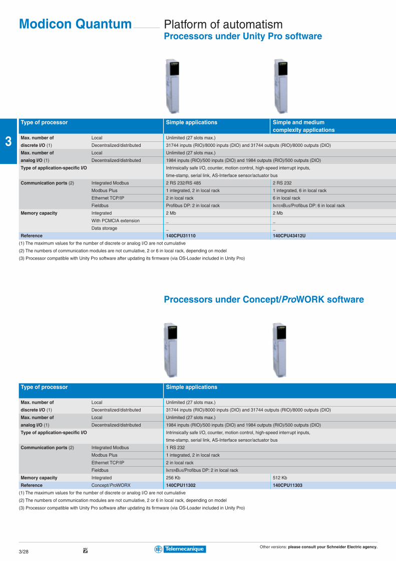
Other versions: please consult your Schneider Electric agency.3/28
3
Platform of automatismProcessors under Unity Pro software
Type of processor Simple applications Simple and mediumcomplexity applications
Max. number of Local Unlimited (27 slots max.)
discrete I/O (1) Decentralized/distributed 31744 inputs (RIO)/8000 inputs (DIO) and 31744 outputs (RIO)/8000 outputs (DIO)
Max. number of Local Unlimited (27 slots max.)
analog I/O (1) Decentralized/distributed 1984 inputs (RIO)/500 inputs (DIO) and 1984 outputs (RIO)/500 outputs (DIO)
Type of application-specific I/O Intrinsically safe I/O, counter, motion control, high-speed interrupt inputs,
time-stamp, serial link, AS-Interface sensor/actuator bus
Communication ports (2) Integrated Modbus 2 RS 232/RS 485 2 RS 232
Modbus Plus 1 integrated, 2 in local rack 1 integrated, 6 in local rack
Ethernet TCP/IP 2 in local rack 6 in local rack
Fieldbus Profibus DP: 2 in local rack INTERBUS/Profibus DP: 6 in local rack
Memory capacity Integrated 2 Mb 2 Mb
With PCMCIA extension _ _
Data storage _ _
Reference 140CPU31110 140CPU43412U
(1) The maximum values for the number of discrete or analog I/O are not cumulative
(2) The numbers of communication modules are not cumulative, 2 or 6 in local rack, depending on model
(3) Processor compatible with Unity Pro software after updating its firmware (via OS-Loader included in Unity Pro)
Processors under Concept/ProWORK software
Type of processor Simple applications
Max. number of Local Unlimited (27 slots max.)
discrete I/O (1) Decentralized/distributed 31744 inputs (RIO)/8000 inputs (DIO) and 31744 outputs (RIO)/8000 outputs (DIO)
Max. number of Local Unlimited (27 slots max.)
analog I/O (1) Decentralized/distributed 1984 inputs (RIO)/500 inputs (DIO) and 1984 outputs (RIO)/500 outputs (DIO)
Type of application-specific I/O Intrinsically safe I/O, counter, motion control, high-speed interrupt inputs,
time-stamp, serial link, AS-Interface sensor/actuator bus
Communication ports (2) Integrated Modbus 1 RS 232
Modbus Plus 1 integrated, 2 in local rack
Ethernet TCP/IP 2 in local rack
Fieldbus INTERBUS/Profibus DP: 2 in local rack
Memory capacity Integrated 256 Kb 512 Kb
Reference Concept/ProWORX 140CPU11302 140CPU11303
(1) The maximum values for the number of discrete or analog I/O are not cumulative
(2) The numbers of communication modules are not cumulative, 2 or 6 in local rack, depending on model
(3) Processor compatible with Unity Pro software after updating its firmware (via OS-Loader included in Unity Pro)
Modicon Quantum
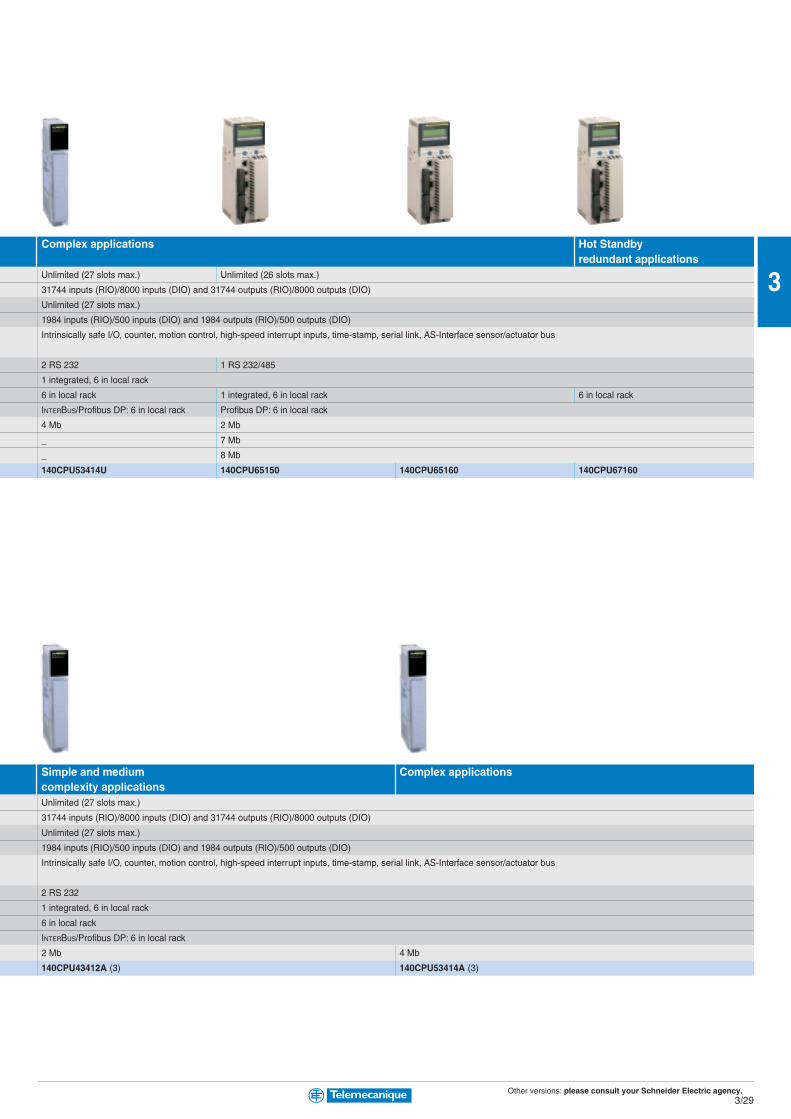
Other versions: please consult your Schneider Electric agency.3/29
3
Complex applications Hot Standbyredundant applications
Unlimited (27 slots max.) Unlimited (26 slots max.)
31744 inputs (RIO)/8000 inputs (DIO) and 31744 outputs (RIO)/8000 outputs (DIO)
Unlimited (27 slots max.)
1984 inputs (RIO)/500 inputs (DIO) and 1984 outputs (RIO)/500 outputs (DIO)
Intrinsically safe I/O, counter, motion control, high-speed interrupt inputs, time-stamp, serial link, AS-Interface sensor/actuator bus
2 RS 232 1 RS 232/485
1 integrated, 6 in local rack
6 in local rack 1 integrated, 6 in local rack 6 in local rack
INTERBUS/Profibus DP: 6 in local rack Profibus DP: 6 in local rack
4 Mb 2 Mb
_ 7 Mb
_ 8 Mb
140CPU53414U 140CPU65150 140CPU65160 140CPU67160
Simple and medium Complex applicationscomplexity applicationsUnlimited (27 slots max.)
31744 inputs (RIO)/8000 inputs (DIO) and 31744 outputs (RIO)/8000 outputs (DIO)
Unlimited (27 slots max.)
1984 inputs (RIO)/500 inputs (DIO) and 1984 outputs (RIO)/500 outputs (DIO)
Intrinsically safe I/O, counter, motion control, high-speed interrupt inputs, time-stamp, serial link, AS-Interface sensor/actuator bus
2 RS 232
1 integrated, 6 in local rack
6 in local rack
INTERBUS/Profibus DP: 6 in local rack
2 Mb 4 Mb
140CPU43412A (3) 140CPU53414A (3)

Other versions: please consult your Schneider Electric agency.3/30
3
Platform of automatismPower supply modules (1)
ype of power supply module for Quantum
Input voltage 24 VDC 48…60 VDC 100…150 VDC 120…230 VAC 115/230 VAC
Output current 8 A/3 A (4) 8 A 8 A/3 A 8 A/3 A (1) 11 A
Reference Type Standalone (2) 140CPS21100 – 140CPS51100 140CPS11100 –
Summable 140CPS21400 140CPS41400 – – 140CPS11420
Redundant 140CPS22400 140CPS42400 140CPS52400 140CPS12400 140CPS12420
(1) Process power supplies see chapter 6 “Power supply”
(2) The output current for the standalone power supply modules is 3 A
PCMCIA memory extensions
Type of PCMCIA card Application Additional datafor Unity processors 140CPU65/67Technology SRAM Flash EPROM SRAM
Memory size 512 Kb/512 Kb (3) – TSXMCPC512K –
1 Mb (4) TSXMRPC001M TSXMFPP001M –
2 Mb (4) TSXMRPC002M TSXMFPP002M –
2 Mb/1 Mb (3) – TSXMCPC002M –
3 Mb (4) TSXMRPC003M – –
4 Mb – TSXMFPP004M TSXMRPF004M
7 Mb (4) TSXMRPC007M – –
8 Mb – – TSXMRPF008M
(3) The 1st value corresponds to the size of the application area, the second to the size of the additional data area for storing data (recipes, production data, etc)
(4) By configuration the user can reserve part of the memory space for data storage (recipes, production data, etc)
Modicon Quantum

Other versions: please consult your Schneider Electric agency.3/31
3
Type Racks Rack extension module (1)
Dimensions WxDxH
References 2 slots 104x104x290 mm 140XBP00200 –
3 slots 143x104x290 mm 140XBP00300 –
4 slots 184x104x290 mm 140XBP00400 –
6 slots 265x104x290 mm 140XBP00600 –
10 slots 428x104x290 mm 140XBP01000 –
16 slots 671x104x290 mm 140XBP01600 –
Rack extension – 140XBE10000
(1) Local extension module, to be placed in main rack and secondary rack.
Connection accessories (2)
Type Cable for extension racks (main and secondary)
References L = 1 m 140XCA71703
L = 2 m 140XCA71706
L = 3 m 140XCA71709
(2) Other accessories: See www.telemecanique.com
Racks

Other versions: please consult your Schneider Electric agency.3/32
3
Platform of automatismDiscrete I/O modules
Type of module Discrete inputs
Connection By screw terminals 140XTS00200 (to be ordered separately)
Number of isolated channels 16 4 groups of 8 3 groups of 8 2 groups of 8 6 groups of 16 8 groups of 2
Input voltage 5 VDC TTL (negative logic) – 140DDI15310 – – – –
24 VDC – 140DDI35300(1) – – 140DDI36400 –
10…60 VDC – 140DDI85300 – – – 140DDI84100
20…30 VDC – 140DSI35300(1) – – – –
125 VDC – – 140DDI67300 – – –
24 VAC 140DAI34000 140DAI35300 – – – –
48 VAC 140DAI44000 140DAI45300 – – – –
115 VAC 140DAI54000 140DAI55300 – 140DAI54300 – –
230 VAC 140DAI74000 140DAI75300 – – – –
(1) For negative logic, replace 00 at the end of the reference with 10, for example 140DDI35300 becomes 140DDI35310.
Type of module Discrete outputsSolid state
Connection By screw terminals 140XTS00200 (to be ordered separately)
Number of protected channels 16 4 groups of 8 4 groups of 4 2 groups of 8 6 groups of 16 2 groups of 6
Output voltage/current 5 VDC TTL/0.075 A (2) – 140DDO15310 – – – –
24 VDC/0.5 A – 140DDO35301(1) – – – –
10…30 VDC/0.5 A (3) – 140DVO85300 – – – –
19.2…30 VDC/0.5 A – – – – 140DDO36400 –
10…60 VDC/2 A – – – 140DDO84300 – –
24...125 VDC/0.75 A – – – – – 140DDO88500
24…48 VAC/4 A – – 140DAO84220 – – –
24…115 VAC/4 A 140DAO84010 – – – – –
24…230 VAC/ 4-3 A 140DAO84000 140DAO85300 – – – –
100...230 VAC/4-3 A – – 140DAO84210 – – –
(1) For negative logic, replace 01 at the end of the reference with 10, for example 140DDO35301 becomes 140DDO35310.
(2) Negative logic
(3) Controlled outputs
Type of module Discrete I/O Discrete outputsSolid state Relay
Connection By screw terminals 140XTS00200 (to be ordered separately) –
Number of I/O 2 groups of 8/2 groups of 4 1 group of 4/ –/16 NO –/8 NO/NC
4 isolated
Input voltage 24 VDC 125 VAC 125 VDC – –
Output voltage/current 30 VDC/15 A 125 VAC/4 A 125 VDC/4 A 150 VDC or 250 VAC/2 A 150 VDC or 250 VAC/5 A
Reference 140DDM39000 140DAM59000 140DDM69000 140DRA84000 140DRC83000
Connection accessories: See www.telemecanique.com
Modicon Quantum

Other versions: please consult your Schneider Electric agency.3/33
3
Analog I/O modules
Type of module Analog inputs
Connection By screw terminals 140XTS00200 (to be ordered separately)
Number of channels 8 16 8
Input signal 4…20 mA 0…25/20 mA (1) Thermal probe Thermocouple
1…5 V 4…20 mA Pt, Ni (2)
Resolution 12 bits 0…25000 points 16 bits 12 bits + sign 16 bits
Reference 140ACI03000 140ACI04000 140AVI03000 140ARI03010 140ATI03000
(1) 0…25 mA, ± 20 mA, 4…20 mA, 0…10 V, ± 10 V, 0…5 V, ± 5 V, 1…5 V.
(2) Type B, E, J, K, R, S, T, mV
Type of module Analog output
Connection By screw terminals 140XTS00200 (to be ordered separately)
Number of channels 4 8 4
Input signal 4…20 mA 0…25/20 mA 0…10 V, ± 10 V
4…20 mA 0…5 V, ± 5 V
Resolution 12 bits 0…25000 points 12 bits
Reference 140ACO02000 140ACO13000 140AVO02000
Type of module Analog I/O
Connection By screw terminals 140XTS00200 (to be ordered separately)
Number of inputs 4
Number of outputs 2
Input signal 0…20 mA, ± 20 mA, 4…20 mA, 0…10 V, ± 10 V, 0…5 V, ± 5 V, 1…5 V.
Resolution Inputs 16 bits, outputs 12 bits
Reference 140AMM09000
Connection accessories: See www.telemecanique.com
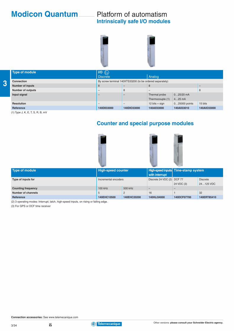
Other versions: please consult your Schneider Electric agency.3/34
3
Platform of automatismIntrinsically safe I/O modules
Type of module I/ODiscrete Analog
Connection By screw terminal 140XTS33200 (to be ordered separately)
Number of inputs 8 – 8 –
Number of outputs – 8 – 8
Input signal – – Thermal probe 0…25/20 mA
Thermocouple (1) 4…25 mA
Resolution – – 12 bits + sign 0…25000 points 15 bits
Reference 140DII33000 140DIO33000 140AII33000 140AII33010 140AIO33000
(1) Type J, K, E, T, S, R, B, mV
Counter and special purpose modules
Type of module High-speed counter High-speed inputs Time-stamp systemwith interrupt
Type of inputs for Incremental encoders Discrete 24 VDC (2) DCF 77 Discrete
24 VDC (3) 24…125 VDC
Counting frequency 100 kHz 500 kHz – –
Number of channels 5 2 16 1 32
Reference 140EHC10500 140EHC20200 140HLI34000 140DCF07700 140ERT85410
(2) 3 operating modes: Interrupt, latch, high-speed inputs, on rising or falling edge.
(3) For GPS or DCF time receiver
Connection accessories: See www.telemecanique.com
Modicon Quantum
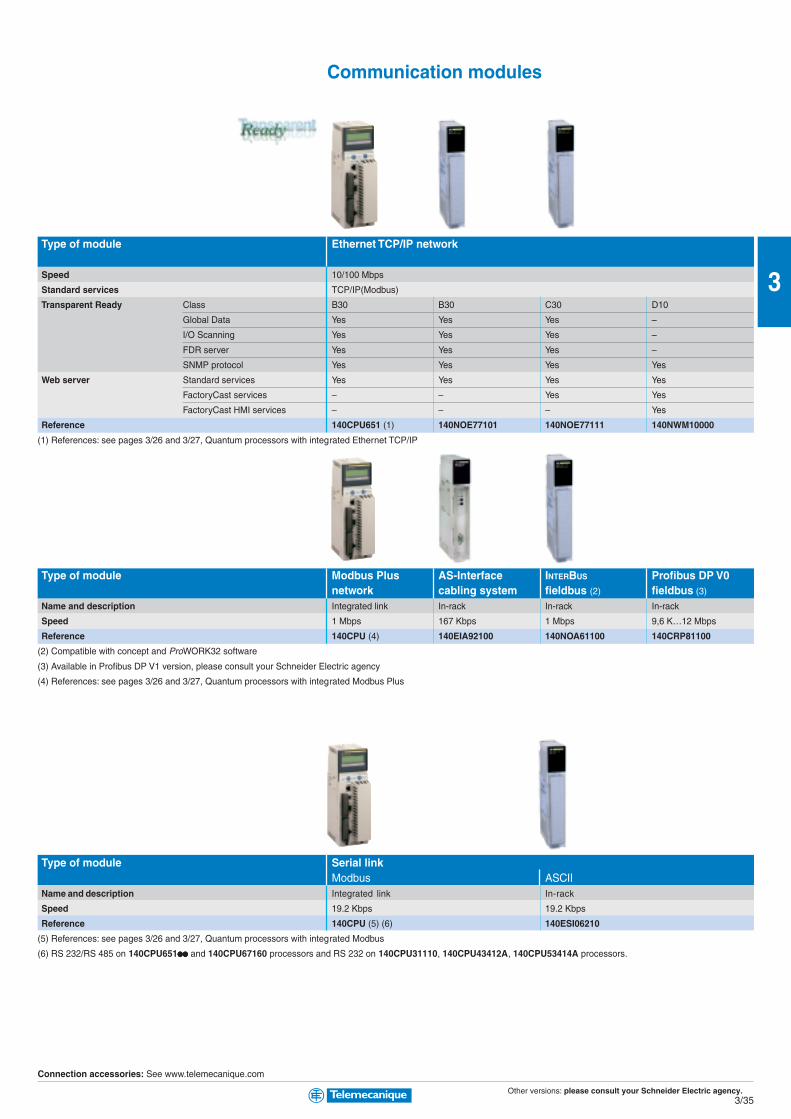
Other versions: please consult your Schneider Electric agency.3/35
3
Communication modules
Type of module Ethernet TCP/IP network
Speed 10/100 Mbps
Standard services TCP/IP(Modbus)
Transparent Ready Class B30 B30 C30 D10
Global Data Yes Yes Yes –
I/O Scanning Yes Yes Yes –
FDR server Yes Yes Yes –
SNMP protocol Yes Yes Yes Yes
Web server Standard services Yes Yes Yes Yes
FactoryCast services – – Yes Yes
FactoryCast HMI services – – – Yes
Reference 140CPU651 (1) 140NOE77101 140NOE77111 140NWM10000
(1) References: see pages 3/26 and 3/27, Quantum processors with integrated Ethernet TCP/IP
Type of module Modbus Plus AS-Interface INTERBUS Profibus DP V0network cabling system fieldbus (2) fieldbus (3)
Name and description Integrated link In-rack In-rack In-rack
Speed 1 Mbps 167 Kbps 1 Mbps 9,6 K…12 Mbps
Reference 140CPU (4) 140EIA92100 140NOA61100 140CRP81100
(2) Compatible with concept and ProWORK32 software
(3) Available in Profibus DP V1 version, please consult your Schneider Electric agency
(4) References: see pages 3/26 and 3/27, Quantum processors with integrated Modbus Plus
Type of module Serial linkModbus ASCII
Name and description Integrated link In-rack
Speed 19.2 Kbps 19.2 Kbps
Reference 140CPU (5) (6) 140ESI06210
(5) References: see pages 3/26 and 3/27, Quantum processors with integrated Modbus
(6) RS 232/RS 485 on 140CPU651pppppppppp and 140CPU67160 processors and RS 232 on 140CPU31110, 140CPU43412A, 140CPU53414A processors.
Connection accessories: See www.telemecanique.com
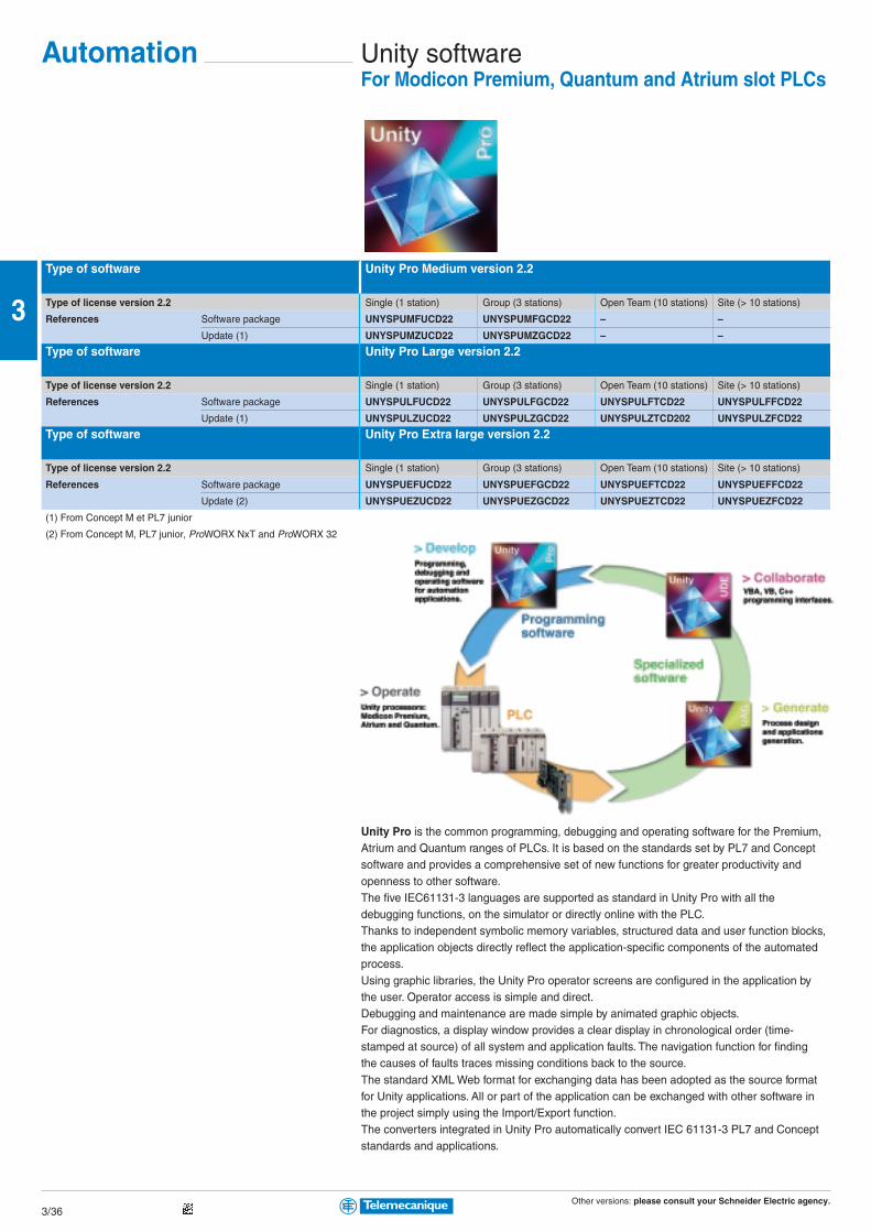
Other versions: please consult your Schneider Electric agency.3/36
3
Unity softwareFor Modicon Premium, Quantum and Atrium slot PLCs
Automation
Type of software Unity Pro Medium version 2.2
Type of license version 2.2 Single (1 station) Group (3 stations) Open Team (10 stations) Site (> 10 stations)
References Software package UNYSPUMFUCD22 UNYSPUMFGCD22 – –
Update (1) UNYSPUMZUCD22 UNYSPUMZGCD22 – –
Type of software Unity Pro Large version 2.2
Type of license version 2.2 Single (1 station) Group (3 stations) Open Team (10 stations) Site (> 10 stations)
References Software package UNYSPULFUCD22 UNYSPULFGCD22 UNYSPULFTCD22 UNYSPULFFCD22
Update (1) UNYSPULZUCD22 UNYSPULZGCD22 UNYSPULZTCD202 UNYSPULZFCD22
Type of software Unity Pro Extra large version 2.2
Type of license version 2.2 Single (1 station) Group (3 stations) Open Team (10 stations) Site (> 10 stations)
References Software package UNYSPUEFUCD22 UNYSPUEFGCD22 UNYSPUEFTCD22 UNYSPUEFFCD22
Update (2) UNYSPUEZUCD22 UNYSPUEZGCD22 UNYSPUEZTCD22 UNYSPUEZFCD22
(1) From Concept M et PL7 junior
(2) From Concept M, PL7 junior, ProWORX NxT and ProWORX 32
Unity Pro is the common programming, debugging and operating software for the Premium,Atrium and Quantum ranges of PLCs. It is based on the standards set by PL7 and Conceptsoftware and provides a comprehensive set of new functions for greater productivity andopenness to other software.The five IEC61131-3 languages are supported as standard in Unity Pro with all thedebugging functions, on the simulator or directly online with the PLC.Thanks to independent symbolic memory variables, structured data and user function blocks,the application objects directly reflect the application-specific components of the automatedprocess.Using graphic libraries, the Unity Pro operator screens are configured in the application bythe user. Operator access is simple and direct.Debugging and maintenance are made simple by animated graphic objects.For diagnostics, a display window provides a clear display in chronological order (time-stamped at source) of all system and application faults. The navigation function for findingthe causes of faults traces missing conditions back to the source.The standard XML Web format for exchanging data has been adopted as the source formatfor Unity applications. All or part of the application can be exchanged with other software inthe project simply using the Import/Export function.The converters integrated in Unity Pro automatically convert IEC 61131-3 PL7 and Conceptstandards and applications.

Other versions: please consult your Schneider Electric agency.3/37
3
Unity softwareSpecialist tools
Software dedicated for integrators systems
Type of software Unity Pro XL AllianceType of license version 2.2 Single (1 station) Group (10 stations)
References Software package UNYSPUEFUAL22 UNYSPUEFTAL22
Legacy upgrade UNYSPUEZUAL22 UNYSPUEZTAL22
Unity upgrade UNYSPUQZUAL22 UNYSPUQZTAL22
Type of software PLC Suite Alliance V2.2Type of license version 2.2 Single (1 station) Group (10 stations)
References Software bundle UNYSPUQFUAL22 UNYSPUQFTAL22
(1) For Concept, PL7 Junior, ProWORX.
SFC View application diagnostic and monitoring software
Type of software Unity SFC ViewType of license version 2.0 Single (1 station) Group (10 stations) Site (100 stations)
References Software package UNYSDUMFUCD20 UNYSDUMFTCD20 UNYSDUMFFCD20
EF/EFB function development software in C language
Type of software Unity EFB ToolkitType of license Single (1 station), english version (software and manual)
References Software package UNYSPUZFUCD20E
Renewal UNYCSPSPUZBU
Software for designing and generating batch/process applications
Type of software Unity UAG (Unity application generator)Type of license version 2.2 Single (1 station) Site
References Medium Software package UAGSEWMFUCD22 UAGSEWMFFCD22
Large Software package UAGSEWLFUCD22 UAGSEWLFFCD22
Pack for developing specific solutions
Type of software Unity UDE (Unity Developer’s Edition)
Type of license Single (1 station)
References Software package UNYUDEVFUCD20E
Other versions: please consult your Schneider Electric agency.3/38
3
Programming softwareFor Modicon TSX Micro, Premium and Atrium slot-PLCs
PL7 is the common programming, debugging and operating software for the TSX Micro and Premium
ranges of PLCs as well as Atrium coprocessors (see pages 3/12, 3/18 and 3/26).
PL7 offers 4 IEC languages: Instruction List (IL), Ladder Diagram (LD), Structured Text (ST) and
Sequential Function Chart (SFC). You can use the most suitable language for each function in your
application, making use of the multi-tasking structure of the processors.
For using application-specific functions, PL7 directly integrates the application-specific screens
required for configuration and adjustment as well as supervisory and diagnostics activities.
Type of software PL7 Micro for TSX Micro platform
Type of license version 4.5 Single (1 station) Single with SyCon V2.8 Group (3 stations) Open Team (10 stations)
Reference Software package (1) TLXCDPL7MPPU45M TLXCDPL7MPPC45M TLXCD3PL7MPPU45M TLXOTPL7MP45M
Update (2) TLXRCDPL7MP45M TLXRCDPL7MPC45M TLXRCD3PL7MP45M –
PL7 Junior for TSX Micro/Premium and Atrium coprocessor platformsType of license version 4.5 Single (1 station) Group (3 stations)
Reference Software package (1) TLXCDPL7JPU45M TLXCD3PL7JPU45M
Update (2) TLXRCDPL7JP45M TLXRC3DPL7JP45M
Upgrade (3) TLXUCDPL7JP45M TLXUCD3PL7JP45M
PL7 Pro for TSX Micro/Premium and Atrium coprocessor platformsType of license version 4.5 Single (1 station) Group (3 stations) Open Team (10 stations) Open Site
Reference Software package (1) TLXCDPL7PPU45M TLXCD3PL7PPU45M TLXOTPL7PP45M TLXOSPL7PP45M
Update (2) TLXRCDPL7PP45M TLXRCD3PL7PP45M – –
Upgrade (3) TLXUCDPL7PP45M TLXUCD3PL7PP45M – –
(1) PU at the end of the reference: software package supplied with cable for USB port on PC, replace with P for cable for RS 232C port on PC.
(2) From the previous software version. (3) From lower level, earlier version software.
Specialist toolsEF function development software in C language
Type of software PL7 SDKC for EF function development software in C languagePL7 SDKC software extension For PL7 Micro/Junior/Pro
Reference TLXLSDKCPL741M
Development of applications in C language
Type of software PL7 FUZ for processing process applications using fuzzy logicPL7 FUZ software extension For PL7 Micro/Junior/Pro, TSX Micro/Premium
Reference TLXLPL7FUZ34M
Comparison of PL7 applications
Type of software PL7 DIF for comparison of applicationsPL7 DIF software extension For PL7 Pro, TSX Micro/Premium
Type of license Single (1 station) Site (> 10 stations)
Reference TLXCDPL7DIF42 TLXOSPL7DIF42
Availability of control systems based on Premium platforms
Type of software Warm Standby redundantWarm Standby software extension For PL7 Junior/Pro
Type of license Single (1 station)
Reference TLXCDWSBYP40F / E
Automation

Other versions: please consult your Schneider Electric agency.3/39
3
Programming softwareFor Modicon Quantum, Momentum
Concept is the IEC programming software for the Momentum and Quantum range of PLCs. It provides
advanced Microsoft Windows based tools that deliver a multi-language development environment for
control system programming.
Uses familiar, standardized editors, bundled in a single application to create and integrate PLC control,
communication and diagnostic logic.
Five IEC editors give users the freedom to choose the programming language that fits their application
requirements: Function Block Diagram (FBD), Ladder Diagram (LD), Sequential Function Chart (SFC),
Structured Text (ST) and Instruction List (IL).
Type of software Concept for Quantum/Momentum platforms
Type of license version 2.6 Single (1 station) Group (3 stations) 10 users (10 stations) Site
Software references Concept S 372SPU47101V26 – – –
Concept M 372SPU47201V26 – – –
Concept XL 372SPU47401V26 372SPU47411V26 372SPU47421V26 372SPU47431V26
Update references Concept S (3) 372ESS47101 – – –
Concept M (3) 372ESS47201 – – –
Concept XL (3) 372ESS47401 372ESS47403 372ISS4740310 372ISS4741000
(3) From an earlier software version.
Specialist toolsEF/EFB function development software in C language
Type de logicielType of software Concept EFB ToolkitType of license Version 2.6 Upgrade version 2.6
Reference Software package 332SPU47001V26 372ESS47001
Exploitation and service Concept software version
Type of software Concept Application LoaderType of license Version 2.6
Reference Software package 372SPU47701V26
Software for designing and generating batch/process applications
Type of software Unity UAG (Unity application generator)Type of license version 2.2 Single (1 station) Site
Reference Medium Software package UAGSEWMFUCD22 UAGSEWMFFCD22
Large Software package UAGSEWLFUCD22 UAGSEWLFFCD22
SFC View application diagnostic and monitoring software
Type of software Concept SFC ViewType of license version 3.0 Single (1 station) Group (10 stations) Site (100 stations)
Reference 372SFV16000V30 372SFV16020V30 372SFV16030V30
ProWORX for Modicon Quantum, MomentumProWORX 32 is the flexible, easy-to-use cross-platform LL984-programming software for Modicon range
PLCs. It gives you the power to program your Modicon controllers online or offline, manage your I/O
subsystems, and analyze your plant’s activity in real-time, all in a familiar Windows environment.
ProWORX 32 provides client/server capabilities to organize user-groups and -rights, store projects at a
central location and realize office-plant floor bridging.
The project emulator provides the ability to test projects prior to running them in the PLC run-time
environment to ensure your system will run at peak efficiency.
Type of software ProWORX for Quantum/Momentum platforms
Type of license version 2.0 Single (1 station) Group (3 stations) Multi-user (10 stations) Site
Software references ProWORX 32 Server 372SPU78001PSEV – – –
ProWORX 32 Suite 372SPU78001PSSV – – –
ProWORX 32 Client, Full Dev. 372SPU78001PDEV 372SPU78001PSTH 372SPU78001PSTE 372SPU78001SITE
ProWORX 32 Online 372SPU78101PONL – – –
ProWORX 32 Lite 372SPU71001PLDV 372SPU71001PLTH 372SPU71001PLTE –
Upgrade to ProWORX 32 references (4) 372SPU78401LPUP 372SPU78401LPTH 372SPU78401LPTE –
(4) Only possible for customers, who are “up-to-date” with CSP (continuing support program)
Accessoires de raccordement : Consulter www.telemecanique.com
Concept ProWORX
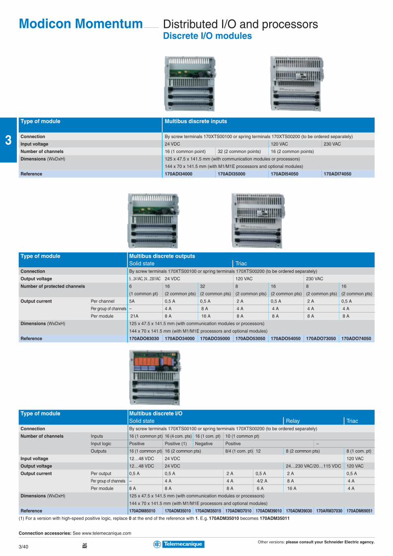
Other versions: please consult your Schneider Electric agency.3/40
3
Distributed I/O and processorsDiscrete I/O modules
Type of module Multibus discrete inputs
Connection By screw terminals 170XTS00100 or spring terminals 170XTS00200 (to be ordered separately)
Input voltage 24 VDC 120 VAC 230 VAC
Number of channels 16 (1 common point) 32 (2 common points) 16 (2 common points)
Dimensions (WxDxH) 125 x 47.5 x 141.5 mm (with communication modules or processors)
144 x 70 x 141.5 mm (with M1/M1E processors and optional modules)
Reference 170ADI34000 170ADI35000 170ADI54050 170ADI74050
Type of module Multibus discrete outputsSolid state Triac
Connection By screw terminals 170XTS00100 or spring terminals 170XTS00200 (to be ordered separately)
Output voltage 5…24 VAC, 24…230 VAC 24 VDC 120 VAC 230 VAC
Number of protected channels 6 16 32 8 16 8 16
(1 common pt) (2 common pts) (2 common pts) (2 common pts) (2 common pts) (2 common pts) (2 common pts)
Output current Per channel 5A 0,5 A 0,5 A 2 A 0,5 A 2 A 0,5 A
Per group of channels – 4 A 8 A 4 A 4 A 4 A 4 A
Per module 21A 8 A 16 A 8 A 8 A 8 A 8 A
Dimensions (WxDxH) 125 x 47.5 x 141.5 mm (with communication modules or processors)
144 x 70 x 141.5 mm (with M1/M1E processors and optional modules)
Reference 170ADO83030 170ADO34000 170ADO35000 170ADO53050 170ADO54050 170ADO73050 170ADO74050
Type of module Multibus discrete I/OSolid state Relay Triac
Connection By screw terminals 170XTS00100 or spring terminals 170XTS00200 (to be ordered separately)
Number of channels Inputs 16 (1 common pt) 16 (4 com. pts) 16 (1 com. pt) 10 (1 common pt)
Input logic Positive Positive (1) Negative Positive –
Outputs 16 (1 common pt) 16 (2 common pts) 8/4 (1 com. pt) 12 8 (2 common pts) 8 (1 com. pt)
Input voltage 12…48 VDC 24 VDC 120 VAC
Output voltage 12…48 VDC 24 VDC 24…230 VAC/20…115 VDC 120 VAC
Output current Per output 0,5 A 0,5 A 2 A 0,5 A 2 A 0,5 A
Per group of channels – 4 A 4 A 4/2 A 8 A 4 A
Per module 8 A 8 A 8 A 6 A 16 A 4 A
Dimensions (WxDxH) 125 x 47.5 x 141.5 mm (with communication modules or processors)
144 x 70 x 141.5 mm (with M1/M1E processors and optional modules)
Reference 170ADM85010 170ADM35010 170ADM35015 170ADM37010 170ADM39010 170ADM39030 170ARM37030 170ADM69051
(1) For a version with high-speed positive logic, replace 0 at the end of the reference with 1. E.g. 170ADM35010 becomes 170ADM35011
Connection accessories: See www.telemecanique.com
Modicon Momentum

Other versions: please consult your Schneider Electric agency.3/41
3
Analog I/O modules
Type of module Multibus analog inputs
Connection By screw terminals 170XTS00100 or spring terminals 170XTS00200 (to be ordered separately)
Number of channels 8 isolated 16 with common point 4 isolated
Input signal ± 5 V, ± 10 V, ± 20 mA, ± 5 V, ± 10 V, 4...20 mA Multi-range ± 25 mV, ± 10 mV
1…5 V, 4…20 mA (1)
Resolution 14 bits + sign, 15 bits unipolar 12 bits + sign 15 bits + sign
Dimensions (WxDxH) 125 x 47.5 x 141.5 mm (with communication modules or processors)
144 x 70 x 141.5 mm (with M1/M1E processors and optional modules)
Reference 170AAI03000 170AAI14000 170AAI52040
(1) Temperature probe: Pt 100, Pt 1000, Ni 100, Ni 1000, Thermocouple: B, E, J, K, N, R, S, T.
Type of module Multibus analog outputs Analog I/O andmultibus discrete I/O
Connection By screw terminals 140XTS00200 (to be ordered separately)
Number of channels Inputs – 4 differential + 4 discrete 6 with com pt + 8 discrete (24 VDC)
Outputs 4 2 + 2 discrete (24VDC) 4 with com pt + 8 discrete (24 VDC)
Input signal ± 10 V, 0...20 mA ± 10 V, 4...20 mA ± 5 V, ± 10 V, ± 20 mA, 0…10 V ± 10 V
1…5 V, 4…20 mA
Output signal – ± 10 V, 4...20 mA 0…10 V ± 10 V
Resolution 12 bits + sign 12...14 bits dep. on signal 14 bits 14 bits
Dimensions (WxDxH) 125 x 47.5 x 141.5 mm (with communication modules or processors)
144 x 70 x 141.5 mm (with M1/M1E processors and optional modules)
Reference 170AAO12000 170AAO92100 170AMM09000 170ANR12090 170ANR12091
Application-specific I/O modules
Type of module High-speed counter Discrete I/Owith Modbus port
Type of inputs for Incremental or absolute encoders RS 485 Modbus port
Operating voltage 24 VDC 120 VAC
Counting frequency 200 kHz –
Number of channels 2 independent –
Number of discrete I/O 2 x 3 inputs/2 x 2 outputs 6 inputs/3 outputs
Dimensions (WxDxH) 125 x 47.5 x 141.5 mm (with communication modules or M1/M1E processors)
144 x 70 x 141.5 mm (with M1/M1E processors and optional modules)
Reference 170AEC92000 170ADM54080
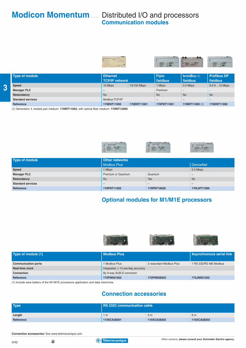
Other versions: please consult your Schneider Electric agency.3/42
3
Distributed I/O and processorsCommunication modules
Type of module Ethernet Fipio INTERBUS (1) Profibus DPTCP/IP network fieldbus fieldbus fieldbus
Speed 10 Mbps 10/100 Mbps 1 Mbps 0.5 Mbps 9.6 K…12 Mbps
Manager PLC – Premium - -
Redundancy No No No No
Standard services Modbus TCP/IP – – –
Reference 170ENT11002 170ENT11001 170FNT11001 170INT11000 (1) 170DNT11000
(1) Generation 4, twisted pair medium: 170INT11003, with optical fiber medium: 170INT12000
Type of module Other networksModbus Plus DeviceNet
Speed 1 Mbps 0.5 Mbps
Manager PLC Premium or Quantum Quantum –
Redundancy No Yes No
Standard services – – –
Reference 170PNT11020 170PNT16020 170LNT71000
Optional modules for M1/M1E processors
Type of module (1) Modbus Plus Asynchronous serial link
Communication ports 1 Modbus Plus 2 redundant Modbus Plus 1 RS 232/RS 485 Modbus
Real-time clock Integrated, ± 13 sec/day accuracy
Connection By 9-way SUB-D connector
Reference 172PNN21022 172PNN26022 172JNN21032
(1) Include save battery of the M1/M1E processors application and data memories.
Connection accessories
Type RS 232C communication cable
Length 1 m 3 m 6 m
Reference 110XCA28201 110XCA28202 110XCA28203
Connection accessories: See www.telemecanique.com
Modicon Momentum
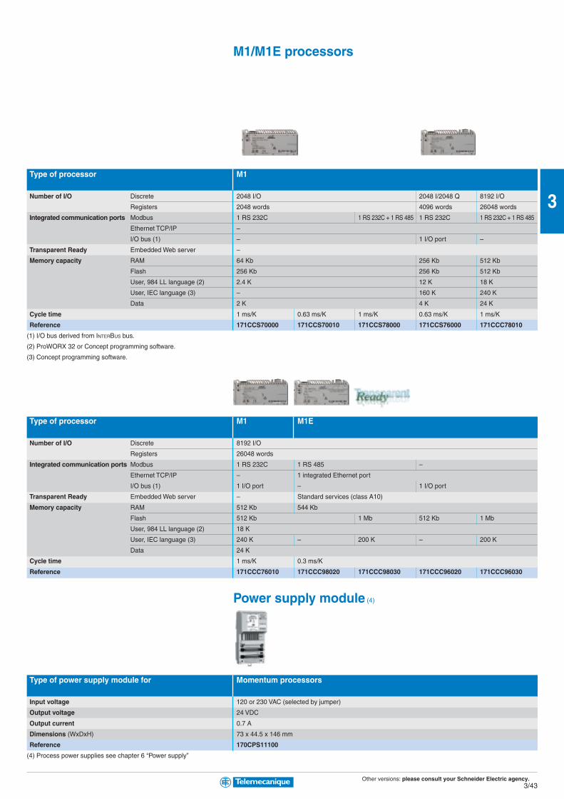
Other versions: please consult your Schneider Electric agency.3/43
3
M1/M1E processors
Type of processor M1
Number of I/O Discrete 2048 I/O 2048 I/2048 Q 8192 I/O
Registers 2048 words 4096 words 26048 words
Integrated communication ports Modbus 1 RS 232C 1 RS 232C + 1 RS 485 1 RS 232C 1 RS 232C + 1 RS 485
Ethernet TCP/IP –
I/O bus (1) – 1 I/O port –
Transparent Ready Embedded Web server –
Memory capacity RAM 64 Kb 256 Kb 512 Kb
Flash 256 Kb 256 Kb 512 Kb
User, 984 LL language (2) 2.4 K 12 K 18 K
User, IEC language (3) – 160 K 240 K
Data 2 K 4 K 24 K
Cycle time 1 ms/K 0.63 ms/K 1 ms/K 0.63 ms/K 1 ms/K
Reference 171CCS70000 171CCS70010 171CCS78000 171CCS76000 171CCC78010
(1) I/O bus derived from INTERBUS bus.
(2) ProWORX 32 or Concept programming software.
(3) Concept programming software.
Type of processor M1 M1E
Number of I/O Discrete 8192 I/O
Registers 26048 words
Integrated communication ports Modbus 1 RS 232C 1 RS 485 –
Ethernet TCP/IP – 1 integrated Ethernet port
I/O bus (1) 1 I/O port – 1 I/O port
Transparent Ready Embedded Web server – Standard services (class A10)
Memory capacity RAM 512 Kb 544 Kb
Flash 512 Kb 1 Mb 512 Kb 1 Mb
User, 984 LL language (2) 18 K
User, IEC language (3) 240 K – 200 K – 200 K
Data 24 K
Cycle time 1 ms/K 0.3 ms/K
Reference 171CCC76010 171CCC98020 171CCC98030 171CCC96020 171CCC96030
Power supply module (4)
Type of power supply module for Momentum processors
Input voltage 120 or 230 VAC (selected by jumper)
Output voltage 24 VDC
Output current 0.7 A
Dimensions (WxDxH) 73 x 44.5 x 146 mm
Reference 170CPS11100
(4) Process power supplies see chapter 6 “Power supply”
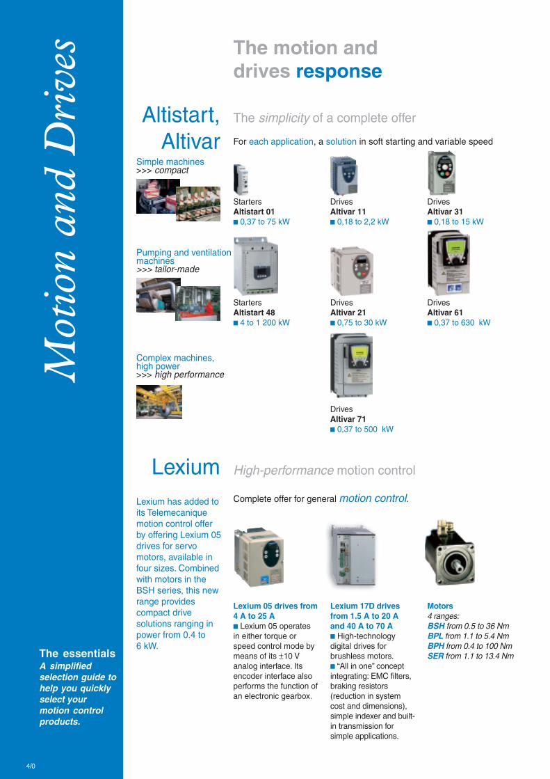
Mot
ion
and
Dri
ves
The essentialsA simplifiedselection guide tohelp you quicklyselect yourmotion controlproducts.
The motion anddrives response
High-performance motion controlLexiumLexium has added toits Telemecaniquemotion control offerby offering Lexium 05drives for servomotors, available infour sizes. Combinedwith motors in theBSH series, this newrange providescompact drivesolutions ranging inpower from 0.4 to6 kW.
Complete offer for general motion control.
Lexium 17D drivesfrom 1.5 A to 20 Aand 40 A to 70 Ab High-technologydigital drives forbrushless motors.b “All in one” conceptintegrating: EMC filters,braking resistors(reduction in systemcost and dimensions),simple indexer and built-in transmission forsimple applications.
Motors4 ranges:BSH from 0.5 to 36 NmBPL from 1.1 to 5.4 NmBPH from 0.4 to 100 NmSER from 1.1 to 13.4 Nm
Lexium 05 drives from4 A to 25 Ab Lexium 05 operatesin either torque orspeed control mode bymeans of its ±10 Vanalog interface. Itsencoder interface alsoperforms the function ofan electronic gearbox.
The simplicity of a complete offerAltistart,Altivar For each application, a solution in soft starting and variable speed
StartersAltistart 01b 0,37 to 75 kW
DrivesAltivar 11b 0,18 to 2,2 kW
DrivesAltivar 61b 0,37 to 630 kW
StartersAltistart 48b 4 to 1 200 kW
DrivesAltivar 31b 0,18 to 15 kW
DrivesAltivar 71b 0,37 to 500 kW
Complex machines,high power>>> high performance
Simple machines>>> compact
Pumping and ventilationmachines>>> tailor-made
DrivesAltivar 21b 0,75 to 30 kW
4/0
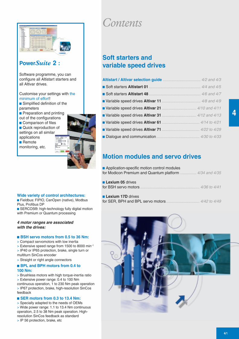
Wide variety of control architectures:b Fieldbus: FIPIO, CanOpen (native), ModbusPlus, Profibus DPb SERCOS®: high-technology fully digital motionwith Premium or Quantum processing
4 motor ranges are associatedwith the drives:
b BSH servo motors from 0.5 to 36 Nm:> Compact servomotors with low inertia> Extensive speed range from 1500 to 8000 min–1
> IP40 or IP65 protection, brake, single turn ormultiturn SinCos encoder> Straight or right angle connectors
b BPL and BPH motors from 0.4 to100 Nm:> Brushless motors with high torque-inertia ratio> Extensive power range: 0.4 to 100 Nmcontinuous operation, 1 to 230 Nm peak operation> IP67 protection, brake, high-resolution SinCosfeedback
b SER motors from 0.3 to 13.4 Nm:> Specially adapted to the needs of OEMs> Wide power range: 1.1 to 13.4 Nm continuousoperation, 2.5 to 38 Nm peak operation. High-resolution SinCos feedback as standard> IP 56 protection, brake, etc
PowerSuite 2 :
Software programme, you canconfigure all Altistart starters andall Altivar drives.
Customise your settings with theminimum of effort!b Simplified definition of theparametersb Preparation and printingout of the configurationsb Comparison of filesb Quick reproduction ofsettings on all similarapplicationsb Remotemonitoring, etc.
4/1
4
1/1
Contents
Soft starters andvariable speed drives
Altistart / Altivar selection guide ................................... 4/2 and 4/3
b Soft starters Altistart 01 ................................................ 4/4 and 4/5
b Soft starters Altistart 48 ................................................ 4/6 and 4/7
b Variable speed drives Altivar 11 .................................... 4/8 and 4/9
b Variable speed drives Altivar 21 ................................ 4/10 and 4/11
b Variable speed drives Altivar 31 ................................ 4/12 and 4/13
b Variable speed drives Altivar 61 ................................... 4/14 to 4/21
b Variable speed drives Altivar 71 ................................... 4/22 to 4/29
b Dialogue and communication ........................................ 4/30 to 4/33
Motion modules and servo drives
b Application-specific motion control modulesfor Modicon Premium and Quantum platform ............... 4/34 and 4/35
b Lexium 05 drivesfor BSH servo motors ....................................................... 4/36 to 4/41
b Lexium 17D drivesfor SER, BPH and BPL servo motors ............................... 4/42 to 4/49

Other versions: Please consult your Schneider Electric sales office.4/2
4
Selection guide
Type of machine Simple machines
Starters/drives Variable speed drives
Altistart 01 Altivar 11 Altivar 31
Single phase 110…480 V Single phase 100…120 V Single phase 200…240 V
Three phase 110…690 V Single phase 200…240 V Three phase 200…240 V
Three phase 200…230 V Three phase 380…500 V
Three phase 525…600 V
Motor power 0.37…75 kW 0.18…2.2 kW 0.18…15 kW
Drive Output frequency – 0.5…200 Hz 0.5…500 Hz
Type of control Asynchronous motor – Sensorless flux vector control
Synchronous motor – – –
Transient overtorque –
nominal motor
FunctionsNumber of functions 1 26 50
Number of preset speeds – 4 16
Number Analog inputs – 1 3
of I/O Logic inputs 3 4 6
Analog outputs – – 1
Logic outputs 1 1 –
Relay outputs 1 1 2
Communication Integrated – – Modbus and CANopen
Available as an option – DeviceNet, Ethernet TCP/IP,
Fipio, Profibus DP
Cards (available as an option) – – –
Standards and certifications IEC/EN 60947-4/2 EN 50178, EN 61800-3 EN 50178, EN 61800-3
C-TICK - CSA - UL EN 55011 - EN 55022 EN 55011 - EN 55022:
CE - CCC class B and class A gr.1 class A, class B
NOM 117 - C-TICK - CSA with option
UL - N998 - CE C-TICK - UL - N998 - CE - CSA
pages 4/4-4/5 pages 4/8-4/9 pages 4/12-4/13
Combined with TeSys model U
starter-controller
Soft starters and softstart/soft stop units
Supply voltage ranges for 50/60 Hz line supply
150...170% of torque 170...200% of the nominal motor torque

Other versions: Please consult your Schneider Electric sales office.4/3
4
Variable speed drives Variable speed drivesBuilding (HVAC) (1) Industry
Altistart 48 Altivar 21 Altivar 61 Altivar 71
Three phase 230…415 V Three phase 200…240 V Single phase 200…240 V Single phase 200…240 V
Three phase 208…690 V Three phase 380…480 V Three phase 200…240 V Three phase 200…240 V
Three phase 380…480 V Three phase 380…480 V
4…1200 kW 0.75…30 kW 0.37…630 kW 0.37…500 kW
– 0.5…200 Hz 0.5…1600 Hz up to 37 kW 0.1…1600 Hz up to 37 kW
0.5…500 Hz from 45 to 630 kW 0.1…500 Hz from 45 to 500 kW
TCS
(Torque Control System)
– – – Vector control without speed feedback
– 200% of the nominal motor torque for 2 s
170% for 60 seconds
36 50 > 150 > 150
– 8 16 16
1 PTC probe 2 2…4 2…4
4 3 6…20 6…20
1 1 1…3 1…3
2 – 0…8 0…8
3 2 2…4 2…4
Modbus Modbus Modbus and CANopen Modbus and CANopen
DeviceNet, Ethernet TCP/IP, LonWorks, METASYS N2, APOGEE FLN, Ethernet TCP/IP, Fipio, Modbus Plus, INTERBUS, Ethernet TCP/IP, Modbus/Uni-Telway, Fipio,
Fipio, Profibus DP BACnet Profibus DP, Modbus/Uni-Telway, DeviceNet, Modbus Plus, Profibus DP, DeviceNet, INTERBUS
LonWorks, METASYS N2, APOGEE FLN, BACnet
– – I/O extension cards Encoder interface card
“Controller Inside” programmable card, I/O extension card
multi-pump cards “Controller Inside” programmable card
IEC/EN 60947-4-2 EN 50178, IEC/EN 61800-3 IEC/EN 61800-5-1,
EMC class A and B EN 55011, EN 55022: IEC/EN 61800-3 (environments 1 and 2, C1 to C3)
DNV - C-TICK - GOST class A, class B with option EN 55011, EN 55022,
CCIB - NOM - UL - CE CE, UL, C-Tick, N998 IEC/EN 61000-4-2/4-3/4-4/4-5/4-6/4-11
CCC - CSA CE, UL, CSA, DNV, C-Tick, NOM 117, GOST
pages 4/6-4/7 pages 4/10-4/11 pages 4/14-4/21 pages 4/22-4/29
(1) Heating Ventilation Air Conditioning
Soft start/soft stop units
Pumping andventilation machines
Complex, high-powermachines
kn2 quadratic ratio, sensorless flux vector
control, voltage/frequency ratio
(2 or 5 points), energy saving ratio
kn2 quadratic ratio, flux vector control with or
without sensor, voltage/frequency ratio
(2 or 5 points), energy saving ratio
Flux vector control with or without sensor,
voltage/frequency ratio
(2 or 5 points), ENA System
Transient overload: 110…120% of the
nominal drive current for 60 seconds
Transient overload: 110% of the nominal
drive current for 60 seconds

Other versions: Please consult your Schneider Electric sales office.4/4
4
Type of starter Soft starters Soft start/soft stop unitsMotor power 0.37 to 11 kW 0.75 to 15 kWDegree of protection IP20
Peak current reduction No (1 controlled phase) Yes (2 controlled phases)
Adjustable starting time 1…5 s 1…10 s
Adjustable stopping time No: freewheel stop Yes: 1... 10 s.
Adjustable starting torque 30…80% of DOL motor starting torque
Logic inputs – 3 logic inputs (start, stop and startup boost)
Logic outputs – 1 logic output
Relay outputs – 1 relay output
Control supply voltage 110... 240 VAC ± 10%, 24 VDC ± 10% Built into the starter
Supply voltage Single phase 110…230 V
Motor power
230 V Nominal current
kW (IcL)
0.37 3 A ATS01N103FT
0.75 6 A ATS01N106FT
1.1 9 A ATS01N109FT
1.5 12 A ATS01N112FT
2.2 25 A ATS01N112FT
Supply voltage Three phase 110…230 V Three phase 200…240 V Three phase 380…415 V Three phase 440…480 V
Motor power
210 V 230 V 400 V 460 V Nominal current
HP kW HP kW HP (IcL)
– 0.37-0.55 0.5/– 1.1 0.5-1.5 3 A ATS01N103FT – – –
0.5 0.75-1.1 1-1.5 2.2-3 2-3 6 A ATS01N106FT ATS01N206LU ATS01N206QN ATS01N206RT
1 1.5 2 4 5 9 A ATS01N109FT ATS01N209LU ATS01N209QN ATS01N209RT
1.5 2.2 3 5.5 7.5 12 A ATS01N112FT ATS01N212LU ATS01N212QN ATS01N212RT
– 4-5.5 5-7.5 7.5-11 10-15 22 A – ATS01N222LU ATS01N222QN ATS01N222RT
2-3 3-4-5.5 5-7.5 7.5-9-11 10-15 25A ATS01N112FT – – –
– 7,5 10 15 20 32 A – ATS01N232LU ATS01N232QN ATS01N232RT
Altistart 010.37…75 kW
Simple machinesStarters
Dimensions (in mm) width x height x depth
ATS01 N103FT/N106 FT 22.5 x 100 x 100
N109FT/N112 FT/N125 FT45 x 124 x 130
N206pp/N209pp / N212pp
N222pp/N232pp 45 x 154 x 130

Other versions: Please consult your Schneider Electric sales office.4/5
4
Starters
Type of starter Soft start/soft stop unitsMotor power 15 to 75 kWDegree of protection IP20 on front panel
Peak current reduction Yes
Adjustable starting and stopping times 1... 25 s
Adjustable starting torque 30.... 80% of DOL motor starting torque
Logic inputs 2 logic inputs (run and stop)
Relay outputs 1 relay output
Control supply voltage 110 VDC ± 10% Built into the starter
Supply voltage Three phase 230…690 V Three phase 400 V
Motor power
230 V 400 V 460 V 690 V Nominal current
kW HP kW HP HP kW (IcL)
7.5 10 15 15 20 30 32 A ATS01N230LY –
11 15 22 25 30 37 44 A ATS01N244LY ATS01N244Q
18.5 25 37 40 50 55 72 A ATS01N272LY ATS01N272Q
22 30 45 50 60 75 85 A ATS01N285LY ATS01N285Q
Starters with TeSys model U
Type of starter Soft start/soft stop unitsMotor power 0.75 to 15 kWDegree of protection IP20
Peak current reduction Yes
Adjustable starting and stopping times 1…10 s
Adjustable starting torque 30.... 80% of DOL motor starting torque
Logic inputs 3 logic inputs (start, stop and startup boost)
Logic outputs 1 logic output
Relay outputs 1 relay output
Control supply voltage Built into the starter
References
Power base between ATSU and
TeSys model U
Supply voltage Three phase 200…480 V
Motor power
230 V 400 V 460 V
kW HP kW HP
0.75 1 1.5 2 6 A ATSU01N206LT LUB12 LUCppppp05BL VW3G4104
1.1 1.5 2.2 3 6 A ATSU01N206LT LUB12 LUCppppp12BL
1.5 2 3 – 9 A ATSU01N209LT LUB12 LUCppppp12BL VW3G4104
– 4 5 9 A ATSU01N209LT LUB12 LUCppppp12BL
2,2 3 – – 12 ATSU01N212LT LUB12 LUCppppp12BL VW3G4104
3 – 5.5 7.5 12 A ATSU01N212LT LUB32 LUCppppp18BL
4 5 7.5 10 22 A ATSU01N222LT LUB32 LUCppppp18BL VW3G4104
5.5 7.5 11 15 22 A ATSU01N222LT LUB32 LUCppppp32BL
7.5 10 15 20 32 A ATSU01N232LT LUB32 LUCppppp32BL VW3G4104
(1) To compose your reference, replace ppppp in the reference with: «A” for a standard control unit, “M” for a multifunction unit and “B” for an advanced unit.
Dimensions (in mm) width x height x depth
ATSU01 N206LT/N209LT/N212LT 45 x 124 x 130
N222LT/N232LT 45 x 154 x 130
Dimensions (in mm) width x height x depth
ATS01 N230pp/N244pp 180 x 146 x 126
N272pp/N285pp 180 x 254.5 x 126
Soft start/soft stop units TeSys model U starter-controller Power connector
Control unit (1)
Nominal
current (IcL)

Other versions: Please consult your Schneider Electric sales office.4/6
4
Altistart 484…1200 kW
Pumping and ventilation machinesSoft start/soft stop units
Supply voltage Three phase 230…415 V (1)
Type of application Standard Severe (2)
Starter control supply voltage 220…415 V
Protection Degree of protection IP20: ATS48D17p to ATS48C11p starters
IP00: ATS48C14p to ATS48M12p starters
Motor thermal protection Class 10 Class 20
EMC Class A On all starters
Class B On all starters up to 170 A
Starting mode Torque control (patented TCS: Torque Control System)
I/O Analog inputs 1 PTC probe
Logic inputs 4 logic inputs, 2 of which are configurable
Logic outputs 2 configurable logic outputs
Analog outputs 1 analog output
Relay outputs 3 relay outputs, 2 of which are configurable
Dialogue Integrated or remote display terminal, or PowerSuite software workshop (3)
Communication (4) Integrated Modbus
Available as an option DeviceNet, Ethernet TCP/IP, Fipio, Profibus DP
Motor power
230 V 400 V Nominal current
kW kW (IcL)
3 5.5 12 A – ATS48D17Q Size A
4 7.5 17 A ATS48D17Q Size A ATS48D22Q Size A
5.5 11 22 A ATS48D22Q Size A ATS48D32Q Size A
7.5 15 32 A ATS48D32Q Size A ATS48D38Q Size A
9 18.5 38 A ATS48D38Q Size A ATS48D47Q Size A
11 22 47 A ATS48D47Q Size A ATS48D62Q Size B
15 30 62 A ATS48D62Q Size B ATS48D75Q Size B
18.5 37 75 A ATS48D75Q Size B ATS48D88Q Size B
22 45 88 A ATS48D88Q Size B ATS48C11Q Size B
30 55 110 A ATS48C11Q Size B ATS48C14Q Size C
37 75 140 A ATS48C14Q Size C ATS48C17Q Size C
45 90 170 A ATS48C17Q Size C ATS48C21Q Size D
55 110 210 A ATS48C21Q Size D ATS48C25Q Size D
75 132 250 A ATS48C25Q Size D ATS48C32Q Size D
90 160 320 A ATS48C32Q Size D ATS48C41Q Size E
110 220 410 A ATS48C41Q Size E ATS48C48Q Size E
132 250 480 A ATS48C48Q Size E ATS48C59Q Size E
160 315 590 A ATS48C59Q Size E ATS48C66Q Size E
– 355 660 A ATS48C66Q Size E ATS48C79Q Size F
220 400 790 A ATS48C79Q Size F ATS48M10Q Size F
250 500 1000 A ATS48M10Q Size F ATS48M12Q Size F
355 630 1200 A ATS48M12Q Size F –
(1) Possible to connect the starter in the motor delta connection
(2) Starting time greater than 30 seconds (fans, high inertia machines and compressors)
(3) (4) PowerSuite software and communication protocols, see page 4/30
Accessory
Accessory Remote display terminal
Reference VW3G48101
Dimensions (in mm) width x height x depth
ATS48 D17Q to D47Q Size A: 160 x 275 x 190
D62Q to C11Q Size B: 190 x 290 x 235
C14Q to C17Q Size C: 200 x 340 x 265
C21Q to C32Q Size D: 320 x 380 x 265
C41Q to C66Q Size E: 400 x 670 x 300
C79Q to M12Q Size F: 770 x 890 x 315

Other versions: Please consult your Schneider Electric sales office.4/7
4
Soft start/soft stop units
Supply voltage Three phase 208…690 V (1)
Type of application Standard Severe (2)
Starter control supply voltage 110…230 V
Characteristics Identical to 230…415 V starters
Motor power
208 V 230 V 460 V 575 V 230 V 400 V 440 V 500 V 525 V 660 V 690 V
HP kW
2 3 7.5 10 3 5.5 5.5 7.5 7.5 9 11 12 A – ATS48D17Y Size A
3 5 10 15 4 7.5 7.5 9 9 11 15 17 A ATS48D17Y Size A ATS48D22Y Size A
5 7.5 15 20 5.5 11 11 11 11 15 18.5 22 A ATS48D22Y Size A ATS48D32Y Size A
7.5 10 20 25 7.5 15 15 18.5 18.5 22 22 32 A ATS48D32Y Size A ATS48D38Y Size A
10 – 25 30 9 18.5 18.5 22 22 30 30 38 A ATS48D38Y Size A ATS48D47Y Size A
– 15 30 40 11 22 22 30 30 37 37 47 A ATS48D47Y Size A ATS48D62Y Size B
15 20 40 50 15 30 30 37 37 45 45 62 A ATS48D62Y Size B ATS48D75Y Size B
20 25 50 60 18.5 37 37 45 45 55 55 75 A ATS48D75Y Size B ATS48D88Y Size B
25 30 60 75 22 45 45 55 55 75 75 88 A ATS48D88Y Size B ATS48C11Y Size B
30 40 75 100 30 55 55 75 75 90 90 110 A ATS48C11Y Size B ATS48C14Y Size C
40 50 100 125 37 75 75 90 90 110 110 140 A ATS48C14Y Size C ATS48C17Y Size C
50 60 125 150 45 90 90 110 110 132 160 170 A ATS48C17Y Size C ATS48C21Y Size D
60 75 150 200 55 110 110 132 132 160 200 210 A ATS48C21Y Size D ATS48C25Y Size D
75 100 200 250 75 132 132 160 160 220 250 250 A ATS48C25Y Size D ATS48C32Y Size D
100 125 250 300 90 160 160 220 220 250 315 320 A ATS48C32Y Size D ATS48C41Y Size E
125 150 300 350 110 220 220 250 250 355 400 410 A ATS48C41Y Size E ATS48C48Y Size E
150 – 350 400 132 250 250 315 315 400 500 480 A ATS48C48Y Size E ATS48C59Y Size E
– 200 400 500 160 315 355 400 400 560 560 590 A ATS48C59Y Size E ATS48C66Y Size E
200 250 500 600 – 355 400 – – 630 630 660 A ATS48C66Y Size E ATS48C79Y Size F
250 300 600 800 220 400 500 500 500 710 710 790 A ATS48C79Y Size F ATS48M10Y Size F
350 350 800 1000 250 500 630 630 630 900 900 1000 A ATS48M10Y Size F ATS48M12Y Size F
400 455 1000 1200 355 630 710 800 800 – – 1200 A ATS48M12Y Size F –
(1) Starter connection in the motor delta connection: add “S316” at the end of the reference
Line chokes
Degree of protection IP20 IP00
References Starter ATS48 D17p D75p to C14p C41p to C48p
Choke VZ1L015UM17T VZ1L150U170T VZ1L530U045T
Type of starter ATS48 D22p C17p to C25p C59p to M10p
Choke VZ1L030U800T VZ1L0250U100T VZ1LM10U024T
Type of starter ATS48 D32p and D38p AC32p M12p
Choke VZ1L040U600T VZ1L325U075T VZ1LM14U016T
Type of starter ATS48 D47p and D62p –
Choke VZ1L070U350T
Dimensions (in mm) width x height x depth
ATS48 D17Y to D47Y Size A: 160 x 275 x 190
D62Y to C11Y Size B: 190 x 290 x 235
C14Y to C17Y Size C: 200 x 340 x 265
C21Y to C32Y Size D: 320 x 380 x 265
C41Y to C66Y Size E: 400 x 670 x 300
C79Y to M12Y Size F: 770 x 890 x 315
Nominal
current
(IcL)
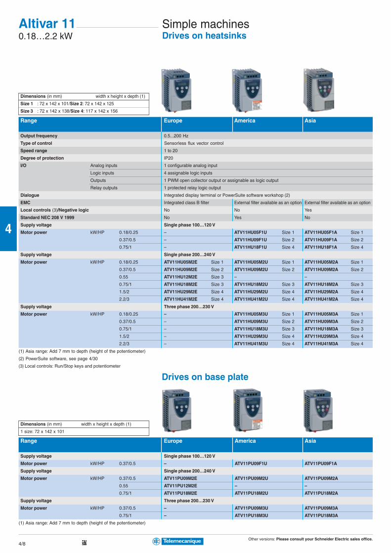
Other versions: Please consult your Schneider Electric sales office.4/8
4
Altivar 110.18…2.2 kW
Simple machinesDrives on heatsinks
Range Europe America Asia
Output frequency 0.5...200 Hz
Type of control Sensorless flux vector control
Speed range 1 to 20
Degree of protection IP20
I/O Analog inputs 1 configurable analog input
Logic inputs 4 assignable logic inputs
Outputs 1 PWM open collector output or assignable as logic output
Relay outputs 1 protected relay logic output
Dialogue Integrated display terminal or PowerSuite software workshop (2)
EMC Integrated class B filter External filter available as an option External filter available as an option
Local controls (3)/Negative logic No No Yes
Standard NEC 208 V 1999 No Yes No
Supply voltage Single phase 100…120 V
Motor power kW/HP 0.18/0.25 – ATV11HU05F1U Size 1 ATV11HU05F1A Size 1
0.37/0.5 – ATV11HU09F1U Size 2 ATV11HU09F1A Size 2
0.75/1 – ATV11HU18F1U Size 4 ATV11HU18F1A Size 4
Supply voltage Single phase 200…240 V
Motor power kW/HP 0.18/0.25 ATV11HU05M2E Size 1 ATV11HU05M2U Size 1 ATV11HU05M2A Size 1
0.37/0.5 ATV11HU09M2E Size 2 ATV11HU09M2U Size 2 ATV11HU09M2A Size 2
0.55 ATV11HU12M2E Size 3 – –
0.75/1 ATV11HU18M2E Size 3 ATV11HU18M2U Size 3 ATV11HU18M2A Size 3
1.5/2 ATV11HU29M2E Size 4 ATV11HU29M2U Size 4 ATV11HU29M2A Size 4
2.2/3 ATV11HU41M2E Size 4 ATV11HU41M2U Size 4 ATV11HU41M2A Size 4
Supply voltage Three phase 200…230 V
Motor power kW/HP 0.18/0.25 – ATV11HU05M3U Size 1 ATV11HU05M3A Size 1
0.37/0.5 – ATV11HU09M3U Size 2 ATV11HU09M3A Size 2
0.75/1 – ATV11HU18M3U Size 3 ATV11HU18M3A Size 3
1.5/2 – ATV11HU29M3U Size 4 ATV11HU29M3A Size 4
2.2/3 – ATV11HU41M3U Size 4 ATV11HU41M3A Size 4
(1) Asia range: Add 7 mm to depth (height of the potentiometer)
(2) PowerSuite software, see page 4/30
(3) Local controls: Run/Stop keys and potentiometer
Drives on base plate
Range Europe America Asia
Supply voltage Single phase 100…120 V
Motor power kW/HP 0.37/0.5 – ATV11PU09F1U ATV11PU09F1A
Supply voltage Single phase 200…240 V
Motor power kW/HP 0.37/0.5 ATV11PU09M2E ATV11PU09M2U ATV11PU09M2A
0.55 ATV11PU12M2E – –
0.75/1 ATV11PU18M2E ATV11PU18M2U ATV11PU18M2A
Supply voltage Three phase 200…230 V
Motor power kW/HP 0.37/0.5 – ATV11PU09M3U ATV11PU09M3A
0.75/1 – ATV11PU18M3U ATV11PU18M3A
(1) Asia range: Add 7 mm to depth (height of the potentiometer)
Dimensions (in mm) width x height x depth (1)
1 size: 72 x 142 x 101
Dimensions (in mm) width x height x depth (1)
Size 1 : 72 x 142 x 101/Size 2: 72 x 142 x 125
Size 3 : 72 x 142 x 138/Size 4: 117 x 142 x 156

Other versions: Please consult your Schneider Electric sales office.4/9
4
Additional EMC input filters
Supply voltage Single phase Three phase100…120 V 200…240 V 200…230 V
Europe range Drive ATV11 – HU05M2E to HU41M2E –
References Filters – Integrated –
America range Drive ATV11 HU05F1U, HU09F1U HU05M2U to HU18M2U HU05M3U to HU18M3U
References Filters VW3A11401 VW3A11401 VW3A11403
Drive ATV11 HU18F1U HU29M2U - HU41M2U HU29M3U to HU41M3U
References Filters VW3A11402 VW3A11402 VW3A11404
Asia range Drive ATV11 HU05F1A - HU09F1A HU05M2A to HU18M2A HU05M3A to HU18M3A
References Filters VW3A11401 VW3A11401 VW3A11403
Drive ATV11 HU18F1A - HU18F1A HU29M2A - HU41M2A HU29M3A to HU41M3A
References Filters VW3A11402 VW3A11402 VW3A11404
Accessories
Accessory
Description Width 35 mm For replacing 2.2 kΩATV08
References Drive ATV11 HU05ppp HU18F1p HU05M2p All ATV11 models All ATV11 models
HU09ppp HU29ppp pHU09M2pp
HU12M2p HU41ppp pU12M2E
HU18pp – pU18M2p
Accessories VW3A11851 VW3A11852 VW3A11811 SZ1RV1202 VW3A11831
Braking resistors and modules...other accessories: Please consult www.Telemecanique.com.
Mounting platesfor
Omega rail
Substitutionplate
Speed referencepotentiometer
Plate for EMC
mounting
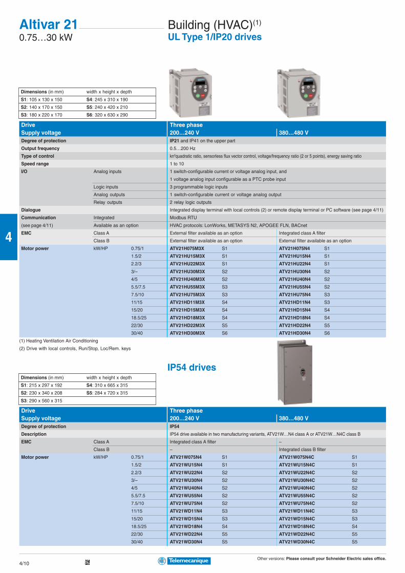
Other versions: Please consult your Schneider Electric sales office.4/10
4
Altivar 210.75…30 kW
Building (HVAC)(1)
UL Type 1/IP20 drives
Drive Three phaseSupply voltage 200…240 V 380…480 VDegree of protection IP21 and IP41 on the upper part
Output frequency 0.5…200 Hz
Type of control kn2quadratic ratio, sensorless flux vector control, voltage/frequency ratio (2 or 5 points), energy saving ratio
Speed range 1 to 10
I/O Analog inputs 1 switch-configurable current or voltage analog input, and
1 voltage analog input configurable as a PTC probe input
Logic inputs 3 programmable logic inputs
Analog outputs 1 switch-configurable current or voltage analog output
Relay outputs 2 relay logic outputs
Dialogue Integrated display terminal with local controls (2) or remote display terminal or PC software (see page 4/11)
Communication Integrated Modbus RTU
(see page 4/11) Available as an option HVAC protocols: LonWorks, METASYS N2, APOGEE FLN, BACnet
EMC Class A External filter available as an option Integrated class A filter
Class B External filter available as an option External filter available as an option
Motor power kW/HP 0.75/1 ATV21H075M3X S1 ATV21H075N4 S1
1.5/2 ATV21HU15M3X S1 ATV21HU15N4 S1
2.2/3 ATV21HU22M3X S1 ATV21HU22N4 S1
3/– ATV21HU30M3X S2 ATV21HU30N4 S2
4/5 ATV21HU40M3X S2 ATV21HU40N4 S2
5.5/7.5 ATV21HU55M3X S3 ATV21HU55N4 S2
7.5/10 ATV21HU75M3X S3 ATV21HU75N4 S3
11/15 ATV21HD11M3X S4 ATV21HD11N4 S3
15/20 ATV21HD15M3X S4 ATV21HD15N4 S4
18.5/25 ATV21HD18M3X S4 ATV21HD18N4 S4
22/30 ATV21HD22M3X S5 ATV21HD22N4 S5
30/40 ATV21HD30M3X S6 ATV21HD30N4 S6
(1) Heating Ventilation Air Conditioning
(2) Drive with local controls, Run/Stop, Loc/Rem. keys
IP54 drives
Drive Three phaseSupply voltage 200…240 V 380…480 VDegree of protection IP54
Description IP54 drive available in two manufacturing variants, ATV21W…N4 class A or ATV21W…N4C class B
EMC Class A Integrated class A filter –
Class B – Integrated class B filter
Motor power kW/HP 0.75/1 ATV21W075N4 S1 ATV21W075N4C S1
1.5/2 ATV21WU15N4 S1 ATV21WU15N4C S1
2.2/3 ATV21WU22N4 S2 ATV21WU22N4C S2
3/– ATV21WU30N4 S2 ATV21WU30N4C S2
4/5 ATV21WU40N4 S2 ATV21WU40N4C S2
5.5/7.5 ATV21WU55N4 S2 ATV21WU55N4C S2
7.5/10 ATV21WU75N4 S2 ATV21WU75N4C S2
11/15 ATV21WD11N4 S3 ATV21WD11N4C S3
15/20 ATV21WD15N4 S3 ATV21WD15N4C S3
18.5/25 ATV21WD18N4 S4 ATV21WD18N4C S4
22/30 ATV21WD22N4 S5 ATV21WD22N4C S5
30/40 ATV21WD30N4 S5 ATV21WD30N4C S5
Dimensions (in mm) width x height x depth
S1: 105 x 130 x 150 S4: 245 x 310 x 190
S2: 140 x 170 x 150 S5: 240 x 420 x 210
S3: 180 x 220 x 170 S6: 320 x 630 x 290
Dimensions (in mm) width x height x depth
S1: 215 x 297 x 192 S4: 310 x 665 x 315
S2: 230 x 340 x 208 S5: 284 x 720 x 315
S3: 290 x 560 x 315

Other versions: Please consult your Schneider Electric sales office.4/11
4
Supply voltage Three phase200…240 V 380…480 V
Maximum length of shielded cable m (1) Class A Class B Class A Class B
References Type of drive ATV21 H075M3X to HU22M3X 50 m 20 m H075N4 to HU22N4 50 m 20 m
Filters VW3A31404 VW3A31404
Type of drive ATV21 HU30M3X and HU40M3X 80 m 50 m HU30N4 to HU55N4 50 m 20 m
Filters VW3A31406 VW3A31406
Type of drive ATV21 HU55M3X and HU75M3X 80 m 50 m HU75N4 and HD11N4 50 m 20 m
Filters VW3A31407 VW3A31407
Type of drive ATV21 HD11M3X to HD18M3X 50 m 1 m HD15N4 and HD18N4 50 m 20 m
Filters VW3A31408 VW3A31409
Type of drive ATV21 HD22M3X 100 m 25 m HD22N4 and HD30N4 200 m 100 m
Filters VW3A4406 VW3A4406
Type of drive ATV21 HD30M3X 100 m 25 m –
Filters VW3A4408
(1) Maximum lengths for shielded cables connecting motors to drives for a switching frequency of 6 to 16 kHz
Communication cardsType LonWorks METASYS N2 APOGEE FLN BACnetStructure Connector
Topology TP/FT-10 (free topology) – – –
Transmission speed 78 Kbps – – –
Diagnostics With LEDs 1 LED on the card: “Service” 1 LED on the card: “COM” (network traffic)
Using the graphic display terminal Command word received/reference received
Description file xif file supplied on CD-ROM – – –
Reference VW3A21312 VW3A21313 VW3A21314 VW3A21315
Remote display terminal
Description The Altivar 21 drive can be connected to a remote display terminal. The display terminal can be mounted on
the door of an enclosure with IP54 protection on the front panel. Max. operating temperature: 40°CSupplied with:
– 1 cable with 2 RJ45 connectors, length 3.6 m
– Seal and screws for IP54 mounting on an enclosure door
Reference VW3A21101
Connection accessoriesModbus bus Splitter box Cables (L = 1 m) T-junction boxes (L = 1 m) Line terminatorDescription 10 RJ45 connectors Equipped with T-junction boxes Adaptation for
and 1 screw terminal 2 RJ45 connectors (with integrated cable) RJ45 connector
Reference LU9GC3 VW3A8306R10 VW3A8306TF10 VW3A8306RC
PC software for Altivar 21 drives
Description It includes various functions such as:
Preparing configurations, setup and maintenance.
It can operate in the following PC environments and configurations:
Microsoft Windows® 98, Microsoft Windows® 2000, Microsoft Windows® XP, Pentium® 233 MHz or more,
hard disk with 10 Mb available, 32 Mb RAM, 256 colour 640 x 480 pixels or higher definition monitor.
Reference VW3A21104
Additional EMC input filters
1 removable 4-way
screw terminal
1 removable 4-way
screw terminal
1 removable 4-way
screw terminal
1 removable 3-way
screw terminal

Other versions: Please consult your Schneider Electric sales office.4/12
4
Altivar 310.18…15 kW
Simple machinesDrives on heatsinks
Supply voltage Single phase Three phase200…240 V 200…240 V 380…500 V
Output frequency 0.5…500 Hz
Type of control Sensorless flux vector control
Speed range 1 to 50
Degree of protection IP31 and IP41 on upper part and IP21 on connection terminals
I/O Analog inputs 3 configurable analog inputs
Logic inputs 6 programmable logic inputs
Analog outputs 1 current analog output (assignable as logic output) and 1 voltage analog output
Relay outputs 2 relay logic outputs
Dialogue Integrated display terminal with or without local controls (1) or PowerSuite software workshop (see page 4/30)
Communication Integrated Modbus and CANopen
(see page 4/30) Available as an option DeviceNet, Ethernet TCP/IP, Fipio, Profibus DP
EMC Class A Integrated class A filter External filter available as an option Integrated class A filter
Class B External filter available as an option
Motor power kW/HP 0.18/0.25 ATV31H018M2 Size 3 ATV31H018M3X Size 1 –
0.37/0.5 ATV31H037M2 Size 3 ATV31H037M3X Size 1 ATV31H037N4 Size 5
0.55/0.75 ATV31H055M2 Size 4 ATV31H055M3X Size 2 ATV31H055N4 Size 5
0.75/1 ATV31H075M2 Size 4 ATV31H075M3X Size 2 ATV31H075N4 Size 6
1.1/1.5 ATV31HU11M2 Size 6 ATV31HU11M3X Size 5 ATV31HU11N4 Size 6
1.5/2 ATV31HU15M2 Size 6 ATV31HU15M3X Size 5 ATV31HU15N4 Size 6
2.2/3 ATV31HU22M2 Size 7 ATV31HU22M3X Size 6 ATV31HU22N4 Size 7
3/– – ATV31HU30M3X Size 7 ATV31HU30N4 Size 7
4/5 – ATV31HU40M3X Size 7 ATV31HU40N4 Size 7
5.5/7.5 – ATV31HU55M3X Size 8 ATV31HU55N4 Size 8
7.5/10 – ATV31HU75M3X Size 8 ATV31HU75N4 Size 8
11/15 – ATV31HD11M3X Size 9 ATV31HD11N4 Size 9
15/20 – ATV31HD15M3X Size 9 ATV31HD15N4 Size 9
(1) For drive with local controls (Run/Stop keys and potentiometer) add an “A” at the end of the reference.
To order a drive intended for spooling applications, add a «T» at the end of the reference.
Enclosed drives
Supply voltage Single phase 200…240 V Three phase 380…500 VDegree of protection IP55
Description Enclosure equipped with an ATV31 drive with external heatsink. Removable covers for adding
1 switch-disconnector or 1 circuit-breaker, 3 buttons and/or LEDs, 1 potentiometer
Motor power kW/HP 0.18/0.25 ATV31C018M2 Size 1 –
0.37/0.5 ATV31C037M2 Size 1 ATV31C037N4 Size 2
0.55/0.75 ATV31C055M2 Size 1 ATV31C055N4 Size 2
0.75/1 ATV31C075M2 Size 1 ATV31C075N4 Size 2
1.1/1.5 ATV31CU11M2 Size 2 ATV31CU11N4 Size 2
1.5/2 ATV31CU15M2 Size 2 ATV31CU15N4 Size 2
2.2/3 ATV31CU22M2 Size 3 ATV31CU22N4 Size 3
3/– – ATV31CU30N4 Size 3
4/5 – ATV31CU40N4 Size 3
5.5/7.5 – ATV31CU55N4 (2) Size 4
7.5/10 – ATV31CU75N4 (2) Size 4
11/15 – ATV31CD11N4 (2) Size 5
15/20 – ATV31CD15N4 (2) Size 5
Drive kit (Altivar 31 drive on metal support plate with EMC filter): Please consult your Schneider Electric sales office. (2) Drive in metal enclosure without cover.
Dimensions (in mm) width x height x depth
Size 1: 210 x 240 x 163 / Size 2: 215 x 297 x 192
Size 3: 230 x 340 x 208 / Size 4: 320 x 512 x 276
Size 5: 440 x 625 x 276
Dimensions (in mm) width x height x depth
Size 1: 72 x 145 x 120 / Size 2: 72 x 145 x 130
Size 3: 72 x 145 x 140 / Size 4: 72 x 145 x 145
Size 5: 105 x 143 x 130 / Size 6: 105 x 143 x 150
Size 7: 140 x 184 x 150 / Size 8: 180 x 232 x 170
Size 9: 245 x 330 x 190
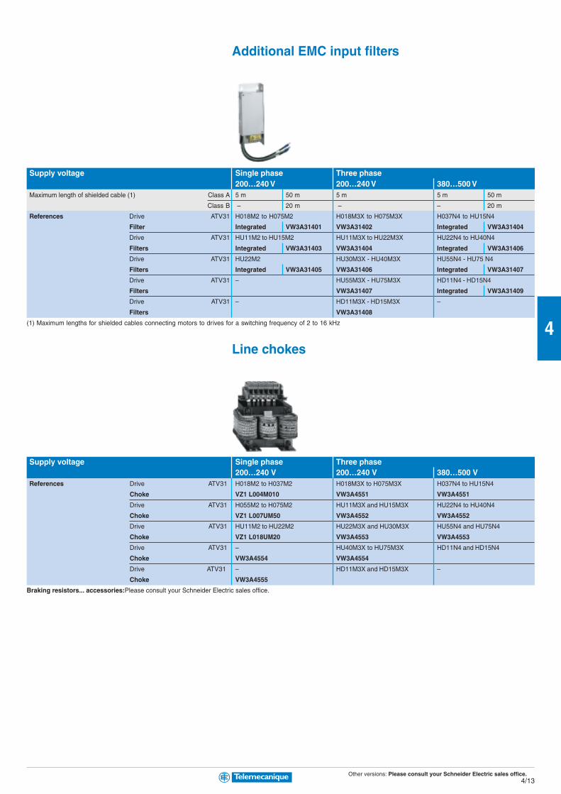
Other versions: Please consult your Schneider Electric sales office.4/13
4
Supply voltage Single phase Three phase200…240 V 200…240 V 380…500 V
Maximum length of shielded cable (1) Class A 5 m 50 m 5 m 5 m 50 m
Class B – 20 m – – 20 m
References Drive ATV31 H018M2 to H075M2 H018M3X to H075M3X H037N4 to HU15N4
Filter Integrated VW3A31401 VW3A31402 Integrated VW3A31404
Drive ATV31 HU11M2 to HU15M2 HU11M3X to HU22M3X HU22N4 to HU40N4
Filters Integrated VW3A31403 VW3A31404 Integrated VW3A31406
Drive ATV31 HU22M2 HU30M3X - HU40M3X HU55N4 - HU75 N4
Filters Integrated VW3A31405 VW3A31406 Integrated VW3A31407
Drive ATV31 – HU55M3X - HU75M3X HD11N4 - HD15N4
Filters VW3A31407 Integrated VW3A31409
Drive ATV31 – HD11M3X - HD15M3X –
Filters VW3A31408
(1) Maximum lengths for shielded cables connecting motors to drives for a switching frequency of 2 to 16 kHz
Line chokes
Supply voltage Single phase Three phase200…240 V 200…240 V 380…500 V
References Drive ATV31 H018M2 to H037M2 H018M3X to H075M3X H037N4 to HU15N4
Choke VZ1 L004M010 VW3A4551 VW3A4551
Drive ATV31 H055M2 to H075M2 HU11M3X and HU15M3X HU22N4 to HU40N4
Choke VZ1 L007UM50 VW3A4552 VW3A4552
Drive ATV31 HU11M2 to HU22M2 HU22M3X and HU30M3X HU55N4 and HU75N4
Choke VZ1 L018UM20 VW3A4553 VW3A4553
Drive ATV31 – HU40M3X to HU75M3X HD11N4 and HD15N4
Choke VW3A4554 VW3A4554
Drive ATV31 – HD11M3X and HD15M3X –
Choke VW3A4555
Braking resistors... accessories:Please consult your Schneider Electric sales office.
Additional EMC input filters

Other versions: Please consult your Schneider Electric sales office.4/14
4
Pumping and ventilation machinesIP21 drives
Altivar 610.37…630 kW
Type of drive Single phase Three phase Three phaseSupply voltage 200…240 V (3) 200…240 V (3) 380…480 V (3)
Degree of protection IP21 for unprotected drives and IP41 on the upper part
Drive Output frequency 0.5…1600 Hz up to 37 kW; 0.5…500 Hz from 45 to 630 kW
Type of control Asynchronous motor kn2 quadratic ratio, flux vector control with or without sensor, voltage/frequency ratio (2 or 5 points), energy saving ratio
Synchronous motor Vector control without speed feedback
Transient overtorque 110% to 120% of the nominal drive current for 60 seconds
Speed range 1…100 in open loop mode
Functions Number of functions > 150
Number of preset speeds 16
Number of I/O Analog inputs 2…4/Logic inputs 6…20
Analog outputs 1…3/Logic outputs 0…8
Relay outputs 2…4
Safety input 1
Dialogue Remote graphic display terminal or PowerSuite software workshop (see pages 4/17 and 4/30)
Communication Integrated Modbus and CANopen(see page 4/30) Available as an option HVAC protocols: LonWorks, BACnet, METASYS N2, APOGEE FLN
Industrial: Ethernet TCP/IP, Modbus/Uni-Telway, Fipio, Modbus Plus, Profibus DP, DeviceNet, INTERBUS
Cards (available as an option) Multi-pump cards, I/O extension cards, “Controller Inside” programmable card
Reduction of current harmonics DC choke integrated or supplied with the product (optional chokes and passive filters, see page 4/18)
EMC Class A Integrated filter
Class B External filter available as an option
Motor power kW/HP 0.37/0.5 ATV61H075M3 S2 – –
0.75/1 ATV61HU15M3 S2 ATV61H075M3 S2 ATV61H075N4 (3) S2
1.5/2 ATV61HU22M3 S3 ATV61HU15M3 S2 ATV61HU15N4 (3) S2
2.2/3 ATV61HU30M3 S3 ATV61HU22M3 S3 ATV61HU22N4 (3) S2
3/– ATV61HU40M3 (1) S3 ATV61HU30M3 S3 ATV61HU30N4 (3) S3
4/5 ATV61HU55M3 (1) S4 ATV61HU40M3 S3 ATV61HU40N4 (3) S3
5.5/7.5 ATV61HU75M3 (1) S5A ATV61HU55M3 S4 ATV61HU55N4 (3) S4
7.5/10 – ATV61HU75M3 S5A ATV61HU75N4 (3) S4
11/15 – ATV61HD11M3X(2) S5B ATV61HD11N4 (3) S5A
15/20 – ATV61HD15M3X(2) S5B ATV61HD15N4 (3) S5B
18.5/25 – ATV61HD18M3X(2) S6 ATV61HD18N4 (3) S5B
22/30 – ATV61HD22M3X(2) S6 ATV61HD22N4 (3) S6
30/40 – ATV61HD30M3X(2) S7B ATV61HD30N4 (3) S7A
37/50 – ATV61HD37M3X(2) S7B ATV61HD37N4 (3) S7A
45/60 – ATV61HD45M3X(2) S7B ATV61HD45N4 (3) S8
55/75 – ATV61HD55M3X(2) S9 ATV61HD55N4 (3) S8
75/100 – ATV61HD75M3X(2) S9 ATV61HD75N4 (3) S8
90/125 – ATV61HD90M3X(2) S10 ATV61HD90N4 (3) S9
110/150 – – ATV61HC11N4 S9
132/200 – – ATV61HC13N4 S10
160/250 – – ATV61HC16N4 S11
200/300 – – ATV61HC22N4 S12
220/350 – – ATV61HC22N4 S12
250/400 – – ATV61HC25N4 S13
280/450 – – ATV61HC31N4 S13
315/500 – – ATV61HC31N4 S13
355/– – – ATV61HC40N4 S14
400/600 – – ATV61HC40N4 S14
500/700 – – ATV61HC50N4 S14
560/800 – – ATV61HC63N4 S15
630/900 – – ATV61HC63N4 S15
(1) Must be used with a line choke, see page 4/18 (2) Drive supplied without EMC filter
(3) To order a reinforced version of the drive for specific environmental conditions, conforming to IEC 60721-3-3 class 3c2, add S337 at the end of the reference.
E.g. ATV61H075N4S337
Dimensions (in mm) width x height x depth
S2 : 130 x 230 x 175 S3 : 155 x 260 x 187
S4 : 175 x 295 x 187 S5A : 210 x 295 x 213
S5B : 230 x 400 x 213 S6 : 240 x 420 x 236
S7A : 240 x 550 x 266 S7B : 320 x 550 x 266
S8 : 320 x 630 x 290 S9 : 320 x 920 x 377
S10 : 360 x 1022 x 377 S11 : 340 x 1190 x 377
S12 : 440 x 1190 x 377 S13 : 595 x 1190 x 377
S14 : 890 x 1390 x 377 S15 : 1120 x 1390 x 377

Other versions: Please consult your Schneider Electric sales office.4/15
4
Type of drive Three phase Three phase range in ready-assembled enclosure (4)
380…480 V (3) 380…480 VDegree of protection UL Type 12/IP54 IP54 enclosure
Drive Output frequency 0.5…1600 Hz up to 37 kW; 0.5…500 Hz from 45 to 630 kW
Type of control Asynchronous motorkn2 quadratic ratio, flux vector control with or without sensor, voltage/frequency ratio (2 or 5 points), energy saving ratio
Synchronous motor Vector control without speed feedback
Transient overtorque 110% to 120% of the nominal drive current for 60 seconds
Speed range 1…100 in open loop mode
Functions Number of functions > 150
Number of preset speeds 16
Number of I/O Analog inputs 2…4/Logic inputs 6…20
Analog outputs 1…3/Logic outputs 0…8
Relay outputs 2…4
Safety input 1
Dialogue Remote graphic display terminal or PowerSuite software workshop (see page 4/30)
Communication Integrated Modbus and CANopen(see page 4/30) Available as an option HVAC protocols: LonWorks, BACnet, METASYS N2, APOGEE FLN
Industrial: Ethernet TCP/IP, Modbus/Uni-Telway, Fipio, Modbus Plus, Profibus DP, DeviceNet, INTERBUS
Cards (available as an option) Multi-pump cards, I/O extension cards, “Controller Inside” programmable card
Reduction of current harmonics Integrated DC choke (optional chokes and passive filters, see page 4/18)
EMC Class A Integrated filter Integrated filter
Class B Integrated filter External filter available as an option
Motor power kW/HP 0.75/1 ATV61W075N4 SA2 ATV61W075N4C SA2 –
1.5/2 ATV61WU15N4 SA2 ATV61WU15N4C SA2 –
2.2/3 ATV61WU22N4 SA2 ATV61WU22N4C SA2 –
3/– ATV61WU30N4 SA3 ATV61WU30N4C SA3 –
4/5 ATV61WU40N4 SA3 ATV61WU40N4C SA3 –
5.5/7.5 ATV61WU55N4 SB ATV61WU55N4C SB –
7.5/10 ATV61WU75N4 SB ATV61WU75N4C SB –
11/15 ATV61WD11N4 SC ATV61WD11N4C SC –
15/20 ATV61WD15N4 SD ATV61WD15N4C SD –
18.5/25 ATV61WD18N4 SD ATV61WD18N4C SD –
22/30 ATV61WD22N4 SE ATV61WD22N4C SE –
30/40 ATV61WD30N4 SF ATV61WD30N4C SF –
37/50 ATV61WD37N4 SF ATV61WD37N4C SF –
45/60 ATV61WD45N4 SG ATV61WD45N4C SG –
55/75 ATV61WD55N4 SG ATV61WD55N4C SG –
75/100 ATV61WD75N4 SG ATV61WD75N4C SG –
90/125 ATV61WD90N4 SG ATV61WD90N4C SG –
110/150 – – ATV61HC11N4 ATV61E5C11N4 A1
132/200 – – ATV61HC13N4 ATV61E5C13N4 A1
160/250 – – ATV61HC16N4 ATV61E5C16N4 A1
220/350 – – ATV61HC22N4 ATV61E5C22N4 A1
250/400 – – ATV61HC25N4 ATV61E5C25N4F A2
315/500 – – ATV61HC31N4 ATV61E5C31N4F A2
250/400 – – ATV61HC25N4 ATV61E5C25N4 A2
315/500 – – ATV61HC31N4 ATV61E5C31N4 A2
400/600 – – ATV61HC40N4 ATV61E5C40N4 A3
500/700 – – ATV61HC50N4 ATV61E5C50N4 A3
630/900 – – ATV61HC63N4 ATV61E5C63N4 A4
(4) The Altivar 61 range in ready-assembled enclosure consists of:
– An ATV61H… drive
– A switch and fast-acting fuses
– An IP65 remote mounting kit for graphic display terminal
IP54 drivesDimensions (in mm) width x height x depth
ATV61W… ATV61E5C… in enclosure
SA2 : 235 x 490 x 272 A1 : 616 x 2000 x 600
SA3 : 235 x 490 x 286 A2 : 816 x 2000 x 600
SB : 255 x 525 x 286 A3 : 1016 x 2000 x 600
SC : 290 x 560 x 315 A3 : 1220 x 2000 x 600
SD : 310 x 665 x 315 A3 : 2024 x 2000 x 600
SE : 284 x 720 x 315 A4 : 1216 x 2000 x 600
SF : 284 x 880 x 343 A4 : 1820 x 2000 x 600
SG : 362 x 1000 x 364 A4 : 2224 x 2000 x 600
Ready-assembled enclosure with
braking transistor integrated in the
drive
Ready-assembled enclosure with
braking unit in the enclosure
Ready-assembled enclosure
without braking unit

Other versions: Please consult your Schneider Electric sales office.4/16
4
1 relay logic output (“C/O” contact)
4 x 24 VDC positive or negative logic inputs
2 x 24 VDC open collector positive or negative
logic outputs
1 input for PTC probes
1 x 0…20 mA differential current analog input
1 software-configurable voltage (0…10 VDC) or
current (0…20 mA) analog input
2 software-configurable voltage (±10V, 0…10 VDC) or
current (0…20 mA) analog outputs
1 relay logic output (“C/O” contact)
4 x 24 VDC positive or negative logic inputs
2 x 24 VDC open collector positive or negative logic
outputs
1 input for PTC probes
1 frequency control input
Altivar 610.37…630 kW
Type of card I/O extensionLogic Extended
Description
Reference VW3A3201 VW3A3202
“Controller Inside” programmable card
Type of card Programmable “Controller Inside”
Description 10 logic inputs, 2 of which can be used for 2 counters or 4 of which can be used for 2 incremental encoders
2 analog inputs, 6 logic outputs, 2 analog outputs, a master port for the CANopen bus,
a PC port for programming with the PS 1131 software workshop.
Reference VW3A3501
Multi-pump cards
Type of card Multi-pump
Description Ensures compatibility with an ATV61 The card’s 9 operating modes are:
of applications developed for an ATV 38. b OFF: no function is activated. This mode is used in particular during maintenance of the installation.
b Single variable. b Multiple variable. b Single variable with changeover of auxiliary pumps.
b Multiple variable with changeover of auxiliary pumps. b Single variable with limited operating time.
b Multiple variable with limited operating time. b Single variable with changeover of auxiliary pumps
and limited operating time. b Multiple variable with changeover of auxiliary pumps and limited
operating time.
Reference VW3A3502
Description In addition to the existing operating modes, it is possible to develop new applications:
booster station, irrigation, etc.
Reference VW3A3503
Pumping and ventilation machinesI/O extension and specific cards
Can be used to support all
multi-pump applications

Other versions: Please consult your Schneider Electric sales office.4/17
4
Dialogue accessories
Accessory Remote graphic display terminal Remote mounting kit (1)
Description
b All the mechanical fittings
b Fixing accessories
References VW3A1101 VW3A1102
(1) Use a VW3A1104Rpp remote-mounting connection cable, to be ordered separately (please consult the “Soft starters and variable speed drives” catalogue)
Additional EMC input filters
Type of drive Three phase200…240 V 50/60 Hz 380…480 V 50/60 Hz
Maximum length of shielded cable Class A Class B Class A Class B
ATV61H075M3, HU15M3 VW3A4401 100 m 50 m –
ATV61HU22M3…HU40M3 VW3A4402 100 m 50 m –
ATV61HU55M3 VW3A4403 100 m 50 m –
ATV61HU75M3 VW3A4404 100 m 50 m –
ATV61HD11M3X, HD15M3X VW3A4405 200 m 50 m –
ATV61HD18M3X, HD22M3X VW3A4406 200 m 50 m –
ATV61HD30M3X...HD45M3X VW3A4408 200 m 50 m –
ATV61HD55M3X, HD75M3X VW3A4410 100 m 50 m –
ATV61HD90M3X VW3A4411 100 m 50 m –
ATV61p075N4(C)…pU22N4(C) – VW3A4401 100 m 50 m
ATV61pU30N4(C), pU40N4(C) – VW3A4402 100 m 50 m
ATV61pU55N4(C), pU75N4(C) – VW3A4403 100 m 50 m
ATV61pD11N4(C) – VW3A4404 100 m 50 m
ATV61pD15N4(C), pD18N4(C) – VW3A4405 300 m 100 m
ATV61pD22N4(C) – VW3A4406 300 m 100 m
ATV61pD30N4(C), pD37N4(C) – VW3A4407 300 m 100 m
ATV61pD45N4(C)…pD75N4(C) – VW3A4408 300 m 100 m
ATV61pD90N4(C)…HC16N4, ATV61E5C11N4…E5C16N4 – VW3A4410 300 m 50 m
ATV61HC22N4…HC31N4, ATV61E5C22N4…E5C31N4 – VW3A4411 300 m 50 m
ATV61HC40N4, HC50N4, ATV61E5C40N4, E5C50N4 – VW3A4412 300 m 50 m
ATV61HC63N4, ATV61E5C63N4 – VW3A4413 300 m 50 m
p Applies to the following drives: ATV61H…N4, ATV61H…N4C, ATV61W…N4, ATV61W…N4C
The additional EMC input filters can be used to meet therequirements of the EMC “products” standard IEC/EN 61800-3,edition 2, category C2 or C3 in environment 1 or 2.
This display terminal is attached to the front of
the drive.
It includes the integrated 7-segment display
terminal for drives supplied without a graphic
display terminal.
A remote mounting kit for mounting on an
enclosure door with IP54 degree of protection.
It includes:
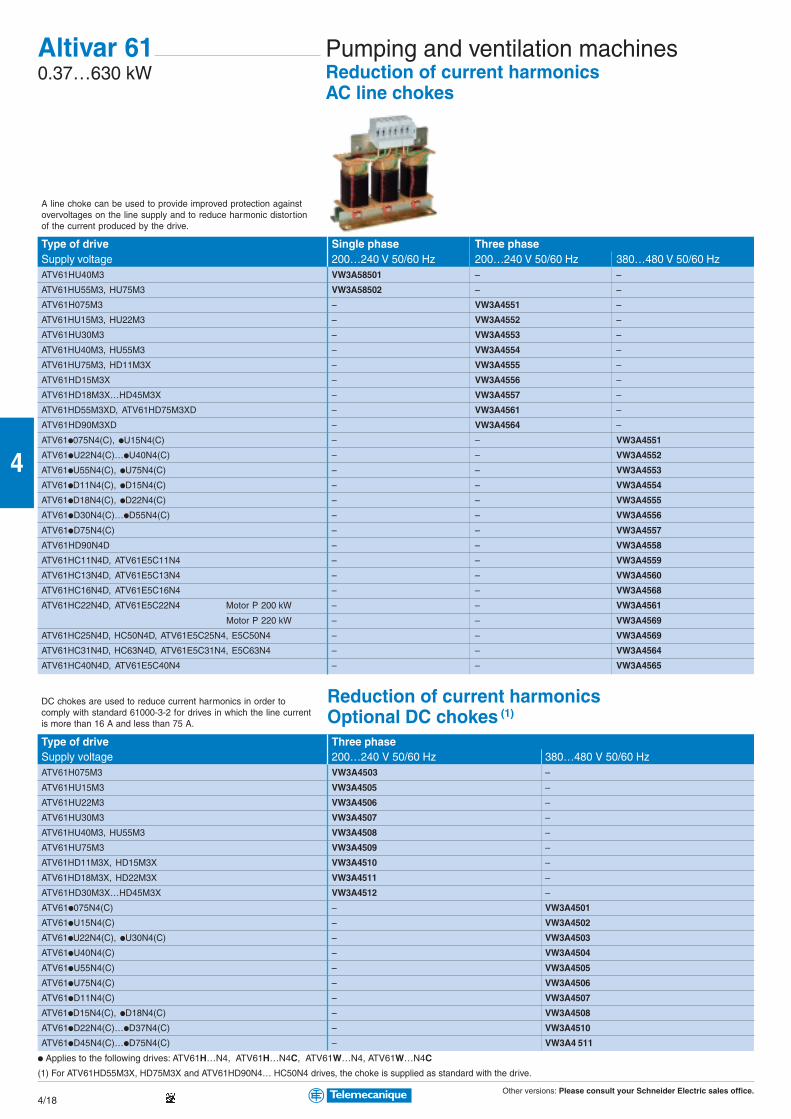
Other versions: Please consult your Schneider Electric sales office.4/18
4
Altivar 610.37…630 kW
Type of drive Single phase Three phaseSupply voltage 200…240 V 50/60 Hz 200…240 V 50/60 Hz 380…480 V 50/60 HzATV61HU40M3 VW3A58501 – –
ATV61HU55M3, HU75M3 VW3A58502 – –
ATV61H075M3 – VW3A4551 –
ATV61HU15M3, HU22M3 – VW3A4552 –
ATV61HU30M3 – VW3A4553 –
ATV61HU40M3, HU55M3 – VW3A4554 –
ATV61HU75M3, HD11M3X – VW3A4555 –
ATV61HD15M3X – VW3A4556 –
ATV61HD18M3X…HD45M3X – VW3A4557 –
ATV61HD55M3XD, ATV61HD75M3XD – VW3A4561 –
ATV61HD90M3XD – VW3A4564 –
ATV61p075N4(C), pU15N4(C) – – VW3A4551
ATV61pU22N4(C)…pU40N4(C) – – VW3A4552
ATV61pU55N4(C), pU75N4(C) – – VW3A4553
ATV61pD11N4(C), pD15N4(C) – – VW3A4554
ATV61pD18N4(C), pD22N4(C) – – VW3A4555
ATV61pD30N4(C)…pD55N4(C) – – VW3A4556
ATV61pD75N4(C) – – VW3A4557
ATV61HD90N4D – – VW3A4558
ATV61HC11N4D, ATV61E5C11N4 – – VW3A4559
ATV61HC13N4D, ATV61E5C13N4 – – VW3A4560
ATV61HC16N4D, ATV61E5C16N4 – – VW3A4568
ATV61HC22N4D, ATV61E5C22N4 Motor P 200 kW – – VW3A4561
Motor P 220 kW – – VW3A4569
ATV61HC25N4D, HC50N4D, ATV61E5C25N4, E5C50N4 – – VW3A4569
ATV61HC31N4D, HC63N4D, ATV61E5C31N4, E5C63N4 – – VW3A4564
ATV61HC40N4D, ATV61E5C40N4 – – VW3A4565
Reduction of current harmonicsOptional DC chokes (1)
Type of drive Three phaseSupply voltage 200…240 V 50/60 Hz 380…480 V 50/60 HzATV61H075M3 VW3A4503 –
ATV61HU15M3 VW3A4505 –
ATV61HU22M3 VW3A4506 –
ATV61HU30M3 VW3A4507 –
ATV61HU40M3, HU55M3 VW3A4508 –
ATV61HU75M3 VW3A4509 –
ATV61HD11M3X, HD15M3X VW3A4510 –
ATV61HD18M3X, HD22M3X VW3A4511 –
ATV61HD30M3X…HD45M3X VW3A4512 –
ATV61p075N4(C) – VW3A4501
ATV61pU15N4(C) – VW3A4502
ATV61pU22N4(C), pU30N4(C) – VW3A4503
ATV61pU40N4(C) – VW3A4504
ATV61pU55N4(C) – VW3A4505
ATV61pU75N4(C) – VW3A4506
ATV61pD11N4(C) – VW3A4507
ATV61pD15N4(C), pD18N4(C) – VW3A4508
ATV61pD22N4(C)…pD37N4(C) – VW3A4510
ATV61pD45N4(C)…pD75N4(C) – VW3A4 511
p Applies to the following drives: ATV61H…N4, ATV61H…N4C, ATV61W…N4, ATV61W…N4C
(1) For ATV61HD55M3X, HD75M3X and ATV61HD90N4… HC50N4 drives, the choke is supplied as standard with the drive.
Pumping and ventilation machinesReduction of current harmonicsAC line chokes
DC chokes are used to reduce current harmonics in order tocomply with standard 61000-3-2 for drives in which the line currentis more than 16 A and less than 75 A.
A line choke can be used to provide improved protection againstovervoltages on the line supply and to reduce harmonic distortionof the current produced by the drive.
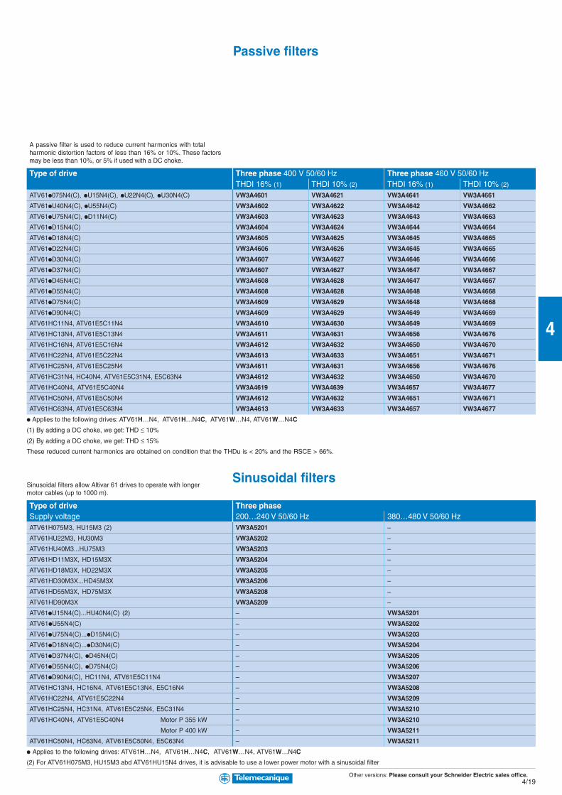
Other versions: Please consult your Schneider Electric sales office.4/19
4
Type of drive Three phase 400 V 50/60 Hz Three phase 460 V 50/60 HzTHDI 16% (1) THDI 10% (2) THDI 16% (1) THDI 10% (2)
ATV61p075N4(C), pU15N4(C), pU22N4(C), pU30N4(C) VW3A4601 VW3A4621 VW3A4641 VW3A4661
ATV61pU40N4(C), pU55N4(C) VW3A4602 VW3A4622 VW3A4642 VW3A4662
ATV61pU75N4(C), pD11N4(C) VW3A4603 VW3A4623 VW3A4643 VW3A4663
ATV61pD15N4(C) VW3A4604 VW3A4624 VW3A4644 VW3A4664
ATV61pD18N4(C) VW3A4605 VW3A4625 VW3A4645 VW3A4665
ATV61pD22N4(C) VW3A4606 VW3A4626 VW3A4645 VW3A4665
ATV61pD30N4(C) VW3A4607 VW3A4627 VW3A4646 VW3A4666
ATV61pD37N4(C) VW3A4607 VW3A4627 VW3A4647 VW3A4667
ATV61pD45N4(C) VW3A4608 VW3A4628 VW3A4647 VW3A4667
ATV61pD55N4(C) VW3A4608 VW3A4628 VW3A4648 VW3A4668
ATV61pD75N4(C) VW3A4609 VW3A4629 VW3A4648 VW3A4668
ATV61pD90N4(C) VW3A4609 VW3A4629 VW3A4649 VW3A4669
ATV61HC11N4, ATV61E5C11N4 VW3A4610 VW3A4630 VW3A4649 VW3A4669
ATV61HC13N4, ATV61E5C13N4 VW3A4611 VW3A4631 VW3A4656 VW3A4676
ATV61HC16N4, ATV61E5C16N4 VW3A4612 VW3A4632 VW3A4650 VW3A4670
ATV61HC22N4, ATV61E5C22N4 VW3A4613 VW3A4633 VW3A4651 VW3A4671
ATV61HC25N4, ATV61E5C25N4 VW3A4611 VW3A4631 VW3A4656 VW3A4676
ATV61HC31N4, HC40N4, ATV61E5C31N4, E5C63N4 VW3A4612 VW3A4632 VW3A4650 VW3A4670
ATV61HC40N4, ATV61E5C40N4 VW3A4619 VW3A4639 VW3A4657 VW3A4677
ATV61HC50N4, ATV61E5C50N4 VW3A4612 VW3A4632 VW3A4651 VW3A4671
ATV61HC63N4, ATV61E5C63N4 VW3A4613 VW3A4633 VW3A4657 VW3A4677
p Applies to the following drives: ATV61H…N4, ATV61H…N4C, ATV61W…N4, ATV61W…N4C
(1) By adding a DC choke, we get: THD ≤ 10%
(2) By adding a DC choke, we get: THD ≤ 15%
These reduced current harmonics are obtained on condition that the THDu is < 20% and the RSCE > 66%.
Sinusoidal filters
Type of drive Three phaseSupply voltage 200…240 V 50/60 Hz 380…480 V 50/60 HzATV61H075M3, HU15M3 (2) VW3A5201 –
ATV61HU22M3, HU30M3 VW3A5202 –
ATV61HU40M3...HU75M3 VW3A5203 –
ATV61HD11M3X, HD15M3X VW3A5204 –
ATV61HD18M3X, HD22M3X VW3A5205 –
ATV61HD30M3X...HD45M3X VW3A5206 –
ATV61HD55M3X, HD75M3X VW3A5208 –
ATV61HD90M3X VW3A5209 –
ATV61pU15N4(C)...HU40N4(C) (2) – VW3A5201
ATV61pU55N4(C) – VW3A5202
ATV61pU75N4(C)...pD15N4(C) – VW3A5203
ATV61pD18N4(C)...pD30N4(C) – VW3A5204
ATV61pD37N4(C), pD45N4(C) – VW3A5205
ATV61pD55N4(C), pD75N4(C) – VW3A5206
ATV61pD90N4(C), HC11N4, ATV61E5C11N4 – VW3A5207
ATV61HC13N4, HC16N4, ATV61E5C13N4, E5C16N4 – VW3A5208
ATV61HC22N4, ATV61E5C22N4 – VW3A5209
ATV61HC25N4, HC31N4, ATV61E5C25N4, E5C31N4 – VW3A5210
ATV61HC40N4, ATV61E5C40N4 Motor P 355 kW – VW3A5210
Motor P 400 kW – VW3A5211
ATV61HC50N4, HC63N4, ATV61E5C50N4, E5C63N4 – VW3A5211
p Applies to the following drives: ATV61H…N4, ATV61H…N4C, ATV61W…N4, ATV61W…N4C
(2) For ATV61H075M3, HU15M3 abd ATV61HU15N4 drives, it is advisable to use a lower power motor with a sinusoidal filter
Passive filters
Sinusoidal filters allow Altivar 61 drives to operate with longermotor cables (up to 1000 m).
A passive filter is used to reduce current harmonics with totalharmonic distortion factors of less than 16% or 10%. These factorsmay be less than 10%, or 5% if used with a DC choke.

Other versions: Please consult your Schneider Electric sales office.4/20
4
Type of drive Max. motor cable length Three phaseShielded Unshielded 200…240 V 50/60Hz 380…480 V 50/60 Hz
ATV61H075M3…HU22M3 150 m 300 m VW3A5101 –
ATV61HU30M3…HU75M3 200 m 260 m VW3A5102 –
300 m 300 m VW3A5103 –
ATV61HD11M3X…HD22M3X 150 m 300 m VW3A5103 –
ATV61HD30M3X…HD45M3X 150 m 300 m VW3A5104 –
ATV61HD55M3X, HD75M3X 150 m 300 m VW3A5105 –
ATV61HD90M3X 250 m 300 m VW3A5106 –
ATV61p075N4(C)…pU40N4(C) 75 m 90 m – VW3A5101
85 m 95 m – VW3A5102
160 m 200 m – VW3A5103
ATV61pU55N4(C)…pD18N4(C) 85 m 95 m – VW3A5102
160 m 200 m – VW3A5103
200 m 300 m – VW3A5104 (1)
ATV61pD22N4(C)…pD30N4(C) 140 m 170 m – VW3A5103
150 m 300 m – VW3A5104 (1)
ATV61pD37N4(C) 97 m 166 m – VW3A5103
200 m 300 m – VW3A5104 (1)
ATV61pD45N4(C)…pD75N4(C) 150 m 300 m – VW3A5104 (1)
ATV61pD90N4(C) 200 m 300 m – VW3A5104 (1)
ATV61HC11N4, HC13N4, ATV61E5C11N4,E5C13N4 150 m 250 m – VW3A5105 (1)
ATV61HC16N4, ATV61E5C16N4 250 m 300 m – VW3A5106 (1)
ATV61HC22N4, ATV61E5C22N4 250 m 300 m – VW3A5106 (1)
ATV61HC25N4, ATV61E5C25N4 200 m 250 m – VW3A5107 (1)
ATV61HC31N4, ATV61E5C31N4 200 m 250 m – VW3A5107 (1)
ATV61HC40N4, ATV61E5C40N4 Motor P 355 kW 200 m 250 m – VW3A5107 (1)
Motor P 400 kW 250 m 300 m – VW3A5108 (1)
ATV61HC50N4, ATV61E5C50N4 250 m 300 m – VW3A5108 (1)
ATV61HC63N4, ATV61E5C63N4 250 m 300 m – VW3A5108 (1)
p Applies to the following drives: ATV61H…N4, ATV61H…N4C, ATV61W…N4, ATV61W…N4C
(1) 3 single phase chokes are included with the drive.
Pumping and ventilation machinesOutput filter optionsMotor chokes
Altivar 610.37…630 kW
Above a certain motor cable length, it is advisable to insert a motorchoke between the drive and the motor. This maximum length dependson the drive rating and the type of motor cable.
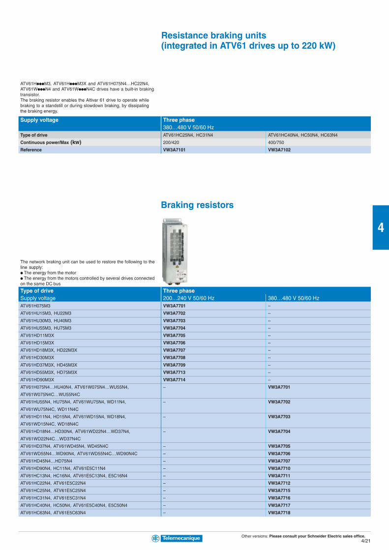
Other versions: Please consult your Schneider Electric sales office.4/21
4
Supply voltage Three phase380…480 V 50/60 Hz
Type of drive ATV61HC25N4, HC31N4 ATV61HC40N4, HC50N4, HC63N4
Continuous power/Max (kw) 200/420 400/750
Reference VW3A7101 VW3A7102
Braking resistors
Type of drive Three phaseSupply voltage 200…240 V 50/60 Hz 380…480 V 50/60 HzATV61H075M3 VW3A7701 –
ATV61HU15M3, HU22M3 VW3A7702 –
ATV61HU30M3, HU40M3 VW3A7703 –
ATV61HU55M3, HU75M3 VW3A7704 –
ATV61HD11M3X VW3A7705 –
ATV61HD15M3X VW3A7706 –
ATV61HD18M3X, HD22M3X VW3A7707 –
ATV61HD30M3X VW3A7708 –
ATV61HD37M3X, HD45M3X VW3A7709 –
ATV61HD55M3X, HD75M3X VW3A7713 –
ATV61HD90M3X VW3A7714 –
ATV61H075N4…HU40N4, ATV61W075N4…WU55N4, – VW3A7701
ATV61W075N4C…WU55N4C
ATV61HU55N4, HU75N4, ATV61WU75N4, WD11N4, – VW3A7702
ATV61WU75N4C, WD11N4C
ATV61HD11N4, HD15N4, ATV61WD15N4, WD18N4, – VW3A7703
ATV61WD15N4C, WD18N4C
ATV61HD18N4…HD30N4, ATV61WD22N4…WD37N4, – VW3A7704
ATV61WD22N4C…WD37N4C
ATV61HD37N4, ATV61WD45N4, WD45N4C – VW3A7705
ATV61WD55N4…WD90N4, ATV61WD55N4C…WD90N4C – VW3A7706
ATV61HD45N4…HD75N4 – VW3A7707
ATV61HD90N4, HC11N4, ATV61E5C11N4 – VW3A7710
ATV61HC13N4, HC16N4, ATV61E5C13N4, E5C16N4 – VW3A7711
ATV61HC22N4, ATV61E5C22N4 – VW3A7712
ATV61HC25N4, ATV61E5C25N4 – VW3A7715
ATV61HC31N4, ATV61E5C31N4 – VW3A7716
ATV61HC40N4, HC50N4, ATV61E5C40N4, E5C50N4 – VW3A7717
ATV61HC63N4, ATV61E5C63N4 – VW3A7718
Resistance braking units(integrated in ATV61 drives up to 220 kW)
ATV61HpppM3, ATV61HpppM3X and ATV61H075N4…HC22N4,ATV61WpppN4 and ATV61WpppN4C drives have a built-in brakingtransistor.The braking resistor enables the Altivar 61 drive to operate whilebraking to a standstill or during slowdown braking, by dissipatingthe braking energy.
The network braking unit can be used to restore the following to theline supply:p The energy from the motorp The energy from the motors controlled by several drives connectedon the same DC bus

Other versions: Please consult your Schneider Electric sales office.4/22
4
Complex, high-power machinesIP21 drives
Altivar 710.37…500 kW
Type of drive Single phase Three phase Three phase Three phase on base plateSupply voltage 200…240 V (3) 200…240 V (3) 380…480 V (3) 380…480 V (3)
Degree of protection IP21 for unprotected drives and IP41 on the upper part
Drive Output frequency 0.1…1600 Hz up to 37 kW, 0.1…500 Hz from 45 to 500 kW
Type of control Asynchronous motor Flux vector control with or without sensor, voltage/frequency ratio (2 or 5 points), ENA System
Synchronous motor Vector control without speed feedback
Transient overtorque 220% of nominal motor torque for 2 seconds, and 170% for 60 seconds
Speed range 1…1000 in closed loop mode with encoder feedback, 1…100 in open loop mode
Functions Number of functions > 150
Number of preset speeds 16
Number of I/O Analog inputs 2…4
Logic inputs 6…20
Analog outputs 1…3
Logic outputs 0…8
Relay outputs 2…4
Safety input 1
Dialogue Remote graphic display terminal or PowerSuite software workshop (see pages 4/25 and 4/30)
Communication Integrated Modbus and CANopen(see page 4/30) Available as an option Ethernet TCP/IP, Modbus/Uni-Telway, Fipio, Modbus Plus, Profibus DP, DeviceNet, INTERBUS
Cards (available as an option) Encoder interface cards, I/O extension cards, “Controller Inside” programmable card
Reduction of current harmonics DC choke integrated or supplied with the product, (optional chokes and passive filters, see page 4/26)
EMC Class A Integrated filter
Class B External filter available as an option
Motor power kW/HP 0.37/0.5 ATV71H075M3 S2 ATV71H037M3 S2 – –
0.75/1 ATV71HU15M3 S2 ATV71H075M3 S2 ATV71H075N4 (3) S2 ATV71P075N4Z S2
1.5/2 ATV71HU22M3 S3 ATV71HU15M3 S2 ATV71HU15N4 (3) S2 ATV71PU15N4Z S2
2.2/3 ATV71HU30M3 S3 ATV71HU22M3 S3 ATV71HU22N4 (3) S2 ATV71PU22N4Z S2
3/– ATV71HU40M3 (1) S3 ATV71HU30M3 S3 ATV71HU30N4 (3) S3 ATV71PU30N4Z S3
4/5 ATV71HU55M3 (1) S4 ATV71HU40M3 S3 ATV71HU40N4 (3) S3 ATV71PU40N4Z S3
5.5/7.5 ATV71HU75M3 (1) S5A ATV71HU55M3 S4 ATV71HU55N4 (3) S4 ATV71PU55N4Z S4
7.5/10 – ATV71HU75M3 S5A ATV71HU75N4 (3) S4 ATV71PU75N4Z S4
11/15 – ATV71HD11M3X (2) S5B ATV71HD11N4 (3) S5A –
15/20 – ATV71HD15M3X (2) S5B ATV71HD15N4 (3) S5B –
18.5/25 – ATV71HD18M3X (2) S6 ATV71HD18N4 (3) S5B –
22/30 – ATV71HD22M3X (2) S6 ATV71HD22N4 (3) S6 –
30/40 – ATV71HD30M3X (2) S7B ATV71HD30N4 (3) S7A –
37/50 – ATV71HD37M3X (2) S7B ATV71HD37N4 (3) S7A –
45/60 – ATV71HD45M3X (2) S7B ATV71HD45N4 (3) S8 –
55/75 – ATV71HD55M3X (2) S9 ATV71HD55N4 (3) S8 –
75/100 – ATV71HD75M3X (2) S10 ATV71HD75N4 (3) S8 –
90/125 – – ATV71HD90N4 S9 –
110/150 – – ATV71HC11N4 S10 –
132/200 – – ATV71HC13N4 S11 –
160/250 – – ATV71HC16N4 S12 –
200/300 – – ATV71HC20N4 S13 –
220/350 – – ATV71HC25N4 S13 –
280/450 – – ATV71HC28N4 S13 –
315/500 – – ATV71HC31N4 S14 –
355/– – – ATV71HC40N4 S14 –
500/700 – – ATV71HC50N4 S15 –
(1) Must be used with a line choke, see page 4/26
(2) Drive supplied without EMC filter
(3) To order a reinforced version of the drive for specific environmental conditions, conforming to IEC 60721-3-3 class 3c2, add S337 at the end of the reference.
E.g. ATV71H075N4S337
Dimensions (in mm) width x height x depth
S2 : 130 x 230 x 175 S3 : 155 x 260 x 187
S4 : 175 x 295 x 187 S5A : 210 x 295 x 213
S5B : 230 x 400 x 213 S6 : 240 x 420 x 236
S7A : 240 x 550 x 266 S7B : 320 x 550 x 266
S8 : 320 x 630 x 290 S9 : 320 x 920 x 377
S10 : 360 x 1022 x 377 S11 : 340 x 1190 x 377
S12 : 440 x 1190 x 377 S13 : 595 x 1190 x 377
S14 : 890 x 1390 x 377 S15 : 1120 x 1390 x 377

Other versions: Please consult your Schneider Electric sales office.4/23
4
IP54 drives
Type of drive Three phase Three phase range in ready-assembled enclosure (4)
380…480 V (3) 380…480 VDegree of protection UL Type 12/IP54 IP54 enclosure
Drive Output frequency 0.1…1600 Hz up to 37 kW, 0.1…500 Hz from 45 to 500 kW
Type of control Asynchronous motor Flux vector control with or without sensor, voltage/frequency ratio (2 or 5 points), ENA System
Synchronous motor Vector control without speed feedback
Transient overtorque 220% of nominal motor torque for 2 seconds, and 170% for 60 seconds
Speed range 1…1000 in closed loop mode with encoder feedback, 1…100 in open loop mode
Functions Number of functions > 150
Number of preset speeds 16
Number of I/O Analog inputs 2…4
Logic inputs 6…20
Analog outputs 1…3
Logic outputs 0…8
Relay outputs 2…4
Safety input 1
Dialogue Remote graphic display terminal or PowerSuite software workshop (see page 4/30)
Communication Integrated Modbus and CANopen(see page 4/30) Available as an option Ethernet TCP/IP, Modbus/Uni-Telway, Fipio, Modbus Plus, Profibus DP, DeviceNet, INTERBUS
Cards (available as an option) Encoder interface cards, I/O extension cards, “Controller Inside” programmable card
Reduction of current harmonics Optional chokes and passive filters (see page 4/26)
EMC Class A Integrated filter
Class B External filter available as an option
Motor power kW/HP 0.75/1 ATV71W075N4 S2 –
1.5/2 ATV71WU15N4 S2 –
2.2/3 ATV71WU22N4 S2 –
3/– ATV71WU30N4 S3 –
4/5 ATV71WU40N4 S3 –
5.5/7.5 ATV71WU55N4 S4 –
7.5/10 ATV71WU75N4 S4 –
11/15 ATV71WD11N4 S5A –
15/20 ATV71WD15N4 S5B –
18.5/25 ATV71WD18N4 S5B –
22/30 ATV71WD22N4 S6 –
30/40 ATV71WD30N4 S7A –
37/50 ATV71WD37N4 S7A –
45/60 ATV71WD45N4 S8 –
55/75 ATV71WD55N4 S8 –
75/100 ATV71WD75N4 S8 –
90/125 – ATV71HD90N4 ATV71E5D90N4 A1
110/150 – ATV71HC11N4 ATV71E5C11N4 A1
132/200 – ATV71HC13N4 ATV71E5C13N4 A1
160/250 – ATV71HC16N4 ATV71E5C16N4 A1
200/300 – ATV71HC20N4 ATV71E5C20N4 A2
220/350 – ATV71HC25N4 ATV71E5C25N4 A2
280/450 – ATV71HC28N4 ATV71E5C28N4 A2
200/300 – ATV71HC20N4 ATV71E5C20N4F A2
220/350 – ATV71HC25N4 ATV71E5C25N4F A2
280/450 – ATV71HC28N4 ATV71E5C28N4F A2
315/500 – ATV71HC31N4 ATV71E5C31N4 A3
400/600 – ATV71HC40N4 ATV71E5C40N4 A3
500/700 – ATV71HC50N4 ATV71E5C50N4 A4
(4) The Altivar 71 range in ready-assembled enclosure consists of:
– An ATV71H… drive
– A switch and fast-acting fuses
– An IP65 remote mounting kit for graphic display terminal
Dimensions (in mm) width x height x depth
ATV61W… ATV61E5C… in enclosure
SA2 : 235 x 490 x 272 A1 : 616 x 2000 x 600
SA3 : 235 x 490 x 286 A2 : 816 x 2000 x 600
SB : 255 x 525 x 286 A3 : 1016 x 2000 x 600
SC : 290 x 560 x 315 A3 : 1220 x 2000 x 600
SD : 310 x 665 x 315 A3 : 2024 x 2000 x 600
SE : 284 x 720 x 315 A4 : 1216 x 2000 x 600
SF : 284 x 880 x 343 A4 : 1820 x 2000 x 600
SG : 362 x 1000 x 364 A4 : 2224 x 2000 x 600
Ready-assembled enclosure with
braking transistor integrated in the
drive
Ready-assembled enclosure with
braking unit in the enclosure
Ready-assembled enclosure without
braking unit
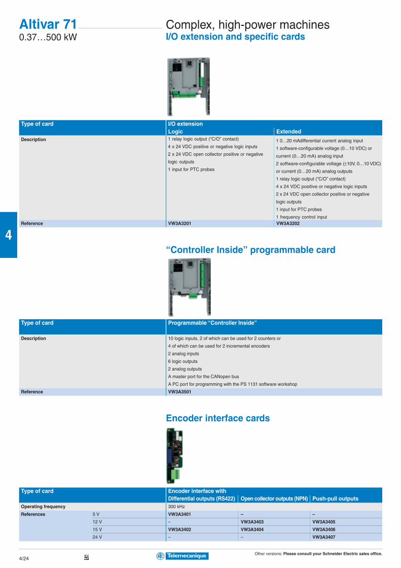
Other versions: Please consult your Schneider Electric sales office.4/24
4
1 relay logic output (“C/O” contact)
4 x 24 VDC positive or negative logic inputs
2 x 24 VDC open collector positive or negative
logic outputs
1 input for PTC probes
1 0…20 mAdifferential current analog input
1 software-configurable voltage (0…10 VDC) or
current (0…20 mA) analog input
2 software-configurable voltage (±10V, 0…10 VDC)
or current (0…20 mA) analog outputs
1 relay logic output (“C/O” contact)
4 x 24 VDC positive or negative logic inputs
2 x 24 VDC open collector positive or negative
logic outputs
1 input for PTC probes
1 frequency control input
Altivar 710.37…500 kW
Complex, high-power machinesI/O extension and specific cards
Type of card I/O extensionLogic Extended
Description
Reference VW3A3201 VW3A3202
“Controller Inside” programmable card
Type of card Programmable “Controller Inside”
Description 10 logic inputs, 2 of which can be used for 2 counters or
4 of which can be used for 2 incremental encoders
2 analog inputs
6 logic outputs
2 analog outputs
A master port for the CANopen bus
A PC port for programming with the PS 1131 software workshop
Reference VW3A3501
Encoder interface cards
Type of card Encoder interface withDifferential outputs (RS422) Open collector outputs (NPN) Push-pull outputs
Operating frequency 300 kHz
References 5 V VW3A3401 – –
12 V – VW3A3403 VW3A3405
15 V VW3A3402 VW3A3404 VW3A3406
24 V – – VW3A3407
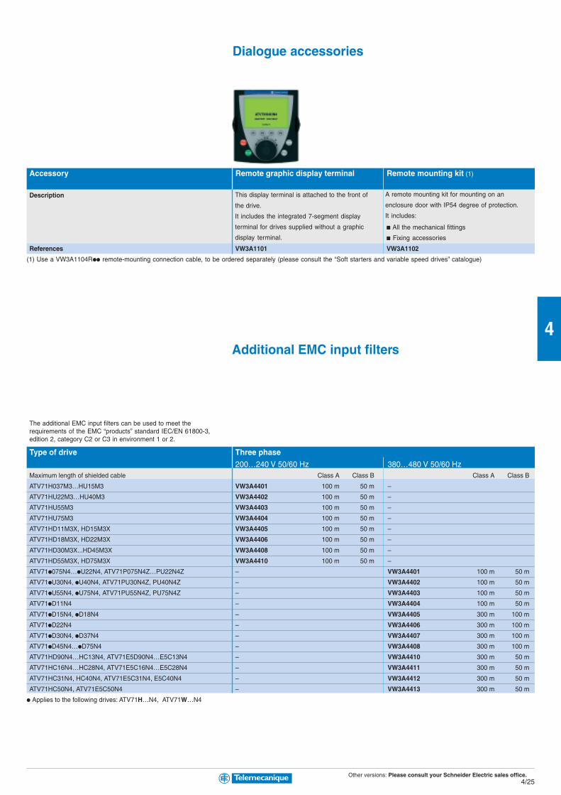
Other versions: Please consult your Schneider Electric sales office.4/25
4
Dialogue accessories
Accessory Remote graphic display terminal Remote mounting kit (1)
Description
b All the mechanical fittings
b Fixing accessories
References VW3A1101 VW3A1102
(1) Use a VW3A1104Rpp remote-mounting connection cable, to be ordered separately (please consult the “Soft starters and variable speed drives” catalogue)
Additional EMC input filters
Type of drive Three phase
200…240 V 50/60 Hz 380…480 V 50/60 HzMaximum length of shielded cable Class A Class B Class A Class B
ATV71H037M3…HU15M3 VW3A4401 100 m 50 m –
ATV71HU22M3…HU40M3 VW3A4402 100 m 50 m –
ATV71HU55M3 VW3A4403 100 m 50 m –
ATV71HU75M3 VW3A4404 100 m 50 m –
ATV71HD11M3X, HD15M3X VW3A4405 100 m 50 m –
ATV71HD18M3X, HD22M3X VW3A4406 100 m 50 m –
ATV71HD30M3X...HD45M3X VW3A4408 100 m 50 m –
ATV71HD55M3X, HD75M3X VW3A4410 100 m 50 m –
ATV71p075N4…pU22N4, ATV71P075N4Z…PU22N4Z – VW3A4401 100 m 50 m
ATV71pU30N4, pU40N4, ATV71PU30N4Z, PU40N4Z – VW3A4402 100 m 50 m
ATV71pU55N4, pU75N4, ATV71PU55N4Z, PU75N4Z – VW3A4403 100 m 50 m
ATV71pD11N4 – VW3A4404 100 m 50 m
ATV71pD15N4, pD18N4 – VW3A4405 300 m 100 m
ATV71pD22N4 – VW3A4406 300 m 100 m
ATV71pD30N4, pD37N4 – VW3A4407 300 m 100 m
ATV71pD45N4…pD75N4 – VW3A4408 300 m 100 m
ATV71HD90N4…HC13N4, ATV71E5D90N4…E5C13N4 – VW3A4410 300 m 50 m
ATV71HC16N4…HC28N4, ATV71E5C16N4…E5C28N4 – VW3A4411 300 m 50 m
ATV71HC31N4, HC40N4, ATV71E5C31N4, E5C40N4 – VW3A4412 300 m 50 m
ATV71HC50N4, ATV71E5C50N4 – VW3A4413 300 m 50 m
p Applies to the following drives: ATV71H…N4, ATV71W…N4
The additional EMC input filters can be used to meet therequirements of the EMC “products” standard IEC/EN 61800-3,edition 2, category C2 or C3 in environment 1 or 2.
This display terminal is attached to the front of
the drive.
It includes the integrated 7-segment display
terminal for drives supplied without a graphic
display terminal.
A remote mounting kit for mounting on an
enclosure door with IP54 degree of protection.
It includes:

Other versions: Please consult your Schneider Electric sales office.4/26
4
Altivar 710.37…500 kW
Type of drive Three phaseSupply voltage 200…240 V 50/60 Hz 380…480 V 50/60 HzATV71H037M3...H075M3 VW3A4551 –
ATV71HU15M3...HU22M3 VW3A4552 –
ATV71HU30M3 VW3A4553 –
ATV71HU40M3 VW3A4554 –
ATV71HU75M3, HD11M3X VW3A4555 –
ATV71HD15M3X VW3A4556 –
ATV71HD18M3X…HD45M3X VW3A4557 –
ATV71HD55M3X VW3A4562 –
ATV71HD75M3X VW3A4563 –
ATV71p075N4, pU15N4, ATV71P075N4Z, PU15N4Z – VW3A4551
ATV71pU22N4…pU40N4, ATV71PU22N4Z…PU40N4Z – VW3A4552
ATV71pU55N4, pU75N4, ATV71PU55N4Z, PU75N4Z – VW3A4553
ATV71pD11N4, pD15N4 – VW3A4554
ATV71pD18N4, pD22N4 – VW3A4555
ATV71pD30N4…pD55N4 – VW3A4556
ATV71pD75N4 – VW3A4557
ATV71HD90N4, ATV71E5D90N4 – VW3A4558
ATV71HC11N4, ATV71E5C11N4 – VW3A4559
ATV71HC13N4, ATV71E5C13N4 – VW3A4560
ATV71HC16N4, ATV71E5C16N4 – VW3A4561
ATV71HC20N4, ATV71E5C20N4 – VW3A4562
ATV71HC25N4, ATV71E5C25N4 Motor P 220 kW – VW3A4562
Motor P 250 kW – VW3A4563
ATV71HC28N4, HC31N4, ATV71E5C28N4, E5C31N4 – VW3A4564
ATV71HC40N4, ATV71E5C40N4 Motor P 355 kW – VW3A4565
Motor P 400 kW – VW3A4566
ATV71HC50N4, ATV71E5C50N4 – VW3A4567
p Applies to the following drives: ATV71H…N4, ATV71W…N4
Reduction of current harmonicsOptional DC chokes (1)
Type of drive Three phaseSupply voltage 200…240 V 50/60 Hz 380…480 V 50/60 HzATV71H037M3 VW3A4501 –
ATV71H075M3 VW3A4503 –
ATV71HU15M3 VW3A4505 –
ATV71HU22M3 VW3A4506 –
ATV71HU30M3 VW3A4507 –
ATV71HU40M3, HU55M3 VW3A4508 –
ATV71HU75M3 VW3A4509 –
ATV71HD11M3X, HD15M3X VW3A4510 –
ATV71HD18M3X, HD22M3X VW3A4511 –
ATV71HD30M3X… HD45M3X VW3A4512 –
ATV71p075N4, ATV71P075N4Z – VW3A4501
ATV71pU15N4, ATV71PU15N4Z – VW3A4502
ATV71pU22N4, pU30N4, ATV71PU22N4Z,, PU30N4Z – VW3A4503
ATV71pU40N4 , ATV71PU40N4Z – VW3A4504
ATV71pU55N4, ATV71PU55N4Z – VW3A4505
ATV71pU75N4, ATV71PU75N4Z – VW3A4506
ATV71pD11N4 – VW3A4507
ATV71pD15N4, pD18N4 – VW3A4508
ATV71pD22N4…pD37N4 – VW3A4510
ATV71pD45N4…pD75N4 – VW3A4511
(1) For ATV 71HD55M3X, HD75M3X and ATV 71HD90N4… HC50N4 drives, the choke is supplied as standard with the drive.
Complex, high-power machinesReduction of current harmonicsAC line chokes
A line choke can be used to provide improved protection againstovervoltages on the line supply and to reduce harmonic distortionof the current produced by the drive.
DC chokes are used to reduce current harmonics in order tocomply with standard 61000-3-2 for drives in which the line currentis more than 16 A and less than 75 A.

Other versions: Please consult your Schneider Electric sales office.4/27
4
Type of drive Three phase 400 V 50/60 Hz Three phase 460 V 50/60 HzTHDI 16% (1) THDI 10% (2) THDI 16% (1) THDI 10% (2)
ATV71p075N4…pU30N4, ATV71P075N4Z…PU30N4Z VW3A4601 VW3A4621 VW3A4 641 VW3A4 661
ATV71pU40N4,pU55N4, ATV71PU40N4Z, PU55N4Z VW3A4602 VW3A4622 VW3A4 642 VW3A4 662
ATV71pU75N4,pD11N4, ATV71PU75N4Z VW3A4603 VW3A4623 VW3A4 643 VW3A4 663
ATV71pD15N4 VW3A4604 VW3A4624 VW3A4 644 VW3A4 664
ATV71pD18N4, pD22N4 VW3A4606 VW3A4626 VW3A4 645 VW3A4 665
ATV71pD30N4 VW3A4607 VW3A4627 VW3A4 646 VW3A4 666
ATV71pD37N4 VW3A4607 VW3A4627 VW3A4 647 VW3A4 667
ATV71pD45N4 VW3A4608 VW3A4628 VW3A4 647 VW3A4 668
ATV71pD55N4 VW3A4608 VW3A4628 VW3A4 648 VW3A4 668
ATV71pD75N4 VW3A4609 VW3A4629 VW3A4 648 VW3A4 668
ATV71HD90N4, ATV71E5D90N4 VW3A4609 VW3A4629 VW3A4 649 VW3A4 669
ATV71HC11N4, ATV71E5C11N4 VW3A4610 VW3A4630 VW3A4 649 VW3A4 669
ATV71HC13N4, ATV71E5C13N4 VW3A4611 VW3A4631 VW3A4 656 VW3A4 676
ATV71HC16N4, ATV71E5C16N4 VW3A4612 VW3A4632 VW3A4 650 VW3A4 670
ATV71HC20N4, HC25N4, ATV71E5C20N4, E5C25N4 VW3A4613 VW3A4633 VW3A4 651 VW3A4 671
ATV71HC25N4, ATV71E5C25N4 VW3A4611 VW3A4631 VW3A4 656 VW3A4 676
ATV71HC28N4, HC31N4, HC40N4, ATV71E5C28N4, E5C31N4, E5C40N4 VW3A4612 VW3A4632 VW3A4 650 VW3A4 670
ATV71HC40N4, ATV71E5C40N4 VW3A4619 VW3A4639 VW3A4 657 VW3A4 677
ATV71HC50N4, ATV71E5C50N4 VW3A4612 VW3A4632 VW3A4 651 VW3A4 671
p Applies to the following drives: ATV71H…N4, ATV71W…N4
(1) By adding a DC choke, we get: THD ≤ 10%
(2) By adding a DC choke, we get: THD ≤ 15%
These reduced current harmonics are obtained on condition that the THDu is < 20% and the RSCE > 66%.
Sinusoidal filters
Type of drive Three phaseSupply voltage 200…240 V 50/60 Hz 380…480 V 50/60 HzATV71H037M3...HU15M3 (2) VW3A5201 –
ATV71HU22M3, HU30M3 VW3A5202 –
ATV71HU40M3... HU75M3 VW3A5203 –
ATV71HD11M3X, HD15M3X VW3A5204 –
ATV71HD18M3X, HD22M3X VW3A5205 –
ATV71HD30M3X... HD45M3X VW3A5206 –
ATV71HD55M3X, HD75M3X VW3A5208 –
ATV71p075N4...pU40N4, ATV71P075N4Z…PU40N4Z (2) – VW3A5201
ATV71pU55N4, ATV71PU55N4Z – VW3A5202
ATV71pU75N4...pD15N4, ATV71PU75N4Z – VW3A5203
ATV71pD18N4...pD30N4 – VW3A5204
ATV71pD37N4, pD45N4 – VW3A5205
ATV71pD55N4, pD75N4 – VW3A5206
ATV71 HD90N4, HC11N4, ATV71E5D90N4, E5C11N4 – VW3A5207
ATV71 HC13N4, HC16N4, ATV71E5C13N4, E5C16N4 – VW3A5208
ATV71 HC20N4, ATV71E5C20N4 – VW3A5209
ATV71 HC25N4, ATV71E5C25N4 Motor P 220 kW – VW3A5209
Motor P 250 kW – VW3A5210
ATV71 HC28N4, HC31N4, ATV71E5C28N4, E5C31N4 – VW3A5210
ATV71 HC40N4, ATV71E5C40N4 Motor P 355 kW – VW3A5210
Motor P 400 kW – VW3A5211
ATV71 HC50N4, ATV71E5C50N4 – VW3A5211
p Applies to the following drives: ATV71H…N4, ATV71W…N4
(2) For these drive references, it is advisable to use a lower category motor with a sinusoidal filter
Passive filters
Sinusoidal filters allow Altivar 71 drives to operate with longer motorcables (up to 1000 m).
A passive filter is used to reduce current harmonics with totalharmonic distortion factors of less than 16% or 10%. These factorsmay be less than 10% or 5% if used with a DC choke.

Other versions: Please consult your Schneider Electric sales office.4/28
4
Type of drive Max. motor cable length Three phaseShielded Unshielded 200…240 V 50/60 Hz 380…480 V 50/60 Hz
ATV71H037M3…HU22M3 150 m 300 m VW3A5101 –
ATV71HU30M3…HU75M3 200 m 260 m VW3A5102 –
300 m 300 m VW3A5103 –
ATV71HD11M3X…HD22M3X 150 m 300 m VW3A5103 –
ATV71HD30M3X… HD45M3X 150 m 300 m VW3A5 04 –
ATV71HD55M3X, HD75M3X 150 m 300 m VW3A5105 –
ATV71p075N4…pU40N4, ATV71P075N4Z…PU40N4Z 75 m 90 m – VW3A5101
85 m 95 m – VW3A5102
160 m 200 m – VW3A5103
ATV71pU55N4…pD18N4, ATV71PU55N4Z…PU75N4Z 85 m 95 m – VW3A5102
160 m 200 m – VW3A5103
200 m 300 m – VW3A5104
ATV71pD22N4…pD30N4 140 m 170 m – VW3A5103
150 m 300 m – VW3A5104 (1)
ATV71pD37N4 97 m 166 m – VW3A5103
200 m 300 m – VW3A5104 (1)
ATV71Hp45N4…pD75N4 150 m 300 m – VW3A5104 (1)
ATV71HD90N4, ATV71E5D90N4 200 m 300 m – VW3A5104 (1)
ATV71HC11N4, HC13N4, ATV71E5C11N4, E5C13N4 150 m 250 m – VW3A5105 (1)
ATV71HC16N4…HC20N4, ATV71E5C16N4…E5C20N4 250 m 300 m – VW3A5106 (1)
ATV71HC25N4, ATV71E5C25N4 Motor P 220 kW 250 m 300 m – VW3A5106 (1)
Motor P 250 kW 200 m 250 m – VW3A5107 (1)
ATV71HC28N4, HC31N4, ATV71E5C28N4, E5C31N4 200 m 250 m – VW3A5107 (1)
ATV71HC40N4, ATV71E5C40N4 Motor P 355 kW 200 m 250 m – VW3A5107 (1)
Motor P 400 kW 250 m 300 m – VW3A5108 (1)
ATV71HC50N4, ATV71E5C50N4 250 m 300 m – VW3A5108 (1)
p Applies to the following drives: ATV71H…N4, ATV71W…N4
(1) 3 single phase chokes are included with the drive
Complex, high-power machinesOutput filter optionsMotor chokes
Altivar 710.37…500 kW
Above a certain motor cable length, it is advisable to insert a motorchoke between the drive and the motor. This maximum length dependson the drive rating and the type of motor cable.

Other versions: Please consult your Schneider Electric sales office.4/29
4
Supply voltage Three phase380…480 V
Type of drive ATV71HC20N4…HC28N4 ATV71HC31N4…HC50N4
Continuous power/Max (kw) 200/420 400/750
Reference VW3A7101 VW3A7102
Braking resistorsType of drive Braking resistor 40 s cycle Hoisting resistor 40 s cycleSupply voltage 200…240 V 50/60 Hz 380…480 V 50/60 Hz 200…240 V 50/60 Hz 380…480 V 50/60 HzATV71H037M3, H075M3 VW3A7701 – VW3A7801 –
TV71HU15M3, HU22M3 VW3A7702 – VW3A7802 –
ATV71HU30M3, HU40M3 VW3A7703 – VW3A7803 –
ATV71HU55M3, HU75M3 VW3A7704 – VW3A7804 –
ATV71HD11M3X VW3A7705 – VW3A7805 –
ATV71HD15M3X VW3A7706 – VW3A7806 –
ATV71HD18M3X, HD22M3X VW3A7707 – VW3A7807 –
ATV71HD30M3X VW3A7708 – VW3A7808 –
ATV71HD37M3X, HD45M3X VW3A7709 – VW3A7809 –
ATV71HD55M3X VW3A7713 – VW3A7810 –
ATV71HD75M3X VW3A7714 – – –
ATV71p075N4…pU40N4, ATV71P075N4Z…PU40N4Z – VW3A7701 – VW3A7801
ATV71pU55N4, pU75N4, ATV71PU55N4Z, PU75N4Z – VW3A7702 – VW3A7802
ATV71pD11N4, pD15N4 – VW3A7703 – VW3A7803
ATV71pD18N4…pD30N4 – VW3A7704 – VW3A7804
ATV71pD37N4 – VW3A7705 – VW3A7805
ATV71pD45N4…pD75N4 – VW3A7707 – VW3A7806
ATV71HD90N4, ATV71E5D90N4 – VW3A7710 – VW3A7811
ATV71HC11N4, HC13N4, ATV71E5C11N4, E5C13N4 – VW3A7711 – VW3A7812
ATV71HC16N4, ATV71E5C16N4 – VW3A7712 – VW3A7813
ATV71HC20N4, ATV71E5C20N4 – VW3A7715 – VW3A7814
ATV71HC25N4, HC28N4, ATV71E5C25N4, E5C28N4 – VW3A7716 – VW3A7815
ATV71HC31N4, HC40N4, ATV71E5C31N4, E5C40N4 – VW3A7717 – VW3A7816
ATV71HC50N4, ATV71E5C50N4 – VW3A7718 – VW3A7817
p Applies to the following drives: ATV71H…N4, ATV71W…N4
Network braking unitsLine voltage 400 VAC 460 VAC
Braking power 7 VW3A7201 –
continuous (kw) 13 VW3A7202 –
11 VW3A7203 –
– – VW3A7231
21,5 VW3A7204 VW3A7232
26 VW3A7205 VW3A7233
32 VW3A7206 VW3A7234
38 VW3A7207/VW3A7208 VW3A7235/VW3A7236/VW3A7237/VW3A7238
86 VW3A7209 VW3A7239
120 VW3A7210 VW3A7240
135 VW3A7211 –
200 VW3A7212 –
240 – VW3A7241
Resistance braking units(integrated in ATV71 drives up to 160 kW)
ATV 71HpppM3, ATV71HpppM3X and ATV71H075N4…HC16N4drives have a built-in braking transistor.The braking resistor enables the Altivar 71 drive to operate whilebraking to a standstill or during slowdown braking, by dissipatingthe braking energy.
The network braking unit can be used to restore the following to theline supply:– The energy from the motor– The energy from the motors controlled by several drivesconnected on the same DC bus.
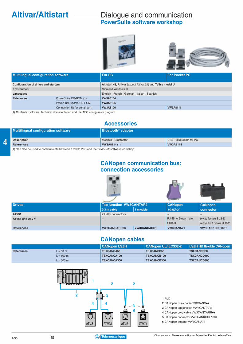
Other versions: Please consult your Schneider Electric sales office.4/30
4
1
3
2
44 56
2
2
ATV31 ATV31 ATV61 ATV71
Altivar/Altistart Dialogue and communicationPowerSuite software workshop
Multilingual configuration software For PC For Pocket PC
Configuration of drives and starters Altistart 48, Altivar (except Altivar 21) and TeSys model U
Environment Microsoft Windows ®
Languages English - French - German - Italian - Spanish
References PowerSuite CD-ROM (1) VW3A8104
PowerSuite update CD-ROM VW3A8105
Connection kit for serial port VW3A8106 VW3A8111
(1) Contents: Software, technical documentation and the ABC configurator program
AccessoriesMultilingual configuration software Bluetooth® adaptor
Description Modbus - Bluetooth® USB - Bluetooth® for PC
References VW3A8114 (1) VW3A8115
(1) Can also be used to communicate between a Twido PLC and the TwidoSoft software workshop
CANopen communication bus:connection accessories
Drives Tap junction VW3CANTAP20.3 m cable 1 m cable
ATV31 2 RJ45 connectors – –
ATV61 and ATV71 –
References VW3CANCARR03 VW3CANCARR1 VW3CANA71 VW3CANKCDF180T
CANopen cablesCANopen LSZH CANopen UL/IEC332-2 LSZH HD flexible CANopen
References L = 50 m TSXCANCA50 TSXCANCB50 TSXCANCD50
L = 100 m TSXCANCA100 TSXCANCB100 TSXCANCD100
L = 300 m TSXCANCA300 TSXCANCB300 TSXCANCD300
1 PLC
2 CANopen trunk cable TSXCANCpp
3 CANopen tap junction VW3CANTAP2
4 CANopen drop cable VW3CANCARRpp
5 CANopen connector VW3CANKCDF180T
6 CANopen adaptor VW3CANA71
RJ 45 to 9-way male
SUB-D
9-way female SUB-D
output for 2 cables at 180°
CANopenadaptor
CANopenconnector

Other versions: Please consult your Schneider Electric sales office.4/31
4
544 7
1
2 43 46 6 5
ATV61 ATV71 ATV21 ATS48 ATV31
Modbus communication bus:connection accessories
Starters/drives Splitter box Subscriber Line terminatorsAltistart 48, Altivar 21, 31, 61, 71 socketDescription 10 connectors 3 screw terminals 2 SUB-D connectors For connector For screw terminals
RJ45 and line terminator 15-way female and RJ 45 R = 120 Ω, C = 1 nF
1 screw terminal RC and 2 screw R = 120 Ω, C = 1 nF
terminals RC line
terminator
References LU9GC3 TSXSCA50 TSXSCA62 VW3A8306RC VW3A8306DRC
Modbus connectionStarters/drives Cables Double shielded twisted pair cables T-junction boxesAltistart 48, Altivar 21, 31, 61, 71 RS 485Description 2 connectors 1 connector Supplied without With integrated cable
RJ 45 RJ45 and one stripped connector
end
References L = 0.3 m VW3A8306R03 – – VW3A8306TF03
L = 1 m VW3A8306R10 – – VW3A8306TF10
L = 3 m VW3A8306R30 VW3A8306D30 – –
L = 100 m – – TSXCSA100 –
L = 200 m – – TSXCSA200 –
L = 500 m – – TSXCSA500 –
Connection via splitter boxes
and RJ 45 connectors
1 PLC
2 Modbus cable depending on the type of PLC
3 Modbus splitter box LU9GC3
4 Modbus drop cables VW3A8306Rpp
5 Line terminators VW3A8306RC
6 Modbus T-junction boxes VW3A8306TFpp (with cable)
7 Modbus drop cable VW3A58306Rpp
Tap junction
tap junction
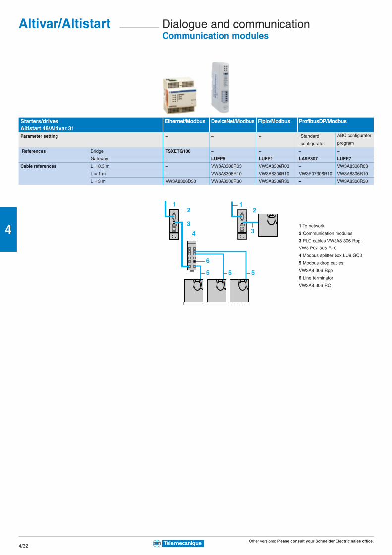
Other versions: Please consult your Schneider Electric sales office.4/32
4
21
6
55 5
3
4
21
3
Dialogue and communicationCommunication modules
Altivar/Altistart
Starters/drives Ethernet/Modbus DeviceNet/Modbus Fipio/Modbus ProfibusDP/ModbusAltistart 48/Altivar 31Parameter setting – – –
References Bridge TSXETG100 – – – –
Gateway – LUFP9 LUFP1 LA9P307 LUFP7
Cable references L = 0.3 m – VW3A8306R03 VW3A8306R03 – VW3A8306R03
L = 1 m – VW3A8306R10 VW3A8306R10 VW3P07306R10 VW3A8306R10
L = 3 m VW3A8306D30 VW3A8306R30 VW3A8306R30 – VW3A8306R30
1 To network
2 Communication modules
3 PLC cables VW3A8 306 Rpp,
VW3 P07 306 R10
4 Modbus splitter box LU9 GC3
5 Modbus drop cables
VW3A8 306 Rpp
6 Line terminator
VW3A8 306 RC
Standard
configurator
ABC configurator
program
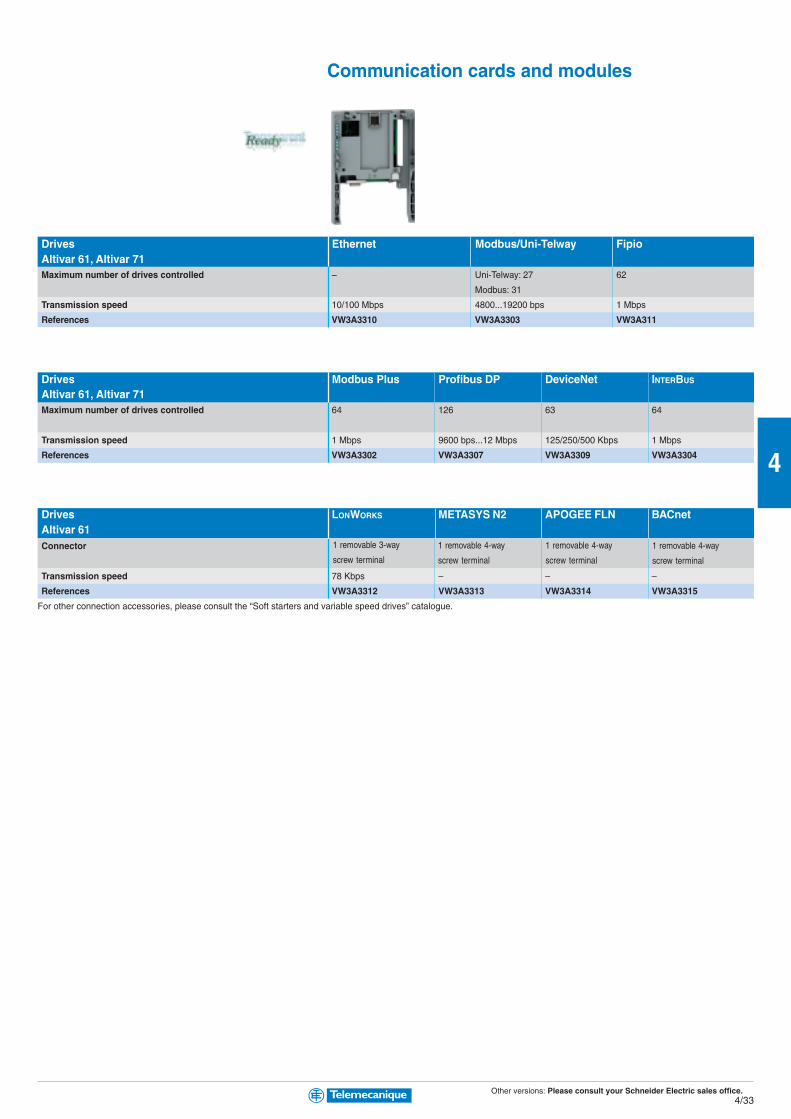
Other versions: Please consult your Schneider Electric sales office.4/33
4
Communication cards and modules
Drives Ethernet Modbus/Uni-Telway FipioAltivar 61, Altivar 71Maximum number of drives controlled – Uni-Telway: 27 62
Modbus: 31
Transmission speed 10/100 Mbps 4800...19200 bps 1 Mbps
References VW3A3310 VW3A3303 VW3A311
Drives Modbus Plus Profibus DP DeviceNet INTERBUS
Altivar 61, Altivar 71Maximum number of drives controlled 64 126 63 64
Transmission speed 1 Mbps 9600 bps...12 Mbps 125/250/500 Kbps 1 Mbps
References VW3A3302 VW3A3307 VW3A3309 VW3A3304
Drives LONWORKS METASYS N2 APOGEE FLN BACnetAltivar 61Connector
Transmission speed 78 Kbps – – –
References VW3A3312 VW3A3313 VW3A3314 VW3A3315
For other connection accessories, please consult the “Soft starters and variable speed drives” catalogue.
1 removable 4-way
screw terminal
1 removable 4-way
screw terminal
1 removable 4-way
screw terminal
1 removable 3-way
screw terminal

Other versions: please consult your Schneider Electric agency.4/34
4
Motion controlModules for Modicon Premium platform
Module type For translators For analog control servomotors(amplifier for stepper motor) (for asynchronous and brushless motors)
Control outputs RS 422 +/- 10 V
Compatible with drives Lexium 05 Lexium 05/17D
Functions Linear axes – Limited Limited or infinite Limited or
infinite (1)
Slave axes – With static ratio With dynamic ratio –
Frequency for each axis 187 kHz 500 kHz with incremental encoder, 200 kHz with absolute encoder
(SSI serial or parallel output)
Number of axes 1 2 2 4 2 4 3
Reference TSXCFY11 TSXCFY21 TSXCAY21 TSXCAY41 TSXCAY22 TSXCAY42 TSXCAY33
(1) With linear interpolation on 2 or 3 axes
Module type Servomotors with SERCOS® digital ring(for brushless motors)
Control outputs SERCOS® network ring
Compatible with ranges Lexium 17D
Functions Linear or infinite independent axes, slave axes with cam profile or ratio
Processing 4 sets of axes with linear 4 sets of axes with linear and circular 4 sets of axes with linear
interpolation from 2 to 8 axes interpolation from 2 to 3 axes (2) interpolation from 2 to 8 axes
Frequency for each axis 4 Mb SERCOS® network ring
Number of axes 8 (3) 8 (3) 16 (4)
Reference TSXCSY84 TSXCSY85 TSXCSY164
(2) TSXCSY85 module supplied with TJE trajectory editor: linear trajectories with links between segments according to polynomial or circular interpolation and circular trajectories.
(3) 8 real axes, 4 imaginary axes and 4 remote axes
(4) 16 axes (real axes, imaginary and remote axes)
Connection accessories for Modicon Premiumand Quantum modules
Type Fiber optic cablesFor Lexium 17D MDHA1…N00/A00 drives
Connection Pre-equipped cable with SMA connectors
Reference L = 0.3 m 990MCO00001
L = 0.9 m 990MCO00003
L = 1.5 m 990MCO00005
L = 4.5 m 990MCO00015
L = 16.5 m 990MCO00055
L = 22.5 m 990MCO00075
L = 37.5 m 990MCO00125
Lexium

Other versions: please consult your Schneider Electric agency.4/35
4
Motion controlModules for Modicon Quantum platform
Module type For analog control servomotorsSingle axis
Control outputs RS 422
Compatible with drives Lexium 17D
Functions Master/slave position capture
Synchronization of a master/slave, torque control
Frequency for each axis 200 kHz nominal, 500 kHz max. with incremental encoder
Number of axes 1 real axis, 1 remote axis
Reference 140MSB10100
Module type Servomotors with SERCOS® digital ring (for brushless motors)
Control outputs SERCOS® network ring
Compatible with ranges Lexium 17D
Functions Linear or infinite independent axes, slave axes with cam profile or ratio
Processing 4 sets of axes with linear interpolation from 2 to 8 axes
Frequency for each axis 4 Mb SERCOS® network ring
Number of axes With MMF Start programming kit (1)
Reference 140MMS42501 (2) 140MMS53502 (3)
(1) 8 real axes, 4 imaginary axes, 4 remote axes, 4 coordinate sets, 4 follower sets, cam profiles
(2) Maximum 22 axes including 16 real axes with assistance from our application services
(3) Maximum 32 axes including 22 real axes with assistance from our application services

Other versions: please consult your Schneider Electric agency.4/36
4
Motion controlServo drives for BSH servo motors
Servo drive type Digital for servo motorsSize 1 Size 2 Size 3
Supply voltage 110…120 VAC single phase
Output current Continuous (RMS) 4 A 8 A 15 A
Maximum (Peak) 10 A 17 A 28 A
Safety function Integrated “Power Removal”
Braking resistor Integrated
EMC filter Integrated
Reference with Integrated CANopen (1) LXM05AD10F1 LXM05AD17F1 LXM05AD28F1
Servo drive type Digital for servo motorsSize 1 Size 2 Size 3 Size 1 Size 2 Size 3
Supply voltage 200…240 VAC single phase 200…240 VAC 3-phase
Output current Continuous (RMS) 4 A 8 A 15 A 4 A 8 A 17 A
Maximum (Peak) 10 A 17 A 28 A 10 A 17 A 42 A
Safety function Integrated “Power Removal”
Braking resistor Integrated
EMC filter Integrated Not integrated
Reference with Integrated CANopen (1) LXM05AD10M2 LXM05AD17M2 LXM05AD28M2 LXM05AD10M3X LXM05AD17M3X LXM05AD42M3X
Servo drive type Digital for servo motorsSize 2 Size 2 Size 3 Size 4
Supply voltage 380…480 VAC 3-phase 380…480 VAC 3-phase
Output current Continuous (RMS) 6 A 9A 15 A 25 A
Maximum (Peak) 14 A 22 A 34 A 57 A
Safety function Integrated “Power Removal”
Braking resistor Integrated
EMC filter Integrated
Reference with Integrated CANopen (1) LXM05AD14N4 LXM05AD22N4 LXM05AD34N4 LXM05AD57N4
(1) To order a Lexium 05 servo drive with PROFIBUS DP bus, remplace “A” in the reference by “B”. Exemple LXM05AD14N4 become LXM05BD14N4.
Lexium 05
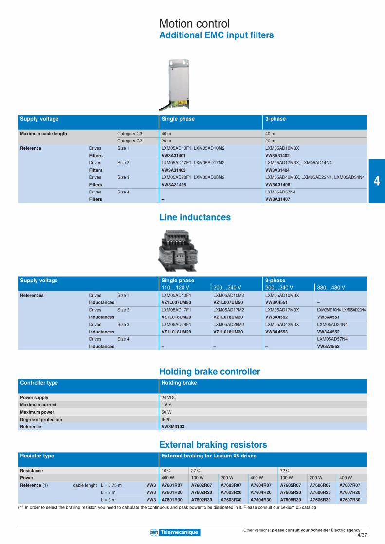
Other versions: please consult your Schneider Electric agency.4/37
4
Motion controlAdditional EMC input filters
Supply voltage Single phase 3-phase
Maximum cable length Category C3 40 m 40 m
Category C2 20 m 20 m
Reference Drives Size 1 LXM05AD10F1, LXM05AD10M2 LXM05AD10M3X
Filters VW3A31401 VW3A31402
Drives Size 2 LXM05AD17F1, LXM05AD17M2 LXM05AD17M3X, LXM05AD14N4
Filters VW3A31403 VW3A31404
Drives Size 3 LXM05AD28F1, LXM05AD28M2 LXM05AD42M3X, LXM05AD22N4, LXM05AD34N4
Filters VW3A31405 VW3A31406
Drives Size 4 LXM05AD57N4
Filters – VW3A31407
Line inductances
Supply voltage Single phase 3-phase110…120 V 200…240 V 200…240 V 380…480 V
References Drives Size 1 LXM05AD10F1 LXM05AD10M2 LXM05AD10M3X
Inductances VZ1L007UM50 VZ1L007UM50 VW3A4551 –
Drives Size 2 LXM05AD17F1 LXM05AD17M2 LXM05AD17M3X LXM05AD10N4, LXM05AD22N4
Inductances VZ1L018UM20 VZ1L018UM20 VW3A4552 VW3A4551
Drives Size 3 LXM05AD28F1 LXM05AD28M2 LXM05AD42M3X LXM05AD34N4
Inductances VZ1L018UM20 VZ1L018UM20 VW3A4553 VW3A4552
Drives Size 4 LXM05AD57N4
Inductances – – – VW3A4552
Holding brake controllerController type Holding brake
Power supply 24 VDC
Maximum current 1.6 A
Maximum power 50 W
Degree of protection IP20
Reference VW3M3103
External braking resistorsResistor type External braking for Lexium 05 drives
Resistance 10 Ω 27 Ω 72 ΩPower 400 W 100 W 200 W 400 W 100 W 200 W 400 W
Reference (1) cable lenght L = 0.75 m VW3 A7601R07 A7602R07 A7603R07 A7604R07 A7605R07 A7606R07 A7607R07
L = 2 m VW3 A7601R20 A7602R20 A7603R20 A7604R20 A7605R20 A7606R20 A7607R20
L = 3 m VW3 A7601R30 A7602R30 A7603R30 A7604R30 A7605R30 A7606R30 A7607R30
(1) In order to select the braking resistor, you need to calculate the continuous and peak power to be dissipated in it. Please consult our Lexium 05 catalog

Other versions: please consult your Schneider Electric agency.4/38
4
2
1
Twido
4
3
1
2 2
Twido
Multilingual configuration software For PC
Configuration of drives and softstarters Lexium 05 / Altivar / Altistart
Environment Microsoft Windows ®
Languages English - French - German - Italian - Spanish
Reference PowerSuite CD-ROM (1)
Connection kit VW3A8106
(1) A dedicated PowerSuite software for Lexium is delivred with each servo drive.
CANopen communication bus connection
Connection type Via spring terminal (CN1)Connector IP20 Cable
Connector type Bended at 90° SUB-D –
Type of cable – Halogen free UL certification For heavy duty
References TSXCANKCDF90 – – –
L = 50 m – TSXCANCA50 TSXCANCB50 TSXCANCD50
L = 100 m – TSXCANCA100 TSXCANCB100 TSXCANCD100
L = 300 m – TSXCANCA300 TSXCANCB300 TSXCANCD300
Connection type Via RJ45 connectorJunction box Cable
Description 2 RJ45 ports 2 RJ45 connectors
References VW3CANTAP2 –
L = 0.3 m – VW3CANCARR03
L = 100 m – VW3CANCARR1
Motion controlPowerSuite software workshop
Lexium 05
Launch 1st quarter 2006
1 SUB-D connector
2 CANopen cable standard
3 Junction box
4 Cable for CANopen bus
1 SUB-D connector
2 CANopen cable standard

Other versions: please consult your Schneider Electric agency.4/39
4
544
1
2 43 46 6 532
6 7
45
1
Drives Lexium 05
Connection type Description Splitter box with Junction box Subscriber socket
10 RJ45 connectors for drop cable for drop cable
and 1 screw terminal block VW3A8306D30 VW3A8306
Reference LU9GC3 TSXSCA50 TSXSCA62
Line terminators For RJ 45 connector R = 120 Ω, C = 1 nf R = 150 Ω, C = 1 nf
Reference VW3A8306RC VW3A8306R
For screw terminals R = 120 Ω, C = 1 nf R = 150 Ω, C = 1 nf
Reference VW3A8306DRC VW3A8306DR
T-junction boxes With integrated cable 0.3 m VW3A8306TF03
With integrated cable 1 m VW3A8306TF10
Cables Description 2 RJ 45 connectors
Reference 0.3 m VW3A8306R03
1 m VW3A8306R10
3 m VW3A8306R30
RS 485 shielded twisted Description 1 RJ45 connector and one stripped end
double pair cables Reference 3 m VW3A8306D30
Description Supplied without connector
Reference 100 m TSXCSA100
200 m TSXCSA200
500 m TSXCSA500
Connection with RJ45 splitter box and screw terminals Connection with junction box or subscriber sockets
Motion controlModbus serial linkconnection accessories
1 Controller Twido
2 Cable for controller Twido serial link
3 Modbus splitter box LU9 GC3
4 Modbus drop cables VW3 A8 306Rpp
5 Line terminators VW3 A8 306RC
6 Modbus T-junction boxes VW3 A8 306TFpp (with cable)
1 Controller Twido
2 Cable for controller Twido serial link
3 Modbus cables TSX CSAp00
4 T-junction box TSX SCA 50
5 Subscriber socket TSX SCA 62
6 Modbus drop cables VW3 A8 306
7 Modbus drop cables VW3 A8 306 D30
Connection via screw terminals
In this case, a Modbus drop cable (VW3 A8 306D30) and line terminators (VW3 A8 306DRC) are used.

Other versions: please consult your Schneider Electric agency.4/40
4
Motion controlBSH servo motors for Lexium 05
Lexium 05
BSH servo motors Lexium 05 servo drives110/120 V single phase, 200/240 V single phase,
with integrated EMC filter with integrated EMC filter
LXM 05p LXM 05p
Reference Torque at Nominale D10F1 D17F1 D28F1 Nominale D10M2 D17M2 D28M2
standstill speed 0.4 kW 0.65 kW 1.4 kW speed 0.75 kW 1.2 kW 2.5 kW
BSH 0551T 0.5 Nm 3000 min-1 1.4 Nm 6000 min-1 1.4 Nm
BSH 0552M 0.9 Nm 1500 min-1 2.2 Nm
BSH 0552P 0.9 Nm 4000 min-1 2.7 Nm
BSH 0552T 0.9 Nm 3000 min-1 1.8 Nm 2.7 Nm 6000 min-1 1.8 Nm
BSH 0553M 1.3 Nm 1500 min-1 3.5 Nm
BSH 0553P 1.3 Nm 4000 min-1 3.2 Nm
BSH 0553T 1.3 Nm 3000 min-1 3.3 Nm 6000 min-1 3.3 Nm
BSH 0701P 1.4 Nm 3000 min-1 2.6 Nm
BSH 0701T 1.4 Nm 3000 min-1 2.4 Nm 6000 min-1 3.2 Nm
BSH 0702M 2.1 Nm 1500 min-1 5.6 Nm
BSH 0702P 2.1 Nm 3000 min-1 4.6 Nm 5.6 Nm
BSH 0702T 2.1 Nm 3000 min-1 4.1 Nm 6000 min-1 4.1 Nm 6.7 Nm
BSH 0703M 2.8 Nm 1500 min-1 8.5 Nm
BSH 0703P 2.8 Nm 3000 min-1 7.2 Nm 10.3 Nm
BSH 0703T 2.8 Nm 3000 min-1 7.4 Nm 6000 min-1 7.4 Nm
BSH 1001T 3.4 Nm 2500 min-1 8.5 Nm 6000 min-1 8.5 Nm
BSH 1002P 5.5 Nm 2000 min-1 16 Nm
BSH 1003P 7.8 Nm 2000 min-1 19.7 Nm
200/240 V three phase, 380/480 V three phase,
without integrated EMC filter with integrated EMC filter
LXM 05p LXM 05p
Reference Torque at Nominale D10M3X D17M3X D42M3X Nominale D14N4 D22N4 D34N4 D57N4
standstill speed 0.75 kW 1.4 kW 3.2 kW speed 1.4 kW 2 kW 3 kW 6 kW
BSH 0551T 0.5 Nm 6000 min-1 1.4 Nm
BSH 0552M 0.9 Nm 1500 min-1 2.2 Nm
BSH 0552P 0.9 Nm 4000 min-1 2.7 Nm 6000 min-1 2.7 Nm
BSH 0552T 0.9 Nm 6000 min-1 1.8 Nm
BSH 0553M 1.3 Nm 1500 min-1 3.5 Nm
BSH 0553P 1.3 Nm 4000 min-1 3.2 Nm 6000 min-1 3.9 Nm
BSH 0553T 1.3 Nm 6000 min-1 3.3 Nm
BSH 0701M 1.4 Nm 1500 min-1 2.6 Nm
BSH 0701P 1.4 Nm 3000 min-1 2.6 Nm
BSH 0701T 1.4 Nm 6000 min-1 2.4 Nm 3.2 Nm
BSH 0702M 2.1 Nm 1500 min-1 5.6 Nm
BSH 0702P 2.1 Nm 3000 min-1 4.6 Nm 5.6 Nm 6000 min-1 5.6 Nm
BSH 0702T 2.1 Nm 6000 min-1 6.7 Nm
BSH 0703M 2.8 Nm 1500 min-1 8.5 Nm 3000 min-1 8.5 Nm
BSH 0703P 2.8 Nm 3000 min-1 7.2 Nm 6000 min-1 8.7 Nm
BSH 0703T 2.8 Nm 6000 min-1 10.2 Nm
BSH 1001M 3.4 Nm 2000 min-1 7.1 Nm
BSH 1001P 3.4 Nm 2000 min-1 7.1 Nm 4000 min-1 8.5 Nm
BSH 1001T 3.4 Nm 4000 min-1 8.5 Nm
BSH 1002M 5.5 Nm 2000 min-1 13.3 Nm
BSH 1002P 5.5 Nm 2000 min-1 11.2 Nm 4000 min-1 13.9 Nm
BSH 1002T 5.5 Nm 4000 min-1 16 Nm
BSH 1003M 7.8 Nm 2000 min-1 23 Nm
BSH 1003P 7.8 Nm 2000 min-1 23 Nm 4000 min-1 23 Nm
BSH 1004P 9.3 Nm 2000 min-1 35.7 Nm 3000 min-1 23.4 Nm 35.7 Nm
BSH 1401P 11.4 Nm 2500 min-1 28 Nm
BSH 1401T 11.4 Nm 3000 min-1 27.1 Nm
BSH 1402M 19.2 Nm 1250 min-1 57 Nm
BSH 1402P 19.2 Nm 1500 min-1 45.4 Nm 2500 min-1 38.6 Nm 54.3 Nm
BSH 1402T 19.2 Nm 3000 min-1 29.6 Nm
BSH 1403M 25.4 Nm 1250 min-1 70.3 Nm 84.3 Nm
BSH 1403P 25.4 Nm 3000 min-1 62.2 Nm
BSH 1404M 32.1 Nm 1500 min-1 102 Nm
BSH 1404P 32.1 Nm 3000 min-1 63.8 Nm
BSH 2051M 36 Nm 1500 min-1 82 Nm
Availability of BSH 055 and BSH 205 servomotors: 1st quarter 2006.p replaced by A for the CANopen/analog inputs version, replaced by B for the Profibus DP version.
This value
corresponds to the peak torque
at standstill that can be provided
by the Lexium 05 servo drive/
BSH servo motor combination.
1.4 Nm

Other versions: please consult your Schneider Electric agency.4/41
4
Motion controlBSH servo motors for Lexium 05
To order a BSH motor, please use these references
Reference to be completed : BSH ppppppppppppppp ppppp ppppp ppppp ppppp ppppp ppppp AFlange size 55 mm 055
70 mm 070
100 mm 100
140 mm 140
205 mm 205
Length (Number of magnet stacks) 1 1
2 2
3 3
4 4
Winding type Lowest speed M
Medium speed P
Highest speed T
Shaft (1) w/o key (smooth) : IP40 (IP65) 0
with key : IP40 (IP65) 1
w/o key : IP65 2
with key IP65 3
Encoder Absolute SinCos, single turn (128 periods per revolution) 1
Absolute SinCos multi turn (4096 revolutions) 2
Brake w/o brake A
with brake F
Connection System Straight connector 1
right angle turnable connector 2
Mounting International standard mounting A
(1) Other possibilities to be detailed: see www.telemecanique.com
Connecting cables
Cable type Power cable Encoder cableEquiped with 1 connector (motor side) Equiped with 2 connectors
Servo motor type BSH… 055pp / 070pp / 100pp / 1401T / 1402T / 2051M All type
1401P /1402M / 1402P / 1403P / 1404P
1403M / 1404M
Servo drive type LXM05… All type D42M3X / D57N4 D57N4 All type
Composition 4x1.5 mm2 + 2x1 mm2 4x2.5 mm2 + 2x1 mm2 4x4 mm2 + 2x1 mm2 5x(2x2.5 mm2) + 2x0.5 mm2
Reference L = 3 m VW3M5101R30 VW3M5102R30 VW3M5103R30 VW3M8101R30
L = 5 m VW3M5101R50 VW3M5102R50 VW3M5103R50 VW3M8101R50
L = 10 m VW3M5101R100 VW3M5102R100 VW3M5103R100 VW3M8101R100
L = 15 m VW3M5101R150 VW3M5102R150 VW3M5103R150 VW3M8101R150
L = 20 m (2) VW3M5101R200 VW3M5102R200 VW3M5103R200 VW3M8101R200
(2) For cable lengths of > 20 m, see www.telemecanique.com.

Other versions: please consult your Schneider Electric agency.4/42
4
Drive type Digital for SER and BPH/BPL brushless motorsLexium 17D
Supply voltage 208…480 VAC 3-phase 50/60 Hz (230 VAC single phase authorized with derating)
Output current Continuous 1.5 A 3 A 6 A 10 A 20 A
Maximum (discontinuous, 5 s) 3 A 6 A 10 A 20 A 40 A
Anti-start With or without
Braking resistor Integrated
EMC filter Integrated
Reference (1) MDHA1004ppppp00 MDHA1008ppppp00 MDHA1017ppppp00 MDHA1028ppppp00 MDHA1056ppppp00
(1) For a drive without anti-start function, replace the p at the end of the reference with N, or for one with integrated anti-start function, with A
Drive type Digital for BPH brushless motorsLexium 17D HP
Supply voltage 208…480 VAC 3-phase
Output current Continuous 40 A 70 A
Maximum (discontinuous, 5 s) 80 A 140 A
Anti-start Integrated
Braking resistor Not integrated
EMC filter Not integrated
Reference MDHA1112A00 MDHA1198A00
Control and connectivity of Lexium 17D drives
Drive connectivity Connectivity type
Integrated +/- 10 V, Pulse/direction, CANopen Reference
Via an optional card (1 slot available) High-speed SERCOS® digital ring AM0SER001V000
Fipio fieldbus AM0FIP001V000
Modbus Plus network AM0MBP001V000
Profibus DP fieldbus AM0PBS001V000
CANopen machine bus (standard medium) AM02CA001V000
Card with 14 I/8O for controlling the integrated position indexer AM0INE001V000
Motion controlDrives for SER and BPH/BPL brushless motors
Lexium 17D
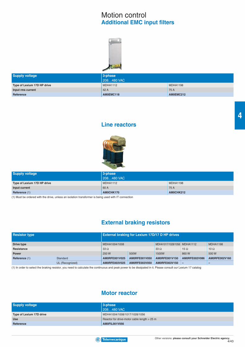
Other versions: please consult your Schneider Electric agency.4/43
4
Supply voltage 3-phase208…480 VAC
Type of Lexium 17D HP drive MDHA1112 MDHA1198
Input rms current 42 A 75 A
Reference AM0EMC118 AM0EMC212
Line reactors
Supply voltage 3-phase208…480 VAC
Type of Lexium 17D HP drive MDHA1112 MDHA1198
Input current 60 A 75 A
Reference (1) AM0CHK170 AM0CHK212
(1) Must be ordered with the drive, unless an isolation transformer is being used with IT connection
External braking resistors
Resistor type External braking for Lexium 17D/17 D HP drives
Drive type MDHA1004/1008 MDHA1017/1028/1056 MDHA1112 MDHA1198
Resistance 33 Ω 33 Ω 15 Ω 10 ΩPower 250 W 500W 1500W 860 W 500 W
Reference (1) Standard AM0RFE001V025 AM0RFE001V050 AM0RFE001V150 AM0RFE002V086 AM0RFE002V160
UL (Recognized) AM0RFE003V025 AM0RFE003V050 AM0RFE003V150 – –
(1) In order to select the braking resistor, you need to calculate the continuous and peak power to be dissipated in it. Please consult our Lexium 17 catalog
Motor reactor
Supply voltage 3-phase208…480 VAC
Type of Lexium 17D drive MDHA1004/1008/1017/1028/1056
Use Reactor for drive-motor cable length > 25 m
Reference AM0FIL001V056
Motion controlAdditional EMC input filters

Other versions: please consult your Schneider Electric agency.4/44
4
Motion controlUnilink software for Lexium 17D drives
Lexium 17D
Unilink software is used to configure, set parameters and make adjustments on Lexium MHDA drives
according to the associated SER/BPH brushless motor and the requirements of the application. During
these debugging phases,
the PC-compatible terminal, supporting the Unilink software in Windows 95/98, 2000, NT 4.0 or XP, is
connected to the MHDA drives via a serial link (9-way SUB-D connector marked X6).
There are three possible configurable operating modes:
b +/- 10 V analog control mode controlled by Premium or Quantum motion
control module.
b Off line mode with integrated position indexer controlled by:
– 5 I/2 O integrated in the Lexium 17D drive (or by 14 I/8 O option card)
– CANopen, Fipio, Modbus Plus or Profibus DP bus
b SERCOS® mode, high-speed digital ring on optical fiber.
The initial screen providing access to the Unilink software services and functions is divided into
three zones:
1 Banner at the top of the screen for accessing the main functions.
2 Mimic diagram for accessing configuration/parameter setting and realtime display of the
various drive values.
3 Zone at the bottom of the screen indicating the drive status.
Configuration and adjustment software “Lexium motion tools” for PC
Drive configuration Lexium 17D
Environment Microsoft Windows ®
Language English, French, German, Italian and Spanish
Reference CD-ROM (1) AM0CSW001V350
(1) Contents: Unilink software + documentation
Accessories
Type of accessory Backup key
Use Saving and instant retrieval of drive parameters (without a PC)
Reference AM0PCM001V000

Other versions: please consult your Schneider Electric agency.4/45
4
Motion controlSER brushless motors for Lexium 17D
Motor type SER brushless type
Compatible Lexium 17 drive type MDHA1004ppppp00 MDHA1008ppppp00 MDHA1017ppppp00 MDHA1028ppppp00
Torque at standstill Mechanical
continuous/peak speed
Reference 1.1/2.5 Nm 6000 rpm SER39A4L7Sppppppppppppppppppppppppp
(1) 1.1/4 Nm 6000 rpm SER39A4L7Sppppppppppppppppppppppppp
2.2/2.4 Nm 6000 rpm SER39B4L3Sppppppppppppppppppppppppp
2.2/8 Nm 6000 rpm SER39B4L3Sppppppppppppppppppppppppp
2.9/4.7 Nm 6000 rpm SER39C4L3Sppppppppppppppppppppppppp
2.9/9.4 Nm 6000 rpm SER39C4L3Sppppppppppppppppppppppppp
4.2/8.2 Nm 5500 rpm SER3BA4L5Sppppppppppppppppppppppppp
4.5/15 Nm 5500 rpm SER3BA4L5Sppppppppppppppppppppppppp
4.6/9.2 Nm 6000 rpm SER3BA4L3Sppppppppppppppppppppppppp
4.6/15.3 Nm 6000 rpm SER3BA4L3Sppppppppppppppppppppppppp
6/12 Nm 6000 rpm SER3BB4L3Sppppppppppppppppppppppppp
6.6/20 Nm 6000 rpm SER3BB4L3Sppppppppppppppppppppppppp
6.6/15.8 Nm 5800 rpm SER3BB4L5Sppppppppppppppppppppppppp
6.6/25 Nm 5800 rpm SER3BB4L5Sppppppppppppppppppppppppp
8.3/16 Nm 2500 rpm SER3BC4L7Sppppppppppppppppppppppppp
8.6/17 Nm 4800 rpm SER3BC4L5Sppppppppppppppppppppppppp
10/28 Nm 4800 rpm SER3BC4L5Sppppppppppppppppppppppppp
10/32 Nm 2500 rpm SER3BC4L7Sppppppppppppppppppppppppp
13.4/24 Nm 2750 rpm SER3BD4L7Sppppppppppppppppppppppppp
13.4/29 Nm 5000 rpm SER3BD4L5Dppppppppppppppppppppppppp
13.4/38 Nm 2750 rpm SER3BD4L7Sppppppppppppppppppppppppp
(1) Complete the references using the table below
To order an SER motor, complete the above referencesReference to be completed: SER39/3B A/B/C/D 4L 3/5/7 S/D pppppppppp ppppp ppppp ppppp
Sensor integrated Resolver with 1 pair of poles RA
in the motor SinCos multi-turn absolute encoder MO
Shaft seal IP41 without holding brake A
with holding brake 1
IP56 without holding brake B
with holding brake 2
Without speed reduction gear O
Shaft extension Untapped 1
With speed reduction gear Type PLE80, PLE120, PLE160 (2)
Reduction ratio 3:1, 5:1, 8:1 (2)
(2) For an SER motor with speed reduction gear: see the “Lexium 17D motion control” catalog.
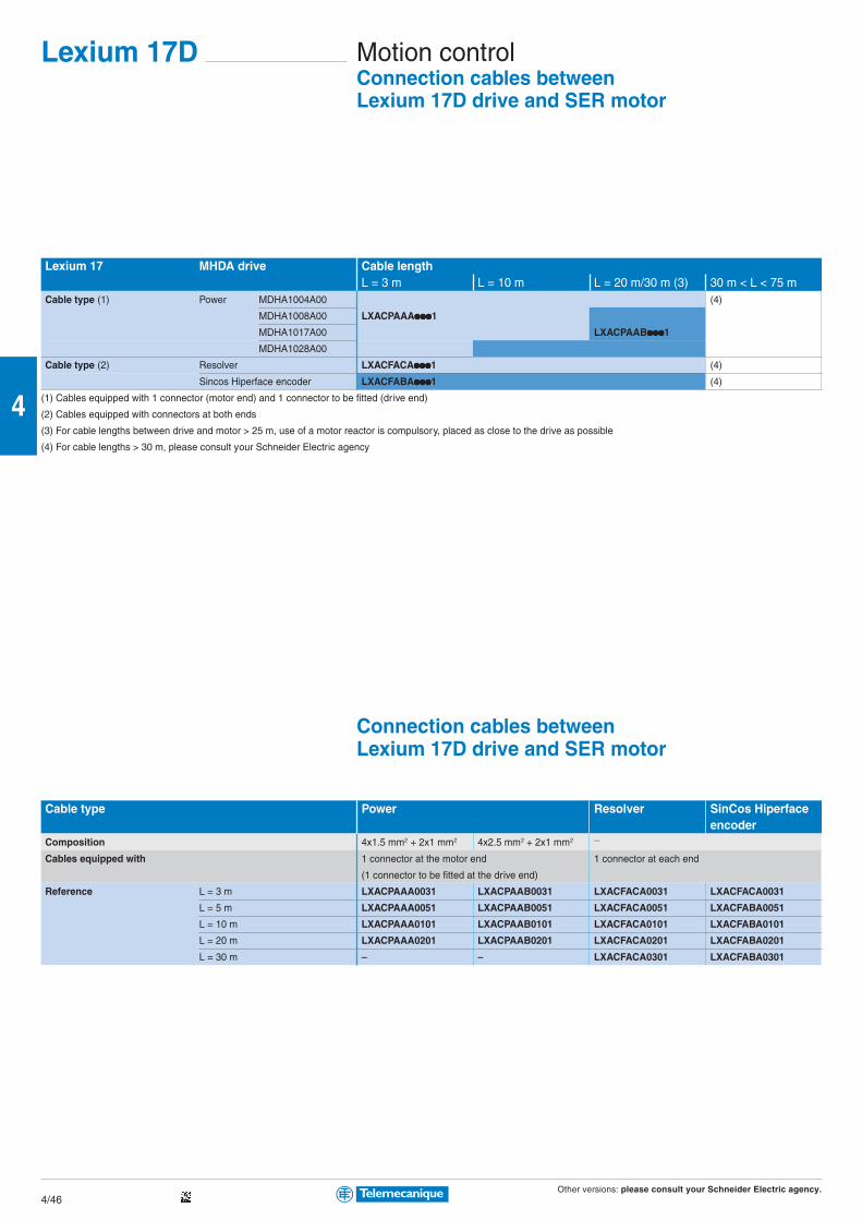
Other versions: please consult your Schneider Electric agency.4/46
4
Lexium 17 MHDA drive Cable lengthL = 3 m L = 10 m L = 20 m/30 m (3) 30 m < L < 75 m
Cable type (1) Power MDHA1004A00 (4)
MDHA1008A00 LXACPAAAppppppppppppppp1
MDHA1017A00 LXACPAABppppppppppppppp1
MDHA1028A00
Cable type (2) Resolver LXACFACAppppppppppppppp1 (4)
Sincos Hiperface encoder LXACFABAppppppppppppppp1 (4)
(1) Cables equipped with 1 connector (motor end) and 1 connector to be fitted (drive end)
(2) Cables equipped with connectors at both ends
(3) For cable lengths between drive and motor > 25 m, use of a motor reactor is compulsory, placed as close to the drive as possible
(4) For cable lengths > 30 m, please consult your Schneider Electric agency
Connection cables betweenLexium 17D drive and SER motor
Cable type Power Resolver SinCos Hiperfaceencoder
Composition 4x1.5 mm2 + 2x1 mm2 4x2.5 mm2 + 2x1 mm2 —
Cables equipped with 1 connector at the motor end 1 connector at each end
(1 connector to be fitted at the drive end)
Reference L = 3 m LXACPAAA0031 LXACPAAB0031 LXACFACA0031 LXACFACA0031
L = 5 m LXACPAAA0051 LXACPAAB0051 LXACFACA0051 LXACFABA0051
L = 10 m LXACPAAA0101 LXACPAAB0101 LXACFACA0101 LXACFABA0101
L = 20 m LXACPAAA0201 LXACPAAB0201 LXACFACA0201 LXACFABA0201
L = 30 m – – LXACFACA0301 LXACFABA0301
Motion controlConnection cables betweenLexium 17D drive and SER motor
Lexium 17D

Other versions: please consult your Schneider Electric agency.4/47
4
Motor type BPH brushless type
Compatible Lexium 17 drive type MDHA 1004A00 1008A00 1017A00 1028A00 1056A00 1112A 1198A
Torque at standstill Mechanical
continuous/peak speed
Reference (1) BPH
0.4/1.1 Nm 8000 rpm 0552S5pppppppppppppppppppp0ppppp
0.9/1.7 Nm 6000 rpm 0751N5ppppppppppppppppppppAppppp
1.3/3.4 Nm 6000 rpm 0751N5ppppppppppppppppppppAppppp
1.3/2.5 Nm 6000 rpm 0752N5ppppppppppppppppppppAppppp
2.3/4.8 Nm 6000 rpm 0752N5ppppppppppppppppppppAppppp
3.7/7.2 Nm 6000 rpm 0952N5ppppppppppppppppppppAppppp
4.3/13.4 Nm 6000 rpm 0952N5ppppppppppppppppppppAppppp
6/13.4 Nm 6000 rpm 0953N5ppppppppppppppppppppAppppp
6/20.3 Nm 6000 rpm 0953N5ppppppppppppppppppppAppppp
7.4/13.6 Nm 6000 rpm 1152N5ppppppppppppppppppppAppppp
7.4/19.3 Nm 6000 rpm 1152N5pppppppppppppppppppp0ppppp
6.8/13.5 Nm 6000 rpm 1153N5ppppppppppppppppppppAppppp
10.5/19.4 Nm 6000 rpm 1153N5ppppppppppppppppppppAppppp
11.4/18 Nm 4000 rpm 1442N5ppppppppppppppppppppAppppp
12/30 Nm 4000 rpm 1442N5ppppppppppppppppppppAppppp
14.5/24.2 Nm 4000 rpm 1423N5ppppppppppppppppppppAppppp 1423N5ppppppppppppppppppppAppppp
17/42 Nm 4000 rpm 1902N5ppppppppppppppppppppAppppp
25/37.5 Nm 4000 rpm 1903K5ppppppppppppppppppppAppppp
36/57 Nm 4000 rpm 1904K5ppppppppppppppppppppAppppp
46/76.2 Nm 4000 rpm 1907K5ppppppppppppppppppppAppppp
75/157 Nm 4000 rpm 1907K5ppppppppppppppppppppAppppp
90/163 Nm 4000 rpm 190AK5ppppppppppppppppppppAppppp
100/230 Nm 4000 rpm 0190AK5ppppppppppppppppppppAppppp
(1) Complete the references using the tables below
To order a BPH motor, complete the above referencesReference to be completed: BPH0552S5 ppppp pppppppppp ppppp 0 ppppp
Sensor integrated in the motor Resolver with 1 pair of poles U
Holding brake Without A2
With F2
Shaft extension Key C
Untapped L
Degree of protection IP65 (casing) IP54 (shaft extension) 0
To order a BPH motor, complete the above referencesReference to be completed: BPH0751N5….BPH190AK5 ppppp pppppppppp ppppp A ppppp
Sensor integrated in the motor Resolver with 1 pair of poles M
Multi-turn high-resolution absolute encoder, Sincos Hiperface (4096 revolutions) A
Single-turn high-resolution absolute encoder, Sincos Hiperface (4096 revolutions) B
Holding brake Without A2
With F2
Shaft extension Key C
Untapped L
Degree of protection IP65 (casing and shaft extension) 1
IP67 (casing and shaft extension) 2
Motion controlBPH brushless motors for Lexium 17D

Other versions: please consult your Schneider Electric agency.4/48
4
Motor type BPL brushless type
Compatible Lexium 17 drive type MDHA1008A00 MDHA101700
Torque at standstill Mechanical
continuous/peak speed
Reference (1) 1.1/2.4 Nm 6000 rpm BPL0751V5pppppA2pppppAppppp
1.7/3.5 Nm 6000 rpm BPL0951V5pppppA2pppppAppppp
2.8/7.3 Nm 6000 rpm BPL0753N5pppppA2pppppAppppp
2/5.5 Nm 6000 rpm BPL0951V5pppppA2pppppAppppp
5.4/13.4 Nm 6000 rpm BPL0953N5pppppA2pppppAppppp
(1) Complete the references using the tables below
To order a BPL motor, complete the above referencesReference to be completed: BPL0751V5...953N5 ppppp A2 ppppp A ppppp
Sensor integrated in the motor Resolver with 1 pair of poles M
Multi-turn high-resolution absolute encoder, Sincos Hiperface (4096 revolutions) A
Single-turn high-resolution absolute encoder, Sincos Hiperface B
Holding brake Without A2
Shaft extension Key C
Untapped L
Degree of protection IP65 1
(casing and shaft extension) IP67 2
Motion controlBPL compact brushless motors for Lexium 17D
Lexium 17D
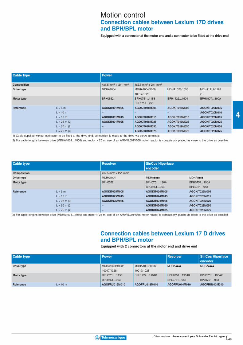
Other versions: please consult your Schneider Electric agency.4/49
4
Motion controlConnection cables between Lexium 17D drivesand BPH/BPL motorEquipped with a connector at the motor end and a connector to be fitted at the drive end
Cable type Power
Composition 4x1.5 mm2 + 2x1 mm2 4x2.5 mm2 + 2x1 mm2
Drive type MDHA1004 MDHA1004/1008/ MDHA1028/1056 MDHA1112/1198
10017/1028 (1)
Motor type BPH0552 BPH0751...1153 BPH1422…1904 BPH1907…190A
BPL0751…953
Reference L = 5 m AGOKIT001M005 AGOKIT018M005 AGOKIT019M005 AGOKIT020M005
L = 10 m – – – AGOKIT020M010
L = 15 m AGOKIT001M015 AGOKIT018M015 AGOKIT019M015 AGOKIT020M015
L = 25 m (2) AGOKIT001M025 AGOKIT018M025 AGOKIT019M025 AGOKIT020M025
L = 50 m (2) – AGOKIT018M050 AGOKIT019M050 AGOKIT020M050
L = 75 m (2) – AGOKIT018M075 AGOKIT019M075 AGOKIT020M075
(1) Cable supplied without connector to be fitted at the drive end, connection is made to the drive via screw terminals
(2) For cable lengths between drive (MDHA1004…1056) and motor > 25 m, use of an AM0FIL001V056 motor reactor is compulsor y, placed as close to the drive as possible
Cable type Resolver SinCos Hiperfaceencoder
Composition 4x2.5 mm2 + 2x1 mm2
Drive type MDHA1004 MDHApppp MDHApppp
Motor type BPH0552 BPH0751...190A BPH0751...190A
BPL0751…953 BPL0751…953
Reference L = 5 m AGOKIT025M005 AGOKIT024M005 AGOKIT023M005
L = 15 m AGOKIT025M015 AGOKIT024M015 AGOKIT023M015
L = 25 m (2) AGOKIT025M025 AGOKIT024M025 AGOKIT023M025
L = 50 m (2) – AGOKIT024M050 AGOKIT023M050
L = 75 m (2) – AGOKIT024M075 AGOKIT023M075
(2) For cable lengths between drive (MDHA1004…1056) and motor > 25 m, use of an AM0FIL001V056 motor reactor is compulsor y, placed as close to the drive as possible
Connection cables between Lexium 17 D drivesand BPH/BPL motor
Cable type Power Resolver SinCos Hiperfaceencoder
Drive type MDHA1004/1008/ MDHA1004/1008/ MDHApppp MDHApppp
10017/1028 10017/1028
Motor type BPH0751...1153 BPH1422…1904K BPH0751…190AK BPH0751…190AK
BPL0751…953 BPL0751…953 BPL0751…953
Reference L = 10 m AGOFRU015M010 AGOFRU016M010 AGOFRU014M010 AGOFRU013M010
Equipped with 2 connectors at the motor end and drive end

Pow
er c
ontr
ol a
nd p
rote
ctio
n
The essentialguideA simplifiedselection guideenabling you toquickly selectmotor starters.
For a new start!
Accurate and reliable controlof motors
TeSys
TeSys range provide you more simplicity, compactness,openness and flexibility... so many evolutions and new items to aid your productivity.
New horizons are opening up to you. Increase your productivity -adopt our solutions which help to simplify setting-up.
A rangeof simple,compact andadvancedcomponentsfor power controland protection.
Motor starters
b Ready-to-use component combinations,designed to work together in perfect harmony.
b Safe operation and level of coordinationguaranteed by a major manufacturer.
Power circuit control
b A wide range of components.
b Solutions for a variety of power controlapplications: lighting, capacitor switching,heating, changeover contactor pairs, resistiveloads, upstream protection.
5/0
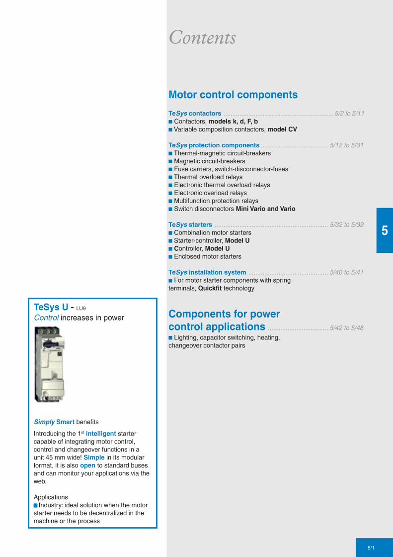
TeSys U - LU9
Control increases in power
Simply Smart benefits
Introducing the 1st intelligent startercapable of integrating motor control,control and changeover functions in aunit 45 mm wide! Simple in its modularformat, it is also open to standard busesand can monitor your applications via theweb.
Applicationsbbbbb Industry: ideal solution when the motorstarter needs to be decentralized in themachine or the process
5/1
5
Contents
Motor control components
TeSys contactors .............................................................. 5/2 to 5/11b Contactors, models k, d, F, bb Variable composition contactors, model CV
TeSys protection components ...................................... 5/12 to 5/31b Thermal-magnetic circuit-breakersb Magnetic circuit-breakersb Fuse carriers, switch-disconnector-fusesb Thermal overload relaysb Electronic thermal overload relaysb Electronic overload relaysb Multifunction protection relaysb Switch disconnectors Mini Vario and Vario
TeSys starters ................................................................ 5/32 to 5/39b Combination motor startersb Starter-controller, Model Ub Controller, Model Ub Enclosed motor starters
TeSys installation system ............................................. 5/40 to 5/41b For motor starter components with springterminals, Quickfit technology
Components for powercontrol applications .................................. 5/42 to 5/48b Lighting, capacitor switching, heating,changeover contactor pairs

Other versions: please consult your Schneider Electric agency.5/2
5
Connections screw clamp terminals
Rated operational current Ie max AC-3 (Ue ≤ 440V) 6 A 9 A 12 A
Ie AC-1 (θ ≤ 40° C) - 20 A -
Rated operational power 220/240 V 1.5 kW 2.2 kW 3 kW
in category AC3 380/400 V…415/440 V 2.2 kW 4 kW 5.5 kW
660/690 V…500 V 3 kW 4 kW 4 kW
Contactor type (1)* c LC1-K06•• LC1-K09•• LC1-K12••
a LP1-K06•• or LP4-K06•• LP1-K09 or LP4-K09•• LP1-K12 or LP4-K12••
Reversing contactor type * c LC2-K06 LC2-K09 LC2-K12
with mechanical interlock a LP2-K06 or LP5-K06 LP2-K09 or LP5-K09 LP2-K12 or LP5-K12
spring terminals
Add the figure 3 before the voltage code. Example LC1-K0610•• becomes LC1-K06103••
Faston connectors, 1 x 6.35 or 2 x 2.8
Add the figure 7 before the voltage code. Example LC1-K0610•• becomes LC1-K06107••
solder pins for printed circuit boards
Add the figure 5 before the voltage code. Example LC1-K0610•• becomes LC1-K06105••
(1) Basic reference, to be completed by adding 01 for N/C auxiliary contact, or 10 for N/O auxiliary contact.
* Basic reference to be completed by adding the coil voltage
Standard control circuit voltagesc c c c c supply
Contactors LC1-K (0.8…1.15 Uc) (0.85…1.1UC)
Volts 12 20 24 36 42 48 110 115 120 127 200/208 220/230 230 230/240
50/60 Hz J7 Z7 B7 C7 D7 E7 F7 FE7 G7 FC7 L7 M7 P7 U7
Volts 256 277 380/400 400 400/415 440 480 500 575 600 660/690
50/60 Hz W7 UE7 Q7 V7 N7 R7 T7 S7 SC7 X7 Y7
Example of complete reference LC1-K0910P7
a a a a a supply
Contactors LP1-K (0.8…1.15 Uc)
Volts 12 20 24 36 48 60 72 100 110 125 155 174 200 220 230 240 250
Code JD ZD BD CD ED ND SD KD FD GD PD QD LD MD MPD MUD UD
Coil with integral suppression device available, add 3 to the code required. Example JD3
Low consumption
Contactors LP4-K (0.7…1.30 Uc), coil suppression as standard
Volts 12 20 24 48 72 110 120
Code JW3 ZW3 BW3 EW3 SW3 FW3 GW3
Example of complete reference LC1-K0910BD
TeSysk
Contactors0.06…5.5 kW

Other versions: please consult your Schneider Electric agency.5/3
5
Auxiliary contact blocks instantaneous, screw clamp connections
for LC1, LP1-K, LP4 for LC1, LP1-K
Composition 2N/O - 2N/C 1N/O 1N/C 4N/O 3N/O 1N/C 2N/C 2N/C 1N/O 3N/C - 4N/C
Reference LA1-KN20 LA1-KN02 LA1-KN11 LA1-KN40 LA1-KN31 LA1-KN22 LA1-KN13 LA1-KN04
electronic time delay
Relay outputs, with common point changeover contact, c or a 24…48, 2 A maximum
Control voltage 0.85…1.1Uc
Maximum switching capacity 250 VA or 150 W
Operating temperature -10…+ 60°CReset time: 1.5 s for 0.5 s after the time delay period
Type On-delay
Timing range 1…30 s
Composition 1
Voltage c or a 24…48 V c 110…240
Reference LA2-KT2E LA2-KT2U
Suppressor modulesFor LC1, LP1-K
Type Varistor (c and a) Diode (a) + zener RC (c)
Voltage 12…24 V 32…48 V 50…129 V 130…250 V 12…24 V 32…48 V 220…250 V
Reference LA4-KE1B LA4-KE1E LA4-KE1FC LA4-KE1UG LA4-KC1B LA4-KC1E LA4-KA1U

Other versions: please consult your Schneider Electric agency.5/4
5
Connections screw clamp terminals or connectors
Rated operational voltage 690 V
Rated operational current Ie max AC-3 (Ue ≤ 440V) 9 A 12 A 18 A 25 A 32 A
Ie AC-1 (θ ≤ 60° C) 25 A 32 A 40 A 50 A
Rated operational power 220/240 V 2.2 kW 3 kW 4 kW 5.5 kW 7.5 kW
in category AC3 380/400 V 4 kW 5.5 kW 7.5 kW 11 kW 15 kW
415/440 V 4 kW 5.5 kW 9 kW 11 kW 15 kW
500 V 5.5 kW 7.5 kW 10 kW 15 kW 18.5 kW
660/690 V 5.5 kW 7.5 kW 10 kW 15 kW 18.5 kW
1000 V - - - - -
Contactor type * LC1-D09 LC1-D12 LC1-D18 LC1-D25 LC1-D32
Reversing contactor type * with mechanical interlock LC2-D09 LC2-D12 LC2-D18 LC2-D25 LC2-D32
spring terminals (1)
Add the figure 3 before the voltage code. Example LC1-D09P7 becomes LC1-093P7
lug-clamps (2)
Add the figure 6 before the voltage code. Example LC1-D09P7 becomes LC1-096P7
Faston connectors (3) 2 x 6.35 (power) and 1 x 6.35 (control) up to D12 only
Add the figure 9 before the voltage code. Example LC1-D09P7 becomes LC1-099P7
* Basic reference to be completed by adding the coil voltage
Standard control circuit voltagesc c c c c supply
Volts 24 42 48 110 115 220 230 240 380 400 415 440 500
Contactors LC1-D09…D50 (coils D115 and D150 with integral suppression device fitted as standard)
50/60 Hz B7 D7 E7 F7 FE7 M7 P7 U7 Q7 V7 N7 R7 -
Contactors LC1-D40…D115
50 Hz B5 D5 E5 F5 FE5 M5 P5 U5 Q5 V5 N5 R5 S5
60 Hz B6 - E6 F6 - M6 - U6 Q6 - - R6 -
a a a a a supply
Volts 12 24 36 48 60 72 110 125 220 250 440
Contactors LC1-D09…D38 (coils with integral suppression device fitted as standard)
U 0.7…1.25 Uc JD BD CD ED ND SD FD GD MD UD RD
Contactors LC1-D40…D95
U 0.85…1.1 Uc JD BD CD ED ND SD FD GD MD UD RD
U 0.75…1.2 Uc JW BW CW EW - SW FW - MW - -
Contactors LC1-D115 and D150 (coils with integral suppression device fitted as standard)
U 0.75…1.2 Uc - BD - ED ND SD FD GD MD UD RD
Low consumption
Contactors LC1-D09…D38 (coils with integral suppression device fitted as standard)
Volts a 5 12 20 24 48 110 120 250
U 0.7…1.25 Uc AL JL ZL BL EL FL ML UL
Example of complete reference LC1-D09P7
TeSysd
Contactors0.06…75 kW
(1) (3)(2)

Other versions: please consult your Schneider Electric agency.5/5
5
Mounting accessories for 3-pole reversing contactors
2 identical contactors with screw clamp terminals or connectors, horizontally mounted
Mechanical interlock Set of connections Mechanical interlock
with an electrical interlocking kit for the contactors
LC1-D09…D38 LAD-9R1V included
with integral electrical interlocking
LC1-D40…D65 LA9-D6569 LA9-D4002
LC1-D80 and D95 (c) LA9-D8069 LA9-D4002
LC1-D80 and D95 (a) LA9-D8069 LA9-D8002
LC1-D115 and D150 LA9-D11569 LA9-D11502
without electrical interlocking
LC1-D09…D38 LA9-9R1 included
LC1-D40…D65 LA9-D6569 LA9-D50978
LC1-D80 and D95 (c) LA9-D8069 LA9-D50978
LC1-D80 and D95 (a) LA9-D8069 LA9-D80978
Mechanical latch blocks
Clip-on front mounting, manual or electrical unlatching control
For use on contactor Reference Standard control circuit voltages
LC1-D40…D65 3P c or a, LC1-D65 4P c, LC1-D65 4P a LA6-DK10• B E F M Q
LC1-D80…D150 3P c, LC1-D80 and D115 3P c, LC1-D115 4P a LA6-DK20• B E F M Q
LC1-D09…D38 c or a, LC1-DT20…DT40 c or a LA6-6K10• B E F M Q
1 000 V on c supply, 690 V on a supply
38 A 40 A 50 A 65 A 80 A 95 A 115 A 150 A
60 A 80 A 125 A 200 A
9 kW 11 kW 15 kW 18.5 kW 22 kW 25 kW 30 kW 40 kW
18.5 kW 18.5 kW 22 kW 30 kW 37 kW 45 kW 55 kW 75 kW
18.5 kW 22 kW 25/30 kW 37 kW 45 kW 45 kW 59 kW 80 kW
18.5 kW 22 kW 30 kW 37 kW 55 kW 55 kW 75 kW 90 kW
18.5 kW 30 kW 33 kW 37 kW 45 kW 45 kW 80 kW 100 kW
- 22 kW 30 kW 37 kW 45 kW 45 kW 75 kW 90 kW
LC1-D38 LC1-D40 LC1-D50 LC1-D65 LC1-D80 LC1-D95 LC1-D115 LC1-D150
LC2-D38 LC2-D40 LC2-D50 LC2-D65 LC2-D80 LC2-D95 LC2-D115 LC2-D150

Other versions: please consult your Schneider Electric agency.5/6
5Maximum number of auxiliary contacts that can be fittedContactors
Instantaneous auxiliary contact blocks Time delay
Type Number of poles and size Side mounting Front mounting Front mounting
1 contact 2 contacts 4 contacts
c 3P LC1-D09…D38 1 on LH side and - 1 or 1 or 1
LC1-D40…D95 (50/60 Hz) 1 on each side or 2 and 1 or 1 or 1
LC1-D40…D95 (50 or 60 Hz) 1 on each side and 2 and 1 or 1 or 1
LC1-D115 and D150 1 on LH side - and 1 or 1 or 1
4P LC1-DT20…DT40 1 on LH side - 1 or 1 or 1
LC1-D65 and D80 1 on each side or 1 or 1 or 1 or 1
LC1-D115 1 on each side and 1 or 1 or 1 or 1
a 3P LC1-D09…D38 - - 1 or 1 or 1
LC1-D40…D95 - 1 or 1 or 1 or 1
LC1-D115 and D150 1 on LH side and - 1 or 1 or 1
4P LC1-DT20…DT40 - - 1 or 1 or 1
LP1-D65 and D80 - 2 and 1 or 1 or 1
LC1-D115 1 on each side - and 1 or 1 or 1
Low Consumption 3P LC1-D09…D38 - - 1 - -
4P LC1-DT20…DT40 - - 1
Auxiliary contact blocks instantaneous, for connection by screw clamp terminals time delay
front mounting side mounting front mounting
Composition Reference Composition Reference Composition Reference Composition Reference Type Range Reference
N/O N/C N/O N/C N/O N/C N/O N/C
1 - LAD-N10 1 1 LAD-N11 2 2 LAD-N22 1 1 LAD-8N11 On-delay 0.1…3 s LAD-T0
- 1 LAD-N01 2 - LAD-N20 1 3 LAD-N13 2 - LAD-8N20 0.1…30 s LAD-T2
- 2 LAD-N02 4 - LAD-N40 - 2 LAD-8N02 10…180 s LAD-T4
- 4 LAD-N04 Off-delay 0.1…3 s LAD-R0
3 1 LAD-N31 0.1…30 s LAD-R2
10…180 s LAD-R4
TeSysd
Contactors0.06…75 kW

Other versions: please consult your Schneider Electric agency.5/7
5
Suppressor modulesVaristors (peak limiting)
Protection provided by limiting the transient voltage to 2 Uc max.
Maximum reduction of transient voltage peaks.
Slight increase in drop-out time (1.1 to 1.5 times the normal time)
Mounting For use with contactor Type Reference
Rating V c V aClip-on D09…D38 (3P) 12…24 V - LAD-4VE
DT20…DT40 50…127 V - LAD-4VG
110…240 V - LAD-4VU
Screw fixing D40…D115 (3P) 24…48 V - LA4-DE2E
and 50…127 V - LA4-DE2G
D65…D115 (4P) 110…250 V - LA4-DE2U
D40…D115 (3P) - 24…48 V LA4-DE3E
and - 50…127 V LA4-DE3G
D65…D115 (4P) - 110…250 V LA4-DE3U
Diodes
No overvoltage or oscillating frequency.
Increase in drop-out time (6 to 10 times the normal time).
Polarised component.
Screw fixing D40…D95 (3P) - 24…250 V LA4-DC3U
D65 and D80 (4P)
Bidirectional peak limiting diode
Protection provided by limiting the transient voltage to 2 Uc max.
Maximum reduction of transient voltage peaks.
Clip-on D09…D38 (3P) 24 V - LAD-4TB
DT20…DT40 72 V - LAD-4TS
Screw fixing D40…D95 (3P) 24 V - LA4-DB2B
D65 and D80 (4P) 72 V - LA4-DB2S
D40…D95 (3P) - 24 V LA4-DB3B
D65 and D80 (4P) - 72 V LA4-DB3S
RC circuits (Resistor-Capacitor)
Effective protection for circuits highly sensitive to "high frequency" interference.
For use only in cases where the voltage is virtually sinusoidal, i.e. less than - 5% total harmonic distortion.
Voltage limited to 3 Uc max and oscillating frequency limited to 400 Hz max.
Slight increase in drop-out time (1.2 to 2 times the normal time)
Clip-on D09…D38 (3P) 12…24 V - LAD-4RCE
DT20…DT40 110…240 V - LAD-4RCU
Screw fixing D40…D150 (3P) 24…48 V - LA4-DA2E
and 50…127 V - LA4-DA2G
D65…D115 (4P) 110…240 V - LA4-DA2U
380…415 V - LA4-DA2N
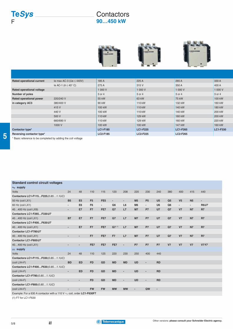
Other versions: please consult your Schneider Electric agency.5/8
5
Rated operational current Ie max AC-3 (Ue ≤ 440V) 185 A 225 A 265 A 330 A
Ie AC-1 (θ ≤ 40° C) 275 A 315 V 350 A 400 A
Rated operational voltage 1 000 V 1 000 V 1 000 V 1 000 V
Number of poles 3 or 4 3 or 4 3 or 4 3 or 4
Rated operational power 220/240 V 55 kW 63 kW 75 kW 100 kW
in category AC3 380/400 V 90 kW 110 kW 132 kW 160 kW
415 V 100 kW 110 kW 140 kW 180 kW
440 V 100 kW 110 kW 140 kW 200 kW
500 V 110 kW 129 kW 160 kW 200 kW
660/690 V 110 kW 129 kW 160 kW 220 kW
1000 V 100 kW 100 kW 147 kW 160 kW
Contactor type* LC1-F185 LC1-F225 LC1-F265 LC1-F330
Reversing contactor type* LC2-F185 LC2-F225 LC2-F265
* Basic reference to be completed by adding the coil voltage
Standard control circuit voltagesc c c c c supply
Volts 24 48 110 115 120 208 220 230 240 380 400 415 440
Contactors LC1-F115…F225(0.85…1.1UC)
50 Hz (coil LX1) B5 E5 F5 FE5 - - M5 P5 U5 Q5 V5 N5 -
60 Hz (coil LX1) - E6 F6 - G6 L6 M6 - U6 Q6 - - R6U7
40…400 Hz (coil LX9) - E7 F7 FE7 G7 L7 M7 P7 U7 Q7 V7 N7 R7
Contactors LC1-F265…F330U7
40…400 Hz (coil LX1) B7 E7 F7 FE7 G7 L7 M7 P7 U7 Q7 V7 N7 R7
Contactors LC1-F400…F630U7
40…400 Hz (coil LX1) - E7 F7 FE7 G7 (1) L7 M7 P7 U7 Q7 V7 N7 R7
Contactor LC1-F780U7
40…400 Hz (coil LX1) - - F7 FE7 F7 L7 M7 P7 U7 Q7 V7 N7 R7
Contactor LC1-F800U7
40…400 Hz (coil LX1) - - FE7 FE7 FE7 - P7 P7 P7 V7 V7 V7 V7Y7
a a a a a supply
Volts 24 48 110 125 220 230 250 400 440
Contactors LC1-F115…F330(0.85…1.1UC)
(coil LX4-F) BD ED FD GD MD MD UD - RD
Contactors LC1-F400…F630(0.85…1.1UC)
(coil LX4-F) - ED FD GD MD - UD - RD
Contactor LC1-F780(0.85…1.1UC)
(coil LX4-F) - - FD GD MD - UD - RD
Contactor LC1-F800(0.85…1.1UC)
(coil LX4-F) - - FW FW MW MW - QW -
Example: For a 630 A contactor with a 110 V c coil, order LC1-F630F7
(1) F7 for LC1-F630
TeSysF
Contactors90…450 kW

Other versions: please consult your Schneider Electric agency.5/9
5
Auxiliary contact blocks instantaneous dust & damp protected contacts time delay 1N/O + 1 N/C
Composition Reference Composition Reference Composition Reference Composition Reference Type Range Reference
N/O N/C N/O N/C N/O N/C N/O N/C
1 - LAD-N10 1 1 LAD-N11 2 2 LAD-N22 2 - - - LA1-DX20 On-delay 0.1…3 s LAD-T0
- 1 LAD-N01 2 - LAD-N20 1 3 LAD-N13 2 2 - - LA1-DY20 0.1…30 s LAD-T2
- 2 LAD-N02 4 - LAD-N40 2 - 2 - LA1-DZ40 10…180 s LAD-T4
- 4 LAD-N04 2 - 1 1 LA1-DZ31 1…30 s LAD-S2
3 1 LAD-N31 Off-delay 0.1…3 s LAD-R0
2 2 LAD-C22 0.1…30 s LAD-R2
10…180 s LAD-R4
Mounting accessories for 3-pole reversing contactors for motor control
2 identical contactors, horizontally mounted
Mechanical interlock with an electrical interlocking kit for the contactors
Contactor type Set of connections Mechanical interlock
LC1-F115 LA9-FF976 LA9-FF970
LC1-F150 LA9-F15076 LA9-FF970
LC1-F185 LA9-FG976 LA9-FG970
LC1-F225 LA9-F22576 LA9-FG970
LC1-F265 LA9-FH976 LA9-FJ970
LC1-F330 LA9-FJ976 LA9-FJ970
LC1-F400 LA9-FJ976 LA9-FJ970
LC1-F500 LA9-FK976 LA9-FJ970
LC1-F630 or LC1-F800 LA9-FL976 LA9-FL970
400 A 500 A 630 A 780 A 800 A
500 A 700 A 1 000 A 1 600 A 1 000 A
1 000 V 1 000 V 1 000 V 1 000 V 1 000 V
2, 3 or 4 2, 3 or 4 2, 3 or 4 3 or 4 3
110 kW 147 kW 200 kW 220 kW 250 kW
200 kW 250 kW 335 kW 400 kW 450 kW
220 kW 280 kW 375 kW 425 kW 450 kW
250 kW 295 kW 400 kW 425 kW 450 kW
257 kW 355 kW 400 kW 450 kW 450 kW
280 kW 335 kW 450 kW 475 kW 475 kW
185 kW 335 kW 450 kW 450 kW 450 kW
LC1-F400 LC1-F500 LC1-F630 LC1-F780 LC1-F800
For customer assembly
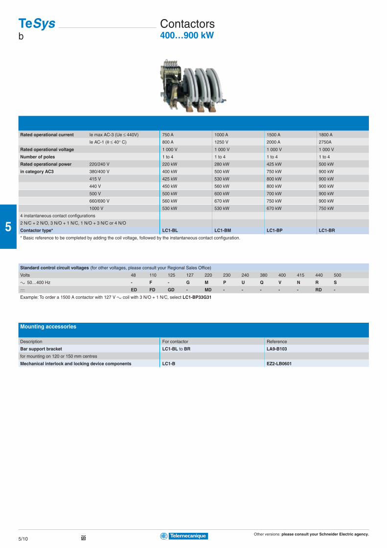
Other versions: please consult your Schneider Electric agency.5/10
5
Standard control circuit voltages (for other voltages, please consult your Regional Sales Office)
Volts 48 110 125 127 220 230 240 380 400 415 440 500
c 50…400 Hz - F - G M P U Q V N R S
a ED FD GD - MD - - - - - RD -
Example: To order a 1500 A contactor with 127 V c coil with 3 N/O + 1 N/C, select LC1-BP33G31
Mounting accessories
Description For contactor Reference
Bar support bracket LC1-BL to BR LA9-B103
for mounting on 120 or 150 mm centres
Mechanical interlock and locking device components LC1-B EZ2-LB0601
Rated operational current Ie max AC-3 (Ue ≤ 440V) 750 A 1000 A 1500 A 1800 A
Ie AC-1 (θ ≤ 40° C) 800 A 1250 V 2000 A 2750A
Rated operational voltage 1 000 V 1 000 V 1 000 V 1 000 V
Number of poles 1 to 4 1 to 4 1 to 4 1 to 4
Rated operational power 220/240 V 220 kW 280 kW 425 kW 500 kW
in category AC3 380/400 V 400 kW 500 kW 750 kW 900 kW
415 V 425 kW 530 kW 800 kW 900 kW
440 V 450 kW 560 kW 800 kW 900 kW
500 V 500 kW 600 kW 700 kW 900 kW
660/690 V 560 kW 670 kW 750 kW 900 kW
1000 V 530 kW 530 kW 670 kW 750 kW
4 instantaneous contact configurations
2 N/C + 2 N/O, 3 N/O + 1 N/C, 1 N/O + 3 N/C or 4 N/O
Contactor type* LC1-BL LC1-BM LC1-BP LC1-BR
* Basic reference to be completed by adding the coil voltage, followed by the instantaneous contact configuration.
TeSysb
Contactors400…900 kW
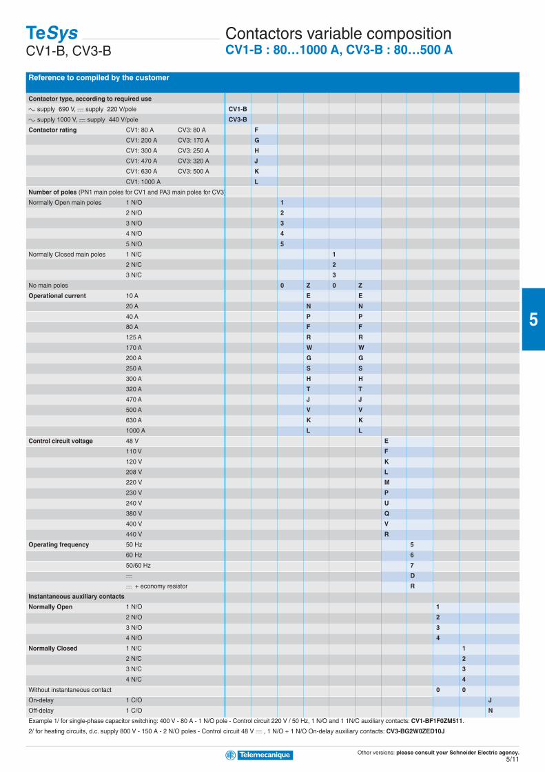
Other versions: please consult your Schneider Electric agency.5/11
5
Reference to compiled by the customer
Contactor type, according to required use
c supply 690 V, a supply 220 V/pole CV1-B
c supply 1000 V, a supply 440 V/pole CV3-B
Contactor rating CV1: 80 A CV3: 80 A F
CV1: 200 A CV3: 170 A G
CV1: 300 A CV3: 250 A H
CV1: 470 A CV3: 320 A J
CV1: 630 A CV3: 500 A K
CV1: 1000 A L
Number of poles (PN1 main poles for CV1 and PA3 main poles for CV3)
Normally Open main poles 1 N/O 1
2 N/O 2
3 N/O 3
4 N/O 4
5 N/O 5
Normally Closed main poles 1 N/C 1
2 N/C 2
3 N/C 3
No main poles 0 Z 0 Z
Operational current 10 A E E
20 A N N
40 A P P
80 A F F
125 A R R
170 A W W
200 A G G
250 A S S
300 A H H
320 A T T
470 A J J
500 A V V
630 A K K
1000 A L L
Control circuit voltage 48 V E
110 V F
120 V K
208 V L
220 V M
230 V P
240 V U
380 V Q
400 V V
440 V R
Operating frequency 50 Hz 5
60 Hz 6
50/60 Hz 7
a D
a + economy resistor R
Instantaneous auxiliary contacts
Normally Open 1 N/O 1
2 N/O 2
3 N/O 3
4 N/O 4
Normally Closed 1 N/C 1
2 N/C 2
3 N/C 3
4 N/C 4
Without instantaneous contact 0 0
On-delay 1 C/O J
Off-delay 1 C/O N
Example 1/ for single-phase capacitor switching: 400 V - 80 A - 1 N/O pole - Control circuit 220 V / 50 Hz, 1 N/O and 1 1N/C auxiliary contacts: CV1-BF1F0ZM511.
2/ for heating circuits, d.c. supply 800 V - 150 A - 2 N/O poles - Control circuit 48 V a , 1 N/O + 1 N/O On-delay auxiliary contacts: CV3-BG2W0ZED10J
TeSysCV1-B, CV3-B
Contactors variable compositionCV1-B : 80…1000 A, CV3-B : 80…500 A

Other versions: please consult your Schneider Electric agency.5/12
5
Thermal-magnetic circuit-breakers GV2-ME and GV2-P for connection by screw clamp terminalsGV2-ME with pushbutton control, GV2-P control by rotary knob
Standard power ratings of 3-phase motors 50/60 Hz in category AC-3 Setting range Magnetic Reference
400/415 V 500 V 690 V of thermal tripping
P Icu Ics (1) P Icu Ics (1) P Icu Ics (1) trips current
kW kA kW kA kW kA A A (d ± 20%)
- - - - - - - - - 0.1…0.16 1.5 GV2-ME01 GV2-P01
0.06 - - - - - - 0.16…0.25 2.4 GV2-ME02 GV2-P02
0.09 - - - - - - 0.25…0.40 5 GV2-ME03 GV2-P03
0.12 - - - 0.37 0.40…0.63 8 GV2-ME04 GV2-P04
0.18 - - - - - - 0.40…0.63 8 GV2-ME04 GV2-P04
0.25 - - - 0.55 - 0.63…1 13 GV2-ME05 GV2-P05
0.37 0.37 - - - 1…1.6 22.5 GV2-ME06 GV2-P06
0.55 0.55 0.75 1…1.6 22.5 GV2-ME06 GV2-P06
- - - 0.75 1.1 1…1.6 22.5 GV2-ME06 GV2-P06
0.75 1.1 1.5 3 75 1.6…2.5 33.5 GV2-ME07
0.75 1.1 1.5 8 100 1.6…2.5 33.5 GV2-P07
1.1 1.5 2.2 3 75 2.5…4 51 GV2-ME08
1.1 1.5 2.2 8 100 2.5…4 51 GV2-P08
1.5 2.2 3 3 75 2.5…4 51 GV2-ME08
1.5 2.2 3 3 100 2.5…4 51 GV2-P08
2.2 3 50 100 4 3 75 4…6.3 78 GV2-ME10
2.2 3 4 6 100 4…6.3 78 GV2-P10
3 4 10 100 5.5 3 75 6…10 138 GV2-ME14
3 4 50 100 5.5 6 100 6…10 138 GV2-P14
4 5.5 10 100 7.5 3 75 6…10 138 GV2-ME14
4 5.5 50 100 7.5 6 100 6…10 138 GV2-P14
5.5 15 50 7.5 6 75 9 3 75 9…14 170 GV2-ME16
5.5 7.5 42 75 9 6 100 9…14 170 GV2-P16
- - - - - - 11 3 75 9…14 170 GV2-ME16
- - - - - - 11 6 100 9…14 170 GV2-P16
7.5 15 50 9 6 75 15 3 75 13…18 223 GV2-ME20
7.5 50 50 9 10 75 15 4 100 13…18 223 GV2-P20
9 15 40 11 4 75 18.5 3 75 17…23 327 GV2-ME21
9 50 50 11 10 75 18.5 4 100 17…23 327 GV2-P21
11 15 40 15 4 75 - - - 20…25 327 GV2-ME22 (2)
11 50 50 15 10 75 - - - 20…25 327 GV2-P22
15 10 50 18.5 4 75 22 3 75 24…32 416 GV2-ME32
15 50 50 18.5 10 75 22 4 100 24…32 416 GV2-P32
> 100 kA
(1) as % of Icu
(2) combined with a recommended contactor
Thermal-magnetic circuit-breakers GV2-ME for connection by spring terminals
Add the figure 3 to the end of the reference. Example GV2-ME223 (available up to GV2-ME22)
TeSysGV2-ME, GV2-P
Thermal-magnetic circuit-breakers0.06…15 kW

Other versions: please consult your Schneider Electric agency.5/13
5
AccessoriesCombination block
For mounting on LC1-K or LP1-K LC1-D09…D38 LAD-31 and LC1-D09…D38
GV2-AF01 GV2-AF3 GV2-AF4
Sets of 3-pole busbars
63 A Pitch 45 mm 54 mm 72 mm
Number of tap-offs 2 GV2-G245 GV2-G254 GV2-G272
3 GV2-G345 GV2-G354
4 GV2-G445 GV2-G454 GV2-G472
5 GV2-G554
Protective end cover
For unused busbar outlets GV1-G10
Terminal blocks
For supply to one or more GV2-G busbar sets connection from the top can be fitted with current limiter GV1-L3 (GV2-ME and GV2-P)
GV1-G09 GV1-G05
Padlockable external operator for GV2-P (150 to 290 mm)
Padlocking In “On” and “Off” position In “Off” position
Handle black red
Legend plate blue yellow
IP 54 GV2-AP01 GV2-AP02
Padlocking device
For all GV2 devices For use with up to 6 padlocks (padlocks not supplied) Ø 6 mm shank max
GV2-V03
Add-on blocksContact blocks
Contact types N/O or N/C N/O + N/C N/O + N/O (fault) + N/C N/C + N/O C/O common
Instantaneous auxiliary contacts point
Mounting front GV-AE1 GV-AE11 GV-AE20
LH side GV-AN11 GV-AN20
Fault signalling contact + instantaneous auxiliary contact
LH side GV-AD1010 GV-AD1001 GV-AD0110
GV-AD0101
Short-circuit signalling contact
LH side GV-AM11
Electric trips
Undervoltage or shunt trips (1)
Side mounting (1 block on RH side of circuit-breaker) 50 Hz 60 Hz
Voltage 24 V GV-A•025 GV-A•026
48 V GV-A•055 GV-A•056
100 V GV-A•107
100…110 V GV-A•107
110…115 V GV-A•115 GV-A•116
120…127 V GV-A•125
127 V GV-A•115
200 V GV-A•207
200…220 V GV-A•207
220…240 V GV-A•225 GV-A•226
380…400 V GV-A•385 GV-A•386
415…440 V GV-A•415
415 V GV-A•416
(1) Undervoltage trips: replace the • with U, shunt trips: replace the • with S

Other versions: please consult your Schneider Electric agency.5/14
5
Thermal-magnetic circuit-breakers GV3-ME for connection by screw clamp terminalsPushbutton control
Standard power ratings of 3-phase motors 50/60 Hz in category AC-3 Setting range Reference
400/415 V 500 V 660/690 V of thermal
P Icu Ics (1) P Icu Ics (1) P Icu Ics (1) trips
kW kA kW kA kW kA A
0.37 100 100 0.37 100 100 0.75 100 100 1…1.6 GV3-ME06
0.55 100 100 0.55 100 100 1.1 100 100
0.75 100 100
0.75 100 100 1.1 100 100 1.5 100 100 1.6…2.5 GV3-ME07
1.1 100 100 1.5 100 100 2.2 4 100 2.5…4 GV3-ME08
1.5 100 100 2.2 100 100 3 4 100
2.2 100 100 3 100 100 4 4 100 4…6 GV3-ME10
3 100 100 4 8 100 5.5 4 100 6…10 GV3-ME14
4 100 100 5.5 8 100 7.5 4 100
7.5 100 50 9 8 100 9 4 100 10…16 GV3-ME20
11 4 100
9 100 50 11 8 100 15 4 100 16…25 GV3-ME25
11 100 50 15 8 100 18.5 4 100
15 35 50 18.5 8 75 22 4 75 25…40 GV3-ME40 (2)
18.5 35 50 22 8 75 30 4 75
22 35 50 30 8 75 37 4 75 40…63 GV3-ME63 (2)
30 35 50 37 8 75 45 4 75
37 15 50 45 4 100 55 2 100 56…80 GV3-ME80 (2)
(1) as % of Icu
(2) combined with a recommended contactor
TeSysGV3-ME
Thermal-magnetic circuit-breakers0.37…37 kW
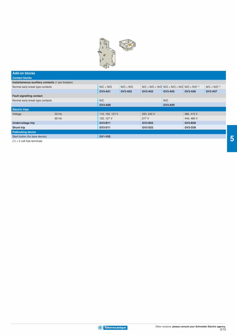
Other versions: please consult your Schneider Electric agency.5/15
5
Add-on blocksContact blocks
Instantaneous auxiliary contacts (1 per breaker)
Normal early break type contacts N/C + N/O N/O + N/O N/C + N/O + N/O N/O + N/O + N/O N/O + N/O (1) N/C + N/O (1)
GV3-A01 GV3-A02 GV3-A03 GV3-A05 GV3-A06 GV3-A07
Fault signalling contact
Normal early break type contacts N/C N/O
GV3-A08 GV3-A09
Electric trips
Voltage 50 Hz 110, 120, 127 V 220, 240 V 380, 415 V
60 Hz 120, 127 V 277 V 440, 480 V
Undervoltage trip GV3-B11 GV3-B22 GV3-B38
Shunt trip GV3-D11 GV3-D22 GV3-D38
Padlocking device
Start button (for bare device) GV1-V02
(1) + 2 volt free terminals
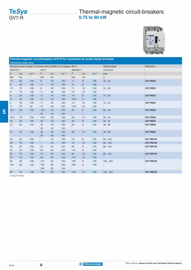
Other versions: please consult your Schneider Electric agency.5/16
5
Thermal-magnetic circuit-breakers GV7-R for connection by screw clamp terminalsControl by rocker lever
Standard power ratings of 3-phase motors 50/60 Hz in category AC-3 Setting range Reference
400/415 V 500 V 660/690 V of thermal
P Icu Ics (1) P Icu Ics (1) P Icu Ics (1) trips
kW kA kW kA kW kA A
7.5 25 100 9 18 100 11 8 100 12…20 GV7-RE20
9 25 100 11 18 100 15 8 100
7.5 70 100 9 50 100 11 10 100 12…20 GV7-RS20
9 70 100 11 50 100 15 10 100
9 25 100 11 18 100 15 8 100 15…25 GV7-RE25
11 25 100 15 18 100 18.5 8 100
9 70 100 11 50 100 15 10 100 15…25 GV7-RS25
11 70 50 15 50 100 18.5 10 100
18.5 25 100 18.5 18 100 22 8 100 25…40 GV7-RE40
22 18 100
18.5 70 100 18.5 50 100 22 10 100 25…40 GV7-RS40
22 25 100 30 18 100 30 8 100 30…50 GV7-RE50
37 25 100 45 18 100 55 8 100 48…80 GV7-RE80
55 18 100
37 70 100 45 50 100 55 10 100 48…80 GV7-RS80
55 50 100
45 25 100 - 18 100 75 8 100 60…100 GV7-RE100
45 70 100 - 50 100 75 10 100 60…100 GV7-RS100
55 35 100 75 30 100 90 8 100 90…150 GV7-RE150
75 70 100 90 30 100 110 8 100
55 70 100 75 50 100 90 10 100 90…150 GV7-RS150
75 70 100 90 50 100 110 10 100
90 35 100 110 30 100 160 8 100 132…220 GV7-RE220
110 35 100 132 30 100 200 8 100
160 30 100
90 70 100 110 50 100 160 10 100 132…220 GV7-RS220
(1) as % of Icu
TeSysGV7-R
Thermal-magnetic circuit-breakers0.75 to 90 kW
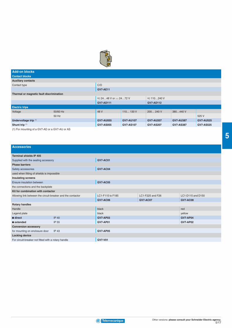
Other versions: please consult your Schneider Electric agency.5/17
5
Add-on blocksContact blocks
Auxiliary contacts
Contact type C/O
GV7-AE11
Thermal or magnetic fault discrimination
z 24…48 V or a 24…72 V z 110…240 V
GV7-AD111 GV7-AD112
Electric trips
Voltage 50/60 Hz 48 V 110… 130 V 200… 240 V 380…440 V
50 Hz 525 V
Undervoltage trip (1) GV7-AU055 GV7-AU107 GV7-AU207 GV7-AU387 GV7-AU525
Shunt trip (1) GV7-AS055 GV7-AS107 GV7-AS207 GV7-AS387 GV7-AS525
(1) For mounting of a GV7-AD or a GV7-AU or AS
Accessories
Terminal shields IP 405
Supplied with the sealing accessory GV7-AC01
Phase barriers
Safety accessories GV7-AC04
used when fitting of shields is impossible
Insulating screens
Ensure insulation between GV7-AC05
the connections and the backplate
Kit for combination with contactor
Allowing link between the circuit-breaker and the contactor LC1-F115 to F185 LC1-F225 and F26 LC1-D115 and D150
GV7-AC06 GV7-AC07 GV7-AC08
Rotary handles
Handle black red
Legend plate black yellow
direct IP 40 GV7-AP03 GV7-AP04
extended IP 55 GV7-AP01 GV7-AP02
Conversion accessory
for mounting on enclosure door IP 43 GV7-AP05
Locking device
For circuit-breaker not fitted with a rotary handle GV7-V01
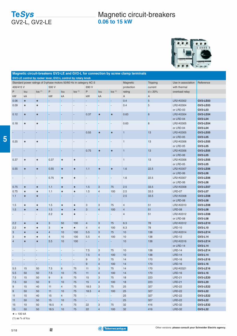
Other versions: please consult your Schneider Electric agency.5/18
5
Magnetic circuit-breakers GV2-LE and GV2-L for connection by screw clamp terminalsGV2-LE control by rocker lever, GV2-L control by rotary knob
Standard power ratings of 3-phase motors 50/60 Hz in category AC-3 Magnetic Tripping Use in association Reference
400/415 V 500 V 690 V protection current with thermal
P Icu Ics (1) P Icu Ics (1) P Icu Ics (1) rating d ± 20% overload relay
kW kA kW kA kW kA A A
0.06 - - - - - - 0.4 5 LR2-K0302 GV2-LE03
0.09 - - - - - - 0.4 5 LR2-K0304 GV2-LE03
or LRD-03 GV2-L03
0.12 - - - 0.37 0.63 8 LR2-K0304 GV2-LE04
or LRD-04 GV2-L04
0.18 - - - - - - 0.63 8 LR2-K0305 GV2-LE04
or LRD-04 GV2-L04
- - - - - - 0.55 1 13 LR2-K0305 GV2-LE05
or LRD-05 GV2-L05
0.25 - - - - - - 1 13 LR2-K0306 GV2-LE05
or LRD-05 GV2-L05
- - - - - - 0.75 1 13 LR2-K0306 GV2-LE05
or LRD-06 GV2-L05
0.37 0.37 - - - 1 13 LR2-K0306 GV2-LE05
or LRD-05 GV2-L05
0.55 0.55 1.1 1.6 22.5 LR2-K0307 GV2-LE06
or LRD-06 GV2-L06
- - - 0.75 - - - 1.6 22.5 LR2-K0307 GV2-LE06
or LRD-06 GV2-L06
0.75 1.1 1.5 3 75 2.5 33.5 LR2-K0308 GV2-LE07
0.75 1.1 1.5 4 100 2.5 33.5 LRD-07 GV2-L07
1.1 - - - - - - 2.5 33.5 LR2-K0308 GV2-LE08
or LRD-08 GV2-L08
1.5 1.5 3 3 75 4 51 LR2-K0310 GV2-LE08
1.5 1.5 3 4 100 4 51 LRD-08 GV2-L08
- - - 2.2 - - - 4 51 LR2-K0312 GV2-LE08
or LRD-08 GV2-L08
2.2 3 50 100 4 3 75 6.3 78 LR2-K0312 GV2-LE10
2.2 3 4 4 100 6.3 78 LRD-10 GV2-L10
3 4 10 100 5.5 3 75 10 138 LR2-K0314 GV2-LE14
3 4 10 100 5.5 4 100 10 138 LRD-12 GV2-L14
4 5.5 10 100 - - - 10 138 LR2-K0316 GV2-LE14
or LRD-14 GV2-L14
- - - - - - 7.5 3 75 10 138 LRD-14 GV2-LE14
- - - - - - 7.5 4 100 10 138 LRD-14 GV2-L14
- - - - - - 9 3 75 14 170 LRD-16 GV2-LE16
- - - - - - 9 4 100 14 170 LRD-16 GV2-L16
5.5 15 50 7.5 6 75 11 3 75 14 170 LR2-K0321 GV2-LE16
5.5 50 50 7.5 10 75 11 4 100 14 170 LRD-16 GV2-L16
7.5 15 50 9 6 75 15 3 75 18 223 LRD-21 GV2-LE20
7.5 50 50 9 10 75 15 4 100 18 223 LRD-21 GV2-L20
9 15 40 11 4 75 18.5 3 75 25 327 LRD-22 GV2-LE22
9 50 50 11 10 75 18.5 4 100 25 327 LRD-22 GV2-L22
11 15 40 15 4 75 - - - 25 327 LRD-22 GV2-LE22
11 50 50 15 10 75 - - - 25 327 LRD-22 GV2-L22
15 10 50 18.5 4 75 22 3 75 32 416 LRD-32 GV2-LE32
15 50 50 18.5 10 75 22 4 100 32 416 LRD-32 GV2-L32
> 100 kA
(1) as % of Icu
TeSysGV2-L, GV2-LE
Magnetic circuit-breakers0.06 to 15 kW
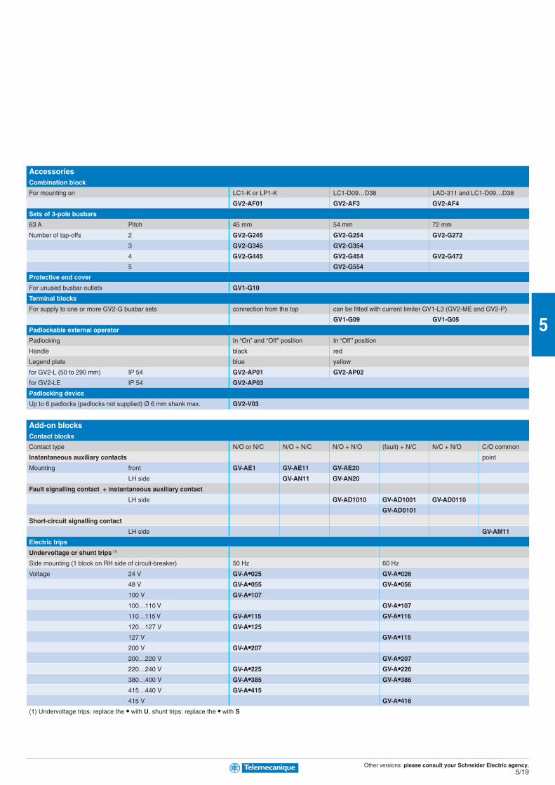
Other versions: please consult your Schneider Electric agency.5/19
5
AccessoriesCombination block
For mounting on LC1-K or LP1-K LC1-D09…D38 LAD-311 and LC1-D09…D38
GV2-AF01 GV2-AF3 GV2-AF4
Sets of 3-pole busbars
63 A Pitch 45 mm 54 mm 72 mm
Number of tap-offs 2 GV2-G245 GV2-G254 GV2-G272
3 GV2-G345 GV2-G354
4 GV2-G445 GV2-G454 GV2-G472
5 GV2-G554
Protective end cover
For unused busbar outlets GV1-G10
Terminal blocks
For supply to one or more GV2-G busbar sets connection from the top can be fitted with current limiter GV1-L3 (GV2-ME and GV2-P)
GV1-G09 GV1-G05
Padlockable external operator
Padlocking In “On” and “Off” position In “Off” position
Handle black red
Legend plate blue yellow
for GV2-L (50 to 290 mm) IP 54 GV2-AP01 GV2-AP02
for GV2-LE IP 54 GV2-AP03
Padlocking device
Up to 6 padlocks (padlocks not supplied) Ø 6 mm shank max. GV2-V03
Add-on blocksContact blocks
Contact type N/O or N/C N/O + N/C N/O + N/O (fault) + N/C N/C + N/O C/O common
Instantaneous auxiliary contacts point
Mounting front GV-AE1 GV-AE11 GV-AE20
LH side GV-AN11 GV-AN20
Fault signalling contact + instantaneous auxiliary contact
LH side GV-AD1010 GV-AD1001 GV-AD0110
GV-AD0101
Short-circuit signalling contact
LH side GV-AM11
Electric trips
Undervoltage or shunt trips (1)
Side mounting (1 block on RH side of circuit-breaker) 50 Hz 60 Hz
Voltage 24 V GV-A•025 GV-A•026
48 V GV-A•055 GV-A•056
100 V GV-A•107
100…110 V GV-A•107
110…115 V GV-A•115 GV-A•116
120…127 V GV-A•125
127 V GV-A•115
200 V GV-A•207
200…220 V GV-A•207
220…240 V GV-A•225 GV-A•226
380…400 V GV-A•385 GV-A•386
415…440 V GV-A•415
415 V GV-A•416
(1) Undervoltage trips: replace the • with U, shunt trips: replace the • with S

Other versions: please consult your Schneider Electric agency.5/20
5
Magnetic circuit-breakers GK3-EF for connection by screw clamp terminalsControl by rotary knob
Standard power ratings of 3-phase motors 50/60 Hz in category AC-3 Associated equipment Circuit-breaker
400/415 V 500 V 690 V Contactor Thermal Short-circuit
P Icu Ics P Icu Ics P Icu Ics min. size overload protection
kW kA kW kA kW kA relay Rating A Reference
15 50 30 18.5 20 30 - - - LC1-D32 LRD-32 40 GK3-EF40
- - - - - - 22 6 60 LC1-D40 LRD-3353 40 GK3-EF40
18.5 50 30 22 20 30 30 6 60 LC1-D40 LRD-3355 40 GK3-EF40
22 35 25 30 15 30 - - - LC1-D50 LRD-3357 65 GK3-EF65
- - - - - - 37 6 50 LC1-D65 LRD-3357 65 GK3-EF65
30 35 25 37 15 30 - - - LC1-D65 LRD-3359 65 GK3-EF65
30 35 25 37 15 30 - - - LC1-D65 LRD-3361 65 GK3-EF65
- - - - - - 45 6 50 LC1-D80 LRD-3359 65 GK3-EF65
37 35 25 45 15 30 - - - LC1-D80 LRD-3361 80 GK3-EF80
37 35 25 55 15 30 - - - LC1-D80 LRD-3363 80 GK3-EF80
Add-on blocksContact blocks
Contact types N/O N/O + N/O N/C + N/O N/C N/O
On-Off signalling contacts GK2-AX10 GK2-AX20 GK2-AX50
and “Control circuit test” function (1 or 2 blocks per device)
mounted on RH side of GK3-EF
Instantaneous fault signalling contacts GK2-AX12 GK2-AX22 GK2-AX52
(1 or 2 blocks per device) mounted on LH side of GK3-EF
Fault signalling contact (1) GV3-A08 GV3-A09
(1) 1 trip OR 1 fault signalling contact to be fitted inside the circuit-breaker.
AccessoriesPadlocking device
for padlocking the operator, with up to 3 padlocks (padlocks not supplied) GK3-AV01
External operator
for mounting on enclosure door. GK3-AP03
Red Ø 40 pushbutton on yellow plate, can be locked in
position O by means of up to 3 padlocks with door locked in
position I, and door locked in position O when padlocked
TeSysGK3-EF
Magnetic circuit-breakers15…37 kW

Other versions: please consult your Schneider Electric agency.5/21
5
Fuse carrier
Rated operational voltage with links, a.c. supply 480 V 480 V 690 V 690 V 690 V 690 V
Maximum continuous current for ambient temperature ≤ 40° C (1)
with links 20 20 32 32 50 125
with aM cartridge fuses 10 10 25 25 50 125
with gG cartridge fuses 20 20 30 30 40 100
Conforming to standards NF C 61-201 - - - -
IEC 947-3
Fuse carrier type DF6-AB08 GK1-C DF6-AB10 GK1-D GK1-E GK1-F
Fuse carrier
Composition 1 P 1 N 3 P + N 2 P 3 P 3 P + N
Size of cartridge fuse Rated thermal current
or link
8.5 x 31.5 20 A DF6-AB08 DF6-N10 GK1-CC GK1-CD GK1-CF GK1-CH
10 x 38 32 A DF6-AB10 DF6-N10 GK1-DC GK1-DD GK1-DF GK1-DH
14 x 51 50 A GK1-EB GK1-EN GK1-EC GK1-ED GK1-EF GK1-EH
22 x 58 125 A GK1-FB GK1-FN GK1-FC GK1-FD GK1-FF GK1-FH
Fuse carrier assembly strips
Number of fuse carriers to be assembled 2 3 4
Type DF6 GK1-AP2 GK1-AP3 GK1-AP4
GK1-E GK1-AP3 GK1-AP5 GK1-AP6
GK1-F GK1-AP4 GK1-AP6 GK1-AP9
Blown fuse indicators (neon)
For use on fuse carriers DF6, GK1-C, D and E
Operational voltage 80…400 V GK1-AS
TeSysDF6, GK1
Fuse carrier0…125 A
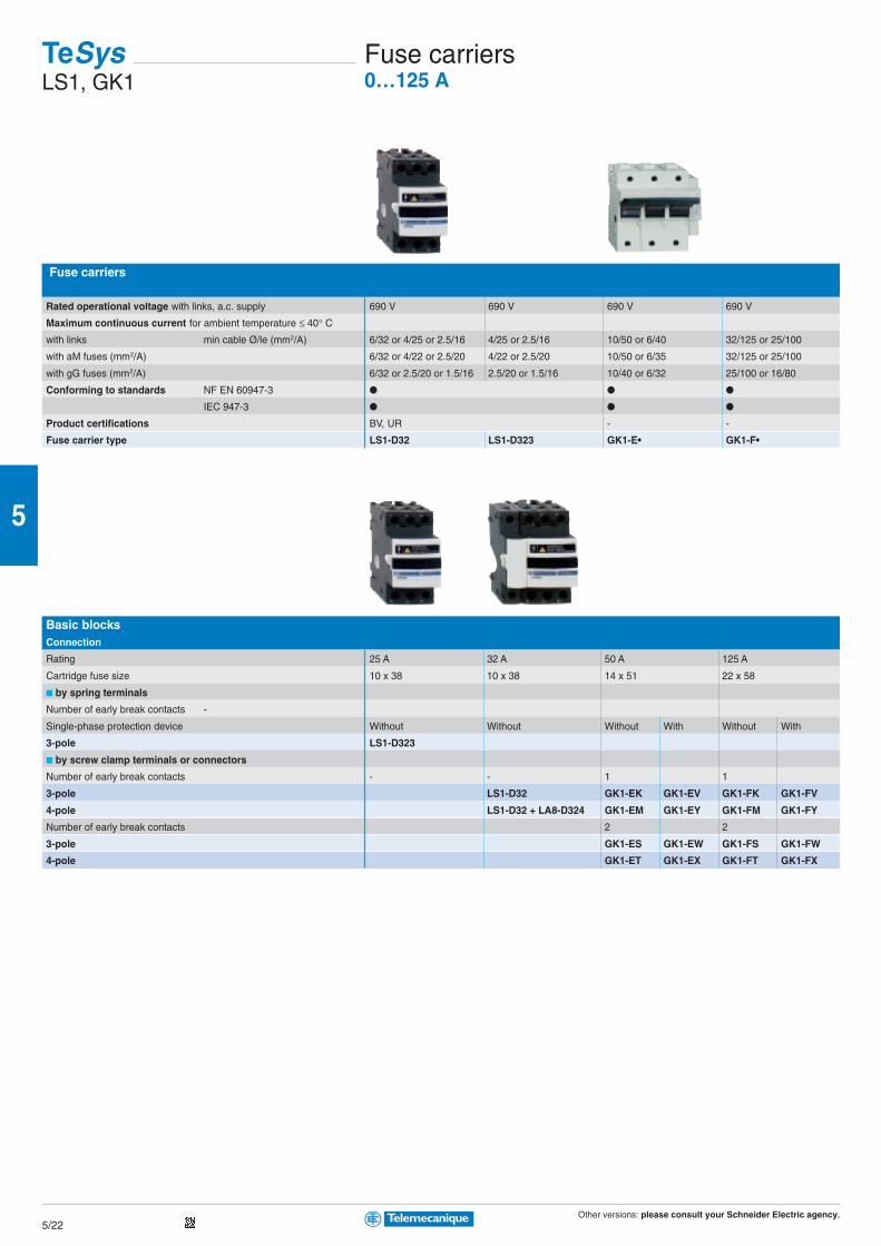
Other versions: please consult your Schneider Electric agency.5/22
5
-Fuse carriers
Rated operational voltage with links, a.c. supply 690 V 690 V 690 V 690 V
Maximum continuous current for ambient temperature ≤ 40° Cwith links min cable Ø/le (mm2/A) 6/32 or 4/25 or 2.5/16 4/25 or 2.5/16 10/50 or 6/40 32/125 or 25/100
with aM fuses (mm2/A) 6/32 or 4/22 or 2.5/20 4/22 or 2.5/20 10/50 or 6/35 32/125 or 25/100
with gG fuses (mm2/A) 6/32 or 2.5/20 or 1.5/16 2.5/20 or 1.5/16 10/40 or 6/32 25/100 or 16/80
Conforming to standards NF EN 60947-3
IEC 947-3
Product certifications BV, UR - -
Fuse carrier type LS1-D32 LS1-D323 GK1-E• GK1-F•
Basic blocksConnection
Rating 25 A 32 A 50 A 125 A
Cartridge fuse size 10 x 38 10 x 38 14 x 51 22 x 58
by spring terminals
Number of early break contacts -
Single-phase protection device Without Without Without With Without With
3-pole LS1-D323
by screw clamp terminals or connectors
Number of early break contacts - - 1 1
3-pole LS1-D32 GK1-EK GK1-EV GK1-FK GK1-FV
4-pole LS1-D32 + LA8-D324 GK1-EM GK1-EY GK1-FM GK1-FY
Number of early break contacts 2 2
3-pole GK1-ES GK1-EW GK1-FS GK1-FW
4-pole GK1-ET GK1-EX GK1-FT GK1-FX
TeSysLS1, GK1
Fuse carriers0…125 A
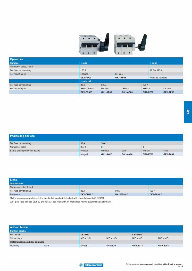
Other versions: please consult your Schneider Electric agency.5/23
5
OperatorsHandles side front
Number of poles, 3 or 4
For fuse carrier rating 125 A 32, 50, 125 A
For mounting on RH side LH side
GK1-AP07 GK1-AP08 Fitted as standard
external
For fuse carrier rating 32 A 50 A 125 A
For mounting on RH or LH side RH side LH side RH side LH side
DK1-FB005 GK1-AP05 GK1-AP06 GK1-AP07 GK1-AP08
Padlocking devices
For fuse carrier rating 32 A 50 A
Number of poles 3 or 4 3 4
Single-phase protection device Without Without With Without With
Integral GK1-AV07 GK1-AV08 GK1-AV08 GK1-AV09
LinksTubular links
Number of poles, 3 or 4
For fuse carrier rating 32 A 50 A 125 A
Reference DK1-CB92 (1) DK1-EB92 (2) DK1-FA92 (2)
(1) For use on a neutral circuit, the tubular link can be interlocked with special device LA8-D25906.
(2) 4-pole fuse carriers GK1-50 and 125 A 4 are fitted with an interlocked neutral tubular link as standard.
Add-on blocksContact blocks
For use on LS1-D32 LS1-D323
Contact type N/O + N/C N/O + N/O N/O + N/C N/O + N/O
Instantaneous auxiliary contacts
Mounting front GV-AE11 GV-AE20 GV-AE113 GV-AE203

Other versions: please consult your Schneider Electric agency.5/24
5
Switch-disconnector-fuse switch bodies for use with NF C or DIN fuses
Number of poles 3 3 + N (1) 3 4 3 4 3 4 3
Switch rating 32 A 50 A 63 A 100 A 125 A
Fuse size 10 x 38 14 x 51 00C (2) 22 x 58 22 x 58
Type of operator:
internal or external RH or LH side and front GS1-DD3 GS1-DD4
RH side GS1-FD3 GS1-FD4 GS1-GD3 GS1-GD4 GS1-JD3 GS1-JD4 GS1-KD3
external LH side GS1-FG3 GS1-FG4 GS1-GG3 GS1-GG4 GS1-JG3 GS1-JG4 GS1-KG3
front GS1-F3 GS1-F4 GS1-G3 GS1-G4 GS1-J3 GS1-J4 GS1-K3
internal and external front
for use with BS fuses
Switch rating 32 A 63 A 100 A 160 A
Fuse size A1 A2-A3 A4 Ø ≤ 31 mm A4 B1-B2
Type of operator:
internal or external RH or LH side and front GS1-DDB3 GS1-DDB4
RH side GS1-GBR3 GS1-GBR4 GS1-JBR3 GS1-JBR4 GS1-LLBR3 GS1-LLBR4 GS1-LBR3
external front
internal and external front GS1-DB3 GS1-DB4 GS1-GB3 GS1-GB4 GS1-JB3 GS1-JB4 GS1-LLB3 GS1-LLB4 GS1-LB3
(1) N = Switched Neutral
(2) Fuses for German market
Auxiliary “blown fuse” signalling contacts for use with NF C or DIN fuses
Contact type 1st C/O
Switch rating 50 A 100 and 125 A 160 A
Fuse size 14 x 51 22 x 58 T0
Number of poles 3 4 3 4 3 4
GS1-AF13 GS1-AF14 GS1-AF23 GS1-AF24 GS1-AF33 GS1-AF34
Auxiliary early break and/or signalling contacts
Switch rating 32 A 50…400 A 630…1250 A 50…400 V
Contact type 1 N/O 1 N/C 1 C/O 2 C/O 1 C/O 2 C/O 1 C/O 2 C/O 1 N/C + 1 N/O 2 N/C + 2 N/O
Standard contacts GS1-AM110 GS1-AM101 GS1-AM111 GS1-AM211 GS1-AM1 GS1-AM2 GS1-AM3 GS1-AM4 GS1-AN11 GS1-AN22
Contacts with test facility GS1-ANT11 GS1-ANT22
TeSysGS1
Switch-disconnector-fuses0…1250 A
Other versions: please consult your Schneider Electric agency.5/25
5
4 3 4 3 4 3 4 3 4 3 4 3 4 3 4
160 A 250 A 400 A 630 A 1250 A
Size 00 Size 0 Size 00 Size 1 Size 2 Size 3 Size 4
GS1-KD4 GS1-KKD3 GS1-KKD4 GS1-LD3 GS1-LD4 GS1-LLD3 GS1-LLD4 GS1-ND3 GS1-ND4 GS1-QQD3 GS1-QQD4 GS1-SD3 GS1-SD4 GS1-VD3 GS1-VD4
GS1-KG4 GS1-KKG3 GS1-KKG4 GS1-LG3 GS1-LG4 GS1-LLG3 GS1-LLG4 GS1-NG3 GS1-NG4 GS1-QQG3 GS1-QQG4
GS1-K4 GS1-KK3 GS1-KK4 GS1-L3 GS1-L4 GS1-LL3 GS1-LL4 GS1-N3 GS1-N4 GS1-QQ3 GS1-QQ4
GS1-S3 GS1-S4 GS1-V3 GS1-V4
200 A 250 A 315 A 400 V 630 A 800 A 1250 A
B1-B2 B1…B3 B1…B3 B1…B4 C1-C2 C1…C3 D1
GS1-LBR4 GS1-MMBR3 GS1-MMBR4 GS1-NBR3 GS1-NBR4 GS1-PPBR3 GS1-PPBR4 GS1-QQBR3 GS1-QQBR4 GS1-SBR3 GS1-SBR4 GS1-TBR3 GS1-TRB4 GS1-VRB3 GS1-VRB4
GS1-LB4 GS1-MMB3 GS1-MMB4 GS1-NB3 GS1-NB4 GS1-PPB3 GS1-PPB4 GS1-QQB3 GS1-QQB4
GS1-SB3 GS1-SB4 GS1-TB3 GS1-TB4 GS1-VB3 GS1-VB4
2nd C/O
250 and 400 A 630 A 1250 A 50…400 A 630…1250 A
T1 and T2 T3 T4 - -
3 4 3 4 3 4 3 4 3 4
GS1-AF43 GS1-AF44 GS1-AF63 GS1-AF64 GS1-AF73 GS1-AF74 GS1-AF GS1-AF GS1-AFF GS1-AFF

Other versions: please consult your Schneider Electric agency.5/26
5
Thermal overload relays, model dadjustable from 0.1 to 140 A
Compensated relays with manual or automatic reset, with relay trip indicator, for a.c. or d.c.
Relay setting range Fuses to be used with selected relay With contactor Reference
aM gG BS88
Class 10 A 0.10…0.16 A 0.25 A 2 A - LC1-D09…D38 LRD-01
0.16…0.25 A 0.5 A 2 A - LC1-D09…D38 LRD-02
0.25…0.40A 1 A 2 A - LC1-D09…D38 LRD-03
0.40…0.63 A 1 A 1.6 A - LC1-D09…D38 LRD-04
0.63…1 A 2 A 4 A - LC1-D09…D38 LRD-05
1…1.7 A 2 A 4 A 6 A LC1-D09…D38 LRD-06
1.6…2.5 A 4 A 6 A 10 A LC1-D09…D38 LRD-07
2.5…4 A 6 A 10 A 16 A LC1-D09…D38 LRD-08
4…6 A 8 A 16 A 16 A LC1-D09…D38 LRD-10
5.5…8 A 12 A 20 A 20 A LC1-D09…D38 LRD-12
7…10 A 12 A 20 A 20 A LC1-D09…D38 LRD-14
9…13 A 16 A 25 A 25 A LC1-D12…D38 LRD-16
12…18 A 20 A 35 A 32 A LC1-D18…D38 LRD-21
16…24 A 25 A 50 A 50 A LC1-D25…D38 LRD-22
23…32 A 40 A 63 A 63 A LC1-D25…D38 LRD-32
30…38 A 50 A 80 A 80 A LC1-D32 and D38 LRD-35
17…25 A 25 A 50 A 50 A LC1-D40…D95 LRD-3322
23…32 A 40 A 63 A 63 A LC1-D40…D95 LRD-3353
30…40 A 40 A 100 A 80 A LC1-D40…D95 LRD-3355
37…50 A 63 A 100 A 100 A LC1-D40…D95 LRD-3357
48…65 A 63 A 100 A 100 A LC1-D50…D95 LRD-3359
55…70 A 80 A 125 A 125 A LC1-D50…D95 LRD-3361
63…80 A 80 A 125 A 125 A LC1-D65 and D95 LRD-3363
80…104 A 100 A 160 A 160 A LC1-D80 and D95 LRD-3365
80…104 A 125 A 200 A 160 A LC1-D115 and D150 LRD-4365
95…120 A 125 A 200 A 200 A LC1-D115 and D150 LRD-4367
110…140 A 160 A 250 A 200 A LC1-D150 LRD-4369
80…104 A 100 A 160 A 160 A (1) LRD-33656
95…120 A 125 A 200 A 200 A (1) LRD-33676
110…140 A 160 A 250 A 200 A (1) LRD-33696
Class 20 A 6 A 10 A 16 A LC1-D09…D32 LRD-1508
4…6 A 8 A 16 A 16 A LC1-D09…D32 LRD-1510
5.5…8 A 12 A 20 A 20 A LC1-D09…D32 LRD-1512
7…10 A 16 A 20 A 25 A LC1-D09…D32 LRD-1514
9…13 A 16 A 25 A 25 A LC1-D12…D32 LRD-1516
12…18 A 25 A 35 A 40 A LC1-D18…D32 LRD-1521
17…25 A 32 A 50 A 50 A LC1-D25 and D32 LRD-1522
23…28 A 40 A 63 A 63 A LC1-D25 and D32 LRD-1530
25…32 A 40 A 63 A 63 A LC1-D25 and D32 LRD-1532
17…25 A 32 A 50 A 50 A LC1-D40…D95 LR2-D3522
23…32 A 40 A 63 A 63 A LC1-D40…D95 LR2-D3553
30…40 A 50 A 100 A 80 A LC1-D40…D95 LR2-D3555
37…50 A 63 A 100 A 100 A LC1-D50…D95 LR2-D3557
48…65 A 80 A 125 A 100 A LC1-D50…D95 LR2-D3559
55…70 A 100 A 125 A 125 A LC1-D65…D95 LR2-D3561
63…80 A 100 A 160 A 125 A LC1-D80 and D95 LR2-D3563
(1) Independent mounting
Screw clamp terminal connections or connectors. For spring terminal connections on LRD-01 to LRD-22, add 3 to the end of the reference. Example: LRD-01 becomes LRD-013.
For lug-clamp connections, add 6 to the end of the reference. Example: LRD-01 becomes LRD-016.
For thermal overload relays for use with class 10 A unbalanced loads, with connection by screw clamp terminals, change the prefix in the references above from LRD (except
LRD-4•••) to LR3-D. Example LRD-01 becomes LR3-D01.
TeSysd
Thermal overload relays0.1…140 A
Other versions: please consult your Schneider Electric agency.5/27
5
Thermal overload relays, model kadjustable from 0.11 to 12 A
Connection by screw clamp terminals, direct mounting on contactors LC1-K, manual or automatic reset
Relay setting range Fuses to be used with selected relay Reference
Class 10 A aM gG BS88
0.11…0.16 A 0.25 A 0.5 A - LR2-K0301
0.16…0.23 A 0.25 A 0.5 A - LR2-K0302
0.23…0.36 A 0.5 A 1 A - LR2-K0303
0.36…0.54 A 1 A 1.6 A - LR2-K0304
0.54…0.8 A 1 A 2 A - LR2-K0305
0.8…1.2 A 2 A 4 A 6 A LR2-K0306
1.2…1.8 A 2 A 6 A 6 A LR2-K0307
1.8…2.6 A 2 A 6 A 10 A LR2-K0308
2.6…3.7 A 4 A 10 A 16 A LR2-K0310
3.7…5.5 A 6 A 16 A 16 A LR2-K0312
5.5…8 A 8 A 20 A 20 A LR2-K0314
8…11.5 A 10 A 25 A 20 A LR2-K0316
Thermal overload relays for use on class 10 A unbalanced loads: for above references LR2-K0305 to LR2-K0316 only, replace the prefix LR2 with LR7.
Example LR7-K0310.
AccessoriesPrewiring kit
Allowing direct connection of the N/C contact For use on
of relay LRD-01…35 or LR3-D01… D35 to the contactor LC1-D09…D18 LAD-7C1
LC1-D25…D38 LAD-7C2
Terminal blocks (1)
For clip-on mounting on 35 mm mounting rail (AM1-DP200) LRD-01…35 and LR3-D01…D35 LAD-7B10
or screw fixing LRD-3•••, LR3-D3•••, LRD-35•• LA7-D3064 (2)
For independent mounting of the relay LR2-K•••• LA7-K0064
Terminal block adapter
For mounting a relay beneath an LC1-D115 or D150 contactor LRD-3•••, LR3-D3•••, LRD-35•• LA7-D3058
Stop or electrical reset
Remote (3) LRD-01…35 and LR3-D01…D35 LAD-703• (4)
Tripping or electrical reset device
Remote (3) All relays except LRD-01…35 and LR3-D01…D35 LA7-D03• (4)
(1) Terminal blocks are supplied with terminals protected against direct finger contact and screws in the open “ready-to-tighten” position.
(2) To order a terminal block for connection by lug-clamps, the reference becomes LA7-D30646.
(3) The time for which the coil of remote tripping or electrical resetting device LA7-D03 or LAD-703 can remain energised depends on its rest time: 1 s pulse duration with 9 s rest
time; maximum pulse duration of 20 s with a rest time of 300 s. Minimum pulse time 200 ms.
(4) Reference to be completed by adding the code indicating the control circuit voltage.
Standard control circuit voltagesc c c c c supply
Volts 12 24 48 96 110 220/230 380/400 415/440
50/60 Hz. Consumption, inrush and sealed < 100 VA - B E - F M Q N
a a a a a supply
Consumption, inrush and sealed < 100 W J B E DD F M - -
TeSysk
Thermal overload relays0.11…11.5 A
Other versions: please consult your Schneider Electric agency.5/28
5
For use with contactor LC1-D LC1-F
Motor current 60…150 A 30…630 A
Basic reference, to be completed LR9-D LR9-F
Relay setting range Fuse to be used with selected relay For mounting Compensated and differential
beneath contactor LC1- or not with alarm
aM gG Class 10 Class 20 Class 10 or 20
60…100 100 160 D115 and D150 LR9-D5367 LR9-D5567
90…150 160 250 D115 and D150 LR9-D5369 LR9-F5569
30…50 50 80 F115…F185 LR9-F5357 LR9-F5557 LR9-F57
48…80 80 125 F115…F185 LR9-F5363 LR9-F5563 LR9-F63
60…100 100 200 F115…F185 LR9-F5367 LR9-F5567 LR9-F67
90…150 160 250 F115…F185 LR9-F5369 LR9-F5569 LR9-F69
132…220 250 315 F185…F400 LR9-F5371 LR9-F5571 LR9-F71
200…330 400 500 F225…F500 LR9-F7375 LR9-F7575 LR9-F75
300…500 500 800 F225…F500 LR9-F7379 LR9-F7579 LR9-F79
380…630 630 800 F400…F630 and F800 LR9-F7381 LR9-F7581 LR9-F81
AccessoriesRemote control
Function Reset Stop and/or Reset
Electrical reset (1) LA7-D03• (2)
Reset by flexible cable (length 0.5 m) LA7-D305
Adapter for door interlock mechanism LA7-D1020
Operating head for pushbutton
Spring return ZA2-BL639 ZA2-BL432
Rod with snap-off end
Adjustable from 17 to 120 mm ZA2-BZ13
Insulated terminal blocks
For relays LR9-F5•57, F5•63, F5•67, F5•69, F57, F63, F67 and F69 Set of 2 blocks
LA9-F103
(1) The time for which the coil of remote electrical reset device LA7-D03 can remain energised depends on its rest time: 1 s pulse with 9 s rest time; 5 s pulse duration with 30 s
rest time; 10 s pulse duration with 90 s rest time: maximum pulse duration 20 s with rest time of 300 s. Minimum pulse time: 200 ms.
(2) Reference to be completed by adding the coil voltage code, see page 5/27
TeSysLR9
Electronic thermal overload relays60…630 A

Other versions: please consult your Schneider Electric agency.5/29
5
Relay type Electronic over current relaysmodel LR97D
Relay setting range 0,3…1,5 A 1,2…7 A 5…25 A 20…38 A
For use with contactor LC1D09…D38 LC1D25…D38
References 200… 240 VAC LR97D015M7 LR97D07M7 LR97D025M7 LR97D038M7
100… 120 VAC LR97D015F7 LR97D07F7 LR97D025F7 LR97D038F7
24 VAC/DC LR97D015B LR97D07B LR97D025B LR97D038B
48 VAC/DC LR97D015E LR97D07E LR97D025E LR97D038E
0,5…60 A
Relay type Electronic over current relaysmodel LT47 with manual reset
Relay setting range 0,5…6 A 3…30 A 5…60 A
References 200… 240 VAC LT4706M7S LT47D30M7S LT4760M7S
100… 120 VAC LT47D06F7S LT47D30F7S LT4760F7S
24 VAC/DC LT47D06BS LT47D30BS LT4760BS
48 VAC/DC LT47D06ES LT47D30ES LT4760ES
Relay type Electronic over current relaysmodel LT47 with automatic reset
Relay setting range 0,5…6 A 3…30 A 5…60 A
References 200… 240 VAC LT4706M7A LT47D30M7A LT4760M7A
100… 120 VAC LT47D06F7A LT47D30F7A LT4760F7A
24 VAC/DC LT47D06BA LT47D30BA LT4760BA
48 VAC/DC LT47D06EA LT47D30EA LT4760EA
Accessories : please consult your Schneider Electric agency.
TeSysLR/LT
Electronic over current relays0,3…38 A
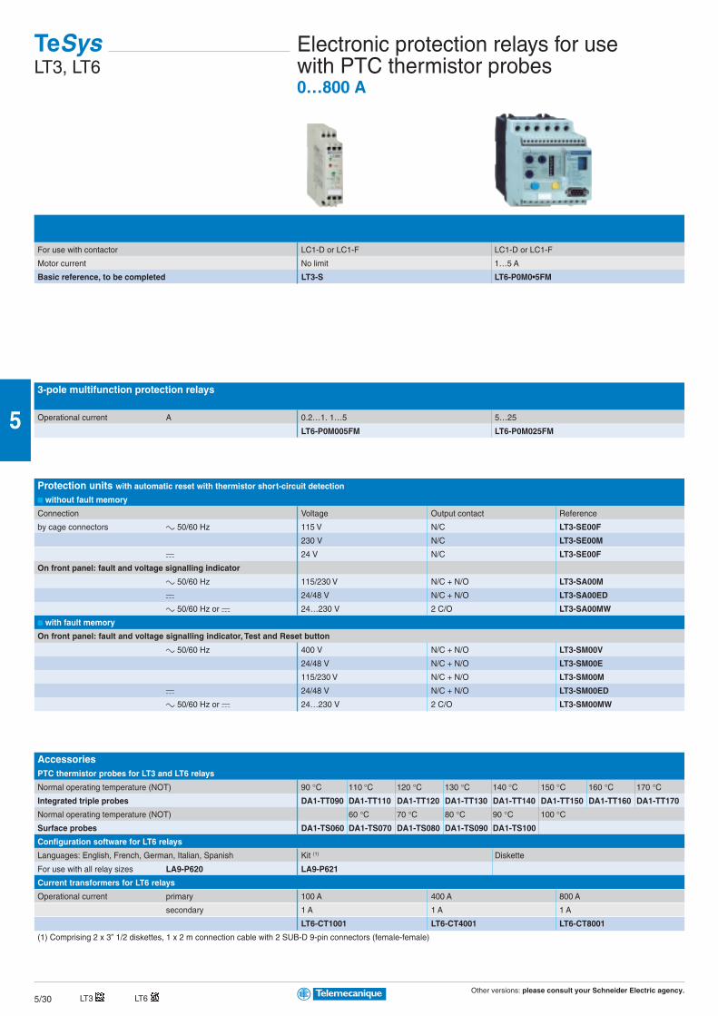
Other versions: please consult your Schneider Electric agency.5/30
5
For use with contactor LC1-D or LC1-F LC1-D or LC1-F
Motor current No limit 1…5 A
Basic reference, to be completed LT3-S LT6-P0M0•5FM
3-pole multifunction protection relays
Operational current A 0.2…1. 1…5 5…25
LT6-P0M005FM LT6-P0M025FM
Protection units with automatic reset with thermistor short-circuit detection
without fault memory
Connection Voltage Output contact Reference
by cage connectors c 50/60 Hz 115 V N/C LT3-SE00F
230 V N/C LT3-SE00M
a 24 V N/C LT3-SE00F
On front panel: fault and voltage signalling indicator
c 50/60 Hz 115/230 V N/C + N/O LT3-SA00M
a 24/48 V N/C + N/O LT3-SA00ED
c 50/60 Hz or a 24…230 V 2 C/O LT3-SA00MW
with fault memory
On front panel: fault and voltage signalling indicator, Test and Reset button
c 50/60 Hz 400 V N/C + N/O LT3-SM00V
24/48 V N/C + N/O LT3-SM00E
115/230 V N/C + N/O LT3-SM00M
a 24/48 V N/C + N/O LT3-SM00ED
c 50/60 Hz or a 24…230 V 2 C/O LT3-SM00MW
AccessoriesPTC thermistor probes for LT3 and LT6 relays
Normal operating temperature (NOT) 90 °C 110 °C 120 °C 130 °C 140 °C 150 °C 160 °C 170 °CIntegrated triple probes DA1-TT090 DA1-TT110 DA1-TT120 DA1-TT130 DA1-TT140 DA1-TT150 DA1-TT160 DA1-TT170
Normal operating temperature (NOT) 60 °C 70 °C 80 °C 90 °C 100 °CSurface probes DA1-TS060 DA1-TS070 DA1-TS080 DA1-TS090 DA1-TS100
Configuration software for LT6 relays
Languages: English, French, German, Italian, Spanish Kit (1) Diskette
For use with all relay sizes LA9-P620 LA9-P621
Current transformers for LT6 relays
Operational current primary 100 A 400 A 800 A
secondary 1 A 1 A 1 A
LT6-CT1001 LT6-CT4001 LT6-CT8001
(1) Comprising 2 x 3” 1/2 diskettes, 1 x 2 m connection cable with 2 SUB-D 9-pin connectors (female-female)
TeSysLT3, LT6
Electronic protection relays for usewith PTC thermistor probes0…800 A
LT6LT3

Other versions: please consult your Schneider Electric agency.5/31
5
1/L1
2/T
1
3/L2
4/T
2
5/L3
6/T
3
1/L1
2/T
1
3/L2
4/T
2
5/L3
6/T
3
Vario Protection components 12…175 ASwitch disconnectors
Type Mini-Vario for standard applicationsMounting door Backplate mounting in enclosure
Colour handle / Front plate Red / Yellow Black / Black Red / Yellow
Front plate dimensions (mm) 60 x 60 60 x 60
Fixing Ø 22.5 mm Ø 22.5 mm
Degree of protection IP 20 IP 20
Rated operational voltage (Ue) 690 V 690 V
Thermal current in open air (Ith) 12 A VCDN12 VBDN12 VCCDN12
20 A VCDN20 VBDN20 VCCDN20
Type Vario for high performance applicationsMounting door Backplate mounting in enclosure
Colour handle / Front plate Red / Yellow Black / Black Red / Yellow Black / Black Red / Yellow
Front plate dimensions (mm) 60 x 60 60 x 60 90 x 90 60 x 60 90 x 90
Fixing Ø 22,5 mm 4 screws 4 screws Ø 22,5 mm 4 screws 4 screws
Degree of protection IP 20 IP 20 IP 20 IP 20 IP 20 IP 20
Rated operational voltage (Ue) 690 V 690 V 690 V 690 V 690 V 690 V
Thermal current in open air (Ith) 12 A VCD02 VBD02 VCF02 VBF02 – VCCD02 VCCF02 –
20 A VCD01 VBD01 VCF01 VBF01 – VCCD01 VCCF01 –
25 A VCD0 VBD0 VCF0 VBF0 – VCCD0 VCCF0 –
32 A VCD1 VBD1 VCF1 VBF1 – VCCD1 VCCF1 –
40 A VCD2 VBD2 VCF2 VBF2 – VCCD2 VCCF2 –
63 A – – VCF3 VBF3 – – VCCF3 –
80 A – – VCF4 VBF4 – – VCCF4 –
125 A – – – – VCF5 – – VCCF5
175 A – – – – VCF6 – – VCCF6
Add-on modules For mini-Vario For VarioMain pole modules
Rating 12 A 20 A 12 A 20 A 25 A 32 A 40 A 63 A 80 A
References VZN12 VZN20 VZ02 VZ01 VZ0 VZ1 VZ2 VZ3 VZ4
Neutral pole module with early make and late break contacts
Rating 12…20 A 12…40 A 63 and 80 A 125 and 175 A
References VZN11 VZ11 VZ12 VZ13
Earthing module
References VZN14 VZ14 VZ15 VZ16
Auxiliary contact block modules
Contact types N/O N/C N/O + N/C N/O + N/O
References VZN05 VZN06 VZ7 VZ20

Other versions: please consult your Schneider Electric agency.5/32
5
D.O.L. starterswith circuit-breaker with fuse protection
Level of service Coordination: Type 1 Type 2
Power at 400 V Up to: 5.5 kW 15 kW 37 kW
Type of components Combination automatic motor starter with overload protection Fuse carrier +
incorporated in the circuit-breaker plate-mounted contactor
Basic reference, to be completed GV2-ME GV2-DM GV2-DP LC4-D
Starters GV2-MENon-reversing Reversing
Standard power ratings Setting Fixed For customer assembly Factory assembled
of 3-phase motors range of magnetic Motor Contactor Basic reference, to be completed with
50/60 Hz in category AC-3 (kW) thermal trips tripping current circuit-breaker code indicating control circuit voltage
400/415 V 440 V 500 V 13 Irth
0.37 0.37 0.37 1…1.6 22.5 GV2-ME06 LC1-K06 GV2-ME06K1•• GV2-ME06K2••
0.55 0.55 0.55
- - 0.75
0.75 0.75 - 1.6…2.5 33.5 GV2-ME07 LC1-K06 GV2-ME07K1•• GV2-ME07K2••
- 1.1 1.1
1.1 - 1.5 2.5…4 51 GV2-ME08 LC1-K06 GV2-ME08K1•• GV2-ME08K2••
1.5 1.5 2.2
2.2 2.2 - 4…6.3 78 GV2-ME10 LC1-K06 GV2-ME10K1•• GV2-ME10K2••
- - 3
3 - 4 6…10 138 GV2-ME14 LC1-K09 GV2-ME14K1•• GV2-ME14K2••
4 4 5.5
5.5 5.5 7.5 9…14 170 GV2-ME16 LC1-K12 GV2-ME16K1•• GV2-ME16K2••
Standard control circuit voltages (for other voltages, please consult your Regional Sales Office)
Volts 24 110 220/230 230 230/240 380/400
c 50…400 Hz B7 F7 M7 P7 U7 Q7
a (1) BW3 - - - - -
(1) Low consumption coil (1.5 W), wide range (0.7…1.3 Uc) and with integral suppression device as standard.
TeSysGV2, LC
Combination motor starters0.06…15 kW

Other versions: please consult your Schneider Electric agency.5/33
5
D.O.L. starters GV2-DM and GV2-DPNon-reversing Reversing
Standard power ratings Setting Fixed For customer assembly Factory assembled
of 3-phase motors range of magnetic Motor Contactor Basic reference, to be completed with
50/60 Hz in category AC-3 (kW) thermal trips tripping current circuit-breaker code indicating control circuit voltage
400/415 V 440 V 500 V 13 Irth
0.06 0.06 - 0.16…0.25 2.4 GV2-ME02 LC1-D09•• GV2-DM102•• GV2-DM202••
GV2-P02 LC1-D09•• GV2-DP102•• GV2-DP202••
0.09 0.09 - 0.25…0.40 5 GV2-ME03 LC1-D09•• GV2-DM103•• GV2-DM203••
- 0.12 - GV2-P03 LC1-D09•• GV2-DP103•• GV2-DP203••
0.12 - - 0.40…0.63 8 GV2-ME04 LC1-D09•• GV2-DM104•• GV2-DM204••
0.18 0.18 - GV2-P04 LC1-D09•• GV2-DP104•• GV2-DP204••
0.25 0.25 - 0.63…1 13 GV2-ME05 LC1-D09•• GV2-DM105•• GV2-DM205••
0.37 0.37 - GV2-P05 LC1-D09•• GV2-DP105•• GV2-DP205••
- - 0.37 1…1.6 22.5 GV2-ME06 LC1-D09•• GV2-DM106•• GV2-DM206••
0.55 0.55 0.55 GV2-P06 LC1-D09•• GV2-DP106•• GV2-DP206••
- - 0.75
0.75 0.75 - 1.6…2.5 33.5 GV2-ME07 LC1-D09•• GV2-DM107•• GV2-DM207••
- 1.1 1.1 GV2-P07 LC1-D09•• GV2-DP107•• GV2-DP207••
1.1 - 1.5 2.5…4 51 GV2-ME08 LC1-D09•• GV2-DM108•• GV2-DM208••
1.5 1.5 2.2 GV2-P08 LC1-D09•• GV2-DP108•• GV2-DP208••
2.2 2.2 - 4…6.3 78 GV2-ME10 LC1-D09•• GV2-DM110•• GV2-DM210••
- 3 3 GV2-P10 LC1-D09•• GV2-DP110•• GV2-DP210••
3 - 4 6…10 138 GV2-ME14 LC1-D09•• GV2-DM114•• GV2-DM214••
4 4 5.5 GV2-P14 LC1-D09•• GV2-DP114•• GV2-DP214••
5.5 5.5 7.5 9…14 170 GV2-ME16 LC1-D12•• GV2-DM116•• GV2-DM216••
- 7.5 9 GV2-P16 LC1-D25•• GV2-DP116•• GV2-DP216••
7.5 9 - 13…18 223 GV2-ME20 LC1-D18•• GV2-DM120•• GV2-DM220••
GV2-P20 LC1-D25•• GV2-DP120•• GV2-DP220••
9 11 11 17…23 327 GV2-ME21 LC1-D25•• GV2-DM121•• GV2-DM221••
GV2-P21 LC1-D25•• GV2-DP121•• GV2-DP221••
11 - 15 20…25 327 GV2-ME22 LC1-D25•• GV2-DM122•• GV2-DM222••
GV2-P22 LC1-D25•• GV2-DP122•• GV2-DP222••
15 15 18.5 24…32 416 GV2-ME32 LC1-D32•• GV2-DM132•• GV2-DM232••
GV2-P32 LC1-D32•• GV2-DP132•• GV2-DP232•
Standard control circuit voltages (for other voltages, please consult your Regional Sales Office)
Volts 24 220 230
c 50…400 Hz B7 M7 P7
a (1) BD - -
(1) Low consumption coil (1.5 W), wide range (0.7…1.3 Uc) with integral suppression device as standard.

Other versions: please consult your Schneider Electric agency.5/34
5
Power basefor D.O.L. starter Non reversing Reversing
Connection by screw clamp terminals
Rated operational voltage ≤ 440 V ≤ 500 V ≤ 690 V ≤ 440 V ≤ 500 V ≤ 690 V
Power 12 A 12 A 9 A 12 A 12 A 9 A
LUB-12 LU2B-12••
Power 32 A 23 A 21 A 32 A 23 A 21 A
LUB-32 LU2B-32••
Add-on blocksContact blocks
Signalling Contact
status of starter-controller power poles N/O (53-54)
fault N/C (95-96) N/C (95-96) N/O (97-98)
control handle in position O N/O (17-18) N/O (17-18)
Connection Item 1 1 1 1 1 1
screw clamp terminals 1 + 2 LUA1-D11 LUA1-C11 LUA1-C20
without connections 1 LUA1-D110 LUA1-C110 LUA1-C200
Auxiliary contact blocks
N/O N/C N/O N/C N/O N/C
2 - 1 1 - 2
screw clamp terminals 3 LUF-N20 LUF-N11 LUF-N02
Modules
parallel wiring LUF-C00
alarm LUF-W10
communication As-i Modbus
ASILUF-C5 LUL-C033
indication of motor load 4…20 mA
LUF-V2
fault differentiation and reset manual reset automatic reset
LUF-DH11 LUF-DA10
TeSysU
Starter-controller0…32 A
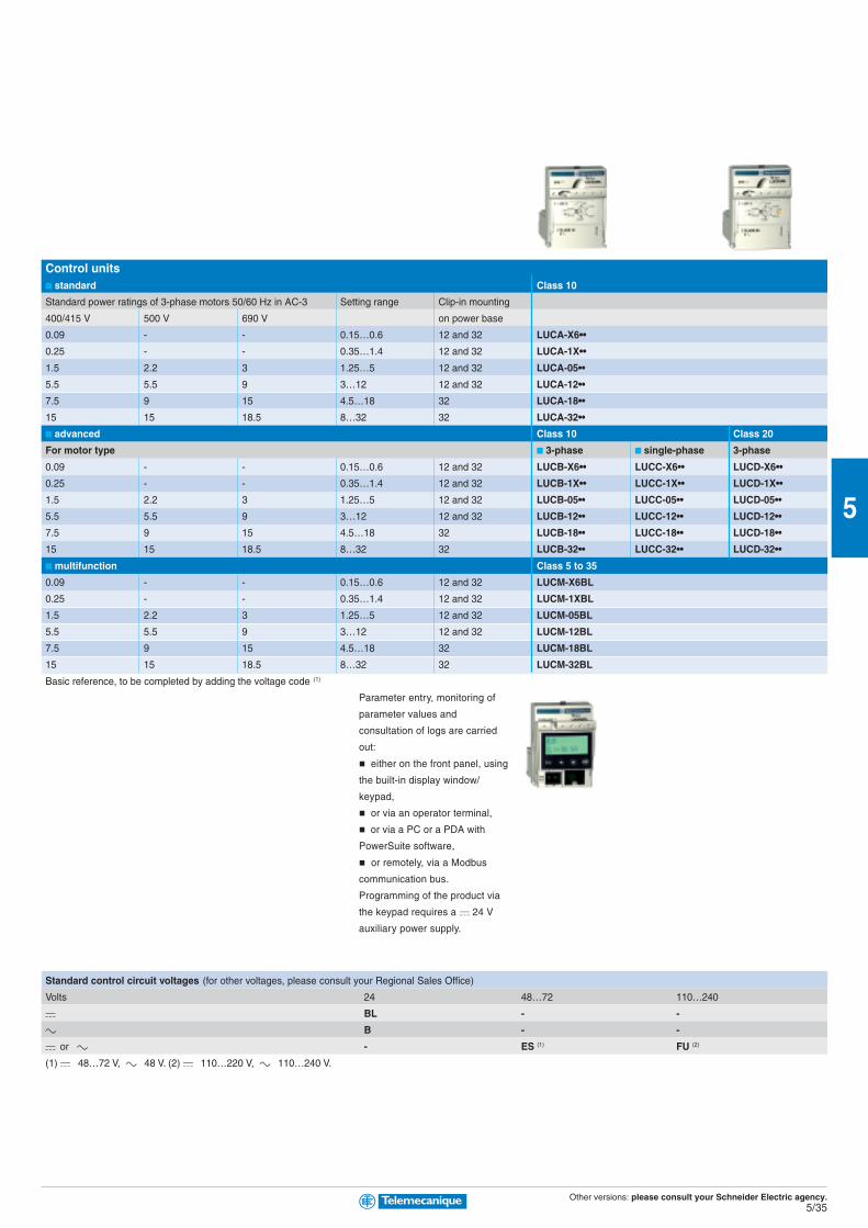
Other versions: please consult your Schneider Electric agency.5/35
5
Standard control circuit voltages (for other voltages, please consult your Regional Sales Office)
Volts 24 48…72 110…240
a BL - -
c B - -
a or c - ES (1) FU (2)
(1) a: 48…72 V, c: 48 V. (2) a: 110…220 V, c: 110…240 V.
Control units standard Class 10
Standard power ratings of 3-phase motors 50/60 Hz in AC-3 Setting range Clip-in mounting
400/415 V 500 V 690 V on power base
0.09 - - 0.15…0.6 12 and 32 LUCA-X6••
0.25 - - 0.35…1.4 12 and 32 LUCA-1X••
1.5 2.2 3 1.25…5 12 and 32 LUCA-05••
5.5 5.5 9 3…12 12 and 32 LUCA-12••
7.5 9 15 4.5…18 32 LUCA-18••
15 15 18.5 8…32 32 LUCA-32••
advanced Class 10 Class 20
For motor type 3-phase single-phase 3-phase
0.09 - - 0.15…0.6 12 and 32 LUCB-X6•• LUCC-X6•• LUCD-X6••
0.25 - - 0.35…1.4 12 and 32 LUCB-1X•• LUCC-1X•• LUCD-1X••
1.5 2.2 3 1.25…5 12 and 32 LUCB-05•• LUCC-05•• LUCD-05••
5.5 5.5 9 3…12 12 and 32 LUCB-12•• LUCC-12•• LUCD-12••
7.5 9 15 4.5…18 32 LUCB-18•• LUCC-18•• LUCD-18••
15 15 18.5 8…32 32 LUCB-32•• LUCC-32•• LUCD-32••
multifunction Class 5 to 35
0.09 - - 0.15…0.6 12 and 32 LUCM-X6BL
0.25 - - 0.35…1.4 12 and 32 LUCM-1XBL
1.5 2.2 3 1.25…5 12 and 32 LUCM-05BL
5.5 5.5 9 3…12 12 and 32 LUCM-12BL
7.5 9 15 4.5…18 32 LUCM-18BL
15 15 18.5 8…32 32 LUCM-32BL
Basic reference, to be completed by adding the voltage code (1)
Parameter entry, monitoring of
parameter values and
consultation of logs are carried
out:
either on the front panel, using
the built-in display window/
keypad,
or via an operator terminal,
or via a PC or a PDA with
PowerSuite software,
or remotely, via a Modbus
communication bus.
Programming of the product via
the keypad requires a a 24 V
auxiliary power supply.
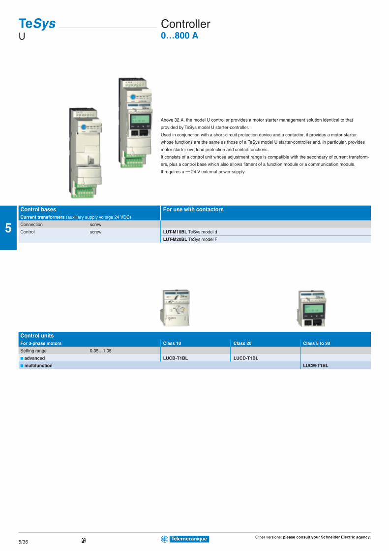
Other versions: please consult your Schneider Electric agency.5/36
5
Above 32 A, the model U controller provides a motor starter management solution identical to that
provided by TeSys model U starter-controller.
Used in conjunction with a short-circuit protection device and a contactor, it provides a motor starter
whose functions are the same as those of a TeSys model U starter-controller and, in particular, provides
motor starter overload protection and control functions.
It consists of a control unit whose adjustment range is compatible with the secondary of current transform-
ers, plus a control base which also allows fitment of a function module or a communication module.
It requires a a 24 V external power supply.
Control bases For use with contactorsCurrent transformers (auxiliary supply voltage 24 VDC)
Connection screw
Control screw LUT-M10BL TeSys model d
LUT-M20BL TeSys model F
Control unitsFor 3-phase motors Class 10 Class 20 Class 5 to 30
Setting range 0.35…1.05
advanced LUCB-T1BL LUCD-T1BL
multifunction LUCM-T1BL
TeSysU
Controller0…800 A
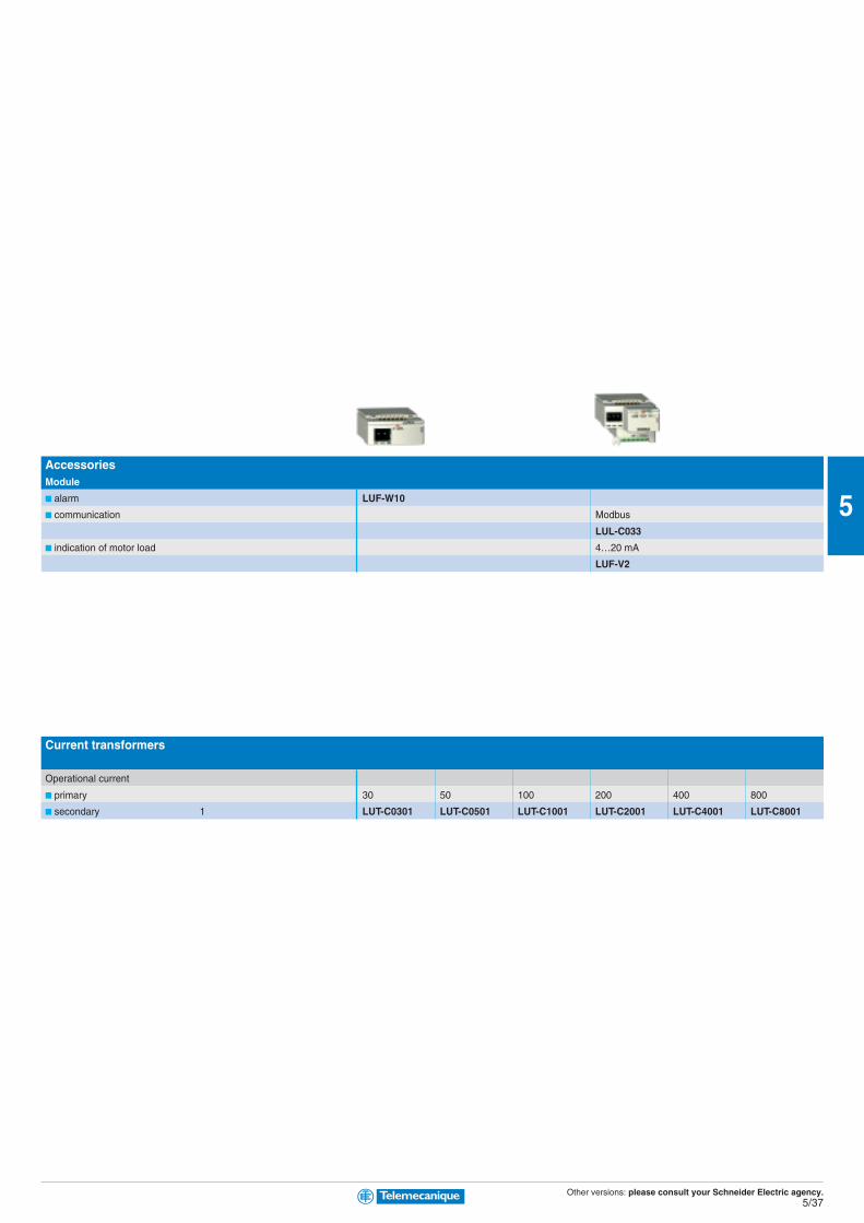
Other versions: please consult your Schneider Electric agency.5/37
5
Current transformers
Operational current
primary 30 50 100 200 400 800
secondary 1 LUT-C0301 LUT-C0501 LUT-C1001 LUT-C2001 LUT-C4001 LUT-C8001
AccessoriesModule
alarm LUF-W10
communication Modbus
LUL-C033
indication of motor load 4…20 mA
LUF-V2
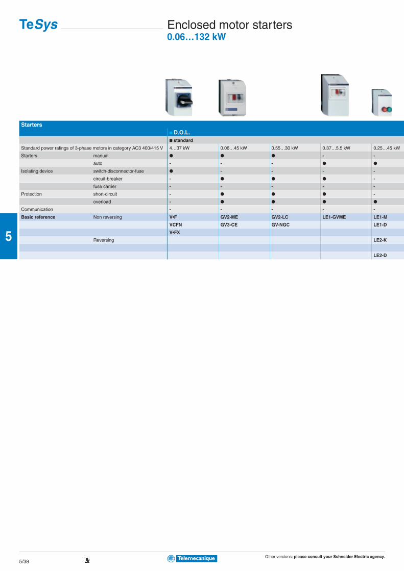
Other versions: please consult your Schneider Electric agency.5/38
5
Starters D.O.L. standard
Standard power ratings of 3-phase motors in category AC3 400/415 V 4…37 kW 0.06…45 kW 0.55…30 kW 0.37…5.5 kW 0.25…45 kW
Starters manual - -
auto - - -
Isolating device switch-disconnector-fuse - - - -
circuit-breaker - -
fuse carrier - - - - -
Protection short-circuit - -
overload -
Communication - - - - -
Basic reference Non reversing V•F GV2-ME GV2-LC LE1-GVME LE1-M
VCFN GV3-CE GV-NGC LE1-D
V•FX
Reversing LE2-K
LE2-D
TeSys Enclosed motor starters0.06…132 kW

Other versions: please consult your Schneider Electric agency.5/39
5
2 stage safety applications AS-i bus standard star-delta
2.2…45 kW 0.06…11 kW 0.06…9 kW 0.06…9 kW 0.06…5.5 kW 5.5…132 kW 7.5…75 kW
- - - - - -
-
- - - - - -
- - -
- - - - -
-
- - - - - -
LE4-K GV2-ME LG1-K LG7-K LF1-M LE3-K LE6-D
LE4-D LG1-D LG7-D LF1-P LE3-D LE3-D
LJ7-K LF7-P LE3-F
LE8-K LG8-K LF2-M
LE8-D LJ8-K LF2-P
LE2-D LF8-P
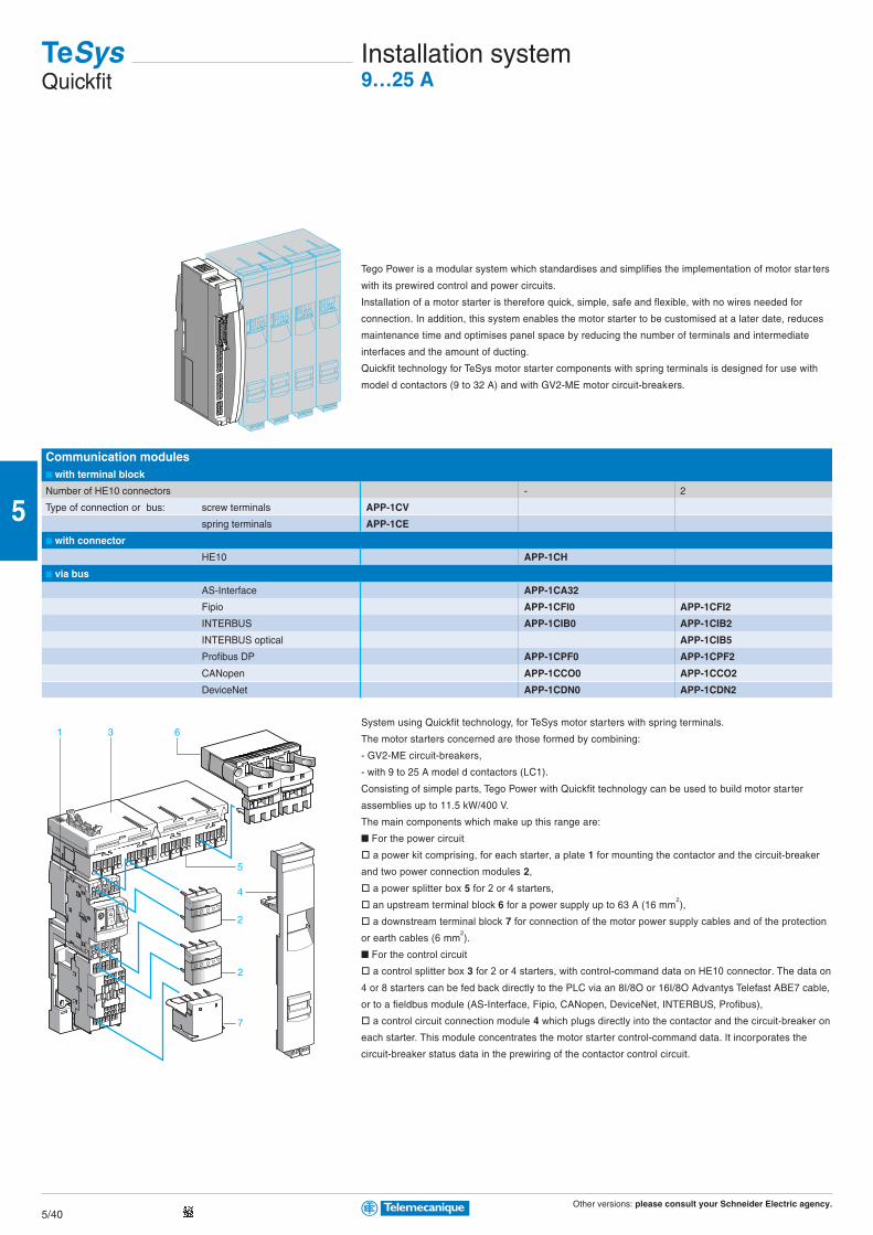
Other versions: please consult your Schneider Electric agency.5/40
5
7
2
2
5
4
1 63
Communication modules with terminal block
Number of HE10 connectors - 2
Type of connection or bus: screw terminals APP-1CV
spring terminals APP-1CE
with connector
HE10 APP-1CH
via bus
AS-Interface APP-1CA32
Fipio APP-1CFI0 APP-1CFI2
INTERBUS APP-1CIB0 APP-1CIB2
INTERBUS optical APP-1CIB5
Profibus DP APP-1CPF0 APP-1CPF2
CANopen APP-1CCO0 APP-1CCO2
DeviceNet APP-1CDN0 APP-1CDN2
Tego Power is a modular system which standardises and simplifies the implementation of motor star ters
with its prewired control and power circuits.
Installation of a motor starter is therefore quick, simple, safe and flexible, with no wires needed for
connection. In addition, this system enables the motor starter to be customised at a later date, reduces
maintenance time and optimises panel space by reducing the number of terminals and intermediate
interfaces and the amount of ducting.
Quickfit technology for TeSys motor starter components with spring terminals is designed for use with
model d contactors (9 to 32 A) and with GV2-ME motor circuit-breakers.
System using Quickfit technology, for TeSys motor starters with spring terminals.
The motor starters concerned are those formed by combining:
- GV2-ME circuit-breakers,
- with 9 to 25 A model d contactors (LC1).
Consisting of simple parts, Tego Power with Quickfit technology can be used to build motor starter
assemblies up to 11.5 kW/400 V.
The main components which make up this range are:
For the power circuit
a power kit comprising, for each starter, a plate 1 for mounting the contactor and the circuit-breaker
and two power connection modules 2,
a power splitter box 5 for 2 or 4 starters,
an upstream terminal block 6 for a power supply up to 63 A (16 mm2),
a downstream terminal block 7 for connection of the motor power supply cables and of the protection
or earth cables (6 mm2).
For the control circuit
a control splitter box 3 for 2 or 4 starters, with control-command data on HE10 connector. The data on
4 or 8 starters can be fed back directly to the PLC via an 8I/8O or 16I/8O Advantys Telefast ABE7 cable,
or to a fieldbus module (AS-Interface, Fipio, CANopen, DeviceNet, INTERBUS, Profibus),
a control circuit connection module 4 which plugs directly into the contactor and the circuit-breaker on
each starter. This module concentrates the motor starter control-command data. It incorporates the
circuit-breaker status data in the prewiring of the contactor control circuit.
TeSysQuickfit
Installation system9…25 A
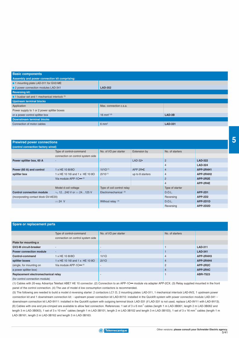
Other versions: please consult your Schneider Electric agency.5/41
5
Basic componentsAssembly and power connection kit comprising:
1 mounting plate LAD-311 for GV2-ME
2 power connection modules LAD-341 LAD-352
Reversing kit:
1 busbar set and 1 mechanical interlock (5)
Upstream terminal blocks
Application Max. connection c.s.a.
Power supply to 1 or 2 power splitter boxes
or a power control splitter box 16 mm2 (6) LAD-3B
Downstream terminal blocks
Connection of motor cables 6 mm2 LAD-331
Prewired power connections(control connection factory wired)
Type of control-command No. of I/O per starter Extension by No. of starters
connection on control system side
Power splitter box, 60 A - - LAD-32• 2 LAD-322
4 LAD-324
Power (60 A) and control 1 x HE 10 8I/8O 1I/1O (1) APP 2R•E 4 APP-2R4H1
splitter box 1 x HE 10 16I and 1 x HE 10 8O 2I/10 (1) up to 8 starters 4 APP-2R4H2
Via module APP-1C••• (2) - 2 APP-2R2E
4 APP-2R4E
Model d coil voltage Type of coil control relay Type of starter
Control connection module c 12…240 V or a 24…125 V Electromechanical (3) D.O.L. APP-2D1
(incorporating contact block GV-AE20) Reversing APP-2D2
a 24 V Without relay (4) D.O.L. APP-2D1D
Reversing APP-2D2D
Spare or replacement parts
Type of control-command No. of I/O per starter No. of starters
connection on control system side
Plate for mounting a
GV2-M circuit-breaker - - 1 LAD-311
Power connection module - - 1 LAD-341
Control-command 1 x HE 10 8I/8O 1I/1O 4 APP-2R4H3
splitter boxes 1 x HE 10 16I and 1 x HE 10 8O 2I/1O 4 APP-2R4H4
(single, for mounting on Via module APP-1C••• (2) - 2 APP-2R2C
a power splitter box) 4 APP-2R4C
Replacement electromechanical relay - 1 ABR-7S23
(for control connection module)
(1) Cables with 20-way Advantys Telefast ABE7 HE 10 connector. (2) Connection to an APP-1C••• module via adapter APP-2CX. (3) Relay supplied mounted in the front
panel of the control connection. (4) The use of model d low consumption contactors is recommended.
(5) The following are needed to build a model d reversing starter: 2 contactors LC1 D, 2 mounting plates LAD-311, 1 mechanical interlock LAD-9V2, 1 upstream power
connection kit and 1 downstream connection kit: - upstream power connection kit LAD-9V10: installed in the Quickfit system with power connection module LAD-341 –
downstream connection kit LAD-9V11: installed in the Quickfit system with outgoing terminal block LAD-331 (if LAD-331 is not used, replace LAD-9V11 with LAD-9V13).
(6) Cables with one end pre-crimped are available to allow fast connection. References: 1 set of 3 x 6 mm2 cables (length 1 m LAD-3B061, length 2 m LAD-3B062 and
length 3 m LAD-3B063), 1 set of 3 x 10 mm2 cables (length 1 m LAD-3B101, length 2 m LAD-3B102 and length 3 m LAD-3B103), 1 set of 3 x 16 mm
2 cables (length 1 m
LAD-3B161, length 2 m LAD-3B162 and length 3 m LAD-3B163.
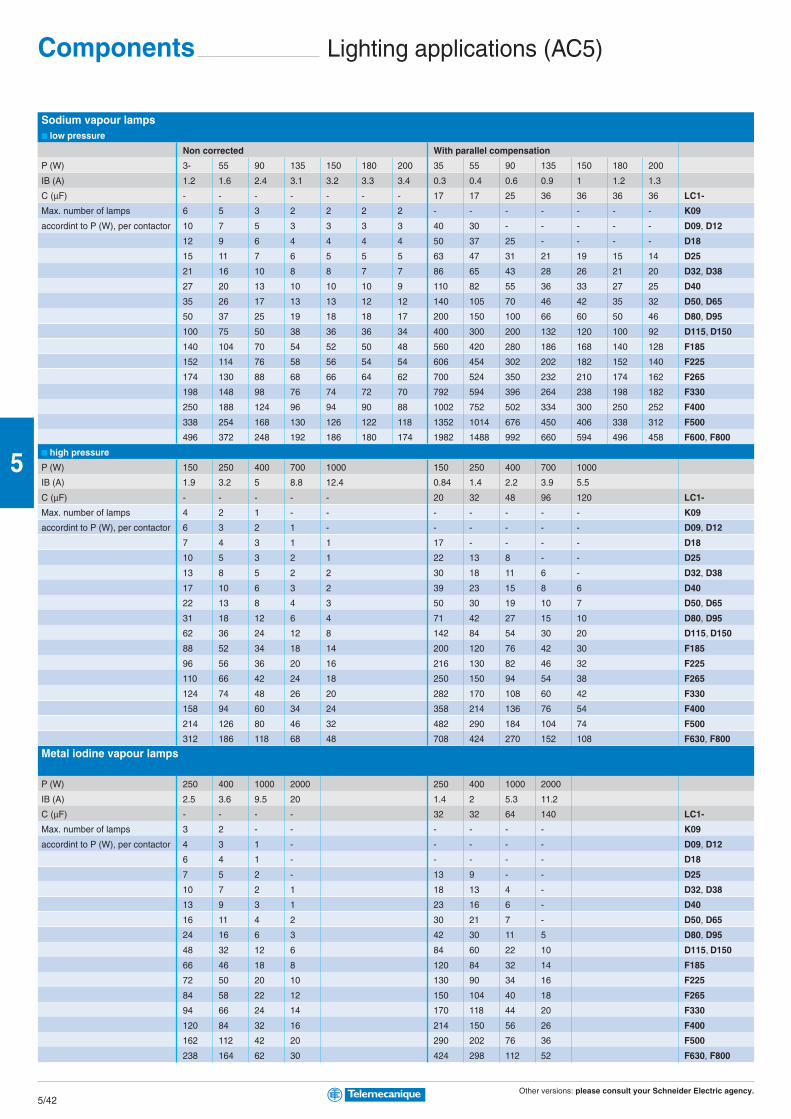
Other versions: please consult your Schneider Electric agency.5/42
5
Sodium vapour lamps low pressure
Non corrected With parallel compensation
P (W) 3- 55 90 135 150 180 200 35 55 90 135 150 180 200
IB (A) 1.2 1.6 2.4 3.1 3.2 3.3 3.4 0.3 0.4 0.6 0.9 1 1.2 1.3
C (µF) - - - - - - - 17 17 25 36 36 36 36 LC1-
Max. number of lamps 6 5 3 2 2 2 2 - - - - - - - K09
accordint to P (W), per contactor 10 7 5 3 3 3 3 40 30 - - - - - D09, D12
12 9 6 4 4 4 4 50 37 25 - - - - D18
15 11 7 6 5 5 5 63 47 31 21 19 15 14 D25
21 16 10 8 8 7 7 86 65 43 28 26 21 20 D32, D38
27 20 13 10 10 10 9 110 82 55 36 33 27 25 D40
35 26 17 13 13 12 12 140 105 70 46 42 35 32 D50, D65
50 37 25 19 18 18 17 200 150 100 66 60 50 46 D80, D95
100 75 50 38 36 36 34 400 300 200 132 120 100 92 D115, D150
140 104 70 54 52 50 48 560 420 280 186 168 140 128 F185
152 114 76 58 56 54 54 606 454 302 202 182 152 140 F225
174 130 88 68 66 64 62 700 524 350 232 210 174 162 F265
198 148 98 76 74 72 70 792 594 396 264 238 198 182 F330
250 188 124 96 94 90 88 1002 752 502 334 300 250 252 F400
338 254 168 130 126 122 118 1352 1014 676 450 406 338 312 F500
496 372 248 192 186 180 174 1982 1488 992 660 594 496 458 F600, F800
high pressure
P (W) 150 250 400 700 1000 150 250 400 700 1000
IB (A) 1.9 3.2 5 8.8 12.4 0.84 1.4 2.2 3.9 5.5
C (µF) - - - - - 20 32 48 96 120 LC1-
Max. number of lamps 4 2 1 - - - - - - - K09
accordint to P (W), per contactor 6 3 2 1 - - - - - - D09, D12
7 4 3 1 1 17 - - - - D18
10 5 3 2 1 22 13 8 - - D25
13 8 5 2 2 30 18 11 6 - D32, D38
17 10 6 3 2 39 23 15 8 6 D40
22 13 8 4 3 50 30 19 10 7 D50, D65
31 18 12 6 4 71 42 27 15 10 D80, D95
62 36 24 12 8 142 84 54 30 20 D115, D150
88 52 34 18 14 200 120 76 42 30 F185
96 56 36 20 16 216 130 82 46 32 F225
110 66 42 24 18 250 150 94 54 38 F265
124 74 48 26 20 282 170 108 60 42 F330
158 94 60 34 24 358 214 136 76 54 F400
214 126 80 46 32 482 290 184 104 74 F500
312 186 118 68 48 708 424 270 152 108 F630, F800
Metal iodine vapour lamps
P (W) 250 400 1000 2000 250 400 1000 2000
IB (A) 2.5 3.6 9.5 20 1.4 2 5.3 11.2
C (µF) - - - - 32 32 64 140 LC1-
Max. number of lamps 3 2 - - - - - - K09
accordint to P (W), per contactor 4 3 1 - - - - - D09, D12
6 4 1 - - - - - D18
7 5 2 - 13 9 - - D25
10 7 2 1 18 13 4 - D32, D38
13 9 3 1 23 16 6 - D40
16 11 4 2 30 21 7 - D50, D65
24 16 6 3 42 30 11 5 D80, D95
48 32 12 6 84 60 22 10 D115, D150
66 46 18 8 120 84 32 14 F185
72 50 20 10 130 90 34 16 F225
84 58 22 12 150 104 40 18 F265
94 66 24 14 170 118 44 20 F330
120 84 32 16 214 150 56 26 F400
162 112 42 20 290 202 76 36 F500
238 164 62 30 424 298 112 52 F630, F800
Components Lighting applications (AC5)

Other versions: please consult your Schneider Electric agency.5/43
5
Incandescent and halogen lamps
P (W) 60 75 100 150 200 300 500 750 1000
IB (A) 0.27 0.34 0.45 0.68 0.91 1.40 2.30 3.40 4.60 LC1-
Max. number of lamps 35 28 21 14 10 6 4 2 2 K09
accordint to P (W), per contactor 59 47 35 23 17 11 7 4 3 D09, D12
77 61 46 30 23 15 9 6 4 D18
92 73 55 36 27 18 11 7 5 D25
129 103 77 51 38 25 15 10 7 D32, D38
163 129 97 64 48 31 19 13 9 D40
207 164 124 82 62 40 24 16 12 D50, D65
296 235 177 117 88 57 34 23 17 D80, D95
430 340 256 170 126 82 50 34 24 D115
466 370 280 184 138 90 54 36 26 D150
710 564 426 282 210 136 82 56 40 F185
770 610 462 304 228 148 90 60 44 F225
888 704 532 352 262 170 104 70 52 F265
1006 800 604 400 298 194 118 80 58 F330
1274 1010 764 504 378 244 148 100 74 F400
1718 1364 1030 682 508 330 200 136 100 F500
2328 1850 1396 924 690 448 272 184 136 F600
2776 2204 1666 1102 824 534 326 220 162 F800
Fluorescent lamps with starter single fitting
Non-corrected With parallel correction
P (W) 20 40 65 80 110 20 40 65 80 110
IB (A) 0.39 0.45 0.70 0.80 1.2 0.17 0.26 0.42 0.52 0.72
C (µF) - - - - - 5 5 7 7 16 LC1-
Max. number of lamps 24 21 13 12 8 56 36 22 18 - K09
accordint to P (W), per contactor 41 35 22 20 13 94 61 38 30 22 D09, D12
53 46 30 26 17 123 80 50 40 29 D18
66 57 37 32 21 152 100 61 50 36 D25
89 77 50 43 29 205 134 83 67 48 D32, D38
112 97 62 55 36 258 169 104 84 61 D40
143 124 80 70 46 329 215 133 107 77 D50, D65
205 177 114 100 66 470 367 190 153 111 D80, D95
410 354 228 200 132 940 614 380 306 222 D115, D150
492 426 274 240 160 1128 738 456 368 266 F185
532 462 296 260 172 1224 800 490 400 288 F225
614 532 342 300 200 1412 922 570 462 332 F265
696 604 388 340 226 1600 1046 648 522 378 F330
882 764 490 430 286 2024 1322 818 662 478 F400
1190 1030 662 580 386 2728 1724 1104 892 644 F500
1612 1398 698 786 524 3700 2418 1498 1210 874 F630, F800
twin fitting
P (W) 2x20 2x40 2x65 2x80 2x110 2x20 2x40 2x65 2x80 2x110
IB (A) 2x0.22 2x0.41 2x0.67 2x0.82 2x1.1 2x0.13 2x0.24 2x0.39 2x0.48 2x0.65 LC1-
Max. number of lamps 2x21 2x11 2x7 2x5 2x4 2x36 2x20 2x12 2x10 2x7 K09
accordint to P (W), per contactor 2x36 2x18 2x10 2x8 2x6 2x60 2x32 2x20 2x16 2x12 D09, D12
2x46 2x24 2x14 2x12 2x8 2x80 2x42 2x26 2x20 2x16 D18
2x58 2x30 2x18 2x14 2x10 2x100 2x54 2x32 2x26 2x20 D25
2x78 2x42 2x26 2x20 2x14 2x134 2x72 2x44 2x36 2x26 D32, D38
2x100 2x52 2x32 2x26 2x18 2x168 2x90 2x56 2x44 2x32 D40
2x126 2x68 2x40 2x34 2x24 2x214 2x116 2x70 2x58 2x42 D50, D65
2x180 2x96 2x58 2x48 2x36 2x306 2x166 2x10² 2x82 2x60 D80, D95
2x360 2x194 2x118 2x96 2x72 2x614 2x332 2x204 2x166 2x122 D115, D150
2x436 2x234 2x142 2x116 2x86 2x738 2x400 2x246 2x200 2x148 F185
2x472 2x254 2x154 2x126 2x94 2x800 2x432 2x266 2x216 2x160 F225
2x544 2x292 2x178 2x146 2x10⁸ 2x922 2x500 2x308 2x250 2x184 F265
2x618 2x332 2x202 2x166 2x124 2x1046 2x566 2x348 2x282 2x208 F330
2x782 2x420 2x256 2x210 2x156 2x1322 2x716 2x440 2x358 2x264 F400
2x1054 2x566 2x346 2x282 2x210 2x1784 2x966 2x594 2x482 2x356 F500
2x1430 2x766 2x468 2x384 2x286 2x2418 2x1310 2x806 2x654 2x484 F630, F800

Other versions: please consult your Schneider Electric agency.5/44
5
On-load capacitor switchingfor bar-mounted contactors, a.c. control circuit
Without damping resistor With damping resistor
Rated operational voltage (V) Number of poles Max. operational Basic reference, Number of poles Max. operational Basic reference,
current (A) to be completed current (A) to be completed
50 Hz 180 Hz 50 Hz 180 Hz
1300 1 80 60 CE5-FB11•11 1 + 1 staggered pole 80 60 CE6-FB12•11
160 125 CE5-GB11•11 160 125 CE6-GB12•11
240 190 CE5-HB11•11 240 190 CE6-HB12•11
2 80x2 60x2 CE5-FB21•11
160x2 125x2 CE5-GB21•11
240x2 190x2 CE5-HB21•11 2 + 2 staggered poles 240x2 190x2 CE6-HB22•11
3 80x3 60x3 CE5-FB31•11
160x3 125x3 CE5-GB31•11
240x3 190x3 CE5-HB31•11
1500 2 poles in series 160 125 CE5-GB12•11 1 + 2 staggered poles 160 125 CE6-GB13•11
280 220 CE5-HB12•11 280 220 CE6-HB13•11
2 x 2 poles in series 280x2 220x2 CE5-HB22•11
2000 2 poles in series 240 190 CS5-HB12•11 1 + 2 staggered poles 240 190 CS6-HB13•11
2 x 2 poles in series 240x2 190x2 CS5-HB22•11
3000 3 poles in series 280 220 CS5-HB13•11 1 + 3 staggered poles 280 220 CS6-HB14•11
Components Capacitor switching0…1000 kVAR
Standard control circuit voltagesaaaaa supply
Volts 110 125 127 200 220 240 250 380 415 440 500
50 Hz (coil LX1) F - G L M U - Q N R S

Other versions: please consult your Schneider Electric agency.5/45
5
Maximum operational power of contactors standard contactors
Operational power at 50/60 Hz
θ ≥ 40 °C θ ≥ 55 °C Peak current Contactor
220 V 400 V 600 V 220 V 400 V 600 V size
240 V 440 V 690 V 240 V 440 V 690 V
kVAR kVAR kVAR kVAR kVAR kVAR A
6 11 15 6 11 15 560 LC1-D09, D12
9 15 20 9 15 20 850 LC1-D18
11 20 25 11 20 25 1600 LC1-D25
14 25 30 14 25 30 1900 LC1-D32, D38
17 30 37 17 30 37 2160 LC1-D40
22 40 50 22 40 50 2160 LC1-D50
22 40 50 22 40 50 3040 LC1-D65
35 60 75 35 60 75 3040 LC1-D80, D95
50 90 125 38 75 80 3100 LC1-D115
60 110 135 40 85 90 3300 LC1-D150
70 125 160 50 100 100 3500 LC1-F185
80 140 190 60 110 110 4000 LC1-F225
90 160 225 75 125 125 5000 LC1-F265
100 190 275 85 140 165 6500 LC1-F330
125 220 300 100 160 200 8000 LC1-F400
180 300 400 125 220 300 10000 LC1-F500
250 400 600 190 350 500 12000 LC1-F630
250 400 600 190 350 500 14200 LC1-F800
200 350 500 180 350 500 25000 LC1-BL
300 550 650 250 500 600 25000 LC1-BM
500 8350 950 400 750 750 25000 LC1-BP
600 1100 1300 500 1000 1000 25000 LC1-BR
special contactors
Operational power at 50/60 Hz
θ ≥ 55 °C Instantaneous auxiliary contacts Tightening torque on cable end Basic reference,
220 V 400 V 660 V to be completed
240 V 440 V 690 V
kVAR kVAR kVAR N/O N/C N.m
6.7 12.5 18 1 1 1.2 LC1-DFK11••
- 2 1.2 LC1-DFK02••
8.5 16.7 24 1 1 1.7 LC1-DGK11••
- 2 1.7 LC1-DGK02••
10 20 30 1 1 1.9 LC1-DLK11••
- 2 1.9 LC1-DLK02••
15 25 36 1 1 2.5 LC1-DMK11••
- 2 2.5 LC1-DMK02••
20 33.3 48 1 2 5 LC1-DPK12••
25 40 58 1 2 5 LC1-DTK12••
40 60 92 1 2 9 LC1-DWK12••
Standard control circuit voltagesaaaaa supply
Volts 24 42 48 110 115 220 230 240 380 400 415 440
50/60 Hz (coil LX1) B7 D7 E7 F7 FE7 M7 P7 U7 Q7 V7 N7 R7

Other versions: please consult your Schneider Electric agency.5/46
5
Maximum operational current (device in open air)
Contactors LC1-/LP1- LC1-/LP1- LC1- LC1- LC1- LC1- LC1- LC1- LC1- LC1-
3-pole K09 K12 D09 D12 D18 D25 D32 D38 D40
4-pole DT20 DT25 DT32 DT40
LC2- changeover contactor pairs, factory assembled K09004 K12004 DT20 DT25 DT32 DT40 D40004
Operational current in AC-1, in A, ≥ 40° C A 20 20 25 20 25 32 40 50 50 60
according to ambient temperature ≥ 60° C A 20 20 25 20 25 32 40 50 50 60
≥ 70° CMaximum operational 220/230 V kW 8 8 9 8 9 11 14 18 18 21
power ≤ 60° C 240 V kW 8 8 9 8 9 12 15 19 19 23
380/400 V kW 14 14 15 14 15 20 25 31 31 37
415 V kW 14 14 17 14 17 21 27 34 34 41
440 V kW 15 15 18 15 18 23 29 36 36 43
500 V kW 17 17 20 17 20 23 33 41 41 49
660/690 V kW 22 22 27 22 27 34 43 54 54 65
Increase in operational currentby parallel connection of polesApply the following coefficients to the currents or powers above;these coefficients take into account an often unbalanced distributionof current between the poles: 2 poles in parallel K = 1.6 3 poles in parallel K = 2.25 4 poles in parallel K = 2.8
Connection accessories for heating applications
Paralleling links for: Reference
model k 2 poles with screw clamp terminals LA9-E01
4 poles with screw clamp terminals LA9-E02
model d 2 poles D09…D38 LA9-D2561
DT20 and DT25 (4P) LA9-D1261
DT32…DT40 (4P) LAD-D96061
D40…D65 LA9-D40961
D80 LA9-D80961
3 poles D09…D38 LAD-9P3 (1)
D80 LA9-D80962
4 poles DT20…DT25 LA9-D1263
D40…D65 LA9-D40963
D80 LA9-D80963
model F 2 to 2 LC1-F1154 LA9-FF602
LC1-F1504, F1854 LA9-FG602
LC1-F2254, F2654, F3304, F4004 LA9-FH602
LC1-F5004 LA9-FK602
LC1-F6304 LA9-FL602
(1) Link that can be split, allowing parallel connection of 2 poles
Heating applications and changeovercontactor pairs0…2750 A
Components
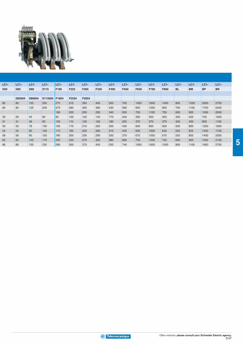
Other versions: please consult your Schneider Electric agency.5/47
5
LC1- LC1- LC1- LC1- LC1- LC1- LC1- LC1- LC1- LC1- LC1- LC1- LC1- LC1- LC1- LC1- LC1-
D50 D65 D80 D115 F185 F225 F265 F330 F400 F500 F630 F780 F800 BL BM BP BR
D65004 D80004 D115004 F1854 F2254 F2654
80 80 125 250 275 315 350 400 500 700 1000 1600 1000 800 1250 2000 2750
80 80 125 200 275 280 300 360 430 580 850 1350 850 700 1100 1750 2400
180 200 250 290 340 500 700 1100 700 600 900 1500 2000
29 29 45 80 90 100 120 145 170 240 350 550 350 300 425 700 1000
31 31 49 83 100 110 125 160 180 255 370 570 370 330 450 800 1100
50 50 78 135 165 175 210 250 300 430 600 950 600 500 800 1200 1600
54 54 85 140 170 185 220 260 310 445 630 1000 630 525 825 1250 1700
58 58 90 150 180 200 230 290 330 370 670 1050 670 550 850 1400 2000
65 65 102 170 200 220 270 320 380 660 750 1200 750 600 900 1500 2100
86 86 135 235 280 300 370 400 530 740 1000 1650 1000 800 1100 1900 2700

Other versions: please consult your Schneider Electric agency.5/48
5
Mounting accessories for changeover contactor pairs(for customer assembly)
Contactor type Set of power connections Mechanical Contactor type Set of power connections Mechanical
interlock interlock
2 contactors, vertically mounted
4-pole changeover pairs with locking device components
LC1-B EZ2-LB0601
2 identical contactors, horizontally mounted
with electrical interlocking kit for the contactors
LC1-DT20…DT40 LAD-T9R1V (1)
mechanical interlock with integral electrical interlocking
LC1-D65004 LA9-D6570 LA9-D4002 LC1-D80004 LA9-D8070 LA9-D4002
LP1-D80004 LA9-D8070 LA9-D8002 LC1-D115004 LA9-D11570 LA9-D11502
without electrical interlocking (2)
LC1-DT20…DT32 LAD-T9R1 (2) LC1-DT40 and DT60 LAD-T9R2 (2)
LC1 or LP1-D65004 LA9-D6570 LA9-D50978 LC1-D80004 LA9-D8070 LA9-D50978
LP1-D80004 LA9-D8070 LA9-D80978
2 contactors of identical rating, horizontally mounted
4-pole changeover pairs
LC1-F1154 LA9-FF977 LA9-FF970 LC1-F1504 LA9-F15077 LA9-FF970
LC1-F1854 LA9-FG977 LA9-FG970 LC1-F2254 LA9-F22577 LA9-FG970
LC1-F2654 LA9-FH977 LA9-FJ970 LC1-F3304 LA9-FJ977 LA9-FJ970
LC1-F4004 LA9-FJ977 LA9-FJ970 LC1-F5004 LA9-FK977 LA9-FJ970
LC1-F6304 LA9-FL977 LA9-FL970
3-pole changeover pairs with electrical interlocking
LC1-D115 and D150 LA9-D11571 LA9-D11502
reversers assembled using 2 contactors, vertically mounted
4-pole changeover pairs using contactors of identical rating (3) 3 or 4-pole changeover pairs using contactors of different rating
At bottom At top
LC1-F1154 or F1505 (3) LA9-FF4F LC1-F115 or F1154 LC1-F185 or F1854 LA9-FG4F
LC1-F1854 (3) LA9-FG4G or LC1-F150 or F1504 LC1-F225 or F2254 LA9-FG4F
LC1-F2254 (3) LA9-FG4G LC1-F265 or F2654 LA9-FH4F
LC1-F2654 or F3304 (3) LA9-FH4H LC1-F300 or F3304 LA9-FH4F
LC1-F4004 (3) LA9-FJ4J LC1-F400 or F4004 LA9-FJ4F
LC1-F5004 (3) LA9-FK4K LC1-F500 or F5004 LA9-FK4F
LC1-F6304 (3) LA9-FL4L LC1-F630, F6304 or F800 LA9-FL4F
LC1-F7804 (4) LA9-FX971 (4) LC1-F185 or F1854 LC1-F265 or F2654 LA9-FH4G
or LC1-F225 or F2254 LC1-F330 or F3304 LA9-FH4G
LC1-F400 or F4004 LA9-FJ4G
LC1-F500 or F5004 LA9-FK4G
LC1-F630, F6304 or F800 LA9-FL4G
LC1-F265 or F2654 LC1-F400 or F4004 LA9-FJ4H
or LC1-F330 or F3304 LC1-F500 or F5004 LA9-FK4H
LC1-F630, F6304 or F800 LA9-FL4H
LC1-F400 or F4004 LC1-F500 or F5004 LA9-FK4J
LC1-F630, F6304 or F800 LA9-FL4J
LC1-F500 or F5004 LC1-F630, F6304 or F800 LA9-FL4K
(1) Including mechanical interlock, (2) Order separately 2 auxiliary contact blocks LAD-N•1 to obtain electrical interlocking between the two contactors, (3) Power connections to
be made by the customer. (4) Double mechanical interlock mechanism with 2 interlock connecting rods and 4 power connecting links.
Accessories for changeover contactor pairs0…2750 A
Components

Other versions: please consult your Schneider Electric agency.5/49
5
TeSys Notes
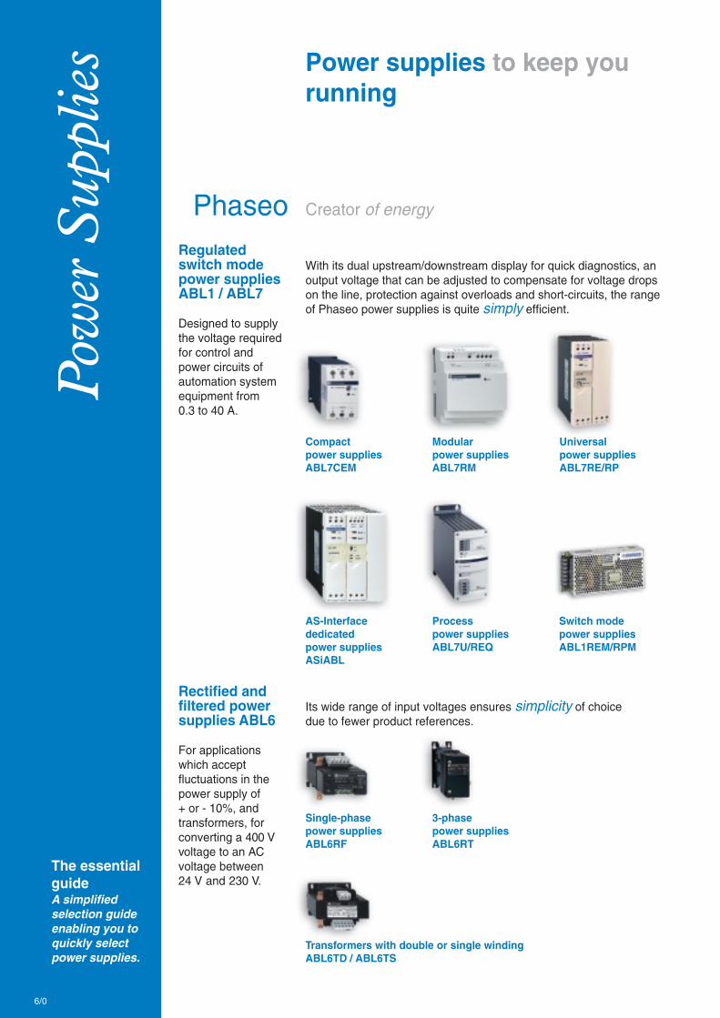
Pow
er S
uppl
ies
Creator of energy
The essentialguideA simplifiedselection guideenabling you toquickly selectpower supplies.
Power supplies to keep yourunning
PhaseoRegulatedswitch modepower suppliesABL1 / ABL7
Designed to supplythe voltage requiredfor control andpower circuits ofautomation systemequipment from0.3 to 40 A.
With its dual upstream/downstream display for quick diagnostics, anoutput voltage that can be adjusted to compensate for voltage dropson the line, protection against overloads and short-circuits, the rangeof Phaseo power supplies is quite simply efficient.
Compactpower suppliesABL7CEM
Modularpower suppliesABL7RM
Universalpower suppliesABL7RE/RP
AS-Interfacededicatedpower suppliesASiABL
Processpower suppliesABL7U/REQ
Rectified andfiltered powersupplies ABL6
For applicationswhich acceptfluctuations in thepower supply of+ or - 10%, andtransformers, forconverting a 400 Vvoltage to an ACvoltage between24 V and 230 V.
Its wide range of input voltages ensures simplicity of choicedue to fewer product references.
Single-phasepower suppliesABL6RF
3-phasepower suppliesABL6RT
Transformers with double or single windingABL6TD / ABL6TS
Switch modepower suppliesABL1REM/RPM
6/0

> Switch mode power supplies Phaseo ABL1b Power supplies for single-phase 110…230 Vdedicated automation systemsb Regulated single-phase 12 and 24 V DCb Wide offer: power 60 to 240 Wb Anti harmonic filterb Certification: UL and CSA
> Switch mode power suppliesPhaseo ABL7b Compact, modular and universal powersupplies for single-phase 100 - 240 V applicationsb 2-phase/3-phase 380 - 520 V process powersuppliesb Dual LED displayb Guaranteed output voltageb Wide voltage rangeb Book formatb Conformity to UL/CSA standards
> Rectified and filtered power suppliesPhaseo ABL6Rb Fixed upstream and downstream voltage,power supplies for connection to single-phaseand 3-phase mains supplies.Used to supply all machines and processeswhere a precise 24 V DC is not necessary.b Single-phase power supply:1 > 40 A - 24 > 960 Wb 3-phase power supply:1 > 40 A - 24 > 960 W
> Transformers: Phaseo ABL6Tb Primary voltage: single-phase a 230 - 400 V AC+/– 15 Vb Safety and circuit isolation transformers withnominal power ratings between 25 and 2500 VA
6/1
6
Contents
b Power supplies for control circuitsPhaseo ABL7, ABL1, ABL6 ............................................... 6/2 to 6/4
b TransformersPhaseo ABL6 ................................................................................ 6/5
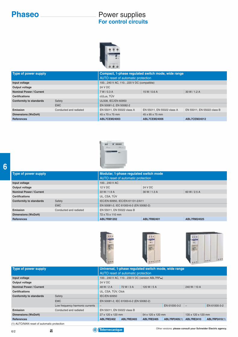
Other versions: please consult your Schneider Electric agency.6/2
6
Power suppliesFor control circuits
Type of power supply Compact, 1-phase regulated switch mode, wide rangeAUTO reset of automatic protection
Input voltage 100…240 V AC, 110…220 V DC (compatible)
Output voltage 24 V DC
Nominal Power / Current 7 W / 0.3 A 15 W / 0.6 A 30 W / 1.2 A
Certifications cULus, TÜV
Conformity to standards Safety UL508, IEC/EN 60950
EMC EN 50081-2, EN 50082-2
Emission Conducted and radiated EN 55011, EN 55022 class A EN 55011, EN 55022 class A EN 55011, EN 55022 class B
Dimensions (WxDxH) 45 x 70 x 75 mm 45 x 95 x 75 mm
References ABL7CEM24003 ABL7CEM24006 ABL7CEM24012
Type of power supply Modular, 1-phase regulated switch modeAUTO reset of automatic protection
Input voltage 100…240 V AC
Output voltage 12 V DC 24 V DC
Nominal Power / Current 22 W / 1.9 A 30 W / 1.3 A 60 W / 2.5 A
Certifications UL, CSA, TÜV
Conformity to standards Safety IEC/EN 60950, IEC/EN 61131-2/A11
EMC EN 50081-2, IEC 61000-6-2 (EN 50082-2)
Emission Conducted and radiated EN 55011, EN 55022 class B
Dimensions (WxDxH) 72 x 70 x 110 mm
References ABL7RM1202 ABL7RM2401 ABL7RM24025
Type of power supply Universal, 1-phase regulated switch mode, wide rangeAUTO reset of automatic protection
Input voltage 100…240 V AC, 110…230 V DC (version ABL7RP••)
Output voltage 24 V DC
Nominal Power / Current 48 W / 2 A 72 W / 3 A 120 W / 5 A 240 W / 10 A
Certifications UL, CSA, TÜV, Ctick
Conformity to standards Safety IEC/EN 60950
EMC EN 50081-2, IEC 61000-6-2 (EN 50082-2)
Low frequency harmonic currents – EN 61000-3-2 – EN 61000-3-2
Emission Conducted and radiated EN 55011, EN 55022 class B
Dimensions (WxDxH) 27 x 120 x 120 mm 54 x 120 x 120 mm 135 x 120 x 120 mm
References ABL7RE2402 ABL7RE2403 ABL7RE2405 ABL7RP2405(1) ABL7RE2410 ABL7RP2410(1)
(1) AUTO/MAN reset of automatic protection
Phaseo
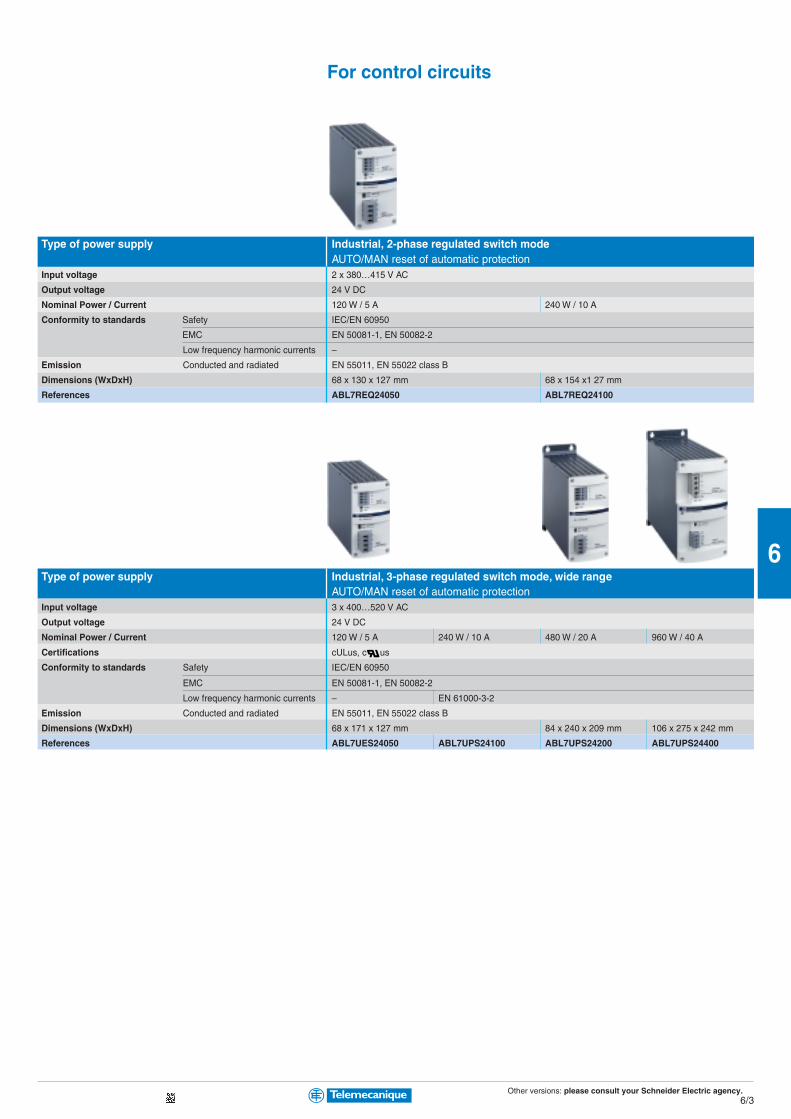
Other versions: please consult your Schneider Electric agency.6/3
6
For control circuits
Type of power supply Industrial, 2-phase regulated switch modeAUTO/MAN reset of automatic protection
Input voltage 2 x 380…415 V AC
Output voltage 24 V DC
Nominal Power / Current 120 W / 5 A 240 W / 10 A
Conformity to standards Safety IEC/EN 60950
EMC EN 50081-1, EN 50082-2
Low frequency harmonic currents –
Emission Conducted and radiated EN 55011, EN 55022 class B
Dimensions (WxDxH) 68 x 130 x 127 mm 68 x 154 x1 27 mm
References ABL7REQ24050 ABL7REQ24100
Type of power supply Industrial, 3-phase regulated switch mode, wide rangeAUTO/MAN reset of automatic protection
Input voltage 3 x 400…520 V AC
Output voltage 24 V DC
Nominal Power / Current 120 W / 5 A 240 W / 10 A 480 W / 20 A 960 W / 40 A
Certifications cULus, c us
Conformity to standards Safety IEC/EN 60950
EMC EN 50081-1, EN 50082-2
Low frequency harmonic currents – EN 61000-3-2
Emission Conducted and radiated EN 55011, EN 55022 class B
Dimensions (WxDxH) 68 x 171 x 127 mm 84 x 240 x 209 mm 106 x 275 x 242 mm
References ABL7UES24050 ABL7UPS24100 ABL7UPS24200 ABL7UPS24400

Other versions: please consult your Schneider Electric agency.6/4
6
Power suppliesFor control circuits
Type of power supply Industrial, regulated switch mode
Input voltage 85 V…264 V AC 85 V…132 V AC / 170 V…264 V AC
Output voltage 12 V DC 24 V DC 24 V DC
Nominal Power / Current 60 W / 5 A 100 W / 8.3 A 60 W / 2.5 A 100 W / 4.2 A 150 W / 6.2 A 240 W / 10 A
Certifications UL, c CSA us, CE, Ctick
Conformity to standards Safety IEC/EN 60950-1, SELV
EMC EN 55011/55022 cIB, IEC/EN 61000-6-2/3, IEC/EN 61000--4-2, 43, 4, 5, 6, 8, 11, 12
Dimensions (WxDxH) 150 x 38 x 98 200 x 38 x 98 150 x 38 x 98 200 x 38 x 98 200 x 50 x 98 200 x 65 x 98
References Without filter ABL1REM12050 – ABL1REM24025 ABL1REM24042 ABL1REM24062 ABL1REM24100
With filter (1) – ABL1RPM12083 – ABL1RPM24042 ABL1RPM24062 ABL1RPM24100
(1) Anti harmonic IEC/EN 61000-3-2
Type of power supply Rectified and filtered
Input voltage 215/230/245 or 385/400/415 V AC (±10%) 1-phase 380/400/420 V AC (±10%) 3-phase
Output voltage 24 V DC
Certifications c us
Nominal power 24 W 60 W 120 W 240 W 360 W 480 W 240 W 480 W 720 W 960 W
Nominal current 1 A 2.5 A 5 A 10 A 15 A 20 A 10 A 20 A 30 A 40 A
Power supply references 1-phase ABL6RF24•• (2) 01 02 05 10 15 20 – – – –
3-phase ABL6RT24•• (2) – – – – – – 10 20 30 40
(2) Complete the reference according to the power and current using the adjacent table (example: ABL6RF2401)
Phaseo

Other versions: please consult your Schneider Electric agency.6/5
6
Type of transformer Safety and isolation
Primary voltage 230/400 V AC (±15%) 1-phase
Secondary Single or double winding (see references below)
Certifications
Nominal power 25 VA 40 VA 63 VA 100 VA 160 VA 250 VA 400 VA 630 VA 1000 VA
References, single winding ABL6TS••• (1)
Secondary voltage 12 V 02J 04J 06J 10J 16J 25J – – –
24 V 02B 04B 06B 10B 16B 25B 40B 63B 100B
115 V 02G 04G 06G 10G 16G 25G 40G 63G 100G
230 V 02U 04U 06U 10U 16U 25U 40U 63U 100U
References, double winding ABL6TD••• (1)
Secondary voltage 24/48 V 02B 04B 06B 10B 16B 25B 40B 63B 100B
115/230 V 02G 04G 06G 10G 16G 25G 40G 63G 100G
(1) Complete the reference according to the power and voltage using the table below (example: ABL6TS02J)
Transformers

Inte
rfac
es a
nd I
/Os
IP20: from the heart of the enclosure…
The essentialguideA simplifiedselection guideenabling you toquickly select allthe productsrequired forinterfacing.
Pre-wired system anddistributed I/O solutions to helpyou put everything together
AdvantysSimple, quick, reliable and powerful It enables quick connection ofinputs/outputs to the operative parts. It eliminates unnecessary cablingby replacing the use of PLC terminals and conventional terminal blocks.It comprises a connection cable and 3 types of connection sub-base.
Pre-wired system
Advantys Telefast ABE7
This open I/O modular system integrationsolution is an I/O platform that also providesa very modular wiring solution and a powersupply management system.Right from the start, you will appreciate itspowerful and intelligent configuration software,its networking capabilities, its ease of setting-upand its wealth of parametering features.
Distributed inputs/outputs
Advantys STB
IP67: …to the heart of the machine,put them to the test…
Pre-wired system
PassivesplitterboxesAdvantysABE9
Distributed inputs/outputs
Compact,they eliminate theneed for long anddifficult cable runs.b 4 or 8 channelversion with M12connections
They enable sensors and actuators to be connected in distributedautomation systems using pre-assembled cables, thus reducing wiringtime and costs whilst, at the same time, increasing the operationalavailability of the installation.
MonoblocsplitterboxesAdvantysFTB
ModularsplitterboxesAdvantysFTM
Simple, robustand configurable.b Wide range of I/Ocombinations (16 I,8 I 8 O, 12 I 4 O,16 I/O configurable)
Powerful, compactand modular.b Up to 256 discreteI/Os per bus module
Also see:b Advantys AS-Interface IP20 and IP67 cabling system
(Chapter 8 “AS-Interface cabling system”)
Open and modular, this optimised blocksolution enables the creation of separate groupsof industrial I/Os, each positioned as near to themachine as possible, that are managed by amaster controller (PLC, PC or variable speeddrive) via a fieldbus or communication network.
Advantys OTB
7/0

b The intelligenceintegrated in AdvantysSTB and its softwareresponds perfectly toyour needs bysimplifying theimplementation of yourautomation systems.
b Simplicity:Plug-in connectorsaccelerate and simplifyinstallation andcommissioning;removable memorycards enable busconfigurations to becopied in a fewseconds.
b Adaptability:The modular andevolutionary design ofthe range, I/Omodules, networkinterfaces and optionsavailable enable you todesign a system suitedto your needs.
b Open:Advantys STB can beinterfaced with themain fieldbuses:CANopen, DeviceNet,Ethernet, Fipio,INTERBUS,Modbus Plus,Profibus DP.
Distributed I/OsolutionAdvantys STB
Contents
Connection
b Terminal blocks AB1 ................................................................... 7/2b Cable ends DZ5/AZ5 .................................................................. 7/3b Cabling accessories XZ for sensors/actuators, IP67(see Chapter 1 “Detection”)
Interfaces and pre-wiredsystem
b IP20 plug-in relays, Zelio Relay(see Chapter 3 “Automation”)b IP20 pre-wired systemAdvantys Telefast ABE7 .............................................................. 7/4b IP20 connection interfaces for TwidoAdvantys Telefast ABE7 .............................................................. 7/6b IP67 passive splitter boxesAdvantys ABE9 ............................................................................ 7/9
Distributed inputs/outputs
b IP20 distributed I/OModicon Momentum with processor(see Chapter 3 “Automation”)b IP20 distributed I/O, optimised blockAdvantys OTB ............................................................................... 7/8b IP67 distributed I/O, optimised blockAdvantys FTB ............................................................................... 7/9b IP20 distributed I/O, modular systemAdvantys STB ................................................................. 7/10 to 7/13b IP67 distributed I/O, modular systemAdvantys FTM ............................................................................. 7/14
AS-Interfacecabling system
b IP20 interfaces Advantys AS-Interface(see Chapter 8 “AS-Interface cabling system”)b IP67 interfaces Advantys AS-Interface(see Chapter 8 “AS-Interface cabling system”)
7/1
7
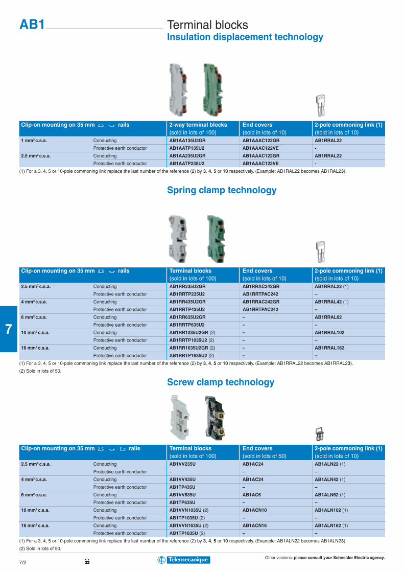
Other versions: please consult your Schneider Electric agency.7/2
7
Terminal blocksInsulation displacement technology
Clip-on mounting on 35 mm rails 2-way terminal blocks End covers 2-pole commoning link (1)(sold in lots of 100) (sold in lots of 10) (sold in lots of 10)
1 mm2 c.s.a. Conducting AB1AA135U2GR AB1AAAC122GR AB1RRAL22
Protective earth conductor AB1AATP135U2 AB1AAAC122VE -
2.5 mm2 c.s.a. Conducting AB1AA235U2GR AB1AAAC122GR AB1RRAL22
Protective earth conductor AB1AATP235U2 AB1AAAC122VE -
(1) For a 3, 4, 5 or 10-pole commoning link replace the last number of the reference (2) by 3, 4, 5 or 10 respectively. (Example: AB1RAL22 becomes AB1RAL23).
Spring clamp technology
Clip-on mounting on 35 mm rails Terminal blocks End covers 2-pole commoning link (1)(sold in lots of 100) (sold in lots of 10) (sold in lots of 10)
2.5 mm2 c.s.a. Conducting AB1RR235U2GR AB1RRAC242GR AB1RRAL22 (1)
Protective earth conductor AB1RRTP235U2 AB1RRTPAC242 –
4 mm2 c.s.a. Conducting AB1RR435U2GR AB1RRAC242GR AB1RRAL42 (1)
Protective earth conductor AB1RRTP435U2 AB1RRTPAC242 –
6 mm2 c.s.a. Conducting AB1RR635U2GR – AB1RRAL62
Protective earth conductor AB1RRTP635U2 – –
10 mm2 c.s.a. Conducting AB1RR1035U2GR (2) – AB1RRAL102
Protective earth conductor AB1RRTP1035U2 (2) – –
16 mm2 c.s.a. Conducting AB1RR1635U2GR (2) – AB1RRAL162
Protective earth conductor AB1RRTP1635U2 (2) – –
(1) For a 3, 4, 5 or 10-pole commoning link replace the last number of the reference (2) by 3, 4, 5 or 10 respectively. (Example: AB1RRAL22 becomes AB1RRAL23).
(2) Sold in lots of 50.
Screw clamp technology
Clip-on mounting on 35 mm rails Terminal blocks End covers 2-pole commoning link (1)(sold in lots of 100) (sold in lots of 50) (sold in lots of 10)
2.5 mm2 c.s.a. Conducting AB1VV235U AB1AC24 AB1ALN22 (1)
Protective earth conductor – – –
4 mm2 c.s.a. Conducting AB1VV435U AB1AC24 AB1ALN42 (1)
Protective earth conductor AB1TP435U – –
6 mm2 c.s.a. Conducting AB1VV635U AB1AC6 AB1ALN62 (1)
Protective earth conductor AB1TP635U – –
10 mm2 c.s.a. Conducting AB1VVN1035U (2) AB1ACN10 AB1ALN102 (1)
Protective earth conductor AB1TP1035U (2) – –
16 mm2 c.s.a. Conducting AB1VVN1635U (2) AB1ACN16 AB1ALN162 (1)
Protective earth conductor AB1TP1635U (2) – –
(1) For a 3, 4, 5 or 10-pole commoning link replace the last number of the reference (2) by 3, 4, 5 or 10 respectively. (Example: AB1ALN22 becomes AB1ALN23).
(2) Sold in lots of 50.
AB1

Other versions: please consult your Schneider Electric agency.7/3
7
Insulated cable endsConforming to DIN 46228 (1)
Type Single cable endsSold in lots of 10 x 100
Packaging Individual or “strings” of bags Dispenser pack Strips of 50 in bag
Conductor c.s.a. 0.5 White DZ5CE005D AZ5CE005D DZ5CEB005D
in mm2 0.75 Grey DZ5CE007D AZ5CE007D DZ5CEB007D
1 Red DZ5CE010D AZ5CE010D DZ5CEB010D
1.5 Black DZ5CE015D AZ5CE015D DZ5CEB015D
2.5 Blue DZ5CE025D AZ5CE025D DZ5CEB025D
Type Double cable endsSold in lots of 5 x 100
Packaging Dispenser pack
Conductor c.s.a. 2 x 0.75 Grey AZ5DE007D
in mm2 2 x 1 Red AZ5DE010D
2 x 1.5 Black AZ5DE015D
2 x 2.5 Blue AZ5DE025D
(1) For insulated cable ends conforming to standard NF C 63-023 , please refer to your Schneider Electric agency.
Cabling accessories
Type Pliers/cutters
Functions Stripping Cutting/stripping Crimping Crimping (ratchet) Cutting/stripping/crimping (2)
For cable c.s.a. 0.08 to 4 mm2 0.4 to 4 mm2 0.5 to 16 mm2 0.25 to 6 mm2 0.5 to 2.5 mm2
References AT1PA7 AT2PE1 AT1PA2 AT2PA5 AT2TRIF01
(2) For use with cable ends packed in strips of 50.
mm2 Øb Øb1 c c1
0.75 2.8 x 5 1.8 15 8
1 3.4 x 5.4 2.05 15 8
1.5 3.6 x 6.6 2.3 15 8
2.5 4.2 x 7.8 2.9 18.5 10
mm2 Øb Øb1 c
0.5 3 1.4 13
0.75 3.1 1.6 13
1 3.4 1.8 13.5
1.5 4 2.1 13.5
2.5 4.6 2.7 14.5
DZ5/AZ5
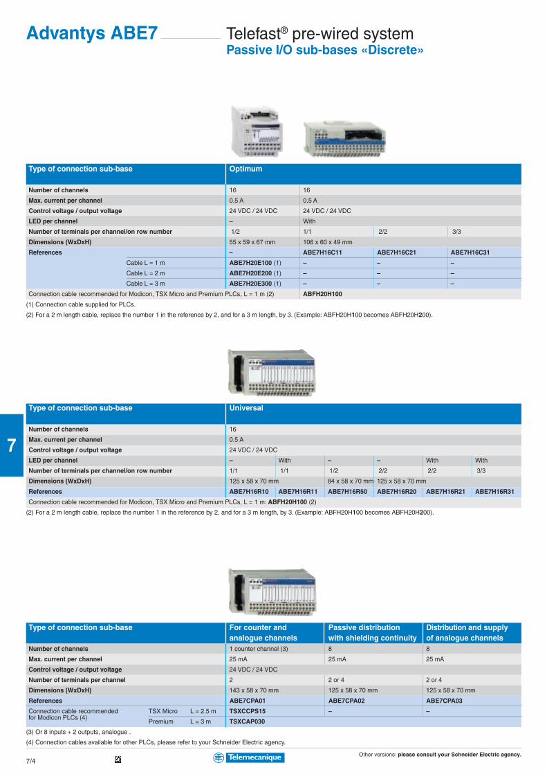
Other versions: please consult your Schneider Electric agency.7/4
7
Telefast® pre-wired systemPassive I/O sub-bases «Discrete»
Type of connection sub-base Optimum
Number of channels 16 16
Max. current per channel 0.5 A 0.5 A
Control voltage / output voltage 24 VDC / 24 VDC 24 VDC / 24 VDC
LED per channel – With
Number of terminals per channel/on row number 1/2 1/1 2/2 3/3
Dimensions (WxDxH) 55 x 59 x 67 mm 106 x 60 x 49 mm
References – ABE7H16C11 ABE7H16C21 ABE7H16C31
Cable L = 1 m ABE7H20E100 (1) – – –
Cable L = 2 m ABE7H20E200 (1) – – –
Cable L = 3 m ABE7H20E300 (1) – – –
Connection cable recommended for Modicon, TSX Micro and Premium PLCs, L = 1 m (2) ABFH20H100
(1) Connection cable supplied for PLCs.
(2) For a 2 m length cable, replace the number 1 in the reference by 2, and for a 3 m length, by 3. (Example: ABFH20H100 becomes ABFH20H200).
Type of connection sub-base Universal
Number of channels 16
Max. current per channel 0.5 A
Control voltage / output voltage 24 VDC / 24 VDC
LED per channel – With – – With With
Number of terminals per channel/on row number 1/1 1/1 1/2 2/2 2/2 3/3
Dimensions (WxDxH) 125 x 58 x 70 mm 84 x 58 x 70 mm 125 x 58 x 70 mm
References ABE7H16R10 ABE7H16R11 ABE7H16R50 ABE7H16R20 ABE7H16R21 ABE7H16R31
Connection cable recommended for Modicon, TSX Micro and Premium PLCs, L = 1 m: ABFH20H100 (2)
(2) For a 2 m length cable, replace the number 1 in the reference by 2, and for a 3 m length, by 3. (Example: ABFH20H100 becomes ABFH20H200).
Type of connection sub-base For counter and Passive distribution Distribution and supplyanalogue channels with shielding continuity of analogue channels
Number of channels 1 counter channel (3) 8 8
Max. current per channel 25 mA 25 mA 25 mA
Control voltage / output voltage 24 VDC / 24 VDC
Number of terminals per channel 2 2 or 4 2 or 4
Dimensions (WxDxH) 143 x 58 x 70 mm 125 x 58 x 70 mm 125 x 58 x 70 mm
References ABE7CPA01 ABE7CPA02 ABE7CPA03
Connection cable recommended TSX Micro L = 2.5 m TSXCCPS15 – –for Modicon PLCs (4)
Premium L = 3 m TSXCAP030
(3) Or 8 inputs + 2 outputs, analogue .
(4) Connection cables available for other PLCs, please refer to your Schneider Electric agency.
Advantys ABE7

Other versions: please consult your Schneider Electric agency.7/5
7
Sockets with plug-in relays and terminals
Type of connection sub-base With soldered solid-state With soldered solid-state With soldered electro-relay inputs relay outputs mechanical relay outputs
Number of channels 16 16 16
Max. current per channel 12 mA 0.5 A 2 A 5 A
Input voltage / output voltage 24 VDC / - 110 VAC / - - / 24 VDC - / 5…30 VDC, 250 VAC
Number of contacts – – 1 N/O
Polarity distribution – – (1) Volt-free
Number of terminals per channel 2
Dimensions (WxDxH) 206 x 58 x 77 mm
References ABE7S16E2B1 ABE7S16E2F0 ABE7S16S2B0(2) ABE7S16S1B2 ABE7R16S111 ABE7R16S210
Connection cable recommended for Modicon, TSX Micro and Premium PLCs, L = 1 m: ABFH20H100 (3)
(1) Contact common per group of 8 channels.
(2) With fault detection signal (can only be used with modules with protected outputs).
(3) For a 2 m length cable, replace the number 1 in the reference by 2, and for a 3 m length, by 3. (Example: ABFH20H100 becomes ABFH20H200).
Type of connection sub-base With plug-in electromechanical relays
Number of channels 16
Max. current per channel 5 A 2.5 A 4 A 5 A
Control voltage / output voltage 24 VDC / 5…24 VDC, 230 VAC
Number of contacts 1 N/O 1 C/O 2 C/O
Polarity distribution (4) (5) Volt-free
Number of terminals per channel 2 2 or 3 2 to 6
Dimensions (WxDxH) 110x54x89 mm 211 x 64 x 89 mm 272 x 74 x 89 mm
References ABE7R16T111 ABE7R16T212 ABE7R16T210 ABE7R16T230 ABE7R16T330 ABE7R16T370
Connection cable recommended for Modicon, TSX Micro and Premium PLCs, L = 1 m: ABFH20H100 (6)
(4) Contact common per group of 4 channels.
(5) Common on both poles.
(6) For a 2 m length cable, replace the number 1 in the reference by 2, and for a 3 m length, by 3. (Example: ABFH20H100 becomes ABFH20H200).
Connection cables for PLCs (7)
Input/Output functions Discrete Analogue Analogue Counter Axis controland counter
References Cable L = 1 m ABFH20H100 – – – –
Cable L = 2 m ABFH20H200 ABFY25S200 – – TSXCXP213
Cable L = 2.5 m – – TSXCCPS15 TSXCCPH15 –
Cable L = 3 m ABFH20H300 TSXCAP030 – – –
Cable L = 6 m – – – – TSXCXP613
(7) Modicon, TSX Micro and Premium PLCs.
For other connection cables and accessories, please refer to your Schneider Electric agency.

Other versions: please consult your Schneider Electric agency.7/6
7
Type of connection sub-base Discrete inputs/outputsSolid-state and relay
Number of channels 20 20 20
Number of inputs 12 I (1 common for 12 channels)
Number of outputs 8 O 8 O, fuse protected 2 O, solid-state
(1 common for 8 channels) (1 common for 8 channels) 6 O, relay (1 common for 6 chnls.)
Voltage / current of inputs 24 VDC / 5…7 mA
Voltage / current of outputs 24 VDC / 0.3 A Solid-state: 24 VDC / 2 A
Relay: 5…30 VDC, 250 VAC / 3 A
LED per channel – With –
Number of terminals per channel/row number 2/2
Dimensions (WxDxH) 130 x 62.5 x 83 mm
References ABE7B20MPN20 ABE7B20MPN22 ABE7B20MRM20
Sub-base for input/output module
Type of connection sub-base Discrete outputsRelay
Number of channels 16 16 16 16
Type of outputs 16 I 16 O 16 O, fuse protected 16 O
(1 common for 16 channels) (1 common for 16 channels) (1 common for 16 channels) (1 common for 4 channels)
Voltage / current of outputs 24 VDC / 5 mA 24 VDC / 0.1 A Relay: 5…30 VDC, 250 VAC / 3 A
LED per channel – With –
Number of terminals per channel/row number 2/2
Dimensions (WxDxH) 106 x 60 x 49 mm 130 x 62.5 x 83 mm
References ABE7E16EPN20 ABE7E16SPN20 ABE7E16SPN22 ABE7E16SRM20
Connection cables for Twido
Type of cable For linking Twido and Telefast sub-base
For use with TWDLMDA20DTK/40DTK TWDDI16DK/32DK/DDO16TK/32TK
Type of connectors HE10, 26-pin, at either end HE10, 20-pin, at either end
References Cable L = 0.5 m ABFT26B050 ABFT20E050
L = 1 m ABFT26B100 ABFT20E100
L = 2 m ABFT26B200 ABFT20E200
AccessoriesType of accessory Optional clip-in terminals
Number of linked terminals 20 12 + 8
References ABE7BV20 ABE7BV20TB
Telefast® connection interfacesSub-bases for Twido controllers
Advantys ABE7
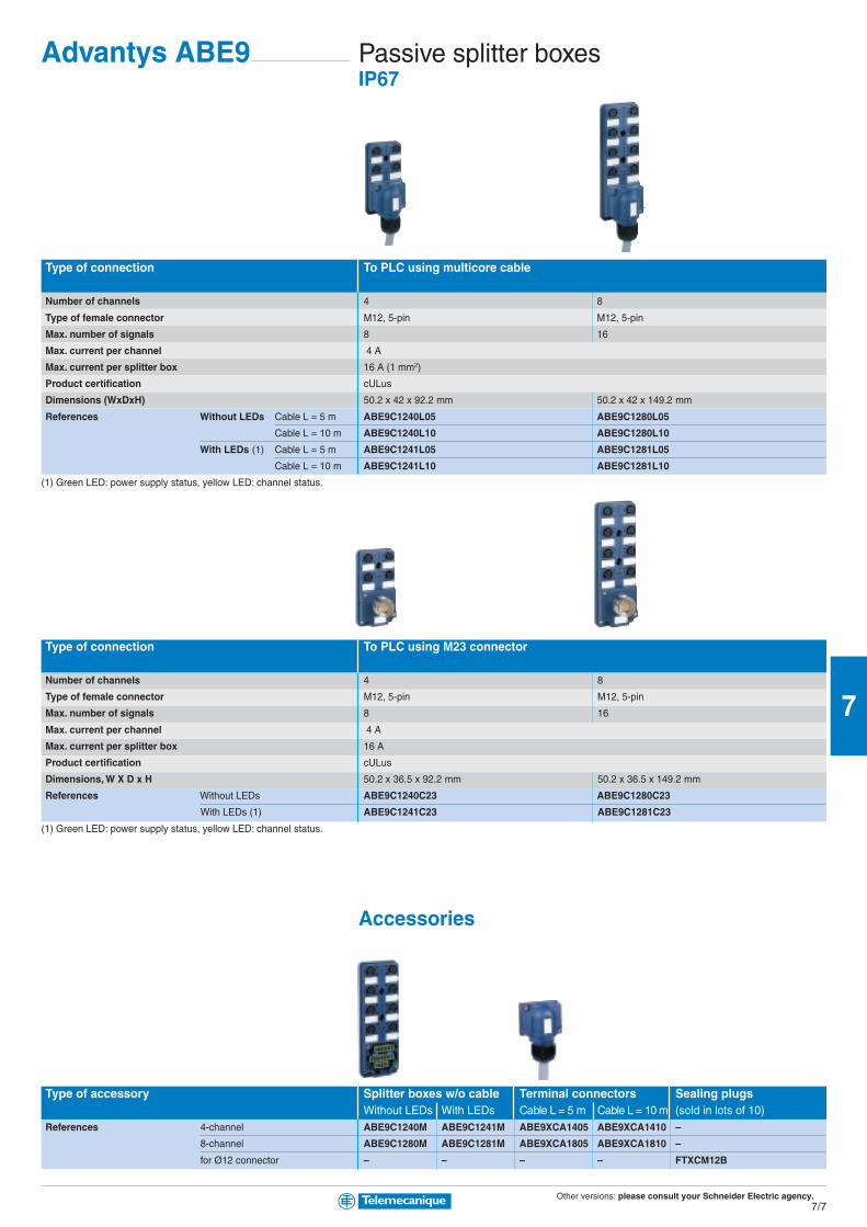
Other versions: please consult your Schneider Electric agency.7/7
7
Passive splitter boxesIP67
Type of connection To PLC using multicore cable
Number of channels 4 8
Type of female connector M12, 5-pin M12, 5-pin
Max. number of signals 8 16
Max. current per channel 4 A
Max. current per splitter box 16 A (1 mm2)
Product certification cULus
Dimensions (WxDxH) 50.2 x 42 x 92.2 mm 50.2 x 42 x 149.2 mm
References Without LEDs Cable L = 5 m ABE9C1240L05 ABE9C1280L05
Cable L = 10 m ABE9C1240L10 ABE9C1280L10
With LEDs (1) Cable L = 5 m ABE9C1241L05 ABE9C1281L05
Cable L = 10 m ABE9C1241L10 ABE9C1281L10
(1) Green LED: power supply status, yellow LED: channel status.
Type of connection To PLC using M23 connector
Number of channels 4 8
Type of female connector M12, 5-pin M12, 5-pin
Max. number of signals 8 16
Max. current per channel 4 A
Max. current per splitter box 16 A
Product certification cULus
Dimensions, W X D x H 50.2 x 36.5 x 92.2 mm 50.2 x 36.5 x 149.2 mm
References Without LEDs ABE9C1240C23 ABE9C1280C23
With LEDs (1) ABE9C1241C23 ABE9C1281C23
(1) Green LED: power supply status, yellow LED: channel status.
Accessories
Type of accessory Splitter boxes w/o cable Terminal connectors Sealing plugsWithout LEDs With LEDs Cable L = 5 m Cable L = 10 m (sold in lots of 10)
References 4-channel ABE9C1240M ABE9C1241M ABE9XCA1405 ABE9XCA1410 –
8-channel ABE9C1280M ABE9C1281M ABE9XCA1805 ABE9XCA1810 –
for Ø12 connector – – – – FTXCM12B
Advantys ABE9
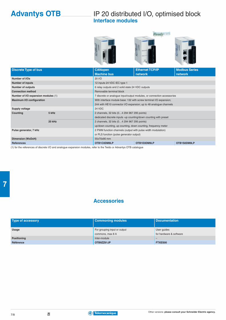
Other versions: please consult your Schneider Electric agency.7/8
7
IP 20 distributed I/O, optimised blockInterface modules
Discrete Type of bus CANopen Ethernet TCP/IP Modbus SeriesMachine bus network network
Number of I/Os 20 I/O
Number of inputs 12 inputs 24 VDC IEC type 1
Number of outputs 6 relay outputs and 2 solid state 24 VDC outputs
Connection method Removable terminal block
Number of I/O expansion modules (1) 7 discrete or analogue input/output modules, or connection accessories
Maximum I/O configuration With interface module base: 132 with screw terminal I/O expansion;
244 with HE10 connector I/O expansion; up to 48 analogue channels
Supply voltage 24 VDC
Counting 5 kHz 2 channels, 32 bits (0…4 294 967 295 points)
dedicated discrete inputs -up counting/down counting with preset
20 kHz 2 channels, 32 bits (0…4 294 967 295 points)
up/down counting, up counting, down counting, frequency meter
Pulse generator, 7 kHz 2 PWM function channels (output with pulse width modulation)
or PLS function (pulse generator output)
Dimension (WxDxH) 55x70x90 mm
References OTB1C0DM9LP OTB1E0DM9LP OTB1S0DM9LP
(1) for the references of discrete I/O and analogue expansion modules, refer to the Twido or Advantys OTB catalogue
Accessories
Type of accessory Commoning modules Documentation
Usage For grouping input or output User guides
commons, max 8 A for hardware & software
Positioning Inter-module –
Référence OTB9ZZ61JP FTXES00
Advantys OTB

Other versions: please consult your Schneider Electric agency.7/9
7
IP67 distributed I/O, optimised blockInterface modules, plastic enclosure
Type of module CANopen DeviceNet ProfiBus InterBusmachine bus Fieldbus Fieldbus Fieldbus
Number of channels 8
Type of female connector M12, 5-pin
Max. voltage / current of inputs 24 VDC type 2/200 mA
Max. voltage / current of outputs 24 VDC/1.6 A
Max. current per splitter box 8 A
Product certification cULus
Dimensions, W X D x H 63 x 50.5 x 220 mm 63 x 69 x 220 mm
Diagnostics Splitter boxes By LED for: bus and I/O undervoltage + I/O short-circuit + I/O power supply
Channels By LED for: I/O short-circuit + wire breakage fault + I/O fault
References 16 inputs FTB1CN16EP0 FTB1DN16EP0 FTB1DP16EP0 FTB1IB16EP0
8 inputs/8 outputs FTB1CN08E08SP0 FTB1DN08E08SP0 FTB1DP08E08SP0 FTB1IB08E08SP0
12 inputs/4 outputs FTB1CN12E04SP0 FTB1DN12E04SP0 FTB1DP12E04SP0 FTB1IB12E04SP0
16 configurable inputs/outputs FTB1CN16CP0 FTB1DN16CP0 FTB1DP16CP0 FTB1IB16CP0
Interface modules, metal enclosure
Type of module CANopen DeviceNet ProfiBus
Number of channels 8
Type of female connector M12, 5-pin
Max. voltage / current of inputs 24 VDC type 2/200 mA
Max. voltage / current of outputs 24 VDC/1.6 A
Max. current per splitter box 8 A
Product certification cULus
Dimensions (WxDxH) 62.7 x 38.9 x 224.7 mm
Diagnostics Splitter boxes By LED for: bus and I/O undervoltage + I/O short-circuit + I/O power supply
Channels By LED for: I/O short-circuit + wire breakage fault + I/O fault
References 16 inputs FTB1CN16EM0 FTB1DN16EM0 FTB1DP16EM0
8 inputs/8 outputs/configurable outputs FTB1CN08E08CM0 FTB1DN08E08CM0 FTB1DP08E08CM0
16 configurable inputs/outputs FTB1CN16CM0 FTB1DN16CM0 FTB1DP16CM0
Advantys FTB

Other versions: please consult your Schneider Electric agency.7/10
7
IP20 Distributed I/O, modular systemCommunication modules
Type of module NIM Ethernet TCP/IP network
Binary speed 10 Mbps
Protocol Modbus TCP/IP
Transparent Ready Class B20
Embedded Web server Standard services
Ethernet services SNMP agent, FDR client (replacement of faulty equipment), BOOTP (allocation of IP addresses by a server)
Max. number of addressable I/O modules 32 per island
Dimensions (WxDxH) 40x70x128,3 mm
Reference Standard STBNIP2212
Type of module NIM Machine bus FieldbusCANopen Fipio INTERBUS Profibus DP
Max. number of addressable I/O modules 32 per island (1) (2) 32 per island (1) 32 per island (1) (2) 32 per island (1) (2)
Binary speed 10 K…1 Mbps 1 Mbps 0.5 Mbps 9.6 K…12 Mbps
Dimensions (WxDxH) 40x70x128,3 mm
Reference Standard STBNCO2212 STBNFP2212 STBNIB2212 STBNDP2212
Basic STBNCO1010 – STBNIB1010 STBNDP1010
(1) On 7 segments max.
(2) 12 per island on 1 segment max for basic versions.
Type of module Other networksModbus Plus DeviceNet
Max. number of addressable I/O modules 32 per island 32 per island 12 per island
Speed 1 Mbps 125, 250 or 500 Kbps 125, 250 or 500 Kbps
Dimensions (WxDxH) 40x70x128,3 mm
Reference Standard STBNMP2212 STBNDN2212 –
Basic – – STBNDN1010
Connection accessoriesType of accessory Removable terminals for
24 VDC power supply DeviceNetUse All communication modules Network link DeviceNet module
Reference Screw terminals STBXTS1120 (1) STBXTS1111
Spring terminals STBXTS2120 (1) STBXTS2111
(1) To be ordered separately, sold in lots of 10.
Connection accessories: See www.telemecanique.com
Advantys STB
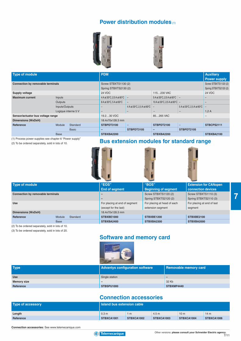
Other versions: please consult your Schneider Electric agency.7/11
7
Power distribution modules (1)
Type of module PDM AuxiliaryPower supply
Connection by removable terminals Screw STBXTS1130 (2) Screw STBXTS1120 (2)
Spring STBXTS2130 (2) Spring STBXTS2120 (2)
Supply voltage 24 VDC 115…230 VAC 24 VDC
Maximum current Inputs 4 A at 30°C, 2.5 A at 60°C – 5 A at 30°C, 2.5 A at 60°C – –
Outputs 8 A at 30°C, 5 A at 60°C – 10 A at 30°C, 2.5 A at 60°C – –
Inputs/Outputs – 4 A at 30°C, 2,5 A at 60°C – 5 A at 30°C, 2,5 A at 60°C –
Logique interne 5 V – – – – 1,2 A
Sensor/actuator bus voltage range 19.2…30 VDC 85…265 VAC –
Dimensions (WxDxH) 18.4x70x128.3 mm
Reference Module Standard STBPDT3100 – STBPDT2100 – STBCPS2111
Basic – STBPDT3105 – STBPDT2105
Base STBXBA2200 STBXBA2200 STBXBA2100
(1) Process power supplies see chapter 6 “Power supply”
(2) To be ordered separately, sold in lots of 10. Bus extension modules for standard range
Type of module “EOS” “BOS” Extension for CANopenEnd of segment Beginning of segment connection devices
Connection by removable terminals – Screw STBXTS1120 (2) Screw STBXTS1110 (3)
– Spring STBXTS2120 (2) Spring STBXTS2110 (3)
Use For placing at end of segment For placing at head of each For placing at end of last
(except for the last) extension segment segment
Dimensions (WxDxH) 18.4x70x128.3 mm
Reference Module Standard STBXBE1000 STBXBE1200 STBXBE2100
Base STBXBA2400 STBXBA2300 STBXBA2000
(2) To be ordered separately, sold in lots of 10.
(3) To be ordered separately, sold in lots of 20.
Software and memory card
Type Advantys configuration software Removable memory card
Use Single station –
Memory size – 32 Kb
Reference STBSPU1000 STBXMP4440
Connection accessoriesType of accessory Island bus extension cable
Length 0.3 m 1 m 4.5 m 10 m 14 m
Reference STBXCA1001 STBXCA1002 STBXCA1003 STBXCA1004 STBXCA1006
Connection accessories: See www.telemecanique.com

Other versions: please consult your Schneider Electric agency.7/12
7
IP20 Distributed I/O, modular systemDiscrete modules
Type of module Discrete inputs
Connection by removable terminals (1) Screw STBXTS1100 Screw STBXTS1110
Spring STBXTS2100 Spring STBXTS2110
Number of channels 2 4 6 2
Input voltage 24 VDC 115 VAC 230 VAC
Dimensions (WxDxH) 13.9x70x128.3 mm 18.4x70x128.3 mm
Reference Module Standard STBDDI3230 STBDDI3420 STBDDI3610 STBDAI5230 STBDAI7220
Basic – STBDDI3425 STBDDI3615 – –
Base STBXBA1000 STBXBA2000
(1) To be ordered separately, sold in lots of 20.
Type of module Discrete solid state outputs
Connection by removable terminals (1) Screw STBXTS1100
Spring STBXTS2100
Number of channels 2 4 6
Output voltage 24 VDC 24 VDC 24 VDC
Output current 0.5 A 2 A 0.25 A 0.5 A 0.25 A 0.5 A
Dimensions (WxDxH) 13.9x70x128.3 mm
Reference Module Standard STBDDO3200 STBDDO3230 – STBDDO3410 – STBDDO3600
Basic – – STBDDO3415 – STBDDO3605 –
Base STBXBA1000
(1) To be ordered separately, sold in lots of 20.
Type of module Discrete outputsTriac Relay
Connection by removable terminals (1) Screw STBXTS1110
Spring STBXTS2110
Number of channels 2 2 NC/NO 2 NC+NO
Output voltage 115…230 VAC 24 VDC or 115…230 VAC
Output current 2 A at 30°C, 1 A at 60°C 2 A per contact 7 A per contact
Dimensions (WxDxH) 18.4x70x128.3 mm 28.1x70x128.3 mm
Reference Module Standard STBDAO8210 STBDRC3210 STBDRA3290
Base STBXBA2000 STBXBA3000
(1) To be ordered separately, sold in lots of 20.
Connection accessories: See www.telemecanique.com
Advantys STB

Other versions: please consult your Schneider Electric agency.7/13
7
Analog modules
Type of module (3) Analog inputs
Connection by removable terminals Screw STBXTS1100 (1) / Spring STBXTS2100 (1)
Number of channels 2
Input signal - 10…+10 V 0…+10 V 0…20 mA 4…20 mA Multi-range (2)
Resolution 11 bits + sign 9 bits + sign 10 bits 12 bits 10 bits 15 bits + sign
Dimensions (WxDxH) 13.9x70x128.3 mm
Reference Module Standard STBAVI1270 – – STBACI1230 – STBART0200
Basic – STBAVI1275 STBAVI1255 – STBACI1225 –
Base STBXBA1000
(1) To be ordered separately, sold in lots of 20.
(2) Thermocouple B, E, J, K, R, S, T. Thermal probe Pt 100, Pt 1000, Ni 100, Ni 1000, cu 10, ± 80 mV.
Type of module (3) Analog outputs
Connection by removable terminals Screw STBXTS1100 (1) / Spring STBXTS2100 (1)
Number of channels 2
Output signal - 0…+10 V, - 10…+10 V 0…+10 V -10 V…+10 V 0…20 mA 4…20 mA
Resolution 11 bits + sign or 12 bits 10 bits 9 bits + signe 12 bits 10 bits
Dimensions (WxDxH) 13.9x70x128.3 mm
Reference Module Standard STBAVO1250 – – STBACO1210 –
Basic – STBAVO1255 STBAVO1265 – STBACO1225
Base STBXBA1000
(1) To be ordered separately, sold in lots of 20.Application-specific modules
Type of module (3) For motor starters CounterTego Power TeSys model U (1)
Connection by connector 1 HE10 (30 contacts) 4 RJ45 Spring STBXTS2150 (2)
Number of inputs/outputs 16 E / 8 S 12 E / 8 S 4 E / 2 S
Input voltage 24 VDC 24 VDC
Output voltage/current 24 VDC/0.1 A per channel 24 VDC/0.5 A
Number of channels 8 non reversing motor starters 4 starters-controllers 1 counter channel 40 kHz
Dimensions (WxDxH) 18.4x70x128.3 mm 28.1x70x128.3 mm
Reference Module Standard STBEPI1145 STBEPI2145 STBEHC3020
Base STBXBA2000 STBXBA3000
Connection cables STBXCA3002 (L= 1 m) 490NTW00002 (L= 2 m) –
STBXCA3003 (L= 2 m) 490NTW00005 (L= 5 m) –
(1) For 2/3-wire PNP/NPN 24 VDC sensors, 24 VDC incremental encoders, mechanical contacts
(2) To be ordered separately
(3) Requited grounding kit (conseilled for counter<40 kHz): STBXSP3000 (connecting support) + STBXSP3010 (1,5…6 mm2 terminals) + STBXSP3020 (5…11 mm2 terminals)
Connection accessories: See www.telemecanique.com
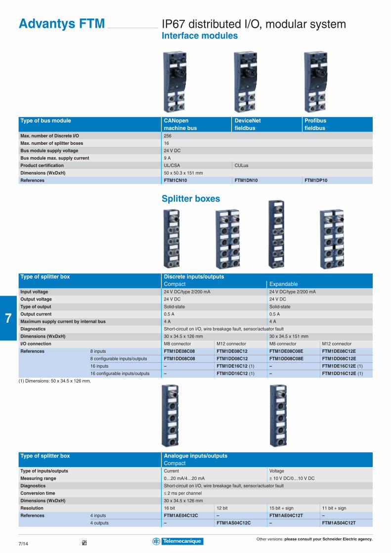
Other versions: please consult your Schneider Electric agency.7/14
7
IP67 distributed I/O, modular systemInterface modules
Advantys FTM
Type of bus module CANopen DeviceNet Profibusmachine bus fieldbus fieldbus
Max. number of Discrete I/O 256
Max. number of splitter boxes 16
Bus module supply voltage 24 V DC
Bus module max. supply current 9 A
Product certification UL/CSA CULus
Dimensions (WxDxH) 50 x 50.3 x 151 mm
References FTM1CN10 FTM1DN10 FTM1DP10
Splitter boxes
Type of splitter box Discrete inputs/outputsCompact Expandable
Input voltage 24 V DC/type 2/200 mA 24 V DC/type 2/200 mA
Output voltage 24 V DC 24 V DC
Type of output Solid-state Solid-state
Output current 0.5 A 0.5 A
Maximum supply current by internal bus 4 A 4 A
Diagnostics Short-circuit on I/O, wire breakage fault, sensor/actuator fault
Dimensions (WxDxH) 30 x 34.5 x 126 mm 30 x 34.5 x 151 mm
I/O connection M8 connector M12 connector M8 connector M12 connector
References 8 inputs FTM1DE08C08 FTM1DE08C12 FTM1DE08C08E FTM1DE08C12E
8 configurable inputs/outputs FTM1DD08C08 FTM1DD08C12 FTM1DD08C08E FTM1DD08C12E
16 inputs – FTM1DE16C12 (1) – FTM1DE16C12E (1)
16 configurable inputs/outputs – FTM1DD16C12 (1) – FTM1DD16C12E (1)
(1) Dimensions: 50 x 34.5 x 126 mm.
Type of splitter box Analogue inputs/outputsCompact
Type of inputs/outputs Current Voltage
Measuring range 0…20 mA/4…20 mA ± 10 V DC/0…10 V DC
Diagnostics Short-circuit on I/O, wire breakage fault, sensor/actuator fault
Conversion time ≤ 2 ms per channel
Dimensions (WxDxH) 30 x 34.5 x 126 mm
Resolution 16 bit 12 bit 15 bit + sign 11 bit + sign
References 4 inputs FTM1AE04C12C – FTM1AE04C12T –
4 outputs – FTM1AS04C12C – FTM1AS04C12T
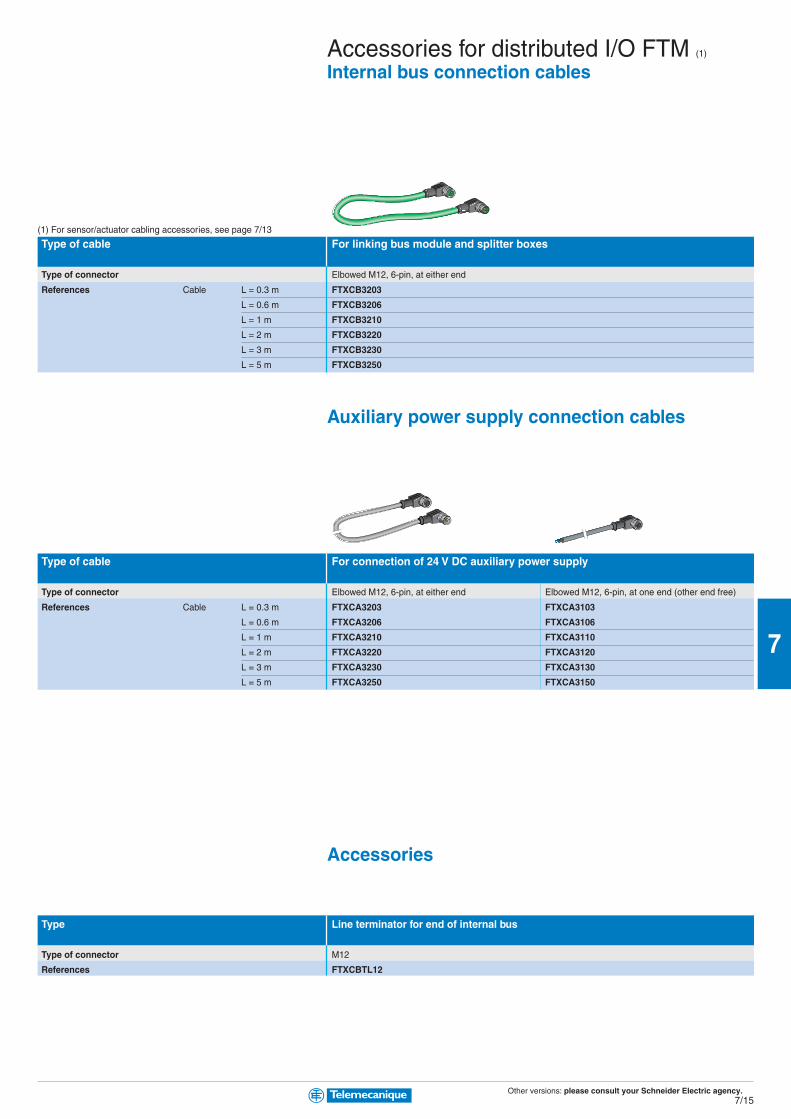
Other versions: please consult your Schneider Electric agency.7/15
7
Accessories for distributed I/O FTM (1)
Internal bus connection cables
(1) For sensor/actuator cabling accessories, see page 7/13
Type of cable For linking bus module and splitter boxes
Type of connector Elbowed M12, 6-pin, at either end
References Cable L = 0.3 m FTXCB3203
L = 0.6 m FTXCB3206
L = 1 m FTXCB3210
L = 2 m FTXCB3220
L = 3 m FTXCB3230
L = 5 m FTXCB3250
Auxiliary power supply connection cables
Type of cable For connection of 24 V DC auxiliary power supply
Type of connector Elbowed M12, 6-pin, at either end Elbowed M12, 6-pin, at one end (other end free)
References Cable L = 0.3 m FTXCA3203 FTXCA3103
L = 0.6 m FTXCA3206 FTXCA3106
L = 1 m FTXCA3210 FTXCA3110
L = 2 m FTXCA3220 FTXCA3120
L = 3 m FTXCA3230 FTXCA3130
L = 5 m FTXCA3250 FTXCA3150
Accessories
Type Line terminator for end of internal bus
Type of connector M12
References FTXCBTL12
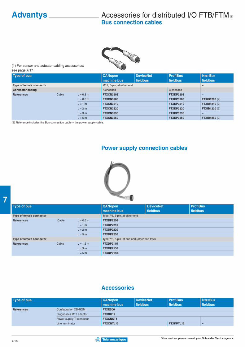
Other versions: please consult your Schneider Electric agency.7/16
7
Accessories for distributed I/O FTB/FTM (1)
Bus connection cables
Type of bus CANopen DeviceNet ProfiBus INTERBUS
machine bus fieldbus fieldbus fieldbusType of female connector M12, 5-pin, at either end –
Connector coding A encoded B encoded –
References Cable L = 0.3 m FTXCN3203 FTXDP3203 –
L = 0.6 m FTXCN3206 FTXDP3206 FTXIB1206 (2)
L = 1 m FTXCN3210 FTXDP3210 FTXIB1210 (2)
L = 2 m FTXCN3220 FTXDP3220 FTXIB1220 (2)
L = 3 m FTXCN3230 FTXDP3230 –
L = 5 m FTXCN3250 FTXDP3250 FTXIB1250 (2)
(2) Reference includes the Bus connection cable + the power supply cable.
Power supply connection cables
Type of bus CANopen DeviceNet ProfiBusmachine bus fieldbus fieldbus
Type of female connector Type 7/8, 5-pin, at either end
References Cable L = 0.6 m FTXDP2206
L = 1 m FTXDP2210
L = 2 m FTXDP2220
L = 5 m FTXDP2250
Type of female connector Type 7/8, 5-pin, at one end (other end free)
References Cable L = 1.5 m FTXDP2115
L = 3 m FTXDP2130
L = 5 m FTXDP2150
Accessories
Type of bus CANopen DeviceNet ProfiBus INTERBUS
machine bus fieldbus fieldbus fieldbusReferences Configuration CD-ROM FTXES00
Diagnostics M12 adaptor FTXDG12
Power supply T-connector FTXCNCT1 –
Line terminator FTXCNTL12 FTXDPTL12 –
(1) For sensor and actuator cabling accessories:see page 7/17
Advantys

Other versions: please consult your Schneider Electric agency.7/17
7
Accessories for sensors/actuatorsM12 / M12 jumper cables
Type Male / Female jumper cables
Type of male connector, interface side M12, 3-pin, straight, screw thread M12, 4-pin, straight, screw thread M12, 5-pin, straight, screw thread
Type of female connector, sensor side M12, 3-pin, straight, screw thread M12, 4-pin, straight, screw thread M12, 5-pin, straight, screw thread
Cable PUR, black PUR, black PUR, black
References Cable L = 1 m XZCR1511040A1 XZCR1511041C1 XZCR1511064D1
L = 2 m XZCR1511040A2 XZCR1511041C2 XZCR1511064D2
M8/M8, M8/M12 and M12/DIN jumper cables
Type Male / Female jumper cables
Type of male connector, interface side M8, 3-pin M12, 3-pin M12, 3-pin M12, 3-pin
straight, screw thread straight, screw thread straight, screw thread straight, screw thread
Type of female connector, sensor side M8, 3-pin M8, 3-pin M8, 3-pin DIN 43650A
straight, screw thread straight, clip together straight, screw thread elbowed, screw thread
Cable PUR, black PUR, black PUR, black PUR, black
References Cable L = 1 m XZCR2705037R1 XZCR1501040G1 XZCR1509040H1 XZCR1523062K1
L = 2 m XZCR2705037R2 XZCR1501040G2 XZCR1509040H2 XZCR1523062K2
Pre-wired connectors and splitter box
Type Connectors Pre-wired connectors Splitter box “Y”
Type of male connector, interface side M12, 4-pin M8, 3-pin M12, 5-pin, straight, screw thread 1 x M12 1 x M12
Type of female connector, sensor side – – – 2 x M12 2 x M8
Cable – – PUR, black –
References Straight connector, screw thread XZCC12MDM40B XZCC8MDM30V – FTXCY1212 FTXCY1208
Elbowed connector, screw thread XZCC12MCM40B – – – –
Cable L = 0.5 m – – XZCP1564L05 – –
L = 2 m – – XZCP1564L2 – –

1
2
2 2
2
1
1
2 2
2
1
2
1
3
3
3
2
1
1
2
1
2
1
2
3
AS
-Int
erfa
ce c
ablin
g sy
stem
The essentialguideA simplifiedselection guideenabling you toquickly select allthe necessaryproducts andaccessories tobuild yourinstallation.
The cabling system thatmeets your needs forindustrial automation systems
AS-Interface With the «Smart Cable» opt for:
b SimplicityA quick and expandable cabling system:> Only 1 cable for connecting all the components of an automationsystem> Management of communications integrated in the products
b Maximum securityAS-Interface significantly improves the reliability, availability andsafety of your machine:> Cabling errors are eliminated> Risk of electrical connection failure greatly reduced> High immunity to electromagnetic interference (EMC)> The machine’s safety function is fully integrated with AS-InterfaceSafety at Work.
b Up to 40% savings in costs> Savings in time for design, installation, setting-up andcommissioning> Savings in space required in enclosures due to smaller productsand elimination of intermediate boxes> Control cabling eliminated and reduction in cable ducting
IP20 interfaceIP67 interface
Dedicated controlcomponentsDedicated dialoguecomponents
Safety monitorSafety interface
Power supply units andearth fault detectionAS-Interface master
The “Smart Cable”
(Actuator Sensor Interface)
8/0

These IP20 or IP67 interfaces allow anystandard automation component to beconnected to the AS-Interface cable.
These handle automation functions and canbe connected directly to the AS-Interfacecable. An integrated circuit (ASIC) built intothe products manages all interfacingfunctions and communication.
The incorporation of safety functions in theAS-Interface system is achieved by addinga safety monitor and safety interfaces,connected together with other standardAS-Interface components on the sameyellow cable.
Sensors and actuators are connected tothe processing unit by the AS-Interfacesystem. This system comprises a cable,accessories, a master module and a powersupply unit.
The terminals enable the assigning of anaddress to each interface and componentin the system and diagnostics of theinstallation.
8/1
8
Contents
Advantys interfaces forgeneric products ........................................................ 8/2
b IP20 interfaces
b IP67 interfaces
Dedicated components ........................................ 8/4
b For control
b For dialogue
Safety solutions(see Chapter 9 “Machine safety”)
b Safety monitors
b Safety interfaces
Installation system ......................................... 8/6 to 8/8
b Master modules,power supply units
b Cables, repeaters
b Accessories
Tools ........................................................................................ 8/9
b Adjustment andaddressing terminals

Other versions: please consult your Schneider Electric agency.8/2
8
AS-Interface Advantys interfaces for generic productsIP20 for mounting in enclosure
Modular interface, width 25 mm Analogue DigitalV2.1 with standard addressingNumber of inputs 2 (0…10V) 2 (0/4…20mA) 4 4 4 isolated
Number of outputs – – 4 relay, 2A 4 solid state, 0.5A 4 solid state, 0.5A
Type of addressing Standard
Supply by AS-Interface Inputs and sensor supply (200 mA max.) –
Supply by 24 VDC external source (black AUX cable) – – – Outputs (2)
AS-Interface profile S.7.3.F.D S.7.3.F.D S.7.0.F.E S.7.0.F.E S.7.0.F.E
Maximum consumption from AS-Interface (excluding sensor supply) 60 mA 60 mA 110 mA 50 mA 20 mA
Dimensions (WxDxH) 25x77x87 mm 25x77x87 mm 25x77x87 mm 25x77x87 mm 25x77x87 mm
References ASI20MA2VU ASI20MA2VI ASI20MT4I4OR ASI20MT4I4OS ASI20MT4I4OSA
Accessory (1) for connection to flat cables XZCG0122 XZCG0122 XZCG0122 ASIDCPFIL20 ASIDCPFIL20
(1) Or direct screw terminal connection (without accessory), (other accessories, see page 8/9).
(2) Inputs, outputs and sensor supply (200 mA max.).
Modular interface, width 25 mm DigitalV2.1 with extended (A/B) addressingNumber of inputs 4 2 4 4 4 isolated
Number of outputs – 1 triac, 2A 3 relay, 2A 3 solid state, 0.5A 3 solid state, 0.5A
Type of addressing Extended (A/B)
Supply by AS-Interface Inputs and sensor supply (200 mA max.) (3) –
Supply by 24 VDC external source (black AUX cable) – – – Outputs (2)
AS-Interface profile S.0.A.7.0 S.3.A.7.0 S.7.A.7.0 S.7.A.7.0 S.7.A.7.0
Maximum consumption from AS-Interface (excluding sensor supply) 50 mA 40 mA 90 mA 50 mA 20 mA
Dimensions (WxDxH) 25x77x87 mm 25x77x87 mm 25x77x87 mm 25x77x87 mm 25x77x87 mm
References ASI20MT4IE ASI20MT2I1OTE ASI20MT4I3ORE ASI20MT4I3OSE ASI20MT4I3OSAE
Accessory (1) for connection to flat cables XZCG0122 XZCG0122 XZCG0122 ASIDCPFIL20 ASIDCPFIL20
(1) Or direct screw terminal connection (without accessory), (other accessories, see page 8/9).
(2) Inputs, outputs and sensor supply (200 mA max.).
(3) Except ASI20MT4I3ORE (170 mA max.).
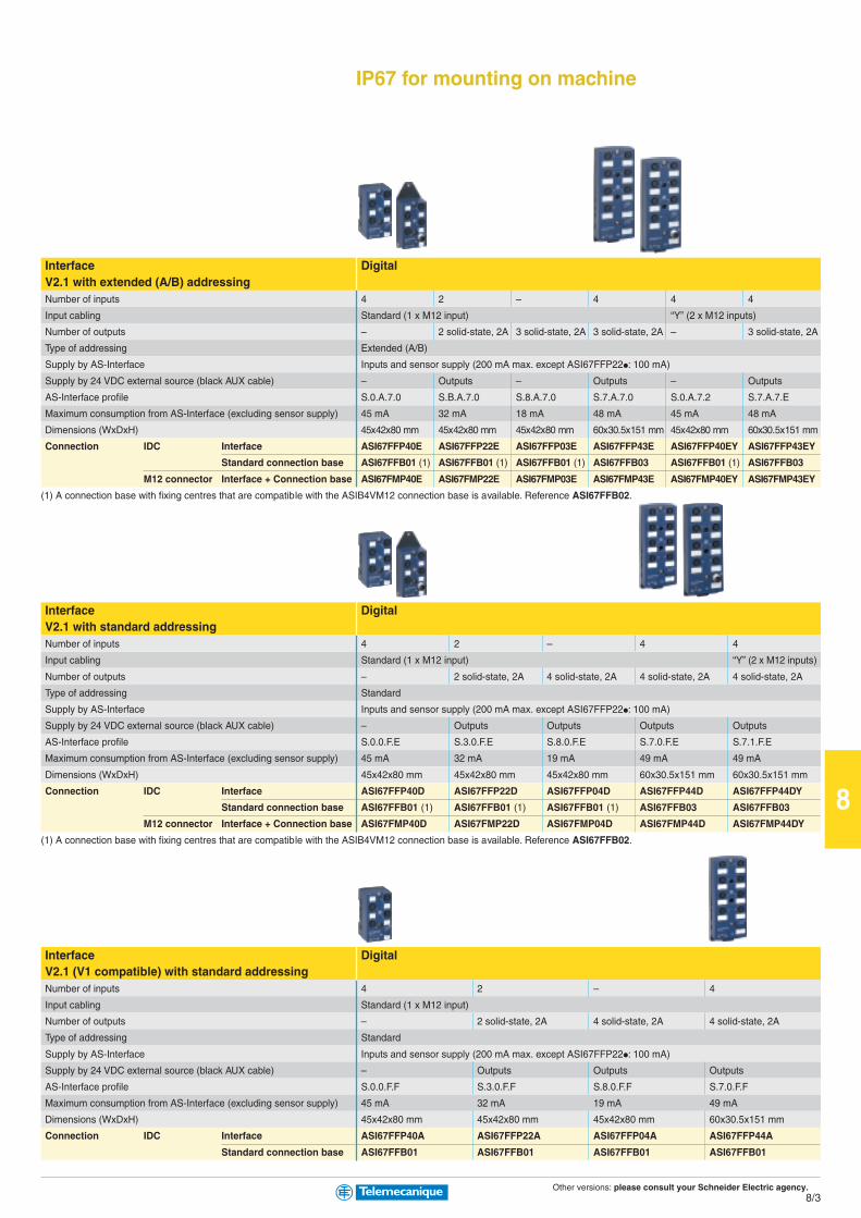
Other versions: please consult your Schneider Electric agency.8/3
8
IP67 for mounting on machine
Interface DigitalV2.1 with extended (A/B) addressingNumber of inputs 4 2 – 4 4 4
Input cabling Standard (1 x M12 input) “Y” (2 x M12 inputs)
Number of outputs – 2 solid-state, 2A 3 solid-state, 2A 3 solid-state, 2A – 3 solid-state, 2A
Type of addressing Extended (A/B)
Supply by AS-Interface Inputs and sensor supply (200 mA max. except ASI67FFP22•: 100 mA)
Supply by 24 VDC external source (black AUX cable) – Outputs – Outputs – Outputs
AS-Interface profile S.0.A.7.0 S.B.A.7.0 S.8.A.7.0 S.7.A.7.0 S.0.A.7.2 S.7.A.7.E
Maximum consumption from AS-Interface (excluding sensor supply) 45 mA 32 mA 18 mA 48 mA 45 mA 48 mA
Dimensions (WxDxH) 45x42x80 mm 45x42x80 mm 45x42x80 mm 60x30.5x151 mm 45x42x80 mm 60x30.5x151 mm
Connection IDC Interface ASI67FFP40E ASI67FFP22E ASI67FFP03E ASI67FFP43E ASI67FFP40EY ASI67FFP43EY
Standard connection base ASI67FFB01 (1) ASI67FFB01 (1) ASI67FFB01 (1) ASI67FFB03 ASI67FFB01 (1) ASI67FFB03
M12 connector Interface + Connection base ASI67FMP40E ASI67FMP22E ASI67FMP03E ASI67FMP43E ASI67FMP40EY ASI67FMP43EY
(1) A connection base with fixing centres that are compatible with the ASIB4VM12 connection base is available. Reference ASI67FFB02.
Interface DigitalV2.1 with standard addressingNumber of inputs 4 2 – 4 4
Input cabling Standard (1 x M12 input) “Y” (2 x M12 inputs)
Number of outputs – 2 solid-state, 2A 4 solid-state, 2A 4 solid-state, 2A 4 solid-state, 2A
Type of addressing Standard
Supply by AS-Interface Inputs and sensor supply (200 mA max. except ASI67FFP22•: 100 mA)
Supply by 24 VDC external source (black AUX cable) – Outputs Outputs Outputs Outputs
AS-Interface profile S.0.0.F.E S.3.0.F.E S.8.0.F.E S.7.0.F.E S.7.1.F.E
Maximum consumption from AS-Interface (excluding sensor supply) 45 mA 32 mA 19 mA 49 mA 49 mA
Dimensions (WxDxH) 45x42x80 mm 45x42x80 mm 45x42x80 mm 60x30.5x151 mm 60x30.5x151 mm
Connection IDC Interface ASI67FFP40D ASI67FFP22D ASI67FFP04D ASI67FFP44D ASI67FFP44DY
Standard connection base ASI67FFB01 (1) ASI67FFB01 (1) ASI67FFB01 (1) ASI67FFB03 ASI67FFB03
M12 connector Interface + Connection base ASI67FMP40D ASI67FMP22D ASI67FMP04D ASI67FMP44D ASI67FMP44DY
(1) A connection base with fixing centres that are compatible with the ASIB4VM12 connection base is available. Reference ASI67FFB02.
Interface DigitalV2.1 (V1 compatible) with standard addressingNumber of inputs 4 2 – 4
Input cabling Standard (1 x M12 input)
Number of outputs – 2 solid-state, 2A 4 solid-state, 2A 4 solid-state, 2A
Type of addressing Standard
Supply by AS-Interface Inputs and sensor supply (200 mA max. except ASI67FFP22•: 100 mA)
Supply by 24 VDC external source (black AUX cable) – Outputs Outputs Outputs
AS-Interface profile S.0.0.F.F S.3.0.F.F S.8.0.F.F S.7.0.F.F
Maximum consumption from AS-Interface (excluding sensor supply) 45 mA 32 mA 19 mA 49 mA
Dimensions (WxDxH) 45x42x80 mm 45x42x80 mm 45x42x80 mm 60x30.5x151 mm
Connection IDC Interface ASI67FFP40A ASI67FFP22A ASI67FFP04A ASI67FFP44A
Standard connection base ASI67FFB01 ASI67FFB01 ASI67FFB01 ASI67FFB01

Other versions: please consult your Schneider Electric agency.8/4
8
AS-Interface Dedicated componentsFor control
Starter in insulated enclosure (1) Control byV1 Black rotary knob (blue bkgrnd.) Pushbuttons Red rotary knob (yellow bkgrnd.)
Type of addressing Standard Standard Standard
Supply by AS-Interface Inputs, sensor supply (2) Inputs, sensor supply
Supply by 24 VDC external source (black AUX cable) (2) (2) Contactors
AS-Interface profile S.7.D S.7.D S.7.F
Maximum consumption from AS-Interface 120 mA 120 mA 12 mA
Dimensions (WxDxH) 175x175x195 mm 175x175x195 mm 175x175x195 mm
References (3) Non reversing LF1PppppppppppD LF1MppppppppppD LF7PppppppppppD
(see table below) Reversing LF2PppppppppppD LF2MppppppppppD LF8PppppppppppD
Connection to AS-Interface and external supply (AUX) by accessory for flat cable: ASIDCPM12D03 (AS-Interface and AUX cables) or XZCG01205D (AS-Interface cable).
(1) For an LF1 or LF2 starter in a metal enclosure, add the letter M after the 3rd digit in the references listed above (example: LF1P02D becomes LF1MP02D).
(2) Contactors supplied by AS-Interface or external source, configurable directly on terminal block.
(3) To complete the reference, replace pppppppppp by the numbers indicated in the table below. (Example: LF1PppppppppppD becomes LF1P00D).
kW A pppppppppp kW A pppppppppp
– without MCB 00 0.75 1.6…2.5 07
0.06 0.16…0.25 02 1.1 / 1.5 2.5…4 08
0.09 0.25…0.40 03 2.2 4…6.3 10
0.12 / 0.18 0.40…0.63 04 3 / 4 6…10 14
0.25 0.63…1 05 5.5 9…14 16
0.37/ 0.55 1…1.6 06
kW= Motor power ratings in category AC-3, 400/415V, in kilowatts.
A= Adjustable range of circuit-breaker thermal trips, in amperes.
Communication interface for TeSys Model U Tego PowerV2.1 V1
Type of addressing Standard Standard 2 addresses
Supply by AS-Interface – –
Supply by external source (AUX) Coil Contactors
AS-Interface profile S.7.D.F.0 S.7.0
Maximum consumption from AS-Interface 30 mA280 mA
Dimensions (WxDxH) depending on LU model 35x129x254 mm
References ASILUFC5 APP1CAS2
Recommended accessory for connection to AS-Interface cable (4) ASIDCPFIL20 ASIDCPFIL20
(4) Or direct screw terminal connection to AS-Interface and external supply (AUX), (other accessories, see page 8/9).

Other versions: please consult your Schneider Electric agency.8/5
8
For dialogue
Keypads and Control stations Control stations with 2 pushbuttonsV1 Black and white Illuminated
Type of addressing Standard Standard
Supply by AS-Interface Buttons Buttons and pilot lights
Supply by external source (AUX) – –
AS-Interface profile S.3.F S.3.F
Consumption from AS-Interface < 40 mA < 80 mA
Dimensions (WxDxH) 68x62x128 mm 68x68x128 mm
References XALS2001 XALS2003
Recommended accessory for connection to AS-Interface cable (4) ASIDCPM12D03 ASIDCPM12D03
(4) Or direct screw terminal connection to AS-Interface and external supply (AUX), (other accessories, see page 8/9).
Interface For 2 control units and 2 pilot lightsV1Number of pages available –
Number of inputs 2
Number of outputs 2 solid state, 0.5A
Type of addressing Standard
Supply by AS-Interface Inputs and pilot lights
AS-Interface profile S.3.F
Maximum consumption from AS-Interface 80 mA
Dimensions (WxDxH) 52x15x38 mm
References XALSZ1
Direct screw terminal connection to AS-Interface or by accessory for flat cable: XZCG0122, (other accessories, see page 8/9).
Indicator banks, Ø 70 mm (7) Base units and cover Illuminated units AudibleV1 “Flash” discharge tube Steady light unitType of addressing Standard Standard – – –
Connection to AS-Interface cable and AUX (male M12 connector) yes yes, remote L=1m – – –
Supply by AS-Interface (5) (5) – – –
Supply by external source (AUX) (5) (5) – – –
AS-Interface profile S.8.F S.8.F – – –
Consumption from AS-Interface, supply by AS-Interface / external 250 / 30 mA 250 / 30 mA – – –
Light source – – 5 Joule LED –
Buzzer – – – – 70…80 db at 1m
References XVBC21A XVBC21B XVBC6Bppppp (6) XVBC2Bppppp (6) XVBC9B
Recommended accessory for connection to AS-Interface cable & AUX ASIDCPM12D03 XZCG0120 – – –
(5) Illuminated units supplied by AS-Interface or externally, configurable by shunt.
(6) To complete the reference, replace the ppppp by the following number designating the colour: green: 3, red: 4, orange: 5, blue: 6, clear: 7, yellow: 8.
(7) To obtain a complete indicator bank, order a base unit + the illuminated or audible units (5 units maximum).

Other versions: please consult your Schneider Electric agency.8/6
8
1Current in A at 30 V AS-Interface
Cur
rent
in A
at 2
4 V
0
123456 5,8
4,5
3
7
2 3 4 5
AS-Interface Installation systemMaster modules
Platform Twido Premium Micro Quantum
Maximum number of master modules per PLC 2 2, 4 or 8 depending on processor 1 8 (1)
Compatibility with AS-Interface interfaces and components V1 / V2.1 V1 / V2.1 V1 V1
Direct connection to AS-Interface cable by terminal block by terminal block by terminal block by terminal block
Maximum number of addresses 62 62 31 31
Type of addressing Standard/Extended (A/B) Standard/Extended (A/B) Standard Standard
Compatibility with analogue interfaces Yes Yes – –
Compatibility with safety interfaces Yes Yes Yes Yes
AS-Interface profile M.3 M.2.E M.2 M.2
References TWDNOI10M3 TSXSAY1000 TSXSAZ10 140EIA92100
(1) 4 per local rack, 4 per remote I/O, 2 per distributed I/O.
Power supply units
Type of supply AS-Interface AS-Interface + Auxiliary
Input voltage 100…240 VAC 100…240 VAC 100…240 VAC 100…120 & 200…240 VAC
AS-Interface output voltage 30 VDC 30 VDC 30 VDC 30 VDC
Auxiliary output voltage – – 24 VDC 24 VDC
AS-Interface nominal power 73 W 146 W 73 W 61-153 W
Auxiliary nominal power – – 72 W 72-168 W
AS-Interface nominal current 2.4 A 4.8 A 2.4 A 5 A (2)
AUX nominal current – – 3 A 7 A (2)
Direct connection to AS-Interface cable by terminal block by terminal block by terminal block by terminal block
Dimensions (WxDxH) 54x120x120 mm 81x120x120 mm 81x120x120 mm 225x135x151.5 mm
References without earth fault detection ASIABLB3002 ASIABLB3004 ASIABLM3024 TSXSUPA05
with earth fault detection ASIABLD3002 ASIABLD3004 – –
(2) Power supply unit with constant maximum output, see curve above.
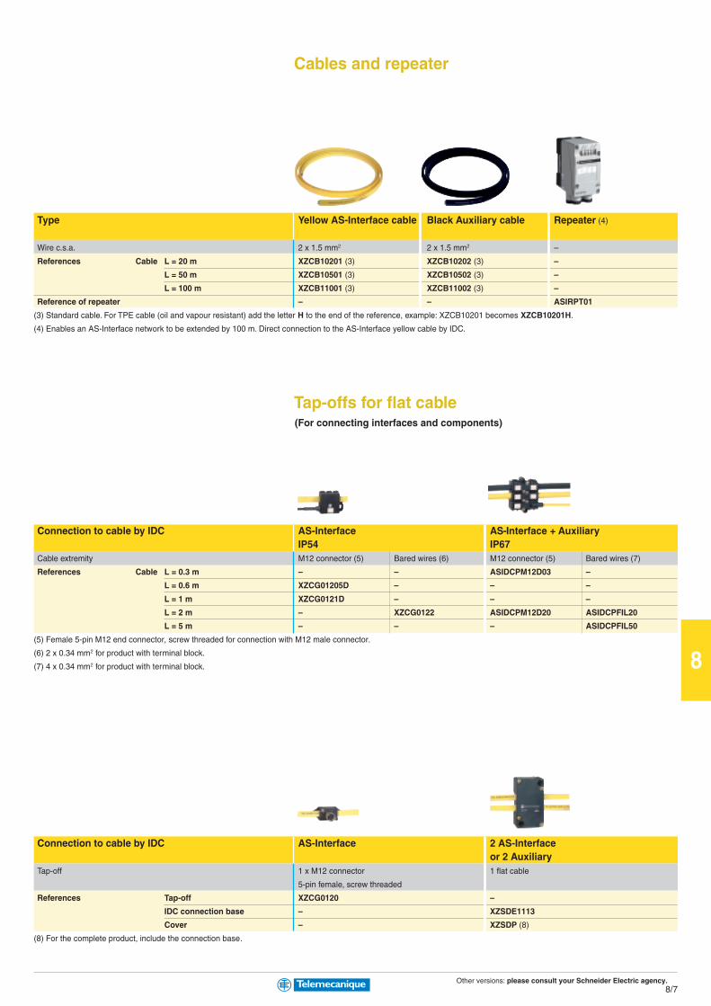
Other versions: please consult your Schneider Electric agency.8/7
8
Cables and repeater
Type Yellow AS-Interface cable Black Auxiliary cable Repeater (4)
Wire c.s.a. 2 x 1.5 mm2 2 x 1.5 mm2 –
References Cable L = 20 m XZCB10201 (3) XZCB10202 (3) –
L = 50 m XZCB10501 (3) XZCB10502 (3) –
L = 100 m XZCB11001 (3) XZCB11002 (3) –
Reference of repeater – – ASIRPT01
(3) Standard cable. For TPE cable (oil and vapour resistant) add the letter H to the end of the reference, example: XZCB10201 becomes XZCB10201H.
(4) Enables an AS-Interface network to be extended by 100 m. Direct connection to the AS-Interface yellow cable by IDC.
Tap-offs for flat cable(For connecting interfaces and components)
Connection to cable by IDC AS-Interface AS-Interface + AuxiliaryIP54 IP67
Cable extremity M12 connector (5) Bared wires (6) M12 connector (5) Bared wires (7)
References Cable L = 0.3 m – – ASIDCPM12D03 –
L = 0.6 m XZCG01205D – – –
L = 1 m XZCG0121D – – –
L = 2 m – XZCG0122 ASIDCPM12D20 ASIDCPFIL20
L = 5 m – – – ASIDCPFIL50
(5) Female 5-pin M12 end connector, screw threaded for connection with M12 male connector.
(6) 2 x 0.34 mm2 for product with terminal block.
(7) 4 x 0.34 mm2 for product with terminal block.
Connection to cable by IDC AS-Interface 2 AS-Interfaceor 2 Auxiliary
Tap-off 1 x M12 connector 1 flat cable
5-pin female, screw threaded
References Tap-off XZCG0120 –
IDC connection base – XZSDE1113
Cover – XZSDP (8)
(8) For the complete product, include the connection base.
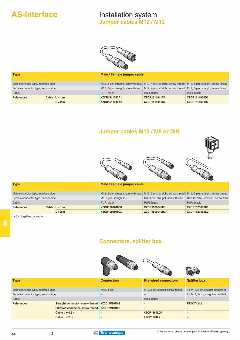
Other versions: please consult your Schneider Electric agency.8/8
8
AS-Interface Installation systemJumper cables M12 / M12
Type Male / Female jumper cable
Male connector type, interface side M12, 3-pin, straight, screw thread. M12, 4-pin, straight, screw thread. M12, 5-pin, straight, screw thread.
Female connector type, sensor side M12, 3-pin, straight, screw thread. M12, 4-pin, straight, screw thread. M12, 5-pin, straight, screw thread.
Cable PUR, black PUR, black PUR, black
References Cable L = 1 m XZCR1511040A1 XZCR1511041C1 XZCR1511064D1
L = 2 m XZCR1511040A2 XZCR1511041C2 XZCR1511064D2
Jumper cables M12 / M8 or DIN
Type Male / Female jumper cable
Male connector type, interface side M12, 3-pin, straight, screw thread. M12, 3-pin, straight, screw thread. M12, 3-pin, straight, screw thread.
Female connector type, sensor side M8, 3-pin, straight (1) M8, 3-pin, straight, screw thread. DIN 43650A, elbowed, screw thrd.
Cable PUR, black PUR, black PUR, black
References Cable L = 1 m XZCR1501040G1 XZCR1509040H1 XZCR1523062K1
L = 2 m XZCR1501040G2 XZCR1509040H2 XZCR1523062K2
(1) Clip together connector.
Connectors, splitter box
Type Connectors Pre-wired connectors Splitter box
Male connector type, interface side M12, 4-pin M12, 5-pin, straight, screw thread. 1 x M12, 5-pin, straight, screw thrd.
Female connector type, sensor side – – 2 x M12, 5-pin, straight, screw thrd.
Cable – PUR, black –
References Straight connector, screw thread. XZCC12MDM40B – FTXCY1212
Elbowed connector, screw thread. XZCC12MCM40B – –
Cable L = 0.5 m – XZCP1564L05 –
Cable L = 2 m – XZCP1564L2 –
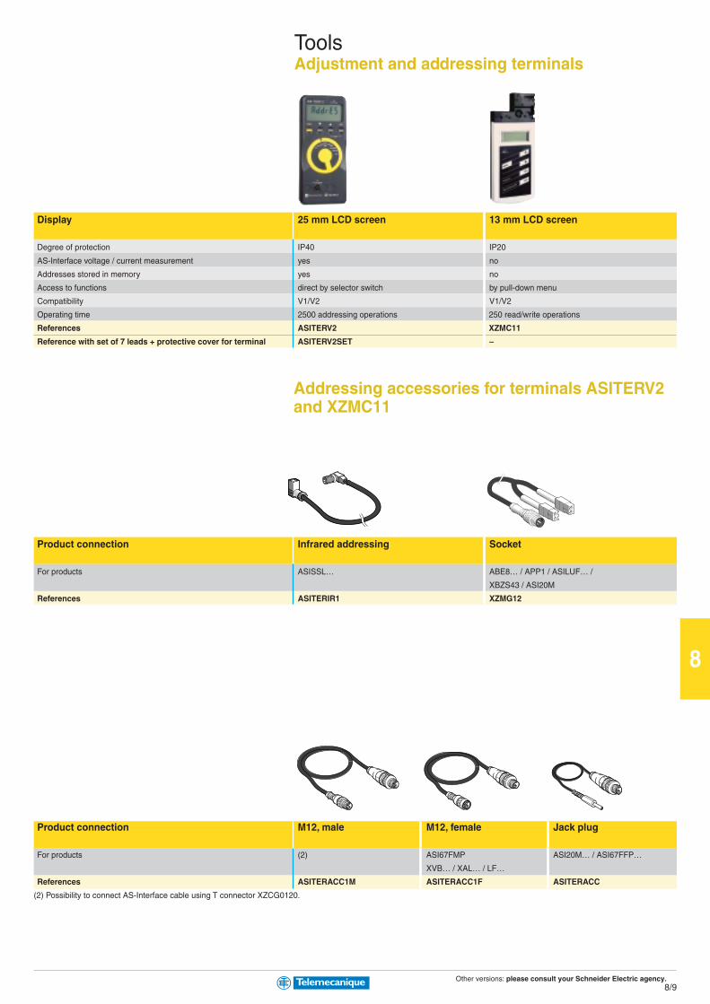
Other versions: please consult your Schneider Electric agency.8/9
8
ToolsAdjustment and addressing terminals
Display 25 mm LCD screen 13 mm LCD screen
Degree of protection IP40 IP20
AS-Interface voltage / current measurement yes no
Addresses stored in memory yes no
Access to functions direct by selector switch by pull-down menu
Compatibility V1/V2 V1/V2
Operating time 2500 addressing operations 250 read/write operations
References ASITERV2 XZMC11
Reference with set of 7 leads + protective cover for terminal ASITERV2SET –
Addressing accessories for terminals ASITERV2and XZMC11
Product connection Infrared addressing Socket
For products ASISSL… ABE8… / APP1 / ASILUF… /
XBZS43 / ASI20M
References ASITERIR1 XZMG12
Product connection M12, male M12, female Jack plug
For products (2) ASI67FMP ASI20M… / ASI67FFP…
XVB… / XAL… / LF…
References ASITERACC1M ASITERACC1F ASITERACC
(2) Possibility to connect AS-Interface cable using T connector XZCG0120.
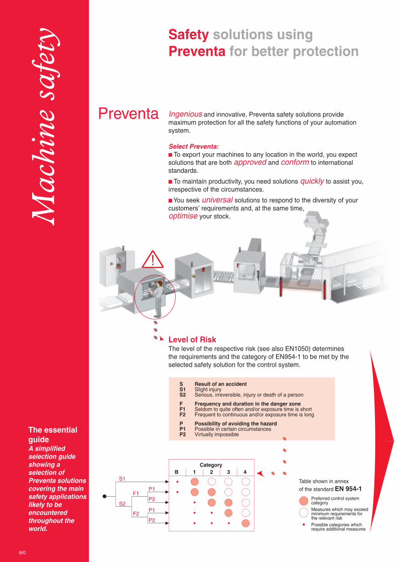
B 1 2 3 4S1
S2
F1
F2
P1
P2
P1
P2
!
Mac
hine
saf
ety
The essentialguideA simplifiedselection guideshowing aselection ofPreventa solutionscovering the mainsafety applicationslikely to beencounteredthroughout theworld.
Safety solutions usingPreventa for better protection
Preventa Ingenious and innovative, Preventa safety solutions providemaximum protection for all the safety functions of your automationsystem.
Select Preventa:b To export your machines to any location in the world, you expectsolutions that are both approved and conform to internationalstandards.
b To maintain productivity, you need solutions quickly to assist you,irrespective of the circumstances.
b You seek universal solutions to respond to the diversity of yourcustomers’ requirements and, at the same time,optimise your stock.
Level of RiskThe level of the respective risk (see also EN1050) determinesthe requirements and the category of EN954-1 to be met by theselected safety solution for the control system.
S Result of an accidentS1 Slight injuryS2 Serious, irreversible, injury or death of a person
F Frequency and duration in the danger zoneF1 Seldom to quite often and/or exposure time is shortF2 Frequent to continuous and/or exposure time is long
P Possibility of avoiding the hazardP1 Possible in certain circumstancesP2 Virtually impossible
Category
Table shown in annex
of the standard EN 954-1Preferred control systemcategoryMeasures which may exceedminimum requirements forthe relevant riskPossible categories whichrequire additional measures
9/0

You have defined your controlsystem category
The schematic library designed by SchneiderElectric assists you in selecting your optimalsolution, by:
providing typical schematics for thevarious safety functions,
enabling selection and integration of theschematic in Autocad format.
Establishment of the ordering referencesby direct access to the electronic catalogue.
Symbol Reference
S1 ZB4 BS844AND ZB4 BZ104
S2 ZB4 BA4AND ZB4 BZ104
S3 ZB4 BA1AND ZB4 BZ101
S4 XCS-M3910L•S5 XCS-M3910L•Module XPS-MP11123KM1 LC1KM2 LC1
9/1
9
C o n t e n t s
Automation ............................................................. 9/2 to 9/7b Safety PLCsb Safety controllers and modules
AS-Interface Safety at work ............... 9/8 and 9/9b Safety monitors and interfaces
Detection ............................................................... 9/10 to 9/13b Safety switchesb Safety limit switches and matsb Safety light curtains
Operator dialogue ....................................... 9/14 to 9/18b Emergency stopsb Foot switchesb Two-hand control and enabling switchesb Products for explosive atmospheres(see chapter 10 “Explosive Atmospheres”)
Motor control .................................................... 9/19 to 9/21b Switch disconnectorsb TeSys motor starters

Other versions: please consult your Schneider Electric agency.
9
9 / 2
Safety PLC type Compact
Number of inputs Digital 20 20 24 24 24
Analogue – – 8 8 8
Counting – – 2 2 2
Number of outputs Digital 8 8 8 8 8
Analogue – – – – –
Relay – – – – –
Memory capacity Application 250 Kb
Data 250 Kb
Supply External 24 VDC supply (with separate protection conforming to IEC 61131-2)
Communication On Ethernet network (Modbus TCP/IP) Integrated (4xRJ45) Integrated (4xRJ45) Integrated (4xRJ45) Integrated (4xRJ45) Integrated (4xRJ45)
On Modbus bus (Serial link) Integrated (SUB-D9) – – Integrated (SUB-D9) –
On Profibus DP bus – – – – Integrated (SUB-D9)
Input/output connections Removable screw terminal blocks, coded with locating device
References (1) (2) XPSMF3022 XPSMF31222 XPSMF3502 XPSMF3522 XPSMF3542
(1) Programmation software SSV1XPSMFWIN to be ordered separately.
(2) Products referenced XPSMF30/MF31/MF35 are marked Himatrix F30, F31 and F35.
Decentralised safety I/O modules
Module type Inputs/OuputsDigital
Number of inputs Digital 16 8 16 20
Number of outputs Digital – 8 8 8
Pulsed 4 4 2 –
Supply External 24 VDC supply (with separate protection conforming to IEC 61131-2)
Communication On Safe Ethernet network (Modbus TCP/IP) Integrated (2xRJ45)
Input/output connections Removable screw terminal blocks, coded with locating device
References (1) (3) XPSMF1DI1601 XPSMF3DIO8801 XPSMF3DIO16801 XPSMF3DIO20802
I/O module type Inputs/Outputs OutputsAnalogue Digital Relay
Number of inputs Analogue 8 – – – –
Number of outputs Digital – 4 16 – –
Analogue (not safety) 4 – – – –
Relay – – – 8 16
Supply External 24 VDC supply (with separate protection conforming to IEC 61131-2)
Communication On Safe Ethernet network (Modbus TCP/IP) Integrated (2xRJ45)
Input/output connections Removable screw terminal blocks, coded with locating device
References (1) (3) XPSMF3AIO8401 XPSMF2DO401 XPSMF2DO1601 XPSMF2DO801 XPSMF2DO1602
(1) Programmation software SSV1XPSMFWIN to be ordered separately.
(3) Products referenced XPSMF1/MF2/MF3 are marked Himatrix F1, F2 and F3.
PreventaAutomation
Safety PLCsCompact
Available 1st quarter 2006

Other versions: please consult your Schneider Electric agency.
9
9 / 3
Type CPU Power supply module Rack with 6 slots
Memory capacity Application 500 Kb – –
Data 500 Kb – –
Supply – External 24 VDC, integrated –
Communication On Ethernet network (Modbus TCP/IP) Integrated (4xRJ45) – –
On Modbus bus (Serial link) Integrated (SUB-D9) – –
Power connections Screw terminal blocks Screw terminal blocks –
Dimensions W x D x H – – 257 x 239 x 310 mm
References (1) XPSMFCPU22 XPSMFPS01 XPSMFGEH01
I/O module type For modular safety PLCAnalogue Digital Relay
Number of inputs Digital – – – 24 32 24 –
Analogue 8 – – – – – –
Counting – – 2 – – – –
Number of outputs Digital – – 4 – – 16 –
Analogue – 8 – – – – –
Relay – – – – – – 8
Supply Removable screw terminal blocks, coded with locating device
References (1) XPSMFAI801 XPSMFAO801 XPSMFCIO2401 XPSMFDI2401 XPSMFDI3201 XPSMFDIO241601 XPSMFDO801
(1) Programmation software SSV1XPSMFWIN to be ordered separately.
ModularAvailable 1st quarter 2006
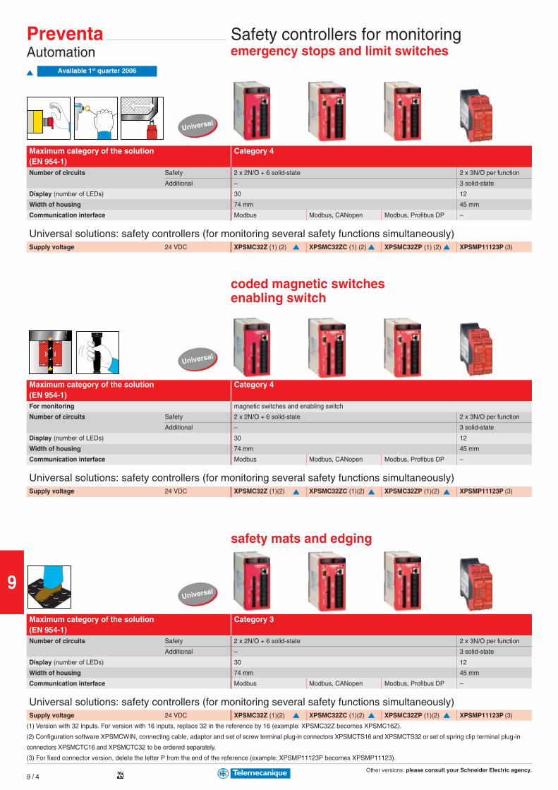
Other versions: please consult your Schneider Electric agency.
9
9 / 4
Universal
Universal
Universal
PreventaAutomation
Safety controllers for monitoringemergency stops and limit switches
Maximum category of the solution Category 4(EN 954-1)Number of circuits Safety 2 x 2N/O + 6 solid-state 2 x 3N/O per function
Additional – 3 solid-state
Display (number of LEDs) 30 12
Width of housing 74 mm 45 mm
Communication interface Modbus Modbus, CANopen Modbus, Profibus DP –
Universal solutions: safety controllers (for monitoring several safety functions simultaneously)Supply voltage 24 VDC XPSMC32Z (1) (2) XPSMC32ZC (1) (2) XPSMC32ZP (1) (2) XPSMP11123P (3)
coded magnetic switchesenabling switch
Maximum category of the solution Category 4(EN 954-1)For monitoring magnetic switches and enabling switch
Number of circuits Safety 2 x 2N/O + 6 solid-state 2 x 3N/O per function
Additional – 3 solid-state
Display (number of LEDs) 30 12
Width of housing 74 mm 45 mm
Communication interface Modbus Modbus, CANopen Modbus, Profibus DP –
Universal solutions: safety controllers (for monitoring several safety functions simultaneously)Supply voltage 24 VDC XPSMC32Z (1)(2) XPSMC32ZC (1)(2) XPSMC32ZP (1)(2) XPSMP11123P (3)
safety mats and edging
Maximum category of the solution Category 3(EN 954-1)Number of circuits Safety 2 x 2N/O + 6 solid-state 2 x 3N/O per function
Additional – 3 solid-state
Display (number of LEDs) 30 12
Width of housing 74 mm 45 mm
Communication interface Modbus Modbus, CANopen Modbus, Profibus DP –
Universal solutions: safety controllers (for monitoring several safety functions simultaneously)Supply voltage 24 VDC XPSMC32Z (1)(2) XPSMC32ZC (1)(2) XPSMC32ZP (1)(2) XPSMP11123P (3)
(1) Version with 32 inputs. For version with 16 inputs, replace 32 in the reference by 16 (example: XPSMC32Z becomes XPSMC16Z).
(2) Configuration software XPSMCWIN, connecting cable, adaptor and set of screw terminal plug-in connectors XPSMCTS16 and XPSMCTS32 or set of spring clip terminal plug-in
connectors XPSMCTC16 and XPSMCTC32 to be ordered separately.
(3) For fixed connector version, delete the letter P from the end of the reference (example: XPSMP11123P becomes XPSMP11123).
Available 1st quarter 2006
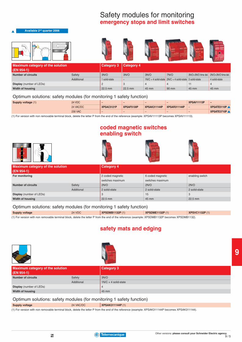
Other versions: please consult your Schneider Electric agency.
9
9 / 5
Maximum category of the solution Category 3 Category 4(EN 954-1)Number of circuits Safety 3N/O 3N/O 3N/O 7N/O 3N/O+3N/O time del. 2N/O+3N/O time del.
Additional 1 solid-state – 1N/C + 4 solid-state 2N/C + 4 solid-state 3 solid-state 4 solid-state
Display (number of LEDs) 2 3 4 4 11 4
Width of housing 22.5 mm 22.5 mm 45 mm 90 mm 45 mm 45 mm
Optimum solutions: safety modules (for monitoring 1 safety function)Supply voltage (1) 24 VDC – – – – XPSAV11113P –
24 VAC/DC XPSAC5121P XPSAF5130P XPSAK311144P XPSAR311144P – XPSATE5110P
230 VAC – – – – – XPSATE3710P
(1) For version with non removable terminal block, delete the letter P from the end of the reference (example: XPSAV11113P becomes XPSAV11113).
coded magnetic switchesenabling switch
Maximum category of the solution Category 4(EN 954-1)For monitoring 2 coded magnetic 6 coded magnetic enabling switch
switches maximum switches maximum
Number of circuits Safety 2N/O 2N/O 2N/O
Additional 2 solid-state 2 solid-state 2 solid-state
Display (number of LEDs) 3 15 3
Width of housing 22.5 mm 45 mm 22.5 mm
Optimum solutions: safety modules (for monitoring 1 safety function)Supply voltage 24 VDC XPSDMB1132P (1) XPSDME1132P (1) XPSVC1132P (1)
(1) For version with non removable terminal block, delete the letter P from the end of the reference (example: XPSDMB1132P becomes XPSDMB1132).
safety mats and edging
Maximum category of the solution Category 3(EN 954-1)Number of circuits Safety 3N/O
Additional 1N/C + 4 solid-state
Display (number of LEDs) 4
Width of housing 45 mm
Optimum solutions: safety modules (for monitoring 1 safety function)Supply voltage 24 VAC/DC XPSAK311144P (1)
(1) For version with non removable terminal block, delete the letter P from the end of the reference (example: XPSAK311144P becomes XPSAK311144).
Safety modules for monitoringemergency stops and limit switches
Available 2nd quarter 2006

Other versions: please consult your Schneider Electric agency.
9
9 / 6
0,0
0,2
0,4
0,6
0,8
1,0
Universal
Universal
Universal
Maximum category of the solution Category 4(EN 954-1)Number of circuits Safety 2 x 2N/O + 6 solid-state
Additional –
Display (number of LEDs) 30
Width of housing 74 mm
Communication interface Modbus Modbus, CANopen Modbus, Profibus DP
Universal solutions: safety controllers (for monitoring several safety functions simultaneously)Supply voltage 24 VDC XPSMC32Z (1)(2) XPSMC32ZC (1)(2) XPSMC32ZP (1)(2)
light curtains
Maximum category of the solution Category 4 2 light curtains
(EN 954-1) monitoring max.
Number of circuits Safety 2 x 2N/O + 6 solid-state 2x3N/O per function 6 PNP solid-state
Additional – 3 solid-state 1 PNP + 1 NPN
Display (number of LEDs) 30 12 14 + double display units
Width of housing 74 mm 45 mm 100 mm
Integral Muting function Yes No Yes
Communication interface Modbus Modbus, CANopen Modbus, Profibus DP
Universal solutions: safety controllers (for monitoring several safety functions simultaneously)Supply voltage 24 VDC XPSMC32Z(1)(2) XPSMC32ZC(1)(2) XPSMC32ZP(1)(2) XPSMP11123P (3) XPSLCM1150 (4)
(1) Version with 32 inputs, for version with 16 inputs, replace 32 in the reference by 16 (example: XPSMC32Z becomes XPSMC16Z).
(3) For version with non removable terminal block, delete the letter P from the end of the reference (example: XPSMP11123P becomes XPSMP11123).
(4) Removable terminal blocks
zero speed, time delay
Maximum category of the solution Category 4(EN 954-1)For monitoring Motor zero speed condition
Number of circuits Safety 2 x 2N/O + 6 solid-state
Additional –
Display (number of LEDs) 30
Width of housing 74 mm
Communication interface Modbus Modbus, CANopen Modbus, Profibus DP
Universal solutions: safety controllers (for monitoring several safety functions simultaneously)Supply voltage 24 VDC XPSMC32Z (5) (2) XPSMC32ZC (5) (2) XPSMC32ZP (5) (2)
(5) Plug-in connector version only.
(2) Configuration software XPSMCWIN, connecting cable, adaptor and set of screw terminal plug-in connectors XPSMCTS16 and XPSMCTS32 or set of spring clip terminal plug-in
connectors XPSMCTC16 and XPSMCTC32 to be ordered separately.
PreventaAutomation
Safety controllers for monitoringtwo-hand control
Available 1st quarter 2006
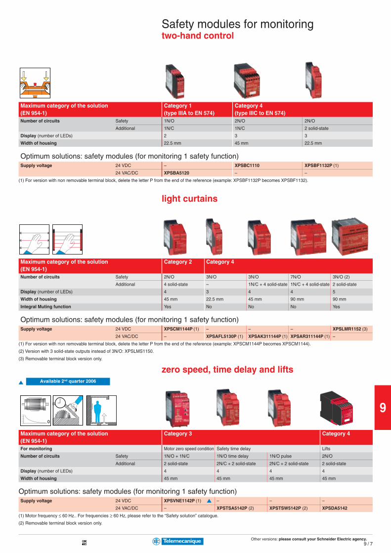
Other versions: please consult your Schneider Electric agency.
9
9 / 7
0,0
0,2
0,4
0,6
0,8
1,0
Safety modules for monitoringtwo-hand control
Maximum category of the solution Category 1 Category 4(EN 954-1) (type IIIA to EN 574) (type IIIC to EN 574)Number of circuits Safety 1N/O 2N/O 2N/O
Additional 1N/C 1N/C 2 solid-state
Display (number of LEDs) 2 3 3
Width of housing 22.5 mm 45 mm 22.5 mm
Optimum solutions: safety modules (for monitoring 1 safety function)Supply voltage 24 VDC – XPSBC1110 XPSBF1132P (1)
24 VAC/DC XPSBA5120 – –
(1) For version with non removable terminal block, delete the letter P from the end of the reference (example: XPSBF1132P becomes XPSBF1132).
light curtains
Maximum category of the solution Category 2 Category 4(EN 954-1)Number of circuits Safety 2N/O 3N/O 3N/O 7N/O 3N/O (2)
Additional 4 solid-state – 1N/C + 4 solid-state 1N/C + 4 solid-state 2 solid-state
Display (number of LEDs) 4 3 4 4 5
Width of housing 45 mm 22.5 mm 45 mm 90 mm 90 mm
Integral Muting function Yes No No No Yes
Optimum solutions: safety modules (for monitoring 1 safety function)Supply voltage 24 VDC XPSCM1144P (1) – – – XPSLMR1152 (3)
24 VAC/DC – XPSAFL5130P (1) XPSAK311144P (1) XPSAR311144P (1) –
(1) For version with non removable terminal block, delete the letter P from the end of the reference (example: XPSCM1144P becomes XPSCM1144).
(2) Version with 3 solid-state outputs instead of 3N/O: XPSLMS1150.
(3) Removable terminal block version only.
zero speed, time delay and lifts
Maximum category of the solution Category 3 Category 4(EN 954-1)For monitoring Motor zero speed condition Safety time delay Lifts
Number of circuits Safety 1N/O + 1N/C 1N/O time delay 1N/O pulse 2N/O
Additional 2 solid-state 2N/C + 2 solid-state 2N/C + 2 solid-state 2 solid-state
Display (number of LEDs) 4 4 4 4
Width of housing 45 mm 45 mm 45 mm 45 mm
Optimum solutions: safety modules (for monitoring 1 safety function)Supply voltage 24 VDC XPSVNE1142P (1) – – –
24 VAC/DC – XPSTSA5142P (2) XPSTSW5142P (2) XPSDA5142
(1) Motor frequency ≤ 60 Hz.. For frequencies ≥ 60 Hz, please refer to the “Safety solution” catalogue.
(2) Removable terminal block version only.
Available 2nd quarter 2006
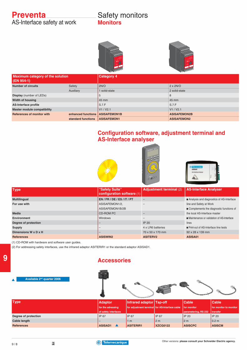
Other versions: please consult your Schneider Electric agency.
9
9 / 8
PreventaAS-Interface safety at work
Safety monitorsMonitors
Configuration software, adjustment terminal andAS-Interface analyser
Maximum category of the solution Category 4(EN 954-1)Number of circuits Safety
Auxiliary
Display (number of LEDs)
Width of housing
AS-Interface profile
Master module compatibility
References of monitor with enhanced functions
standard functions
2N/O 2 x 2N/O
1 solid-state 2 solid-state
5 8
45 mm 45 mm
S.7.F S.7.F
V1 / V2.1 V1 / V2.1
ASISAFEMON1B ASISAFEMON2B
ASISAFEMON1 ASISAFEMON2
Type
Multilingual
For use with
Media
Environment
Degree of protection
Supply
Dimensions W x D x H
References
(1) CD-ROM with hardware and software user guides.
(2) For addressing safety interfaces, use the infrared adaptor ASITERIR1 or the standard adaptor ASISAD1.
Accessories
Adaptor Infrared adaptor Tap-off Cable Cablefor the adressing for adjustment terminal for AS-Interface cable for monitor for monitor to monitor
of safety interfaces parametering, RS 232 transfer
Type
Degree of protection
Cable length
References
IP 67 IP 67 IP 67 IP 20 IP 20
– 1 m 2 m 2 m 0.2 m
ASISAD1 ASITERIR1 XZCG0122 ASISCPC ASISCM
“Safety Suite” Adjustment terminal (2) AS-Interface Analyserconfiguration software (1)
EN / FR / DE / ES / IT / PT – b Analysis and diagnostics of AS-Interface
ASISAFEMON1/2, – line and Safety at Work
ASISAFEMON1B/2B b Complements the diagnostic functions of
CD-ROM PC – the local AS-Interface master
Windows – b Maintenance or validation of AS-Interface
– IP 20 lines
– 4 x LR6 batteries b Print-out of AS-Interface line tests
– 70 x 50 x 170 mm 92 x 28 x 139 mm
ASISWIN2 ASITERV2 ASISA01
Available 2nd quarter 2006
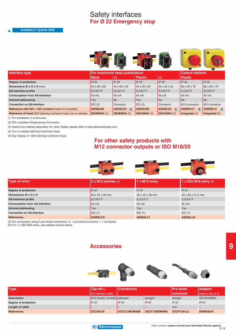
Other versions: please consult your Schneider Electric agency.
9
9 / 9
Type
Description
Degree of protection
Length of cable
References
Accessories
(5) For connection using 2 pre-wired connectors, or 1 pre-wired connector + 1 connector.(6) For 1 x ISO M20 entry, use adaptor shown below.
2 x M12 entries (5) 1 x M12 entry 1 x ISO M16 entry (6)Type of entry
Degree of protection
Dimensions W x D x H
AS-Interface profile
Consumption from AS-Interface
Infrared addressing
Connection on AS-Interface
References
IP 67 IP 67 IP 67
40 x 40 x 58 mm 40 x 40 x 58 mm 40 x 40 x 57.5 mm
S.0.B.F.F S.0.B.F.F S.0.B.F.F
45 mA 45 mA 45 mA
Yes Yes Yes
IDC (1) IDC (1) IDC (1)
ASISSLC2 ASISSLC1 ASISSLLS
Safety interfacesFor Ø 22 Emergency stop
Interface type For mushroom head pushbuttons Control stationsMetal (1) Plastic (1) Plastic
Degree of protection IP 20 IP 20 IP 20 IP 20 IP 65 IP 65
Dimensions W x D x H (mm) 40 x 90 x 68 40 x 80 x 40 40 x 90 x 64 40 x 90 x 40 66 x 95 x 78 66 x 95 x 78
AS-Interface profile S.0.B.F.F S.0.B.F.F S.0.B.F.F S.0.B.F.F S.0.B.F.F S.0.B.F.F
Consumption from AS-Interface 45 mA 45 mA 45 mA 45 mA 45 mA 45 mA
Infrared addressing Yes No Yes No No No
Connection on AS-Interface IDC (2) Connector IDC (2) Connector M12 connector M12 connector
Reference with N/C + N/C contact (head not included) ASISSLB4 ASISSLE4 ASISSLB5 ASISSLE5 ASISEA1C ASISEK1C
Reference of head (Ø40 latching mushroom head, turn to release) ZB4BS844 (3) ZB4BS844 (3) ZB4AS844 (3) ZB4AS844 (3) Integrated (4) Integrated (5)
(1) For installation in enclosures.
(2) IDC: Insulation Displacement Connector.
(3) Head to be ordered separately. For other heads, please refer to www.telemecanique.com.
(4) Turn to release latching mushroom head.
(5) Key release (n° 455) latching mushroom head.
For other safety products withM12 connector outputs or ISO M16/20
Tap-off for Connectors Pre-wired AdaptorAS-Interface cable connector (sold in lots of 5)
M12 female, threaded elbowed straight straight ISO M16/M20
IP 67 IP 67 IP 67 IP 67 IP 67
– – – 2 m –
XZCG0120 XZCC12MCM40B XZCC12MDM40B XZCP1541L2 DE9RI2016
Available 2nd quarter 2006
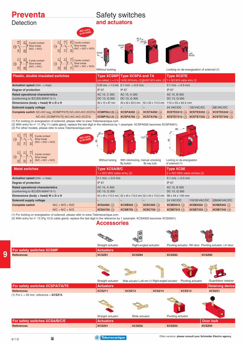
Other versions: please consult your Schneider Electric agency.
9
9 / 1 0
1314 22
21
1112 22
21
20/22
20/2240,3
20/22
95
88
60
30
ISO entry
(to EN 50262)
ISO entry
(to EN 50262)
20/22
Actuation speed (min → max)
Degree of protection
Rated operational characteristics(conforming to IEC/EN 60947-5-1)
Dimensions (body + head) W x D x H
Solenoid supply voltage
Complete switch N/C+N/O stag. (XCSMP/PA/TE) N/C+N/O+N/O (XCSTA)
N/C+N/C (XCSMP/PA/TE) N/C+N/C+N/O (XCSTA)
Type XCSMP Type XCSPA and TA Type XCSTEpre-cabled, L = 2 m 1xISO M16 etry. (2) 2xISO M16 entrs. (2) 1 x ISO M16 cable entry (2)
0.05 m/s → 1.5 m/s 0.1 m/s → 0.5 m/s 0.1 m/s → 0.5 m/s
IP 67 IP 67 IP 67
AC 15, C 300 AC 15, A 300 AC 15, B 300DC 13, Q 300 DC 13, Q 300 DC 13, Q 300
30 x 15 x 87 mm 30 x 30 x 93.5 mm 52 x 30 x 114.5 mm 110 x 33 x 93.5 mm
– – – 24 VAC/DC 120 VAC/DC 230 VAC/DC
XCSMP59L2 (3) XCSPA592 XCSTA592 XCSTE5312 XCSTE5332 XCSTE5342
XCSMP79L2 (3) XCSPA792 XCSTA792 XCSTE7312 XCSTE7332 XCSTE7342
2-pole contactSlow break(N/C + N/O)
2-pole contactSlow break(N/C + N/C)
3-pole contactSlow break(N/C + N/O + N/O)
3-pole contactSlow break(N/C + N/C + N/O)
PreventaDetection
Safety switchesand actuators
Plastic, double insulated switches
Without locking Locking on de-energisation of solenoid (1)
3-pole contactSlow break(N/C + N/O + N/O)
3-pole contactSlow break(N/C + N/C + N/O) Without locking With interlocking, manual unlocking
By button By key lockLocking on de-energisationof solenoid (1)
(1) For locking on energisation of solenoid, please refer to www.Telemecanique.com.(2) With entry for n° 11 (Pg 11) cable gland, replace the last digit in the reference by 1 (example: XCSPA592 becomes XCSPA591).(3) For other models, please refer to www.Telemecanique.com.
Actuation speed (min → max)
Degree of protection
Rated operational characteristics(conforming to IEC/EN 60947-5-1)
Dimensions (body + head) W x D x H
Solenoid supply voltage
Complete switch N/C + N/O + N/O
N/C + N/C + N/O
Type XCSA/B/C Type XCSE1 x ISO M20 cable entry (2) 2 x ISO M20 cable entries (2)
0.1 m/s → 0.5 m/s 0.1 m/s → 0.5 m/s
IP 67 IP 67
AC 15, A 300 AC 15, B 300DC 13, Q 300 DC 13, Q 300
40 x 44 x 113.5 mm 52 x 44 x 113.5 mm 52 x 44 x 113.5 mm 98 x 44 x 146 mm
– – – 24 VAC/DC 110/120 VAC/DC 220/240 VAC/DC
XCSA502 XCSB502 XCSC502 XCSE5312 XCSE5332 XCSE5342
XCSA702 XCSB702 XCSC702 XCSE7312 XCSE7332 XCSE7342
Metal switches
(1) For locking on energisation of solenoid, please refer to www.Telemecanique.com.
Accessories(2) With entry for n° 13 (Pg 13.5) cable gland, replace the last digit in the reference by 1 (example: XCSA502 becomes XCSA501).
Straight actuator Wide actuator L=40 mm (1) Right-angled actuator Pivoting actuator
Actuators Retaining device
Straight actuator Right-angled actuator
References
ActuatorsXCSZ81 XCSZ84 XCSZ83 XCSZ85
For safety switches XCSMPPivoting actuator, RH door Pivoting actuator, LH door
Guard/door retainer
Straight actuator Wide actuator Pivoting actuator
References XCSZ11 XCSZ12 XCSZ14 XCSZ13 XCSZ21
For safety switches XCSPA/TA/TE
(1) For L = 29 mm, reference = XCSZ15.
References
Actuators Door lockXCSZ01 XCSZ02 XCSZ03 XCSZ05
For safety switches XCSA/B/C/E
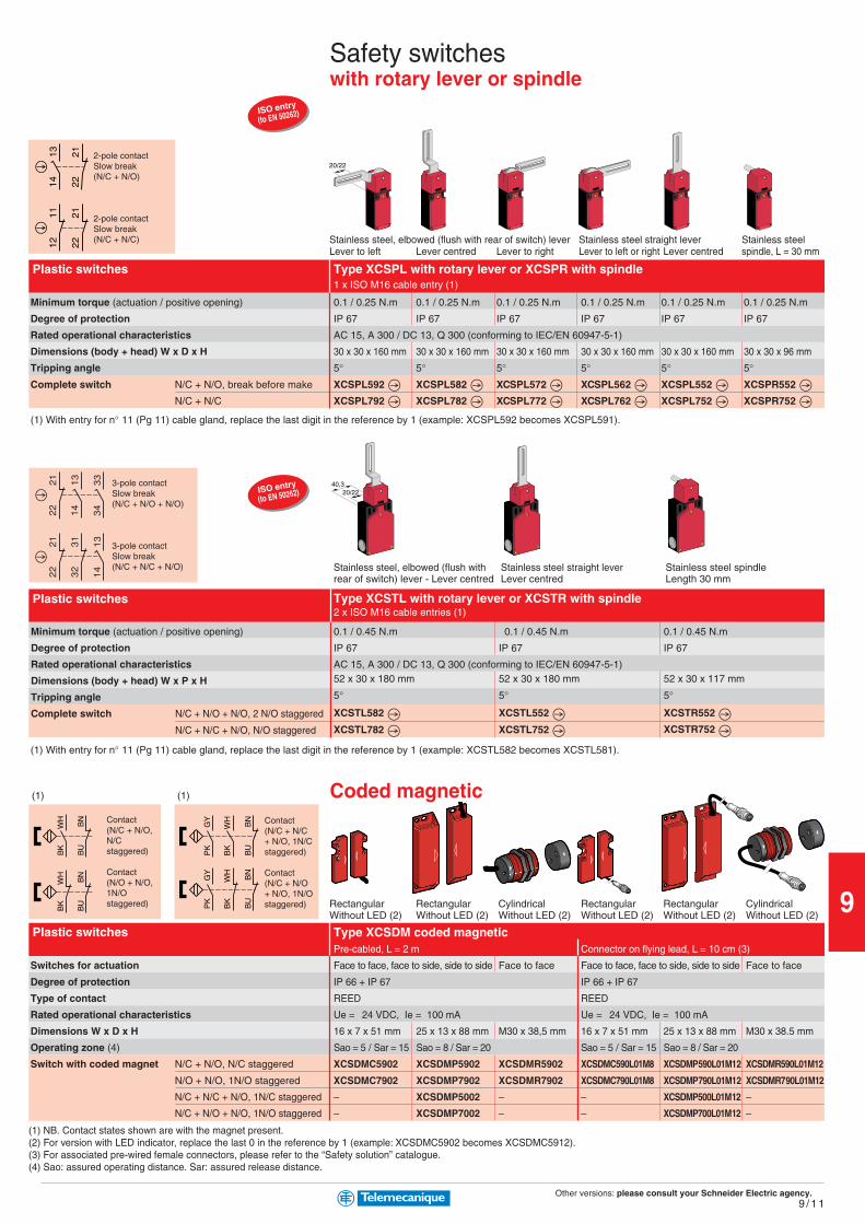
Other versions: please consult your Schneider Electric agency.
9
9 / 1 1
1314 22
21
1112 22
21
20/22
20/2240,3
BK
BU
WH
BN
BK
BU
WH
BN
PK
GY
BK
WH
BU
BN
PK
GY
BK
WH
BU
BN
ISO entry
(to EN 50262)
ISO entry
(to EN 50262)
2-pole contactSlow break(N/C + N/O)
2-pole contactSlow break(N/C + N/C)
Safety switcheswith rotary lever or spindle
Stainless steel, elbowed (flush with rear of switch) lever Stainless steel straight lever Stainless steelLever to left Lever centred Lever to right Lever to left or right Lever centred spindle, L = 30 mm
Minimum torque (actuation / positive opening)
Degree of protection
Rated operational characteristics
Dimensions (body + head) W x D x H
Tripping angle
Complete switch N/C + N/O, break before make
N/C + N/C
Type XCSPL with rotary lever or XCSPR with spindle1 x ISO M16 cable entry (1)
0.1 / 0.25 N.m 0.1 / 0.25 N.m 0.1 / 0.25 N.m 0.1 / 0.25 N.m 0.1 / 0.25 N.m 0.1 / 0.25 N.m
IP 67 IP 67 IP 67 IP 67 IP 67 IP 67
AC 15, A 300 / DC 13, Q 300 (conforming to IEC/EN 60947-5-1)
30 x 30 x 160 mm 30 x 30 x 160 mm 30 x 30 x 160 mm 30 x 30 x 160 mm 30 x 30 x 160 mm 30 x 30 x 96 mm
5° 5° 5° 5° 5° 5°XCSPL592 XCSPL582 XCSPL572 XCSPL562 XCSPL552 XCSPR552
XCSPL792 XCSPL782 XCSPL772 XCSPL762 XCSPL752 XCSPR752
Plastic switches
3-pole contactSlow break(N/C + N/O + N/O)
3-pole contactSlow break(N/C + N/C + N/O) Stainless steel, elbowed (flush with Stainless steel straight lever Stainless steel spindle
rear of switch) lever - Lever centred Lever centred Length 30 mm
Minimum torque (actuation / positive opening)
Degree of protection
Rated operational characteristics
Dimensions (body + head) W x P x H
Tripping angle
Complete switch N/C + N/O + N/O, 2 N/O staggered
N/C + N/C + N/O, N/O staggered
Type XCSTL with rotary lever or XCSTR with spindle2 x ISO M16 cable entries (1)
0.1 / 0.45 N.m 0.1 / 0.45 N.m 0.1 / 0.45 N.m
IP 67 IP 67 IP 67
AC 15, A 300 / DC 13, Q 300 (conforming to IEC/EN 60947-5-1)52 x 30 x 180 mm 52 x 30 x 180 mm 52 x 30 x 117 mm
5° 5° 5°
XCSTL582 XCSTL552 XCSTR552
XCSTL782 XCSTL752 XCSTR752
(1) With entry for n° 11 (Pg 11) cable gland, replace the last digit in the reference by 1 (example: XCSPL592 becomes XCSPL591).
Plastic switches
(1) With entry for n° 11 (Pg 11) cable gland, replace the last digit in the reference by 1 (example: XCSTL582 becomes XCSTL581).
Rectangular Rectangular Cylindrical Rectangular Rectangular CylindricalWithout LED (2) Without LED (2) Without LED (2) Without LED (2) Without LED (2) Without LED (2)
Coded magnetic
Switches for actuation
Degree of protection
Type of contact
Rated operational characteristics
Dimensions W x D x H
Operating zone (4)
Switch with coded magnet N/C + N/O, N/C staggered
N/O + N/O, 1N/O staggered
N/C + N/C + N/O, 1N/C staggered
N/C + N/O + N/O, 1N/O staggered
Type XCSDM coded magneticPre-cabled, L = 2 m Connector on flying lead, L = 10 cm (3)
Face to face, face to side, side to side Face to face Face to face, face to side, side to side Face to face
IP 66 + IP 67 IP 66 + IP 67
REED REED
Ue = 24 VDC, Ie = 100 mA Ue = 24 VDC, Ie = 100 mA
16 x 7 x 51 mm 25 x 13 x 88 mm M30 x 38,5 mm 16 x 7 x 51 mm 25 x 13 x 88 mm M30 x 38.5 mm
Sao = 5 / Sar = 15 Sao = 8 / Sar = 20 Sao = 5 / Sar = 15 Sao = 8 / Sar = 20
XCSDMC5902 XCSDMP5902 XCSDMR5902 XCSDMC590L01M8 XCSDMP590L01M12 XCSDMR590L01M12
XCSDMC7902 XCSDMP7902 XCSDMR7902 XCSDMC790L01M8 XCSDMP790L01M12 XCSDMR790L01M12
– XCSDMP5002 – – XCSDMP500L01M12 –
– XCSDMP7002 – – XCSDMP700L01M12 –
Contact(N/C + N/O,N/Cstaggered)
Contact(N/O + N/O,1N/Ostaggered)
Contact(N/C + N/C+ N/O, 1N/Cstaggered)
Contact(N/C + N/O+ N/O, 1N/Ostaggered)
Plastic switches
(1) NB. Contact states shown are with the magnet present.(2) For version with LED indicator, replace the last 0 in the reference by 1 (example: XCSDMC5902 becomes XCSDMC5912).(3) For associated pre-wired female connectors, please refer to the “Safety solution” catalogue.(4) Sao: assured operating distance. Sar: assured release distance.
(1) (1)
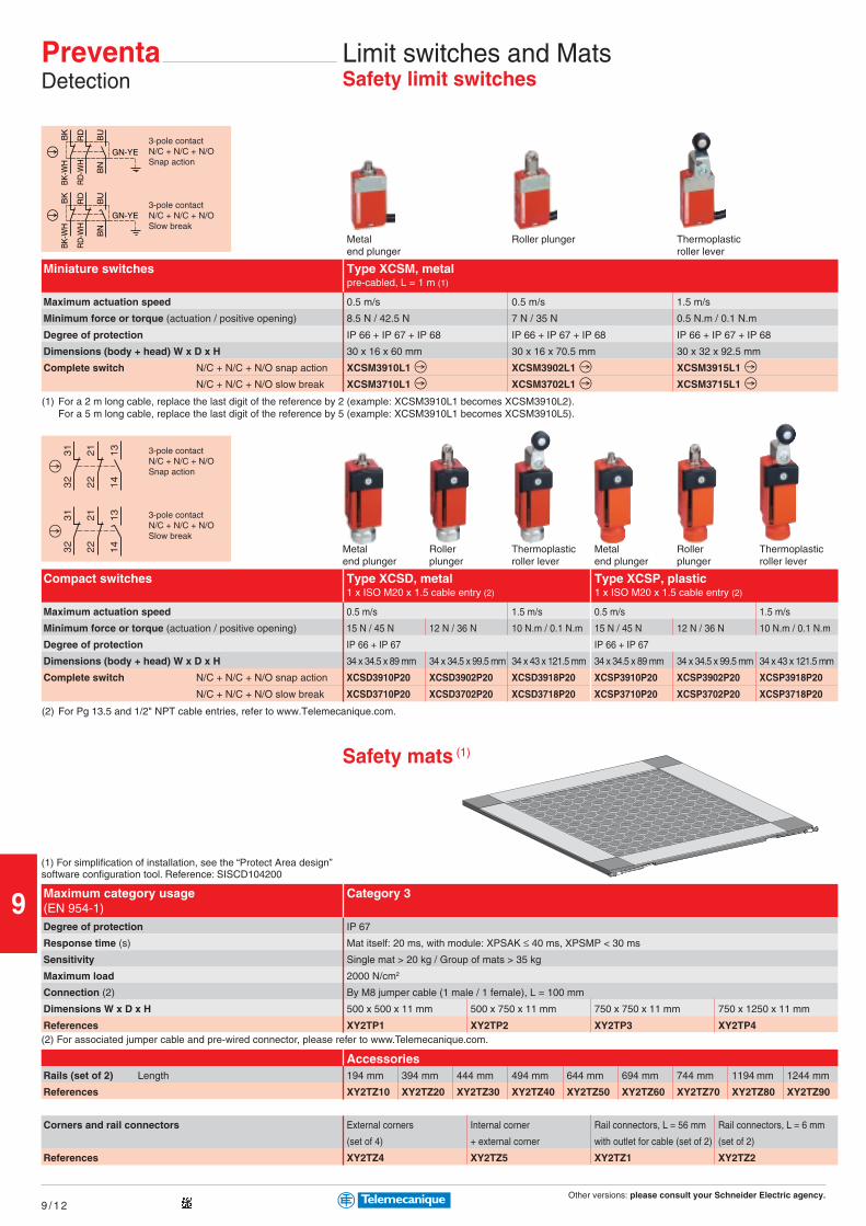
Other versions: please consult your Schneider Electric agency.
9
9 / 1 2
RD
-WH
RD
BU
BN
GN-YE
BK
-WH
BK
RD
-WH
RD
BU
BN
GN-YE
BK
-WH
BK
PreventaDetection
Limit switches and MatsSafety limit switches
3-pole contactN/C + N/C + N/OSlow break
3-pole contactN/C + N/C + N/OSnap action
Type XCSM, metalpre-cabled, L = 1 m (1)
Maximum actuation speed
Minimum force or torque (actuation / positive opening)
Degree of protection
Dimensions (body + head) W x D x H
Complete switch N/C + N/C + N/O snap action
N/C + N/C + N/O slow break
0.5 m/s 0.5 m/s 1.5 m/s
8.5 N / 42.5 N 7 N / 35 N 0.5 N.m / 0.1 N.m
IP 66 + IP 67 + IP 68 IP 66 + IP 67 + IP 68 IP 66 + IP 67 + IP 68
30 x 16 x 60 mm 30 x 16 x 70.5 mm 30 x 32 x 92.5 mm
XCSM3910L1 XCSM3902L1 XCSM3915L1
XCSM3710L1 XCSM3702L1 XCSM3715L1
AccessoriesRails (set of 2) Length
References
Corners and rail connectors
References
194 mm 394 mm 444 mm 494 mm 644 mm 694 mm 744 mm 1194 mm 1244 mm
XY2TZ10 XY2TZ20 XY2TZ30 XY2TZ40 XY2TZ50 XY2TZ60 XY2TZ70 XY2TZ80 XY2TZ90
External corners Internal corner Rail connectors, L = 56 mm Rail connectors, L = 6 mm
(set of 4) + external corner with outlet for cable (set of 2) (set of 2)
XY2TZ4 XY2TZ5 XY2TZ1 XY2TZ2
(2) For associated jumper cable and pre-wired connector, please refer to www.Telemecanique.com.
Category 3
(1) For simplification of installation, see the “Protect Area design”software configuration tool. Reference: SISCD104200
Maximum category usage(EN 954-1)Degree of protection
Response time (s)
Sensitivity
Maximum load
Connection (2)
Dimensions W x D x H
References
IP 67
Mat itself: 20 ms, with module: XPSAK ≤ 40 ms, XPSMP < 30 ms
Single mat > 20 kg / Group of mats > 35 kg
2000 N/cm2
By M8 jumper cable (1 male / 1 female), L = 100 mm
500 x 500 x 11 mm 500 x 750 x 11 mm 750 x 750 x 11 mm 750 x 1250 x 11 mm
XY2TP1 XY2TP2 XY2TP3 XY2TP4
(1) For a 2 m long cable, replace the last digit of the reference by 2 (example: XCSM3910L1 becomes XCSM3910L2).For a 5 m long cable, replace the last digit of the reference by 5 (example: XCSM3910L1 becomes XCSM3910L5).
Miniature switches
3-pole contactN/C + N/C + N/OSlow break
3-pole contactN/C + N/C + N/OSnap action
Type XCSD, metal Type XCSP, plastic1 x ISO M20 x 1.5 cable entry (2) 1 x ISO M20 x 1.5 cable entry (2)
Maximum actuation speed
Minimum force or torque (actuation / positive opening)
Degree of protection
Dimensions (body + head) W x D x H
Complete switch N/C + N/C + N/O snap action
N/C + N/C + N/O slow break
0.5 m/s 1.5 m/s 0.5 m/s 1.5 m/s
15 N / 45 N 12 N / 36 N 10 N.m / 0.1 N.m 15 N / 45 N 12 N / 36 N 10 N.m / 0.1 N.m
IP 66 + IP 67 IP 66 + IP 67
34 x 34.5 x 89 mm 34 x 34.5 x 99.5 mm 34 x 43 x 121.5 mm 34 x 34.5 x 89 mm 34 x 34.5 x 99.5 mm 34 x 43 x 121.5 mm
XCSD3910P20 XCSD3902P20 XCSD3918P20 XCSP3910P20 XCSP3902P20 XCSP3918P20
XCSD3710P20 XCSD3702P20 XCSD3718P20 XCSP3710P20 XCSP3702P20 XCSP3718P20
(2) For Pg 13.5 and 1/2" NPT cable entries, refer to www.Telemecanique.com.
Compact switches
Metal Roller plunger Thermoplasticend plunger roller lever
Metal Roller Thermoplastic Metal Roller Thermoplasticend plunger plunger roller lever end plunger plunger roller lever
Safety mats (1)

Other versions: please consult your Schneider Electric agency.
9
9 / 1 3
Light curtainsType 2 conforming to IEC/EN 61496-1
Light curtain
Height protected (conforming to prEN 999)
Nominal sensing distance (Sn)
Number of circuits Safety
Additional
Response time
Modules (integral muting function) 24 VDC
Thru-beam pairs, Pre-cabled, L = 5m PNP
axially aligned M12 connector PNP
Single-beam, infrared transmission
750 ... 1200 mm (1 to 4 beams)
8 m
2N/O
4 solid-state
< 25 ms
XPSCM1144P (1)
XU2S18PP340L5 (2)
XU2S18PP340D (2)
(2) For alignment at 90° to the mounting axes, insert the letter W in the reference before the last letter (example: XU2S18PP340L5 becomes XU2S18PP340WL5).(1) For version with non removable terminal block, delete the letter P from the end of the reference (example: XPSCM1144P becomes XPSCM1144).
AccessoriesCable length
Pre-wired connector for XUSLT for receiver(screened cable) for transmitter
XUSLM for receiver
for transmitter
3 m 5 m 10 m 15 m 30 m
– XSZTCR05 XSZTCR10 XSZTCR15 XSZTCR30
– XSZTCT05 XSZTCT10 XSZTCT15 XSZTCT30
XSZMCR03 – XSZMCR10 – XSZMCR30
XSZMCT03 – XSZMCT10 – XSZMCT30
Type 4 conforming to IEC/EN 61496-1 (3)
Light curtain functions• Auto/Manual,• Monitoring of external switching devices (EDM: External Devices Monitoring),• Test input (MTS: Monitoring Test Signal, XUSLT only),• Blanking (ECS/B),• Floating Blanking (FB),• Blanking + Floating Blanking,• Alignment aid by LED display of each light beam broken,• LED display of operating modes and alarms.
Nominal sensing distance (Sn)
Detection capacity
Number of circuits Safety
Auxiliary (alarm)
Response time (depending on model)
Transmitter + receiver Height protected (mm) 260
350
435
520
610
700
870
955
1045
1130
1215
1390
1570
1745
1920
2095
Multi-beam, infrared transmissionCompact Slim0.3…7.5 m 0.3…9 m 0.3…4.5 m 0.3…7 m
14 mm "finger" 30 mm "hand" 14 mm "finger" 30 mm "hand"
2 solid-state PNP 2 solid-state PNP 2 solid-state PNP 2 solid-state PNP
1 solid-state PNP 1 solid-state PNP 1 solid-state PNP/NPN 1 solid-state PNP/NPN
20…40 ms 20…30 ms 7…24 ms 7…15 ms
XUSLTQ6A0260 – XUSLMN6X0150 XUSLMP5X0150 150
XUSLTQ6A0350 XUSLTR5A0350 XUSLMN6X0300 XUSLMP5X0300 300
XUSLTQ6A0435 – XUSLMN6X0450 XUSLMP5X0450 450
XUSLTQ6A0520 XUSLTR5A0520 XUSLMN6X0600 XUSLMP5X0600 600
XUSLTQ6A0610 – XUSLMN6X0750 XUSLMP5X0750 750
XUSLTQ6A0700 XUSLTR5A0700 XUSLMN6X0900 XUSLMP5X0900 900
XUSLTQ6A0870 XUSLTR5A0870 XUSLMN6X1050 XUSLMP5X1050 1050
XUSLTQ6A0955 – XUSLMN6X1200 XUSLMP5X1200 1200
XUSLTQ6A1045 XUSLTR5A1045 XUSLMN6X1350 XUSLMP5X1350 1350
XUSLTQ6A1130 XUSLTR5A1130 XUSLMN6X1500 XUSLMP5X1500 1500
XUSLTQ6A1215 XUSLTR5A1215 XUSLMN6X1650 XUSLMP5X1650 1650
XUSLTQ6A1390 XUSLTR5A1390 XUSLMN6X1800 XUSLMP5X1800 1800
– XUSLTR5A1570
– XUSLTR5A1745
– XUSLTR5A1920
– XUSLTR5A2095
Compact rangeFlying lead with end connector, L = 0.25 m
Hei
ght
prot
ecte
d (m
m)
(1) For simplification of installation, see the “Protect Area design”software configuration tool. Reference: SISCD104200
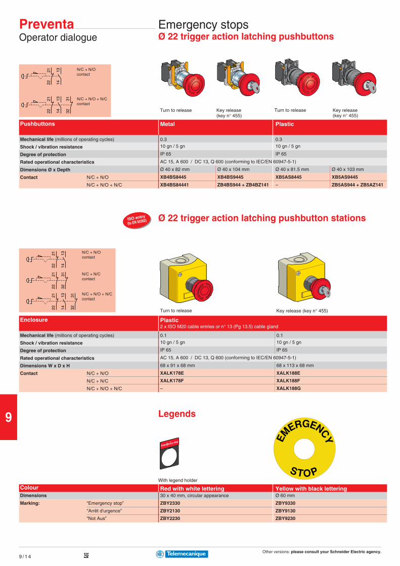
Other versions: please consult your Schneider Electric agency.
9
9 / 1 4
131422
21
131422
21
3231
131422
2122
21
3231
131422
21
3231
ISO entry
(to EN 50262)
Key release(key n° 455)
PreventaOperator dialogue
Emergency stopsØ 22 trigger action latching pushbuttons
Turn to release Turn to releaseKey release(key n° 455)
N/C + N/Ocontact
N/C + N/O + N/Ccontact
Key release (key n° 455)
Legends
Pushbuttons
Mechanical life (millions of operating cycles)
Shock / vibration resistance
Degree of protection
Rated operational characteristics
Dimensions Ø x Depth
Contact N/C + N/O
N/C + N/O + N/C
Metal Plastic
0.3 0.310 gn / 5 gn 10 gn / 5 gn
IP 65 IP 65
AC 15, A 600 / DC 13, Q 600 (conforming to IEC/EN 60947-5-1)
Ø 40 x 82 mm Ø 40 x 104 mm Ø 40 x 81.5 mm Ø 40 x 103 mm
XB4BS8445 XB4BS9445 XB5AS8445 XB5AS9445
XB4BS84441 ZB4BS944 + ZB4BZ141 – ZB5AS944 + ZB5AZ141
Red with white lettering Yellow with black lettering
With legend holder
ColourDimensions
Marking: “Emergency stop”
“Arrêt d'urgence”
“Not Aus”
30 x 40 mm, circular appearance Ø 60 mm
ZBY2330 ZBY9330
ZBY2130 ZBY9130
ZBY2230 ZBY9230
Plastic2 x ISO M20 cable entries or n° 13 (Pg 13.5) cable gland
Turn to release
Ø 22 trigger action latching pushbutton stations
Enclosure
Mechanical life (millions of operating cycles)
Shock / vibration resistance
Degree of protection
Rated operational characteristics
Dimensions W x D x H
Contact N/C + N/O
N/C + N/C
N/C + N/O + N/C
0.1 0.1
10 gn / 5 gn 10 gn / 5 gn
IP 65 IP 65
AC 15, A 600 / DC 13, Q 600 (conforming to IEC/EN 60947-5-1)
68 x 91 x 68 mm 68 x 113 x 68 mm
XALK178E XALK188E
XALK178F XALK188F
– XALK188G
N/C + N/Ocontact
N/C + N/Ccontact
N/C + N/O + N/Ccontact

Other versions: please consult your Schneider Electric agency.
9
9 / 1 5
1211
2221
1211
1413
ISO entry
(to EN 50262)
1211
2221
1211
1413
Emergency stopsCable (tripwire) operated
Latching, without indicator light1 x ISO M20 cable entry (1)
Booted pushbutton reset Key release pushbutton reset (key n° 421)
0.01 0.01
50 gn / 10 gn 50 gn / 10 gn
IP 65 IP 65
AC-15, A300 / DC-13, Q300 (conforming to IEC/EN 60947-5-1)
201 x 71 x 68 mm 201 x 71 x 68 mm
≤ 15 m ≤ 15 m
To right or to left To right or to left
XY2CH13250H29 XY2CH13450H29
XY2CH13270H29 XY2CH13470H29
Mechanical life (millions of operating cycles)
Shock / vibration resistance
Degree of protection
Rated operational characteristics
Dimensions W x D x H
Operating cable length
Operating cable anchoring point
Contact N/C + N/O slow break
N/C + N/C slow break
N/C + N/O contactslow break
N/C + N/C contactslow break
Latching, without indicator light3 x ISO M20 cable entries or n° 13 (Pg 13.5) cable gland
Booted pusbutton reset Key release pushbutton reset (key n° 421)
Mechanical life (millions of operating cycles)
Shock / vibration resistance
Degree of protection
Rated operational characteristics
Dimensions W x D x H
Operating cable length
Operating cable anchoring point
Contact N/C + N/O slow break
N/C + N/C slow break
0.01 0.01
50 gn / 10 gn 50 gn / 10 gn
IP 65 IP 65
AC-15, A300 / DC-13, Q300 (conforming to IEC/EN 60947-5-1)
229 x 82 x 142 mm 229 x 82 x 142 mm
≤ 50 m ≤ 50 m
To left To right To left To right
XY2CE2A250 XY2CE1A250 XY2CE2A450 XY2CE1A450
XY2CE2A270 XY2CE1A270 – XY2CE1A470
For operating cable length ≤ 15 m
For operating cable length ≤ 50 m
(1) With entry for n° 13 (Pg 13.5) cable gland, delete H29 from the end of the reference (example: XY2-CH13250H29 becomes XY2-CH13250).
N/C + N/O contactslow break
N/C + N/C contactslow break
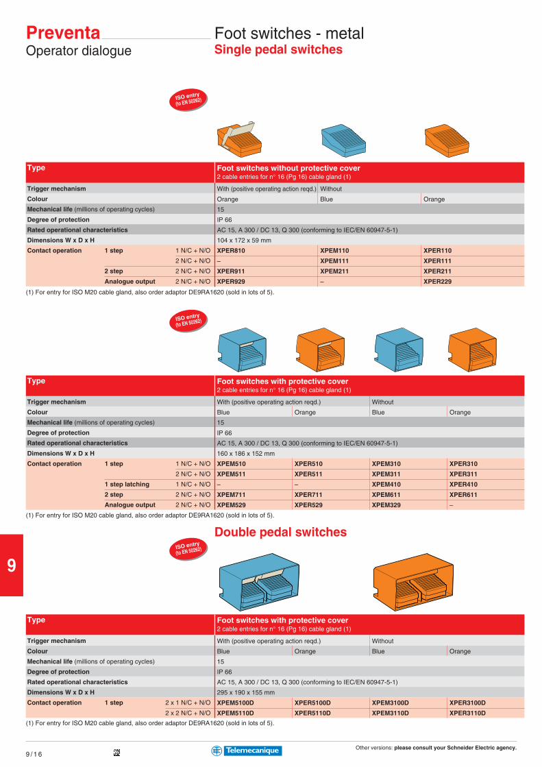
Other versions: please consult your Schneider Electric agency.
9
9 / 1 6
ISO entry
(to EN 50262)
ISO entry
(to EN 50262)
ISO entry
(to EN 50262)
Foot switches - metalSingle pedal switches
PreventaOperator dialogue
Type
Trigger mechanism
Colour
Mechanical life (millions of operating cycles)
Degree of protection
Rated operational characteristics
Dimensions W x D x H
Contact operation 1 step 1 N/C + N/O
2 N/C + N/O
2 step 2 N/C + N/O
Analogue output 2 N/C + N/O
Foot switches without protective cover2 cable entries for n° 16 (Pg 16) cable gland (1)
With (positive operating action reqd.) Without
Orange Blue Orange
15
IP 66
AC 15, A 300 / DC 13, Q 300 (conforming to IEC/EN 60947-5-1)
104 x 172 x 59 mm
XPER810 XPEM110 XPER110
– XPEM111 XPER111
XPER911 XPEM211 XPER211
XPER929 – XPER229
(1) For entry for ISO M20 cable gland, also order adaptor DE9RA1620 (sold in lots of 5).
Foot switches with protective cover2 cable entries for n° 16 (Pg 16) cable gland (1)
With (positive operating action reqd.) Without
Blue Orange Blue Orange
15
IP 66
AC 15, A 300 / DC 13, Q 300 (conforming to IEC/EN 60947-5-1)
160 x 186 x 152 mm
XPEM510 XPER510 XPEM310 XPER310
XPEM511 XPER511 XPEM311 XPER311
– – XPEM410 XPER410
XPEM711 XPER711 XPEM611 XPER611
XPEM529 XPER529 XPEM329 –
Type
Trigger mechanism
Colour
Mechanical life (millions of operating cycles)
Degree of protection
Rated operational characteristics
Dimensions W x D x H
Contact operation 1 step 1 N/C + N/O
2 N/C + N/O
1 step latching 1 N/C + N/O
2 step 2 N/C + N/O
Analogue output 2 N/C + N/O
(1) For entry for ISO M20 cable gland, also order adaptor DE9RA1620 (sold in lots of 5).
Double pedal switches
Foot switches with protective cover2 cable entries for n° 16 (Pg 16) cable gland (1)
With (positive operating action reqd.) Without
Blue Orange Blue Orange
15
IP 66
AC 15, A 300 / DC 13, Q 300 (conforming to IEC/EN 60947-5-1)
295 x 190 x 155 mm
XPEM5100D XPER5100D XPEM3100D XPER3100D
XPEM5110D XPER5110D XPEM3110D XPER3110D
Type
Trigger mechanism
Colour
Mechanical life (millions of operating cycles)
Degree of protection
Rated operational characteristics
Dimensions W x D x H
Contact operation 1 step 2 x 1 N/C + N/O
2 x 2 N/C + N/O
(1) For entry for ISO M20 cable gland, also order adaptor DE9RA1620 (sold in lots of 5).
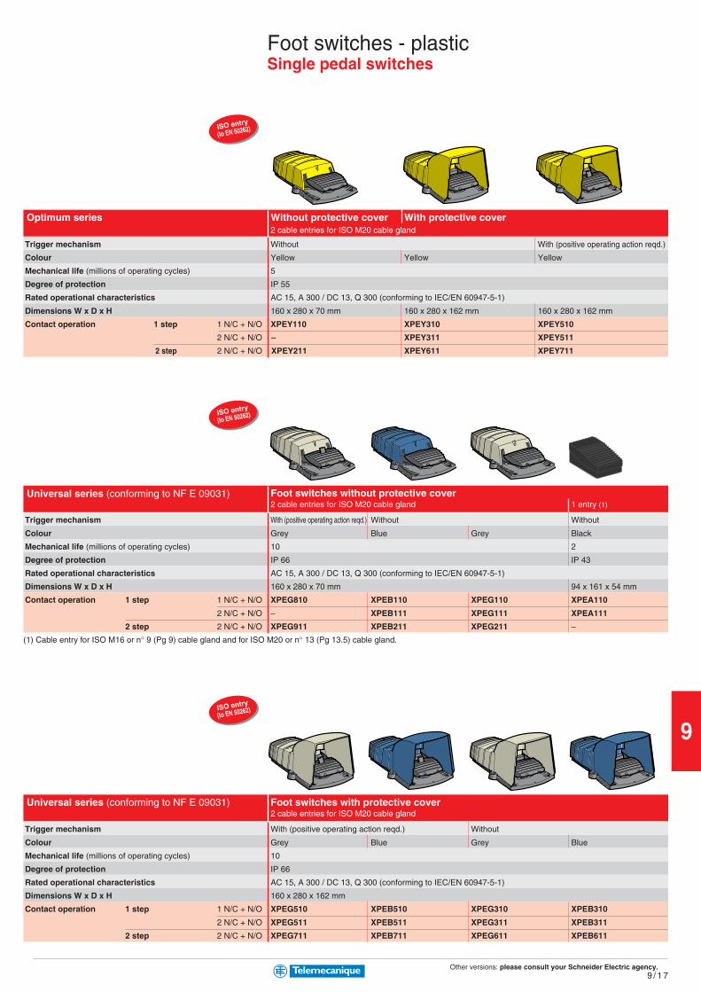
Other versions: please consult your Schneider Electric agency.
9
9 / 1 7
ISO entry
(to EN 50262)
ISO entry
(to EN 50262)
ISO entry
(to EN 50262)
(1) Cable entry for ISO M16 or n° 9 (Pg 9) cable gland and for ISO M20 or n° 13 (Pg 13.5) cable gland.
Foot switches - plasticSingle pedal switches
Trigger mechanism
Colour
Mechanical life (millions of operating cycles)
Degree of protection
Rated operational characteristics
Dimensions W x D x H
Contact operation 1 step 1 N/C + N/O
2 N/C + N/O
2 step 2 N/C + N/O
Foot switches without protective cover2 cable entries for ISO M20 cable gland 1 entry (1)
With (positive operating action reqd.) Without Without
Grey Blue Grey Black
10 2
IP 66 IP 43
AC 15, A 300 / DC 13, Q 300 (conforming to IEC/EN 60947-5-1)
160 x 280 x 70 mm 94 x 161 x 54 mm
XPEG810 XPEB110 XPEG110 XPEA110
– XPEB111 XPEG111 XPEA111
XPEG911 XPEB211 XPEG211 –
Trigger mechanism
Colour
Mechanical life (millions of operating cycles)
Degree of protection
Rated operational characteristics
Dimensions W x D x H
Contact operation 1 step 1 N/C + N/O
2 N/C + N/O
2 step 2 N/C + N/O
Foot switches with protective cover2 cable entries for ISO M20 cable gland
With (positive operating action reqd.) Without
Grey Blue Grey Blue
10
IP 66
AC 15, A 300 / DC 13, Q 300 (conforming to IEC/EN 60947-5-1)
160 x 280 x 162 mm
XPEG510 XPEB510 XPEG310 XPEB310
XPEG511 XPEB511 XPEG311 XPEB311
XPEG711 XPEB711 XPEG611 XPEB611
Trigger mechanism
Colour
Mechanical life (millions of operating cycles)
Degree of protection
Rated operational characteristics
Dimensions W x D x H
Contact operation 1 step 1 N/C + N/O
2 N/C + N/O
2 step 2 N/C + N/O
Without protective cover With protective cover2 cable entries for ISO M20 cable gland
Without With (positive operating action reqd.)
Yellow Yellow Yellow
5
IP 55
AC 15, A 300 / DC 13, Q 300 (conforming to IEC/EN 60947-5-1)
160 x 280 x 70 mm 160 x 280 x 162 mm 160 x 280 x 162 mm
XPEY110 XPEY310 XPEY510
– XPEY311 XPEY511
XPEY211 XPEY611 XPEY711
Optimum series
Universal series (conforming to NF E 09031)
Universal series (conforming to NF E 09031)

Other versions: please consult your Schneider Electric agency.
9
9 / 1 8
ISO entry
(to EN 50262)
0 1 2
1-25-63-4
0 1 2
7 8 (XY2-AU2)
1-25-63-4
PreventaOperator dialogue
Control unitsTwo-hand control
Type
Mechanical life (millions of operating cycles)
Degree of protection
Rated operational characteristics
Dimensions W x D x H
Red emergency stop (N/C + N/C slow break)
Yellow lock out (N/C + N/O break before make)
Two-hand control stations2 cable entries for ISO M20 or n° 13 (Pg 13.5) cable gland, 1 cable entry for n° 21 (Pg 21) cable gland (2)
1 1
IP 65 IP 65
AC 15, A 600 / DC 13, Q 600 (conforming to IEC/EN 60947-5-1)
455 x 170 x 188.5 mm
XY2SB71 (1) XY2SB72 (1)
XY2SB75 XY2SB76
2 control pushbuttons and 1 mushroom headEmergency stop or Lock out pushbutton
(1) To order a two-hand control station with pedestal XY2SB90, add 4 to the end of the reference (example: XY2SB71 becomes XY2SB714).
2 control pushbuttons and 1 mushroom head Emergencystop or Lock out pushbutton, with pre-wired terminal block
Enabling switchContact states
(2) For entry for ISO M25 cable gland, also order adaptor DE9RA2125 + fixing nut DE9EC21 (sold in lots of 5).
Type
Number of contacts
Type of contacts
Description
Shock / vibration resistance
Degree of protection
Rated operational characteristics
Dimensions W x D x H
References
Plastic gripEntry for Ø 7 to 13 mm cable
3 3
2 enabling, 3 positions + 1 N/C 2 enabling, 3 positions + 1 N/C
+ additional 1 N/O contact
Without button With button for N/O contact (auxiliary)
10 gn / 6 gn
IP 66 IP 65
AC 15, C300 / DC 13, R300 (conforming to IEC/EN 60947-5-1)
46 x 58 x 261 mm 46 x 58 x 269 mm
XY2AU1 XY2AU2
For fixing accessories, please refer to www.Telemecanique.com.
Contact closed
Contact open
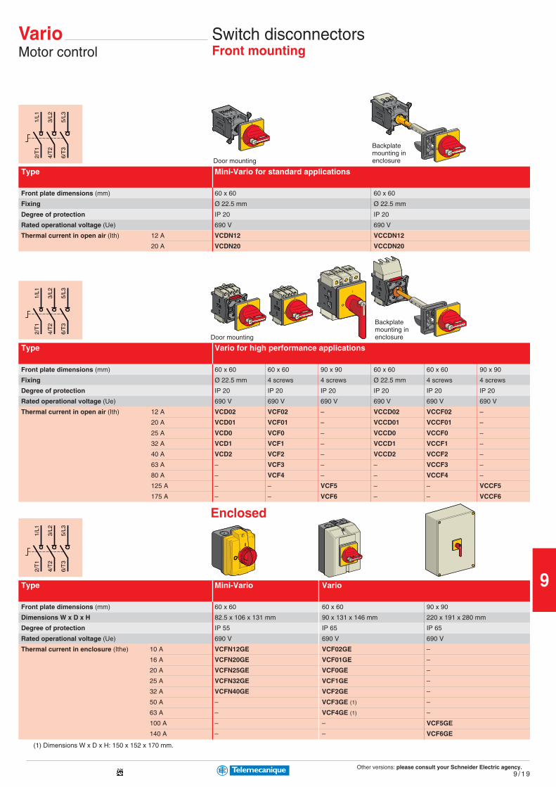
Other versions: please consult your Schneider Electric agency.
9
9 / 1 9
1/L1
2/T
1
3/L2
4/T
2
5/L3
6/T
3
1/L1
2/T
1
3/L2
4/T
2
5/L3
6/T
3
1/L1
2/T
1
3/L2
4/T
2
5/L3
6/T
3
VarioMotor control
Switch disconnectorsFront mounting
Door mounting
Type
Front plate dimensions (mm)
Fixing
Degree of protection
Rated operational voltage (Ue)
Thermal current in open air (Ith) 12 A
20 A
Mini-Vario for standard applications
60 x 60 60 x 60
Ø 22.5 mm Ø 22.5 mm
IP 20 IP 20
690 V 690 V
VCDN12 VCCDN12
VCDN20 VCCDN20
Door mounting
Type
Front plate dimensions (mm)
Fixing
Degree of protection
Rated operational voltage (Ue)
Thermal current in open air (Ith) 12 A
20 A
25 A
32 A
40 A
63 A
80 A
125 A
175 A
Vario for high performance applications
60 x 60 60 x 60 90 x 90 60 x 60 60 x 60 90 x 90
Ø 22.5 mm 4 screws 4 screws Ø 22.5 mm 4 screws 4 screws
IP 20 IP 20 IP 20 IP 20 IP 20 IP 20
690 V 690 V 690 V 690 V 690 V 690 V
VCD02 VCF02 – VCCD02 VCCF02 –
VCD01 VCF01 – VCCD01 VCCF01 –
VCD0 VCF0 – VCCD0 VCCF0 –
VCD1 VCF1 – VCCD1 VCCF1 –
VCD2 VCF2 – VCCD2 VCCF2 –
– VCF3 – – VCCF3 –
– VCF4 – – VCCF4 –
– – VCF5 – – VCCF5
– – VCF6 – – VCCF6
Backplatemounting inenclosure
Type
Front plate dimensions (mm)
Dimensions W x D x H
Degree of protection
Rated operational voltage (Ue)
Thermal current in enclosure (Ithe) 10 A
16 A
20 A
25 A
32 A
50 A
63 A
100 A
140 A
Mini-Vario Vario
60 x 60 60 x 60 90 x 90
82.5 x 106 x 131 mm 90 x 131 x 146 mm 220 x 191 x 280 mm
IP 55 IP 65 IP 65
690 V 690 V 690 V
VCFN12GE VCF02GE –
VCFN20GE VCF01GE –
VCFN25GE VCF0GE –
VCFN32GE VCF1GE –
VCFN40GE VCF2GE –
– VCF3GE (1) –
– VCF4GE (1) –
– – VCF5GE
– – VCF6GE
(1) Dimensions W x D x H: 150 x 152 x 170 mm.
Enclosed
Backplatemounting inenclosure

Other versions: please consult your Schneider Electric agency.
9
9 / 2 0
2/T
1
4/T
2
6/T
3
1/L1
3/L2
5/L3
Motor startersEnclosed thermal-magnetic motor circuit-breakers
Complete circuit-breaker: circuit-breaker+ enclosure + safety device.Ex.: GV2ME01 + GV2MC02 + GV2K04.
Thermal-magnetic motor circuit-breakers
– 0.06 0.09 0.12…0.18 0.25…0.37
0.1…0.16 0.16…0.25 0.25…0.40 0.40…0.63 0.63…1
1.5 2.4 5 8 13
0.16 0.25 0.40 0.63 1
GV2ME01 GV2ME02 GV2ME03 GV2ME04 GV2ME05
0.37…0.55 0.75 1.1…1.5 2.2 3…4
1…1.6 1.6…2.5 2.5…4 4…6.3 6…10
22.5 33.5 51 78 138
1.6 2.5 4 6.3 9
GV2ME06 GV2ME07 GV2ME08 GV2ME10 GV2ME14
5.5 7.5 9…11 11 15
9…14 13…18 17…23 20…25 24…32
170 223 327 327 416
13 17 21 23 24
GV2ME16 GV2ME20 GV2ME21 GV2ME22 GV2ME32
Type
Motor power kW (on 400 V)
Setting range A
Current Id ± 20% A
Current Ithe (in enclosure) A
Reference
Motor power kW (on 400 V)
Setting range A
Current Id ± 20% A
Current Ithe (in enclosure) A
Reference
Motor power kW (on 400 V)
Setting range A
Current Id ± 20% A
Current Ithe (in enclosure) A
Reference
(1) Dimensions with safety device GV2K04 fitted.
Empty enclosure
Surface mounting Flush mounting
IP 55 IP 55 (front face)
93 x 145.5 x 147 mm 93 x 55 x 126 mm
GV2MC02 GV2MP02
Type
Mounting
Degree of protection
Dimensions W x D x H (1)
References
Safety devices
Turn to release Turn to release Key release
Padlockable in “Off” position (key n° 455)
GV2K04 GV2K031 GV2K021
Type
With red mushroom head
References
Enclosure
Safety device
TeSysMotor control

Other versions: please consult your Schneider Electric agency.
9
9 / 2 1
TeSysMotor control
Motor startersEnclosed 3-phase motor starters
Type
Degree of protection
Standard motor power ratings (kW), category AC3 Ith setting
220/230 V 400/415 V 440 V range (A)
– 0.06 0.06 0.16…0.25
0.06 0.09 0.12 0.25…0.40
– 0.18 0.18 0.40…0.63
0.12 0.25 0.25 0.63…1
0.25 0.55 0.55 1…1.6
0.37 0.75 1.1 1.6…2.5
0.75 1.5 1.5 2.5…4
1.1 2.2 3 4…6.3
1.5 4 4 6…10
3 5.5 5.5 9…14
4 7.5 9 13…18
4 9 9 17…23
Type
Degree of protection
Standard motor power ratings (kW), category AC3 Ith setting
380/400 V range (A)
0.06 0.16…0.25
0.09 0.25…0.40
0.18 0.40…0.63
0.25 0.63…1
0.55 1…1.6
0.75 1.6…2.5
1.5 2.5…4
2.2 4…6.3
4 6…10
Non reversing Reversing
IP 657 IP 657
Basic references
(The code Q7 (380/400 V) designates the power supply voltage to which the starter will be connected)
LJ7K06Q702 LJ8K06Q702
LJ7K06Q703 LJ8K06Q703
LJ7K06Q704 LJ8K06Q704
LJ7K06Q705 LJ8K06Q705
LJ7K06Q706 LJ8K06Q706
LJ7K06Q707 LJ8K06Q707
LJ7K06Q708 LJ8K06Q708
LJ7K06Q710 LJ8K06Q710
LJ7K09Q714 LJ8K09Q714
With integral control transformer, 400/24 V With integral control transformer, 400/24 V
The control circuit must be cabled by the user.
Control circuit voltages available
Volts 50/60 Hz
(1) Voltage code
24 V 230 V 400 V 415 V
B7 P7 V7 N7
Non reversing Reversing
IP 657 IP 657 IP 657
Basic reference, to be completed by code indicating voltage (1)
LG1K065pppppppppp02 LG7K06pppppppppp02 LG8K06pppppppppp02
LG1K065pppppppppp03 LG7K06pppppppppp03 LG8K06pppppppppp03
LG1K065pppppppppp04 LG7K06pppppppppp04 LG8K06pppppppppp04
LG1K065pppppppppp05 LG7K06pppppppppp05 LG8K06pppppppppp05
LG1K065pppppppppp06 LG7K06pppppppppp06 LG8K06pppppppppp06
LG1K065pppppppppp07 LG7K06pppppppppp07 LG8K06pppppppppp07
LG1K065pppppppppp08 LG7K06pppppppppp08 LG8K06pppppppppp08
LG1K065pppppppppp10 LG7K06pppppppppp10 LG8K06pppppppppp10
LG1K095pppppppppp14 LG7K09pppppppppp14 LG8K09pppppppppp14
LG1D122pppppppppp16 LG7D12pppppppppp16 LG8K12pppppppppp16
LG1D182pppppppppp20 LG7D18pppppppppp20 –
LG1D182pppppppppp21 LG7D18pppppppppp21 –

ZONE 20
ZONE 22
ZONE 21
Exp
losiv
e A
tmos
pher
es A wide range of productsdesigned to operate inenvironments subject to risks!
A reference for installations in ATEX Dustexplosive atmospheres.
The essentialguideA selection ofcertified products,conforming to theEuropean DirectiveATEX94/9/EC, toensure maximumsafety for yourinstallations in azone where therisk of explosionor fire is high.
What is an explosive atmosphere according to theDirective?It is the mixing with air, in atmospheric conditions, of flammablesubstances in the form of gas, vapour, mist or dust which, in theevent of combustion, spreads throughout the non burning mix.
Implementation of European Directives
b Directive 99/92/EC
This requires that a risk analysis be performed for all industrialprocesses.If there is any risk of an explosion:p the zones are defined and physically identified,p the installation is classified by governing bodies.
b Directive 94/9/EC
This requires certification of the products in accordance with theclassification of the zones of use
b Dust zones
p Zone 20: area where an explosive atmosphere exists in the form ofcombustible clouds of dust in the air, either permanently, for longperiods or frequently.
p Zone 21: area where an explosive atmosphere exists in the form ofcombustible clouds of dust in the air during normal operationoccasionally.
p Zone 22: area where an explosive atmosphere in the form ofcombustible clouds of dust in the air is unlikely to occur during normaloperation but, if it does occur, it is only for a short period.
Main sectors of activity subject to a higher risk ofexplosion or fire
The products inthis catalogueare certified by aEuropean UnionCommissionnotified body.
Flour mills
Wood and aluminiumworkshops
Grain drying areas
Bulk conveying
Bagging
Grain silos
10/0
10/1
10
Contents
Detection pages
b Inductive proximity sensors ............................................. 10/2Universal and Analogue XSb Proximity sensors ................................................ 10/3 and 10/4Rotation monitoring and capacitive XS/XTNamur XSb Intrinsically safe enclosures ............................................. 10/5Processing module NY3b Limit switches ........................................................... 10/6 to 10/9Miniature XCMCompact XCKDClassic XCKMApplication - hoisting, handling and conveyingb Pressure and vacuum switches ................... 10/10 and 10/11Adjustable differential XMLB
Control andsignalling unitsb Pushbuttons and mushroom heads Ø 22 .................. 10/12Harmony XB4b Selector switches and key switches Ø 22.................. 10/13Harmony XB4b Illuminated pushbuttons and pilot lights Ø 22 .......... 10/14Harmony XB4b Control stations ................................................................. 10/15Harmony XAW
Machine safetyb Tripwire operated Emergency stops ............................ 10/16Preventa XY2b Foot switches ..................................................................... 10/16Preventa XPE
Automationb Weighing system ............................................................... 10/17Modicon Premiumb I/O modules ........................................................................ 10/17Modicon Quantum
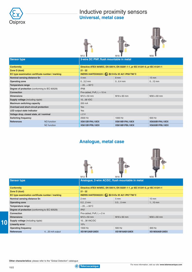
For more information, visit our site: www.telemecanique.com
10/2
10
Inductive proximity sensorsUniversal, metal case
Sensor type 3-wire DC PNP, flush mountable in metal
Conformity Directive ATEX 94/9/EC, EN 50014, EN 50281-1-1, pr IEC 61241-0, pr IEC 61241-1
Zone D (dust) 21 - 22
EC type examination certificate number / marking INERIS 04ATEX0022X / D-Ex tD A21 IP68 T90°CNominal sensing distance Sn 4 mm 8 mm 15 mm
Operating zone 0...3.2 mm 0...6.4 mm 0...12 mm
Temperature range – 20...+ 60°CDegree of protection (conforming to IEC 60529) IP68
Connection Pre-cabled, PvR, L = 10 m
Dimensions M12 x 50 mm M18 x 60 mm M30 x 60 mm
Supply voltage (including ripple) 10...58 VDC
Maximum switching capacity 200 mA
Overload and short-circuit protection Yes
LED output state indicator Yes
Voltage drop, closed state, at I nominal ≤ 2 V
Switching frequency 2500 Hz 1000 Hz 500 Hz
References NO function XS612B1PAL10EX XS618B1PAL10EX XS630B1PAL10EX
NC function XS612B1PBL10EX XS618B1PBL10EX XS630B1PBL10EX
Analogue, metal case
M12 M18 M30
Sensor type Analogue, 2-wire AC/DC, flush mountable in metal
Conformity Directive ATEX 94/9/EC, EN 50014, EN 50281-1-1, pr IEC 61241-0, pr IEC 61241-1
Zone D (dust) 21 - 22
EC type examination certificate number / marking INERIS 04ATEX0022X / D-Ex tD A21 IP67 T90°CNominal sensing distance Sn 2 mm 5 mm 10 mm
Operating zone 0.2...2 mm 0.5…5 mm 1...10 mm
Temperature range – 20...+ 60°CDegree of protection (conforming to IEC 60529) IP67
Connection Pre-cabled, PvR, L = 2 m
Dimensions M12 x 50 mm M18 x 60 mm M30 x 60 mm
Supply voltage (including ripple) 10…38 VAC/DC
Linearity error 10%
Operating frequency 1500 Hz 500 Hz 300 Hz
References 4…20 mA output XS1M12AB120EX XS1M18AB120EX XS1M30AB120EX
Other characteristics: please refer to the “Global Detection” catalogue
Osiprox
M12 M18 M30

For more information, visit our site: www.telemecanique.com
10/3
10
Sensor type 3-wire DC PNP, flush mountable in metal
Conformity Directive ATEX 94/9/EC, EN 50014, EN 50281-1-1, pr IEC 61241-0, pr IEC 61241-1
Zone D (dust) 21 - 22
EC type examination certificate number / marking INERIS 04ATEX0022X / D-Ex tD A21 IP67 T90°CNominal sensing distance Sn 10 mm
Operating zone 0…8 mm
Temperature range – 20...+ 60°CDegree of protection (conforming to IEC 60529) IP67
Connection Pre-cabled, PvR, L = 2 m
Dimensions M30 x 81 mm
Supply voltage (including ripple) 10...58 VDC
Maximum switching capacity 200 mA
Overload and short-circuit protection Yes
LED output state indicator Yes
Voltage drop, closed state, at I nominal ≤ 2 V
Version Slow Fast
Maximum speed of passing object 6000 impulses/minute 48,000 impulses/minute
Adjustable frequency range 6…150 impulses/minute 120…3000 impulses/minute
References NC function XSAV11373EX XSAV12373EX
Capacitive, metal case
M18 M30
Sensor type 3-wire DC PNP, flush mountable in metal
Conformity Directive ATEX 94/9/EC, EN 50014, EN 50281-1-1, pr IEC 61241-0, pr IEC 61241-1
Zone D (dust) 21 - 22
EC type examination certificate number / marking INERIS 04ATEX0022X / D-Ex tD A21 IP67 T90°CNominal sensing distance Sn 5 mm 10 mm
Operating zone 0…3.6 mm 0…7.2 mm
Temperature range – 20...+ 60°CDegree of protection (conforming to IEC 60529) IP67
Connection Pre-cabled, PVC, L = 2 m
Dimensions M18 x 60 mm M30 x 60 mm
Supply voltage (including ripple) 10…38 VDC
Maximum switching capacity 300 mA
Overload and short-circuit protection Yes
LED output state indicator Yes
Voltage drop, closed state, at I nominal ≤ 2 V
Switching frequency 100 Hz
References NO function XT1M18PA372EX XT1M30PA372EX
NC function XT1M18PB372EX XT1M30PB372EX
Other characteristics: please refer to the “Global Detection” catalogue
Proximity sensorsRotation monitoring, metal case
M30
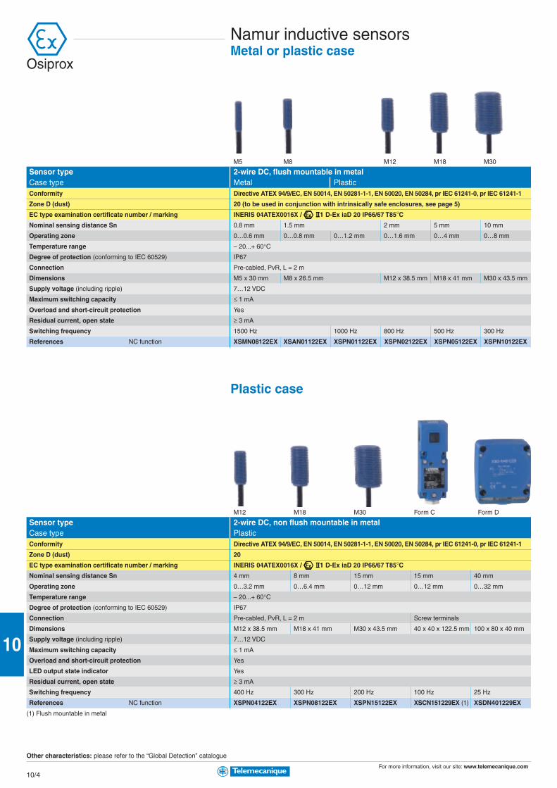
For more information, visit our site: www.telemecanique.com
10/4
10
Namur inductive sensorsMetal or plastic case
Sensor type 2-wire DC, flush mountable in metalCase type Metal PlasticConformity Directive ATEX 94/9/EC, EN 50014, EN 50281-1-1, EN 50020, EN 50284, pr IEC 61241-0, pr IEC 61241-1
Zone D (dust) 20 (to be used in conjunction with intrinsically safe enclosures, see page 5)
EC type examination certificate number / marking INERIS 04ATEX0016X / D-Ex iaD 20 IP66/67 T85°CNominal sensing distance Sn 0.8 mm 1.5 mm 2 mm 5 mm 10 mm
Operating zone 0…0.6 mm 0…0.8 mm 0…1.2 mm 0…1.6 mm 0…4 mm 0…8 mm
Temperature range – 20...+ 60°CDegree of protection (conforming to IEC 60529) IP67
Connection Pre-cabled, PvR, L = 2 m
Dimensions M5 x 30 mm M8 x 26.5 mm M12 x 38.5 mm M18 x 41 mm M30 x 43.5 mm
Supply voltage (including ripple) 7…12 VDC
Maximum switching capacity ≤ 1 mA
Overload and short-circuit protection Yes
Residual current, open state ≥ 3 mA
Switching frequency 1500 Hz 1000 Hz 800 Hz 500 Hz 300 Hz
References NC function XSMN08122EX XSAN01122EX XSPN01122EX XSPN02122EX XSPN05122EX XSPN10122EX
Plastic case
M12 M18 M30 Form C Form D
Sensor type 2-wire DC, non flush mountable in metalCase type PlasticConformity Directive ATEX 94/9/EC, EN 50014, EN 50281-1-1, EN 50020, EN 50284, pr IEC 61241-0, pr IEC 61241-1
Zone D (dust) 20
EC type examination certificate number / marking INERIS 04ATEX0016X / D-Ex iaD 20 IP66/67 T85°CNominal sensing distance Sn 4 mm 8 mm 15 mm 15 mm 40 mm
Operating zone 0…3.2 mm 0…6.4 mm 0…12 mm 0…12 mm 0…32 mm
Temperature range – 20...+ 60°CDegree of protection (conforming to IEC 60529) IP67
Connection Pre-cabled, PvR, L = 2 m Screw terminals
Dimensions M12 x 38.5 mm M18 x 41 mm M30 x 43.5 mm 40 x 40 x 122.5 mm 100 x 80 x 40 mm
Supply voltage (including ripple) 7…12 VDC
Maximum switching capacity ≤ 1 mA
Overload and short-circuit protection Yes
LED output state indicator Yes
Residual current, open state ≥ 3 mA
Switching frequency 400 Hz 300 Hz 200 Hz 100 Hz 25 Hz
References NC function XSPN04122EX XSPN08122EX XSPN15122EX XSCN151229EX (1) XSDN401229EX
(1) Flush mountable in metal
Other characteristics: please refer to the “Global Detection” catalogue
M5 M8 M12 M18 M30
Osiprox

For more information, visit our site: www.telemecanique.com
10/5
10
Module type DiscreteInputs Relay inputs/outputs
Conformity Directive ATEX 94/9/EC, EN 50014, EN 50020, EN 50021-1&2, EN 50082-1&2
Zone D (dust) Mounted outside zone (to be used in conjunction with products for zone 20, 21 or 22)
EC type examination certificate number / marking LCIE 00ATEX6034X / G/D-[EEx ia] IIC
Zone 20 Number of input channels 2 4 2 2
Number of output channels – 1 1
Type of output channel, – Low consumption solenoid valve, < 7 mA High consumption solenoid valve, < 40 mA
load excitation – with hysteresis – with hysteresis
Outside zone Number of recopying channels 2 4 2 2
Switching voltage 5…230 VAC; 5…24 VDC
Switching current 10 mA…0.5 A (AC); 10 mA…0.5 A, L/R 48 ms (DC)
Temperature range – 20...+ 60°CConnection Removable screw terminal blocks
Mounting On 35 mm DIN rail
Dimensions, W x D x H 29.5 x 120 x 90 mm
Supply voltage (including ripple) 24 VDC (0.95…1.1 Un)
Consumption 5 W
References NY320N2RB1 NY340N4RB1 NY321L2RB1 NY321L1RB1 NY321H2RB1 NY321H1RB1
Module type DiscreteLoad excitation outputs
Conformity Directive ATEX 94/9/EC, EN 50014, EN 50020, EN 50021-1&2, EN 50082-1&2
Zone D (dust) Mounted outside zone (to be used in conjunction with products for zone 20, 21 or 22)
EC type examination certificate number / marking LCIE 00ATEX6034X / G/D-[EEx ia] IIC
Zone 20 Number of load excitation channels 2 4
Maximum current < 7 mA < 40 mA < 7 mA < 40 mA
Outside zone Control voltage 24 VDC ± 10%
Control current State 1 = 6.5 < I < 9 mA and 21.6 < U < 26.4 V; State 0 = I ≤ 0.4 mA and U ≤ 1.2 V
Temperature range – 20...+ 60°CConnection Removable screw terminal blocks
Mounting On 35 mm DIN rail
Dimensions, W x D x H 29.5 x 120 x 90 mm
Supply voltage (including ripple) 24 VDC (0.95…1.1 Un)
Consumption 5 W
References NY302L0NB1 NY302H0NB1 NY304L0NB1 NY304H0NB1
Intrinsically safe enclosuresProcessing module
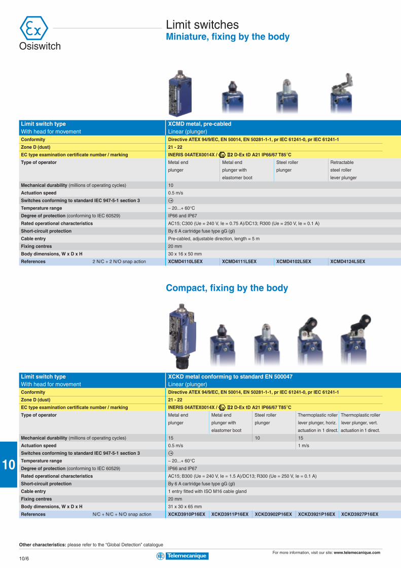
For more information, visit our site: www.telemecanique.com
10/6
10
Limit switchesMiniature, fixing by the body
Limit switch type XCMD metal, pre-cabledWith head for movement Linear (plunger)Conformity Directive ATEX 94/9/EC, EN 50014, EN 50281-1-1, pr IEC 61241-0, pr IEC 61241-1
Zone D (dust) 21 - 22
EC type examination certificate number / marking INERIS 04ATEX0014X / D-Ex tD A21 IP66/67 T85°CType of operator Metal end Metal end Steel roller Retractable
plunger plunger with plunger steel roller
elastomer boot lever plunger
Mechanical durability (millions of operating cycles) 10
Actuation speed 0.5 m/s
Switches conforming to standard IEC 947-5-1 section 3
Temperature range – 20...+ 60°CDegree of protection (conforming to IEC 60529) IP66 and IP67
Rated operational characteristics AC15; C300 (Ue = 240 V, Ie = 0.75 A)/DC13; R300 (Ue = 250 V, Ie = 0.1 A)
Short-circuit protection By 6 A cartridge fuse type gG (gl)
Cable entry Pre-cabled, adjustable direction, length = 5 m
Fixing centres 20 mm
Body dimensions, W x D x H 30 x 16 x 50 mm
References 2 N/C + 2 N/O snap action XCMD4110L5EX XCMD4111L5EX XCMD4102L5EX XCMD4124L5EX
Compact, fixing by the body
Limit switch type XCKD metal conforming to standard EN 500047With head for movement Linear (plunger)Conformity Directive ATEX 94/9/EC, EN 50014, EN 50281-1-1, pr IEC 61241-0, pr IEC 61241-1
Zone D (dust) 21 - 22
EC type examination certificate number / marking INERIS 04ATEX0014X / D-Ex tD A21 IP66/67 T85°CType of operator Metal end Metal end Steel roller Thermoplastic roller Thermoplastic roller
plunger plunger with plunger lever plunger, horiz. lever plunger, vert.
elastomer boot actuation in 1 direct. actuation in 1 direct.
Mechanical durability (millions of operating cycles) 15 10 15
Actuation speed 0.5 m/s 1 m/s
Switches conforming to standard IEC 947-5-1 section 3
Temperature range – 20...+ 60°CDegree of protection (conforming to IEC 60529) IP66 and IP67
Rated operational characteristics AC15; B300 (Ue = 240 V, Ie = 1.5 A)/DC13; R300 (Ue = 250 V, Ie = 0.1 A)
Short-circuit protection By 6 A cartridge fuse type gG (gl)
Cable entry 1 entry fitted with ISO M16 cable gland
Fixing centres 20 mm
Body dimensions, W x D x H 31 x 30 x 65 mm
References N/C + N/C + N/O snap action XCKD3910P16EX XCKD3911P16EX XCKD3902P16EX XCKD3921P16EX XCKD3927P16EX
Other characteristics: please refer to the “Global Detection” catalogue
Osiswitch
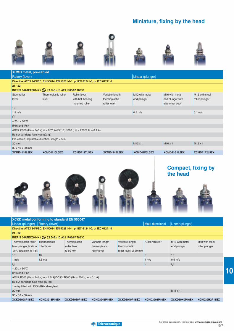
For more information, visit our site: www.telemecanique.com
10/7
10
XCMD metal, pre-cabledRotary (lever) Linear (plunger)Directive ATEX 94/9/EC, EN 50014, EN 50281-1-1, pr IEC 61241-0, pr IEC 61241-1
21 - 22
INERIS 04ATEX0014X / D-Ex tD A21 IP66/67 T85°CSteel roller Thermoplastic roller Roller lever Variable length M12 with metal M16 with metal M12 with steel
lever lever with ball bearing thermoplastic end plunger end plunger with roller plunger
mounted roller roller lever elastomer boot
10
1.5 m/s 0.5 m/s 0.1 m/s
– 20...+ 60°CIP66 and IP67
AC15; C300 (Ue = 240 V, Ie = 0.75 A)/DC13; R300 (Ue = 250 V, Ie = 0.1 A)
By 6 A cartridge fuse type gG (gl)
Pre-cabled, adjustable direction, length = 5 m
20 mm M12 x 1 M16 x 1 M12 x 1
30 x 16 x 50 mm
XCMD4116L5EX XCMD4115L5EX XCMD4117L5EX XCMD4145L5EX XCMD41F0L5EX XCMD41G1L5EX XCMD41F2L5EX
Compact, fixing bythe head
XCKD metal conforming to standard EN 500047Linear (plunger) Rotary (lever) Multi-directional Linear (plunger)Directive ATEX 94/9/EC, EN 50014, EN 50281-1-1, pr IEC 61241-0, pr IEC 61241-1
21 - 22
INERIS 04ATEX0014X / D-Ex tD A21 IP66/67 T85°CThermoplastic roller Thermoplastic Thermoplastic Variable length Variable length “Cat’s whisker” M18 with metal M18 with steel
lever plunger, horiz. or roller lever roller lever, thermoplastic thermoplastic end plunger roller plunger
vert. actuation in 1 dir. Ø 50 mm roller lever roller lever, Ø 50 mm
15 10 5 10
1 m/s 1.5 m/s 1 m/s 0.5 m/s
–
– 20...+ 60°CIP66 and IP67
AC15; B300 (Ue = 240 V, Ie = 1.5 A)/DC13; R300 (Ue = 250 V, Ie = 0.1 A)
By 6 A cartridge fuse type gG (gl)
1 entry fitted with ISO M16 cable gland
20 mm M18 x 1
30 x 16 x 50 mm
XCKD3928P16EX XCKD3918P16EX XCKD3939P16EX XCKD3945P16EX XCKD3949P16EX XCKD3906P16EX XCKD39H0P16EX XCKD39H2P16EX
Miniature, fixing by the head

For more information, visit our site: www.telemecanique.com
10/8
10
Limit switchesClassic, fixing by the body
Limit switch type XCKM metal, 3 cable entriesWith head for movement Linear (plunger) Rotary (lever) Multi-directionalConformity Directive ATEX 94/9/EC, EN 50014, EN 50281-1-1, pr IEC 61241-0, pr IEC 61241-1
Zone D (dust) 21 - 22
EC type examination certificate number / marking INERIS 04ATEX0014X / D-Ex tD A21 IP66/67 T85°CType of operator Metal end Steel roller Thermoplastic roller Thermoplastic “Cat’s whisker”
plunger plunger lever plunger, horiz. roller lever
actuation in 1 direct.
Mechanical durability (millions of operating cycles) 20 10
Actuation speed 0.5 m/s 1.5 m/s 0.5 m/s
Switches conforming to standard IEC 947-5-1 section 3 –
Temperature range – 20...+ 60°CDegree of protection (conforming to IEC 60529) IP66
Rated operational characteristics AC15; B300 (Ue = 240 V, Ie = 1.5 A)/DC13; R300 (Ue = 250 V, Ie = 0.1 A)
Short-circuit protection By 6 A cartridge fuse type gG (gl)
Cable entry 3 tapped entries for ISO M20 cable gland (1)
Fixing centres 41 mm
Body dimensions, W x D x H 63 x 30 x 64 mm
References N/C + N/C + N/O snap action XCKM3910H29EX XCKM3902H29EX XCKM3921H29EX XCKM3915H29EX XCKM3906H29EX
(1) 2 entries fitted with blanking plugs, 1 entry fitted with ISO M20 cable gland
Application - hoisting, handling, conveying
Limit switch type XCKMR metal, 3 cable entriesWith head for movement Rotary (lever)Conformity Directive ATEX 94/9/EC, EN 50014, EN 50281-1-1, pr IEC 61241-0, pr IEC 61241-1
Zone D (dust) 21 - 22
EC type examination certificate number / marking INERIS 04ATEX0014X / D-Ex tD A21 IP66/67 T85°CType of operator Metal rod levers, ”crossed” Metal rod levers, ”crossed”
reversed head
Mechanical durability (millions of operating cycles) 2
Actuation speed 1.5 m/s
Switches conforming to standard IEC 947-5-1 section 3
Temperature range – 20...+ 60°CDegree of protection (conforming to IEC 60529) IP66
Rated operational characteristics AC15; A300 (Ue = 240 V, Ie = 3 A)/DC13; Q300 (Ue = 125 V, Ie = 0.55 A)
Short-circuit protection By 10 A cartridge fuse type gG (gl)
Cable entry 3 tapped entries for ISO M20 cable gland (1)
Fixing centres 61.5 mm
Body dimensions, W x D x H 118 x 59 x 77 mm
2 x N/C + N/C staggered, slow break contacts XCKMR54D1H29EX XCKMR54D2H29EX
2 x N/C + N/O snap action contacts, both actuated in each direction –
2 x N/C + N/O snap action contacts, 1 actuated in each direction –
2 x single-pole C/O snap action contacts –
(1) 2 entries fitted with blanking plugs, 1 entry fitted with ISO M20 cable gland
Other characteristics: please refer to the “Global Detection” catalogue
Osiswitch
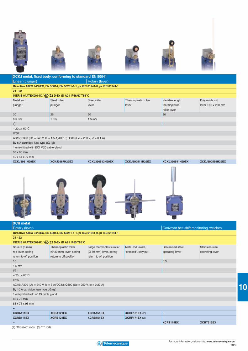
For more information, visit our site: www.telemecanique.com
10/9
10
XCKJ metal, fixed body, conforming to standard EN 50041Linear (plunger) Rotary (lever)Directive ATEX 94/9/EC, EN 50014, EN 50281-1-1, pr IEC 61241-0, pr IEC 61241-1
21 - 22
INERIS 04ATEX0014X / D-Ex tD A21 IP66/67 T85°CMetal end Steel roller Steel roller Thermoplastic roller Variable length Polyamide rod
plunger plunger lever lever thermoplastic lever, Ø 6 x 200 mm
roller lever
30 25 30 20
0.5 m/s 1 m/s 1.5 m/s
–
– 20...+ 60°CIP66
AC15; B300 (Ue = 240 V, Ie = 1.5 A)/DC13; R300 (Ue = 250 V, Ie = 0.1 A)
By 6 A cartridge fuse type gG (gl)
1 entry fitted with ISO M20 cable gland
30 x 60 mm
40 x 44 x 77 mm
XCKJ3961H29EX XCKJ3967H29EX XCKJ390513H29EX XCKJ390511H29EX XCKJ390541H29EX XCKJ390559H29EX
XCR metalRotary (lever) Conveyor belt shift monitoring switchesDirective ATEX 94/9/EC, EN 50014, EN 50281-1-1, pr IEC 61241-0, pr IEC 61241-1
21 - 22
INERIS 04ATEX0024X / D-Ex tD A21 IP65 T85°CSquare (6 mm) Thermoplastic roller Large thermoplastic roller Metal rod levers, Galvanised steel Stainless steel
rod lever, spring (Ø 30 mm) lever, spring (Ø 50 mm) lever, spring ”crossed”, stay put operating lever operating lever
return to off position return to off position return to off position
10 0.3
1.5 m/s
–
– 20...+ 60°CIP65
AC15; A300 (Ue = 240 V, Ie = 3 A)/DC13; Q300 (Ue = 250 V, Ie = 0.27 A)
By 10 A cartridge fuse type gG (gl)
1 entry fitted with n° 13 cable gland
85 x 75 mm
85 x 75 x 95 mm
–
XCRA111EX XCRA121EX XCRA151EX XCRE181EX (2) –
XCRB111EX XCRB121EX XCRB151EX XCRF171EX (3) –
– XCRT115EX XCRT215EX
(2) “Crossed” rods (3) “T” rods

For more information, visit our site: www.telemecanique.com
10/10
10
Electromechanical pressure & vacuum switchesAdjustable differential, regulation between 2 thresholds
Type Vacuum switches and vacu-pressure switches with setting scaleSize - 1 bar - 0.2 bar 5 barConformity Directive ATEX 94/9/EC, EN 50014, EN 50281-1-1, pr IEC 61241-0, pr IEC 61241-1
Zone D (dust) 21 - 22
EC type examination certificate number / marking INERIS 04ATEX0058 / D-Ex tD A21 IP66 T85°CFluid connection 1/4" BSP female
Electrical connection Screw terminals, 1 entry fitted with ISO M20 cable gland
Temperature range – 20...+ 60°CDegree of protection IP66
Rated operational characteristics AC15; B300 (Ue = 240 V, Ie = 1.5 A; Ue = 120 V, Ie = 3 A)/DC13; R300 (Ue = 250 V, Ie = 0.1 A)
Short-circuit protection By 10 A cartridge fuse type gG (gl)
Setting range of upper limit (PH) –0.14…–1 bar –0.02…–0.2 bar –0.5…5 bar
Body dimensions, W x D x H 55 x 77.5 x 158 mm 150 x 155.5 x 145 mm 113 x 35 x 75 mm
Fluids controlled Oil, water, air, up to +70°C Oil, air, up to +160°C Oil, water, air, up to +70°CPossible differential Min. at low setting 0.13 bar 0.018 bar 0.5 bar
(subtract from PH Min. at high setting 0.13 bar 0.018 bar 0.5 bar
to give PB) (1) Max. at high setting 0.8 bar 0.18 bar 6 bar
Single-pole snap action contact XMLBM02V2S12EX XMLBM03R2S12EX XMLBM05A2S12EX
(1) For XMLBM02V2S12EX and XMLBM03R2S12EX vacuum switches add to PB to give PH
Type Pressure switches with setting scaleSize 10 bar 20 bar 35 barConformity Directive ATEX 94/9/EC, EN 50014, EN 50281-1-1, pr IEC 61241-0, pr IEC 61241-1
Zone D (dust) 21 - 22
EC type examination certificate number / marking INERIS 04ATEX0058 / D-Ex tD A21 IP66 T85°CFluid connection 1/4" BSP female
Electrical connection Screw terminals, 1 entry fitted with ISO M20 cable gland
Temperature range – 20...+ 60°CDegree of protection IP66
Rated operational characteristics AC15; B300 (Ue = 240 V, Ie = 1.5 A; Ue = 120 V, Ie = 3 A)/DC13; R300 (Ue = 250 V, Ie = 0.1 A)
Short-circuit protection By 10 A cartridge fuse type gG (gl)
Setting range of upper limit (PH) 0.7…10 bar 1.3…20 bar 3.5…35 bar
Body dimensions, W x D x H 35 x 75 x 113 mm
Fluids controlled Oil, water, air, up to +70°CPossible differential Min. at low setting 0.57 bar 1 bar 1.7 bar
(subtract from PH Min. at high setting 0.85 bar 1.6 bar 2.55 bar
to give PB) Max. at high setting 7.5 bar 11 bar 20 bar
Single-pole snap action contact XMLB010A2S12EX XMLB020A2S12EX XMLB035A2S12EX
Other characteristics: please refer to the “Global Detection” catalogue
Nautilus

For more information, visit our site: www.telemecanique.com
10/11
10
Pressure switches with setting scale0.05 bar 0.35 bar 1 bar 2.5 bar 4 barDirective ATEX 94/9/EC, EN 50014, EN 50281-1-1, pr IEC 61241-0, pr IEC 61241-1
21 - 22
INERIS 04ATEX0058 / D-Ex tD A21 IP66 T85°C1/4" BSP female
Screw terminals, 1 entry fitted with ISO M20 cable gland
– 20...+ 60°CIP66
AC15; B300 (Ue = 240 V, Ie = 1.5 A; Ue = 120 V, Ie = 3 A)/DC13; R300 (Ue = 250 V, Ie = 0.1 A)
By 10 A cartridge fuse type gG (gl)
0.026…0.05 bar 0.045…0.35 bar 0.05…1 bar 0.3…2.5 bar 0.25…4 bar
200 x 204 x 145 mm 110 x 110 x 162 mm 55 x 77.5 x 158 mm 55 x 77.5 x 158 mm
Oil, air, up to +160°C Oil, water, air, up to +70°C0.0014 bar 0.042 bar 0.04 bar 0.16 bar 0.2 bar
0.004 bar 0.05 bar 0.06 bar 0.21 bar 0.25 bar
0.04 bar 0.3 bar 0.75 bar 1.75 bar 2.4 bar
XMLBL05R2S12EX XMLBL35R2S12EX XMLB001R2S12EX XMLB002A2S12EX XMLB004A2S12EX
Pressure switches with setting scale70 bar 160 bar 300 bar 500 barDirective ATEX 94/9/EC, EN 50014, EN 50281-1-1, pr IEC 61241-0, pr IEC 61241-1
21 - 22
INERIS 04ATEX0058 / D-Ex tD A21 IP66 T85°C1/4" BSP female
Screw terminals, 1 entry fitted with ISO M20 cable gland
– 20...+ 60°CIP66
AC15; B300 (Ue = 240 V, Ie = 1.5 A; Ue = 120 V, Ie = 3 A)/DC13; R300 (Ue = 250 V, Ie = 0.1 A)
By 10 A cartridge fuse type gG (gl)
7…70 bar 10…160 bar 22…300 bar 30…500 bar
35 x 75 x 113 mm
Oil, up to +160°C4.7 bar 9.3 bar 19.4 bar 23 bar
8.8 bar 20.8 bar 37 bar 52.6 bar
50 bar 100 bar 200 bar 300 bar
XMLB070D2S12EX XMLB160D2S12EX XMLB300D2S12EX XMLB500D2S12EX
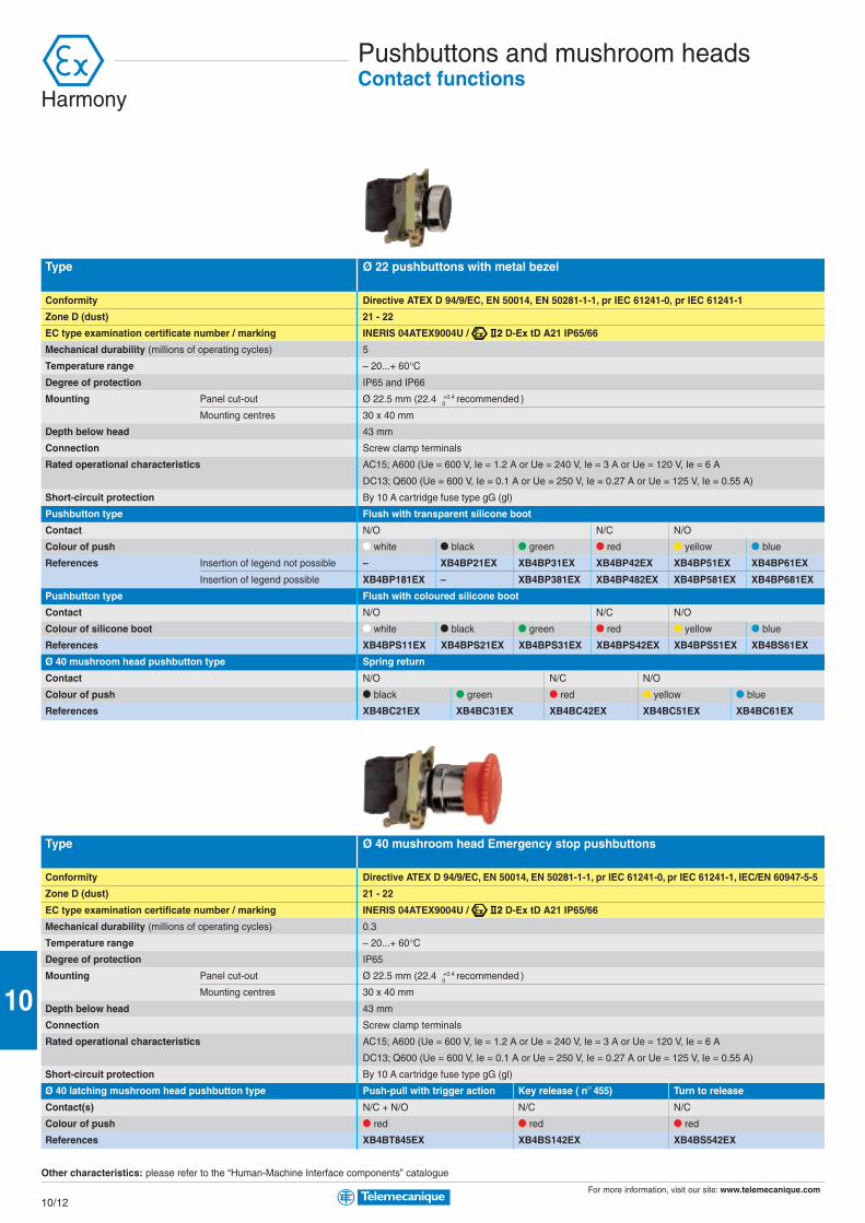
For more information, visit our site: www.telemecanique.com
10/12
10
Pushbuttons and mushroom headsContact functions
Type Ø 22 pushbuttons with metal bezel
Conformity Directive ATEX D 94/9/EC, EN 50014, EN 50281-1-1, pr IEC 61241-0, pr IEC 61241-1
Zone D (dust) 21 - 22
EC type examination certificate number / marking INERIS 04ATEX9004U / D-Ex tD A21 IP65/66
Mechanical durability (millions of operating cycles) 5
Temperature range – 20...+ 60°CDegree of protection IP65 and IP66
Mounting Panel cut-out Ø 22.5 mm (22.4 0 +0.4 recommended )
Mounting centres 30 x 40 mm
Depth below head 43 mm
Connection Screw clamp terminals
Rated operational characteristics AC15; A600 (Ue = 600 V, Ie = 1.2 A or Ue = 240 V, Ie = 3 A or Ue = 120 V, Ie = 6 A
DC13; Q600 (Ue = 600 V, Ie = 0.1 A or Ue = 250 V, Ie = 0.27 A or Ue = 125 V, Ie = 0.55 A)
Short-circuit protection By 10 A cartridge fuse type gG (gl)
Pushbutton type Flush with transparent silicone boot
Contact N/O N/C N/O
Colour of push p white p black p green p red p yellow p blue
References Insertion of legend not possible – XB4BP21EX XB4BP31EX XB4BP42EX XB4BP51EX XB4BP61EX
Insertion of legend possible XB4BP181EX – XB4BP381EX XB4BP482EX XB4BP581EX XB4BP681EX
Pushbutton type Flush with coloured silicone boot
Contact N/O N/C N/O
Colour of silicone boot p white p black p green p red p yellow p blue
References XB4BPS11EX XB4BPS21EX XB4BPS31EX XB4BPS42EX XB4BPS51EX XB4BS61EX
Ø 40 mushroom head pushbutton type Spring return
Contact N/O N/C N/O
Colour of push p black p green p red p yellow p blue
References XB4BC21EX XB4BC31EX XB4BC42EX XB4BC51EX XB4BC61EX
Type Ø 40 mushroom head Emergency stop pushbuttons
Conformity Directive ATEX D 94/9/EC, EN 50014, EN 50281-1-1, pr IEC 61241-0, pr IEC 61241-1, IEC/EN 60947-5-5
Zone D (dust) 21 - 22
EC type examination certificate number / marking INERIS 04ATEX9004U / D-Ex tD A21 IP65/66
Mechanical durability (millions of operating cycles) 0.3
Temperature range – 20...+ 60°CDegree of protection IP65
Mounting Panel cut-out Ø 22.5 mm (22.4 0 +0.4 recommended )
Mounting centres 30 x 40 mm
Depth below head 43 mm
Connection Screw clamp terminals
Rated operational characteristics AC15; A600 (Ue = 600 V, Ie = 1.2 A or Ue = 240 V, Ie = 3 A or Ue = 120 V, Ie = 6 A
DC13; Q600 (Ue = 600 V, Ie = 0.1 A or Ue = 250 V, Ie = 0.27 A or Ue = 125 V, Ie = 0.55 A)
Short-circuit protection By 10 A cartridge fuse type gG (gl)
Ø 40 latching mushroom head pushbutton type Push-pull with trigger action Key release ( n° 455) Turn to release
Contact(s) N/C + N/O N/C N/C
Colour of push p red p red p red
References XB4BT845EX XB4BS142EX XB4BS542EX
Other characteristics: please refer to the “Human-Machine Interface components” catalogue
Harmony
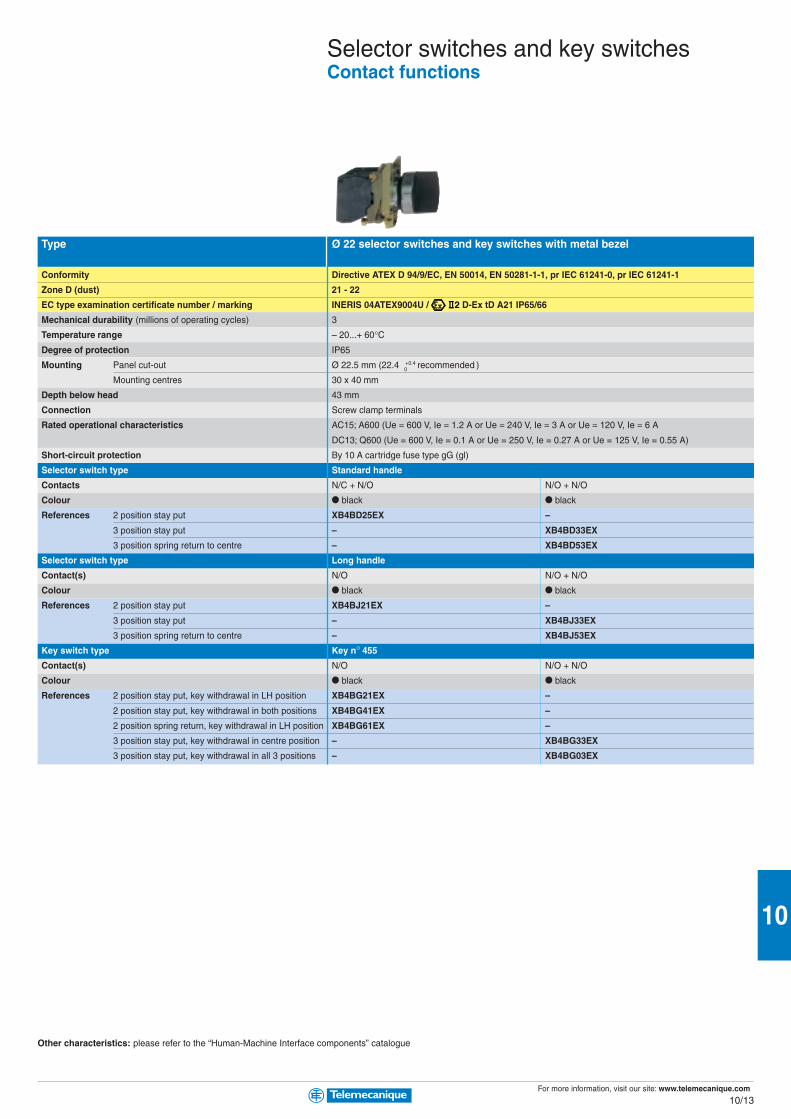
For more information, visit our site: www.telemecanique.com
10/13
10
Type Ø 22 selector switches and key switches with metal bezel
Conformity Directive ATEX D 94/9/EC, EN 50014, EN 50281-1-1, pr IEC 61241-0, pr IEC 61241-1
Zone D (dust) 21 - 22
EC type examination certificate number / marking INERIS 04ATEX9004U / D-Ex tD A21 IP65/66
Mechanical durability (millions of operating cycles) 3
Temperature range – 20...+ 60°CDegree of protection IP65
Mounting Panel cut-out Ø 22.5 mm (22.4 0 +0.4 recommended )
Mounting centres 30 x 40 mm
Depth below head 43 mm
Connection Screw clamp terminals
Rated operational characteristics AC15; A600 (Ue = 600 V, Ie = 1.2 A or Ue = 240 V, Ie = 3 A or Ue = 120 V, Ie = 6 A
DC13; Q600 (Ue = 600 V, Ie = 0.1 A or Ue = 250 V, Ie = 0.27 A or Ue = 125 V, Ie = 0.55 A)
Short-circuit protection By 10 A cartridge fuse type gG (gl)
Selector switch type Standard handle
Contacts N/C + N/O N/O + N/O
Colour p black p black
References 2 position stay put XB4BD25EX –
3 position stay put – XB4BD33EX
3 position spring return to centre – XB4BD53EX
Selector switch type Long handle
Contact(s) N/O N/O + N/O
Colour p black p black
References 2 position stay put XB4BJ21EX –
3 position stay put – XB4BJ33EX
3 position spring return to centre – XB4BJ53EX
Key switch type Key n° 455
Contact(s) N/O N/O + N/O
Colour p black p black
References 2 position stay put, key withdrawal in LH position XB4BG21EX –
2 position stay put, key withdrawal in both positions XB4BG41EX –
2 position spring return, key withdrawal in LH position XB4BG61EX –
3 position stay put, key withdrawal in centre position – XB4BG33EX
3 position stay put, key withdrawal in all 3 positions – XB4BG03EX
Other characteristics: please refer to the “Human-Machine Interface components” catalogue
Selector switches and key switchesContact functions

For more information, visit our site: www.telemecanique.com
10/14
10
Illuminated pushbuttons and pilot lightsContact and light functions (integral LED)
Type Ø 22 illuminated pushbuttons with metal bezel
Conformity Directive ATEX 94/9/EC, EN 50014, EN 50281-1-1, pr IEC 61241-0, pr IEC 61241-1
Zone D (dust) 21 - 22
EC type examination certificate number / marking INERIS 04ATEX9004U / D-Ex tD A21 IP65/66
Mechanical durability (millions of operating cycles) 5
Service life 100,000 hours at ambient temperature
Temperature range – 20...+ 60°CDegree of protection IP65
Mounting Panel cut-out Ø 22.5 mm (22.4 0 +0.4 recommended )
Mounting centres 30 x 40 mm
Depth below head 43 mm
Connection Screw clamp terminals
Rated operational characteristics AC15; A600 (Ue = 600 V, Ie = 1.2 A or Ue = 240 V, Ie = 3 A or Ue = 120 V, Ie = 6 A
DC13; Q600 (Ue = 600 V, Ie = 0.1 A or Ue = 250 V, Ie = 0.27 A or Ue = 125 V, Ie = 0.55 A)
Short-circuit protection By 10 A cartridge fuse type gG (gl)
Light source Integral LED
Illuminated pushbutton type, with integral LED Flush with transparent silicone boot
Contact N/O N/C N/O
Colour of push p white p green p red p yellow p blue
References LED voltage 24 VAC/DC XB4BP183B5EX XB4BP383B5EX XB4BP483B5EX XB4BP583B5EX XB4BP683B5EX
48…120 VAC XB4BP183G5EX XB4BP383G5EX XB4BP483G5EX XB4BP583G5EX XB4BP683G5EX
240 VAC XB4BP183M5EX XB4BP383M5EX XB4BP483M5EX XB4BP583M5EX XB4BP683M5EX
24…120 VAC/DC XB4BP183BG5EX XB4BP383BG5EX XB4BP483BG5EX XB4BP583BG5EX XB4BP683BG5EX
Type Ø 22 pilot lights with metal bezel
Conformity Directive ATEX 94/9/EC, EN 50014, EN 50281-1-1, pr IEC 61241-0, pr IEC 61241-1
Zone D (dust) 21 - 22
EC type examination certificate number / marking INERIS 04ATEX9004U / D-Ex tD A21 IP65/66
Service life 100,000 hours at ambient temperature
Temperature range – 20...+ 60°CDegree of protection IP65
Mounting Panel cut-out Ø 22.5 mm (22.4 0 +0.4 recommended )
Mounting centres 30 x 40 mm
Depth below head 43 mm
Connection Screw clamp terminals
Rated operational characteristics AC15; A600 (Ue = 600 V, Ie = 1.2 A or Ue = 240 V, Ie = 3 A or Ue = 120 V, Ie = 6 A
DC13; Q600 (Ue = 600 V, Ie = 0.1 A or Ue = 250 V, Ie = 0.27 A or Ue = 125 V, Ie = 0.55 A)
Short-circuit protection By 10 A cartridge fuse type gG (gl)
Light source Integral LED
Pilot light type Pilot lights with integral LED, plain lens
Colour of LED p white p green p red p yellow p blue
References LED voltage 24 VAC/DC XB4BVB1EX XB4BVB3EX XB4BVB4EX XB4BVB5EX XB4BVB6EX
48…120 VAC XB4BVG1EX XB4BVG3EX XB4BVG4EX XB4BVG5EX XB4BVG6EX
240 VAC XB4BVM1EX XB4BVM3EX XB4BVM4EX XB4BVM5EX XB4BVM6EX
24…120 VAC/DC XB4BVBG1EX XB4BVBG3EX XB4BVBG4EX XB4BVBG5EX XB4BVBG6EX
Other characteristics: please refer to the “Human-Machine Interface components” catalogue
Harmony

For more information, visit our site: www.telemecanique.com
10/15
10
Control stationsComplete stations, metal or plastic
Type Complete control stationsType of operators Ø 22 flush pushbuttons
Conformity Directive ATEX 94/9/EC, EN 50014, EN 50281-1-1, pr IEC 61241-0, pr IEC 61241-1
Zone D (dust) 21 - 22
EC type examination certificate number / marking INERIS 04ATEX0023 / D-Ex tD A21 IP65 T85°CTemperature range – 20...+ 60°CDegree of protection IP65
Connection 1 entry fitted with ISO M20 cable gland
Rated operational characteristics of contact blocks AC15; A600 (Ue = 600 V, Ie = 1.2 A or Ue = 240 V, Ie = 3 A or Ue = 120 V, Ie = 6 A
DC13; Q600 (Ue = 600 V, Ie = 0.1 A or Ue = 250 V, Ie = 0.27 A or Ue = 125 V, Ie = 0.55 A)
Short-circuit protection By 10 A cartridge fuse type gG (gl)
Function 1 function, Start or Stop 2 functions, Start - Stop 3 functions
Composition 1 spring return pushbutton 2 spring ret. pushbuttons 3 spring ret. pushbuttons
Contact(s) N/O N/C N/O + N/C N/O + N/C + N/O
Colour of pushbutton(s) p green p red p green + p red p green + p red + p black
Metal control stations Dimensions, W x D x H 80 x 77 x 80 mm 80 x 77 x 130 mm 80 x 77 x 175 mm
Fixings: 4 x Ø 5.6 mm, centres 50 x 65 mm 50 x 115 mm 50 x 160 mm
References XAWF100EX XAWF110EX XAWF210EX XAWF310EX
Plastic control stations Dimensions, W x D x H 85 x 70 x 146 mm 85 x 70 x 226 mm
Fixings: 4 x Ø 5.6 mm, centres 70 x 105 mm 70 x 108 mm
References XAWG100EX XAWG110EX XAWG210EX XAWG310EX
Type Complete control stationsType of operator Ø 22 selector switch or key switch with metal bezel Ø 40 mushroom head Emergency stop
Conformity Directive ATEX 94/9/EC, EN 50014, EN 50281-1-1, pr IEC 61241-0, pr IEC 61241-1
Zone D (dust) 21 - 22
EC type examination certificate number / marking INERIS 04ATEX0023 / D-Ex tD A21 IP65 T85°CTemperature range – 20...+ 60°CDegree of protection IP65
Connection 1 entry fitted with ISO M20 cable gland
Rated operational characteristics of contact blocks AC15; A600 (Ue = 600 V, Ie = 1.2 A or Ue = 240 V, Ie = 3 A or Ue = 120 V, Ie = 6 A
DC13; Q600 (Ue = 600 V, Ie = 0.1 A or Ue = 250 V, Ie = 0.27 A or Ue = 125 V, Ie = 0.55 A)
Short-circuit protection By 10 A cartridge fuse type gG (gl)
Function 1 function, Start/Stop Emergency stop
Composition 1 selector switch (1) 1 key switch (1) 1 Ø 40 mushroom head 1 Ø 40 mushroom head 1 push/pull Ø 40
standard black handle key n° 455 turn to release key release with trigger action
Contact N/O + N/C N/O + N/C N/C + N/C N/C + N/C N/C + N/C
Colour of operator p black p black p red p red p red
Metal control stations Dimensions, W x D x H 80 x 77 x 80 mm
Fixings: 4 x Ø 5.6 mm, centres 50 x 65 mm
References XAWF130EX XAWF140EX XAWF174EX XAWF184EX XAWF198EX
Plastic control stations Dimensions, W x D x H 80 x 70 x 146 mm
Fixings: 4 x Ø 5.6 mm, centres 70 x 105 mm
References XAWG130EX XAWG140EX XAWG174EX XAWG184EX XAWG198EX
(1) 2 position stay put
Other characteristics: please refer to the “Human-Machine Interface components” catalogue
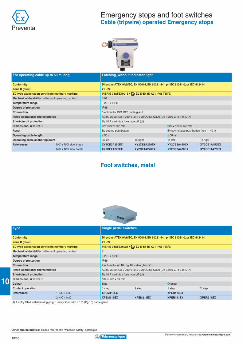
For more information, visit our site: www.telemecanique.com
10/16
10
Emergency stops and foot switchesCable (tripwire) operated Emergency stops
For operating cable up to 50 m long Latching, without indicator light
Conformity Directive ATEX 94/9/EC, EN 50014, EN 50281-1-1, pr IEC 61241-0, pr IEC 61241-1
Zone D (dust) 21 - 22
EC type examination certificate number / marking INERIS 04ATEX0015 / D-Ex tD A21 IP65 T85°CMechanical durability (millions of operating cycles) 0.01
Temperature range – 20...+ 60°CDegree of protection IP65
Connection 3 entries for ISO M20 cable gland
Rated operational characteristics AC15; A300 (Ue = 240 V, Ie = 3 A)/DC13; Q300 (Ue = 250 V, Ie = 0.27 A)
Short-circuit protection By 10 A cartridge fuse type gG (gl)
Dimensions, W x D x H 229 x 82 x 142 mm 229 x 105 x 142 mm
Reset By booted pushbutton By key release pushbutton (key n° 421)
Operating cable length ≤ 50 m ≤ 50 m
Operating cable anchoring point To left To right To left To right
References N/C + N/O slow break XY2CE2A250EX XY2CE1A250EX XY2CE2A450EX XY2CE1A450EX
N/C + N/C slow break XY2CE2A270EX XY2CE1A270EX XY2CE2A470EX XY2CE1A470EX
Foot switches, metal
Type Single pedal switches
Conformity Directive ATEX 94/9/EC, EN 50014, EN 50281-1-1, pr IEC 61241-0, pr IEC 61241-1
Zone D (dust) 21 - 22
EC type examination certificate number / marking INERIS 04ATEX0025 / D-Ex tD A21 IP65 T85°CMechanical durability (millions of operating cycles) 5
Temperature range – 20...+ 60°CDegree of protection IP66
Connection 2 entries for n° 16 (Pg 16) cable gland (1)
Rated operational characteristics AC15; A300 (Ue = 240 V, Ie = 3 A)/DC13; Q300 (Ue = 250 V, Ie = 0.27 A)
Short-circuit protection By 10 A cartridge fuse type gG (gl)
Dimensions, W x D x H 104 x 172 x 59 mm
Colour Blue Orange
Contact operation 1 step 2 step 1 step 2 step
References 1 N/C + N/O XPEM110EX – XPER110EX –
2 N/C + N/O XPEM111EX XPEM211EX XPER111EX XPER211EX
(1) 1 entry fitted with blanking plug, 1 entry fitted with n° 16 (Pg 16) cable gland
Other characteristics: please refer to the “Machine safety” catalogue
Preventa
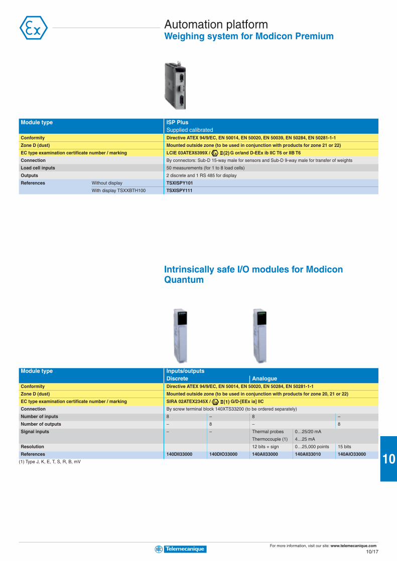
For more information, visit our site: www.telemecanique.com
10/17
10
Automation platformWeighing system for Modicon Premium
Module type ISP PlusSupplied calibrated
Conformity Directive ATEX 94/9/EC, EN 50014, EN 50020, EN 50039, EN 50284, EN 50281-1-1
Zone D (dust) Mounted outside zone (to be used in conjunction with products for zone 21 or 22)
EC type examination certificate number / marking LCIE 03ATEX6399X / G or/and D-EEx ib IIC T6 or IIB T6
Connection By connectors: Sub-D 15-way male for sensors and Sub-D 9-way male for transfer of weights
Load cell inputs 50 measurements (for 1 to 8 load cells)
Outputs 2 discrete and 1 RS 485 for display
References Without display TSXISPY101
With display TSXXBTH100 TSXISPY111
Intrinsically safe I/O modules for ModiconQuantum
Module type Inputs/outputsDiscrete Analogue
Conformity Directive ATEX 94/9/EC, EN 50014, EN 50020, EN 50284, EN 50281-1-1
Zone D (dust) Mounted outside zone (to be used in conjunction with products for zone 20, 21 or 22)
EC type examination certificate number / marking SIRA 02ATEX2345X / G/D-[EEx ia] IIC
Connection By screw terminal block 140XTS33200 (to be ordered separately)
Number of inputs 8 – 8 –
Number of outputs – 8 – 8
Signal inputs – – Thermal probes 0…25/20 mA
Thermocouple (1) 4…25 mA
Resolution 12 bits + sign 0…25,000 points 15 bits
References 140DII33000 140DIO33000 140AII33000 140AII33010 140AIO33000
(1) Type J, K, E, T, S, R, B, mV
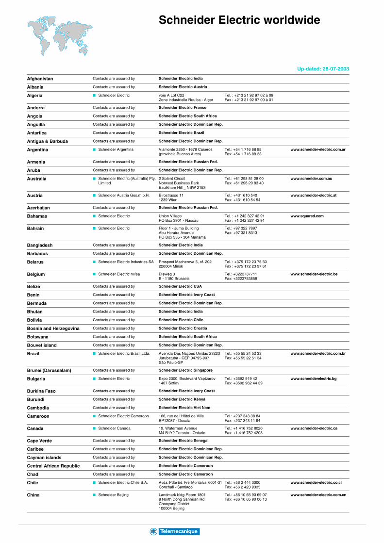
Schneider Electric worldwide
Afghanistan Contacts are assured by Schneider Electric India
Albania Contacts are assured by Schneider Electric Austria
Algeria b Schneider Electric voie A Lot C22Zone industrielle Rouiba - Alger
Tel. : +213 21 92 97 02 à 09Fax : +213 21 92 97 00 à 01
Andorra Contacts are assured by Schneider Electric France
Angola Contacts are assured by Schneider Electric South Africa
Anguilla Contacts are assured by Schneider Electric Dominican Rep.
Antartica Contacts are assured by Schneider Electric Brazil
Antigua & Barbuda Contacts are assured by Schneider Electric Dominican Rep.
Argentina b Schneider Argentina Viamonte 2850 - 1678 Caseros(provincia Buenos Aires)
Tel.: +54 1 716 88 88Fax: +54 1 716 88 33
www.schneider-electric.com.ar
Armenia Contacts are assured by Schneider Electric Russian Fed.
Aruba Contacts are assured by Schneider Electric Dominican Rep.
Australia b Schneider Electric (Australia) Pty. Limited
2 Solent CircuitNorwest Business ParkBaulkham Hill _ NSW 2153
Tel.: +61 298 51 28 00Fax: +61 296 29 83 40
www.schneider.com.au
Austria b Schneider Austria Ges.m.b.H. Birostrasse 111239 Wien
Tel.: +431 610 540Fax: +431 610 54 54
www.schneider-electric.at
Azerbaijan Contacts are assured by Schneider Electric Russian Fed.
Bahamas b Schneider Electric Union VillagePO Box 3901 - Nassau
Tel. : +1 242 327 42 91Fax : +1 242 327 42 91
www.squared.com
Bahrain b Schneider Electric Floor 1 - Juma BuildingAbu Horaira AvenuePO Box 355 - 304 Manama
Tel.: +97 322 7897Fax: +97 321 8313
Bangladesh Contacts are assured by Schneider Electric India
Barbados Contacts are assured by Schneider Electric Dominican Rep.
Belarus b Schneider Electric Industries SA Prospect Macherova 5, of. 202220004 Minsk
Tel. : +375 172 23 75 50Fax : +375 172 23 97 61
Belgium b Schneider Electric nv/sa Dieweg 3B - 1180 Brussels
Tel.: +3223737711Fax: +3223753858
www.schneider-electric.be
Belize Contacts are assured by Schneider Electric USA
Benin Contacts are assured by Schneider Electric Ivory Coast
Bermuda Contacts are assured by Schneider Electric Dominican Rep.
Bhutan Contacts are assured by Schneider Electric India
Bolivia Contacts are assured by Schneider Electric Chile
Bosnia and Herzegovina Contacts are assured by Schneider Electric Croatia
Botswana Contacts are assured by Schneider Electric South Africa
Bouvet island Contacts are assured by Schneider Electric Dominican Rep.
Brazil b Schneider Electric Brazil Ltda. Avenida Das Nações Unidas 23223Jurubatuba - CEP 04795-907São Paulo-SP
Tel.: +55 55 24 52 33Fax: +55 55 22 51 34
www.schneider-electric.com.br
Brunei (Darussalam) Contacts are assured by Schneider Electric Singapore
Bulgaria b Schneider Electric Expo 2000, Boulevard Vaptzarov1407 Sofiav
Tel.: +3592 919 42Fax: +3592 962 44 39
www.schneiderelectric.bg
Burkina Faso Contacts are assured by Schneider Electric Ivory Coast
Burundi Contacts are assured by Schneider Electric Kenya
Cambodia Contacts are assured by Schneider Electric Viet Nam
Cameroon b Schneider Electric Cameroon 166, rue de l'Hôtel de VilleBP12087 - Douala
Tel.: +237 343 38 84Fax: +237 343 11 94
Canada b Schneider Canada 19, Waterman AvenueM4 B1Y2 Toronto - Ontario
Tel.: +1 416 752 8020Fax: +1 416 752 4203
www.schneider-electric.ca
Cape Verde Contacts are assured by Schneider Electric Senegal
Caribee Contacts are assured by Schneider Electric Dominican Rep.
Cayman islands Contacts are assured by Schneider Electric Dominican Rep.
Central African Republic Contacts are assured by Schneider Electric Cameroon
Chad Contacts are assured by Schneider Electric Cameroon
Chile b Schneider Electric Chile S.A. Avda. Pdte Ed. Frei Montalva, 6001-31 Conchali - Santiago
Tel.: +56 2 444 3000Fax: +56 2 423 9335
www.schneider-electric.co.cl
China b Schneider Beijing Landmark bldg-Room 18018 North Dong Sanhuan RdChaoyang District 100004 Beijing
Tel.: +86 10 65 90 69 07Fax: +86 10 65 90 00 13
www.schneider-electric.com.cn
Up-dated: 28-07-2003
Schneider Electric worldwide
Up-dated: 28-07-2003
Christmas island Contacts are assured by Schneider Electric Australia
Cocos (Keeling) islands Contacts are assured by Schneider Electric Australia
Colombia b Schneider Electric de Colombia S.A.
Calle 45A #102-48Bogota DC
Tel.: +57 1 426 97 00Fax: +57 1 426 97 40
Comoros Contacts are assured by Schneider Electric la Reunion
Congo Contacts are assured by Schneider Electric Cameroon
Cook islands Contacts are assured by Schneider Electric Australia
Costa Rica b Schneider Centroamérica Ltda. 1.5 kmts oeste de la Embajada Americana,Pavas, San José, Costa Rica C.A.Apartado: 4123-1000 San Jose
Tel.: +506 232-60-55Fax: +506 232-04-26
www.schneider-ca.com
Croatia b Schneider Electric SA Fallerovo Setaliste 22HR - 10000 Zagreb
Tel.: +385 1 367 100Fax: +385 1 367 111
Cuba b Schneider Electric Bureau de Liaison de La HavaneCalle 36- N˚306-Apto1Entre 3ra y 5ta Avenida MiramarPlaya Habana
Tel.: +53 724 15 59Fax: +53 724 12 17
Cyprus b Schneider Electric Cyprus 28 General Timayia AvenueKyriakos Building, Block #A301Larnaca 6046
Tel.: +00357 248 12646Fax: +00357 246 37382
Czech Republic b Schneider Electric CZ, s.r.o. Thámova 13Praha 8 - 186 00
Tel.: +420 2 810 88 111Fax: +420 2 24 81 08 49
www.schneider-electric.cz
Democratic Rep. of Congo Contacts are assured by Schneider Electric Cameroon
Denmark b Schneider Electric A/S Baltorpbakken 14DK-2750 Ballerup
Tel.: +45 44 73 78 88Fax: +45 44 68 5255
www.schneider-electric.dk
Djibouti Contacts are assured by Schneider Electric Egypt
Dominican Republic b Schneider Electric Calle Jacinto ManonEsq. Federico GeraldinoEdificio D' Roca Plaza Suite 402,Ens. Paraiso - Santo Domingo
Tel.: +1 809 334 66 63Fax: +1 809 334 66 68
Ecuador b Schneider Electric Ecuador SA Av.Republica del Salvador 1082 y Nac Edificio Mansion Blanca-Quito
Tel. : +593 2 224 42 42Fax : +593 2 224 42 94
Egypt b Schneider Electric Egypt sae 68, El Tayaran StreetNasr City, 11371 - Cairo
Tel.: +20 24 01 01 19Fax: +20 24 01 66 87
www.schneider.com.eg
El Salvador Contacts are assured by Schneider Electric USA
Equatorial Guinea Contacts are assured by Schneider Electric Cameroon
Eritrea Contacts are assured by Schneider Electric Egypt
Estonia b Lexel Electric Ehitajate tee 110EE 12618 Talinn
Tel. : +372 650 97 00Fax : +372 650 97 22
Ethiopia Contacts are assured by Schneider Electric Egypt
Falkland islands Contacts are assured by Schneider Electric Brazil
Faroe islands Contacts are assured by Schneider Electric Australia
Fiji Contacts are assured by Schneider Electric Australia
Finland b Schneider Electric Oy Sinimäentie 1402630 Espoo
Tel. : +358 9 527 000Fax : +358 9 5270 0376
www.schneider-electric.fi
France b Schneider Electric SA 5, rue Nadar92500 Rueil Malmaison
Tel.: +33 (0)1 41 29 82 00Fax: +33 (0)1 47 51 80 20
www.schneider-electric.fr
French Polynesia Contacts are assured by Schneider Electric Australia
French West Indies Contacts are assured by Schneider Electric Dominican Rep.
Gabon Contacts are assured by Schneider Electric Cameroon
Gambia Contacts are assured by Schneider Electric Senegal
Georgia Contacts are assured by Schneider Electric Russian Fed.
Germany b Schneider Electric GmbH Gothaer Straße 29D-40880 Ratingen
Tel.: +49210 240 40Fax: +492 10 240 49 256
www.schneiderelectric.de
Ghana b Schneider Electric Ghana PMB Kia3rd Floor Opeibea HouseAirport Commercial CenterLiberation road - Accra
Tel. : +233 21 70 11 687Fax : +233 21 77 96 22
Gilbraltar Contacts are assured by Schneider Electric Spain
Greece b Schneider Electric AE 14th km - RN Athens-LamiaGR - 14564 Kifissia
Tel.: +302 106 29 52 00Fax: +302 106 29 52 10
www.schneider-electric.com.gr
Greenland Contacts are assured by Schneider Electric United States
Grenada Contacts are assured by Schneider Electric Dominican Rep.
Guadeloupe Contacts are assured by Schneider Electric Martinique
Guam Contacts are assured by Schneider Electric Australia
Schneider Electric worldwide
Up-dated: 28-07-2003
Guatemala Contacts are assured by Schneider Electric United States
Guinea-Bissau Contacts are assured by Schneider Electric Sénégal
Guinea Contacts are assured by Schneider Electric Ivory Coast
Guyana Contacts are assured by Schneider Electric United States
Haiti Contacts are assured by Schneider Electric Dominican Rep.
Heard & Mac Donald isl. Contacts are assured by Schneider Electric Australia
Honduras Contacts are assured by Schneider Electric United States
Hong Kong b Schneider Electric (Hong Kong) Ltd
Room 3108-28, 31th Floor,Sun Hung Kai Centre,30 Harbour Road, Wanchai
Tel.: +852 25 65 06 21Fax: +852 28 11 10 29
Hungary b Schneider Electric Hungária Villamossági Rt.
Fehérvári út 108 – 112H-1116 Budapest
Tel.: +36 1 382 26-06Fax: +36 1 206 1429
www.schneider-electric.hu
Iceland Contacts are assured by Schneider Electric Denmark
India b Schneider Electric India Max House, 1 Dr Jha Marg, Okhla110 020 New Dehli
Tel. : +91 11 631 85 84Tel. : +91 11 631 71 61
www.schneiderelectric-in.com
Indonesia b P.T. Schneider Indonesia Ventura Building 7th FloorJalan R.A. Kartini Kav.26Cilandak - 12430 Jakarta
Tel.: +62 +21 750 44 06Fax: +62 +21 750 44 15/ 16
www.schneider-electric.co.id
Iran (Islamic Republic of) b Telemecanique Iran 1047 Avenue VALI ASSRP.O. Box 15875-3547 15116 Teheran
Tel.: +98 218 71 01 42Fax: +98 218 71 81 87
Irak b Schneider Electric Industries SA 38050 Grenoble Cedex 9 Tel.: +33 04 76 60 54 27Fax: +33 04 76 60 56 60
Ireland b Schneider Electric Ireland Maynooth RoadCellbridge - Co. Kildare
Tel.: +353+0 1 6012200Fax: +353+0 1 6012201
www.schneiderelectric.ie
Italy b Schneider Electric S.p.A. Centro Direzionale ColleoniPalazzo Sirio - Viale Colleoni, 720041 Agrate Brianza (Mi)
Tel.: +39 39 655 8111Fax: +39 39 605 6237
www.schneiderelectric.it
Ivory Coast b Schneider Electric Afrique de l'Ouest
Rue Pierre et Marie Curie18 BP 2027 Abidjan 18
Tel.: +225 21 75 00 10Fax: +225 21 75 00 30
Jamaica b Schneider Electric Shop#5, Plaza Dunrobin30 Dunrobin Avenue - Kingstown
Tel. : +1876 755 41 27Tel. : +931 87 74
Japan b Schneider Electric Japan Ltd Torigoe F. Bldg1-8-2, TorigoeTaito-Ku - 111-0054 Tokyo
Tel.: +81 358 35 35 81Fax: +81 358 35 35 85
www.schneider-electric.co.jp
Jordan b Schneider Electric Industr. Jordan Jordan University StreetAbu Al Haj Commercial Complex2nd Floor - Office # 202 - Amman
Tel.: 962 65 16 78 87Fax: 962 65 16 79 1
Kazakstan b Schneider Electric Kazakhstan Liaison Office
Prospekt Abaia 157 off 9480009 Almaty
Tel. : +7 327 250 93 88Tel. : +7 327 250 63 70
Kenya b Schneider East Africa Power Technics ComplexMonbasa Road - PO Box 46345Nairobi
Tel. : +254 2.824.156Fax : +254 2.824.157
Kiribati Contacts are assured by Schneider Electric Australia
Korea b Schneider Electric Korea Ltd 3Floor, Cheil Bldg., 94-46, 7-KaYoungdeungpodong, Youngdeungpo-ku150-037 Seoul
Tel. : +82 2 2630 9700Fax : +82 2 2630 9800
www.csinfo.co.kr/schneider/
Kuwait b Schneider Electric Kuwait Al Gaas Tower - Sharq 2nd FloorPO Box 20092 - 13 061 Safat
Tel.: +965 240 75 46Fax: +965 240 75 06
Kyrgyz Republic Contacts are assured by Schneider Electric Russian Fed.
Laos Contacts are assured by Schneider Electric Thailand
Latvia b Lexel Electric 60A A.Deglava str.LV1035 Riga
Tel. : +371 780 23 74/75Fax : +371 754 62 80
Lebanon b Schneider Electric Liban Tabaris, Avenue Charles MalekImmeuble Ashada, 8P.O. Box 166223 - Beyrouth
Tel. : +961 1 20 46 20Tel. : +961 1 20 31 19
Lesotho Contacts are assured by Schneider Electric South Africa
Liberia Contacts are assured by Schneider Electric Ghana
Libya Contacts are assured by Schneider Electric Tunisia
Liechtenstein Contacts are assured by Schneider Electric Switzerland
Lithuania b Lexel Electric 44, Verkiu str.LT-2012 Vilnius
Tel. : +370 278 59 59/61Fax : +370 278 59 60
Loro Sae Contacts are assured by Schneider Electric Australia
Luxembourg b Schneider Electric Industrie SAS Agence de Metz1, Rue Graham Bell - BP n˚ 3519057075 Metz cedex 3 - France
Tel.: 33 03 87 39 06 03Fax: 33 03 87 74 25 96
www.schneider-electric.fr
Macau Contacts are assured by Schneider Electric China
Schneider Electric worldwide
Up-dated: 28-07-2003
Macedonia Contacts are assured by Schneider Electric Bulgaria
Madagascar Contacts are assured by Schneider Electric la Reunion
Malawi Contacts are assured by Schneider Electric South Africa
Malaysia b Schneider Electric (Malaysia) Sdn Bhd
No.11 Jalan U1/19, Seksyen U1Hicom-Glenmarie Industrial Park40150 Shah AlamSelangor Darul Ehsan
Tel. : (603) 7883 6333Fax : (603) 7883 6188
www.schneider-electric.com.my
Maldives Contacts are assured by Schneider Electric Reunion
Mali Contacts are assured by Schneider Electric Senegal
Malta Contacts are assured by Schneider Electric Tunisia
Marshall islands Contacts are assured by Schneider Electric Australia
Martinique b Schneider Electric Schneider ElectricImmeuble Cottrell - ZI de la Lézarde97232 Le Lamentin
Tel.: +05 96 51 06 00Fax: +05 96 51 11 26
Mauritania Contacts are assured by Schneider Electric Senegal
Mauritius b Schneider Electric Route côtièreCalodyne - Mauritius
Tel.: 230 282 18 83Fax: 230 282 18 84
Mayotte Contacts are assured by Schneider Electric Reunion
Mexico b Groupe Schneider Mexico Calz. Rojo Gomez N˚ 1121-ACol. Guadalupe del MoralMéxico, D.F. - C.P. 09300
Tel.: +525 686 30 00Fax: +525 686 24 09
www.schneider-electric.com.mx
Micronesia Contacts are assured by Schneider Electric Australia
Moldova Contacts are assured by Schneider Electric Romania
Monaco Contacts are assured by Schneider Electric France
Mongolia Contacts are assured by Schneider Electric Russian Fed.
Montserrat Contacts are assured by Schneider Electric Dominican Rep.
Morocco b Schneider Electric Morocco 26, rue Ibnou KhalikaneQuartier Palmiers20100 Casablanca
Tel.: +212 299 08 48 to 57Fax: +212 299 08 67 and 69
www.schneider.co.ma
Mozambique Contacts are assured by Schneider Electric South Africa
Myanmar Contacts are assured by Schneider Electric Singapore
Namibia Contacts are assured by Schneider Electric South Africa
Nauru Contacts are assured by Schneider Electric Australia
Nepal Contacts are assured by Schneider Electric India
Netherlands b Schneider Electric BV Waarderweg 40 - Postbus 8362003 RV Haarlem
Tel.: +31 23 512 4124Fax: +31 23 512 4100
www.schneider-electric.nl
Netherlands Antilles Contacts are assured by Schneider Electric Dominican Rep.
New Caledonia Contacts are assured by Schneider Electric Australia
New Zealand b Schneider Electric (NZ) Ltd 14 Charann Place AvondaleP.O. Box 15355 - New LynnAuckland
Tel. : +64 9 829 04 90Fax : +64 9 829 04 91
www.schneider-electric.co.nz
Nicaragua Contacts are assured by Schneider Electric United States
Niger Contacts are assured by Schneider Electric Ivory Coast
Nigeria b Schneider Electric Nigeria Limited Biro plaza - 8th Floor - Plot 634Abeyemo Alakija StreetVictoria Islan - Lagos
Tel. : +234 1 2702973Fax : +234 1 2702976
Niue Contacts are assured by Schneider Electric Australia
Norfolk island Contacts are assured by Schneider Electric Australia
North Korea Contacts are assured by Schneider Electric China
Northern Mariana islands Contacts are assured by Schneider Electric Australia
Norway b Schneider Electric Norge A/S Solgaard Skog 2Postboks 128 - 1501 Moss
Tel.: +47 6924 9700Fax: +47 6925 7871
www.schneider-electric.no
Oman b Schneider Electric CA c/o Arab Development CoPO Box 439 - 113 Muscat
Tel.: +968 77 163 64Fax: +968 77 104 49
Pakistan b Schneider Electric Pakistan 43-L, 2nd floor, M.M. Alam Road,Gulberg II - Lahore
Tel.: +92 42 5754471 à 73Fax: +92 42 5754474
Palau Contacts are assured by Schneider Electric Australia
Panama Contacts are assured by Schneider Electric United States
Papua New Guinea Contacts are assured by Schneider Electric Australia
Paraguay Contacts are assured by Schneider Electric Uruguay
Peru b Schneider Electric Peru S.A. Los Telares n˚231 Urb. Vulcano, Ate Lima 03
Tel.: +511 348 44 11Fax: +511 348 05 23
www.schneider-electric.com.pe
Schneider Electric worldwide
Up-dated: 28-07-2003
Philippines b Schneider Electric Philippines, Inc 5th Floor, ALCO Building391 Sen, Gil Puyat AvenueMakati 1209
Tel. : +632 896 6063Fax : +632 896 7229
Pitcairn Contacts are assured by Schneider Electric Australia
Poland b Schneider Electric Polska Sp.zo.o. ul. Lubinowa 4a03-878 - Warszawa
Tel.: +48 22 511 8 200Fax: +48 22 511 8 210
www.schneider-electric.pl
Portugal b Schneider Electric Portugal Av.do Forte, 3Edificio Suécia II, Piso 3-ACP 2028 Carnaxide2795 Linda-A-Velha
Tel.: +351 21 416 5800Fax: +351 21 416 5857
www.schneiderelectric.pt
Puerto Rico Contacts are assured by Schneider Electric United States
Qatar b Schneider Electric Qatar Branch c/o Khalifa BinFahred Al ThaniTrad.and Co - P.O. Box 4484Doha
Tel.: +97 4424358Fax: +97 4424358
Reunion b Schneider Electric Immeuble Futura, 190, rue des 2 canonsBP 646 - 97497 Sainte Clothilde
Tel.: +262 28 14 28Fax: +262 28 39 37
Romania b Schneider Electric Bd Ficusului n˚42Apimondia, Corp.A, et.1, Sector 1Bucuresti
Tel.: +401 203 06 50Fax: +401 232 15 98
www.schneider-electric.ro
Russian Federation b Schneider Electric ZAO Enisseyskaya 37129 281 Moscow
Tel.: +7095 797 40 00Fax: +7095 797 40 03
www.schneider-electric.ru
Rwanda Contacts are assured by Schneider Electric Kenya
Samoa Contacts are assured by Schneider Electric Australia
San Marino Contacts are assured by Schneider Electric Italy
Sandwich & Georgia island Contacts are assured by Schneider Electric Australia
Sao Tome & Principe Contacts are assured by Schneider Electric Senegal
Saudi Arabia b Schneider Electric Second Industrial CityP.O. Box 89249 - 11682 Riyadh
Tel.: +966 1 265 1515Fax: +966 1 265 1860
Senegal b Schneider Electric Sénégal BP 15952 - Dakar-FannRond point N'Gor - Dakar
Tel.: +221 820 68 05Fax: +221 820 58 50
Seychelles Contacts are assured by Schneider Electric Reunion
Sierra Leone Contacts are assured by Schneider Electric Ghana
Singapore b Schneider Electric Singapore Pte Ltd
10 Ang Mo Kio Street 65#02-17/20 TechPointSingapore 569059
Tel.: +65 484 78 77Fax: +65 484 78 00
www.schneider-electric.com.sg
Slovak Republic b Schneider Electric Slovakia spol s.r.o.
Borekova 10SK-821 06 Bratislava
Tel. : +02 45 52 40 10 and 40 30Fax : +02 45 52 40 00
www.schneider-electric.sk
Slovenia b Schneider Electric, d.o.o. Dunasjka 471000 Ljubljana
Tel. : +386 1 23 63 555Fax : +386 1 23 63 559
www.schneider-electric.si
Solomon islands Contacts are assured by Schneider Electric Australia
Somalia Contacts are assured by Schneider Electric Egypt
South Africa b Schneider Electric South Africa (PTY) Ltd
Private Bag X139Halfway House1685 - Midrand.
Tel.: +27 11 254 6400Fax: +27 11 315 8830
www.schneider-electric.co.za
Spain b Schneider Electric España, S.A. Pl. Dr. Letamendi, 5-708007 Barcelona
Tel.: +34 93 484 3100Fax: +34 93 484 3308
www.schneiderelectric.es
Sri Lanka b Schneider Electric Industries SA Liaison office SRI LankaLevel 3B Valiant towers46/7 Nawam Mawatha-Colombo 2
Tel. : +94 77 48 54 89 www.schneiderelectric-in.com
St Helena Contacts are assured by Schneider Electric Italy
St Kitts & Nevis Contacts are assured by Schneider Electric Dominican Rep.
St Lucia Contacts are assured by Schneider Electric Dominican Rep.
St Pierre et Miquelon Contacts are assured by Schneider Electric Dominican Rep.
St Vincent & Grenadines Contacts are assured by Schneider Electric Dominican Rep.
Sudan Contacts are assured by Schneider Electric Egypt
Suriname Contacts are assured by Schneider Electric United States
Svalbard & Jan Mayen isl. Contacts are assured by Schneider Electric Denmark
Swaziland Contacts are assured by Schneider Electric South Africa
Sweden b Schneider Electric AB Djupdalsvägen 17/1919129 Sollentuna
Tel.: +46 8 623 84 00Fax: +46 8 623 84 85
www.schneider-electric.se
Switzerland b Schneider Electric (Switzerland) S.A.
Schermenwaldstrasse 11CH - 3063 Ittigen
Tel.: +41 31 917 3333Fax: +41 31 917 3355
www.schneider-electric.ch
Syrian Arab Republic b Schneider Electric Syria Elba Street - MalkiGheibeh and Qassas bldg, 1st floorPO Box 33876-Damascus
Tel. : +963 11 37 49 88 00Fax : +963 11 37 17 55 9
Schneider Electric worldwide
Up-dated: 28-07-2003
Taiwan, Republic of China b Schneider Electric Taiwan Co Ltd 2FI., N˚37, Ji-Hu Road, Nei-Hu Dist.,Taipei 114
Tel. : +886 2 8751 6388Fax : +886 2 8751 6389
www.schneider-electric.com.tw
Tajikistan Contacts are assured by Schneider Electric Russian Fed.
Tanzania, United Rep. of Contacts are assured by Schneider Electric Kenya
Thailand b Schneider (Thailand) Ltd 20th Floor Richmond Building75 Sukhumvit 26 Road, KlongtoeyBangkok 10110
Tel.: +662 204 9888Fax: +662 204 9816
www.schneider-electric.co.th
Togo Contacts are assured by Schneider Electric Ivory Coast
Tokelau Contacts are assured by Schneider Electric Australia
Tonga Contacts are assured by Schneider Electric Australia
Trinidad & Tobago b Schneider Electric 6, 1st Street West Ext.Beaulieu AvenueTrincity Trinidad West Indies
Tel.: 1868 640 42 04Fax: 1868 640 42 04
Tunisia b Schneider Electric Tunisia Rue du Lac Oubeira1053 Les Berges du Lac - Tunis
Tel.: +216 71 960 477Fax: +216 71 960 342
Turkey b Schneider Elektrik Sanayi Ve Ticaret A.S.
Tütüncü Mehmet Efendi Cad. N˚:110 Kat 1-2 - 81080 Göztepe – Istanbul
Tel.: +90 21 63 86 95 70 Fax: +90 21 63 86 38 75
www.schneiderelectric.com.tr
Turkmenistan b Schneider Electric Turkmenistan Liaison Office
rue Neitralny Turkmenistan 28,off.326/32774 000 Achgabad
Tel. : +993 12 46 29 52Fax : +993 12 46 29 52
Turks & Caicos islands Contacts are assured by Schneider Electric Dominican Rep.
Tuvalu Contacts are assured by Schneider Electric Australia
Uganda Contacts are assured by Schneider Electric Kenya
Ukraine b Schneider Electric Rue Krechtchalik 2252601 Kiev
Tel.: +380 44 462 04 25Fax: +380 44 462 04 24
www.schneider-electric.com.ua
United Arab Emirates b Schneider Electric Abu Dhabi PO Box 29580Office Floor 2/Lulu StreetAl Marina Plaza TowerAbu Dhabi
Tel.: +9712 6 339444Fax: +9712 6 316606
United Kingdom b Schneider Electric Ltd Braywick House EastWindsor Road - MaidenheadBerkshire SL6 1 DN
Tel.: +44 (0)1 628 508 500Fax: +44 (0)1 628 508 508
www.schneider.co.uk
United States b Schneider Electric North American Division1415 Roselle RoadPalatine - IL 60067
Tel.: +1 847 397 2600Fax: +1 847 925 7500
www.squared.com
Uruguay b Schneider Electric Uruguay S.A. Ramon Masini 3190Montevideo
Tel. : +59 82 707 2392 Fax : +59 82 707 2184
Uzbekistan Contacts are assured by Schneider Electric Russian Fed.
Vanuatu Contacts are assured by Schneider Electric Australia
Vatican city St./Holy See Contacts are assured by Schneider Electric Italy
Venezuela b Schneider Mg SD TE, S.A Calle 162/ Piso 2Edificio Centro CynamidLa Urbina, 1070 - 75319 Caracas
Tel.: +58 2 241 13 44Fax: +58 2 243 60 09
www.schneider-electric.com.ve
Viet Nam b R.R.O. of Schneider Electric Industries S.A.S. in Viet Nam
Unit 2.9, 2nd Floor, e-Town Building364 Cong Hoa StreetTan Binh District - Ho Chi Minh City
Tel.: +84 8 8103 103Fax: +84 8 8120 477
Virgin islands Contacts are assured by Schneider Electric Dominican Rep.
Wallis & Futuna islands Contacts are assured by Schneider Electric Australia
Western Sahara Contacts are assured by Schneider Electric Morocco
Yemen Contacts are assured by Schneider Electric U.A.E.
Yugoslavia b Schneider Electric Jugoslavija d.o.o.
Ratarski put 27d11186 Belgrade
Tel.: +381 11 192 414Fax: +381 11 107 125
Zambia b Schneider Zambia Zambia Officec/o Matipi Craft Center BuildingPlot 1036 - Accra RoadPO Box 22792 - Kitwe
Tel.: +260 222 22 52Fax: +260 222 83 89
Zimbabwe b Schneider Electric Zimbabwe Liaison Office75A Second Street(corner Livingstone Avenue)Harare
Tel.: +263 4 707 179/180Fax: +263 4 707 176

DIA
1ED
2040
506E
N
Schneider Electric Industries S.A.S.
Head office89, bd Franklin Roosevelt92500 Rueil-Malmaison CedexFrance
www.schneider-electric.comwww.telemecanique.com
Owing to changes in standards and equipment, the characteristics given in the text and images in this documentare not binding until they have been confirmed with us.
Production: IGS-CPDesign: www.blueloft.frPhotos: Schneider Electric - Image bankPrinted by: Ingoprint
ART. 960015 01/2006 - V3.0
New telemecanique.com portal
This international site allows you to access all the Telemecanique productsin just 2 clicks via comprehensive range data-sheets, with direct links to:b Complete library : technical documents, catalogs, certificates, FAQs,brochures...b Selection guides from the e-catalogb Product discovery sites and their Flash animations
You will also find illustrated overviews, news to which you can subscribe,a discussion forum, the list of country contacts...To live automation solutions every day!
Simply Smart !
A worldwide presence
Constantly availableb More than 5 000 points of sale in 130 countries.b You can be sure to find the range of products that are right for you and whichcomplies fully with the standards in the country where they are used.
Technical assistance wherever you areb Our technicians are at your disposal to assist you in finding the optimumsolution for your particular needs.b Schneider Electric provides you with all necessary technical assistance,throughout the world.
Product index Functions Product data-sheet E-catalog Librarydiscovery
Top Related