


Languages
Pages
Legal


Established 1934
Technical Innovation inSteelwork Connections

2Tel: +44 (0) 1274 521444 www.lindapter.com
Lindapter - Technical Innovation in Steelwork Connections

3Tel: +44 (0) 1274 521444 www.lindapter.com
Established in 1934 as a small
family business Lindapter has now
become the market leader in
steelwork fixings with a worldwide
reputation; export accounting for
an increasing portion of our
business. Lindapter abides by
a policy which includes strict
adherence to quality control and EHS procedures;
also offering first class customer service using state
of the art equipment. Continual improvement of
both products and policies ensures that Lindapter
continues to be at the forefront in the marketplace.
All enquiries are dealt with on an individual basis
ensuring that customers receive the correct
technical support together with project specific
drawings in either 2D or 3D formats together with
itemised parts list; all part of a free comprehensive
service.
For situations where standard products are just not
enough the R & D facility can design and develop
new special products to suit individual applications.
Whatever the application all products will meet
Lindapters own exacting standards ensuring that
they are safe, quick and easy to install saving the
customer both time and money by reducing
installed costs. As the vast majority of Lindapter
products require no site drilling or welding steel
sections can, if and when necessary, be reused
ensuring both current and future environmental and
sustainability issues can be met.
In the plant on the opposite page many differentLindapter applications are outlined.
FounderHenry Lindsay
4Tel: +44 (0) 1274 521444 www.lindapter.com
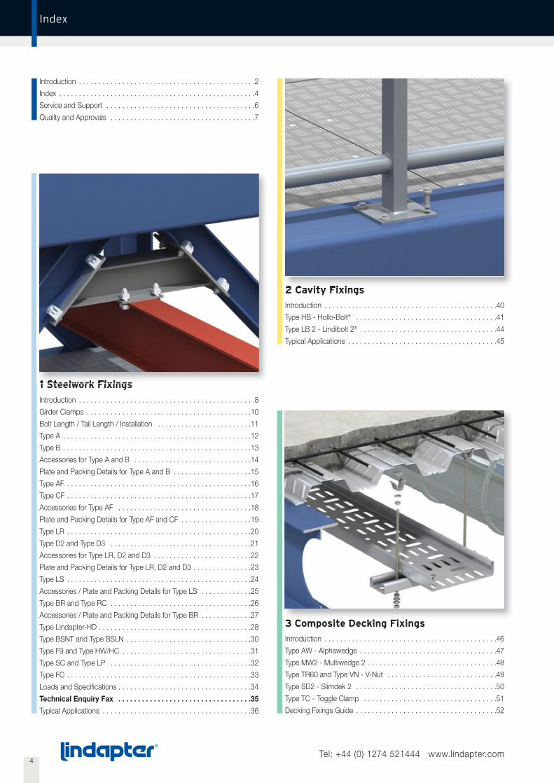
Index
1 Steelwork Fixings
Introduction . . . . . . . . . . . . . . . . . . . . . . . . . . . . . . . . . . . . . . . . . . . . .8
Girder Clamps . . . . . . . . . . . . . . . . . . . . . . . . . . . . . . . . . . . . . . . . . .10
Bolt Length / Tail Length / Installation . . . . . . . . . . . . . . . . . . . . . . . .11
Type A . . . . . . . . . . . . . . . . . . . . . . . . . . . . . . . . . . . . . . . . . . . . . . . .12
Type B . . . . . . . . . . . . . . . . . . . . . . . . . . . . . . . . . . . . . . . . . . . . . . . .13
Accessories for Type A and B . . . . . . . . . . . . . . . . . . . . . . . . . . . . . .14
Plate and Packing Details for Type A and B . . . . . . . . . . . . . . . . . . . .15
Type AF . . . . . . . . . . . . . . . . . . . . . . . . . . . . . . . . . . . . . . . . . . . . . . .16
Type CF . . . . . . . . . . . . . . . . . . . . . . . . . . . . . . . . . . . . . . . . . . . . . . .17
Accessories for Type AF . . . . . . . . . . . . . . . . . . . . . . . . . . . . . . . . . .18
Plate and Packing Details for Type AF and CF . . . . . . . . . . . . . . . . . .19
Type LR . . . . . . . . . . . . . . . . . . . . . . . . . . . . . . . . . . . . . . . . . . . . . . .20
Type D2 and Type D3 . . . . . . . . . . . . . . . . . . . . . . . . . . . . . . . . . . . .21
Accessories for Type LR, D2 and D3 . . . . . . . . . . . . . . . . . . . . . . . . .22
Plate and Packing Details for Type LR, D2 and D3 . . . . . . . . . . . . . . .23
Type LS . . . . . . . . . . . . . . . . . . . . . . . . . . . . . . . . . . . . . . . . . . . . . . .24
Accessories / Plate and Packing Details for Type LS . . . . . . . . . . . . .25
Type BR and Type RC . . . . . . . . . . . . . . . . . . . . . . . . . . . . . . . . . . . .26
Accessories / Plate and Packing Details for Type BR . . . . . . . . . . . . .27
Type Lindapter-HD . . . . . . . . . . . . . . . . . . . . . . . . . . . . . . . . . . . . . . .28
Type BSNT and Type BSLN . . . . . . . . . . . . . . . . . . . . . . . . . . . . . . . .30
Type F9 and Type HW/HC . . . . . . . . . . . . . . . . . . . . . . . . . . . . . . . . .31
Type SC and Type LP . . . . . . . . . . . . . . . . . . . . . . . . . . . . . . . . . . . .32
Type FC . . . . . . . . . . . . . . . . . . . . . . . . . . . . . . . . . . . . . . . . . . . . . . .33
Loads and Specifications . . . . . . . . . . . . . . . . . . . . . . . . . . . . . . . . . .34
Technical Enquiry Fax . . . . . . . . . . . . . . . . . . . . . . . . . . . . . . . . . .35
Typical Applications . . . . . . . . . . . . . . . . . . . . . . . . . . . . . . . . . . . . . .36
Introduction . . . . . . . . . . . . . . . . . . . . . . . . . . . . . . . . . . . . . . . . . . . . .2
Index . . . . . . . . . . . . . . . . . . . . . . . . . . . . . . . . . . . . . . . . . . . . . . . . . .4
Service and Support . . . . . . . . . . . . . . . . . . . . . . . . . . . . . . . . . . . . . .6
Quality and Approvals . . . . . . . . . . . . . . . . . . . . . . . . . . . . . . . . . . . . .7
2 Cavity Fixings
Introduction . . . . . . . . . . . . . . . . . . . . . . . . . . . . . . . . . . . . . . . . . . . .40
Type HB - Hollo-Bolt® . . . . . . . . . . . . . . . . . . . . . . . . . . . . . . . . . . . .41
Type LB 2 - Lindibolt 2® . . . . . . . . . . . . . . . . . . . . . . . . . . . . . . . . . . .44
Typical Applications . . . . . . . . . . . . . . . . . . . . . . . . . . . . . . . . . . . . . .45
3 Composite Decking Fixings
Introduction . . . . . . . . . . . . . . . . . . . . . . . . . . . . . . . . . . . . . . . . . . . .46
Type AW - Alphawedge . . . . . . . . . . . . . . . . . . . . . . . . . . . . . . . . . . .47
Type MW2 - Multiwedge 2 . . . . . . . . . . . . . . . . . . . . . . . . . . . . . . . . .48
Type TR60 and Type VN - V-Nut . . . . . . . . . . . . . . . . . . . . . . . . . . . .49
Type SD2 - Slimdek 2 . . . . . . . . . . . . . . . . . . . . . . . . . . . . . . . . . . . .50
Type TC - Toggle Clamp . . . . . . . . . . . . . . . . . . . . . . . . . . . . . . . . . .51
Decking Fixings Guide . . . . . . . . . . . . . . . . . . . . . . . . . . . . . . . . . . . .52
5Tel: +44 (0) 1274 521444 www.lindapter.com
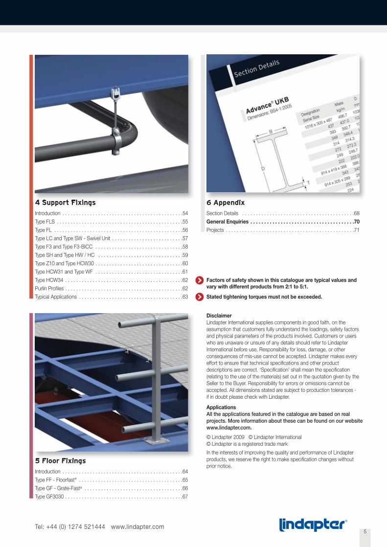
4 Support Fixings
Introduction . . . . . . . . . . . . . . . . . . . . . . . . . . . . . . . . . . . . . . . . . . . .54
Type FLS . . . . . . . . . . . . . . . . . . . . . . . . . . . . . . . . . . . . . . . . . . . . . .55
Type FL . . . . . . . . . . . . . . . . . . . . . . . . . . . . . . . . . . . . . . . . . . . . . . .56
Type LC and Type SW - Swivel Unit . . . . . . . . . . . . . . . . . . . . . . . . . .57
Type F3 and Type F3-BICC . . . . . . . . . . . . . . . . . . . . . . . . . . . . . . . .58
Type SH and Type HW / HC . . . . . . . . . . . . . . . . . . . . . . . . . . . . . . .59
Type Z10 and Type HCW30 . . . . . . . . . . . . . . . . . . . . . . . . . . . . . . . .60
Type HCW31 and Type WF . . . . . . . . . . . . . . . . . . . . . . . . . . . . . . . .61
Type HCW34 . . . . . . . . . . . . . . . . . . . . . . . . . . . . . . . . . . . . . . . . . . .62
Purlin Profiles . . . . . . . . . . . . . . . . . . . . . . . . . . . . . . . . . . . . . . . . . . .62
Typical Applications . . . . . . . . . . . . . . . . . . . . . . . . . . . . . . . . . . . . . .63
5 Floor Fixings
Introduction . . . . . . . . . . . . . . . . . . . . . . . . . . . . . . . . . . . . . . . . . . . .64
Type FF - Floorfast® . . . . . . . . . . . . . . . . . . . . . . . . . . . . . . . . . . . . . .65
Type GF - Grate-Fast® . . . . . . . . . . . . . . . . . . . . . . . . . . . . . . . . . . . .66
Type GF3030 . . . . . . . . . . . . . . . . . . . . . . . . . . . . . . . . . . . . . . . . . . .67
6 Appendix
Section Details . . . . . . . . . . . . . . . . . . . . . . . . . . . . . . . . . . . . . . . . .68
General Enquiries . . . . . . . . . . . . . . . . . . . . . . . . . . . . . . . . . . . . . .70
Projects . . . . . . . . . . . . . . . . . . . . . . . . . . . . . . . . . . . . . . . . . . . . . . .71
DisclaimerLindapter International supplies components in good faith, on theassumption that customers fully understand the loadings, safety factorsand physical parameters of the products involved. Customers or userswho are unaware or unsure of any details should refer to LindapterInternational before use. Responsibility for loss, damage, or otherconsequences of mis-use cannot be accepted. Lindapter makes everyeffort to ensure that technical specifications and other productdescriptions are correct. ‘Specification’ shall mean the specification(relating to the use of the materials) set out in the quotation given by theSeller to the Buyer. Responsibility for errors or omissions cannot beaccepted. All dimensions stated are subject to production tolerances -if in doubt please check with Lindapter.
ApplicationsAll the applications featured in the catalogue are based on realprojects. More information about these can be found on our websitewww.lindapter.com.
© Lindapter 2009 © Lindapter International© Lindapter is a registered trade mark
In the interests of improving the quality and performance of Lindapterproducts, we reserve the right to make specification changes withoutprior notice.
Factors of safety shown in this catalogue are typical values andvary with different products from 2:1 to 5:1.
Stated tightening torques must not be exceeded.

Bridge refurbishment:Due to the age and condition of the structure the use of welded shearstuds was not possible. Instead modified Hollo-Bolts® were used whichenabled the bridge deck refurbishment to be completed on time and tospecification.
For further information regarding this project see websitewww.lindapter.com.
6Tel: +44 (0) 1274 521444 www.lindapter.com
To meet the needs of a fast changing world Lindapter’s Research andDevelopment Department works to develop new generic products.The team is supported by the latest computer aided design (CAD)techniques such as 3D modelling, rapid prototyping and finite elementanalysis; new products are tested in house on Lindapter’s own 1,000kNhydraulic test machine.
This unique technical expertise is supported by Lindapter’s collaborationwith respected companies and organisations such as Corus, Mannesmann,The Steel Construction Institute, CIDECT as well as many leadinguniversities and approval bodies.
Service and Support
Research and Development
Engineered SolutionsDeveloping products that meet the needs of a particular project isanother Lindapter strength.
The service offered to clients includes:
• Design and development of custom products for unique projects
• Individual test runs and reports
• Detailed drawings and/or solid models
• Full strength and performance analysis
• Trial runs and on site consultation
Customer Technical SupportFor our existing product range Lindapter’s Technical Sales and SupportDepartment offers customers full support for any project, large or small;this free of charge service includes:
• Assembly solutions optimised for cost and performance
• Load analysis on Lindapter connections
• 2D AutoCAD and 3D SolidWorks drawings
• Bills of Materials
• Coating and corrosion recommendations
• On site technical advice and support
• Contractor training
• CPD Presentations
Sample Project
Special Hollo-Bolt®
Seedhill Bridge, Lancashire, England
Bespoke solutionfor sign fixings
Standard Hollo-Bolt®

7Tel: +44 (0) 1274 521444 www.lindapter.com
Product quality is one of the main life linesof the Lindapter philosophy, the entirecompany is particularly dedicated to thisaspect. Lindapter has been accredited toBS EN ISO 9001 since 1986.
Quality and Approvals
Quality
Lindapter has been trading internationally for many years respectingthe market differences around the world. The relevant internationalauthorities have granted many product approvals over time.The catalogue refers to them product by product.
Approvals for construction
The Deutsches Institut für Bautechnik, Berlin is a bodywhich approves products and materials for use instructural engineering applications in the constructionand civil engineering industries in Germany.
Lloyds Register Type Approved products have beensubjected to tensile, frictional, shear, vibration andshock tests, witnessed and verified by LloydsRegister.
The TÜV is the certifying authority for safety,quality and environmental protection in Germany.
Det Norske Veritas has approved the use of Lindapterproducts in lifting applications. This includes their useon both mobile and fixed offshore installations.
Approvals for sprinkler products
The American Insurance Association, Factory Mutual,offers an approval which is recognised by the fireprotection industry world-wide.
Verband der Schadenversicherer e.V. is a Germaninsurance association who also offers a rigorousapproval for products used in the fire protectionindustry.
These approvals serve to reinforce Lindapter’s extensive in-housetesting procedures. Lindapter products are tested so that the user canbe confident whether specifying or using that Lindapter products willperform as per the information detailed in this catalogue. Loadspublished are the product safe working loads, taking into account afactor of safety.
Lindapter products are delivered as standard either bright zinc platedor hot dip galvanised. Various other coatings and alternative materialsare available upon request for most products including:
• Sheradising
• Mechanical galvanising
• Plastic coating
• Special paint coating
Lindapter is a member of the following organisations:
Approvals
Q 05143
Corrosion Protection
British ConstructionalSteelwork Association
The Steel ConstructionInstitute
The Building Services Researchand Information Association
• Delta seal
• Delta tone
• Sheraplex
• Stainless steel
8
9
Steelwork Fixings 1
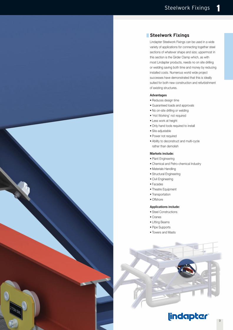
Steelwork FixingsLindapter Steelwork Fixings can be used in a wide
variety of applications for connecting together steel
sections of whatever shape and size; uppermost in
this section is the Girder Clamp which, as with
most Lindapter products, needs no on site drilling
or welding saving both time and money by reducing
installed costs. Numerous world wide project
successes have demonstrated that this is ideally
suited for both new construction and refurbishment
of existing structures.
Advantages
• Reduces design time
• Guaranteed loads and approvals
• No on-site drilling or welding
• ‘Hot Working’ not required
• Less work at height
• Only hand tools required to install
• Site adjustable
• Power not required
• Ability to deconstruct and multi-cycle
rather than demolish
Markets include:
• Plant Engineering
• Chemical and Petro-chemical Industry
• Materials Handling
• Structural Engineering
• Civil Engineering
• Facades
• Theatre Equipment
• Transportation
• Offshore
Applications include:
• Steel Constructions
• Cranes
• Lifting Beams
• Pipe Supports
• Towers and Masts

10Tel: +44 (0) 1274 521444 www.lindapter.com
Steelwork FixingsGirder Clamps 1
1
2
3
4
5
6
7
Components of a Girder Clamp1. Standard Grade 8 Hex Nut
2. Standard Hardened Washer
3. Lindapter ClampDependent on the application different clamps could be used i.e.Types A, B, BR, AF, LR, LS, D2 or D3.
4. Packing PieceIn combination with the clamps mentioned above these partsincrease the tail length to enable the product to sit correctly on thebeam.
5. Location Plate (can be supplied if required)This is an essential part of the girder clamp assembly that enablesall the components to be located in the correct position. The holecentres and plate thickness are calculated to suit the individualapplication.
6. Lindapter ClampThis can be of a similar type as 3 (above), although certain productsare designed to specifically work together i.e. A + B.
7. Standard Grade 8.8 Hex Bolt or Setscrew
LoadsThe table beneath shows tensile and frictional load capabilities for astandard four bolt Girder Clamp using 4 bolts and 8 clamps at a 90°crossover angle. Lindapter is only too pleased to carry out all design workfor individual connections free of charge based on the following details:
• Load per connection• Size and type of both beams• Angle of crossover• Distance between beams• Inclination of beams
ApprovalsAll approvals apply to Girder Clamps using types A and B only, in sizes from M12 to M24 Further information is available upon request.
All loads are based on actual test data having a factor of safety for friction against slip and for tensile against ultimate failure(typically 5:1). Use of lower safety factor is not recommended.
Clamps Types A, B, BR, LR Type AFBolt size M12 M16 M20 M24 M24 M24Bolt grade 8.8 8.8 8.8 8.8 8.8 10.9Tensile / for 4 bolts kN 23.2 29.2 59.0 78.8 160.0 250.01)
Friction / for 4 bolts kN 1.4 3.0 6.0 9.0 60.02) 70.02)
Torque Nm 69 147 285 491 800 10001) Factor of safety 3.2:1
2) Factor of safety 2:1
11Tel: +44 (0) 1274 521444 www.lindapter.com
Steelwork FixingsBolt Length / Tail Length / Installation 1
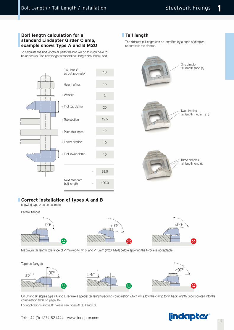
Bolt length calculation for astandard Lindapter Girder Clamp,example shows Type A and B M20To calculate the bolt length all parts the bolt will go through have tobe added up. The next longer standard bolt length should be used.
On 6º and 8º slopes types A and B require a special tail length/packing combination which will allow the clamp to tilt back slightly (incorporated into thecombination table on page 15).
For applications above 8° please see types AF, LR and LS.
Maximum tail length tolerance of -1mm (up to M16) and -1.5mm (M20, M24) before applying the torque is acceptable.
Tail lengthThe different tail length can be identified by a code of dimplesunderneath the clamps.
Correct installation of types A and B showing type A as an example
Parallel flanges
Tapered flanges
Height of nut
+ Washer
+ T of top clamp
+ Top section
+ Plate thickness
+ Lower section
+ T of lower clamp
Next standardbolt length
=
=
0.5 · bolt Øas bolt protrusion
90º <90º>90º
<_5º 5-8º<90º
One dimple:tail length short (s)
Two dimples:tail length medium (m)
Three dimples:tail length long (l )
90º
10
16
3
20
12.5
12
10
10
93.5
100.0

12Tel: +44 (0) 1274 521444 www.lindapter.com
Steelwork FixingsType A 1
Steelwork clamp with recessed top to hold the bolt head captive whilstthe nut is tightened. The skirt prevents the clamp rotating duringinstallation. Suitable for flanges up to 8°.The clamp is installed correctly when the area ‘K’ grips the flange.The tail must be chosen to suit the thickness of the flange beinggripped. For correct tail length/packing combinations please seepage 15.
For higher loads the type AF should be used (see page 16).
Order example: A16 medium HDG
Type AMalleable iron, bright zinc plated / hot dip galvanised
Typical Applications(see also page 36-39)
Recess
Tail
Nose
Skirt
V
Y
Safe Working Loads DimensionsProduct Bolt 8.8 (5:1 Factor of Safety) Tail Length VCode Z Tensile / 1 Bolt Frictional / 2 Bolts Torque Y X short medium long T Width
kN kN Nm mm mm mm mm mm mm mmA08 M8 1.0 - 6 16 8 - 4 - 4 20
A10 M10 1.5 - 20 20 11 4 5 7 5 26
A12 M12 5.8 0.7 69 26 13 4.5 6 9.5 6 29
A16 M16 7.3 1.5 147 30 16 5.5 8 11 8 36
A20 M20 14.7 3 285 36 19 7 10 12.5 10 46
A24 M24 19.7 4.5 491 48 25 9 12 16 12 55
X
Z
T
Clamping Area K
13Tel: +44 (0) 1274 521444 www.lindapter.com
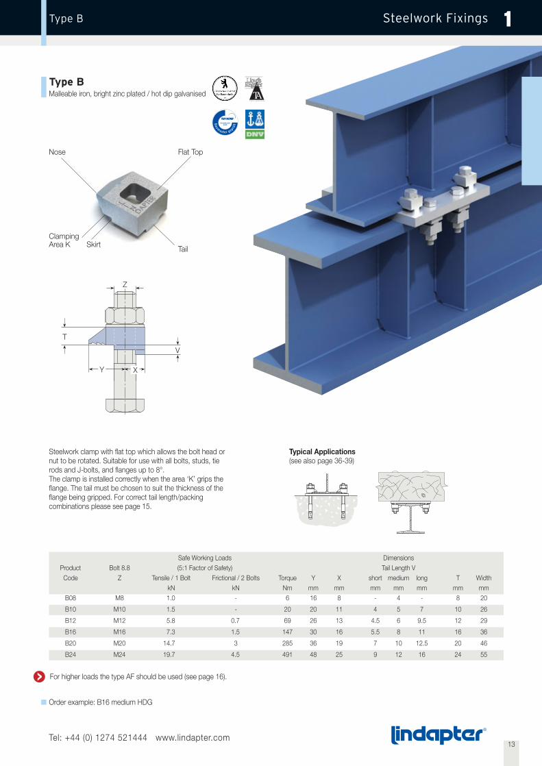
Type B 1
Steelwork clamp with flat top which allows the bolt head ornut to be rotated. Suitable for use with all bolts, studs, tierods and J-bolts, and flanges up to 8°.The clamp is installed correctly when the area ‘K’ grips theflange. The tail must be chosen to suit the thickness of theflange being gripped. For correct tail length/packingcombinations please see page 15.
Type BMalleable iron, bright zinc plated / hot dip galvanised
Order example: B16 medium HDG
Steelwork Fixings
Tail
Nose Flat Top
T
Z
Safe Working Loads DimensionsProduct Bolt 8.8 (5:1 Factor of Safety) Tail Length VCode Z Tensile / 1 Bolt Frictional / 2 Bolts Torque Y X short medium long T Width
kN kN Nm mm mm mm mm mm mm mmB08 M8 1.0 - 6 16 8 - 4 - 8 20
B10 M10 1.5 - 20 20 11 4 5 7 10 26
B12 M12 5.8 0.7 69 26 13 4.5 6 9.5 12 29
B16 M16 7.3 1.5 147 30 16 5.5 8 11 16 36
B20 M20 14.7 3 285 36 19 7 10 12.5 20 46
B24 M24 19.7 4.5 491 48 25 9 12 16 24 55
Typical Applications(see also page 36-39)
V
XY
SkirtClampingArea K
For higher loads the type AF should be used (see page 16).
14Tel: +44 (0) 1274 521444 www.lindapter.com
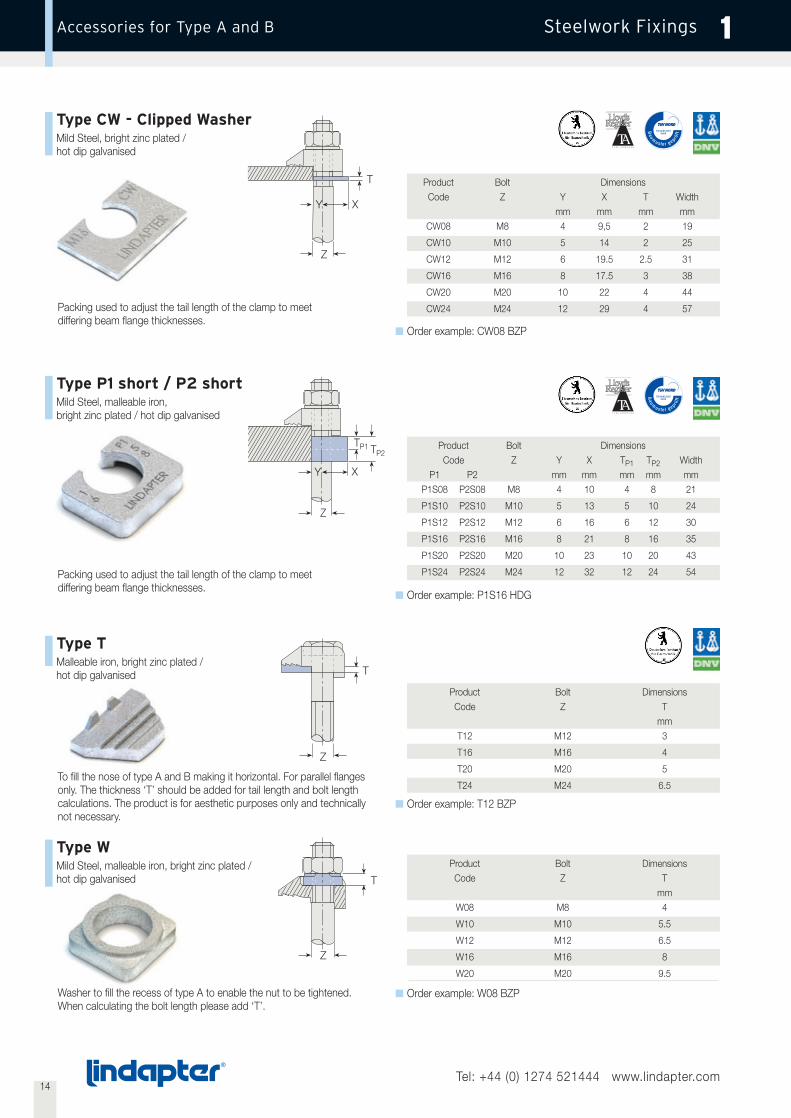
Steelwork FixingsAccessories for Type A and B 1
Type CW - Clipped WasherMild Steel, bright zinc plated /hot dip galvanised
Type P1 short / P2 shortMild Steel, malleable iron,bright zinc plated / hot dip galvanised
Packing used to adjust the tail length of the clamp to meetdiffering beam flange thicknesses.
Packing used to adjust the tail length of the clamp to meetdiffering beam flange thicknesses.
To fill the nose of type A and B making it horizontal. For parallel flangesonly. The thickness ‘T’ should be added for tail length and bolt lengthcalculations. The product is for aesthetic purposes only and technicallynot necessary.
T
Z
Order example: CW08 BZP
Type TMalleable iron, bright zinc plated /hot dip galvanised
Type WMild Steel, malleable iron, bright zinc plated /hot dip galvanised
Order example: P1S16 HDG
Order example: T12 BZP
Order example: W08 BZP
Product Bolt DimensionsCode Z T
mmW08 M8 4
W10 M10 5.5
W12 M12 6.5
W16 M16 8
W20 M20 9.5
TP1 TP2
Z
Y X
T
Z
T
Z
Product Bolt DimensionsCode Z T
mmT12 M12 3
T16 M16 4
T20 M20 5
T24 M24 6.5
Product Bolt DimensionsCode Z Y X TP1 TP2 Width
P1 P2 mm mm mm mm mmP1S08 P2S08 M8 4 10 4 8 21
P1S10 P2S10 M10 5 13 5 10 24
P1S12 P2S12 M12 6 16 6 12 30
P1S16 P2S16 M16 8 21 8 16 35
P1S20 P2S20 M20 10 23 10 20 43
P1S24 P2S24 M24 12 32 12 24 54
Product Bolt DimensionsCode Z Y X T Width
mm mm mm mmCW08 M8 4 9,5 2 19
CW10 M10 5 14 2 25
CW12 M12 6 19.5 2.5 31
CW16 M16 8 17.5 3 38
CW20 M20 10 22 4 44
CW24 M24 12 29 4 57
XY
Washer to fill the recess of type A to enable the nut to be tightened.When calculating the bolt length please add ‘T’.
15Tel: +44 (0) 1274 521444 www.lindapter.com
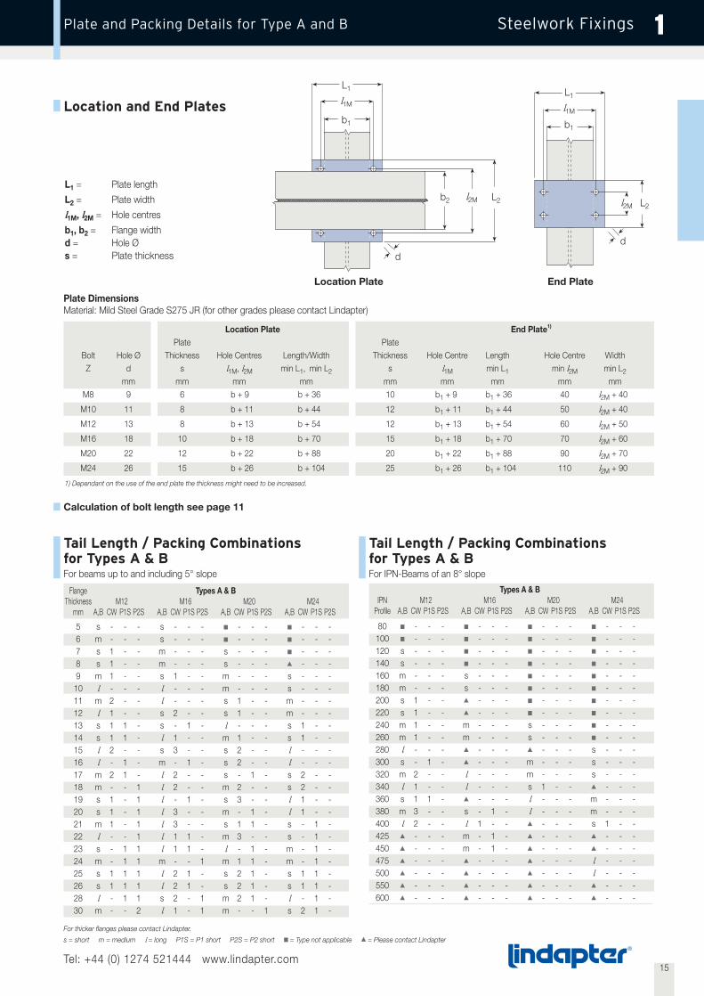
Steelwork FixingsPlate and Packing Details for Type A and B 1
Tail Length / Packing Combinations for Types A & BFor beams up to and including 5° slope
Plate DimensionsMaterial: Mild Steel Grade S275 JR (for other grades please contact Lindapter)
Calculation of bolt length see page 11
Tail Length / Packing Combinationsfor Types A & BFor IPN-Beams of an 8° slope
Types A & BIPN M12 M16 M20 M24
Profile A,B CW P1S P2S A,B CW P1S P2S A,B CW P1S P2S A,B CW P1S P2S
80 ■ - - - ■ - - - ■ - - - ■ - - -100 ■ - - - ■ - - - ■ - - - ■ - - -120 s - - - ■ - - - ■ - - - ■ - - -140 s - - - ■ - - - ■ - - - ■ - - -160 m - - - s - - - ■ - - - ■ - - -180 m - - - s - - - ■ - - - ■ - - -200 s 1 - - ▲ - - - ■ - - - ■ - - -220 s 1 - - ▲ - - - ■ - - - ■ - - -240 m 1 - - m - - - s - - - ■ - - -260 m 1 - - m - - - s - - - ■ - - -280 l - - - ▲ - - - ▲ - - - s - - -300 s - 1 - ▲ - - - m - - - s - - -320 m 2 - - l - - - m - - - s - - -340 l 1 - - l - - - s 1 - - ▲ - - -360 s 1 1 - ▲ - - - l - - - m - - -380 m 3 - - s - 1 - l - - - m - - -400 l 2 - - l 1 - - ▲ - - - s 1 - -425 ▲ - - - m - 1 - ▲ - - - ▲ - - -450 ▲ - - - m - 1 - ▲ - - - ▲ - - -475 ▲ - - - ▲ - - - ▲ - - - l - - -500 ▲ - - - ▲ - - - ▲ - - - l - - -550 ▲ - - - ▲ - - - ▲ - - - ▲ - - -600 ▲ - - - ▲ - - - ▲ - - - ▲ - - -
Flange Types A & BThickness M12 M16 M20 M24
mm A,B CW P1S P2S A,B CW P1S P2S A,B CW P1S P2S A,B CW P1S P2S
5 s - - - s - - - ■ - - - ■ - - -6 m - - - s - - - ■ - - - ■ - - -7 s 1 - - m - - - s - - - ■ - - -8 s 1 - - m - - - s - - - ▲ - - -9 m 1 - - s 1 - - m - - - s - - -10 l - - - l - - - m - - - s - - -11 m 2 - - l - - - s 1 - - m - - -12 l 1 - - s 2 - - s 1 - - m - - -13 s 1 1 - s - 1 - l - - - s 1 - -14 s 1 1 - l 1 - - m 1 - - s 1 - -15 l 2 - - s 3 - - s 2 - - l - - -16 l - 1 - m - 1 - s 2 - - l - - -17 m 2 1 - l 2 - - s - 1 - s 2 - -18 m - - 1 l 2 - - m 2 - - s 2 - -19 s 1 - 1 l - 1 - s 3 - - l 1 - -20 s 1 - 1 l 3 - - m - 1 - l 1 - -21 m 1 - 1 l 3 - - s 1 1 - s - 1 -22 l - - 1 l 1 1 - m 3 - - s - 1 -23 s - 1 1 l 1 1 - l - 1 - m - 1 -24 m - 1 1 m - - 1 m 1 1 - m - 1 -25 s 1 1 1 l 2 1 - s 2 1 - s 1 1 -26 s 1 1 1 l 2 1 - s 2 1 - s 1 1 -28 l - 1 1 s 2 - 1 m 2 1 - l - 1 -30 m - - 2 l 1 - 1 m - - 1 s 2 1 -
Location Plate End Plate1)
Plate PlateBolt Hole Ø Thickness Hole Centres Length/Width Thickness Hole Centre Length Hole Centre Width
Z d s l1M, l2M min L1, min L2 s l1M min L1 min l2M min L2
mm mm mm mm mm mm mm mm mmM8 9 6 b + 9 b + 36 10 b1 + 9 b1 + 36 40 l2M + 40
M10 11 8 b + 11 b + 44 12 b1 + 11 b1 + 44 50 l2M + 40
M12 13 8 b + 13 b + 54 12 b1 + 13 b1 + 54 60 l2M + 50
M16 18 10 b + 18 b + 70 15 b1 + 18 b1 + 70 70 l2M + 60
M20 22 12 b + 22 b + 88 20 b1 + 22 b1 + 88 90 l2M + 70
M24 26 15 b + 26 b + 104 25 b1 + 26 b1 + 104 110 l2M + 90
1) Dependant on the use of the end plate the thickness might need to be increased.
For thicker flanges please contact Lindapter.
s = short m = medium l = long P1S = P1 short P2S = P2 short ■ = Type not applicable ▲ = Please contact Lindapter
Location and End Plates
L1 = Plate length
L2 = Plate width
l1M, l2M = Hole centres
b1, b2 = Flange widthd = Hole Øs = Plate thickness
L1
l1M
b1
L1
l1M
b1
L2 L2l2M l2M
b2
d
d
Location Plate End Plate

16Tel: +44 (0) 1274 521444 www.lindapter.com
Steelwork FixingsType AF 1
Tail
Nose
Skirt
Recess
Without washer: For bolt grade 8.8
With washer Type AFW
With washer inverted Type AFWfor bolt grade 10.9 with larger hexagons(M12 - M20)
V
XY
T
Z
Safe Working Loads(5:1) Factor of Safety (2:1) Dimensions
Product Bolt Tensile / 1 Bolt Frictional1) / 2 Bolts Tail Length V TCode Z Grade Painted Steelwork2) Galv. Steelwork Torque Y X short medium Type AF Type AF with AFW Width
kN kN kN Nm mm mm mm mm mm mm mmAF12 M12 8.8 8.5 3.4 3.9 90 29 27 5 12.5 17 22 39
AF16 M16 8.8 16.0 8.0 10.0 240 35 37 8 15 22 27 49
AF20 M20 8.8 26.3 13.0 16.0 470 40 39 10 18 25 31 56
AF24 M24 8.8 40.0 24.0 30.0 800 48 60 15 30 32 42 82
AF12 M12 10.94) 10.0 4.0 5.2 130 29 27 5 12.5 17 22 39
AF16 M16 10.94) 19.5 11.0 12.0 300 35 37 8 15 22 27 49
AF20 M20 10.94) 30.0 20.0 25.0 647 40 39 10 18 25 31 56
AF24 M24 10.94) 62.53) 28.0 35.0 1000 48 60 15 30 32 42 82
1) Frictional Load figures are based on Type AF and Location plates in hot dip galvanised finish2) Shot blast and painted steelwork3) 3.2:1 factor of safety4) For HR or HV bolts (hot dip galvanised and lubricated) please refer to manufacturers’ recommendation for torque figures.
High friction clamp with recessed top to hold bolt head captive whilstthe nut is tightened. Can be combined with type CF. The skirt preventsthe clamp rotating during installation. The tail of the AF spans acrossslotted holes. For flanges up to 10°. Washer type AFW available(see illustration).
For correct tail length/packing combinations please see page 18.
Order example: AF12 short
Typical Applications(see also page 36-39)
Flat Top
Type AFSG iron, hot dip galvanised

17Tel: +44 (0) 1274 521444 www.lindapter.com
Steelwork FixingsType CF 1
Type CFSG iron, hot dip galvanised
Legs
NoseAnti-rotation markings
High friction clamp which hooks over flanges of I-beams, angles andchannels. Lindapter markings act as a unique anti-rotation device.Can be combined with all Lindapter Girder Clamp products includingtype AF.
Safe Working Loads(5:1) factor of safety (2:1)
Product Bolt 8.8 Tensile / 1 Bolt Frictional1) / 2 Bolts DimensionsCode Z Painted Steelwork2) Galv. Steelwork Torque Y X t T V Width
kN kN kN Nm mm mm mm mm mm mmCF12 M12 8.5 3.4 3.9 90 32 14 6 - 13 21 - 29 25 46
CF16 M16 16.0 8.0 10.0 240 44 18 8 - 16 25 - 33 32 56
CF20 M20 26.3 13.0 16.0 470 53 22 10 - 19 30 - 41 45 65
CF Combinations with other Lindapter ClampskN kN kN Nm
CF / A3) M12 5.8 0.7 0.7 69CF / A3) M16 7.3 1.5 1.7 147
CF / A3) M20 14.7 3 3.0 285
CF / AF M12 8.5 3.4 3.9 90
CF / AF M16 16.0 8.0 10.0 240
CF / AF M20 26.3 13.0 16.0 470
1) Frictional load figures are based on type CF and location plate in HDG finish2) Shot blast and painted steelwork3) Also applies to type B, BR, LR, D2 or D3
Order example: CF12
Typical Applications(see also page 36-39)
min T
X
V
Y
min t
max T
XY
max t
Z Z

18Tel: +44 (0) 1274 521444 www.lindapter.com
Steelwork FixingsAccessories for Type AF 1
Type AFCWMild Steel, hot dip galvanised
Order example: AF12CW
Product Bolt DimensionsCode Z Y X T Width
mm mm mm mmAF12CW M12 7 33 2 40
AF16CW M16 8 40 2 50
AF20CW M20 9.5 40.5 2 55
Packing used to adjust the tail length ofthe clamp to meet differing beam flangethicknesses; has a slight bend along itscentre line which flattens out duringinstallation.
Y X
T
Z
XT
Z
Type AFP1 / AFP2Mild Steel, hot dip galvanised
Order example: AF12P1Packing used to adjust the taillength of the clamp to meetdiffering beam flange thicknesses.
Type AFWSG iron, malleable iron, hot dip galvanised
Order example: AFW12
Product Bolt DimensionsCode Z T
mmAFW12 M12 5
AFW16 M16 5
AFW20 M20 6
AFW24 M24 10
Washer filling the recess of the type AF.
Additionally it features two projectionswhich, when the AFW is inverted, willcaptivate the larger hexagons of 10.9bolts. (M12 – M20 only). M24 version has no projections.
Z
Z
T
T
Y
Product Bolt DimensionsCode Z Y X TP1 TP2 Width
P1 P2 mm mm mm mm mmAF12P1 AF12P2 M12 7 33 5 10 40
AF16P1 AF16P2 M16 8 42 5 10 52
AF20P1 AF20P2 M20 9.5 45.5 5 10 56
AF24P1 AF24P2 M24 12 73 5 10 85

19Tel: +44 (0) 1274 521444 www.lindapter.com
Steelwork FixingsPlate and Packing Details for Type AF and CF 1
Tail Length / Packing Combinations for Types AFParallel flanges and beams of up to 10º slope
Flange Type AFThickness M12 M16 M20 M24
mm AF AFCW AFP1 AFP2 AF AFCW AFP1 AFP2 AF AFCW AFP1 AFP2 AF AFP1 AFP2
5 s - - - ■ - - - ■ - - - ■ - -6 s - - - ■ - - - ■ - - - ■ - -7 s 1 - - s - - - ■ - - - ■ - -8 s 1 - - s - - - ■ - - - ■ - -9 s 2 - - s - - - s - - - ■ - -10 s - 1 - s 1 - - s - - - ■ - -11 s 3 - - s 1 - - s - - - ■ - -12 s 1 1 - s 2 - - s 1 - - s - -13 m - - - s - 1 - s 1 - - s - -14 m 1 - - s 3 - - s 2 - - s - -15 s - - 1 m - - - s - 1 - s - -16 m 2 - - m - - - s 3 - - s - -17 m - 1 - m 1 - - m - - - s - -18 m - 1 - s - - 1 m - - - s 1 -19 m 1 1 - m - 1 - m - - - s 1 -20 s - 1 1 m - 1 - m 1 - - s 1 -21 m 2 1 - m - 1 - m 1 - - s 1 -22 m 2 1 - m 1 1 - m 2 - - s 1 -23 m - - 1 m 1 1 - m - 1 - s - 124 m 1 - 1 m - - 1 m 1 1 - s - 125 s - - 2 m - - 1 m 1 1 - s - 126 m 2 - 1 m - - 1 s 1 1 1 s - 127 m 2 - 1 m 1 - 1 s 1 1 1 m - -
Flange Type AFThickness M12 M16 M20 M24
mm AF AFCW AFP1 AFP2 AF AFCW AFP1 AFP2 AF AFCW AFP1 AFP2 AF AFP1 AFP2
28 m - 1 1 s - - 2 m - - 1 m - -29 m 1 1 1 m - 1 1 m - - 1 m - -30 s - 1 2 m - 1 1 m 1 - 1 m - -31 s - 1 2 m - 1 1 m 1 - 1 m - -32 m - - 2 m 1 1 1 m - 1 1 m 1 -33 m - - 2 m 1 1 1 m - 1 1 m 1 -34 m 1 - 2 m - - 2 m - 1 1 m 1 -35 s - - 3 m - - 2 s - 1 2 m 1 -36 s - - 3 m - - 2 m 1 1 1 m 1 -37 m - 1 2 m 1 - 2 m - - 2 m 1 -38 m - 1 2 s - - 3 m - - 2 m - 139 m 1 1 2 m - 1 2 m - - 2 m - 140 s - 1 3 m - 1 2 m 1 - 2 m - 141 s - 1 3 m - 1 2 m 1 - 2 m - 142 m - - 3 m 1 1 2 m - 1 2 m - 143 m - - 3 s - 1 3 m - 1 2 m 1 144 m 1 - 3 m - - 3 m - 1 2 m 1 145 s - - 4 m - - 3 m 1 1 2 m 1 146 s - - 4 m - - 3 m 1 1 2 m 1 147 m - 1 3 m 1 - 3 m - - 3 m 1 148 m - 1 3 s - - 4 m - - 3 m - 249 s - 1 4 m - 1 3 m - - 3 m - 250 s - 1 4 m - 1 3 m 1 - 3 m - 2
Calculation of bolt length see page 11
Plate DimensionsMaterial: Mild Steel Grade S355 JR (for other grades please contact Lindapter)
Location Plate End Plate1)
Plate PlateBolt Hole Ø Thickness Hole Centres Length/Width Thickness Hole Centre Length Hole Centre Width
Z d s l1M, l2M min L1, min L2 s l1M min L1 min l2M min L2
mm mm mm mm mm mm mm mm mmM12 13 10 b + 13 b + 90 15 b1 + 13 b1 + 90 80 l2M + 80
M16 18 15 b + 18 b + 110 25 b1 + 18 b1 + 110 100 l2M + 100
M20 22 20 b + 22 b + 130 30 b1 + 22 b1 + 130 180 l2M + 180
M24 26 25 b + 26 b + 180 40 b1 + 26 b1 + 180 200 l2M + 200
1) Dependant on the use of the end plate the thickness might need to be increased.
2) For combinations of Type CF with A, B and BR see page 15 and for types D2, D3 and LR see page 23.
Location and End Plates
L1 = Plate length
L2 = Plate width
l1M, l2M = Hole centres
b1, b2 = Flange widthd = Hole Øs = Plate thickness
L1
l1M
b1
L1
l1M
b1
L2 L2l2M l2M
b2
dd
Location Plate End Plate
s = short m = medium ■ = Type not applicable

20Tel: +44 (0) 1274 521444 www.lindapter.com
Steelwork FixingsType LR 1
Type LRMalleable iron, bright zinc plated / hot dip galvanised
Saddle
Slot
TailClip
Nose
max Y min X
Z
Z
Leg
Safe Working LoadsProduct Bolt 8.8 (5:1 Factor of Safety) Clamping Range Dimensions
Code Z Tensile / 1 Bolt Frictional / 2 Bolts Torque V Y X T Width with SaddlekN kN Nm mm mm mm mm mm
LR10 M10 1.5 - 20 3 - 10 21 - 24 24 - 26 21 - 24 33
LR12 M12 5.8 0.7 69 3 - 12 26 - 29 25 - 31 25 - 29 39
LR16 M16 7.3 1.5 147 3 - 16 30 - 35 34 - 37 30 - 36 46
LR20 M20 14.7 3 285 3 - 20 42 - 49 46 - 51 41 - 48 57
LR24 M24 19.7 4.5 491 3 - 24 47 - 57 52 - 58 44 - 54 76
Self adjusting clamp for various flange thicknesses and slopes upto 15°. The leg of the saddle prevents the clamp rotating duringinstallation. The LR tail spans slotted holes. For thicker flangespackings P1 long and P2 long are available. For correct taillength/packing combinations please see page 23.
Order example: LR10 BZP
Typical Applications(see also page 36-39)
max T
min V
max V
min T
min Y max X
21Tel: +44 (0) 1274 521444 www.lindapter.com
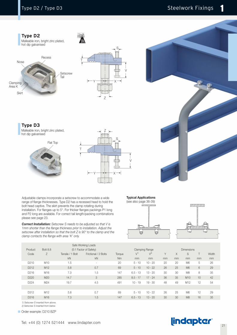
Steelwork FixingsType D2 / Type D3 1
Adjustable clamps incorporate a setscrew to accommodate a widerange of flange thicknesses. Type D2 has a recessed head to hold thebolt head captive. The skirt prevents the clamp rotating duringinstallation. For flanges up to 5°. For thicker flanges packings P1 longand P2 long are available. For correct tail length/packing combinationsplease see page 23.
Correct Installation: Setscrew S needs to be adjusted so that V is1mm shorter than the flange thickness prior to installation. Adjust thesetscrew after installation so that the bolt Z is 90° to the clamp and theclamp contacts the flange with area ‘K’ only.
Type D3Malleable iron, bright zinc plated,hot dip galvanised
Recess
Skirt
Nose
SetscrewTail
S
T
V
XY
Z
Z
T
S
ClampingArea K
Flat Top
Safe Working LoadsProduct Bolt 8.8 (5:1 Factor of Safety) Clamping Range DimensionsCode Z Tensile / 1 Bolt Frictional / 2 Bolts Torque V1) V2) Y X S T Width
kN kN Nm mm mm mm mm mm mm mmD210 M10 1.5 - 20 5 - 10 10 - 20 20 20 M6 5 26
D212 M12 5.8 0.7 69 5 - 10 10 - 22 26 25 M6 6 29
D216 M16 7.3 1.5 147 6.5 - 13 13 - 20 30 30 M8 8 35
D220 M20 14.7 3 285 8.5 - 17 17 - 24 36 35 M10 10 42
D224 M24 19.7 4.5 491 10 - 19 19 - 30 48 49 M12 12 54
D312 M12 5.8 0.7 69 5 - 10 10 - 22 26 25 M6 12 29
D316 M16 7.3 1.5 147 6.5 - 13 13 - 20 30 30 M8 16 35
1) Setscrew S inserted from above.2) Setscrew S inserted from below.
Typical Applications(see also page 36-39)
V
XY
Order example: D210 BZP
Type D2Malleable iron, bright zinc plated,hot dip galvanised

22Tel: +44 (0) 1274 521444 www.lindapter.com
Steelwork FixingsAccessories for Type LR, D2 and D3 1
Type P1 long / P2 longMild Steel, malleable iron, bright zinc plated / hot dip galvanised
Packing used to adjust the tail length ofthe clamp to meet differing beam flangethicknesses.
Order example: P1L10 BZP
Product Bolt DimensionsCode Z Y X TP1 TP2 Width
P1 P2 mm mm mm mm mmP1L10 P2L10 M10 5 24 5 10 24
P1L12 P2L12 M12 6 32 6 12 30
P1L16 P2L16 M16 8 40 8 16 35
P1L20 P2L20 M20 10 47 10 20 43
P1L24 P2L24 M24 12 64 12 24 54
Type WMild Steel, bright zinc plated /hot dip galvanised
Washer to fill the recess of type D2 toenable the nut to be tightened. Whencalculating the bolt length please add ‘T’.
Order example: W08 BZP
Product Bolt DimensionsCode Z T
mmW08 M8 4
W10 M10 5.5
W12 M12 6.5
W16 M16 8
W20 M20 9.5
T
Z
To fill the nose of type D2 and D3 making ithorizontal. For parallel flanges only.The thickness ‘T’ should be added for taillength and bolt length calculations. The productis for aesthetic purposes only and technicallynot necessary.
Type TMalleable iron, bright zinc plated /hot dip galvanised
Order example: T12 BZP
T
Z
Product Bolt DimensionsCode Z T
mmT12 M12 3
T16 M16 4
T20 M20 5
T24 M24 6.5
TP2TP1
Y X
Z

23Tel: +44 (0) 1274 521444 www.lindapter.com
Steelwork FixingsPlate and Packing Details for Type LR, D2 and D3 1
Calculation of bolt length see page 11
Tail Length / Packing Combinationsfor Type LRFor IPN-Beams of an 8° slope
P1L = P1 long P2L = P2 long ■ = Type not applicable
For thicker flanges please contact Lindapter.
Plate DimensionsMaterial: Mild Steel Grade S275 JR
Location Plate End Plate1)
Plate PlateBolt Hole Ø Thickness Hole Centres Length/Width Thickness Hole Centre Length Hole Centre Width
Z d s l1M, l2M min L1, min L2 s l1M min L1 min l2M min L2
mm mm mm mm mm mm mm mm mmM10 11 12 b + 11 b + 66 15 b1 + 11 b1 + 66 70 l2M + 50
M12 13 12 b + 13 b + 81 15 b1 + 13 b1 + 81 80 l2M + 60
M16 18 15 b + 18 b + 105 20 b1 + 18 b1 + 105 100 l2M + 70
M20 22 20 b + 22 b + 132 25 b1 + 22 b1 + 132 120 l2M + 90
M24 26 25 b + 26 b + 156 30 b1 + 26 b1 + 156 150 l2M + 110
1) Dependant on the use of the end plate the thickness might need to be increased.
Location and End Plates
L1 = Plate length
L2 = Plate width
l1M, l2M = Hole centres
b1, b2 = Flange widthd = Hole Øs = Plate thickness
L1
l1M
b1
L1
l1M
b1
L2 L2l2M l2M
b2
d
d
Location Plate End Plate
Type M 10 M 12 M 16 M 20 M 24Combinations Clamping RangeLR P1L P2L mm mm mm mm mm
1 - - 3 - 10 3 - 12 3 - 16 3 - 20 3 - 24
1 1 - 8 - 15 9 - 18 11 - 24 13 - 30 15 - 36
1 - 1 13 - 20 15 - 24 19 - 32 23 - 40 27 - 48
1 1 1 18 - 25 21 - 30 27 - 40 33 - 50 39 - 60
1 - 2 23 - 30 27 - 36 35 - 48 43 - 60 51 - 72
1 1 2 28 - 35 33 - 42 43 - 56 53 - 70 63 - 84
1 - 3 33 - 40 39 - 48 51 - 64 63 - 80 75 - 96
Tail Length / Packing Combinationsfor Type D2 & D3Parallel flanges and beams of up to 5° slope
Type M 10 M 12 M 16 M 20 M 24D2 D2 / D3 D2 / D3 D2 D2
Combinations Clamping RangeD P1L P2L mm mm mm mm mm
11) - - 5 - 10 5 - 10 6.5 - 13 8.5 - 17 10 - 19
1 - - 10 - 20 10 - 22 13 - 20 17 - 24 19 - 30
1 1 - 15 - 25 16 - 28 21 - 28 27 - 34 31 - 42
1 - 1 20 - 30 22 - 34 29 - 36 37 - 44 43 - 54
1 1 1 25 - 35 28 - 40 37 - 44 47 - 54 55 - 66
1 - 2 30 - 40 34 - 46 45 - 52 57 - 64 67 - 78
1 1 2 35 - 45 40 - 52 53 - 60 67 - 74 79 - 90
1 - 3 40 - 50 46 - 58 61 - 68 77 - 84 91 - 102
1) Setscrew S inverted.
IPN M10 M12 M16 M20 M24Profile LR P1L P2L LR P1L P2L LR P1L P2L LR P1L P2L LR P1L P2L
80 1 - - ■ - - ■ - - ■ - - ■ - -100 1 - - 1 - - ■ - - ■ - - ■ - -120 1 - - 1 - - 1 - - ■ - - ■ - -140 1 - - 1 - - 1 - - ■ - - ■ - -160 1 - - 1 - - 1 - - 1 - - ■ - -180 1 - - 1 - - 1 - - 1 - - ■ - -200 1 - - 1 - - 1 - - 1 - - ■ - -220 1 - - 1 - - 1 - - 1 - - 1 - -240 1 1 - 1 - - 1 - - 1 - - 1 - -260 1 1 - 1 - - 1 - - 1 - - 1 - -280 1 1 - 1 1 - 1 - - 1 - - 1 - -300 1 1 - 1 1 - 1 - - 1 - - 1 - -320 1 1 - 1 1 - 1 - - 1 - - 1 - -340 1 1 - 1 1 - 1 - - 1 - - 1 - -360 1 - 1 1 1 - 1 1 - 1 - - 1 - -380 1 - 1 1 1 - 1 1 - 1 - - 1 - -400 1 - 1 1 1 - 1 1 - 1 - - 1 - -425 1 - 1 1 - 1 1 1 - 1 1 - 1 - -450 1 - 1 1 - 1 1 1 - 1 1 - 1 - -475 1 1 1 1 - 1 1 1 - 1 1 - 1 - -500 1 1 1 1 - 1 1 1 - 1 1 - 1 - -550 1 1 1 1 1 1 1 - 1 1 1 - 1 - -600 ■ - - 1 1 1 1 - 1 1 1 - 1 1 -
Tail Length / Packing Combinationsfor Type LRParallel flanges

24Tel: +44 (0) 1274 521444 www.lindapter.com
Steelwork FixingsType LS 1
Type LSCast Stainless Steel equivalent to Grade 316
Tail
Nose
Self adjusting clamp for various flange thicknesses and slopes up to 10°.The special serrations on the tail prevent the clamp rotating duringinstallation. The LS tail spans over slotted holes.
Typical Applications(see also page 36-39)
Safe Working Load ClampingProduct Bolt A4-70 (5:1) Factor of Safety (2:1) Range DimensionsCode Z Tensile / 1 Bolt Frictional / 2 Bolts Torque V Y X T Width
kN kN Nm mm mm mm mm mmLS10 M10 3.0 1.5 40 3 - 15 17 - 19 18 - 24 16 - 21 38
LS12 M12 7.0 2.0 80 3 - 20 16 - 22 18 - 29 17 - 23 40
LS16 M16 10.0 3.0 200 3 - 25 22 - 25 27 - 37 20 - 28 55
LS20 M20 18.0 5.0 400 3 - 30 24 - 31 25 - 42 23 - 32 60
Order example: LS10
min Y max X
Z
max T
min V
max Y min X
Z
min T
max V
25Tel: +44 (0) 1274 521444 www.lindapter.com
Steelwork FixingsAccessories / Plate and Packing Details for Type LS 1
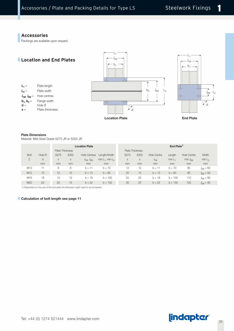
AccessoriesPackings are available upon request.
Calculation of bolt length see page 11
Plate DimensionsMaterial: Mild Steel Grade S275 JR or S355 JR
Location Plate End Plate1)
Plate Thickness Plate ThicknessBolt Hole Ø S275 S355 Hole Centres Length/Width S275 S355 Hole Centre Length Hole Centre Width
Z d s s l1M, l2M min L1, min L2 s s l1M min L1 min l2M min L2
mm mm mm mm mm mm mm mm mm mm mmM10 11 8 8 b + 11 b + 70 12 12 b + 11 b + 70 80 l2M + 60
M12 13 12 10 b + 13 b + 80 20 15 b + 13 b + 80 80 l2M + 60
M16 18 15 12 b + 18 b + 100 25 20 b + 18 b + 100 110 l2M + 80
M20 22 20 15 b + 22 b + 130 30 25 b + 22 b + 130 120 l2M + 90
1) Dependant on the use of the end plate the thickness might need to be increased.
Location and End Plates
L1 = Plate length
L2 = Plate width
l1M, l2M = Hole centres
b1, b2 = Flange widthd = Hole Øs = Plate thickness
L1
l1M
b1
L1
l1M
b1
L2 L2l2M l2M
b2
d
d
Location Plate End Plate

Min. Safe Working Load1)
Product Bolt 8.8 (5:1 Factor of Safety) DimensionsCode Z Tensile / 1 Bolt Torque Tail Length V X L H Width W
kN Nm mm mm mm mm mmRCS12 M12 2.6 69 10 6.5 - 26.5 76 29 50
RCS16 M16 4.0 147 10 9 - 24 76 29 50
RCS20 M20 9.6 285 10 11 - 22 76 29 50
RCS24 M24 12.3 491 10 13 - 20 76 29 50
1) The safe working load depends on the position of the bolt hole. The greater dimension X the lower the load.
Order example: RCS12 HDG with dimension X = ______ mm
26Tel: +44 (0) 1274 521444 www.lindapter.com
Steelwork FixingsType BR / Type RC 1
Type BRMalleable iron, bright zinc plated / hot dip galvanised
Type RCForged steel, corrosion protection as required
Safe Working Loads DimensionsProduct Bolt 8.8 (5:1 Factor of Safety) Tail Length VCode Z Tensile / 1 Bolt Frictional / 2 Bolts Torque Y X short medium T Width
kN kN Nm mm mm mm mm mm mmBR12 12 5.8 0.7 69 26 13 4 6 13 29
BR16 16 7.3 1.5 147 30 16 6 8 16 35
BR20 20 14.7 3 285 36 19 7 10 19 42
BR24 24 19.7 4.5 491 48 25 9 12 25 54
Versatile clamp for steel beams or rails. The skirt prevents the clamprotating during installation. The BR tail spans slotted holes.Suitable for flanges up to 8°.
Nose
Tail
W
X
Skirt
Hole to suitM12-M24
Flat Top
Tail
ClampingArea K
Nose
Skirt
T
V
X
Z
Y
Special clamp to secure railsor steel beams of 10mm orgreater. Packings are availablefor thicker flanges. The RC tailspans slotted holes.Suitable for flanges up to 5°.The product will be drilled tosuit hole size and positionrequirements of theapplications.
HV
Order example: BR12 short HDG
L
27Tel: +44 (0) 1274 521444 www.lindapter.com
Steelwork FixingsAccessories / Plate and Packing Details for Type BR 1
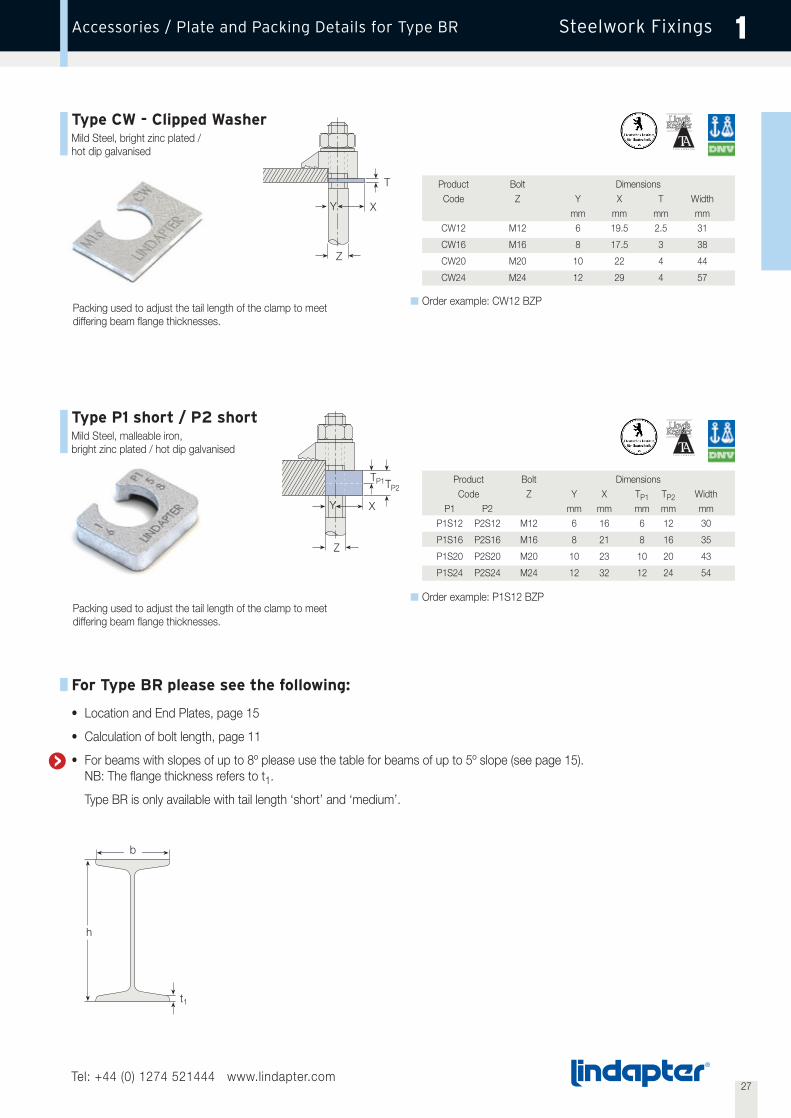
For Type BR please see the following:
• Location and End Plates, page 15
• Calculation of bolt length, page 11
• For beams with slopes of up to 8º please use the table for beams of up to 5º slope (see page 15).NB: The flange thickness refers to t1.
Type BR is only available with tail length ‘short’ and ‘medium’.
Type CW - Clipped WasherMild Steel, bright zinc plated /hot dip galvanised
Packing used to adjust the tail length of the clamp to meetdiffering beam flange thicknesses.
Packing used to adjust the tail length of the clamp to meetdiffering beam flange thicknesses.
Order example: CW12 BZP
Order example: P1S12 BZP
Product Bolt DimensionsCode Z Y X TP1 TP2 Width
P1 P2 mm mm mm mm mmP1S12 P2S12 M12 6 16 6 12 30
P1S16 P2S16 M16 8 21 8 16 35
P1S20 P2S20 M20 10 23 10 20 43
P1S24 P2S24 M24 12 32 12 24 54
Product Bolt DimensionsCode Z Y X T Width
mm mm mm mmCW12 M12 6 19.5 2.5 31
CW16 M16 8 17.5 3 38
CW20 M20 10 22 4 44
CW24 M24 12 29 4 57
b
h
t1
T
Z
TP1TP2
Z
Y X
XY
Type P1 short / P2 shortMild Steel, malleable iron,bright zinc plated / hot dip galvanised
1
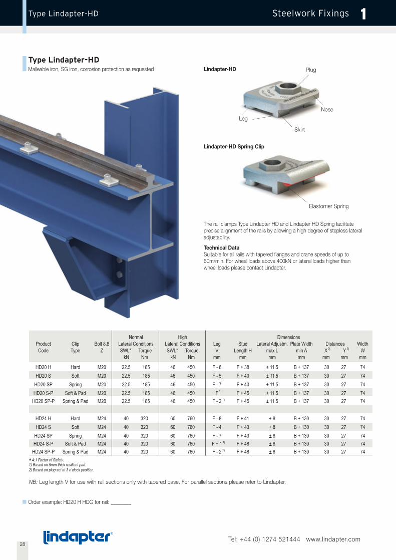
Malleable iron, SG iron, corrosion protection as requested
Skirt
Leg
Elastomer Spring
Nose
Plug
The rail clamps Type Lindapter HD and Lindapter HD Spring facilitateprecise alignment of the rails by allowing a high degree of stepless lateraladjustability.
Technical DataSuitable for all rails with tapered flanges and crane speeds of up to60m/min. For wheel loads above 400kN or lateral loads higher thanwheel loads please contact Lindapter.
Lindapter-HD
Lindapter-HD Spring Clip
28Tel: +44 (0) 1274 521444 www.lindapter.com
NB: Leg length V for use with rail sections only with tapered base. For parallel sections please refer to Lindapter.
Order example: HD20 H HDG for rail: ________
4:1 Factor of Safety.*
ProductCode
HD20 HHD20 S
HD20 SPHD20 S-P
HD20 SP-P
HD24 HHD24 S
HD24 SPHD24 S-P
HD24 SP-P
ClipType
HardSoft
SpringSoft & Pad
Spring & Pad
HardSoft
SpringSoft & Pad
Spring & Pad
Bolt 8.8Z
M20M20M20M20M20
M24M24M24M24M24
LegV
mm
F - 8F - 5F - 7
FF - 2
F - 8F - 4F - 7F + 1F - 2
1)
1)
1)
1)
StudLength H
mm
F + 38F + 40F + 40F + 45F + 45
F + 41F + 43F + 43F + 48F + 48
Lateral Adjustm.max Lmm
+ 11.5+ 11.5+ 11.5+ 11.5+ 11.5
+ 8+ 8+ 8+ 8+ 8
Plate Widthmin Amm
B + 137B + 137B + 137B + 137B + 137
B + 130B + 130B + 130B + 130B + 130
DistancesX Y
mm mm
30 2730 2730 2730 2730 27
30 2730 2730 2730 2730 27
2) 2)Width
Wmm
7474747474
7474747474
NormalLateral ConditionsSWL* Torque
kN Nm
22.5 18522.5 18522.5 18522.5 18522.5 185
40 32040 32040 32040 32040 320
HighLateral ConditionsSWL* Torque
kN Nm
46 45046 45046 45046 45046 450
60 76060 76060 76060 76060 760
Dimensions
1) Based on 5mm thick resilient pad.2) Based on plug set at 3 o’clock position.
29Tel: +44 (0) 1274 521444 www.lindapter.com
1
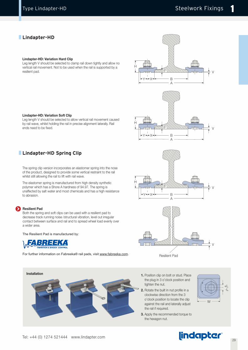
1. Position clip on bolt or stud. Placethe plug in 3 o’clock position andtighten the nut.
2. Rotate the built in nut profile in aclockwise direction from the 3o’clock position to locate the clipagainst the rail and laterally adjustthe rail if required.
3. Apply the recommended torque tothe hexagon nut.
W
Resilient Pad
Installation
Lindapter-HD: Variation Hard ClipLeg length V should be selected to clamp rail down tightly and allow novertical rail movement. Not to be used when the rail is supported by aresilient pad.
Y BA
H
V
Lindapter-HD: Variation Soft ClipLeg length V should be selected to allow vertical rail movement causedby rail wave, whilst holding the rail in precise alignment laterally. Railends need to be fixed.
The spring clip version incorporates an elastomer spring into the noseof the product, designed to provide some vertical restraint to the railwhilst still allowing the rail to lift with rail wave.
The elastomer spring is manufactured from high density syntheticpolymer which has a Shore A hardness of 94.97. The spring isunaffected by salt water and most chemicals and has a high resistanceto abrasion.
Resilient PadBoth the spring and soft clips can be used with a resilient pad todecrease track running noise /structural vibration, level out irregularcontact between surface and rail and to spread wheel load evenly overa wider area.
+L-L
X
F
F
F
Y BA
H
V
X
Y BA
H
V
V
X
Resilient PadBoth the spring and soft clips can be used with a resilient pad todecrease track running noise /structural vibration, level out irregularcontact between surface and rail and to spread wheel load evenly overa wider area.
The Resilient Pad is manufactured by:
For further information on Fabreeka® rail pads, visit www.fabreeka.com.
30Tel: +44 (0) 1274 521444 www.lindapter.com
Steelwork FixingsType BSNT / Type BSLN 1
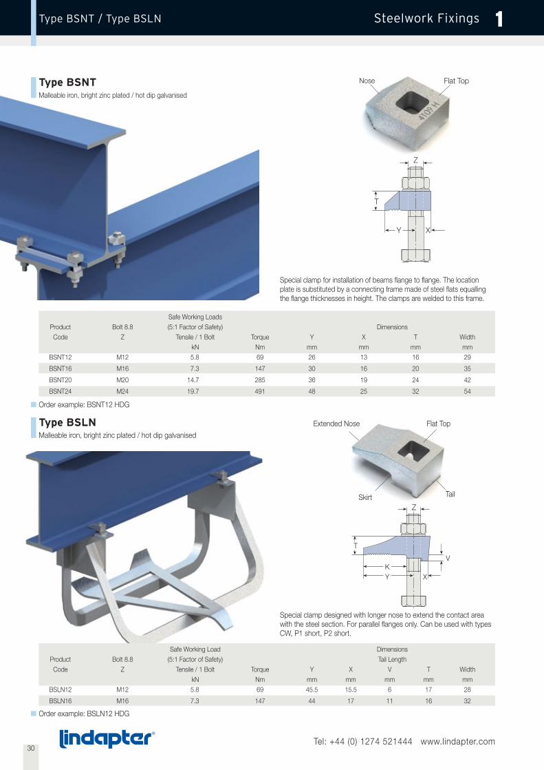
Type BSNTMalleable iron, bright zinc plated / hot dip galvanised
Nose Flat Top
T
Y X
Z
Safe Working LoadsProduct Bolt 8.8 (5:1 Factor of Safety) DimensionsCode Z Tensile / 1 Bolt Torque Y X T Width
kN Nm mm mm mm mmBSNT12 M12 5.8 69 26 13 16 29
BSNT16 M16 7.3 147 30 16 20 35
BSNT20 M20 14.7 285 36 19 24 42
BSNT24 M24 19.7 491 48 25 32 54
Safe Working Load DimensionsProduct Bolt 8.8 (5:1 Factor of Safety) Tail LengthCode Z Tensile / 1 Bolt Torque Y X V T Width
kN Nm mm mm mm mm mmBSLN12 M12 5.8 69 45.5 15.5 6 17 28
BSLN16 M16 7.3 147 44 17 11 16 32
Special clamp for installation of beams flange to flange. The locationplate is substituted by a connecting frame made of steel flats equallingthe flange thicknesses in height. The clamps are welded to this frame.
Type BSLNMalleable iron, bright zinc plated / hot dip galvanised
Special clamp designed with longer nose to extend the contact areawith the steel section. For parallel flanges only. Can be used with typesCW, P1 short, P2 short.
Extended Nose Flat Top
TailSkirt
Order example: BSLN12 HDG
Order example: BSNT12 HDG
T
YK
X
Z
V
31Tel: +44 (0) 1274 521444 www.lindapter.com
Steelwork FixingsType F9 / Type HW/HC 1
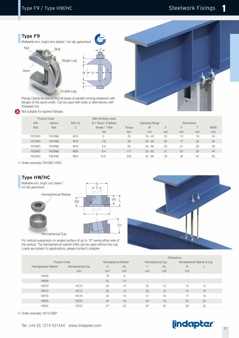
Type F9Malleable iron, bright zinc plated / hot dip galvanised
Type HW/HCMalleable iron, bright zinc plated /hot dip galvanised
Jaws
Nut
Double Leg
Bolt
Single Leg
W
V
V
Z
XT
Flange Clamp for connecting all types of parallel running steelwork withflanges of the same width. Can be used with bolts or alternatively withthreaded rod.
Not suitable for tapered flanges.
Product Code Safe Working Loadswith without Bolt 4.6 (5:1 Factor of Safety) Clamping Range DimensionsBolt Bolt Z Tensile / 1 Bolt Torque W X V T Width
kN Nm mm mm mm mm mmF910NC F910NB M10 2 20 19 - 42 25 13 19 24
F912NC F912NB M12 2.8 39 26 - 60 35 17 24 30
F916NC F916NB M16 5.6 93 29 - 69 43 21 28 35
F920NC F920NB M20 8.4 177 32 - 82 51 25 35 44
F924NC F924NB M24 14.0 235 45 - 95 76 38 55 63
DimensionsProduct Code Hemispherical Washer Hemispherical Cup Hemispherical Washer & Cup
Hemispherical Washer Hemispherical Cup X W1 Y W2 R Lmm mm mm mm mm mm
HW06 - 19 9 - - - -
HW08 - 22 10 - - - -
HW10 HC10 25 12 32 12 13 14
HW12 HC12 29 12 35 12 14 16
HW16 HC16 34 16 41 16 17 19
HW20 HC20 44 19 54 19 22 24
HW24 HC24 57 25 67 25 29 32
For vertical suspension on angled surface of up to 10° swing either side ofthe vertical. The hemispherical washer (HW) can be used without the cup.Loads are subject to applications, please contact Lindapter.
Order example: F910NC HDG
Order example: HC10 BZP
X
Y
10°
R
Z
L
Hemispherical Washer
Hemispherical Cup
W2W1

32Tel: +44 (0) 1274 521444 www.lindapter.com
Steelwork FixingsType SC / Type LP 1
Type SC / Type LPCorrosion Protection as required
Type SC
Type LP4
Type LP6
Bespoke units for multiple applications with vertical load, loads at an angle and rotation of up to 360°. Shown are typical applications, other loads anddesigns available. All loads subject to suitability of supporting section.
Type SCShackle Clamp with 4 BoltsLoading: up to 60.0kNDirections: vertical liftAngle: ± 10º
Type LP4Lifting Point with 4 BoltsLoading: up to 7t (68kN)Directions: 360º rotationAngle: 0 - 90º
Type LP6Lifting Point with 6 BoltsLoading: up to 10t (98kN)Directions: 360º rotationAngle: 0 - 90º
Order details: Loading, rotation, angle and beam dimensions
33Tel: +44 (0) 1274 521444 www.lindapter.com
Steelwork FixingsType FC 1
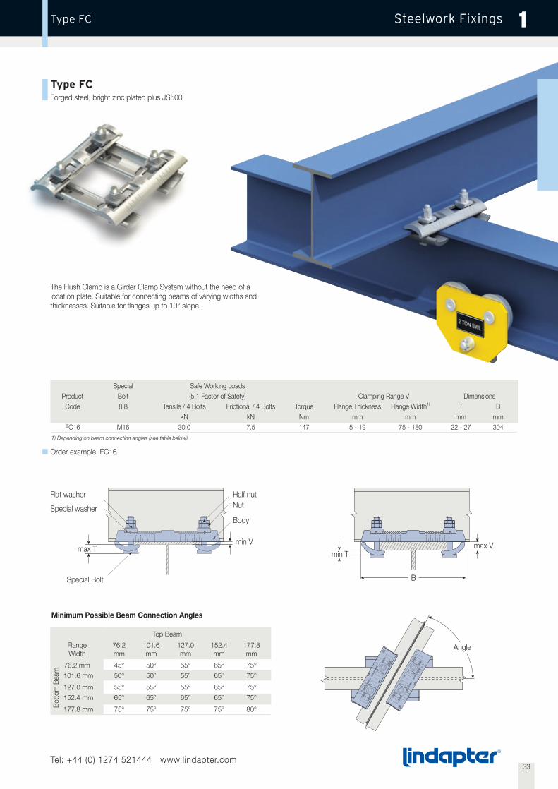
Type FCForged steel, bright zinc plated plus JS500
The Flush Clamp is a Girder Clamp System without the need of alocation plate. Suitable for connecting beams of varying widths andthicknesses. Suitable for flanges up to 10° slope.
Special Safe Working LoadsProduct Bolt (5:1 Factor of Safety) Clamping Range V DimensionsCode 8.8 Tensile / 4 Bolts Frictional / 4 Bolts Torque Flange Thickness Flange Width1) T B
kN kN Nm mm mm mm mmFC16 M16 30.0 7.5 147 5 - 19 75 - 180 22 - 27 304
1) Depending on beam connection angles (see table below).
Top Beam
Flange 76.2 101.6 127.0 152.4 177.8Width mm mm mm mm mm
76.2 mm 45° 50° 55° 65° 75°101.6 mm 50° 50° 55° 65° 75°
127.0 mm 55° 55° 55° 65° 75°152.4 mm 65° 65° 65° 65° 75°
177.8 mm 75° 75° 75° 75° 80°
Minimum Possible Beam Connection Angles
Flat washer
B
Special washer
max Tmin T
Angle
Nut
Body
Half nut
Special Bolt
Bot
tom
Bea
m
Order example: FC16
min V max V
34Tel: +44 (0) 1274 521444 www.lindapter.com
Steelwork FixingsLoads and Specifications 1
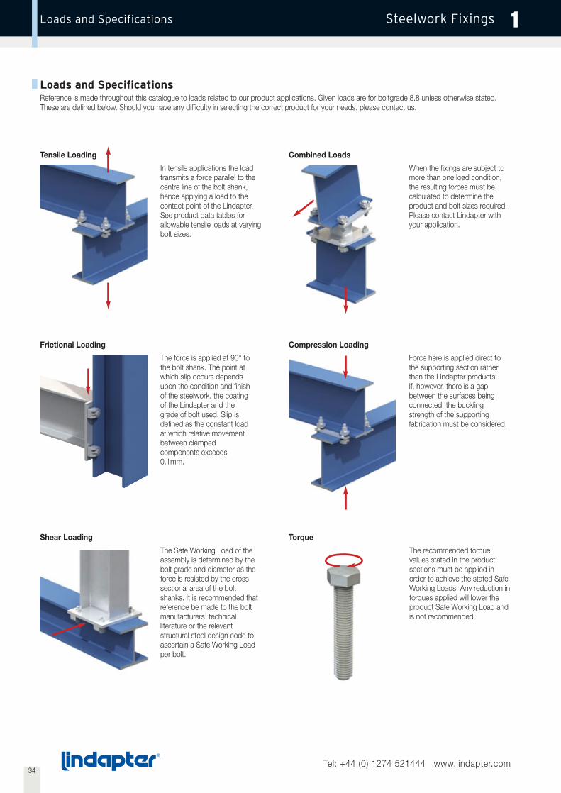
Loads and SpecificationsReference is made throughout this catalogue to loads related to our product applications. Given loads are for boltgrade 8.8 unless otherwise stated.These are defined below. Should you have any difficulty in selecting the correct product for your needs, please contact us.
In tensile applications the loadtransmits a force parallel to thecentre line of the bolt shank,hence applying a load to thecontact point of the Lindapter.See product data tables forallowable tensile loads at varyingbolt sizes.
Tensile Loading
The Safe Working Load of theassembly is determined by thebolt grade and diameter as theforce is resisted by the crosssectional area of the boltshanks. It is recommended thatreference be made to the boltmanufacturers’ technicalliterature or the relevantstructural steel design code toascertain a Safe Working Loadper bolt.
Shear Loading
The force is applied at 90° tothe bolt shank. The point atwhich slip occurs dependsupon the condition and finishof the steelwork, the coatingof the Lindapter and thegrade of bolt used. Slip isdefined as the constant loadat which relative movementbetween clampedcomponents exceeds0.1mm.
Frictional Loading
When the fixings are subject tomore than one load condition,the resulting forces must becalculated to determine theproduct and bolt sizes required.Please contact Lindapter withyour application.
Combined Loads
Force here is applied direct tothe supporting section ratherthan the Lindapter products.If, however, there is a gapbetween the surfaces beingconnected, the bucklingstrength of the supportingfabrication must be considered.
Compression Loading
The recommended torquevalues stated in the productsections must be applied inorder to achieve the stated SafeWorking Loads. Any reduction intorques applied will lower theproduct Safe Working Load andis not recommended.
Torque

35Tel: +44 (0) 1274 521444 www.lindapter.com
Steelwork FixingsTechnical Enquiry Fax 1
Technical Enquiry Fax
Fax: +44 (0) 1274 521130Email: [email protected]
Your details will only be used internally and not disclosed to third parties.
Date . . . . . . . . . . . . . . . . . . . . . . . . . . . . . . . . . . . . . . . . . . . . . . . .
Company . . . . . . . . . . . . . . . . . . . . . . . . . . . . . . . . . . . . . . . . . . . . . . . . . . . . . . . . . . . . . . . . . . . . . . . . . . . . . . . . . . . . . . . . . . . . . . . . . . . . . . .
Full Name . . . . . . . . . . . . . . . . . . . . . . . . . . . . . . . . . . . . . . . . . . . . . . . . . . . . . . . . . . . . . . . . . . . . . . . . . . . . . . . . . . . . . . . . . . . . . . . . . . . . . . .
Position . . . . . . . . . . . . . . . . . . . . . . . . . . . . . . . . . . . . . . . . . . . . . . . . . . Department . . . . . . . . . . . . . . . . . . . . . . . . . . . . . . . . . . . . . . . . . .
Address . . . . . . . . . . . . . . . . . . . . . . . . . . . . . . . . . . . . . . . . . . . . . . . . . . . . . . . . . . . . . . . . . . . . . . . . . . . . . . . . . . . . . . . . . . . . . . . . . . . . . . . .
Town . . . . . . . . . . . . . . . . . . . . . . . . . . . . . . . . . . . . . . . . . . . . . . . . . . . . Post Code . . . . . . . . . . . . . . . . . . . . . . . . . . . . . . . . . . . . . . . . . . .
Tel . . . . . . . . . . . . . . . . . . . . . . . . . . . . . . . . . . . . . . . . . . . . . . . . . . . . . . Fax . . . . . . . . . . . . . . . . . . . . . . . . . . . . . . . . . . . . . . . . . . . . . . . . .
E-mail . . . . . . . . . . . . . . . . . . . . . . . . . . . . . . . . . . . . . . . . . . . . . . . . . . . . Web www . . . . . . . . . . . . . . . . . . . . . . . . . . . . . . . . . . . . . . . . .
Project Name / Reference:
. . . . . . . . . . . . . . . . . . . . . . . . . . . . . . . . . . . . . . . . . . . . . . . . . . . . . . . . . . . . . . . . . . . . . . . . . . . . . . . . . . . . . . . . . . . . . . . . . . . . . . . . . . . . . . .
. . . . . . . . . . . . . . . . . . . . . . . . . . . . . . . . . . . . . . . . . . . . . . . . . . . . . . . . . . . . . . . . . . . . . . . . . . . . . . . . . . . . . . . . . . . . . . . . . . . . . . . . . . . . . . .
1. Is your case comparable with an application in this catalogue? If yes, please state page and number . . . . . . . . . . . . . . . . . . . . . . .
If no, please enclose drawing detail ❍
2. Load per connection:
Tensile . . . . . . . . . . . . . . . kN
Frictional . . . . . . . . . . . . . kN
Please state any special load conditions (vibration, etc.) . . . . . . . . . . . . . . . . . . . . . . . . . . . . . . . . . . . . . . . . . . . . . . . . . . . . . . . . . . . . . . . . .
Static Load ❍
Dynamic Load ❍ Load Cycles . . . . . . . . . . . . . . .
3. Beam Type Flange Width Flange Thickness
Top Beam
Bottom Beam
4. Corrosion protection of beams . . . . . . . . . . . . . . . . . . . . . . . . . . . . . . . . . . . . . . . . . . . . . . . . . . . . . . . . . . . . . . . . . . . . . . . . . . . . . . . . . . . .
5. Number of connections required. . . . . . . . . . . . . . . . . . . . . . . . . . . . . . . . . . . . . . . . . . . . . . . . . . . . . . . . . . . . . . . . . . . . . . . . . . . . . . . . . . .

36Tel: +44 (0) 1274 521444 www.lindapter.com
Steelwork FixingsTypical Applications 1
1 2 3
4 5 6
7 8 9

37Tel: +44 (0) 1274 521444 www.lindapter.com
Steelwork FixingsTypical Applications 1
5
10
13
11 12
14 15
16 17 18

38Tel: +44 (0) 1274 521444 www.lindapter.com
Steelwork FixingsTypical Applications 1
19 20 21
22 23 24
25 26 27

39Tel: +44 (0) 1274 521444 www.lindapter.com
Steelwork FixingsTypical Applications 1
34
28
31
29 30
32 33
35 36
40
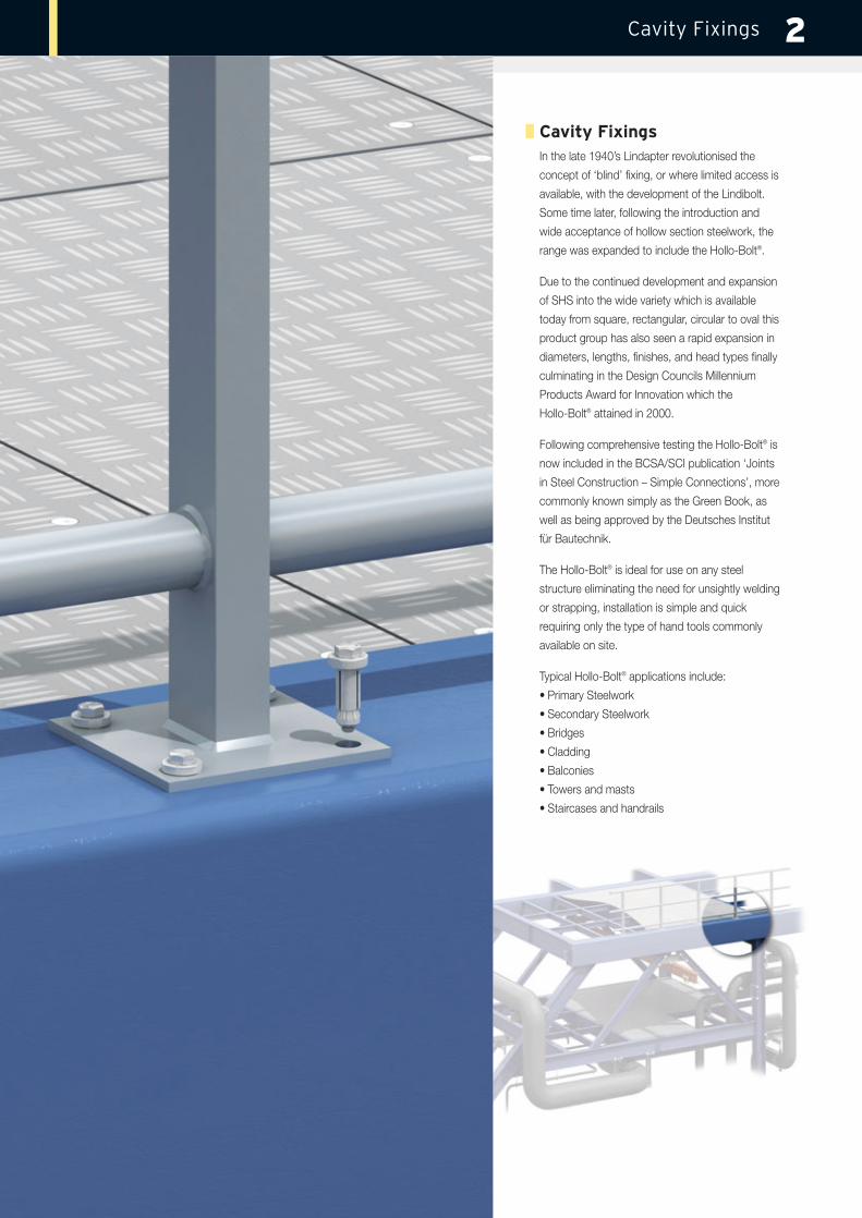
Cavity FixingsIn the late 1940’s Lindapter revolutionised the
concept of ‘blind’ fixing, or where limited access is
available, with the development of the Lindibolt.
Some time later, following the introduction and
wide acceptance of hollow section steelwork, the
range was expanded to include the Hollo-Bolt®.
Due to the continued development and expansion
of SHS into the wide variety which is available
today from square, rectangular, circular to oval this
product group has also seen a rapid expansion in
diameters, lengths, finishes, and head types finally
culminating in the Design Councils Millennium
Products Award for Innovation which the
Hollo-Bolt® attained in 2000.
Following comprehensive testing the Hollo-Bolt® is
now included in the BCSA/SCI publication ‘Joints
in Steel Construction – Simple Connections’, more
commonly known simply as the Green Book, as
well as being approved by the Deutsches Institut
für Bautechnik.
The Hollo-Bolt® is ideal for use on any steel
structure eliminating the need for unsightly welding
or strapping, installation is simple and quick
requiring only the type of hand tools commonly
available on site.
Typical Hollo-Bolt® applications include:
• Primary Steelwork
• Secondary Steelwork
• Bridges
• Cladding
• Balconies
• Towers and masts
• Staircases and handrails
Cavity Fixings 2
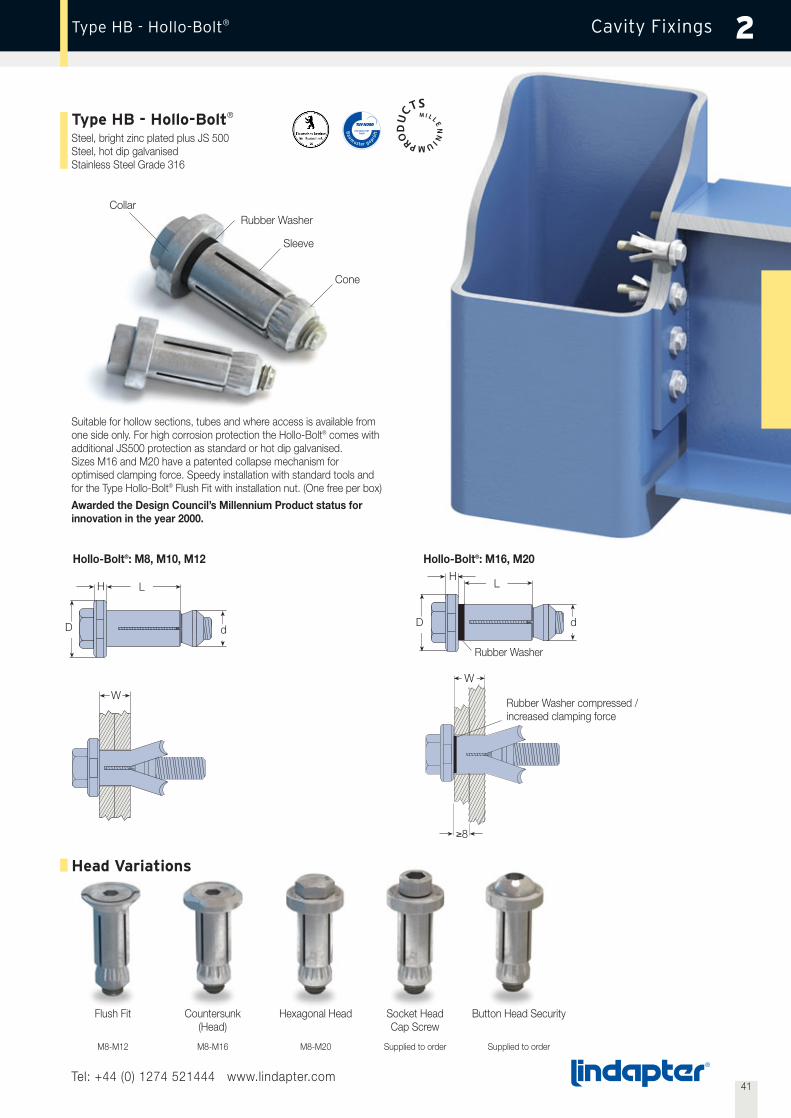
Flush Fit Countersunk(Head)
Hexagonal Head Socket HeadCap Screw
Button Head Security
M8-M12 M8-M16 M8-M20 Supplied to order Supplied to order
41Tel: +44 (0) 1274 521444 www.lindapter.com
Cavity Fixings 2
Type HB - Hollo-Bolt®
Steel, bright zinc plated plus JS 500Steel, hot dip galvanisedStainless Steel Grade 316
Head Variations
Suitable for hollow sections, tubes and where access is available fromone side only. For high corrosion protection the Hollo-Bolt® comes withadditional JS500 protection as standard or hot dip galvanised.Sizes M16 and M20 have a patented collapse mechanism foroptimised clamping force. Speedy installation with standard tools andfor the Type Hollo-Bolt® Flush Fit with installation nut. (One free per box)
Awarded the Design Council’s Millennium Product status forinnovation in the year 2000.
W
Hollo-Bolt®: M8, M10, M12
Type HB - Hollo-Bolt®
Collar
H L
dD
W
Hollo-Bolt®: M16, M20H
Rubber Washer
L
dD
8
Rubber Washer compressed /increased clamping force
Rubber Washer
Sleeve
Cone

42Tel: +44 (0) 1274 521444 www.lindapter.com
Cavity FixingsLoad Tables for Types HB and HBFF 2
Type HB - Hollo-Bolt®
Product Bolt Clamping Outer Sleeve Collar Torque SHS Section Safe Working Loads2)
Code Thickness Ply1) (5:1 Factor of Safety)Length Outer Ø Height Ø A/F Tensile Single
Material Dimensions ShearW min t L d H D
mm mm mm mm mm mm mm Nm mm kN kNHB08-1 M8x50 3 - 22 - 30 140x140x5.0 4.0HB08-2 M8x70 22 - 41 - 49 13.75 5 22 19 23 S275 150x150x6.3 4.0 5.0HB08-3 M8x90 41 - 60 - 68 200x200x10.0 4.0
100x100x6.3 7.0HB10-1 M10x55 3 - 22 - 30 140x140x5.0 6.0HB10-2 M10x75 22 - 41 - 48 17.75 6 29 24 45 S275 140x140x8.0 8.5 10.0HB10-3 M10x90 41 - 60 - 67 150x150x6.3 8.0
180x180x8.0 7.0200x200x10.0 8.0140x140x5.0 6.5
HB12-1 M12x60 3 - 25 - 35 140x140x8.0 10.5HB12-2 M12x90 25 - 47 - 57 19.75 7 32 30 80 S275 150x150x6.3 10.0 15.0HB12-3 M12x110 47 - 69 - 79 180x180x8.0 10.0
200x200x10.0 10.5100x100x6.3 13.5100x100x10.0 18.5140x140x5.0 8.0
HB16-1 M16x75 12 - 29 8 41.5 140x140x6.3 15.0HB16-2 M16x100 29 - 50 8 63 25.75 8 38 36 190 S275 140x140x8.0 20.0 30.0HB16-3 M16x120 50 - 71 8 84 140x140x12.5 21.0
150x150x6.3 11.5180x180x8.0 17.0200x200x10.0 15.0140x140x6.3 16.0140x140x8.0 23.0
HB20-1 M20x90 12 - 34 8 50 140x140x10.0 25.0HB20-2 M20x120 34 - 60 8 76 32.75 10 51 46 300 S275 140x140x12.5 35.0 40.0HB20-3 M20x150 60 - 86 8 102 150x150x6.3 12.5
180x180x8.0 18.0200x200x10.0 19.0
Order example: HB08-1 BZP plus JS 500HBFF08-1 BZP plus JS 500 without / with ____ installation nut(s)
Type HBFF - Hollo-Bolt® Flush Fit Product Counter Clamping Outer Sleeve Collar Installation Torque SHS Section Safe Working Loads
Code Sunk Thickness Ply Tool (5:1 Factor of Safety)Bolt Length Outer Ø Height Ø A/F Material Dimensions Tensile Single
ShearW min t L d H D
mm mm mm mm mm mm mm mm Nm mm kN kN140x140x5.0 4.0
HBFF08-1 M8x50 5 10 - 27 8 30 13.75 5 24 19 23 S275 150x150x6.3 4.0 5.0180x180x8.0 4.0200x200x10.0 4.0100x100x6.3 7.0140x140x5.0 6.0
HBFF10-1 M10x60 6 12 - 27 10 30 17.75 6 30 24 45 S275 140x140x8.0 8.5 10.0150x150x6.3 8.0180x180x8.0 7.0200x200x10.0 8.0140x140x5.0 6.5140x140x8.0 10.5
HBFF12-1 M12x60 8 12 - 30 10 35 19.75 7 33 30 80 S275 150x150x6.3 10.0 15.0180x180x8.0 10.0200x200x10.0 10.5
1) The thickness of the outer ply needs to be at least 8mm. If necessary spacer washers should be used beneath the collar toincrease the thickness to 8mm.
2) The Hollo-Bolt® can be used on a wide variety of SHS sections; those shown above are only representative to give anindication of variations in Hollo-Bolt® capacity.The safe working loads, in both tension and shear, are applicable to the Hollo-Bolt® only, failure of the section, particularlyon those with thin walls and a wide chord face, could occur at a lower figure and its strength should be checked using the‘Green Book’ design guide.
1. Align pre-drilled fixture andsteelwork. Insert Hollo-Bolt®
through fixture and steelwork.
2. Apply installation nut and grip nutwith an open ended spanner.
3. Using a torque wrench, tighten thecentral counter-sunk bolt to therecommended torque.
43Tel: +44 (0) 1274 521444 www.lindapter.com
Cavity FixingsTechnical Data for Types HB and HBFF 2
Joints in Steel Construction - Simple Connections
A
min t
90º
Installation nut
B C
d1
d2
d1
Installation Hollo-Bolt®
Installation Hollo-Bolt® Flush Fit
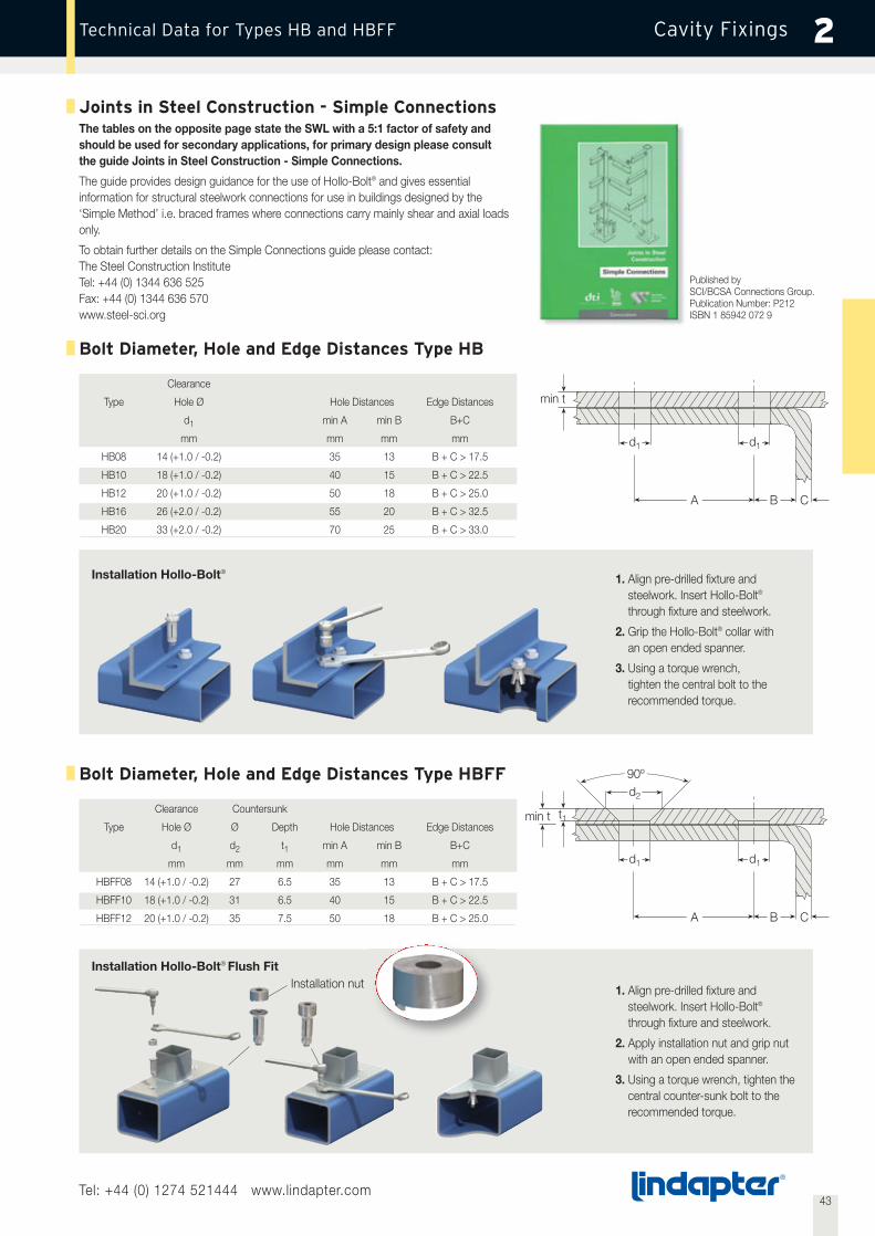
Bolt Diameter, Hole and Edge Distances Type HB
1. Align pre-drilled fixture andsteelwork. Insert Hollo-Bolt®
through fixture and steelwork.
2. Grip the Hollo-Bolt® collar withan open ended spanner.
3. Using a torque wrench,tighten the central bolt to therecommended torque.
Clearance
Type Hole Ø Hole Distances Edge Distances
d1 min A min B B+C
mm mm mm mm
HB08 14 (+1.0 / -0.2) 35 13 B + C > 17.5
HB10 18 (+1.0 / -0.2) 40 15 B + C > 22.5
HB12 20 (+1.0 / -0.2) 50 18 B + C > 25.0
HB16 26 (+2.0 / -0.2) 55 20 B + C > 32.5
HB20 33 (+2.0 / -0.2) 70 25 B + C > 33.0
t1
A B C
d1 d1
min t
Bolt Diameter, Hole and Edge Distances Type HBFF
Clearance Countersunk
Type Hole Ø Ø Depth Hole Distances Edge Distances
d1 d2 t1 min A min B B+C
mm mm mm mm mm mm
HBFF08 14 (+1.0 / -0.2) 27 6.5 35 13 B + C > 17.5
HBFF10 18 (+1.0 / -0.2) 31 6.5 40 15 B + C > 22.5
HBFF12 20 (+1.0 / -0.2) 35 7.5 50 18 B + C > 25.0
The tables on the opposite page state the SWL with a 5:1 factor of safety andshould be used for secondary applications, for primary design please consultthe guide Joints in Steel Construction - Simple Connections.
The guide provides design guidance for the use of Hollo-Bolt® and gives essentialinformation for structural steelwork connections for use in buildings designed by the‘Simple Method’ i.e. braced frames where connections carry mainly shear and axial loadsonly.
To obtain further details on the Simple Connections guide please contact:The Steel Construction InstituteTel: +44 (0) 1344 636 525Fax: +44 (0) 1344 636 570www.steel-sci.org
Published bySCI/BCSA Connections Group.Publication Number: P212ISBN 1 85942 072 9

44Tel: +44 (0) 1274 521444 www.lindapter.com
Cavity FixingsType LB2 - Lindibolt 2® 2
Type LB2 - Lindibolt 2®
Steel, Stainless Steel Grade 316, bright zinc plated
Locknut
Setscrew
Main Body
Nut
Cone
W
F
D C
B A
d Z
PY
Self heading bolt suitable for fixing to hollow-sections, tubes and whereaccess is available from one side only. The Lindibolt® uses a standardclearance hole.
1. Set nut (C) at (W) plus projection (P).Tighten Locknut (D).
2. Align pre-drilled fixtures. Insert Lindibolt® through both fixtures,cone end first.
3. Hold nut (C) with spanner and tighten bolt (F).Loosen off locknut (D) and tighten nut (C).Secure by re-tightening locknut (D).
Installation
Safe Working Load1) TorqueProduct Lindibolt® Hole (Factor of Safety 5:1) Clamping Length Projection Main Body B and Nut C&D Setscrew FCode Size Length Ø Tensile Single Thread Bolt
Z Y d Shear W P Z Torque A/F F Torque A/Fmm mm kN kN mm mm Nm mm Nm mm
LB10 M10 69 11 3.0 3.4 7 - 30 7.5 - 10 M10 20 17 M5 6 8
LB12 M12 80 13 5.0 5.0 10 - 36 9 - 12 M12 31 19 M6 11 10
LB16 M16 105 17 8.0 9.8 12 - 48 12 - 16 M16 81 24 M8 23 13
LB20 M20 128 21 14.0 15.2 14 - 60 15 - 20 M20 129 30 M10 45 17
LB24 M24 158 25 20.0 22.5 18 - 72 18 - 24 M24 203 36 M12 80 19
1) The safe working loads, in both tension and shear, shown above are applicable to the Lindibolt 2® only.Failure of the section, particularly on those with thin walls and a wide chord face, could occur at a lower figure and its strength should be checked.
Order example: LB10 BZP
W
Washer

45Tel: +44 (0) 1274 521444 www.lindapter.com
Cavity FixingsTypical Applications 2
1
3
5
2
4
6

46
Composite Decking Fixings 3
Composite Decking FixingsLindapter composite decking fixings have all been
designed in conjunction with the various decking
manufacturers to ensure they fulfil the necessary
requirements from ease of installation to carrying
capacity. All the fixings are designed to fit inside
the dovetail shaped re-entrant channel which is
common throughout all the profiles and give a
secure point from which building services can be
suspended with guaranteed capacities.
To guarantee the published capacities it is
important that all the Lindapter Composite Decking
Fixings are installed only when the slab has been
poured and the concrete reaches full strength.
Advantages include:
• Speed of installation
• No special tools required
• No weakening of the decking profiles
• No damage of the surfaces of the decking
• No possibility of delamination
• Adjustable and easily removable
Tel: +44 (0) 1274 521444 www.lindapter.com

Composite Decking Fixings
Type MFBracket: Steel strip, electro zinc plate (yellow iridescent) trivalent passivate plus JS 500Met-Nut: Malleable iron, bright zinc plated
1. Pre-assemble the Met-Nut and bracket onto the threaded rod and insert one side of the bracket into the decking.2. Insert the other side of the bracket to position inside the decking.3.4. Tighten the nut on the rod to a torque of 10Nm / 7ft lbs (prevent rod from rotating).
If in doubt, please contact Lindapter’s Technical Support Department for advice.
Installation
Met-Nut
Bracket
ProductCode
MF06MF08MF10
Rod
M6M8
M10
Safe Working Load(3:1 Factor of Safety)
Tensile / 1 rod kN
TorqueNm
101010
1. 2. 3. 4.
manufactured by Composite Metal Flooring (CMF®).
manufactured by Kingspan Structural Products.
The application example above shows the Lindapter Type MF with an M8 Stud End Fixing (HF-DMFG-NO2-1M) manufactured by
The table opposite details safe working loads of the Lindapter Type MF installed with threaded rod, for load capabilities of the Gripple End Fixing, please visit www.gripple.com.
®
3Type MF
Tel: +44 (0) 1274 521444 www.lindapter.com

47Tel: +44 (0) 1274 521444 www.lindapter.com
Composite Decking FixingsType AW 3
Locking Plate
Wedge
Installation
1. Pre-assemble the Alphawedge and Locking Plate onto the threaded rod (flat surface uppermost).
2. Insert wedge into the re-entrant channel of the decking, rotate 90°.
3. Slide plate up the threaded rod, over the wedge, to lock it in position into the channel.
4. Tighten the locknut beneath the plate to hold the assembly in position.
1. 2. 3. 4.
The Alphawedge is designed for Ribdeck AL, E60 and 80 profilesmanufactured by Richard Lees Steel Decking (see page 52).
Safe Working LoadProduct Rod (3:1 Factor of Safety)Code 4.6 Tensile / 1 Rod Torque
kN NmAW06 M6 1.0 10
AW08 M8 1.0 10
AW10 M10 1.0 10
Type AW - AlphawedgeLocking Plate: Pre-galvanised stripWedge: Malleable iron, bright zinc plated
Order example: AW06
48Tel: +44 (0) 1274 521444 www.lindapter.com
Composite Decking FixingsType MW2 3
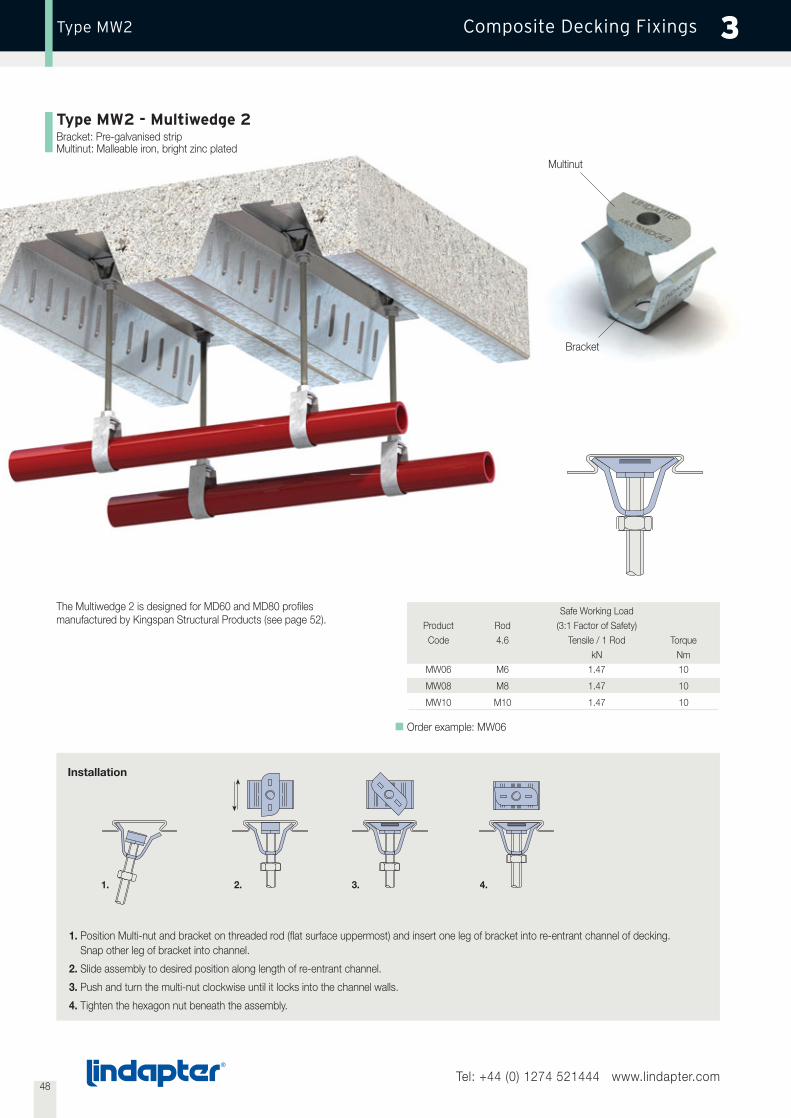
Type MW2 - Multiwedge 2Bracket: Pre-galvanised stripMultinut: Malleable iron, bright zinc plated
Bracket
Multinut
The Multiwedge 2 is designed for MD60 and MD80 profilesmanufactured by Kingspan Structural Products (see page 52).
Order example: MW06
Safe Working LoadProduct Rod (3:1 Factor of Safety)Code 4.6 Tensile / 1 Rod Torque
kN NmMW06 M6 1.47 10
MW08 M8 1.47 10
MW10 M10 1.47 10
Installation
1. Position Multi-nut and bracket on threaded rod (flat surface uppermost) and insert one leg of bracket into re-entrant channel of decking.Snap other leg of bracket into channel.
2. Slide assembly to desired position along length of re-entrant channel.
3. Push and turn the multi-nut clockwise until it locks into the channel walls.
4. Tighten the hexagon nut beneath the assembly.
1. 2. 3. 4.
49Tel: +44 (0) 1274 521444 www.lindapter.com
Composite Decking FixingsType TR60 / Type VN 3
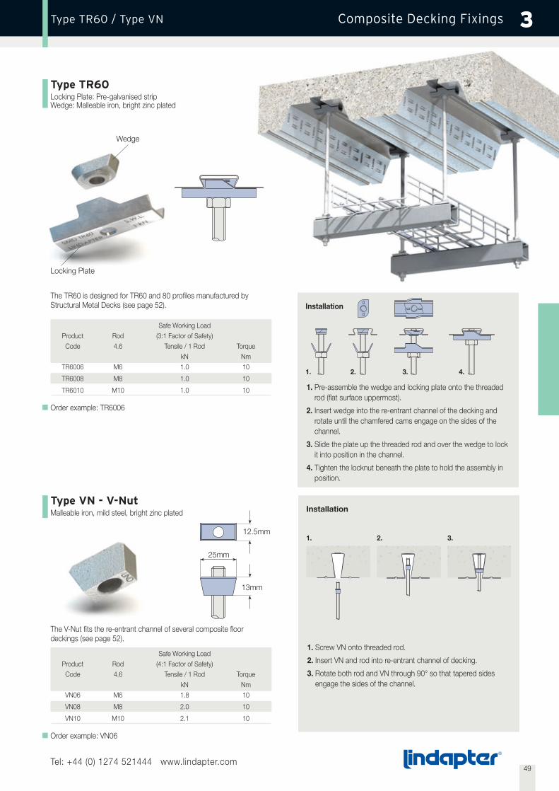
Type VN - V-NutMalleable iron, mild steel, bright zinc plated
Type TR60Locking Plate: Pre-galvanised stripWedge: Malleable iron, bright zinc plated
The TR60 is designed for TR60 and 80 profiles manufactured byStructural Metal Decks (see page 52).
The V-Nut fits the re-entrant channel of several composite floordeckings (see page 52).
Order example: TR6006
Safe Working LoadProduct Rod (3:1 Factor of Safety)Code 4.6 Tensile / 1 Rod Torque
kN NmTR6006 M6 1.0 10
TR6008 M8 1.0 10
TR6010 M10 1.0 10
Order example: VN06
Safe Working LoadProduct Rod (4:1 Factor of Safety)Code 4.6 Tensile / 1 Rod Torque
kN NmVN06 M6 1.8 10
VN08 M8 2.0 10
VN10 M10 2.1 10
1. Pre-assemble the wedge and locking plate onto the threadedrod (flat surface uppermost).
2. Insert wedge into the re-entrant channel of the decking androtate until the chamfered cams engage on the sides of thechannel.
3. Slide the plate up the threaded rod and over the wedge to lockit into position in the channel.
4. Tighten the locknut beneath the plate to hold the assembly inposition.
Installation
1. Screw VN onto threaded rod.
2. Insert VN and rod into re-entrant channel of decking.
3. Rotate both rod and VN through 90° so that tapered sidesengage the sides of the channel.
1. 2. 3.
Locking Plate
Wedge
13mm
25mm
12.5mm
Installation
1. 2. 3. 4.

50Tel: +44 (0) 1274 521444 www.lindapter.com
Composite Decking FixingsType SD2 3
Type SD2 - Slimdek 2Pre-galvanised strip
Main Body
Inner Body
The Slimdek 2 is designed for the CF225 profile manufactured byCorus Panels and Profiles. It gives a fully flexible suspension position(see page 52).
Order example: SD206
Safe Working LoadProduct Rod (3:1 Factor of Safety)Code 4.6 Tensile / 1 Rod Torque
kN NmSD206 M6 1.0 12
SD208 M8 1.0 12
SD210 M10 1.0 12
Installation
1. 2. 3.
4. 5. 6.
1. With Slimdek 2 in it’s retracted position (as supplied) locate the fixing in the re-entrant channel.
2. Hold Slimdek 2 in position with one hand, then rotate cam into the direction shown above with a spanner.
3. Rotate the nut until the inner body of the fixing locates against the re-entrant channel, and the nut feels tight.
4. Offer the V-Nut on a threaded rod up to the main body.
5. Rotate V-Nut through 90° to allow it to sit at the bottom of the Slimdek 2 body.
6. Secure the assembly with a nut.
Cam
V-Nut

51Tel: +44 (0) 1274 521444 www.lindapter.com
Composite Decking FixingsType TC 3
Type TC - Toggle ClampSteel Strip, bright zinc plated
The Toggle Clamp is designed for service suspension from pre-casthollow core slabs (minimum depth of core 75mm) as well as SHS,steel sheeting or purlins.
Safe Working LoadProduct Rod Hole (4:1 Factor of Safety) DimensionsCode min. 8.8 Ø Tensile / 1 Rod Torque T W Width V
mm kN Nm mm mm mmTC08 M8 22 2.45 10 68 16.5 13
TC10 M10 25 2.45 10 68 17.5 15
Order example: TC08
V
W
T
LINDAPTER
LINDAPTER
LINDAPTER
LINDAPTERLINDAPTER
LINDAPTER
1. 2. 3. 4. 5. 6.
Installation
1. Drill hole. If toggle is to be used to support from pre-cast hollow core slab, ensure hole is central to hollow core.
2. Insert threaded rod through toggle, ensuring nut is flush with end of rod.
3. Align toggle parallel with rod, so that nut engages into the retaining cavity.
4. Offer up the assembly, inserting the toggle body completely through the hole.
5. Shake rod so that toggle body locates horizontally across hole.Allow rod to drop down so that the nut locates in the seat in the toggle body.
6. Wind up rod to top of section as shown as high as possible. Secure the assembly with a nut and washer.
Nut
Toggle

Decking Profiles Lindapter Decking Fixings
Kingspan Structural Products
Corus Panels & Profiles
Richard Lees Steel Decking
Structural Metal Decks
Type MW2
Type SD2
Type AW
Type TR60
Type VN
• MD60• MD80
• CF225
• Ribdeck AL• Ribdeck E60 • Ribdeck 80
• TR60• TR80
Structural Metal Decks• R51
Corus Panel & Profiles• CF51
Richard Lees Steel Decking• Holorib
Kingspan Structural Products• MD50
Composite Metal Flooring (CMF)• Metfloor 55
Composite Metal Flooring (CMF)
• Metfloor 60• Metfloor 80
Type MF
3
52Tel: +44 (0) 1274 521444 www.lindapter.com
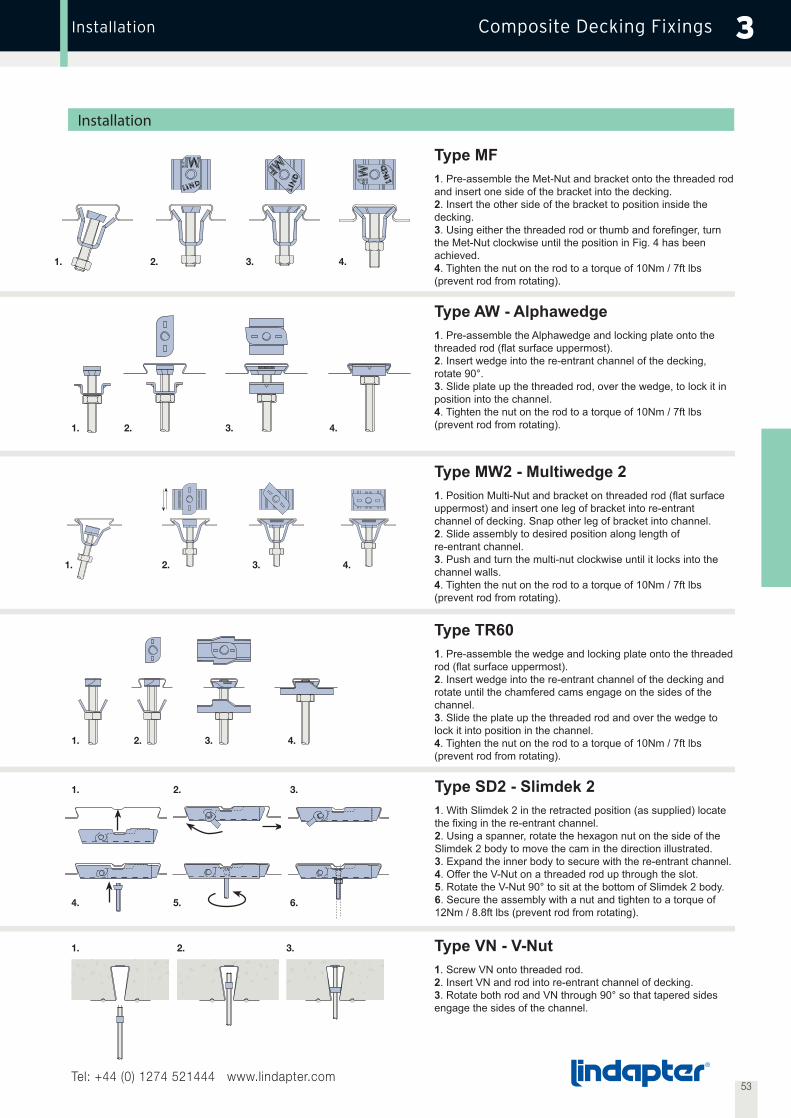
3
53Tel: +44 (0) 1274 521444 www.lindapter.com
Installation
1. 2. 3. 4.
1. 2. 3. 4.
1. 2. 3. 4.
1. 2. 3.
4. 5. 6.
1. 2. 3.
Type MF1. Pre-assemble the Met-Nut and bracket onto the threaded rod and insert one side of the bracket into the decking.2. Insert the other side of the bracket to position inside the decking.3the Met-Nut clockwise until the position in Fig. 4 has been achieved.4. Tighten the nut on the rod to a torque of 10Nm / 7ft lbs (prevent rod from rotating).
Type AW - Alphawedge1. Pre-assemble the Alphawedge and locking plate onto the
2rotate 90°.3position into the channel.4. Tighten the nut on the rod to a torque of 10Nm / 7ft lbs (prevent rod from rotating).
Type MW2 - Multiwedge 21uppermost) and insert one leg of bracket into re-entrantchannel of decking. Snap other leg of bracket into channel.2. Slide assembly to desired position along length ofre-entrant channel.3. Push and turn the multi-nut clockwise until it locks into the channel walls.4. Tighten the nut on the rod to a torque of 10Nm / 7ft lbs (prevent rod from rotating).
Type TR601. Pre-assemble the wedge and locking plate onto the threaded
2. Insert wedge into the re-entrant channel of the decking and rotate until the chamfered cams engage on the sides of the channel.3. Slide the plate up the threaded rod and over the wedge to lock it into position in the channel.4. Tighten the nut on the rod to a torque of 10Nm / 7ft lbs (prevent rod from rotating).
Type VN - V-Nut1. Screw VN onto threaded rod.2. Insert VN and rod into re-entrant channel of decking.3. Rotate both rod and VN through 90° so that tapered sidesengage the sides of the channel.
1. 2. 3. 4.
Type SD2 - Slimdek 21. With Slimdek 2 in the retracted position (as supplied) locate
2Slimdek 2 body to move the cam in the direction illustrated.34. Offer the V-Nut on a threaded rod up through the slot.5. Rotate the V-Nut 90° to sit at the bottom of Slimdek 2 body.6. Secure the assembly with a nut and tighten to a torque of 12Nm / 8.8ft lbs (prevent rod from rotating).

54
Support Fixings 4
Support FixingsLindapter’s support fixing range offers a series of ideal solutions for all
building services. This includes the suspension of HVAC equipment,
pipe work, fire protection/sprinkler systems, suspended ceilings and all
manner of electrical equipment such as cable tray and ladder. These
products have all been designed to give speed and ease of installation
to reduce time and keep costs under control.
Where necessary support products have been tested, and approved,
by the relevant bodies such as those which oversee and insure fire
protection installations.
For the installation of heavy duty service equipment such as pipe
supports used in the petro chemical industry the steelwork fixings in
section 1 of this catalogue are more suitable.
Tel: +44 (0) 1274 521444 www.lindapter.com

Locknut
Setscrew Z
Nut BasketSwivel Unit
55Tel: +44 (0) 1274 521444 www.lindapter.com
Support FixingsType FLS 4
Type FLSHigh Grade Alloy Steel, bright zinc plated
U
Y
W X
R
Beam flange clamp with swivel unit. For parallel and sloping flanges.Supplied with grade 8.8 setscrew for secure grip.
Safe Working Load (4:1 Factor of Safety) TorqueProduct Thread Tensile/ 25º Tensile/> 25º to 45° Clamping Thickness Setscrew Setscrew Nut DimensionsCode Y W Z Z N R T U X Width
kN kN mm Nm Nm mm mm mm mm mmFLS08 M8 2.5 1.5 3 - 17 M10 18 18 55 53 58 27 28
FLS10 M10 2.5 1.5 3 - 17 M10 18 18 55 53 58 27 28
Order example: FLS08
1. 2. 3. 4.
Z
MN
S
Installation Approved Applications
General ApplicationsParallel Flanges only1. Locate FLS onto flange.
2. Ensuring lug on locknut locates into main body, tighten downsetscrew (Z), and then tighten upper locknut (N).
3. Install threaded rod by screwing into nut located in nut basket (S).Ensure full thread capture.
4. Secure assembly in nut basket (S) from beneath using a locknut(not supplied).
Ensure that the cup point setscrew always grips on thetapered side of the flange.
25°
45° 45°
25° 25°
90°
T
360º
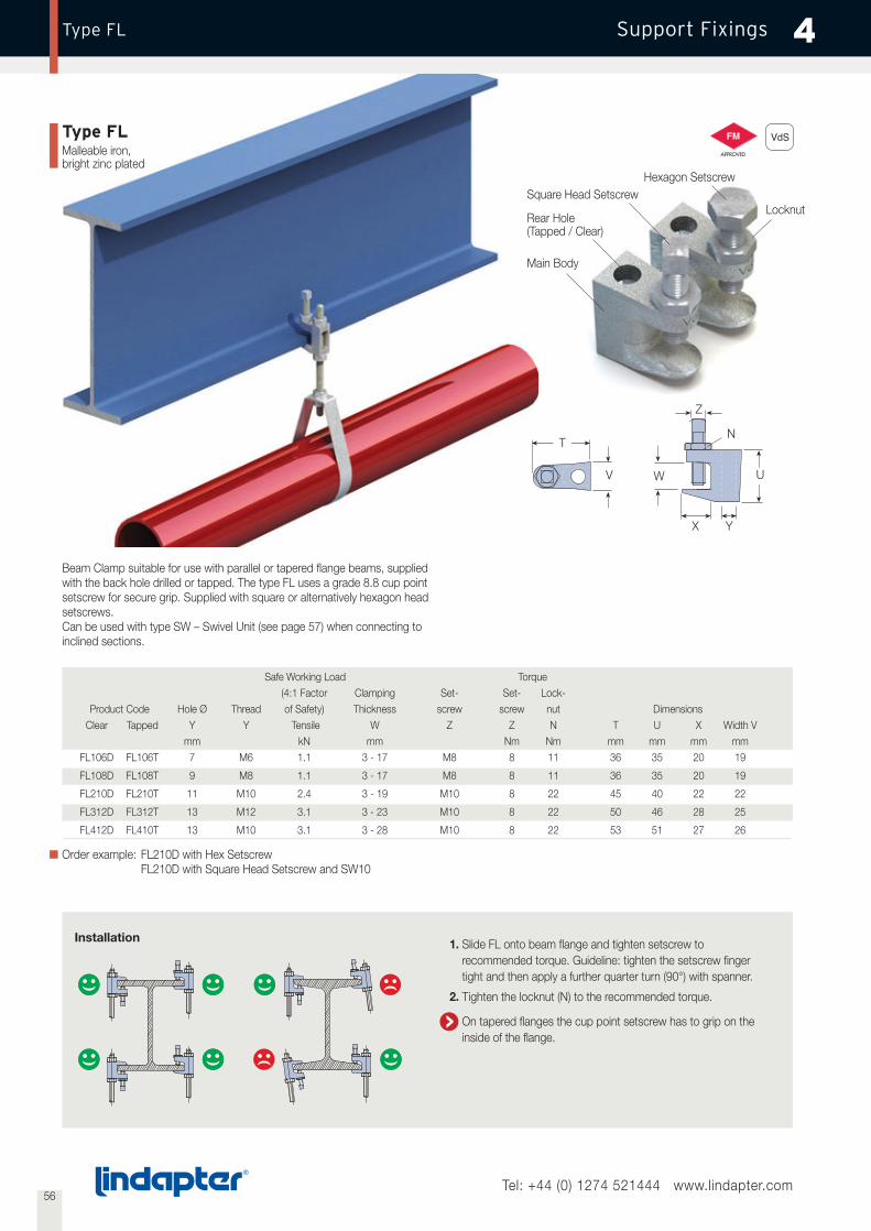
56Tel: +44 (0) 1274 521444 www.lindapter.com
Support FixingsType FL 4
Locknut
Hexagon Setscrew
Rear Hole(Tapped / Clear)
Main Body
T
V
X Y
U
Z
W
Beam Clamp suitable for use with parallel or tapered flange beams, suppliedwith the back hole drilled or tapped. The type FL uses a grade 8.8 cup pointsetscrew for secure grip. Supplied with square or alternatively hexagon headsetscrews.Can be used with type SW – Swivel Unit (see page 57) when connecting toinclined sections.
Safe Working Load Torque(4:1 Factor Clamping Set- Set- Lock-
Product Code Hole Ø Thread of Safety) Thickness screw screw nut DimensionsClear Tapped Y Y Tensile W Z Z N T U X Width V
mm kN mm Nm Nm mm mm mm mmFL106D FL106T 7 M6 1.1 3 - 17 M8 8 11 36 35 20 19
FL108D FL108T 9 M8 1.1 3 - 17 M8 8 11 36 35 20 19
FL210D FL210T 11 M10 2.4 3 - 19 M10 8 22 45 40 22 22
FL312D FL312T 13 M12 3.1 3 - 23 M10 8 22 50 46 28 25
FL412D FL410T 13 M10 3.1 3 - 28 M10 8 22 53 51 27 26
Order example: FL210D with Hex SetscrewFL210D with Square Head Setscrew and SW10
Installation 1. Slide FL onto beam flange and tighten setscrew torecommended torque. Guideline: tighten the setscrew fingertight and then apply a further quarter turn (90°) with spanner.
2. Tighten the locknut (N) to the recommended torque.
On tapered flanges the cup point setscrew has to grip on the inside of the flange.
Type FLMalleable iron,bright zinc plated
N
Square Head Setscrew

57Tel: +44 (0) 1274 521444 www.lindapter.com
Support FixingsType LC / Type SW - Swivel Unit 4
Type SW - Swivel UnitHigh Grade Alloy Steel, bright zinc plated
Type LCMalleable iron, bright zinc plated
Swivel unit for applications on inclined beams. Can be used with type FL or type Z10.
Supplied complete with grade 8.8 M10 x 90 setscrew and nut.
Safe Working Load DimensionsProduct (4:1 Factor of Safety) Max. With BoltCode Rod Tensile Inclination Rotation Torque U R Width V
kN Nm mm mm mmSW10 M10 2.4 18° 360° 11 45 25 35
Order example: SW10
Setscrew
Locknut
Main Body
Beam clamp with tapped holes in position X and Y to accept threaded rod or cable clips.For parallel or tapered flanges. Supplied with grade 8.8 cup point setscrew.
Z
N
X U
Y
W
T
V
Safe Working Load TorqueProduct Thread (4:1 Factor of Safety) Clamping Thickness Setscrew Setscrew Locknut DimensionsCode X Y Tensile / in Pos. X Tensile / in Pos. Y W Z Z N T U Width V
kN kN mm Nm Nm mm mm mm
LC06 M6 M6 0.18 0.59 3 - 20 M6 4 4 25 36 21
LC08 M8 M8 0.18 0.59 3 - 20 M6 4 4 25 36 21
Order example: LC06
R
U
V
Installation see page 56 – type FL
Type FL
Type Z10
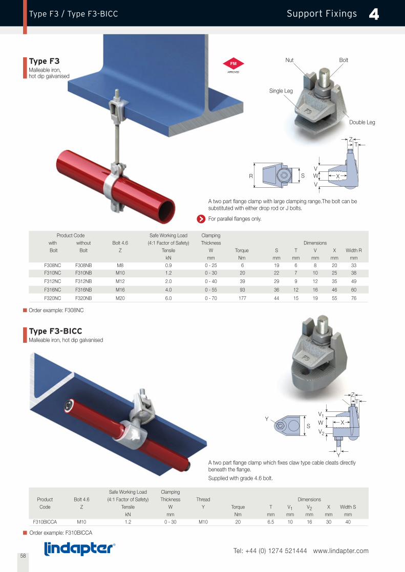
58Tel: +44 (0) 1274 521444 www.lindapter.com
Support Fixings 4Type F3 / Type F3-BICC
Type F3Malleable iron,hot dip galvanised
Product Code Safe Working Load Clampingwith without Bolt 4.6 (4:1 Factor of Safety) Thickness DimensionsBolt Bolt Z Tensile W Torque S T V X Width R
kN mm Nm mm mm mm mm mmF308NC F308NB M8 0.9 0 - 25 6 19 6 8 20 33F310NC F310NB M10 1.2 0 - 30 20 22 7 10 25 38
F312NC F312NB M12 2.0 0 - 40 39 29 9 12 35 49
F316NC F316NB M16 4.0 0 - 55 93 36 12 16 46 60
F320NC F320NB M20 6.0 0 - 70 177 44 15 19 55 76
A two part flange clamp with large clamping range.The bolt can besubstituted with either drop rod or J bolts.
For parallel flanges only.
A two part flange clamp which fixes claw type cable cleats directlybeneath the flange.
Supplied with grade 4.6 bolt.
Order example: F308NC
T
W X
V2
Y
Z
V1
R W XV
T
VS
Safe Working Load ClampingProduct Bolt 4.6 (4:1 Factor of Safety) Thickness Thread DimensionsCode Z Tensile W Y Torque T V1 V2 X Width S
kN mm Nm mm mm mm mm mmF310BICCA M10 1.2 0 - 30 M10 20 6.5 10 16 30 40
Order example: F310BICCA
YS
Single Leg
Double Leg
Nut Bolt
Z
Type F3-BICCMalleable iron, hot dip galvanised

59Tel: +44 (0) 1274 521444 www.lindapter.com
Support FixingsType SH / Type HW/HC 4
Type SHPre-galvanised strip
The strap hanger carries FM approval for use in fire sprinklerinstallations. Supplied with or without a hanger nut.
A
Y
BC
Product Codewith without Pipe Nuts Hole Ø DimensionsNut Nut Bore Tapped Y A B C
mm mm mm mmSH025N SH025 25 M8 or M10 11 22 75 58
SH032N SH032 32 M8 or M10 11 22 86 64
SH040N SH040 40 M8 or M10 11 22 99 74
SH050N SH050 50 M8 or M10 11 22 116 85
SH065N SH065 65 M8 or M10 11 22 135 97
Order example: SH025N with M10 hanger nut
Product Codewith without Pipe Nuts Hole Ø DimensionsNut Nut Bore Tapped Y A B C
mm mm mm mmSH080N SH080 80 M8 or M10 11 22 159 114
SH100N SH100 100 M8 or M10 11 22 219 161
SH125N SH125 125 M12 13 27 247 177
SH150N SH150 150 M12 13 27 284 200
SH200N SH200 200 M16 18 24 373 261
Hanger Nut
With special nut
With standard nut
Type HW/HCMalleable iron, bright zinc plated /hot dip galvanised
DimensionsProduct Code Hemispherical Washer Hemispherical Cup Hemispherical Washer & Cup
Hemispherical Washer Hemispherical Cup X W1 Y W2 R Lmm mm mm mm mm mm
HW06 - 19 9 - - - -
HW08 - 22 10 - - - -
HW10 HC10 25 12 32 12 13 14
HW12 HC12 29 12 35 12 14 16
HW16 HC16 34 16 41 16 17 19
HW20 HC20 44 19 54 19 22 24
HW24 HC24 57 25 67 25 29 32
For vertical suspension on angled surface of up to 10° swing either side ofthe vertical. The hemispherical washer (HW) can be used without the cup.Loads are subject to applications, please contact Lindapter.
Order example: HC10 BZP
X
Y
10°
R
Z
L
Hemispherical Washer
Hemispherical Cup
W2W1

60Tel: +44 (0) 1274 521444 www.lindapter.com
Support Fixings 4Type Z10 / Type HCW30
Type Z10Mild steel - bright zinc plated
Type HCW30Pre-galvanised strip
A purlin clip to suit a large range of purlin sections. Can be used withtype SW – Swivel Unit (see page 57) for use on inclined purlins.
Order example: Z10Z10 with SW10
Safe Working LoadProduct (3:1 Factor of Safety)Code Purlins Rod Tensile Torque
kN NmZ10 Kingspan M10 0.2 8
Multibeam 2 & 3
Z10 Metsec M10 0.1 - 0.2 8
Z10 Zeta M10 0.15 8
Order example: HCW30
Safe Working LoadProduct (3:1 Factor of Safety)Code Purlins Rod Tensile Torque
kN NmHCW30 Kingspan M10 0.2 8
Multibeam 3
2. 3.
Installation
1.
2.
Installation
1.
The purlin clip HCW30 is suitable for horizontal purlins. Can be usedwith type SW-Swivel Unit (see page 57) for use on inclined purlins.
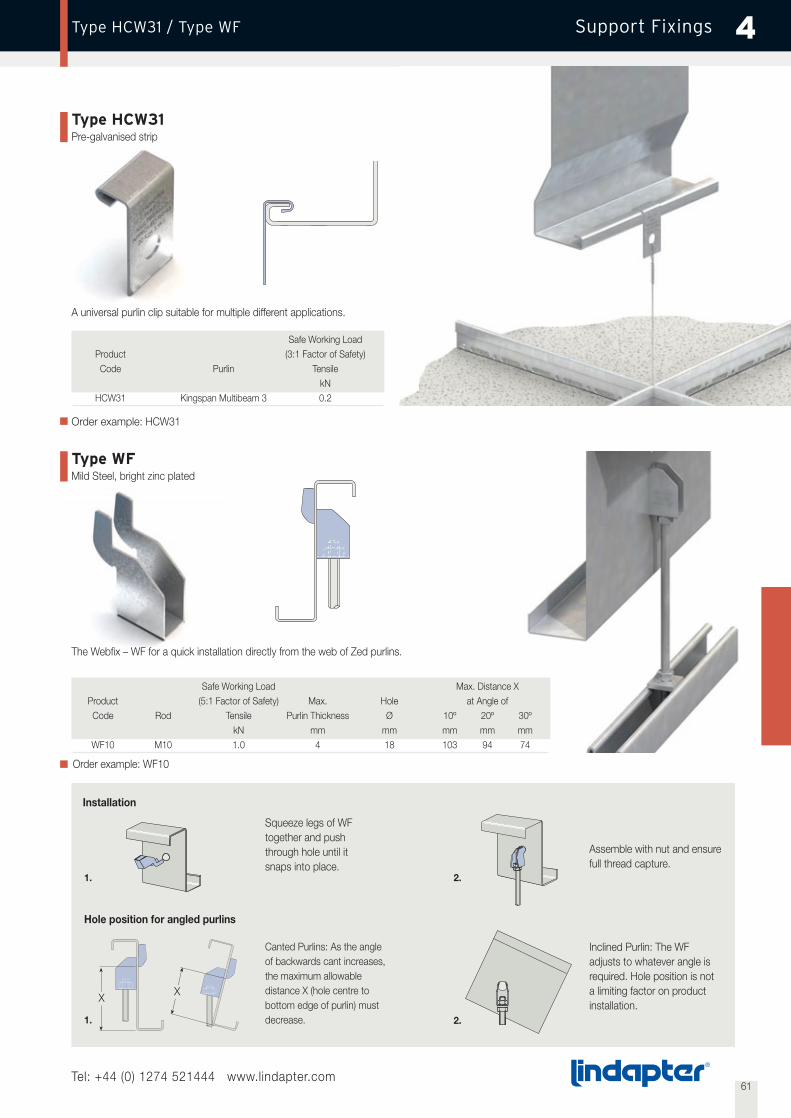
Installation
61Tel: +44 (0) 1274 521444 www.lindapter.com
Support FixingsType HCW31 / Type WF 4
Hole position for angled purlins
Inclined Purlin: The WFadjusts to whatever angle isrequired. Hole position is nota limiting factor on productinstallation.
Canted Purlins: As the angleof backwards cant increases,the maximum allowabledistance X (hole centre tobottom edge of purlin) mustdecrease.
Assemble with nut and ensurefull thread capture.
Squeeze legs of WFtogether and pushthrough hole until itsnaps into place.
X
1. 2.
1. 2.
Type HCW31Pre-galvanised strip
A universal purlin clip suitable for multiple different applications.
Order example: HCW31
Safe Working LoadProduct (3:1 Factor of Safety)Code Purlin Tensile
kNHCW31 Kingspan Multibeam 3 0.2
Safe Working Load Max. Distance XProduct (5:1 Factor of Safety) Max. Hole at Angle ofCode Rod Tensile Purlin Thickness Ø 10º 20º 30º
kN mm mm mm mm mmWF10 M10 1.0 4 18 103 94 74
Order example: WF10
Type WFMild Steel, bright zinc plated
The Webfix – WF for a quick installation directly from the web of Zed purlins.
X

62Tel: +44 (0) 1274 521444 www.lindapter.com
Support Fixings 4Type HCW34
Type HCW34Pre-galvanised strip
A one-piece wrap around purlinhanger. The HCW34 can be used tosuspend from canted purlins at upto 15° from the vertical.
PurlinKingspan Multibeam 3 Safe Working Load (3:1 Factor of Safety)
Product Code Purlin Height Total Height H Rod Tensilemm mm kN
HCW34/145 145 210 M10 0.75
HCW34/175 175 240 M10 0.75
HCW34/205 205 270 M10 0.75
HCW34/235 235 300 M10 0.75
HCW34/265 265 330 M10 0.75
Order example: HCW34/145
Purlin Profiles
MultichannelLipped C Section
Swagebeam Multibeam Zed Section
SFS C Section UltraBEAM Zeta Section Ultrazed Section
H
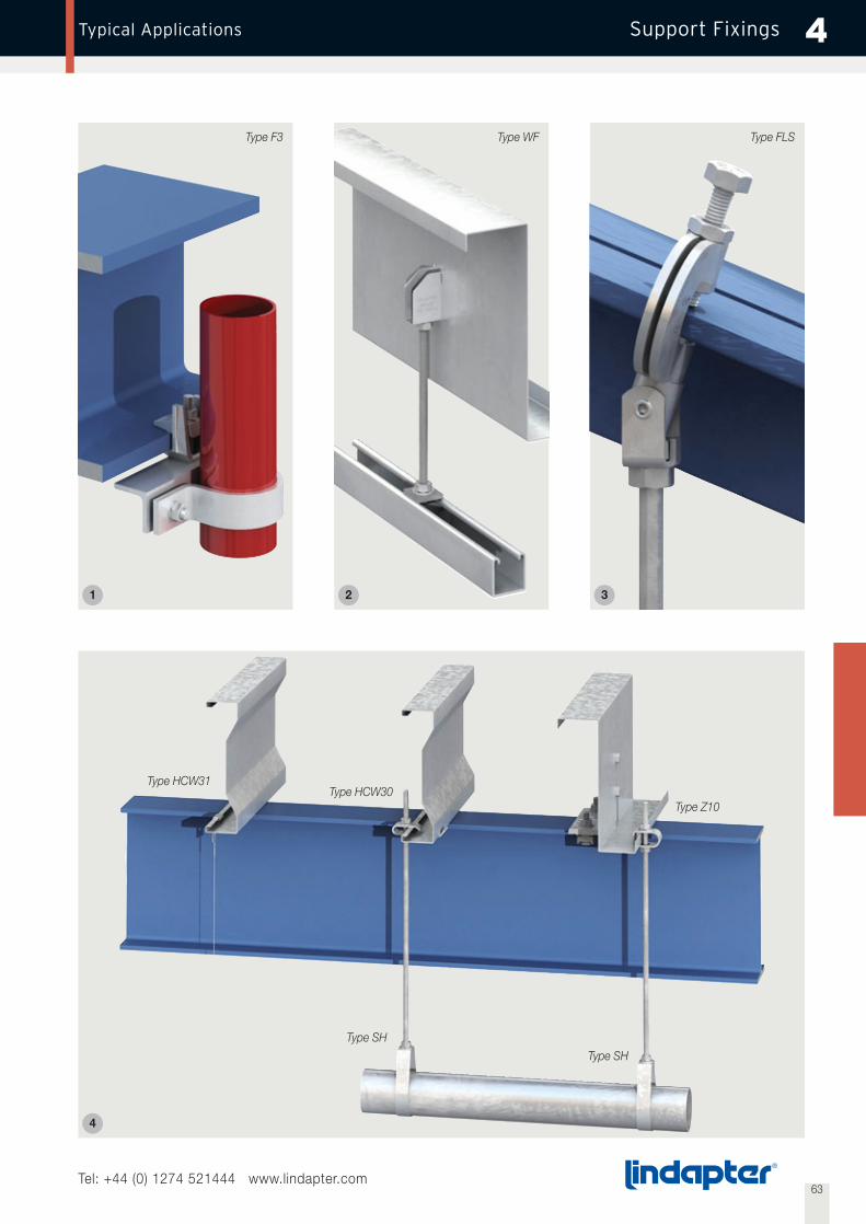
63Tel: +44 (0) 1274 521444 www.lindapter.com
Support FixingsTypical Applications 4
21 3
4
Type Z10Type HCW30
Type HCW31
Type SH
Type SH
Type WF Type FLSType F3
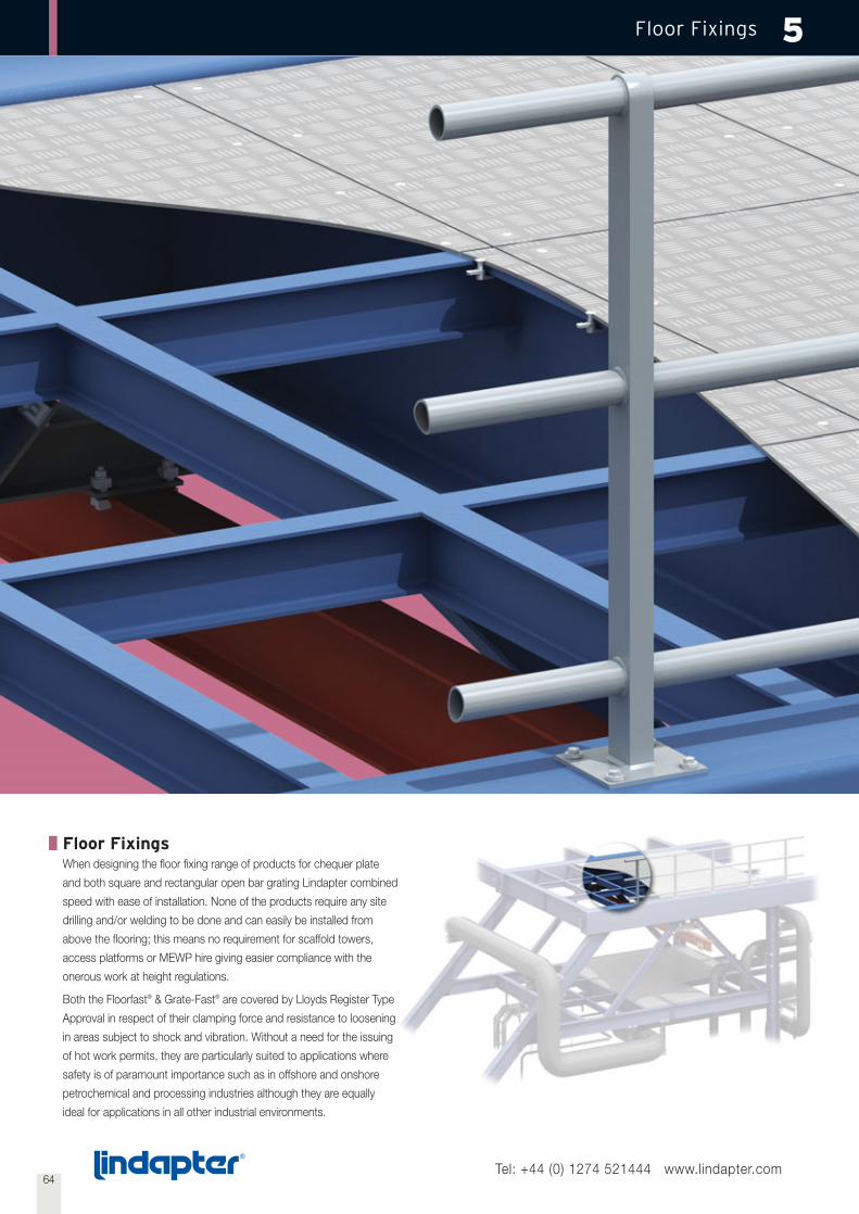
64
Floor Fixings 5
Floor FixingsWhen designing the floor fixing range of products for chequer plate
and both square and rectangular open bar grating Lindapter combined
speed with ease of installation. None of the products require any site
drilling and/or welding to be done and can easily be installed from
above the flooring; this means no requirement for scaffold towers,
access platforms or MEWP hire giving easier compliance with the
onerous work at height regulations.
Both the Floorfast® & Grate-Fast® are covered by Lloyds Register Type
Approval in respect of their clamping force and resistance to loosening
in areas subject to shock and vibration. Without a need for the issuing
of hot work permits, they are particularly suited to applications where
safety is of paramount importance such as in offshore and onshore
petrochemical and processing industries although they are equally
ideal for applications in all other industrial environments.
Tel: +44 (0) 1274 521444 www.lindapter.com
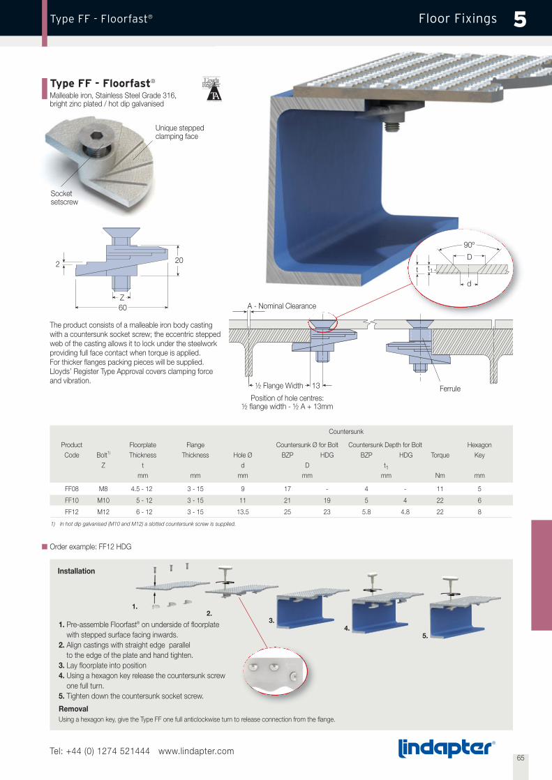
65
Floor FixingsType FF - Floorfast® 5
Type FF - Floorfast®
Malleable iron, Stainless Steel Grade 316,bright zinc plated / hot dip galvanised
The product consists of a malleable iron body castingwith a countersunk socket screw; the eccentric steppedweb of the casting allows it to lock under the steelworkproviding full face contact when torque is applied.For thicker flanges packing pieces will be supplied.Lloyds’ Register Type Approval covers clamping forceand vibration.
Countersunk
Product Floorplate Flange Countersunk Ø for Bolt Countersunk Depth for Bolt HexagonCode Bolt1) Thickness Thickness Hole Ø BZP HDG BZP HDG Torque Key
Z t d D t1mm mm mm mm mm Nm mm
FF08 M8 4.5 - 12 3 - 15 9 17 - 4 - 11 5
FF10 M10 5 - 12 3 - 15 11 21 19 5 4 22 6
FF12 M12 6 - 12 3 - 15 13.5 25 23 5.8 4.8 22 8
1) In hot dip galvanised (M10 and M12) a slotted countersunk screw is supplied.
Order example: FF12 HDG
1. Pre-assemble Floorfast® on underside of floorplatewith stepped surface facing inwards.
2. Align castings with straight edge parallelto the edge of the plate and hand tighten.
3. Lay floorplate into position4. Using a hexagon key release the countersunk screw
one full turn.5. Tighten down the countersunk socket screw.
RemovalUsing a hexagon key, give the Type FF one full anticlockwise turn to release connection from the flange.
Unique steppedclamping face
Socketsetscrew
2 20
60Z
1.
3.4.
5.
2.
Position of hole centres:½ flange width - ½ A + 13mm
½ Flange Width 13
A - Nominal Clearance
Ferrule
t
90º
d
Dt1
Installation
Tel: +44 (0) 1274 521444 www.lindapter.com
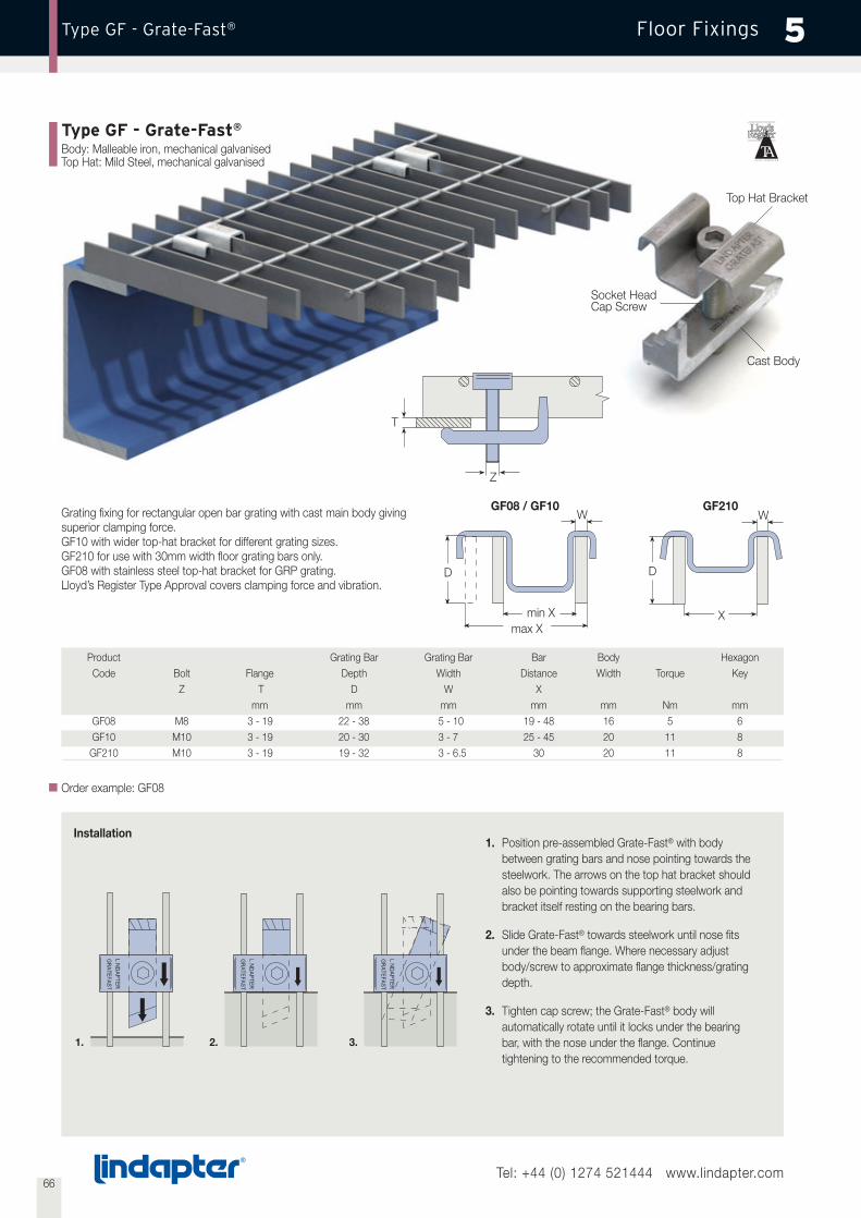
66Tel: +44 (0) 1274 521444 www.lindapter.com
Floor FixingsType GF - Grate-Fast® 5
Type GF - Grate-Fast®
Body: Malleable iron, mechanical galvanisedTop Hat: Mild Steel, mechanical galvanised
Installation1. Position pre-assembled Grate-Fast® with body
between grating bars and nose pointing towards thesteelwork. The arrows on the top hat bracket shouldalso be pointing towards supporting steelwork andbracket itself resting on the bearing bars.
2. Slide Grate-Fast® towards steelwork until nose fitsunder the beam flange. Where necessary adjustbody/screw to approximate flange thickness/gratingdepth.
3. Tighten cap screw; the Grate-Fast® body willautomatically rotate until it locks under the bearingbar, with the nose under the flange. Continuetightening to the recommended torque.
1. 2. 3.
Grating fixing for rectangular open bar grating with cast main body givingsuperior clamping force.GF10 with wider top-hat bracket for different grating sizes.GF210 for use with 30mm width floor grating bars only.GF08 with stainless steel top-hat bracket for GRP grating.Lloyd’s Register Type Approval covers clamping force and vibration.
Product Grating Bar Grating Bar Bar Body HexagonCode Bolt Flange Depth Width Distance Width Torque Key
Z T D W Xmm mm mm mm mm Nm mm
GF08 M8 3 - 19 22 - 38 5 - 10 19 - 48 16 5 6GF10 M10 3 - 19 20 - 30 3 - 7 25 - 45 20 11 8GF210 M10 3 - 19 19 - 32 3 - 6.5 30 20 11 8
Order example: GF08
W
DD
W
Xmax X
min X
GF210GF08 / GF10
Cast Body
Socket HeadCap Screw
Top Hat Bracket
Z
T
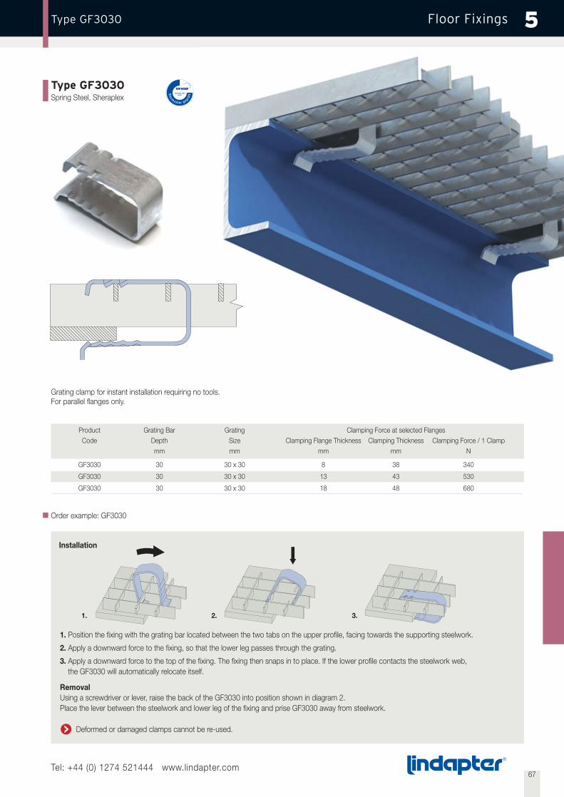
Installation
67Tel: +44 (0) 1274 521444 www.lindapter.com
Floor FixingsType GF3030 5
Type GF3030Spring Steel, Sheraplex
Grating clamp for instant installation requiring no tools.For parallel flanges only.
Order example: GF3030
Product Grating Bar Grating Clamping Force at selected FlangesCode Depth Size Clamping Flange Thickness Clamping Thickness Clamping Force / 1 Clamp
mm mm mm mm N
GF3030 30 30 x 30 8 38 340
GF3030 30 30 x 30 13 43 530
GF3030 30 30 x 30 18 48 680
1. Position the fixing with the grating bar located between the two tabs on the upper profile, facing towards the supporting steelwork.
2. Apply a downward force to the fixing, so that the lower leg passes through the grating.
3. Apply a downward force to the top of the fixing. The fixing then snaps in to place. If the lower profile contacts the steelwork web,the GF3030 will automatically relocate itself.
RemovalUsing a screwdriver or lever, raise the back of the GF3030 into position shown in diagram 2.Place the lever between the steelwork and lower leg of the fixing and prise GF3030 away from steelwork.
Deformed or damaged clamps cannot be re-used.
1. 2. 3.
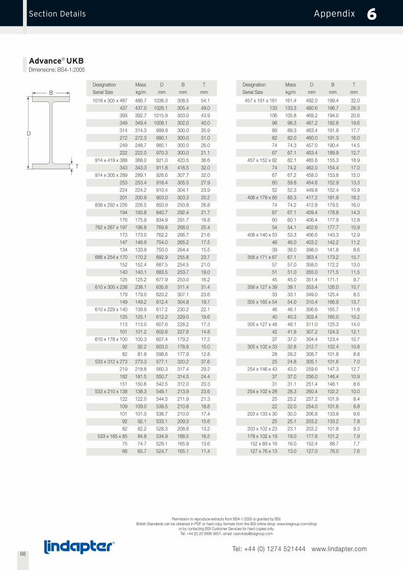
68Tel: +44 (0) 1274 521444 www.lindapter.com
AppendixSection Details 6
Advance® UKBDimensions: BS4-1:2005
B
D
T
Designation Mass D B TSerial Size kg/m mm mm mm
1016 x 305 x 487 486.7 1036.3 308.5 54.1437 437.0 1026.1 305.4 49.0393 392.7 1015.9 303.0 43.9349 349.4 1008.1 302.0 40.0314 314.3 999.9 300.0 35.9272 272.3 990.1 300.0 31.0249 248.7 980.1 300.0 26.0222 222.0 970.3 300.0 21.1
914 x 419 x 388 388.0 921.0 420.5 36.6343 343.3 911.8 418.5 32.0
914 x 305 x 289 289.1 926.6 307.7 32.0253 253.4 918.4 305.5 27.9224 224.2 910.4 304.1 23.9201 200.9 903.0 303.3 20.2
838 x 292 x 226 226.5 850.9 293.8 26.8194 193.8 840.7 292.4 21.7176 175.9 834.9 291.7 18.8
762 x 267 x 197 196.8 769.8 268.0 25.4173 173.0 762.2 266.7 21.6147 146.9 754.0 265.2 17.5134 133.9 750.0 264.4 15.5
686 x 254 x 170 170.2 692.9 255.8 23.7152 152.4 687.5 254.5 21.0140 140.1 683.5 253.7 19.0125 125.2 677.9 253.0 16.2
610 x 305 x 238 238.1 635.8 311.4 31.4179 179.0 620.2 307.1 23.6149 149.2 612.4 304.8 19.7
610 x 229 x 140 139.9 617.2 230.2 22.1125 125.1 612.2 229.0 19.6113 113.0 607.6 228.2 17.3101 101.2 602.6 227.6 14.8
610 x 178 x 100 100.3 607.4 179.2 17.292 92.2 603.0 178.8 15.082 81.8 598.6 177.9 12.8
533 x 312 x 273 273.3 577.1 320.2 37.6219 218.8 560.3 317.4 29.2182 181.5 550.7 314.5 24.4151 150.6 542.5 312.0 20.3
533 x 210 x 138 138.3 549.1 213.9 23.6122 122.0 544.5 211.9 21.3109 109.0 539.5 210.8 18.8101 101.0 536.7 210.0 17.492 92.1 533.1 209.3 15.682 82.2 528.3 208.8 13.2
533 x 165 x 85 84.8 534.9 166.5 16.575 74.7 529.1 165.9 13.666 65.7 524.7 165.1 11.4
Designation Mass D B TSerial Size kg/m mm mm mm
457 x 191 x 161 161.4 492.0 199.4 32.0133 133.3 480.6 196.7 26.3106 105.8 469.2 194.0 20.698 98.3 467.2 192.8 19.689 89.3 463.4 191.9 17.782 82.0 460.0 191.3 16.074 74.3 457.0 190.4 14.567 67.1 453.4 189.9 12.7
457 x 152 x 82 82.1 465.8 155.3 18.974 74.2 462.0 154.4 17.067 67.2 458.0 153.8 15.060 59.8 454.6 152.9 13.352 52.3 449.8 152.4 10.9
406 x 178 x 85 85.3 417.2 181.9 18.274 74.2 412.8 179.5 16.067 67.1 409.4 178.8 14.360 60.1 406.4 177.9 12.854 54.1 402.6 177.7 10.9
406 x 140 x 53 53.3 406.6 143.3 12.946 46.0 403.2 142.2 11.239 39.0 398.0 141.8 8.6
356 x 171 x 67 67.1 363.4 173.2 15.757 57.0 358.0 172.2 13.051 51.0 355.0 171.5 11.545 45.0 351.4 171.1 9.7
356 x 127 x 39 39.1 353.4 126.0 10.733 33.1 349.0 125.4 8.5
305 x 165 x 54 54.0 310.4 166.9 13.746 46.1 306.6 165.7 11.840 40.3 303.4 165.0 10.2
305 x 127 x 48 48.1 311.0 125.3 14.042 41.9 307.2 124.3 12.137 37.0 304.4 123.4 10.7
305 x 102 x 33 32.8 312.7 102.4 10.828 28.2 308.7 101.8 8.825 24.8 305.1 101.6 7.0
254 x 146 x 43 43.0 259.6 147.3 12.737 37.0 256.0 146.4 10.931 31.1 251.4 146.1 8.6
254 x 102 x 28 28.3 260.4 102.2 10.025 25.2 257.2 101.9 8.422 22.0 254.0 101.6 6.8
203 x 133 x 30 30.0 206.8 133.9 9.625 25.1 203.2 133.2 7.8
203 x 102 x 23 23.1 203.2 101.8 9.3178 x 102 x 19 19.0 177.8 101.2 7.9152 x 89 x 16 16.0 152.4 88.7 7.7127 x 76 x 13 13.0 127.0 76.0 7.6
Permission to reproduce extracts from BS4-1:2005 is granted by BSI.British Standards can be obtained in PDF or hard copy formats from the BSI online shop: www.bsigroup.com/shop
or by contacting BSI Customer Services for hard copies only:Tel: +44 (0) 20 8996 9001, email: [email protected]
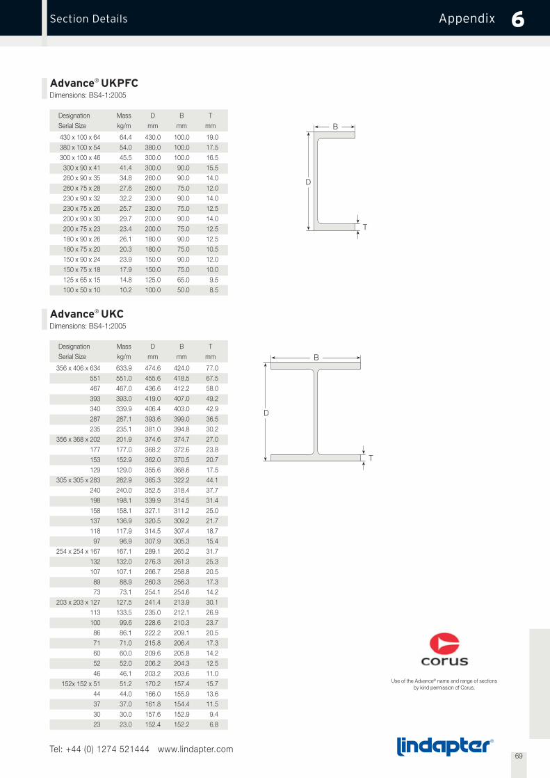
69Tel: +44 (0) 1274 521444 www.lindapter.com
AppendixSection Details 6
Advance® UKCDimensions: BS4-1:2005
Advance® UKPFCDimensions: BS4-1:2005
B
D
T
B
D
T
Designation Mass D B TSerial Size kg/m mm mm mm
430 x 100 x 64 64.4 430.0 100.0 19.0380 x 100 x 54 54.0 380.0 100.0 17.5300 x 100 x 46 45.5 300.0 100.0 16.5300 x 90 x 41 41.4 300.0 90.0 15.5260 x 90 x 35 34.8 260.0 90.0 14.0260 x 75 x 28 27.6 260.0 75.0 12.0230 x 90 x 32 32.2 230.0 90.0 14.0230 x 75 x 26 25.7 230.0 75.0 12.5200 x 90 x 30 29.7 200.0 90.0 14.0200 x 75 x 23 23.4 200.0 75.0 12.5180 x 90 x 26 26.1 180.0 90.0 12.5180 x 75 x 20 20.3 180.0 75.0 10.5150 x 90 x 24 23.9 150.0 90.0 12.0150 x 75 x 18 17.9 150.0 75.0 10.0125 x 65 x 15 14.8 125.0 65.0 9.5100 x 50 x 10 10.2 100.0 50.0 8.5
Designation Mass D B TSerial Size kg/m mm mm mm
356 x 406 x 634 633.9 474.6 424.0 77.0551 551.0 455.6 418.5 67.5467 467.0 436.6 412.2 58.0393 393.0 419.0 407.0 49.2340 339.9 406.4 403.0 42.9287 287.1 393.6 399.0 36.5235 235.1 381.0 394.8 30.2
356 x 368 x 202 201.9 374.6 374.7 27.0177 177.0 368.2 372.6 23.8153 152.9 362.0 370.5 20.7129 129.0 355.6 368.6 17.5
305 x 305 x 283 282.9 365.3 322.2 44.1240 240.0 352.5 318.4 37.7198 198.1 339.9 314.5 31.4158 158.1 327.1 311.2 25.0137 136.9 320.5 309.2 21.7118 117.9 314.5 307.4 18.797 96.9 307.9 305.3 15.4
254 x 254 x 167 167.1 289.1 265.2 31.7132 132.0 276.3 261.3 25.3107 107.1 266.7 258.8 20.589 88.9 260.3 256.3 17.373 73.1 254.1 254.6 14.2
203 x 203 x 127 127.5 241.4 213.9 30.1113 133.5 235.0 212.1 26.9100 99.6 228.6 210.3 23.786 86.1 222.2 209.1 20.571 71.0 215.8 206.4 17.360 60.0 209.6 205.8 14.252 52.0 206.2 204.3 12.546 46.1 203.2 203.6 11.0
152x 152 x 51 51.2 170.2 157.4 15.744 44.0 166.0 155.9 13.637 37.0 161.8 154.4 11.530 30.0 157.6 152.9 9.423 23.0 152.4 152.2 6.8
Use of the Advance® name and range of sectionsby kind permission of Corus.

70Tel: +44 (0) 1274 521444 www.lindapter.com
AppendixGeneral Enquiries 6
General Enquiries
Please send us: ❍ Catalogue ❍ CD ❍ CPD Booking Form
❍ The following samples:
. . . . . . . . . . . . . . . . . . . . . . . . . . . . . . . . . . . . . . . . . . . . . . . . . . . . . . . . . . . . . . . . . . . . . . . . . . . . . . . . . . . . . . . . . . . . . . . . . . . . . . . . . . . . . . .
. . . . . . . . . . . . . . . . . . . . . . . . . . . . . . . . . . . . . . . . . . . . . . . . . . . . . . . . . . . . . . . . . . . . . . . . . . . . . . . . . . . . . . . . . . . . . . . . . . . . . . . . . . . . . . .
. . . . . . . . . . . . . . . . . . . . . . . . . . . . . . . . . . . . . . . . . . . . . . . . . . . . . . . . . . . . . . . . . . . . . . . . . . . . . . . . . . . . . . . . . . . . . . . . . . . . . . . . . . . . . . .
Lindapter would like to keep you informed about the latest developments which could be valuable for you.
❍ Yes, I would like to be up-dated on new developments.
❍ I am particularly interested in the following:
. . . . . . . . . . . . . . . . . . . . . . . . . . . . . . . . . . . . . . . . . . . . . . . . . . . . . . . . . . . . . . . . . . . . . . . . . . . . . . . . . . . . . . . . . . . . . . . . . . . . . . . . . . . . . . .
. . . . . . . . . . . . . . . . . . . . . . . . . . . . . . . . . . . . . . . . . . . . . . . . . . . . . . . . . . . . . . . . . . . . . . . . . . . . . . . . . . . . . . . . . . . . . . . . . . . . . . . . . . . . . . .
❍ Please contact me. I have questions regarding:
. . . . . . . . . . . . . . . . . . . . . . . . . . . . . . . . . . . . . . . . . . . . . . . . . . . . . . . . . . . . . . . . . . . . . . . . . . . . . . . . . . . . . . . . . . . . . . . . . . . . . . . . . . . . . . .
. . . . . . . . . . . . . . . . . . . . . . . . . . . . . . . . . . . . . . . . . . . . . . . . . . . . . . . . . . . . . . . . . . . . . . . . . . . . . . . . . . . . . . . . . . . . . . . . . . . . . . . . . . . . . . .
. . . . . . . . . . . . . . . . . . . . . . . . . . . . . . . . . . . . . . . . . . . . . . . . . . . . . . . . . . . . . . . . . . . . . . . . . . . . . . . . . . . . . . . . . . . . . . . . . . . . . . . . . . . . . . .
Fax: +44 (0) 1274 521130Email: [email protected]
Your details will only be used internally and not disclosed to third parties.
Date . . . . . . . . . . . . . . . . . . . . . . . . . . . . . . . . . . . . . . . . . . . . . . . .
Company . . . . . . . . . . . . . . . . . . . . . . . . . . . . . . . . . . . . . . . . . . . . . . . . . . . . . . . . . . . . . . . . . . . . . . . . . . . . . . . . . . . . . . . . . . . . . . . . . . . . . . .
Full Name . . . . . . . . . . . . . . . . . . . . . . . . . . . . . . . . . . . . . . . . . . . . . . . . . . . . . . . . . . . . . . . . . . . . . . . . . . . . . . . . . . . . . . . . . . . . . . . . . . . . . . .
Position . . . . . . . . . . . . . . . . . . . . . . . . . . . . . . . . . . . . . . . . . . . . . . . . . . Department . . . . . . . . . . . . . . . . . . . . . . . . . . . . . . . . . . . . . . . . . .
Address . . . . . . . . . . . . . . . . . . . . . . . . . . . . . . . . . . . . . . . . . . . . . . . . . . . . . . . . . . . . . . . . . . . . . . . . . . . . . . . . . . . . . . . . . . . . . . . . . . . . . . . .
Town . . . . . . . . . . . . . . . . . . . . . . . . . . . . . . . . . . . . . . . . . . . . . . . . . . . . Postcode . . . . . . . . . . . . . . . . . . . . . . . . . . . . . . . . . . . . . . . . . . . .
Tel . . . . . . . . . . . . . . . . . . . . . . . . . . . . . . . . . . . . . . . . . . . . . . . . . . . . . . Fax . . . . . . . . . . . . . . . . . . . . . . . . . . . . . . . . . . . . . . . . . . . . . . . . .
E-mail . . . . . . . . . . . . . . . . . . . . . . . . . . . . . . . . . . . . . . . . . . . . . . . . . . . . Web www . . . . . . . . . . . . . . . . . . . . . . . . . . . . . . . . . . . . . . . . .

71Tel: +44 (0) 1274 521444 www.lindapter.com
AppendixProjects 6
Canary Wharf, London St Pancras Station, London
Offshore Rig, North Sea BMW World, Munich
New Chinese National Theatre, Beijing Viaduc de Millau, France
Wembley Stadium, London Tower Bridge, London

Lindsay HouseBrackenbeck RoadBradfordWest YorkshireBD7 2NFEngland
T: +44 (0) 1274 521444F: +44 (0) 1274 521130E: [email protected]
www.lindapter.com
LindUK
Feb09LindU
KJan10
Top Related