


Languages
Pages
Legal


TI365F/00/en
Technical Information
Prosonic M FMU40/41/42/43/44Ultrasonic Level Measurement
Compact transmitters for non-contact level measurement of fluids,
pastes and coarse bulk materials
Application
• Continuous, non-contact level measurement in fluids,
pastes, sullages and coarse bulk materials
• Flow measurement in open channels and measuring
weirs
• System integration via:
– HART (standard), 4...20mA
– PROFIBUS PA
– Foundation Fieldbus
• Maximum measuring range:
– FMU 40:
5 m in fluids / 2 m in bulk materials
– FMU 41:
8 m in fluids / 3,5 m in bulk materials
– FMU 42:
10 m in fluids / 5 m in bulk materials
– FMU 43:
15 m in fluids / 7 m in bulk materials
– FMU44:
20 m in fluids / 10 m in bulk materials
Features and benefits
• Quick and simple commissioning via menu-guided on-
site operation with four-line plain text display
• Envelope curves on the on-site display for simple
diagnosis
• Easy remote operation, diagnosis and measuring point
documentation with the supplied ToF Tool operating
program.
• Suitable for explosion hazardous areas
(Gas-Ex, Dust-Ex)
• Linearisation function (up to 32 points) for conversion
of the measured value into any unit of length, volume
or flow rate
• Non-contact measurement method minimizes service
requirements
• optional remote display and operation (up to 20 m
from transmitter)
• Installation possible from thread G 1½“ or 1½ NPT
upwards
• Integrated temperature sensor for automatic
correction of the temperature dependent sound
velocity

Inhaltsverzeichnis
Function and system design. . . . . . . . . . . . . . . . . . . . . 3 Process conditions . . . . . . . . . . . . . . . . . . . . . . . . . . . 21
Measuring principle . . . . . . . . . . . . . . . . . . . . . . . . . . . . . . . . . . . 3
Equipment architecture . . . . . . . . . . . . . . . . . . . . . . . . . . . . . . . . 4
Input . . . . . . . . . . . . . . . . . . . . . . . . . . . . . . . . . . . . . . 8
Measured variable . . . . . . . . . . . . . . . . . . . . . . . . . . . . . . . . . . . . 8
Measuring range . . . . . . . . . . . . . . . . . . . . . . . . . . . . . . . . . . . . . . 8
Operating frequency . . . . . . . . . . . . . . . . . . . . . . . . . . . . . . . . . . . 9
Output . . . . . . . . . . . . . . . . . . . . . . . . . . . . . . . . . . . . 10
Output signal . . . . . . . . . . . . . . . . . . . . . . . . . . . . . . . . . . . . . . . 10
Signal on alarm . . . . . . . . . . . . . . . . . . . . . . . . . . . . . . . . . . . . . 10
Load HART . . . . . . . . . . . . . . . . . . . . . . . . . . . . . . . . . . . . . . . . 10
Output damping . . . . . . . . . . . . . . . . . . . . . . . . . . . . . . . . . . . . . 10
Linearisation . . . . . . . . . . . . . . . . . . . . . . . . . . . . . . . . . . . . . . . 10
Auxiliary energy . . . . . . . . . . . . . . . . . . . . . . . . . . . . 11
Terminal compartment . . . . . . . . . . . . . . . . . . . . . . . . . . . . . . . . 11
Terminal assignment . . . . . . . . . . . . . . . . . . . . . . . . . . . . . . . . . 11
Fieldbus plug connectors . . . . . . . . . . . . . . . . . . . . . . . . . . . . . . 12
Supply voltage . . . . . . . . . . . . . . . . . . . . . . . . . . . . . . . . . . . . . . 13
Terminals . . . . . . . . . . . . . . . . . . . . . . . . . . . . . . . . . . . . . . . . . . 13
Cable entry . . . . . . . . . . . . . . . . . . . . . . . . . . . . . . . . . . . . . . . . 13
Power consumption . . . . . . . . . . . . . . . . . . . . . . . . . . . . . . . . . . 13
Current consumption
(2-wire-instruments) . . . . . . . . . . . . . . . . . . . . . . . . . . . . . . . . . 13
HART ripple . . . . . . . . . . . . . . . . . . . . . . . . . . . . . . . . . . . . . . . . 14
Max. noise HART . . . . . . . . . . . . . . . . . . . . . . . . . . . . . . . . . . . . 14
Galvanic isolation . . . . . . . . . . . . . . . . . . . . . . . . . . . . . . . . . . . . 14
Performance characteristics. . . . . . . . . . . . . . . . . . . . 15
Reaction time . . . . . . . . . . . . . . . . . . . . . . . . . . . . . . . . . . . . . . . 15
Reference operating conditions . . . . . . . . . . . . . . . . . . . . . . . . . . 15
Measured value resolution . . . . . . . . . . . . . . . . . . . . . . . . . . . . . 15
Pulse frequency . . . . . . . . . . . . . . . . . . . . . . . . . . . . . . . . . . . . . 15
Measuring error . . . . . . . . . . . . . . . . . . . . . . . . . . . . . . . . . . . . . 15
Installation conditions . . . . . . . . . . . . . . . . . . . . . . . . 16
Installation variants FMU 40, FMU 41 . . . . . . . . . . . . . . . . . . . . 16
Installation variants FMU42, FMU44 . . . . . . . . . . . . . . . . . . . . . 16
Installation variants FMU 43 . . . . . . . . . . . . . . . . . . . . . . . . . . . . 17
Installation conditions for level measurements . . . . . . . . . . . . . . 17
Installation in narrow shafts . . . . . . . . . . . . . . . . . . . . . . . . . . . . 18
Installation conditions for flow measurements . . . . . . . . . . . . . . . 18
Blocking distance,
nozzle installation . . . . . . . . . . . . . . . . . . . . . . . . . . . . . . . . . . . 20
Ambient conditions . . . . . . . . . . . . . . . . . . . . . . . . . . 21
Ambient temperature . . . . . . . . . . . . . . . . . . . . . . . . . . . . . . . . . 21
Storage temperature . . . . . . . . . . . . . . . . . . . . . . . . . . . . . . . . . . 21
Resistance to alternating
temperature cycles . . . . . . . . . . . . . . . . . . . . . . . . . . . . . . . . . . . 21
Climate class . . . . . . . . . . . . . . . . . . . . . . . . . . . . . . . . . . . . . . . 21
Ingress protection . . . . . . . . . . . . . . . . . . . . . . . . . . . . . . . . . . . . 21
Vibration resistance . . . . . . . . . . . . . . . . . . . . . . . . . . . . . . . . . . 21
Electromagnetic compatibility (EMC) . . . . . . . . . . . . . . . . . . . . . 21
2
Process temperature . . . . . . . . . . . . . . . . . . . . . . . . . . . . . . . . . . 21
Process pressure . . . . . . . . . . . . . . . . . . . . . . . . . . . . . . . . . . . . . 21
Mechanical construction . . . . . . . . . . . . . . . . . . . . . . 22
Design; dimensions . . . . . . . . . . . . . . . . . . . . . . . . . . . . . . . . . . 22
Weight . . . . . . . . . . . . . . . . . . . . . . . . . . . . . . . . . . . . . . . . . . . 24
Housing design . . . . . . . . . . . . . . . . . . . . . . . . . . . . . . . . . . . . . 25
Process connection,
sealing material,
sensor material . . . . . . . . . . . . . . . . . . . . . . . . . . . . . . . . . . . . . . 25
Human interface . . . . . . . . . . . . . . . . . . . . . . . . . . . . 26
Display and operating elements . . . . . . . . . . . . . . . . . . . . . . . . . 26
On-site operation . . . . . . . . . . . . . . . . . . . . . . . . . . . . . . . . . . . . 27
Remote operation . . . . . . . . . . . . . . . . . . . . . . . . . . . . . . . . . . . . 28
Certificates and Approvals . . . . . . . . . . . . . . . . . . . . . 30
CE mark . . . . . . . . . . . . . . . . . . . . . . . . . . . . . . . . . . . . . . . . . . 30
Ex approval . . . . . . . . . . . . . . . . . . . . . . . . . . . . . . . . . . . . . . . . 30
External standards and guidelines . . . . . . . . . . . . . . . . . . . . . . . . 30
Ordering information. . . . . . . . . . . . . . . . . . . . . . . . . 31
Product structure FMU 40 . . . . . . . . . . . . . . . . . . . . . . . . . . . . . 31
Product structure FMU 41 . . . . . . . . . . . . . . . . . . . . . . . . . . . . . 32
Product structure FMU 42 . . . . . . . . . . . . . . . . . . . . . . . . . . . . . 33
Product structure FMU 43 . . . . . . . . . . . . . . . . . . . . . . . . . . . . . 34
Product structure FMU 44 . . . . . . . . . . . . . . . . . . . . . . . . . . . . . 35
Scope of delivery . . . . . . . . . . . . . . . . . . . . . . . . . . . . . . . . . . . . 36
Accessories . . . . . . . . . . . . . . . . . . . . . . . . . . . . . . . . 37
Weather protection cover . . . . . . . . . . . . . . . . . . . . . . . . . . . . . . 37
Installation bracket for FMU 40/41 . . . . . . . . . . . . . . . . . . . . . . 37
Adapter flange . . . . . . . . . . . . . . . . . . . . . . . . . . . . . . . . . . . . . . 38
Cantilever . . . . . . . . . . . . . . . . . . . . . . . . . . . . . . . . . . . . . . . . . 39
Mounting Frame . . . . . . . . . . . . . . . . . . . . . . . . . . . . . . . . . . . . 40
Wall Bracket . . . . . . . . . . . . . . . . . . . . . . . . . . . . . . . . . . . . . . . 40
Commubox FXA191 HART . . . . . . . . . . . . . . . . . . . . . . . . . . . . 40
Commubox FXA195 HART . . . . . . . . . . . . . . . . . . . . . . . . . . . . 40
Service Interface FXA193 . . . . . . . . . . . . . . . . . . . . . . . . . . . . . . 41
Remote display FHX40 . . . . . . . . . . . . . . . . . . . . . . . . . . . . . . . . 42
Supplementary documentation . . . . . . . . . . . . . . . . . 43
System Information . . . . . . . . . . . . . . . . . . . . . . . . . . . . . . . . . . 43
Operating manual . . . . . . . . . . . . . . . . . . . . . . . . . . . . . . . . . . . 43
Description of device functions . . . . . . . . . . . . . . . . . . . . . . . . . . 43
Short instructions . . . . . . . . . . . . . . . . . . . . . . . . . . . . . . . . . . . . 43
Safety Instructions ATEX . . . . . . . . . . . . . . . . . . . . . . . . . . . . . . 43
Safety Instructions NEPSI . . . . . . . . . . . . . . . . . . . . . . . . . . . . . . 45
Control drawings Installation drawings . . . . . . . . . . . . . . . . . . . . 46
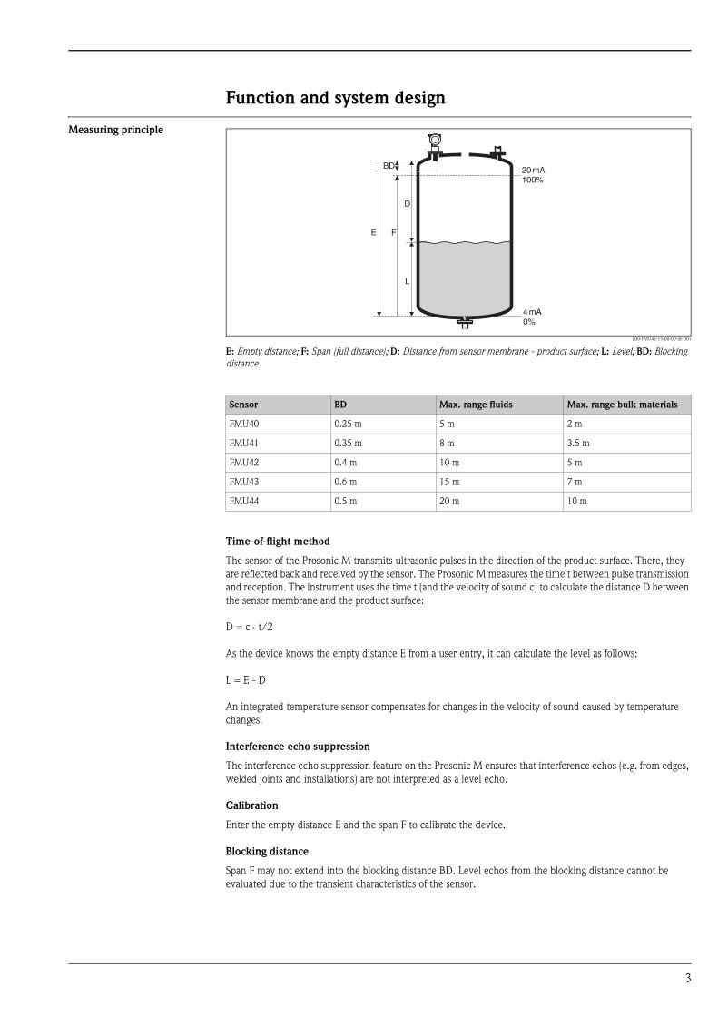
Function and system design
Measuring principle
L00-FMU4x-15-00-00-de-001
E: Empty distance; F: Span (full distance); D: Distance from sensor membrane - product surface; L: Level; BD: Blocking distance
Time-of-flight method
The sensor of the Prosonic M transmits ultrasonic pulses in the direction of the product surface. There, they
are reflected back and received by the sensor. The Prosonic M measures the time t between pulse transmission
and reception. The instrument uses the time t (and the velocity of sound c) to calculate the distance D between
the sensor membrane and the product surface:
D = c ⋅ t/2
As the device knows the empty distance E from a user entry, it can calculate the level as follows:
L = E - D
An integrated temperature sensor compensates for changes in the velocity of sound caused by temperature
changes.
Interference echo suppression
The interference echo suppression feature on the Prosonic M ensures that interference echos (e.g. from edges,
welded joints and installations) are not interpreted as a level echo.
Calibration
Enter the empty distance E and the span F to calibrate the device.
Blocking distance
Span F may not extend into the blocking distance BD. Level echos from the blocking distance cannot be
evaluated due to the transient characteristics of the sensor.
20mA100%
4mA0%
D
L
FE
BD
Sensor BD Max. range fluids Max. range bulk materials
FMU40 0.25 m 5 m 2 m
FMU41 0.35 m 8 m 3.5 m
FMU42 0.4 m 10 m 5 m
FMU43 0.6 m 15 m 7 m
FMU44 0.5 m 20 m 10 m
3

Equipment architecture 4…20 mA output with HART protocol
The complete measuring system consists of:
L00-FMxxxxxx-14-00-06-en-007
If the HART communication resistor is not built into the supply unit, it is necessary to insert a communication
resistor of 250 Ω into the 2-wire line.
On-site operation
• with display and operating module VU 331
• with a Personal Computer, FXA 193 and the operating software ToF Tool
Remote operation
• with HART handheld terminal DXR 375
• with a Personal Computer, Commubox FXA 191 and the operating software COMMUWIN II respectively
ToF Tool.
ENDRESS + HAUSER
E+–
%
ENDRESS + HAUSERRMA 422
1# % &
Copy
G H I
P Q R S
, ( ) ‘
A B C
Paste
PageOn
PageUp
DeleteBksp
Insert
J K L
T U V
_ < >
D E F
Hot Key
+ Hot Key
M N O
W X Y Z
+ * /
4
7
.
2
5
8
0
375FIELD COMMUNICATOR
3
6
9
-
9 6
DELTABAR: * * * * * * * *ONLINE
1 QUICK SETUP2 OPERATING MENU
4 SV 0 °C3 PV 352 mbar
HELP SAVE
dsdmdmdf das.
asdas faasas la.
FieldCare
FieldCare
HART handheldField Communicator 375FXA191/195
Field Commu-nicator 375
transmitter powersupply unitRMA422or RN221N(communication resistorincluded)
PLC
CommuboxFXA191/195
operating anddisplay moduleVU331
Power supply(for 4-wire)
service adapter• FXA291/ToF Adapter FXA291• FXA193
4

System integration using PROFIBUS PA
A maximum of 32 transmitters (8 if mounted in an explosion hazardous location EEx ia IIC according to
FISCO-model) can be connected to the bus.The segment coupler provides the operating voltage to the bus.
Both on-site as well as remote operation are possible.
L00-FMxxXXXX-14-00-06-en-001
System integration using Foundation Fieldbus (FF)
A maximum of 32 transmitters (standard or EEx d) can be connected to the bus. For protection class EEx ia:
the maximum number of transmitters depends on the established rules and standards for intrinsically safe
circuits (EN 60070-14) and proof of instrinsic safety. Both on-site and remote operation are possible.
L00-FMxxXXXX-14-00-06-en-003
ENDRESS + HAUSER
Micropilot M Prosonic M
Levelflex M
ENDRESS + HAUSER
E+–
%
T
PROFIBUS DP
PROFIBUS PA
FieldCare
personal computer withFieldCare andProfibard resp. Proficard
segment coupler
PLC
operating anddisplay moduleVU331
MoreFunctions(valves etc)
service adapter• FXA291/ToF Adapter FXA291• FXA193
T TFF link
Levelflex M
ENDRESS + HAUSER
E+–
%
Prosonic MMicropilot MFieldCare
personal computere.g. withNI-FBUS configurator
operating anddisplay moduleVU331
power supply
power conditioner
power supply
power conditioner
Additionalfunctions(valves etc.)
service adapter• FXA291/ToF Adapter FXA291• FXA193
5

System integration using Endress+Hauser Rackbus
You can interconnect a maximum of 64 2-wire devices with HART protocol to a Rackbus. Use an FXN 672
interface module for each device. You can integrate this bus into a higher-level bus by using a ZA gateway.
Gateways are available for MODBUS, FIP, PROFIBUS, INTERBUS etc. Both on-site and remote operation are
possible.
L00-FMxxXXXX-14-00-06-en-006
! Hinweis!
The FXN672 can be used with all 2-wire devices of the Prosonic M family.
FXN 671
mA1+
FXN 671
mA1+
FXN 671
mA1+
ZA 672 ZA 672
FXA193Micropilot M Prosonic M
Levelflex M
ENDRESS + HAUSER
E+–
%
ToF Tool - FieldTool Package
personal computerwith Commuwin II
PLC
operating anddisplay moduleVU331
BusRS 232C
Gateway toMODBUS, FIP,PROFIBUS,INTERBUS etc.
FXN672
4…20 mA with HART
6
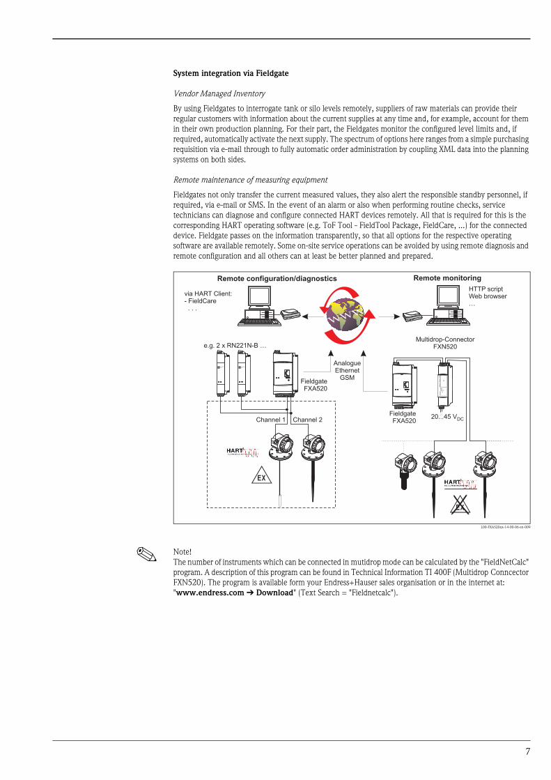
System integration via Fieldgate
Vendor Managed Inventory
By using Fieldgates to interrogate tank or silo levels remotely, suppliers of raw materials can provide their
regular customers with information about the current supplies at any time and, for example, account for them
in their own production planning. For their part, the Fieldgates monitor the configured level limits and, if
required, automatically activate the next supply. The spectrum of options here ranges from a simple purchasing
requisition via e-mail through to fully automatic order administration by coupling XML data into the planning
systems on both sides.
Remote maintenance of measuring equipment
Fieldgates not only transfer the current measured values, they also alert the responsible standby personnel, if
required, via e-mail or SMS. In the event of an alarm or also when performing routine checks, service
technicians can diagnose and configure connected HART devices remotely. All that is required for this is the
corresponding HART operating software (e.g. ToF Tool - FieldTool Package, FieldCare, ...) for the connected
device. Fieldgate passes on the information transparently, so that all options for the respective operating
software are available remotely. Some on-site service operations can be avoided by using remote diagnosis and
remote configuration and all others can at least be better planned and prepared.
L00-FXA520xx-14-00-06-en-009
! Note!
The number of instruments which can be connected in mutidrop mode can be calculated by the "FieldNetCalc"
program. A description of this program can be found in Technical Information TI 400F (Multidrop Conncector
FXN520). The program is available form your Endress+Hauser sales organisation or in the internet at:
"www.endress.com É Download" (Text Search = "Fieldnetcalc").
-
FieldgateFXA520
ENDRESS+HAUSERRN 221N
ENDRESS+HAUSERRN 221N
.
FieldgateFXA520
20...45 VDC
FX
N520
FX
N520
Multidrop-ConnectorFXN520
HTTP scriptWeb browser…
AnalogueEthernet
GSM
e.g. 2 x RN221N-B …
Channel 1 Channel 2
via HART Client:- FieldCare. . .
Remote monitoringRemote configuration/diagnostics
7
Input
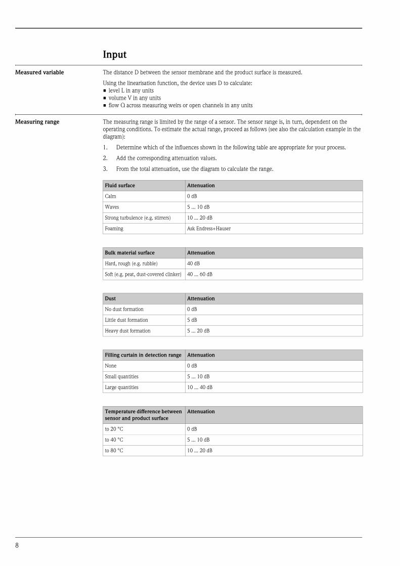
Measured variable The distance D between the sensor membrane and the product surface is measured.
Using the linearisation function, the device uses D to calculate:
• level L in any units
• volume V in any units
• flow Q across measuring weirs or open channels in any units
Measuring range The measuring range is limited by the range of a sensor. The sensor range is, in turn, dependent on the
operating conditions. To estimate the actual range, proceed as follows (see also the calculation example in the
diagram):
1. Determine which of the influences shown in the following table are appropriate for your process.
2. Add the corresponding attenuation values.
3. From the total attenuation, use the diagram to calculate the range.
Fluid surface Attenuation
Calm 0 dB
Waves 5 ... 10 dB
Strong turbulence (e.g. stirrers) 10 ... 20 dB
Foaming Ask Endress+Hauser
Bulk material surface Attenuation
Hard, rough (e.g. rubble) 40 dB
Soft (e.g. peat, dust-covered clinker) 40 ... 60 dB
Dust Attenuation
No dust formation 0 dB
Little dust formation 5 dB
Heavy dust formation 5 ... 20 dB
Filling curtain in detection range Attenuation
None 0 dB
Small quantities 5 ... 10 dB
Large quantities 10 ... 40 dB
Temperature difference between
sensor and product surface
Attenuation
to 20 °C 0 dB
to 40 °C 5 ... 10 dB
to 80 °C 10 ... 20 dB
8

L00-FMU4xxxx-05-00-00-en-002
Example (for FMU 43)
For typical solid applications, a certain amount of dust coverage is normally present. Therefore, the following
range results from the table and the diagram
These measuring conditions have been taken into account during the calculation of the maximum measuring
range in solid applications.
Operating frequency
• Dust-covered rubble approx. 50 dB
• no dust formation 0 dB
• No filling curtain in
detection range 0 dB
• Temperature diff. < 20°C 0 dB
approx. 50 dB => range approx. 7 m
FMU 40
FMU 41
FMU 43
10 20 30 40 50 60 70 80
1
2
3
4
5
6
7
8
9
10
11
12
13
14
15
FMU 42
16
17
18
19
20FMU 44
attenuation / dB
rang
e/ m
Sensor Operating frequency
FMU40 approx. 70 kHz
FMU41 approx. 50 kHz
FMU42 approx. 42 kHz
FMU43 approx. 35 kHz
FMU44 approx. 30 kHz
9
Output
Output signal according to the instrument version ordered:
• 4…20 mA with HART protocol
• PROFIBUS PA
• Foundation Fieldbus (FF)
Signal on alarm Error information can be accessed via the following interfaces:
• On-site display (error symbol, error code and plain text description)
• Current output (error current configurable)
• Digital interface
Load HART Minimum load for HART communication: 250 Ω
Output damping Freely selectable, 0 ... 255 s
Linearisation The linearisation function of the Prosonic M allows conversion of the measured value into any unit of length
or volume. In open channels or measuring weirs, also a flow linearistion is possible (calculation of the flow from
the measured level). The linearisation table for calculating the volume in an horizontal cylindrical tank is
preprogrammed. You can also enter any number of other tables containing up to 32 value pairs either manually
or semi-automatically (by filling the vessel under controlled conditions).
The supplied ToF Tool operating program can automatically calculate the table for any tank, weir or flume and
upload it into the device.
Flow curves for open channels can be calculated and entered into the instrument by the ToT Tool as well.
10

Auxiliary energy
Terminal compartment In the F12 housing, the terminals are located underneath the housing cover. In the T12 housing, they are under
the cover of the separate terminal compartment.
L00-FMR2xxxx-04-00-00-en-001
Terminal assignment
• Connect the connecting line to the screw terminals (line cross-sections of 0.5 ... 2.5mm) in the terminal
compartment.
• Use 2-wire twisted pair cable with screen for the connection.
• Protective circuitry against reverse polarity, RFI and over-voltage peaks is built into the device (see also
Technical Information TI 241F/00/en "EMC Test Procedures")
sealed terminalcompartment
F12 housing T12 housing
4 ... 20 mA with HART, 2-wire
L00-FMxxxxxx-04-00-00-en-015
4 ... 20 mA active with HART, 4-wire
L00-FMxxxxxx-04-00-00-en-011
3 4I+ I-
1 2L- L+
4...20 mA
CommuboxFXA191/195Field Communicator 375
communicationresistor(> 250 )W
alternatively
plantground
test sockets for testingof the signal current
power
5 6I+ I-
1 2L1/L+ N/L-
4...20mA
CommuboxFXA191/195Field Commu-nicator 375
communicationresistor(> 250 )W
alternatively
powerdisplay unit,recorder, PCS
AC / DCDC
plantground
11

The digital communication signal is transmitted to the bus via a 2-wire connection. The bus also provides the
auxiliary energy. Use 2-wire twisted pair cable with screen.
Refer to the following operating manuals for information on cable types, and how to set up and ground the
network:
• BA 198F/00/de „PROFIBIS -DP/-PA, Guidelines for planning and commissioning“
• BA 013S/04/en „Foundation Fieldbus, Installation and Commissioning Guidelines“
Fieldbus plug connectors For the versions with fieldbus plug connector (M12 or 7/8"), the signal line can be connected without opening
the housing.
Pin assignment of the M12 plug connector (PROFIBUS PA plug)
Pin assignment of the 7/8" plug connector (FOUNDATION Fieldbus plug)
PROFIBUS PA
L00-FMxxxxxx-04-00-00-en-012
Foundation Fieldbus
L00-FMxxxxxx-04-00-00-en-013
3 41 2+–
T-BoxPROFIBUS PA
plantground
3 41 2+–
plantground
L00-FMxxxxxx-04-00-00-yy-016
Pin Meaning
1 Ground
2 Signal +
3 Signal -
4 not connected
L00-FMxxxxxx-04-00-00-yy-017
Pin Meaning
1 Signal -
2 Signal +
3 not connected
4 ground
2
1 3
4+
–
nc
2
1 3
4+
– nc
12
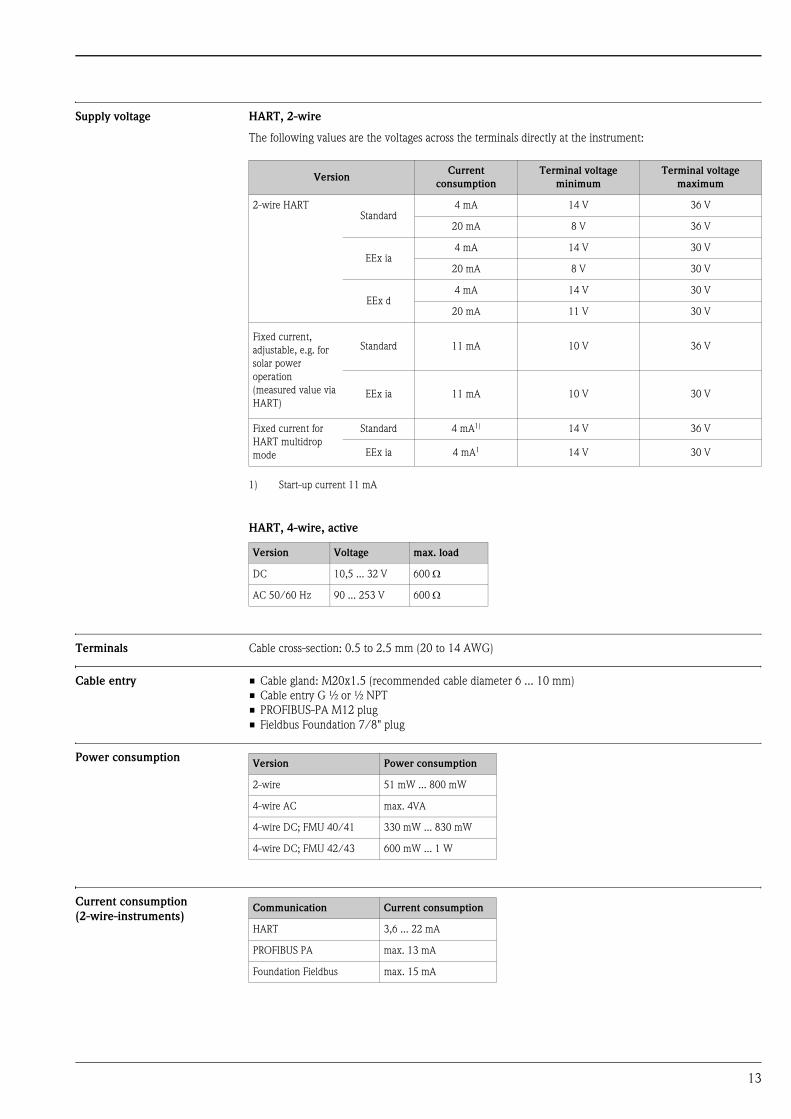
Supply voltage HART, 2-wire
The following values are the voltages across the terminals directly at the instrument:
HART, 4-wire, active
Terminals Cable cross-section: 0.5 to 2.5 mm (20 to 14 AWG)
Cable entry • Cable gland: M20x1.5 (recommended cable diameter 6 ... 10 mm)
• Cable entry G ½ or ½ NPT
• PROFIBUS-PA M12 plug
• Fieldbus Foundation 7/8" plug
Power consumption
Current consumption
(2-wire-instruments)
VersionCurrent
consumption
Terminal voltage
minimum
Terminal voltage
maximum
2-wire HARTStandard
4 mA 14 V 36 V
20 mA 8 V 36 V
EEx ia4 mA 14 V 30 V
20 mA 8 V 30 V
EEx d4 mA 14 V 30 V
20 mA 11 V 30 V
Fixed current,
adjustable, e.g. for
solar power
operation
(measured value via
HART)
Standard 11 mA 10 V 36 V
EEx ia 11 mA 10 V 30 V
Fixed current for
HART multidrop
mode
Standard 4 mA1)
1) Start-up current 11 mA
14 V 36 V
EEx ia 4 mA1 14 V 30 V
Version Voltage max. load
DC 10,5 ... 32 V 600 Ω
AC 50/60 Hz 90 ... 253 V 600 Ω
Version Power consumption
2-wire 51 mW ... 800 mW
4-wire AC max. 4VA
4-wire DC; FMU 40/41 330 mW ... 830 mW
4-wire DC; FMU 42/43 600 mW ... 1 W
Communication Current consumption
HART 3,6 ... 22 mA
PROFIBUS PA max. 13 mA
Foundation Fieldbus max. 15 mA
13

HART ripple 47...125 Hz: Vpp = 200 mV (measured at 500 Ω)
Max. noise HART 500 Hz...10 kHz: Vrms = 2.2 mV (measured at 500 Ω)
Galvanic isolation With 4-wire devices, the evaluation electronics and mains voltage are galvanically isolated from each other.
14
Performance characteristics
Reaction time The reaction time depends on the parameter settings. The minimum values are:
• 2-wire devices (FMU40/41/42): min. 2 s
• 2-wire diveces (FMU43 - PROFIBUS PA or FOUNDATION Fieldbus): min. 2 s
• 2-wire devices (FMU44): min. 3 s
• 4-wire devices (FMU40/41/42/43/44): 0.5 s
Reference operating
conditions
• Temperature = +20 °C
• Pressure = 1013 mbar abs.
• Humidity = 50 %
• Ideal reflective surface (e.g. calm, smooth fluid surface)
• No interference reflections within signal beam
• Set application parameters:
– Tank shape = flat ceiling
– Medium property = liquid
– process conditions = calm surface
Measured value resolution
Pulse frequency • 2-wire devices (FMU40/41/42): max. 0.5Hz
• 2-wire devices (FMU43 - PROFIBUS PA or FOUNDATION Fieldbus): max. 0.5 Hz
• 2-wire devices (FMU44): max. 0.3 Hz
• 4-wire devices (FMU40/41/42/43/44): max. 2Hz
The exact values are dependent on the type of device and the parameter settings.
Measuring error Typical specifications for reference operating conditions (include linearity, repeatability, and hysteresis):
1whichever is greater
Sensor Measured value resolution
FMU40 1 mm
FMU41 1 mm
FMU42 2 mm
FMU43 2 mm
FMU44 2 mm
Sensor Measuring error
FMU40 ±2mm or 0.2% of set measuring distance (empty calibration)1
FMU41 ± 2 mm or 0,2% of set measuring distance (empty calibration)1
FMU42 ± 4 mm or 0,2% of set measuring distance (empty calibration)1
FMU43 ± 4 mm or 0,2% of set measuring distance (empty calibration)1
FMU44 ± 4 mm or 0,2% of set measuring distance (empty calibration)1
15

Installation conditions
Installation variants FMU 40,
FMU 41
L00-FMU4xxxx-17-00-00-en-002
For installation bracket or adapter flange s. chapter "Accessories".
Installation variants FMU42,
FMU44
L00-FMU42xxxx-17-00-00-en-001
ENDRESS+HAUSERProsonic M
Installation with sleeveInstallation with counter nut
Installation with installation bracket
counter nut (PC)suppliedfor G 1½” andG 2” instruments
adapter flange
sensor nozzle
Sealing ring(EPDM)supplied
Installation with adapter flange
Sealing ring(EPDM)supplied
ENDRESS+HAUSER
Prosonic M
- .
Installation with universal flange Installation with mounting bracket
e.g. Zone 20 Zone 20
16
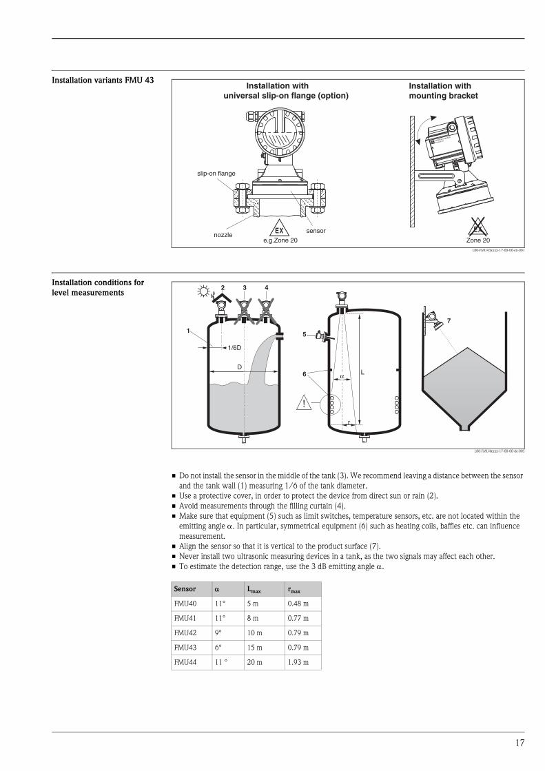
Installation variants FMU 43
L00-FMU43xxxx-17-00-00-en-001
Installation conditions for
level measurements
L00-FMU4xxxx-17-00-00-de-005
• Do not install the sensor in the middle of the tank (3). We recommend leaving a distance between the sensor
and the tank wall (1) measuring 1/6 of the tank diameter.
• Use a protective cover, in order to protect the device from direct sun or rain (2).
• Avoid measurements through the filling curtain (4).
• Make sure that equipment (5) such as limit switches, temperature sensors, etc. are not located within the
emitting angle α. In particular, symmetrical equipment (6) such as heating coils, baffles etc. can influence
measurement.
• Align the sensor so that it is vertical to the product surface (7).
• Never install two ultrasonic measuring devices in a tank, as the two signals may affect each other.
• To estimate the detection range, use the 3 dB emitting angle α.
ENDRESS+HAUSER
Prosonic M
- .Zone 20
Installation withmounting bracket
Installation withuniversal slip-on flange (option)
slip-on flange
sensornozzle
e.g.Zone 20
1
2 3 4
5
6
1/6D
7
D
r
α L
Sensor α Lmax rmax
FMU40 11° 5 m 0.48 m
FMU41 11° 8 m 0.77 m
FMU42 9° 10 m 0.79 m
FMU43 6° 15 m 0.79 m
FMU44 11 ° 20 m 1.93 m
17
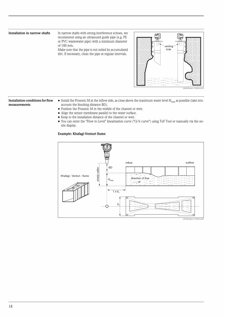
Installation in narrow shafts
Installation conditions for flow
measurements
• Install the Prosonic M at the inflow side, as close above the maximum water level Hmax as possible (take into
account the blocking distance BD).
• Position the Prosonic M in the middle of the channel or weir.
• Align the sensor membrane parallel to the water surface.
• Keep to the installation distance of the channel or weir.
• You can enter the "Flow to Level" linearisation curve ("Q/h curve") using ToF Tool or manually via the on-
site display.
Example: Khafagi-Venturi flume
L00-FMU4xxxx-17-00-00-en-003
In narrow shafts with strong interference echoes, we
recommend using an ultrasound guide pipe (e.g. PE
or PVC wastewater pipe) with a minimum diameter
of 100 mm.
Make sure that the pipe is not soiled by accumulated
dirt. If necessary, clean the pipe at regular intervals.
L00-FMU4xxxx-17-00-00-en-010
ENDRESS+HAUSERProsonic MENDRESS+HAUSERProsonic M
ENDRESS+HAUSERProsonic MENDRESS+HAUSERProsonic M
ventinghole
1 x b0
b0
BD
Hmax
Khafagi - Venturi - flumedirection of flow
inflow outflow
empt
y ca
libr.
18
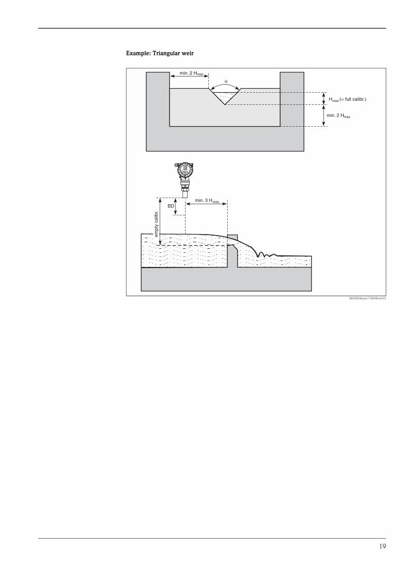
Example: Triangular weir
L00-FMU4xxxx-17-00-00-en-012
max
max
max
max
empt
y ca
libr.
(= full calibr.)
min. 3 H
H
min. 2 H
α
min. 2 H
BD
19
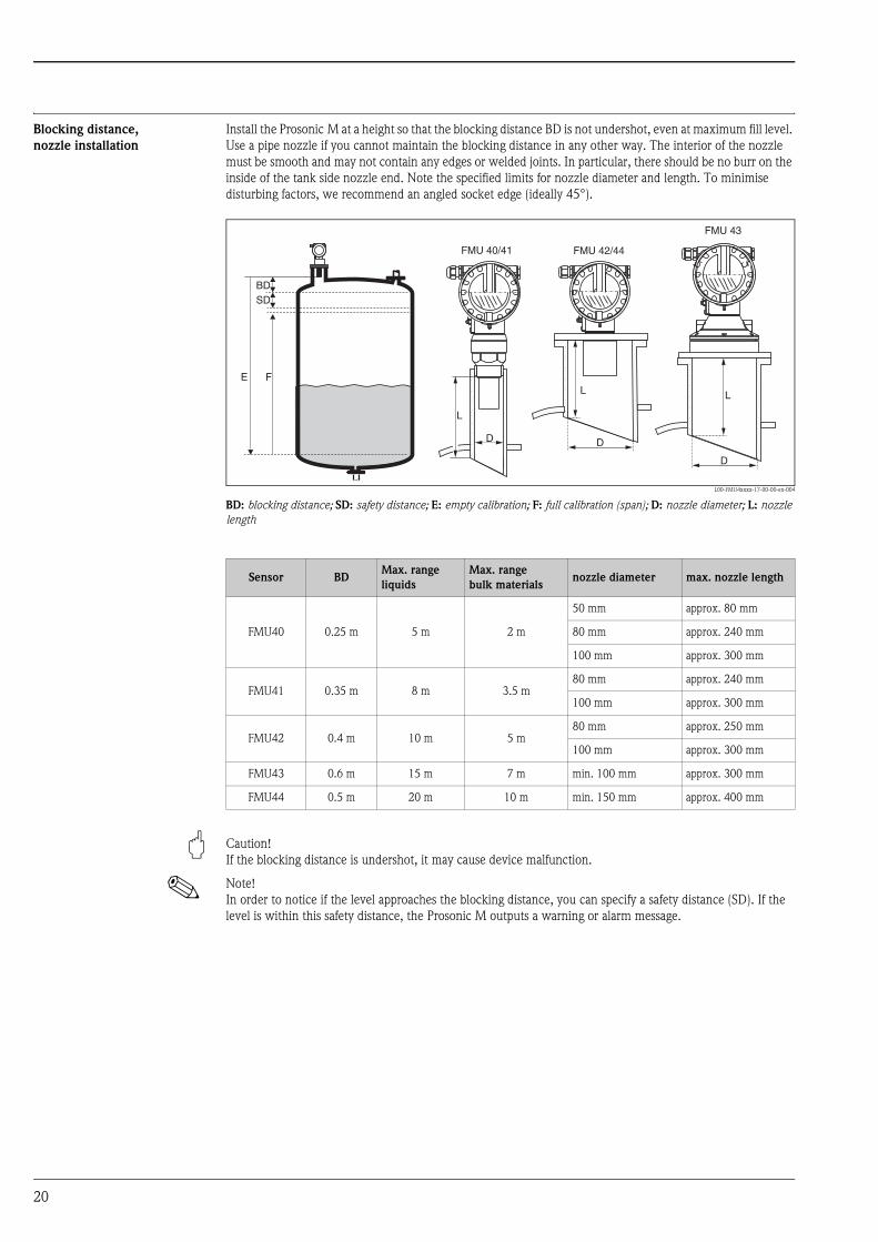
Blocking distance,
nozzle installation
Install the Prosonic M at a height so that the blocking distance BD is not undershot, even at maximum fill level.
Use a pipe nozzle if you cannot maintain the blocking distance in any other way. The interior of the nozzle
must be smooth and may not contain any edges or welded joints. In particular, there should be no burr on the
inside of the tank side nozzle end. Note the specified limits for nozzle diameter and length. To minimise
disturbing factors, we recommend an angled socket edge (ideally 45°).
L00-FMU4xxxx-17-00-00-en-004
BD: blocking distance; SD: safety distance; E: empty calibration; F: full calibration (span); D: nozzle diameter; L: nozzle length
" Caution!
If the blocking distance is undershot, it may cause device malfunction.
! Note!
In order to notice if the level approaches the blocking distance, you can specify a safety distance (SD). If the
level is within this safety distance, the Prosonic M outputs a warning or alarm message.
FE
BDSD
L
D
FMU 40/41
L
D
FMU 43
L
D
FMU 42/44
Sensor BDMax. range
liquids
Max. range
bulk materialsnozzle diameter max. nozzle length
FMU40 0.25 m 5 m 2 m
50 mm approx. 80 mm
80 mm approx. 240 mm
100 mm approx. 300 mm
FMU41 0.35 m 8 m 3.5 m80 mm approx. 240 mm
100 mm approx. 300 mm
FMU42 0.4 m 10 m 5 m80 mm approx. 250 mm
100 mm approx. 300 mm
FMU43 0.6 m 15 m 7 m min. 100 mm approx. 300 mm
FMU44 0.5 m 20 m 10 m min. 150 mm approx. 400 mm
20

Ambient conditions
Ambient temperature -40 °C ... +80 °C
The functionality of the LC display becomes restricted at Tu<-20 °C and Tu>+60 °C.
If the device is operated outdoors in strong sunlight, you should use a protective cover.
Storage temperature -40 °C ... +80 °C
Resistance to alternating
temperature cycles
to DIN EN 60068-2-14; Nb test : +80°C/-40°C, 1K/min, 100cycles
Climate class DIN EN 60068-2-38 (Test Z/AD) DIN/IEC 68 T2-30Db
Ingress protection • With closed housing, tested according to
– IP 68, NEMA 6P (24h at 1.83m under water surface)
– IP 66, NEMA 4x
• With open housing: IP 20, NEMA 1 (also ingress protection of the display)
" Caution!
Degree of protection IP 68 NEMA 6P applies for M12 PROFIBUS-PA plugs only when the PROFIBUS cable is
plugged in.
Vibration resistance DIN EN 60068-2-64 / IEC 68-2-64: 20…2000 Hz, 1 (m/s2)2/Hz; 3 x 100 min
Electromagnetic compatibility
(EMC)
• Interference emission to EN 61326, Equipment Class B
• Interference immunity to EN 61326, Appendix A (Industrial) and NAMUR Recommendation NE 21 (EMC).
• A standard installation cable is sufficient if only the analogue signal is used. Use a screened cable when
working with a superimposed communication signal (HART).
Process conditions
Process temperature -40°C ... +80°C
A temperature sensor is integrated in the sensor for correction of the temperature-dependent time-of-flight.
Process pressure • FMU 40/41: 0.7 bar ... 3bar abs.
• FMU 42/43/44: 0.7 bar ... 2.5bar abs.
21

Mechanical construction
Design; dimensions FMU40, FMU41
L00-FMU4xxxx-06-00-00-yy-006
Dimensions in mm (inch)
FMU42, FMU44 with slip-on flange
L00-FMU4xxxx-06-00-00-yy-007
Dimensions in mm (inch)
65(2.6)
78(3.1)
Ø129
(5.1
)
~~
86( 3.4)
78(3.1)
85(3.3)
85(3.3)
65(2.6)
Ø1
29
(5.1
)
16
2(6
.4)
15
0(5
.9)
68(2.7)
94(3.7)
~1
48
(5.8
)
~8
3(3
.3)
22
(0.9
)
FMU 40 FMU 41
Ø 39 (1.5)Ø 50 (2.0)
~1
48
(5.8
)
~8
7(
3.4
)~
22
(0.9
)
ENDRESS+HAUSERProsonic M ENDRESS+HAUSER
Prosonic M
32 (1.3)
F12 T12
SW (AF) 60
G2”2 NPT
SW (AF) 60
G1½”1½ NPT
~110
(4.3
)
Ø 70 (2.8)
~85
(3.3
)
FMU 42
65(2.6)
78(3.1)
Ø1
29
(5.1
)
~~
86( 3.4)
78(3.1)
85(3.3)
85(3.3)
65(2.6)
Ø1
29
(5.1
)
16
2(6
.4)
15
0(5
.9)
68(2.7)
94(3.7)
ENDRESS+HAUSERProsonic M ENDRESS+HAUSER
Prosonic M
32 (1.3)
F12 T12
FMU 44
Ø 98 (3.9)
~107
(4.2
)
~145
(5.7
)
22

FMU42, FMU44 with mounting bracket
L00-FMU4xxxx-06-00-00-yy-008
Dimensions in mm (inch)
FMU43
L00-FMU4xxxx-06-00-00-yy-009
Dimensions in mm (inch);A: with slip-on flange; B: with mounting bracket
Mounting bracket for FMU42, FMU43 and FMU44
L00-FMU4xxxx-06-00-00-yy-010
Dimensions in mm (inch)
ENDRESS+HAUSERProsonic M
F12/T12
75(3.0) 119 (4.7)
M8
105
(4.1
)
FMU 42
ENDRESS+HAUSERProsonic M
FMU 44
F12/T12
119 (4.7)
M8
30
(1.2
)
98(3.9)
125
(4.9
)
30
(1.2
)
85 (3.3)
2 x M8
65(2.6)
78(3.1)
Ø129
(5.1
)
~86(3.4)
150
(5.9
)
~248
(9.8
)
ENDRESS+HAUSERProsonic M
ENDRESS+HAUSER
Prosonic M
158 (6.2)Ø 230 (9.1)
F12
75 (3.0)
89 (3.5)
A
ANSI 4” DN 100 *
B
11 (0.43)
119 (4.68)
2 (0.079)
25(0.98)
120
(4.7
)
~123
(4.8
)
25(0.98)
40 (1.6) 40 (1.6)
23
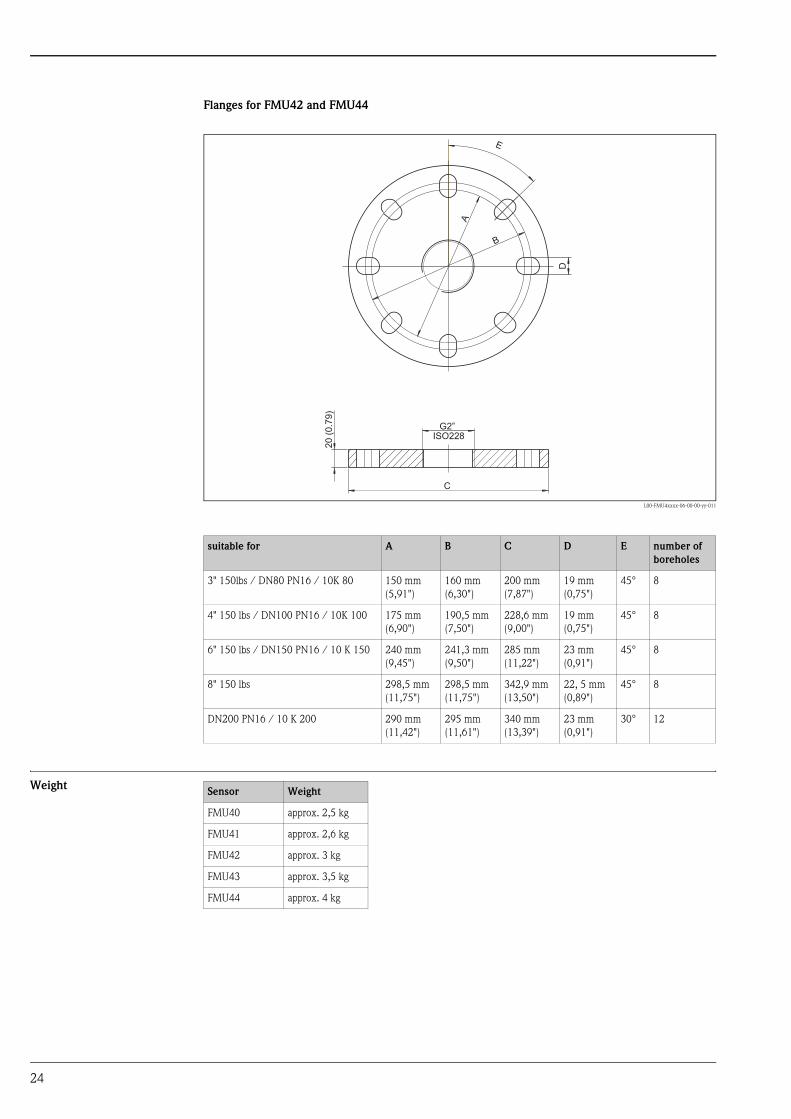
Flanges for FMU42 and FMU44
L00-FMU4xxxx-06-00-00-yy-011
Weight
suitable for A B C D E number of
boreholes
3" 150lbs / DN80 PN16 / 10K 80 150 mm
(5,91")
160 mm
(6,30")
200 mm
(7,87")
19 mm
(0,75")
45° 8
4" 150 lbs / DN100 PN16 / 10K 100 175 mm
(6,90")
190,5 mm
(7,50")
228,6 mm
(9,00")
19 mm
(0,75")
45° 8
6" 150 lbs / DN150 PN16 / 10 K 150 240 mm
(9,45")
241,3 mm
(9,50")
285 mm
(11,22")
23 mm
(0,91")
45° 8
8" 150 lbs 298,5 mm
(11,75")
298,5 mm
(11,75")
342,9 mm
(13,50")
22, 5 mm
(0,89")
45° 8
DN200 PN16 / 10 K 200 290 mm
(11,42")
295 mm
(11,61")
340 mm
(13,39")
23 mm
(0,91")
30° 12
G2”ISO228
20
(0.7
9)
C
E
A
B
D
Sensor Weight
FMU40 approx. 2,5 kg
FMU41 approx. 2,6 kg
FMU42 approx. 3 kg
FMU43 approx. 3,5 kg
FMU44 approx. 4 kg
24

Housing design Types of housings
• F12 housing with sealed terminal compartment for standard or EEx ia applications
• T12 housing with separate terminal compartment and explosionproof encapsulation
Material
Aluminium, seawater resistant, powder-coated
Cover
• Aluminium, for version without on-site display
• Inspection glass for version with on-site display. This version cannot be supplied together with the ATEX II
1/2 D certificate.
Process connection,
sealing material,
sensor material
Sensor Process connection Material in contact with process
FMU40 • Thread G 1½“
• Thread NPT 1½“ - 11.5
Sensor: PVDF
Seal: EPDM
FMU41 • Thread 2"
• Thread NPT 2" - 11,5
Sensor: PVDF
Seal: EPDM
FMU42 • Universal flange
DN 80 PN16 / ANSI 3" 150 lbs / JIS 10K 80
• Universal flange
DN 100 PN16 / ANSI 4" 150 lbs / JIS 10K 100
• Mounting bracket
Sensor: PVDF
Seal: VITON or EPDM
Flange: PP, PVDF or SS 316L (1.4435
or 1.4404)1)
1) Endress+Hauser supplies DIN/EN flanges made of stainless steel AISI 316L with the material number 1.4435 or
1.4404. With regard to their temperature stability properties, the materials 1.4435 and 1.4404 are grouped under
13E0 in EN 1092-1 Tab. 18. The chemical composition of the two materials can be identical.
FMU43 • Universal flange
DN 100 / ANSI 4" / JIS16K100
• Mounting bracket
Sensor: UP and SS 316Ti
Seal: EPDM
Flange: PP or SS 316Ti
FMU44 • Universal flange
DN 100 PN16 / ANSI 4" 150 lbs / JIS 10K 100
• Universal flange
DN 150 PN16 / ANSI 6" 150 lbs / JIS 10K 150
• Universal flange
DN200 PN16 / JIS 10K 200
• Flange ANSI 8" 150 lbs
• Mounting bracket
Sensor PVDF
Seal: VITON or EPDM
Flange: PP, PVDF or SS 316L (1.4435
or 1.4404)1
25
Human interface
Display and operating
elements
The LCD module VU 331 for display and operation is located beneath the housing cover. The measured value
is legible through the glass in the cover. Open the cover to operate the device.
L00-FMxxxxxx-07-00-00-en-001
Function of the keys
Symbol in display
continuous flashing
Meaning Alarm Warning Communication Security Locking
Key(s) Meaning
O or V Navigate upwards in the selection list
Edit numeric value within a function
S or W Navigate downwards in the selection list
Edit numeric value within a function
X or Z Navigate to the left within a function group
F Navigate to the right within a function group, confirmation.
O and For
S and FContrast settings of the LCD
O and S and F
Hardware lock / unlock
After a hardware lock, an operation of the instrument via display or
communication is not possible!
The hardware can only be unlocked via the display. An unlock parameter must
be entered to do so.
ENDRESS + HAUSER
E+–
ENDRESS+HAUSER
MICROPILOT II
ENDRESS+HAUSER
MICROPILOT II
IP 65IP 65
Order Code:Ser.-No.:
Order Code:Ser.-No.:
MessbereichMeasuring range
MessbereichMeasuring rangeU 16...36 V DC
4...20 mA
U 16...36 V DC
4...20 mA
max. 20 m
max. 20 m
Ma
de
inG
erm
an
yM
au
lbu
rgM
ad
ein
Ge
rma
ny
Ma
ulb
urg
T>70°C :
A
t >85°C
T>70°C :
A
t >85°C
LCD(liquid crystal display)
Symbols
3 keys
snap-fit
26

On-site operation Operation with VU 331
The LC-Display VU 331 allows configuration via 3 keys directly at the instrument. All device functions can be
set through a menu system. The menu consists of function groups and functions. Within a function, application
parameters can be read or adjusted. The user is guided through a complete configuration procedure.
L00-FMU4xxxx-07-00-00-en-004
Operation with the handheld terminal DXR 375
On devices with HART communication, you can also access the menu using the handheld terminal DXR 375.
L00-FMU4xxxx-07-00-00-de-005
XX
X
XS
S
OO FF
F
F
HOME
FG00 F000 F001 F002 F003 F004 ...
FG01FG02FG03FG04FG05FG06FG07
...
ENDRESS + HAUSER
E+–
Headline Position indicator
Main value UnitSymbol
Selection list
Function groups -> Functions
Help text
Envelopecurve
1# % &
Copy
G H I
P Q R S
, ( ) ‘
A B C
Paste
PageOn
PageUp
DeleteBksp
Insert
J K L
T U V
_ < >
D E F
Hot Key
+ Hot Key
M N O
W X Y Z
+ * /
4
7
.
2
5
8
0
375FIELD COMMUNICATOR
3
6
9
-
9 6
FMU42: LIC0001ONLINE
1 GROUP SELECT2 PV 8.7 m
HELP SAVE
dsdmdmdf das.asdas faasas la.
PageOn
PageUp
Bksp
Delete
Delete
FMU43: LIC0001ONLINE
1 GROUP SELECTION2 PV 8.7 m
HELP SAVE
dsdmdmdf das.asdas faasas la.
FMU43: LIC0001GROUP SELECTION
HOMESAVE
dsdmdmdf das.asdas faasas la.H
FMRU43: LIC0001
HOMESAVE
dsdmdmdf das.asdas faasas la.H
Bksp
1 BASIC SETUP2 SAFETY SETTINGS
BASIC SETUP
1 MEASURED VALUE
4 PROCESS COND.
5 EMPTY CALIBR.
3 MEDIUM PROPERTY
4 LINEARISATION
5 EXTENDED CALIBR.
3 TEMPERATURE
2 TANK SHAPE
27

Remote operation Operation with ToF Tool
The ToF Tool is a graphical operation software for instruments from Endress+Hauser. It is used to support
commissioning, securing of data, signal analysis and documentation of the instruments. It is compatible with
the following operating systems: WinNT4.0, Win2000 and WinXP.
The ToF Tool supports the following functions:
• Online configuration of transmitters
• Signal analysis via envelope curve
• Linearisation table (graphically supported creation, editing, importing and exporting)
• Loading and saving of instrument data (Upload/Download)
• Documentation of measuring point
! Note!
Further information you may find on the CD-ROM, which is enclosed to the instrument.
Connection options
• HART with Commubox FXA 191 (available as accessory)
• PROFIBUS PA
• Service-interface with adapter FXA 193 (available as accessory)
Menu-guided commissioning:
L00-FMU4xxxx-19-00-00-en-003
28
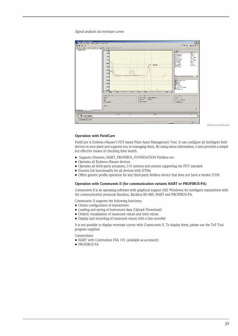
Signal analysis via envelope curve:
L00-FMU4xxxx-19-00-00-en-004
Operation with FieldCare
FieldCare is Endress+Hauser's FDT based Plant Asset Management Tool. It can configure all intelligent field
devices in your plant and supports you in managing them. By using status information, it also provides a simple
but effective means of checking their health.
• Supports Ethernet, HART, PROFIBUS, FOUNDATION Fieldbus etc.
• Operates all Endress+Hauser devices
• Operates all third-party actuators, I/O systems and sensors supporting the FDT standard
• Ensures full functionality for all devices with DTMs
• Offers generic profile operation for any third-party fieldbus device that does not have a vendor DTM
Operation with Commuwin II (for communication variants HART or PROFIBUS-PA)
Commuwin II is an operating software with graphical support (MS Windows) for intelligent transmitters with
the communication protocols Rackbus, Rackbus RS-485, HART and PROFIBUS-PA.
Commuwin II supports the following functions:
• Online configuration of transmitters
• Loading and saving of instrument data (Upload/Download)
• Orderly visualisation of measured values and limit values
• Display and recording of measured values with a line recorder
It is not possible to display envelope curves with Commuwin II. To display them, please use the ToF Tool
program supplied.
Connections:
• HART with Commubox FXA 191 (available as accessory)
• PROFIBUS PA
29

Operation with NI-FBUS Configurator (only Foundation Fieldbus)
The NI-FBUS Configurator is an easy-to-use graphical environment for creating linkages, loops, and a schedule
based on the fieldbus concepts.
You can use the NI-FBUS Configurator to configure a fieldbus network as follows:
• Set block and device tags
• Set device addresses
• Create and edit function block control strategies (function block applications)
• Configure vendor-defined function and transducer blocks
• Create and edit schedules
• Read and write to function block control strategies (function block applications)
• Invoke Device Description (DD) methods
• Display DD menus
• Download a configuration
• Verify a configuration and compare it to a saved configuration
• Monitor a downloaded configuration
• Replace devices
• Save and print a configuration
Certificates and Approvals
CE mark The measuring system meets the legal requirements of the EC-guidelines. Endress+Hauser confirms the
instrument passing the required tests by attaching the CE-mark.
Ex approval The available certificates are listed in the ordering information. Note the associated safety instructions (XA) and
control or installation drawings (ZD).
External standards and
guidelines
EN 60529
Protection class of housing (IP-code)
EN 61326
Electromagnetic compatibility (EMC requirements)
NAMUR
Standards committee for measurement and control in the chemical industry
30
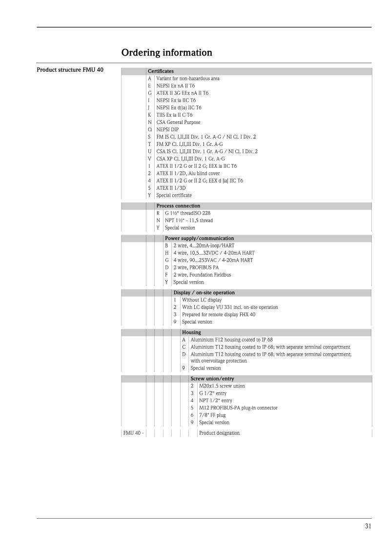
Ordering information
Product structure FMU 40 Certificates
A Variant for non-hazardous area
E NEPSI Ex nA II T6
G ATEX II 3G EEx nA II T6
I NEPSI Ex ia IIC T6
J NEPSI Ex d(ia) IIC T6
K TIIS Ex ia II C T6
N CSA General Purpose
Q NEPSI DIP
S FM IS Cl. I,II,III Div. 1 Gr. A-G / NI Cl. I Div. 2
T FM XP Cl. I,II,III Div. 1 Gr. A-G
U CSA IS Cl. I,II,III Div. 1 Gr. A-G / NI Cl. I Div. 2
V CSA XP Cl. I,II,III Div. 1 Gr. A-G
1 ATEX II 1/2 G or II 2 G; EEX ia IIC T6
2 ATEX II 1/2D, Alu blind cover
4 ATEX II 1/2 G or II 2 G; EEX d [ia] IIC T6
5 ATEX II 1/3D
Y Special certificate
Process connection
R G 1½“ threadISO 228
N NPT 1½“ - 11,5 thread
Y Special version
Power supply/communication
B 2 wire, 4...20mA-loop/HART
H 4 wire, 10,5...32VDC / 4-20mA HART
G 4 wire, 90...253VAC / 4-20mA HART
D 2 wire, PROFIBUS PA
F 2 wire, Foundation Fieldbus
Y Special version
Display / on-site operation
1 Without LC display
2 With LC display VU 331 incl. on-site operation
3 Prepared for remote display FHX 40
9 Special version
Housing
A Aluminium F12 housing coated to IP 68
C Aluminium T12 housing coated to IP 68; with separate terminal compartment
D Aluminium T12 housing coated to IP 68; with separate terminal compartment;
with overvoltage protection
9 Special version
Screw union/entry
2 M20x1.5 screw union
3 G 1/2“ entry
4 NPT 1/2“ entry
5 M12 PROFIBUS-PA plug-in connector
6 7/8" FF plug
9 Special version
FMU 40 - Product designation
31

Product structure FMU 41 Certificates
A Variant for non-hazardous area
E NEPSI Ex nA II T6
G ATEX II 3G EEx nA II T6
I NEPSI Ex ia IIC T6
J NEPSI Ex d(Ia) IIC T6
K TIIS Ex ia II C T6
N CSA General Purpose
Q NEPSI DIP
S FM IS Cl. I,II,III Div. 1 Gr. A-G / NI Cl. I Div. 2
T FM XP Cl. I,II,III Div. 1 Gr. A-G
U CSA IS Cl. I,II,III Div. 1 Gr. A-G / NI Cl. I Div. 2
V CSA XP Cl. I,II,III Div. 1 Gr. A-G
1 ATEX II 1/2 G or II 2 G; EEX ia IIC T6
2 ATEX II 1/2D, Alu blind cover
4 ATEX II 1/2 G or II 2 G; EEX d [ia] IIC T6
5 ATEX II 1/3D
Y Special certificate
Process connection
R G 2“ threadISO 228
N NPT 2“ - 11,5 thread
Y Special version
Power supply/communication
B 2 wire, 4...20mA-loop/HART
H 4 wire, 10,5...32VDC / 4-20mA HART
G 4 wire, 90...253VAC / 4-20mA HART
D 2 wire, PROFIBUS PA
F 2 wire, Foundation Fieldbus
Y Special version
Display / on-site operation
1 Without LC display
2 With LC display VU 331 incl. on-site operation
3 Prepared for remote display FHX 40
9 Special version
Housing
A Aluminium F12 housing coated to IP 68
C Aluminium T12 housing coated to IP 68 with separate terminal compartment
D Aluminium T12 housing coated to IP 68; with separate terminal compartment;
with overvoltage protection
9 Special version
Screw union/entry
2 M20x1.5 screw union
3 G 1/2“ entry
4 NPT 1/2“ entry
5 M12 PROFIBUS-PA plug-in connector
6 7/8" FF plug
9 Special version
FMU 41 - Product designation
32
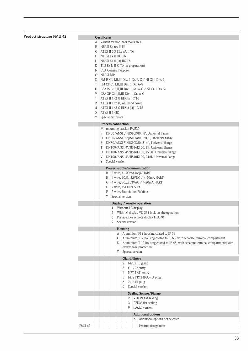
Product structure FMU 42 Certificates
A Variant for non-hazardous area
E NEPSI Ex nA II T6
G ATEX II 3G EEx nA II T6
I NEPSI Ex ia IIC T6
J NEPSI Ex d (Ia) IIC T6
K TIIS Ex ia II C T6 (in preparation)
N CSA General Purpose
Q NEPSI DIP
S FM IS Cl. I,II,III Div. 1 Gr. A-G / NI Cl. I Div. 2
T FM XP Cl. I,II,III Div. 1 Gr. A-G
U CSA IS Cl. I,II,III Div. 1 Gr. A-G / NI Cl. I Div. 2
V CSA XP Cl. I,II,III Div. 1 Gr. A-G
1 ATEX II 1/2 G EEX ia IIC T6
2 ATEX II 1/2 D, Alu bond cover
4 ATEX II 1/2 G EEX d [ia] IIC T6
5 ATEX II 1/3D
Y Special certificate
Process connection
M mounting bracket FAU20
P DN80/ANSI 3"/JIS10K80, PP, Universal flange
Q DN80/ANSI 3"/JIS10K80, PVDF, Universal flange
S DN80/ANSI 3"/JIS10K80, 316L, Universal flange
T DN100/ANSI 4"/JIS16K100, PP, Universal flange
U DN100/ANSI 4"/JIS16K100, PVDF, Universal flange
V DN100/ANSI 4"/JIS16K100, 316L, Universal flange
Y Special version
Power supply/communication
B 2 wire, 4...20mA-loop/HART
H 4 wire, 10,5...32VDC / 4-20mA HART
G 4 wire, 90...253VAC / 4-20mA HART
D 2 wire, PROFIBUS PA
F 2 wire, Foundation Fieldbus
Y Special version
Display / on-site operation
1 Without LC display
2 With LC display VU 331 incl. on-site operation
3 Prepared for remote display FHX 40
9 Special version
Housing
A Aluminium F12 housing coated to IP 68
C Aluminium T12 housing coated to IP 68, with separate terminal compartment
D Aluminium T 12 housing coated to IP 68, with separate terminal compartment; with
overvoltage protection
Y Special version
Gland/Entry
2 M20x1.5 gland
3 G 1/2“ entry
4 NPT 1/2“ entry
5 M12 PROFIBUS-PA plug
6 7/8" FF plug
9 Special version
Sealing Sensor/Flange
2 VITON flat sealing
3 EPDM flat sealing
9 special version
Additional options
A Additional options not selected
FMU 42 - Product designation
33

Product structure FMU 43 Certificates
A Variant for non-hazardous area
M FM DIP Class II, III, Div. 1, Gr. E,F,G NI
N CSA General Purpose
P CSA DIP, Class II, III, Div. 1, Gr. E,F,G NI
Q NEPSI DIP
2 ATEX II 1/2 D or II 2 D, Aluminium Deckel
5 ATEX II 1/3 D or II 3 D, Sichtdeckel
Y Special version
Process connection/material
P Flange DN 100/ANSI 4"/JIS 16K100, PP (universal slip-on flange included)
S Flange DN 100/ANSI 4"/JIS 16K100, SS 316TI (universal slip-on flange included)
K Without slip-on flange/without mounting bracket (customer mounting equipment)
M With mounting bracket
Y Special version
Power supply/communication
H 4 wire, 10,5...32VDC / 4-20mA HART
G 4 wire, 90...253VAC / 4-20mA HART
D 2 wire, PROFIBUS PA
F 2 wire, Foundation Fieldbus
Y Special version
Display / on-site operation
1 Without LC display
2 With LC display VU 331 incl. on-site operation
3 Prepared for remote display FHX 40
9 Special version
Housing
A Aluminium F12 housing coated to IP 68
9 Special version
Screw union/entry
2 M20x1.5 screw union
3 G 1/2“ entry
4 NPT 1/2“ entry
5 M12 PROFIBUS-PA plug-in connector
6 7/8" FF plug
9 Special version
FMU 43 - Product designation
34
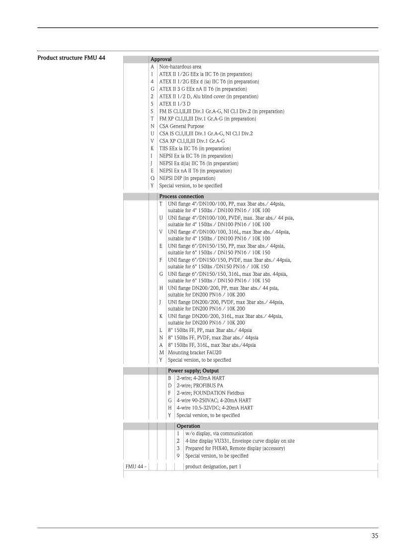
Product structure FMU 44 Approval
A Non-hazardous area
1 ATEX II 1/2G EEx ia IIC T6 (in preparation)
4 ATEX II 1/2G EEx d (ia) IIC T6 (in preparation)
G ATEX II 3 G EEx nA II T6 (in preparation)
2 ATEX II 1/2 D, Alu blind cover (in preparation)
5 ATEX II 1/3 D
S FM IS Cl.I,II,III Div.1 Gr.A-G, NI Cl.I Div.2 (in preparation)
T FM XP Cl.I,II,III Div.1 Gr.A-G (in preparation)
N CSA General Purpose
U CSA IS Cl.I,II,III Div.1 Gr.A-G, NI Cl.I Div.2
V CSA XP Cl.I,II,III Div.1 Gr.A-G
K TIIS EEx ia IIC T6 (in preparation)
I NEPSI Ex ia IIC T6 (in preparation)
J NEPSI Ex d(ia) IIC T6 (in preparation)
E NEPSI Ex nA II T6 (in preparation)
Q NEPSI DIP (in preparation)
Y Special version, to be specified
Process connection
T UNI flange 4"/DN100/100, PP, max 3bar abs./ 44psia,
suitable for 4" 150lbs / DN100 PN16 / 10K 100
U UNI flange 4"/DN100/100, PVDF, max. 3bar abs./ 44 psia,
suitable for 4" 150lbs / DN100 PN16 / 10K 100
V UNI flange 4"/DN100/100, 316L, max 3bar abs./ 44psia,
suitable for 4" 150lbs / DN100 PN16 / 10K 100
E UNI flange 6"/DN150/150, PP, max 3bar abs./ 44psia,
suitable for 6" 150lbs / DN150 PN16 / 10K 150
F UNI flange 6"/DN150/150, PVDF, max 3bar abs./ 44psia,
suitable for 6" 150lbs /DN150 PN16 / 10K 150
G UNI flange 6"/DN150/150, 316L, max 3bar abs. 44psia,
suitable for 6" 150lbs / DN150 PN16 / 10K 150
H UNI flange DN200/200, PP, max 3bar abs./ 44 psia,
suitable for DN200 PN16 / 10K 200
J UNI flange DN200/200, PVDF, max 3bar abs./ 44psia,
suitable for DN200 PN16 / 10K 200
K UNI flange DN200/200, 316L, max 3bar abs./ 44psia,
suitable for DN200 PN16 / 10K 200
L 8" 150lbs FF, PP, max 3bar abs./ 44psia
N 8" 150lbs FF, PVDF, max 2bar abs./ 44psia
A 8" 150lbs FF, 316L, max 3bar abs./44psia
M Mounting bracket FAU20
Y Special version, to be specified
Power supply; Output
B 2-wire; 4-20mA HART
D 2-wire; PROFIBUS PA
F 2-wire; FOUNDATION Fieldbus
G 4-wire 90-250VAC; 4-20mA HART
H 4-wire 10.5-32VDC; 4-20mA HART
Y Special version, to be specified
Operation
1 w/o display, via communication
2 4-line display VU331, Envelope curve display on site
3 Prepared for FHX40, Remote display (accessory)
9 Special version, to be specified
FMU 44 - product designation, part 1
35

Scope of delivery • Instrument according to the version ordered
• "ToF Tool FieldTool Package (2 CD-ROMs: Program CD-ROM, Utility CD-ROM)
• Operating manual according to the communication version
• for certified instrument versions: Safety Instructions, Control- or Installation drawings
• for FMU 40 *R**** and FMU 41 *R****: counter nut (PC)
• for FMU 40/41: sealing ring (EPDM)
• for gland M20x1.5:
– 1 cable gland for 2-wire instruments
– 2 cable glands for 4-wire instruments
The cable glands are mounted on delivery.
Housing
A F12 Alu, coated IP68 NEMA6P
C T12 Alu, coated IP68 NEMA6P, Separate conn. compartment
D T12 Alu, coated IP68 NEMA6P + OVP, Sep. conn. compartment, OVP = overvoltage
protection
9 Special version, to be specified
CAble entry
2 Gland M20 (EEx d > thread M20)
3 Thread G1/2
4 Thread NPT 1/2
5 Plug M12
6 Plug 7/8“
9 Special version, to be specified
Process Sealing Sensor/ Flange
2 Viton
3 EPDM
9 Special version, to be specified
Additional option
A Basic version
Y Special version, to be specified
FMU 44 - complete product designation
36
Accessories
Weather protection cover A Weather protection cover made of stainless steel is recommended for outdoor mounting (order code:
543199-0001). The shipment includes the protective cover and tension clamp.
L00-FMR2xxxx-00-00-06-en-001
Installation bracket for
FMU 40/41
L00-FMU4x-00-00-00-de-001
• for FMU 40, G1½: Order No. 942669-0000
• for FMU 41, G2: Order No. 942669-0001
suited for NPT 1½" and 2" as well
ENDRESS+HAUSER
MICROPILOT II
ENDRESS+HAUSER
MICROPILOT II
IP 65IP 65
Order Code:Ser.-No.:
Order Code:Ser.-No.:
MessbereichMeasuring range
MessbereichMeasuring rangeU 16...36 V DC
4...20 mA
U 16...36 V DC4...20 mA
max. 20 m
max. 20 m
Ma
de
in G
erm
any
Ma
ulb
urg
Ma
de
in G
erm
any
Ma
ulb
urg
T>70°C :
A
t >85°C
T>70°C :
A
t >85°C
70 m
m
240 mm 135 mm
95m
m45°F12 / F23 / T12 housing
400120
120
30
250
A
G
ø16
3
37
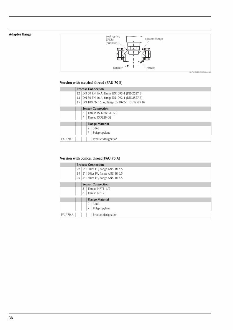
Adapter flange
L00-FMUX3XXX-00-00-00-en-001
Version with metrical thread (FAU 70 E)
Version with conical thread(FAU 70 A)
Process Connection
12 DN 50 PN 16 A, flange EN1092-1 (DIN2527 B)
14 DN 80 PN 16 A, flange EN1092-1 (DIN2527 B)
15 DN 100 PN 16, A, flange EN1092-1 (DIN2527 B)
Sensor Connection
3 Thread ISO228 G1-1/2
4 Thread ISO228 G2
Flange Material
2 316L
7 Polypropylene
FAU 70 E Product designation
Process Connection
22 2" 150lbs FF, flange ANSI B16.5
24 3" 150lbs FF, flange ANSI B16.5
25 4" 150lbs FF, flange ANSI B16.5
Sensor Connection
5 Thread NPT1-1/2
6 Thread NPT2
Flange Material
2 316L
7 Polypropylene
FAU 70 A Product designation
adapter flangesealing ringEPDM(supplied)
sensor nozzle
38

Cantilever
L00-FMU4xxxx-06-00-00-yy-005
• The 50 mm or 62 mm orifices serve for the mounting of the FMU 40 or FMU 41 sensor, respecitvely.
• The 22 mm orifice may be used for an additional sensor.
A B C D for Sensor Material Order Code
585 mm 250 mm 2 mm 200 mm FMU 40 1.4301 (AISI 304) 52014132
galv. steel 52014131
FMU 41 1.4301 (AISI 304) 52014136
galv. steel 52014135
1085 mm 750 mm 3 mm 300 mm FMU 40 1.4301 (AISI 304) 52014134
galv. steel 52014133
FMU 41 1.4301 (AISI 304) 52014138
galv. steel 52014137
A
D M8
35 50
20
2010
5
50/
62 22
C
C
6.5 15
100
25
351007575 B
39
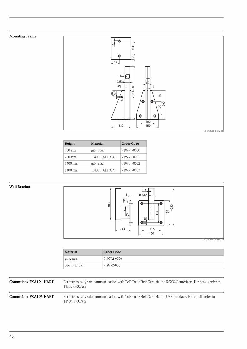
Mounting Frame
L00-FMU4x-00-00-00-yy-005
Wall Bracket
L00-FMU4x-00-00-00-yy-006
Commubox FXA191 HART For intrinsically safe communication with ToF Tool/FieldCare via the RS232C interface. For details refer to
TI237F/00/en.
Commubox FXA195 HART For intrinsically safe communication with ToF Tool/FieldCare via the USB interface. For details refer to
TI404F/00/en.
Height Material Order Code
700 mm galv. steel 919791-0000
700 mm 1.4301 (AISI 304) 919791-0001
1400 mm galv. steel 919791-0002
1400 mm 1.4301 (AISI 304) 919791-0003
3.2
20
55
100
2570
0/14
00
45
7610
0 200
6.5
13
Ø 33.7
130 150100
604
Material Order Code
galv. steel 919792-0000
316Ti/1.4571 919792-0001
110
25
5
6.5
150
ø 33.7
3.2
110
13
150
180
213
88
40
Service Interface FXA193 The Service-Interface connects the Service plug of Proline and ToF instruments with the 9 pin RS 232C
interface of a PC. (USB connectors must be equipped with a usual commercial USB/Serial adapter.)
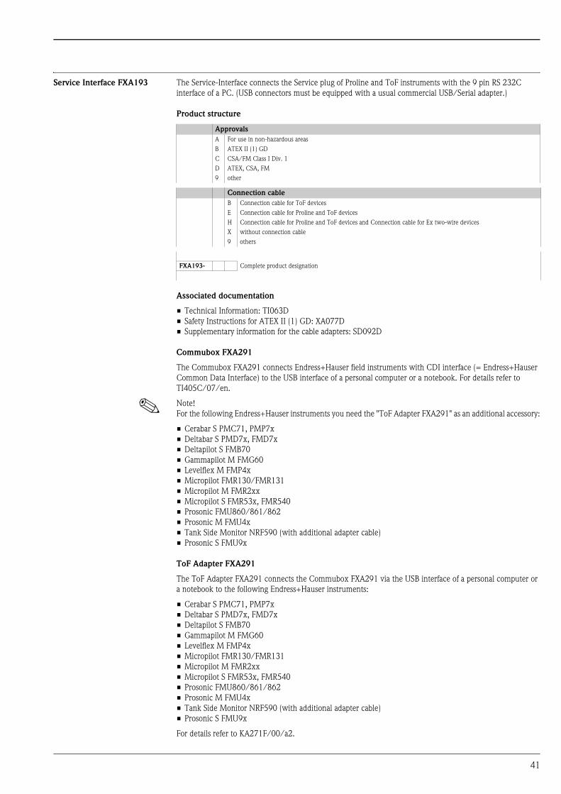
Product structure
Associated documentation
• Technical Information: TI063D
• Safety Instructions for ATEX II (1) GD: XA077D
• Supplementary information for the cable adapters: SD092D
Commubox FXA291
The Commubox FXA291 connects Endress+Hauser field instruments with CDI interface (= Endress+Hauser
Common Data Interface) to the USB interface of a personal computer or a notebook. For details refer to
TI405C/07/en.
! Note!
For the following Endress+Hauser instruments you need the "ToF Adapter FXA291" as an additional accessory:
• Cerabar S PMC71, PMP7x
• Deltabar S PMD7x, FMD7x
• Deltapilot S FMB70
• Gammapilot M FMG60
• Levelflex M FMP4x
• Micropilot FMR130/FMR131
• Micropilot M FMR2xx
• Micropilot S FMR53x, FMR540
• Prosonic FMU860/861/862
• Prosonic M FMU4x
• Tank Side Monitor NRF590 (with additional adapter cable)
• Prosonic S FMU9x
ToF Adapter FXA291
The ToF Adapter FXA291 connects the Commubox FXA291 via the USB interface of a personal computer or
a notebook to the following Endress+Hauser instruments:
• Cerabar S PMC71, PMP7x
• Deltabar S PMD7x, FMD7x
• Deltapilot S FMB70
• Gammapilot M FMG60
• Levelflex M FMP4x
• Micropilot FMR130/FMR131
• Micropilot M FMR2xx
• Micropilot S FMR53x, FMR540
• Prosonic FMU860/861/862
• Prosonic M FMU4x
• Tank Side Monitor NRF590 (with additional adapter cable)
• Prosonic S FMU9x
For details refer to KA271F/00/a2.
Approvals
A For use in non-hazardous areas
B ATEX II (1) GD
C CSA/FM Class I Div. 1
D ATEX, CSA, FM
9 other
Connection cable
B Connection cable for ToF devices
E Connection cable for Proline and ToF devices
H Connection cable for Proline and ToF devices and Connection cable for Ex two-wire devices
X without connection cable
9 others
FXA193- Complete product designation
41

Remote display FHX40
L00-FMxxxxxx-00-00-06-en-003
Technical data (cable and housing) and product structure:
For connection of the remote display FHX40 use the cable which fits the communication version of the
respective instrument.
ENDRESS+HAUSER
ENDRESS+HAUSER
IP 65IP 65
Order Code:Ser.-No.:
Order Code:Ser.-No.:
MessbereichMeasuring range
MessbereichMeasuring rangeU 16...36 V DC
4...20 mA
U 16...36 V DC4...20 mA
max. 20 m
max. 20 m
Made in
Germ
any
M
aulb
urg
Made in
Germ
any
M
aulb
urg
T>70°C :
A
t >85°C
T>70°C :
A
t >85°C 82
6,3
106
122
120
max. 80min. 30
96
88
160
8,5
118
180Micropilot M
Levelflex MProsonic M
Separate housingFHX40 (IP 65)
Cable
122
150
80
Wall-mounting(without mounting bracket)
Pipe-mounting(mounting bracket and plate
supplied optionally,s. product structure)
pipe
Max. cable length 20 m (65 ft)
Temperature range -30 °C...+70 °C (-22 °F...158 °F)
Degree of protection IP65/67 (housing); IP68 (cable) acc. to IEC 60529
Materials Housing: AlSi12; cable glands: nickle plated brass
Dimensions [mm] / [inch] 122x150x80 (HxWxD) / 4.8x5.9x3.2
Approval:
A Nn-hazardous area
1 ATEX II 2 G EEx ia IIC T6, ATEX II 3D
S FM IS Cl.I Div.1 Gr.A-D
U CSA IS Cl.I Div.1 Gr.A-D
N CSA General Purpose
K TIIS ia IIC T6 (in preparation)
Cable:
1 20m/65ft; for HART
5 20m/65ft; for PROFIBUS PA/FOUNDATION Fieldbus
Additional option:
A Basic version
B Mounting bracket, pipe 1"/ 2"
FHX40 - Complete product designation
42
Supplementary documentation
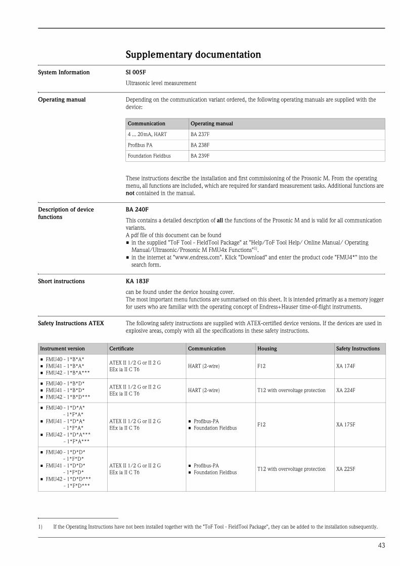
System Information SI 005F
Ultrasonic level measurement
Operating manual Depending on the communication variant ordered, the following operating manuals are supplied with the
device:
These instructions describe the installation and first commissioning of the Prosonic M. From the operating
menu, all functions are included, which are required for standard measurement tasks. Additional functions are
not contained in the manual.
Description of device
functions
BA 240F
This contains a detailed description of all the functions of the Prosonic M and is valid for all communication
variants.
A pdf file of this document can be found
• in the supplied "ToF Tool - FieldTool Package" at "Help/ToF Tool Help/ Online Manual/ Operating
Manual/Ultrasonic/Prosonic M FMU4x Functions"1).
• in the internet at "www.endress.com". Klick "Download" and enter the product code "FMU4*" into the
search form.
Short instructions KA 183F
can be found under the device housing cover.
The most important menu functions are summarised on this sheet. It is intended primarily as a memory jogger
for users who are familiar with the operating concept of Endress+Hauser time-of-flight instruments.
Safety Instructions ATEX The following safety instructions are supplied with ATEX-certified device versions. If the devices are used in
explosive areas, comply with all the specifications in these safety instructions.
Communication Operating manual
4 ... 20mA, HART BA 237F
Profibus PA BA 238F
Foundation Fieldbus BA 239F
1) If the Operating Instructions have not been installed together with the "ToF Tool - FieldTool Package", they can be added to the installation subsequently.
Instrument version Certificate Communication Housing Safety Instructions
• FMU40 - 1*B*A*
• FMU41 - 1*B*A*
• FMU42 - 1*B*A***
ATEX II 1/2 G or II 2 G
EEx ia II C T6HART (2-wire) F12 XA 174F
• FMU40 - 1*B*D*
• FMU41 - 1*B*D*
• FMU42 - 1*B*D***
ATEX II 1/2 G or II 2 G
EEx ia II C T6HART (2-wire) T12 with overvoltage protection XA 224F
• FMU40 - 1*D*A*
- 1*F*A*
• FMU41 - 1*D*A*
- 1*F*A*
• FMU42 - 1*D*A***
- 1*F*A***
ATEX II 1/2 G or II 2 G
EEx ia II C T6
• Profibus-PA
• Foundation FieldbusF12 XA 175F
• FMU40 - 1*D*D*
- 1*F*D*
• FMU41 - 1*D*D*
- 1*F*D*
• FMU42 - 1*D*D***
- 1*F*D***
ATEX II 1/2 G or II 2 G
EEx ia II C T6
• Profibus-PA
• Foundation FieldbusT12 with overvoltage protection XA 225F
43
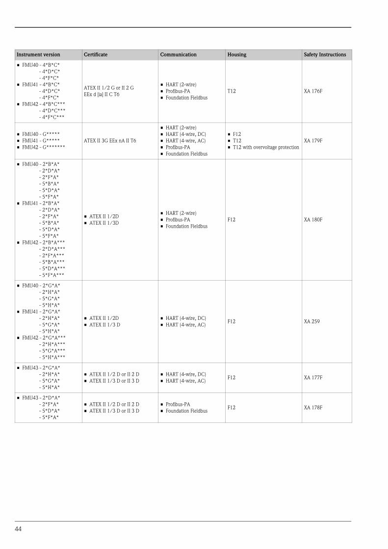
• FMU40 - 4*B*C*
- 4*D*C*
- 4*F*C*
• FMU41 - 4*B*C*
- 4*D*C*
- 4*F*C*
• FMU42 - 4*B*C***
- 4*D*C***
- 4*F*C***
ATEX II 1/2 G or II 2 G
EEx d [ia] II C T6
• HART (2-wire)
• Profibus-PA
• Foundation Fieldbus
T12 XA 176F
• FMU40 - G*****
• FMU41 - G*****
• FMU42 - G*******
ATEX II 3G EEx nA II T6
• HART (2-wire)
• HART (4-wire, DC)
• HART (4-wire, AC)
• Profibus-PA
• Foundation Fieldbus
• F12
• T12
• T12 with overvoltage protection
XA 179F
• FMU40 - 2*B*A*
- 2*D*A*
- 2*F*A*
- 5*B*A*
- 5*D*A*
- 5*F*A*
• FMU41 - 2*B*A*
- 2*D*A*
- 2*F*A*
- 5*B*A*
- 5*D*A*
- 5*F*A*
• FMU42 - 2*B*A***
- 2*D*A***
- 2*F*A***
- 5*B*A***
- 5*D*A***
- 5*F*A***
• ATEX II 1/2D
• ATEX II 1/3D
• HART (2-wire)
• Profibus-PA
• Foundation Fieldbus
F12 XA 180F
• FMU40 - 2*G*A*
- 2*H*A*
- 5*G*A*
- 5*H*A*
• FMU41 - 2*G*A*
- 2*H*A*
- 5*G*A*
- 5*H*A*
• FMU42 - 2*G*A***
- 2*H*A***
- 5*G*A***
- 5*H*A***
• ATEX II 1/2D
• ATEX II 1/3 D
• HART (4-wire, DC)
• HART (4-wire, AC)F12 XA 259
• FMU43 - 2*G*A*
- 2*H*A*
- 5*G*A*
- 5*H*A*
• ATEX II 1/2 D or II 2 D
• ATEX II 1/3 D or II 3 D
• HART (4-wire, DC)
• HART (4-wire, AC)F12 XA 177F
• FMU43 - 2*D*A*
- 2*F*A*
- 5*D*A*
- 5*F*A*
• ATEX II 1/2 D or II 2 D
• ATEX II 1/3 D or II 3 D
• Profibus-PA
• Foundation FieldbusF12 XA 178F
Instrument version Certificate Communication Housing Safety Instructions
44

Safety Instructions NEPSI The following safety instructions are supplied with NEPSI-certified device versions. If the devices are used in
explosive areas, comply with all the specifications in these safety instructions.
Instrument version Certificate Communication Housing Safety Instructions
• FMU40 - I*B*A*
• FMU41 - I*B*A*
• FMU42 - I*B*A***
Ex ia II C T1 ... T6
NEPSI GYJ071468HART (2-wire) F12 XA 436F
• FMU40 - I*B*D*
• FMU41 - I*B*D*
• FMU42 - I*B*D***
Ex ia II C T1 ... T6
NEPSI GYJ071468HART (2-wire) T12 with overvoltage protection XA 442F
• FMU40 - I*D*A*
- I*F*A*
• FMU41 - I*D*A*
- I*F*A*
• FMU42 - I*D*A***
- I*F*A***
Ex ia II C T1 ... T6
NEPSI GYK071468
• Profibus-PA
• Foundation FieldbusF12 XA 437F
• FMU40 - I*D*D*
- I*F*D*
• FMU41 - I*D*D*
- I*F*D*
• FMU42 - I*D*D***
- I*F*D***
Ex ia II C T1 ... T6
NEPSI GYJ071468
• Profibus-PA
• Foundation FieldbusT12 with overvoltage protection XA 443F
• FMU40 - J*B*C*
- J*D*C*
- J*F*C*
• FMU41 - J*B*C*
- J*D*C*
- J*F*C*
• FMU42 - J*B*C***
- J*D*C***
- J*F*C***
Ex d [ia] II C T1 ... T6
NEPSI GYJ071468
• HART (2-wire)
• Profibus-PA
• Foundation Fieldbus
T12 XA 438F
• FMU40 - Q*B*A*
- Q*D*A*
- Q*F*A*
• FMU41 - Q*B*A*
- Q*D*A*
- Q*F*A*
• FMU42 - Q*B*A***
- Q*D*A***
- Q*F*A***
DIP A21/A22 TA, T*
NEPSI GYJ071468
• HART (2-wire)
• Profibus-PA
• Foundation Fieldbus
F12 XA 441F
• FMU40 - Q*G*A*
- Q*H*A*
• FMU41 - Q*G*A*
- Q*H*A*
• FMU42 - Q*G*A***
- Q*H*A***
DIP A21/A22 TA, T*
NEPSI GYJ071468
• HART (4-wire, DC)
• HART (4-wire, AC)F12 XA 444F
• FMU43 - Q*G*A*
- Q*H*A*DIP A21/A22 TA, T*
• HART (4-wire, DC)
• HART (4-wire, AC)F12 XA 439F
• FMU43 - Q*D*A*
- Q*F*A*DIP A21/A22 TA, T*
• Profibus-PA
• Foundation FieldbusF12 XA 440F
• FMU40 - E*****
• FMU41 - E*****
• FMU42 - E*******
NEPSI Ex nA IIC T6
• HART
• Profibus PA
• Foundation Fieldbus
• F12
• T12XA 403F
45

Control drawings Installation
drawings
The following control or installation drawings are supplied with the FM, CSA and TIIS-certified device
versions:
Instrument version Certificate Communication Housing Control or Installation
Drawing
• FMU40 - S*B*A*
• FMU41 - S*B*A*
• FMU42 - S*B*A***
FM IS HART (2-wire) F12 ZD 096F
• FMU40 - S*D*A*
- S*F*A*
• FMU41 - S*D*A*
- S*F*A*
• FMU42 - S*D*A***
- S*F*A***
FM IS• Profibus-PA
• Foundation FieldbusF12 ZD 097F
• FMU40 - S*B*D*
• FMU41 - S*B*D*
• FMU42 - S*B*D***
FM IS HART (2-wire) T12 with overvoltage protection ZD 139F
• FMU40 - S*D* D*
- S*F*D*
• FMU41 - S*D* D*
- S*F*D*
• FMU42 - S*D* D***
- S*F*D***
FM IS• Profibus-PA
• Foundation FieldbusT12 with overvoltage protection ZD 140F
• FMU40 - T*B*C*
- T*D*C*
- T*F*C*
• FMU41 - T*B*C*
- T*D*C*
- T*F*C*
• FMU42 - T*B*C***
- T*D*C***
- T*F*C***
FM XP
• HART (2-wire)
• Profibus PA
• Foundation Fieldbus
T12 ZD 098F
• FMU40 - U*B*A*
• FMU41 - U*B*A*
• FMU42 - U*B*A***
• FMU44 - U*B*A***
CSA IS HART (2-wire) F12 ZD 088F
• FMU40 - U*D*A*
- U*F*A*
• FMU41 - U*D*A*
- U*F*A*
• FMU42 - U*D*A***
- U*F*A***
• FMU44 - U*D*A***
- U*F*A***
CSA IS• Profibus-PA
• Foundation FieldbusF12 ZD 099F
• FMU40 - U*B* D*
• FMU41 - U*B* D*
• FMU42 - U*B* D***
• FMU44 - U*B* D***
CSA IS HART (2-wire) T12 with overvoltage protection ZD 101F
• FMU40 - U*D*D*
- U*F*D*
• FMU41 - U*D*D*
- U*F*D*
• FMU42 - U*D*D***
- U*F*D***
• FMU44 - U*D*D***
- U*F*D***
CSA IS• Profibus-PA
• Foundation FieldbusT12 with overvoltage protection ZD 102F
46
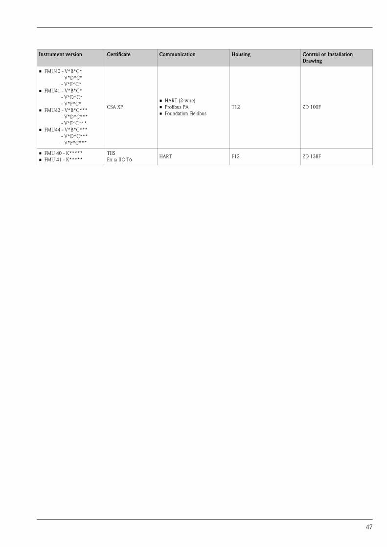
• FMU40 - V*B*C*
- V*D*C*
- V*F*C*
• FMU41 - V*B*C*
- V*D*C*
- V*F*C*
• FMU42 - V*B*C***
- V*D*C***
- V*F*C***
• FMU44 - V*B*C***
- V*D*C***
- V*F*C***
CSA XP
• HART (2-wire)
• Profibus PA
• Foundation Fieldbus
T12 ZD 100F
• FMU 40 - K*****
• FMU 41 - K*****
TIIS
Ex ia IIC T6HART F12 ZD 138F
Instrument version Certificate Communication Housing Control or Installation
Drawing
47

In
EnInKa41Sw
TeFawwinf
struments International
dress+Hauserstruments International AGegenstrasse 253 Reinachitzerland
l. +41 61 715 81 00x +41 61 715 25 00
TI365F/00/en/06.08
FM+SGML 6.0 ProMoDo
Top Related