


Languages
Pages
Legal

Synthetic polymer scaffolds for tissue engineering
Elsie S. Place,ab
Julian H. George,ab
Charlotte K. Williamsc
and Molly M. Stevens*ab
Received 7th July 2008
First published as an Advance Article on the web 16th February 2009
DOI: 10.1039/b811392k
The field of tissue engineering places complex demands on the materials it uses. The materials
chosen to support the intricate processes of tissue development and maintenance need to have
properties which serve both the bulk mechanical and structural requirements of the target tissue,
as well as enabling interactions with cells at the molecular scale. In this critical review we explore
how synthetic polymers can be utilised to meet the needs of tissue engineering applications, and
how biomimetic principles can be applied to polymeric materials in order to enhance the
biological response to scaffolding materials (105 references).
Introduction
Tissue engineering (TE) aims to generate replacement biological
tissues and organs for a wide range of medical conditions
involving tissue loss or dysfunction. The clinical scope of TE is
enormous, with therapeutic potential in many of the ageing
and lifestyle diseases prevalent in Western populations—such
as heart disease, diabetes, cirrhosis and osteoarthritis—as well
as a host of other major afflictions, including spinal cord injury
and disfigurement. TE typically involves implanting cells
into some form of supporting structural device—termed a
scaffold—and allowing the cells to remodel the scaffold into
natural tissue, before implanting it into a patient’s body. In
some cases this middle step can be omitted and the scaffold can
be placed directly into the recipient, utilising a compartment of
the host’s own body as a bioreactor. This raises the possibility
of cell harvest, scaffold seeding and implantation occurring in
a single surgical event. Taking this approach one step further,
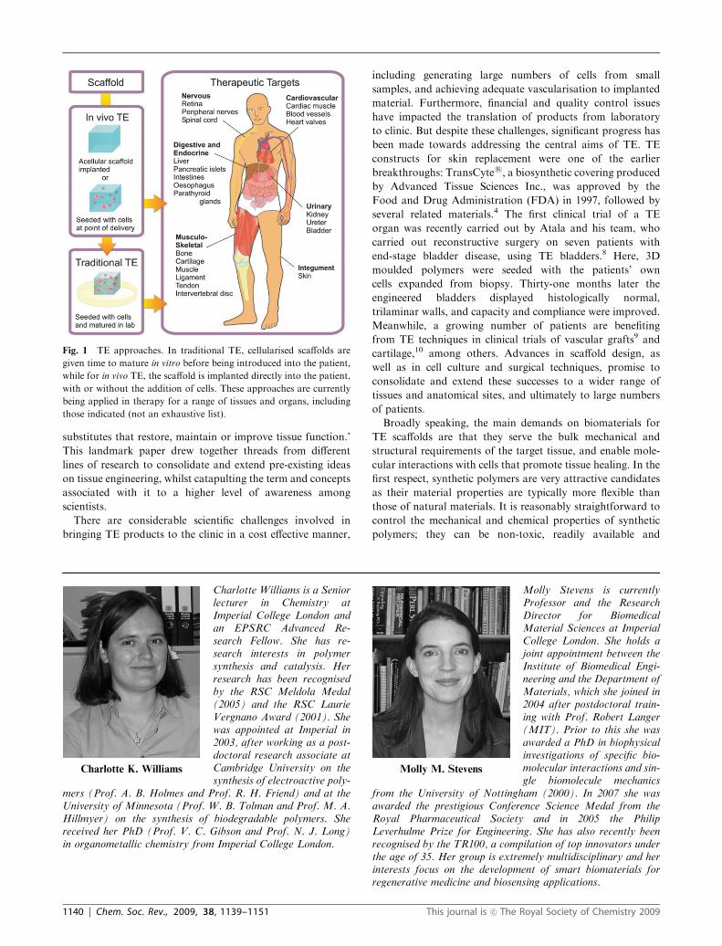
the scaffolding material is sometimes inserted without cells;
regeneration then relies on the recruitment of native cells into
the implant and the subsequent deposition of an extracellular
matrix (ECM) (Fig. 1).1–3 Whichever approach is taken, the
scaffold itself is critical to the success of the implant, and in
many cases actively directs the behaviour of the cells within.
The roots of TE extend at least as far back as the 1970s with
several independent attempts to create skin substitutes using
cultured cell sheets, or collagen and glycosaminoglycans
(natural components of many tissues, including skin).4
However, a shift in emphasis from that of using natural
scaffolds towards the use of synthetic polymers signalled the
genesis of the field as we know it today. Vacanti et al.
experimented with different synthetic degradable polymers to
try to create functional tissue ex vivo,5 and in 1991 the team
implanted the first tissue engineered device to be used in a
human.6 In this procedure a synthetic polymer scaffold, seeded
with the patient’s own cartilage cells, was introduced into a
patient with a congenital sternal deficiency (Poland’s
syndrome). For many scientists, the modern understanding
of the term ‘tissue engineering’ dates back to a 1993 paper by
Langer and Vacanti,7 in which they described TE as ‘an
interdisciplinary field that applies the principles of engineering
and the life sciences toward the development of biological
aDepartment of Materials, Imperial College London, London,UK SW7 2AZ. E-mail: [email protected]
b Institute for Biomedical Engineering, Imperial College London,London, UK SW7 2AZ
cDepartment of Chemistry, Imperial College London, London,UK SW7 2AZ
Elsie S. Place
Elsie Place is working towardsa PhD in biomaterials andtissue engineering under thesupervision of Professor MollyStevens at Imperial CollegeLondon. Her PhD project in-volves tissue engineering withalginate and PEG-based hydro-gels. Previously she gained aBSc in anatomy from BristolUniversity. Following this sheworked in science communica-tion and as an anatomy de-monstrator, before taking upher PhD. She is sponsored byan EPSRC Case Award.
Julian H. George
Julian George studied for hisBSc in artificial intelligenceand computer science atEdinburgh University, andwent on to study for an MScin engineering and physicalscience in medicine. He is cur-rently working towards a PhDin Nanostructured TissueEngineering Scaffolds atImperial College London,supervised by Prof. MollyStevens. He is particularlyinterested by how patterns ofchemistry and topographyinfluence cell behaviour.
This journal is �c The Royal Society of Chemistry 2009 Chem. Soc. Rev., 2009, 38, 1139–1151 | 1139
CRITICAL REVIEW www.rsc.org/csr | Chemical Society Reviews
substitutes that restore, maintain or improve tissue function.’
This landmark paper drew together threads from different
lines of research to consolidate and extend pre-existing ideas
on tissue engineering, whilst catapulting the term and concepts
associated with it to a higher level of awareness among
scientists.
There are considerable scientific challenges involved in
bringing TE products to the clinic in a cost effective manner,
including generating large numbers of cells from small
samples, and achieving adequate vascularisation to implanted
material. Furthermore, financial and quality control issues
have impacted the translation of products from laboratory
to clinic. But despite these challenges, significant progress has
been made towards addressing the central aims of TE. TE
constructs for skin replacement were one of the earlier
breakthroughs: TransCytes, a biosynthetic covering produced
by Advanced Tissue Sciences Inc., was approved by the
Food and Drug Administration (FDA) in 1997, followed by
several related materials.4 The first clinical trial of a TE
organ was recently carried out by Atala and his team, who
carried out reconstructive surgery on seven patients with
end-stage bladder disease, using TE bladders.8 Here, 3D
moulded polymers were seeded with the patients’ own
cells expanded from biopsy. Thirty-one months later the
engineered bladders displayed histologically normal,
trilaminar walls, and capacity and compliance were improved.
Meanwhile, a growing number of patients are benefiting
from TE techniques in clinical trials of vascular grafts9 and
cartilage,10 among others. Advances in scaffold design, as
well as in cell culture and surgical techniques, promise to
consolidate and extend these successes to a wider range of
tissues and anatomical sites, and ultimately to large numbers
of patients.
Broadly speaking, the main demands on biomaterials for
TE scaffolds are that they serve the bulk mechanical and
structural requirements of the target tissue, and enable mole-
cular interactions with cells that promote tissue healing. In the
first respect, synthetic polymers are very attractive candidates
as their material properties are typically more flexible than
those of natural materials. It is reasonably straightforward to
control the mechanical and chemical properties of synthetic
polymers; they can be non-toxic, readily available and
Fig. 1 TE approaches. In traditional TE, cellularised scaffolds are
given time to mature in vitro before being introduced into the patient,
while for in vivo TE, the scaffold is implanted directly into the patient,
with or without the addition of cells. These approaches are currently
being applied in therapy for a range of tissues and organs, including
those indicated (not an exhaustive list).
Charlotte K. Williams
Charlotte Williams is a Seniorlecturer in Chemistry atImperial College London andan EPSRC Advanced Re-search Fellow. She has re-search interests in polymersynthesis and catalysis. Herresearch has been recognisedby the RSC Meldola Medal(2005) and the RSC LaurieVergnano Award (2001). Shewas appointed at Imperial in2003, after working as a post-doctoral research associate atCambridge University on thesynthesis of electroactive poly-
mers (Prof. A. B. Holmes and Prof. R. H. Friend) and at theUniversity of Minnesota (Prof. W. B. Tolman and Prof. M. A.Hillmyer) on the synthesis of biodegradable polymers. Shereceived her PhD (Prof. V. C. Gibson and Prof. N. J. Long)in organometallic chemistry from Imperial College London.
Molly M. Stevens
Molly Stevens is currentlyProfessor and the ResearchDirector for BiomedicalMaterial Sciences at ImperialCollege London. She holds ajoint appointment between theInstitute of Biomedical Engi-neering and the Department ofMaterials, which she joined in2004 after postdoctoral train-ing with Prof. Robert Langer(MIT). Prior to this she wasawarded a PhD in biophysicalinvestigations of specific bio-molecular interactions and sin-gle biomolecule mechanics
from the University of Nottingham (2000). In 2007 she wasawarded the prestigious Conference Science Medal from theRoyal Pharmaceutical Society and in 2005 the PhilipLeverhulme Prize for Engineering. She has also recently beenrecognised by the TR100, a compilation of top innovators underthe age of 35. Her group is extremely multidisciplinary and herinterests focus on the development of smart biomaterials forregenerative medicine and biosensing applications.
1140 | Chem. Soc. Rev., 2009, 38, 1139–1151 This journal is �c The Royal Society of Chemistry 2009
relatively inexpensive to produce, and in many cases can be
processed under mild conditions that are compatible with
cells. For these reasons, they have found widespread applica-
tion in TE, but they lack the biological cues inherent in many
natural materials that can promote desirable cell responses.
This review is concerned with how synthetic polymers can be
chosen and modified to fulfil the essential requirements of TE
scaffolds, concentrating first on the control of material proper-
ties, then on ways in which materials may be functionalised to
enhance biological response.
Synthetic polymers for TE
The first requirement of any biomaterial is biocompatibility.
Several synthetic polymers are already known to be bio-
compatible, are FDA licensed for certain applications within
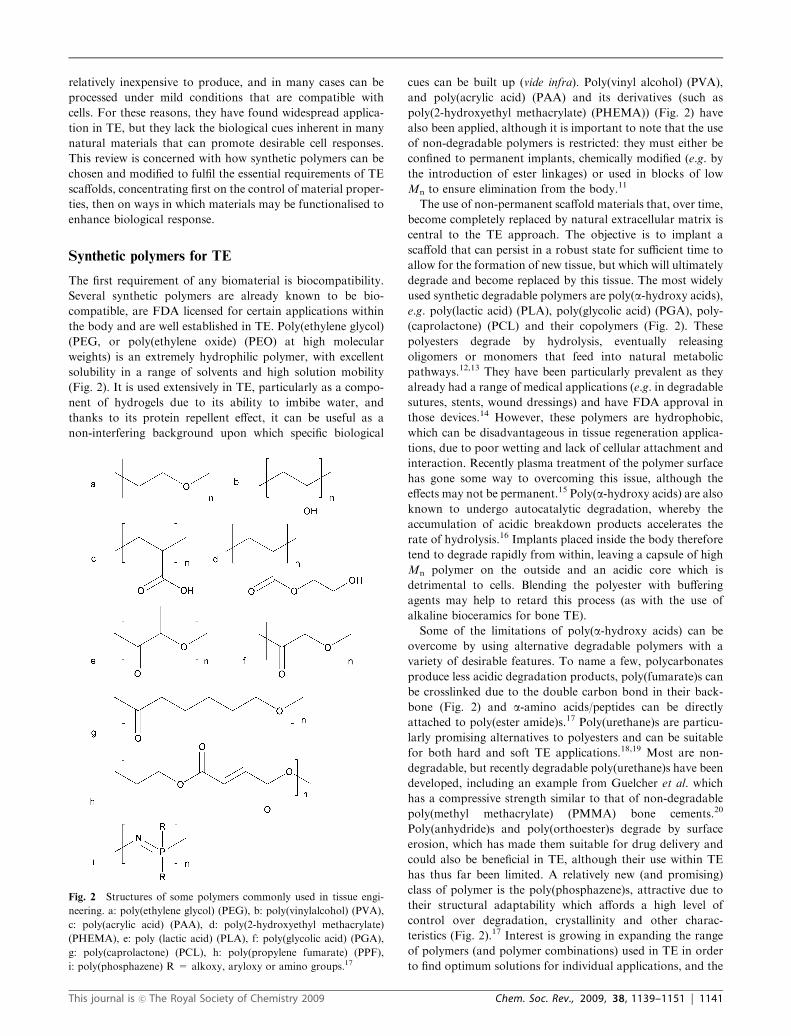
the body and are well established in TE. Poly(ethylene glycol)
(PEG, or poly(ethylene oxide) (PEO) at high molecular
weights) is an extremely hydrophilic polymer, with excellent
solubility in a range of solvents and high solution mobility
(Fig. 2). It is used extensively in TE, particularly as a compo-
nent of hydrogels due to its ability to imbibe water, and
thanks to its protein repellent effect, it can be useful as a
non-interfering background upon which specific biological
cues can be built up (vide infra). Poly(vinyl alcohol) (PVA),
and poly(acrylic acid) (PAA) and its derivatives (such as
poly(2-hydroxyethyl methacrylate) (PHEMA)) (Fig. 2) have
also been applied, although it is important to note that the use
of non-degradable polymers is restricted: they must either be
confined to permanent implants, chemically modified (e.g. by
the introduction of ester linkages) or used in blocks of low
Mn to ensure elimination from the body.11
The use of non-permanent scaffold materials that, over time,
become completely replaced by natural extracellular matrix is
central to the TE approach. The objective is to implant a
scaffold that can persist in a robust state for sufficient time to
allow for the formation of new tissue, but which will ultimately
degrade and become replaced by this tissue. The most widely
used synthetic degradable polymers are poly(a-hydroxy acids),e.g. poly(lactic acid) (PLA), poly(glycolic acid) (PGA), poly-
(caprolactone) (PCL) and their copolymers (Fig. 2). These
polyesters degrade by hydrolysis, eventually releasing
oligomers or monomers that feed into natural metabolic
pathways.12,13 They have been particularly prevalent as they
already had a range of medical applications (e.g. in degradable
sutures, stents, wound dressings) and have FDA approval in
those devices.14 However, these polymers are hydrophobic,
which can be disadvantageous in tissue regeneration applica-
tions, due to poor wetting and lack of cellular attachment and
interaction. Recently plasma treatment of the polymer surface
has gone some way to overcoming this issue, although the
effects may not be permanent.15 Poly(a-hydroxy acids) are alsoknown to undergo autocatalytic degradation, whereby the
accumulation of acidic breakdown products accelerates the
rate of hydrolysis.16 Implants placed inside the body therefore
tend to degrade rapidly from within, leaving a capsule of high
Mn polymer on the outside and an acidic core which is
detrimental to cells. Blending the polyester with buffering
agents may help to retard this process (as with the use of
alkaline bioceramics for bone TE).
Some of the limitations of poly(a-hydroxy acids) can be
overcome by using alternative degradable polymers with a
variety of desirable features. To name a few, polycarbonates
produce less acidic degradation products, poly(fumarate)s can
be crosslinked due to the double carbon bond in their back-
bone (Fig. 2) and a-amino acids/peptides can be directly
attached to poly(ester amide)s.17 Poly(urethane)s are particu-
larly promising alternatives to polyesters and can be suitable
for both hard and soft TE applications.18,19 Most are non-
degradable, but recently degradable poly(urethane)s have been
developed, including an example from Guelcher et al. which
has a compressive strength similar to that of non-degradable
poly(methyl methacrylate) (PMMA) bone cements.20
Poly(anhydride)s and poly(orthoester)s degrade by surface
erosion, which has made them suitable for drug delivery and
could also be beneficial in TE, although their use within TE
has thus far been limited. A relatively new (and promising)
class of polymer is the poly(phosphazene)s, attractive due to
their structural adaptability which affords a high level of
control over degradation, crystallinity and other charac-
teristics (Fig. 2).17 Interest is growing in expanding the range
of polymers (and polymer combinations) used in TE in order
to find optimum solutions for individual applications, and the
Fig. 2 Structures of some polymers commonly used in tissue engi-
neering. a: poly(ethylene glycol) (PEG), b: poly(vinylalcohol) (PVA),
c: poly(acrylic acid) (PAA), d: poly(2-hydroxyethyl methacrylate)
(PHEMA), e: poly (lactic acid) (PLA), f: poly(glycolic acid) (PGA),
g: poly(caprolactone) (PCL), h: poly(propylene fumarate) (PPF),
i: poly(phosphazene) R = alkoxy, aryloxy or amino groups.17
This journal is �c The Royal Society of Chemistry 2009 Chem. Soc. Rev., 2009, 38, 1139–1151 | 1141
development of high-throughput microarrays for screening of
cell–biomaterial interactions could accelerate this process.21
The importance of matching polymers to specific applications
is given further significance by recent results which suggest
that small chemical functional groups may even be used to
influence stem cell differentiation.22
Controlling degradation
The rate of hydrolytic degradation of ester linkages is affected
by a multitude of factors. In general, actions which increase
the penetration of water accelerate the rate of hydrolysis—
such as using, or blending with, a more hydrophilic polymer.
Two important considerations are the polymer’s glass transi-
tion temperature (Tg) and crystallinity, both of which reflect
the ability of water to access the polymer chains. A high Tg
corresponds to relatively limited molecular motion and low
free volume within the polymer network, meaning that less
space is available for water molecules to penetrate. This can be
achieved by stiffening the polymer chain, for example by
incorporating backbone phenol moieties, or bulky side
groups.23 A high degree of crosslinking or chain branching
can also limit movement. Conversely, flexible C–O–C back-
bone linkages increase molecular motion, and the inclusion of
short branches leads to an increase in free volume due to the
higher number of chain ends.23 Both of these factors can
therefore reduce Tg and accelerate hydrolytic degradation.
Similarly, a high degree of crystallinity limits hydration
through the tight, ordered packing of polymer chains. Crystal-
linity is reduced by actions which disrupt packing, such as the
inclusion of short side chains or random copolymerisation,
and is also heavily influenced by polymer stereochemistry.
Poly(L-lactic acid) (PLLA) and poly(D-lactic acid) (PDLA) can
co-crystallise to form a stereocomplex. The polymer chains
form left- and right-handed helices, respectively, and pack
tightly side by side to form a racemic crystal.24,25 This species
shows a higher melting temperature than either of the enan-
tiomers (230 1C compared to 175 1C) and also improved
resistance to hydrolysis.25 Processing conditions can also affect
crystallinity, for example rolling or extrusion can facilitate the
parallel alignment of polymer chains.25 Further influences
include the device size and morphology, and the local pH
conditions.16
A major drawback of random chain hydrolysis is that in
many cases it can lead to a dramatic deterioration in material
strength. One solution is to use scaffolds that undergo con-
trollable degradation, for example where enzyme-cleavable
peptide segments are incorporated into the polymer
network.2,26–29 In living tissues, cells inhabit an extracellular
matrix (ECM) which, although highly tissue specific, consists
largely of soluble and insoluble (mostly fibrous) proteins, and
hydrated polysaccharides. Cells migrate through the matrix
either by adapting their morphology to manoeuvre a path of
least resistance or by clearing a trail using secreted, locally
activated or membrane bound proteases such as matrix
metalloproteases (MMPs) and plasmin.28 This natural process
can be recreated in biomaterials by incorporating matrix
proteins such as collagen or fibrin (which naturally harbour
protease-cleavable sequences), but synthetic systems have also
been designed in which enzyme-cleavable motifs provide this
functionality. West and Hubbell developed ABA copolymers,
consisting of a central poly(ethylene glycol) (PEG) block (B)
with two acrylate end-capped oligopeptides (A) which
included cleavage sites either for MMP-1 (target site APGL)
or for plasmin (target site VRN).29 Photopolymerisation of the
acrylate end groups yielded hydrogels that degraded in the
presence of the targeted protease. Later, a simpler synthetic
strategy was developed whereby a vinyl-sulfate terminated
PEG block was crosslinked with a cysteine-containing peptide
by a Michael-type addition reaction.27 The crosslinking
peptide, GCYKNRCGYKNRCG-NH2, contained three cys-
teine residues and two plasmin substrate sites (shown in bold).
The rate of invasion of cells into this type of hydrogel can be
altered by changing the amino acid sequence, which tunes the
enzymatic sensitivity of the MMP substrate peptide cross-
linkers.26 Lower Mn PEG gives a higher crosslink density
and a finer mesh, which also slows down the movement of
cells into the gels, and at sufficiently high crosslink density it is
possible to exclude cells completely.26
Tissue engineering scaffolds
In addition to the degradation mode and kinetics of the
polymer, the form of the engineered device is critical. Ideally,
damaged tissue should be treated so as to minimise further
injury to the surrounding tissue. One minimally invasive way
to achieve this is to inject a polymer matrix into the site of
damage in the form of a hydrogel—possibly carrying with it
the necessary cells to effect regeneration. Hydrogels are highly
hydrated networks of hydrophilic (often based on PEG or
PAA), crosslinked polymer chains. A gel with covalent cross-
links is known as a chemical hydrogel, commonly produced by
reacting functionalised polymers with small molecule/polymer
crosslinking functionalities, for example, thiols will crosslink
with acrylate or vinyl sulfone groups,27 and amines are used
to crosslink aldehydes or activated ester groups (Fig. 3).30
Crosslinking of acrylate groups can also be achieved
photochemically (i.e. by UV exposure).31
Conversely, physical hydrogels have non-covalent crosslinks,
such as electrostatic interactions, hydrogen bonds or crystal-
lised segments (Fig. 3). Hydrophobic interactions also lead to
gelation, for example by the self-assembly of amphiphilic block
and graft copolymers into micelles, worms or lamellae, followed
by further aggregation and ultimately gelation.32 The exploita-
tion of such physical hydrogels is extended through the use of
biological molecules, species whose structures are typically
enforced by such non-covalent interactions. All the major
classes of biopolymers can be grafted to polymer chains leading
to gelation by a variety of different interactions (Fig. 3).
Examples include complementary oligonucleotide sequences,33
and oppositely charged peptides that dimerise into coiled-coil
superhelices.34 Heparin, an ECM polysaccharide that binds a
multitude of proteins, has been conjugated to PEG by
Yamaguchi and co-workers, and the solution gelled by the
addition of heparin binding growth factor proteins.35
An ideal injectable system would be delivered as a viscous
solution that would mould precisely to fill irregularly shaped
defects before gelling, in situ, under mild conditions. This may
1142 | Chem. Soc. Rev., 2009, 38, 1139–1151 This journal is �c The Royal Society of Chemistry 2009
be achieved—to an extent—by the simultaneous delivery of
reactive precursors from separate syringe barrels. Unfortu-
nately the kinetics of chemical crosslinking can be inappropriate—
either too fast to allow the mixture to flow or slower than
would be convenient in an operating theatre.36 Moreover, cell
surface features may be attacked or become otherwise in-
volved in the reaction. Conversely, by their very nature
physical hydrogels do not have such aggressive reactivity.
Furthermore, they are formed in equilibrium reactions which
can be controlled by the solvent, salt concentration, pH or
temperature. Therefore the careful design of crosslinking
groups can yield materials which gel when introduced to a
physiological environment. Thermally reversible polymers
which undergo sol–gel transitions with increasing temperature
are promising materials in this respect (reviewed recently in
this journal37). Many such materials contain poly(N-isopropyl-
acrylamide) (PNIPAAm); the combination of hydrophilic
amide and hydrophobic isopropyl groups gives it a unique
temperature sensitivity. Below the lower critical solution
temperature, hydrogen bonding between the amide and water
leads to its dissolution, whereas at higher temperatures
polymer–polymer and water–water interactions become domi-
nant and the isopropyl groups dehydrate and aggregate.36 An
alternative approach is to synthesise copolymers from blocks
with different solubilities in aqueous media; using this strategy
PEG is usually coupled to hydrophobic blocks such as
copoly(lactic acid–glycolic acid) (PLGA), PCL or poly(propylene
fumarate) (PPF). The properties of the gels are adjusted
by varying the block length and Mn of the copolymers,
thereby coaxing the sol-to-gel transition temperature into a
physiologically useful range and optimising mechanical
performance.32
In some cases the level of mechanical support required of a
scaffold may exceed that provided by a hydrogel matrix.
Various engineering approaches can be employed in these
instances to produce solid implants that are more resistant
to high forces (Fig. 3). The inclusion of an interconnected
network of pores for cell movement and mass transport of
nutrients is also an essential design feature of these scaffolds.
One method to generate pores is particulate leaching wherein a
polymer melt or solution is poured over a bed of granular
porogens (usually NaCl, sugar or paraffin) which are leached
out once the polymer has solidified.38–40 Foaming techniques
are an alternative, in which gas bubbles are produced by
chemical reaction or the expansion of CO2.18 Supercritical or
high pressure CO2 plasticises the polymer prior to decompres-
sion, so the escape of gas causes the polymer to solidify while
creating porosity. Sintering solid microspheres can also create
solid scaffolds with an open structure. On the other hand,
fibrous scaffolds are produced via electrospinning41 and phase
separation;42 the latter technique can be combined with parti-
culate leaching to produce a macroporous architecture.38
Furthermore, when a thermal gradient is applied during phase
separation, solid walled scaffolds with microtubular architec-
tures are created.43 Teng et al. have used this method to
produce the outer shell of a multicomponent scaffold for
spinal cord repair, the central core of which was produced
by salt leaching. Neural stem cells were introduced into the
inner portion, while the aligned microtubules were intended to
serve as guidance channels for regenerating nerve axons.44
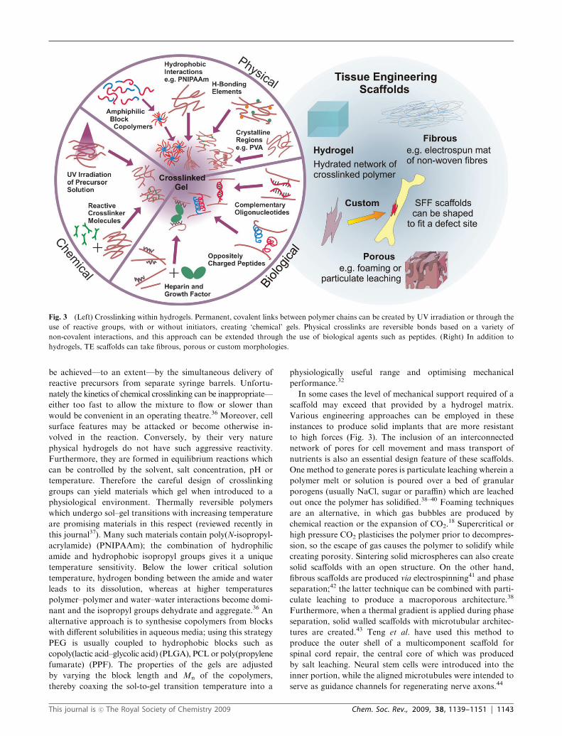
Fig. 3 (Left) Crosslinking within hydrogels. Permanent, covalent links between polymer chains can be created by UV irradiation or through the
use of reactive groups, with or without initiators, creating ‘chemical’ gels. Physical crosslinks are reversible bonds based on a variety of
non-covalent interactions, and this approach can be extended through the use of biological agents such as peptides. (Right) In addition to
hydrogels, TE scaffolds can take fibrous, porous or custom morphologies.
This journal is �c The Royal Society of Chemistry 2009 Chem. Soc. Rev., 2009, 38, 1139–1151 | 1143
Technologically advanced options include a range of
solid freeform fabrication (SFF) techniques. Some of these
are computer assisted systems whereby the layer-by-layer
deposition of materials, including, potentially, cells, into a
pre-specified 3D shape is achieved either through printing or
by the extrusion of a polymer melt. Alternatively laser beams
can be used to solidify polymers into complex shapes by
photopolymerisation or sintering as they sweep over polymer
liquids or layers of powder, respectively.45,46 These technolo-
gies afford precise control over scaffold architectures, and
when coupled to established medical imaging techniques they
can produce solid TE devices fitted to the shape and dimen-
sions of individual defect sites.46 Some of these advanced
options carry a set of more specific material requirements
than the simpler techniques, such as low Tm and high thermal
stability for melt extrusion.47 In some cases the polymer and
manufacturing method are incompatible and this is overcome
by producing negative moulds (i.e. species that can be
dissolved or otherwise removed following casting with the
appropriate polymer).45 The choices, therefore, are broad in
terms of both polymers and fabrication processes: in order to
select method and material from such an array, one needs to
consider the range of properties required of the implant. In
turn, to a large extent these properties are determined by the
tissue which it is intended to replace.
Recreating tissue mechanics
Traditionally, biocompatibility and mechanical properties
have been first considerations in selecting materials for TE
scaffolds, and they remain central to the success of any implant
on several levels. Many of the target tissues for TE exist to
perform an essentially physical task, whether that be as part of
the musculoskeletal, cardiovascular, integumentary or other
system. Artificial constructs which recreate a specific set of
mechanical properties can support the immediate mechanical
needs at the implant site—and one needs only to consider the
example of an engineered heart valve to appreciate how
essential this can be. It is desirable that the physical properties
of a construct resemble those at the implant site as closely as
possible, so that it may tolerate the forces acting on it and
minimise shear by deforming with its surroundings. Addition-
ally, this ought to ensure that appropriate physical stresses and
strains are transmitted to the cells within, for whom such
stimuli may be a profound determinant of their physiological
function.48 However, the mechanics of living tissues are the
product of a whole array of matrix components—their struc-
tures, abundance, organisation and interplay—and working to
the complex mechanical specifications laid down by nature
with our current toolkit is challenging.
In some cases the best way to recreate these properties may
be to perform in vitro conditioning, in which some aspect of
the in vivo mechanical environment is simulated, prompting
cells to deposit an ordered matrix (a promising approach for
TE heart valves, for example49). Often, however, the material
itself may be optimised to possess mechanical properties
approximating those of the target tissue. Each tissue presents
its own set of demands: cortical bone, for example, is notable
for its high strength and toughness while constructs for soft
tissues such as muscle or skin need to be flexible and elastic.
Furthermore, most tissues exhibit anisotropy in their
mechanical properties. The tensile properties of tendons, for
example, are enormously stronger in the direction of force
transmission than they are perpendicular to it, thanks to the
axial alignment of collagen fibres. This parallel arrangement
can be mimicked in electrospun scaffolds by replacing a flat
collecting plate with a rotating collector, the speed of which
determines the degree of fibre alignment.50 Alternatively a
mat of randomly oriented fibres can be annealed at high
temperatures under strain.
Hydrogels have potential in many soft tissue applications
due to their high water content. To produce mechanical
properties suitable for soft tissues, the extent of crosslinking
needs to be controlled: too many crosslinks leads to a brittle
structure and limits swelling; too few produces a material that
is too weak to provide the necessary support. At the optimum
range, a hydrogel will be both strong and elastic. PVA hydro-
gels crosslinked by thermal cycling are unusual in that their
stress–strain relationships display an exponential shape similar
to that of many natural tissues.51 Their physical crosslinks
consist of crystallites which form and grow during each
thermal cycle, resulting, in effect, in a nanocomposite in which
the crystalline regions reinforce an amorphous matrix.
By stretching the sample after a single cycle the primary
crystallites, which have dimensions of just a few nanometres,
can be made to align along the direction of stress, and further
cycling leads to their growth. Increasing the initial strain
applied to the gel leads to a higher degree of crystallite
alignment and therefore anisotropy, whereas the stiffness in
both directions increases in proportion to the number of
thermal cycles as the volume fraction of crystallites continues
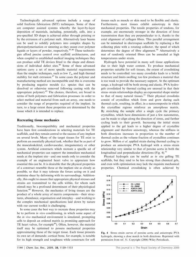
to grow. Millon et al. applied strain during thermal cycling to
produce an anisotropic PVA hydrogel with a stress–strain
relationship very similar to that of porcine aorta in both the
longitudinal and perpendicular directions (Fig. 4).51
Physical hydrogels can be useful as in situ gelling TE
scaffolds, but they tend to be less strong than chemical gels,
and even with optimisation may lack the requisite mechanical
properties. Chemical crosslinking is often achieved by
Fig. 4 Stress–strain curves of porcine aorta and anisotropic PVA
hydrogels, showing a close match in both directions. Reprinted with
permission from ref. 51. Copyright (2006) Wiley Periodicals.
1144 | Chem. Soc. Rev., 2009, 38, 1139–1151 This journal is �c The Royal Society of Chemistry 2009
photopolymerisation of acrylate functionalities; however, the
photoinitiator toxicity and heat effects (when rapid gelation is
required) are not ideal for in vivo use.31 To overcome these
limitations, some groups have introduced both chemical and
physical crosslinks, in a way that improves both the strength
of the hydrogel and the reaction conditions, allowing for rapid
gelation by physical means followed by slow chemical
curing.36 Hiemstra et al. have described a system wherein
stereocomplexation (physical) and photopolymerisation
(chemical) are combined in PLA hydrogels. They used eight-
arm star block copoly(ethylene glycol-D-lactic acid) and
copoly(ethylene glycol-L-lactic acid) with methacrylate end
groups. The poly(D-lactic acid) and poly(L-lactic acid) portions
formed the stereocomplex (vide supra) which itself assisted the
photopolymerisation process. This was apparently due to
the accumulation of the hydrophobic photoinitiator within
the stereocomplex, which permitted the use of a low concen-
tration of photoinitiator.31 The storage moduli of the resulting
‘stereo-photohydrogels’ was drastically increased compared to
equivalent hydrogels formed solely by stereocomplexation
or photopolymerisation—31.6 kPa versus 5.6 and 1.8 kPa,
respectively, in one instance.
To achieve the high strength required for bone TE, compo-
site materials comprising synthetic polymers (usually PLA,
PGA, PCL or crosslinked PPF) and well dispersed reinforcing
particles have been applied. If nanofillers are used, rather than
conventional microscopic or macroscopic additives, the
strengthening effect may be greater still.52 Nanoparticles
introduced directly into a polymer solution will usually pre-
cipitate or phase separate due to weak interfacial bonding, but
a surfactant can aid dispersion. Furthermore, the particles
may be functionalised to enable covalent linkage to the poly-
mer network.53 Large scale improvements in mechanical
properties have been achieved by the addition of small quan-
tities of reinforcing material. Recently, Shi et al. supplemented
PPF with 0.1% wt functionalised single-walled carbon nano-
tubes (SWNTs) to yield a nanocomposite that was over twice
as strong in compression and flexion as pure PPF.54 It was
proposed that covalent linkages formed between the polymer
and nanotubes and improved the mechanical coupling
between the two phases. However, the strength of this type
of composite material still falls far short of the strength and
toughness of bone.
More generally, ceramic or glass particles have been used as
reinforcement materials. The resulting composites are some-
what reminiscent of natural bone matrix, which consists
primarily of hydroxyapatite nano-crystals deposited in bet-
ween highly ordered collagen-I fibres; these two components
render the tissue resistant to compressive and tensile forces,
respectively. Furthermore, crosslinks based on electrostatic
interactions between negatively charged proteins and the
apatite crystals bind the fibres into a strong network. Sarvestani
et al. prepared a peptide of six glutamic acid repeat units to
mimic a glutamic acid rich region in osteonectin (a protein
which binds to both hydroxyapatite and collagen with high
affinity). An acrylate end group was used to covalently attach
the synthetic peptide to a block copoly(lactic acid–fumarate–
ethylene glycol) hydrogel, approximately doubling the shear
modulus of composites produced with nanoapatite crystals.52
Such hydrogel based composites are at an early stage of
development, and their stiffness remains orders of magnitude
below the physiological range, but the strategy of attempting
to model natural structures may prove worthwhile.
Modern TE materials increasingly try to incorporate design
motifs from nature. Anionic proteins such as osteonectin are
implicated in the early stages of bone mineralisation and are
proposed to stabilise the amorphous calcium phosphates,55,56
prompting the use of anionic groups in polymers to improve
mineral growth. Carboxylic acid functional groups can be
incorporated via the use of functionalised monomers,55,57 by
surface modification,58 or they may be generated during ester
hydrolysis.55 Many phosphorus-containing polymers are
also effective at encouraging mineral deposition.56 Wang
et al. describe a photo-crosslinked hydrogel prepared from
poly(ethylene glycol)-di-(ethylphosphatidyl(ethylene glycol)-
methacrylate) and poly(ethylene oxide) diacrylate.59
Osteoblasts (bone forming cells) within the scaffold produce
alkaline phosphatase, an enzyme which cleaves the phospho-
ester linkages in the polymer, releasing phosphoric acid. This
promotes mineralisation as the phosphoric acid reacts with
calcium in the medium to form insoluble calcium phosphate.
Guiding cell behaviour
The impetus to develop composites containing glasses and
ceramics has been driven by more than just their improved
strength. Bioactive glasses (Fig. 5) have the advantage of
chemically bonding to host bone due to the formation of a
carbonated hydroxyapatite surface layer under physiological
conditions.16,60,61 Furthermore, some calcium phosphates
(the class of material to which bone mineral belongs) may possess
osteoinductive potential, i.e. promote the differentiation of
progenitor cells towards an osteoblastic type.62 This is perhaps
not surprising, as the highly complex structures of extra-
cellular matrices have evolved to support many different
requirements, including providing behavioural signals for the
cells that inhabit them, as well as providing structural support.
Accordingly, TE scaffolds are being viewed less and less as
passive cell carriers, and increasingly as structures that can be
loaded with information to direct cell function. Cell behaviour
is guided by a wealth of external influences including ions,
soluble growth factors, ECM elements and the physical
properties of the matrix. Just understanding these interactions
in all their complexity is a monumental challenge for cell
biologists, and recreating them would be an impossible task.
However, it is possible to select certain critical influences and
present them to cells in order to attempt to control behaviour.
Physiology and stem cell research have yielded a wide inven-
tory of molecules that can help to direct cells within TE
scaffolds via specific receptor–ligand interactions. In native
tissues cells attach to substrates by the coupling of binding
domains within matrix proteins, such as fibronectin and
collagen, to integrin receptors on the cell membrane. This
allows force generation for movement, provides behavioural
cues, and without it a cell may undergo apoptosis resulting
from a dearth of cell-matrix signals. Therefore, the incorpora-
tion of adhesion proteins into a scaffold can support the
migration, proliferation, differentiation and even the survival
This journal is �c The Royal Society of Chemistry 2009 Chem. Soc. Rev., 2009, 38, 1139–1151 | 1145
of its cell population. Meanwhile, growth factors are extremely
powerful tools for controlling cell differentiation and function.
Their potency is such that they need only be used in very small
quantities; the technical challenge is to present them in a
functional state over an extended period of time.
Bulk modification with bioactive compounds
The bulk incorporation of proteins into polymer scaffolds is
often achieved simply by mixing the two solutions before
processing.63,64 A variation on this approach is to allow
proteins to diffuse through a hydrogel from one end before
crosslinking, resulting in a concentration gradient that may
provide cells with directional cues.65 Alternatively, polymer
terminal or side groups can be functionalised to enable graft-
ing of biochemicals.66 In some cases proteins or peptides
can be directly incorporated into the polymer backbone,
for example in poly(amido-amines), which are formed by
polyaddition between primary or secondary amines and bis-
acrylamides (Fig. 6).67 Whichever of these approaches is
taken, any processing steps performed after the addition of
protein must allow for these sensitive molecules’ need for mild
conditions.
Where retarded release of growth factor protein is required,
strategies include coating loaded fibres with another polymer,
for example by using chemical vapour deposition.64 Another
way of achieving coated fibres is by co-electrospinning—a new
variation on the electrospinning technique which produces
core–shell fibres in a one-step process.68 A popular technique
is to fabricate loaded microspheres using the double emulsion
technique, whereby primary (water in oil) and secondary
(oil in water) emulsions generate aqueous pockets of dissolved
proteins within polymer droplets.69 The droplets can then be
dried into beads, which can be seeded within a scaffold,40,63
or else an entire scaffold can be fabricated by their fusion
(microsphere sintering). As the microspheres degrade, so the
pockets of dissolved growth factor are gradually freed.
Furthermore, by combining approaches, the sequential release
of two or more growth factors may be contrived in order to
expose cells to a temporal scheme of events designed to
recreate some aspects of developmental pathways.63
Growth factor presentation has been taken to new levels of
sophistication by research teams who have engineered hydro-
gels that permit active, i.e. cell mediated, release of morpho-
genetic signals. Domains for matrix binding and/or cleavage
by proteases are embedded within the structures of many
growth factors, providing ‘off the shelf’ binding and release
activity. Heparin, for example, sequesters numerous morpho-
gens into the matrix by binding them with high affinity until
they are liberated by cellular remodelling. Pratt et al. have
exploited this natural system by attaching peptides with a
heparin binding domain to PEG within hydrogels.27 The
peptide associates with heparin via electrostatic interactions,
and the bound heparin acts as a bridge between the scaffold
and the growth factor (Fig. 7). Thus, a range of different
growth factors can be indirectly tethered to the polymer
matrix. Once immobilised, the growth factor can be released
through the breakdown of heparin by cell-derived enzymes. In
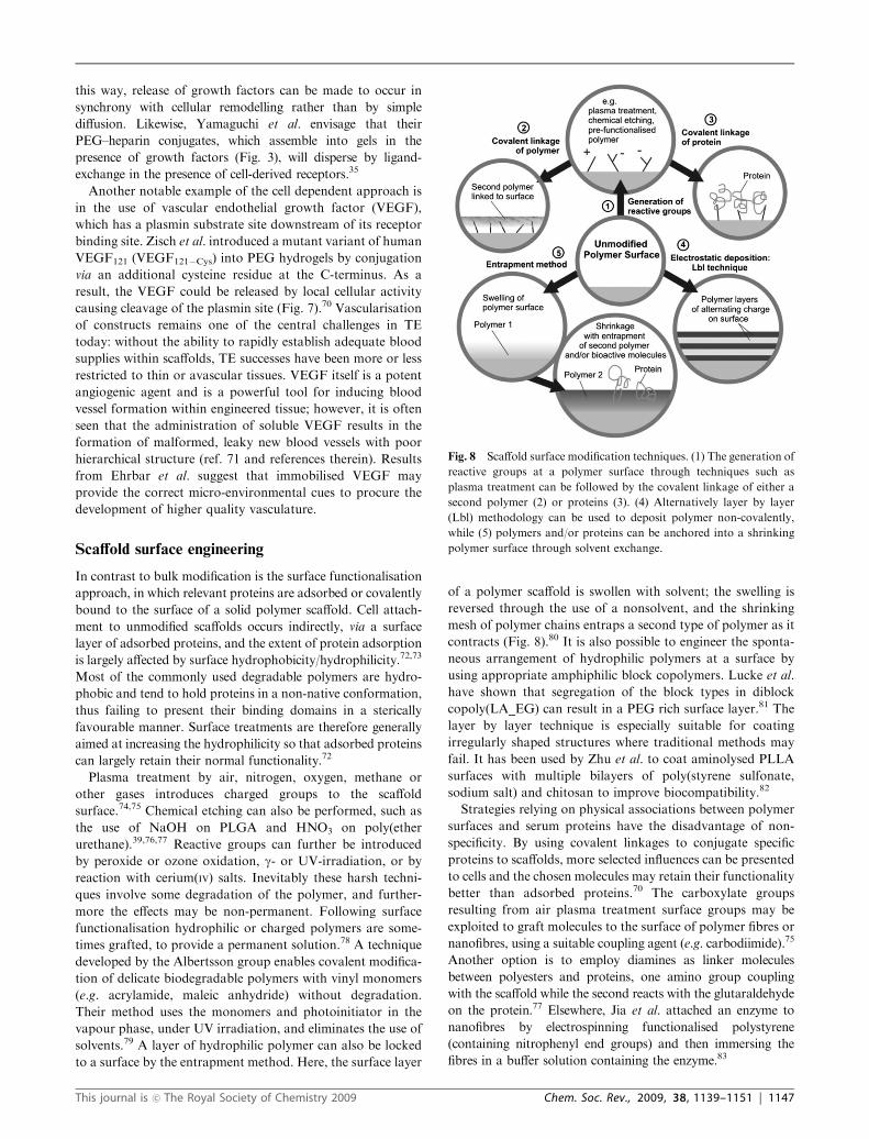
Fig. 6 Bulk modification of polymers. Proteins (or peptides) can be
incorporated into polymer scaffolds by mixing of solutions before
processing; by direct conjugation of protein to polymer chains; by the
addition of protein prior to polymerisation; or by association with
covalently linked protein binding groups.
Fig. 7 (Left) General scheme used by Pratt et al.27 to immobilise
growth factors within hydrogels via a heparin bridge. The growth
factor can be released through polymer or heparin degradation, or in
some cases by cleavage of protease sites within the growth factor.
(Right) Zisch et al.70 conjugated modified VEGF121 to PEG. The
VEGF could be released through plasmin cleavage at amino acid 110.
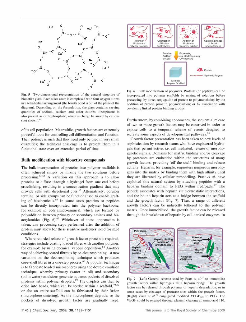
Fig. 5 Two-dimensional representation of the general structure of
bioactive glass. Each silica atom is complexed with four oxygen atoms
in a tetrahedral arrangement (the fourth bond is out of the plane of the
diagram). Depending on the formulation, the glass contains varying
quantities of sodium, calcium and other cations. Phosphorus is
also present as orthophosphate, which is charge balanced by cations
(not shown).61
1146 | Chem. Soc. Rev., 2009, 38, 1139–1151 This journal is �c The Royal Society of Chemistry 2009
this way, release of growth factors can be made to occur in
synchrony with cellular remodelling rather than by simple
diffusion. Likewise, Yamaguchi et al. envisage that their
PEG–heparin conjugates, which assemble into gels in the
presence of growth factors (Fig. 3), will disperse by ligand-
exchange in the presence of cell-derived receptors.35
Another notable example of the cell dependent approach is
in the use of vascular endothelial growth factor (VEGF),
which has a plasmin substrate site downstream of its receptor
binding site. Zisch et al. introduced a mutant variant of human
VEGF121 (VEGF121�Cys) into PEG hydrogels by conjugation
via an additional cysteine residue at the C-terminus. As a
result, the VEGF could be released by local cellular activity
causing cleavage of the plasmin site (Fig. 7).70 Vascularisation
of constructs remains one of the central challenges in TE
today: without the ability to rapidly establish adequate blood
supplies within scaffolds, TE successes have been more or less
restricted to thin or avascular tissues. VEGF itself is a potent
angiogenic agent and is a powerful tool for inducing blood
vessel formation within engineered tissue; however, it is often
seen that the administration of soluble VEGF results in the
formation of malformed, leaky new blood vessels with poor
hierarchical structure (ref. 71 and references therein). Results
from Ehrbar et al. suggest that immobilised VEGF may
provide the correct micro-environmental cues to procure the
development of higher quality vasculature.
Scaffold surface engineering
In contrast to bulk modification is the surface functionalisation
approach, in which relevant proteins are adsorbed or covalently
bound to the surface of a solid polymer scaffold. Cell attach-
ment to unmodified scaffolds occurs indirectly, via a surface
layer of adsorbed proteins, and the extent of protein adsorption
is largely affected by surface hydrophobicity/hydrophilicity.72,73
Most of the commonly used degradable polymers are hydro-
phobic and tend to hold proteins in a non-native conformation,
thus failing to present their binding domains in a sterically
favourable manner. Surface treatments are therefore generally
aimed at increasing the hydrophilicity so that adsorbed proteins
can largely retain their normal functionality.72
Plasma treatment by air, nitrogen, oxygen, methane or
other gases introduces charged groups to the scaffold
surface.74,75 Chemical etching can also be performed, such as
the use of NaOH on PLGA and HNO3 on poly(ether
urethane).39,76,77 Reactive groups can further be introduced
by peroxide or ozone oxidation, g- or UV-irradiation, or by
reaction with cerium(IV) salts. Inevitably these harsh techni-
ques involve some degradation of the polymer, and further-
more the effects may be non-permanent. Following surface
functionalisation hydrophilic or charged polymers are some-
times grafted, to provide a permanent solution.78 A technique
developed by the Albertsson group enables covalent modifica-
tion of delicate biodegradable polymers with vinyl monomers
(e.g. acrylamide, maleic anhydride) without degradation.
Their method uses the monomers and photoinitiator in the
vapour phase, under UV irradiation, and eliminates the use of
solvents.79 A layer of hydrophilic polymer can also be locked
to a surface by the entrapment method. Here, the surface layer
of a polymer scaffold is swollen with solvent; the swelling is
reversed through the use of a nonsolvent, and the shrinking
mesh of polymer chains entraps a second type of polymer as it
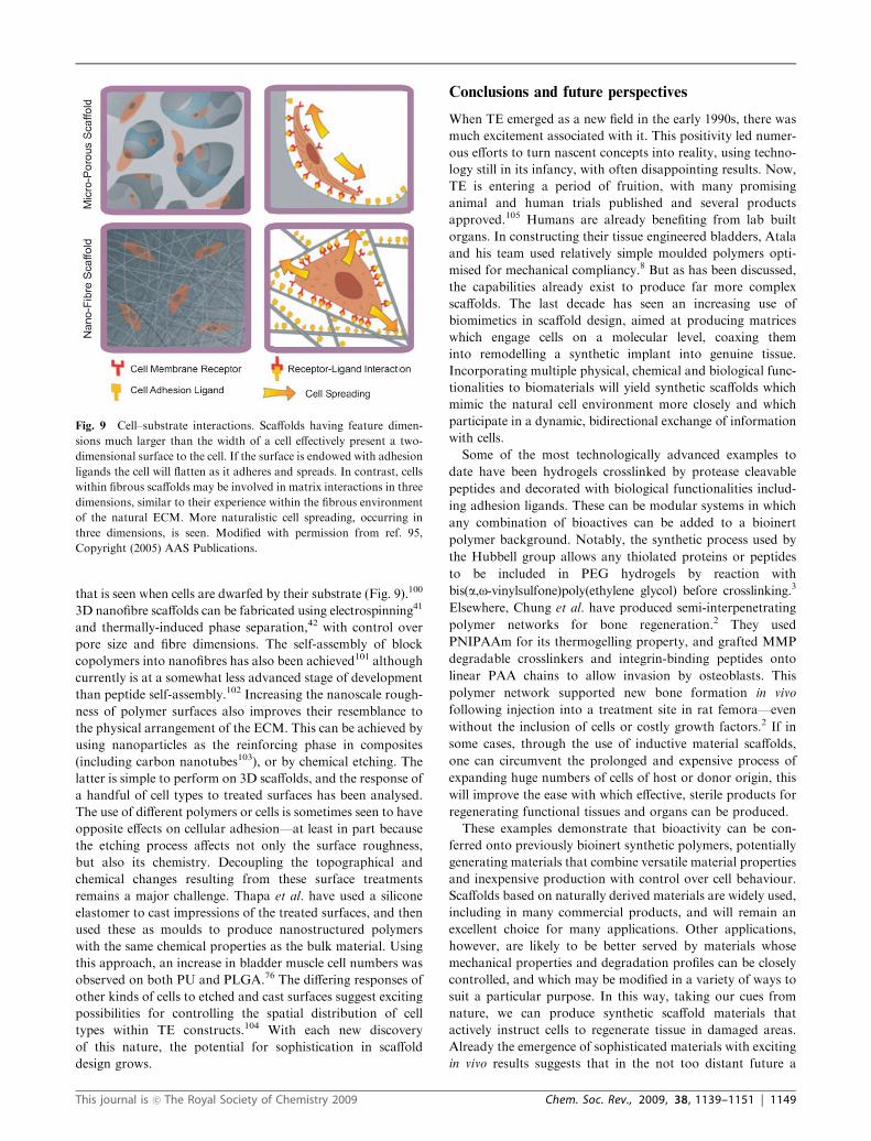
contracts (Fig. 8).80 It is also possible to engineer the sponta-
neous arrangement of hydrophilic polymers at a surface by
using appropriate amphiphilic block copolymers. Lucke et al.
have shown that segregation of the block types in diblock
copoly(LA_EG) can result in a PEG rich surface layer.81 The
layer by layer technique is especially suitable for coating
irregularly shaped structures where traditional methods may
fail. It has been used by Zhu et al. to coat aminolysed PLLA
surfaces with multiple bilayers of poly(styrene sulfonate,
sodium salt) and chitosan to improve biocompatibility.82
Strategies relying on physical associations between polymer
surfaces and serum proteins have the disadvantage of non-
specificity. By using covalent linkages to conjugate specific
proteins to scaffolds, more selected influences can be presented
to cells and the chosen molecules may retain their functionality
better than adsorbed proteins.70 The carboxylate groups
resulting from air plasma treatment surface groups may be
exploited to graft molecules to the surface of polymer fibres or
nanofibres, using a suitable coupling agent (e.g. carbodiimide).75
Another option is to employ diamines as linker molecules
between polyesters and proteins, one amino group coupling
with the scaffold while the second reacts with the glutaraldehyde
on the protein.77 Elsewhere, Jia et al. attached an enzyme to
nanofibres by electrospinning functionalised polystyrene
(containing nitrophenyl end groups) and then immersing the
fibres in a buffer solution containing the enzyme.83
Fig. 8 Scaffold surface modification techniques. (1) The generation of
reactive groups at a polymer surface through techniques such as
plasma treatment can be followed by the covalent linkage of either a
second polymer (2) or proteins (3). (4) Alternatively layer by layer
(Lbl) methodology can be used to deposit polymer non-covalently,
while (5) polymers and/or proteins can be anchored into a shrinking
polymer surface through solvent exchange.
This journal is �c The Royal Society of Chemistry 2009 Chem. Soc. Rev., 2009, 38, 1139–1151 | 1147

Use of peptides in polymer scaffolds
Adding full proteins to biomaterials can be difficult to execute
as the proteins are vulnerable to denaturation and degrada-
tion. A widely used method to improve cell adhesion is to
incorporate short peptide motifs derived from binding regions
of ECM proteins. Although they may only have a fraction of
the activity of the complete protein, they can be included at
very high concentration and are easy to synthesise and func-
tionalise. Furthermore, when used in combination with PEG,
non-specific protein adsorption can be eliminated and upon
this blank canvas only the desired, specific receptor-mediated
interactions will occur.
The well-known Arg-Gly-Asp (RGD) motif from various
ECM proteins including fibronectin, laminin, collagen I,
fibrinogen and vitronectin was being investigated as a means
of improving cell adhesion to surfaces as far back as the late
1980s.84 It has since been incorporated into a wide range of
surfaces, scaffolds and hydrogels. The binding specificity of the
peptide to cell surface integrin receptors can be improved by
using a cyclic peptide conformation, and the flanking peptides
are also critical: GRGDS is the most commonly used.85 The
inclusion of a PEG spacer arm may improve cellular response
to RGD in terms of both magnitude and specificity by
suppressing protein adsorption and presenting the motif to
cells in a sterically favourable fashion.86 A biphasic cell
response is noted with varying RGD concentrations:
maximum cell migration is seen at intermediate ligand densi-
ties, because too few attachment sites fail to adequately
support contractile forces, and high concentrations overwhelm
the cells’ ability to detach from the substrate.28 Massia et al.
determined that an average distance of 440 nm between RGD
peptides was sufficient to enable fibroblast attachment and
spreading, but a significantly higher density—an interpeptide
distance of 140 nm—was required for focal contact formation
and cytoskeletal reorganisation into stress fibres.87
Although RGD peptides have been extensively used, other
adhesion sequences have been studied too including IKLLI,
IKVAV, LRE, PDSGR and YIGSR from laminin, DGEA
from collagen I and GEFYFDLRLKGDK from collagen IV,
and also cell-adhesive carbohydrates.88–90 A Pro-His-Ser-Arg-Asn
(PHSRN) sequence also found in fibronectin enhances
RGD activity, and the distance between the two motifs is
believed to be significant for this synergistic effect. They can be
separated by PEG spacers, or by glycine repeats designed to
reflect the 40 A spacing between these domains in the native
protein. Benoit and Anseth found that PEG-based hydrogels
containing the sequence RGDG13PHSRN improved osteoblast
adhesion and spreading compared to those with just RGD,91
although elsewhere a similar sequence was shown to improve
monocyte adhesion in comparison with one with 6 glycine
repeats but not over RGD alone.92 It is important to consider
these precise spatial relationships when designing bio-
materials. It stands to reason that cells may be expected to
respond to features that exist at subcellular length scales, since
their own sensing apparatus consists of molecular scale
machinery. This applies both to chemical signals and to the
physical configuration of the matrix. By incorporating bio-
active molecules into scaffolds with nanoscale chemical
patterning and architectural features, we can create a synthetic
nanoenvironment that communicates with cells on a physical
and chemical level.
Nanoscale design elements
Cells inhabit a complex environment rich in topographical and
physicochemical cues at length scales from several nanometres
to microns. Upon a backdrop of fibrous ECM proteins with
nanoscale diameters, the specific binding domains of proteins
and growth factors present numerous sites for interaction with
cell surface receptors, while the cleavage sequences of pro-
teases await scission by cell-derived enzymes. In this way, cells
interact entirely with a landscape of nanoscale physical fea-
tures. As cells move over a substrate they extend and retract
filopodia peppered with integrin receptors, effectively ‘feeling’
the environment as they migrate. It is thought that many cell
types respond directly to nanoscale surface features by
changing their phenotype or activity and it has been seen that
a number of cell types preferentially align along grooved
surfaces.93,94 In response to this, there have been efforts
towards incorporating nanometre range features into TE
materials to mimic those found in the natural extracellular
environment.95
Nanopatterning of the RGD peptide into clusters may
imitate ECM adhesion complexes, which are composed of
multimeric proteins and offer an array of ligands for inter-
action with receptors. It has been shown that YRGD peptides,
when presented in clusters, support cell migration at con-
siderably lower densities than when evenly spread.96 It has also
been suggested that different behavioural responses—such as
adhesion, migration, proliferation and differentiation—are
affected differently by different pattern parameters (number of
ligands per cluster, distance between clusters, overall ligand
density).97 This sort of patterning could therefore be useful for
optimising cell behaviour. Clustering of adhesion peptides is
achieved by first decorating polymer molecules with a con-
trolled number of ligands, then mixing them with unmodified
molecules in greater or lesser proportions. For example,
Maheshwari et al. tethered YGRGD ligands to star PEO and
then linked modified and unmodified PEO stars to a PEO
hydrogel surface.96 Irvine et al. have developed amphiphilic
comb polymers with a PMMA backbone and RGD modified
PEG side chains that can be mixed with unmodified comb
copolymer for ligand clustering.98 When the polymers are co-
dissolved with PLA and spin-coated into thin films, surface
segregation can be effected by aqueous annealing. This leaves
the backbone running along the solid PLA scaffold surface
while the side chains extend, brush-like, into solution, present-
ing the RGD motifs more effectively. This surface segregation
technique may be suitable for modifying complex three-
dimensional (3D) scaffolds.99
Nanometre scale design elements can, of course, be intro-
duced into TE scaffolds in structural, as well as chemical,
features. Nano- and micro-fibrous scaffolds physically resem-
ble protein fibres and cells inhabiting them may assume a more
naturalistic morphology in which the cell is involved on all
sides in interactions with the matrix. This is in contrast to the
flattened shape and highly polarised expression of integrins
1148 | Chem. Soc. Rev., 2009, 38, 1139–1151 This journal is �c The Royal Society of Chemistry 2009
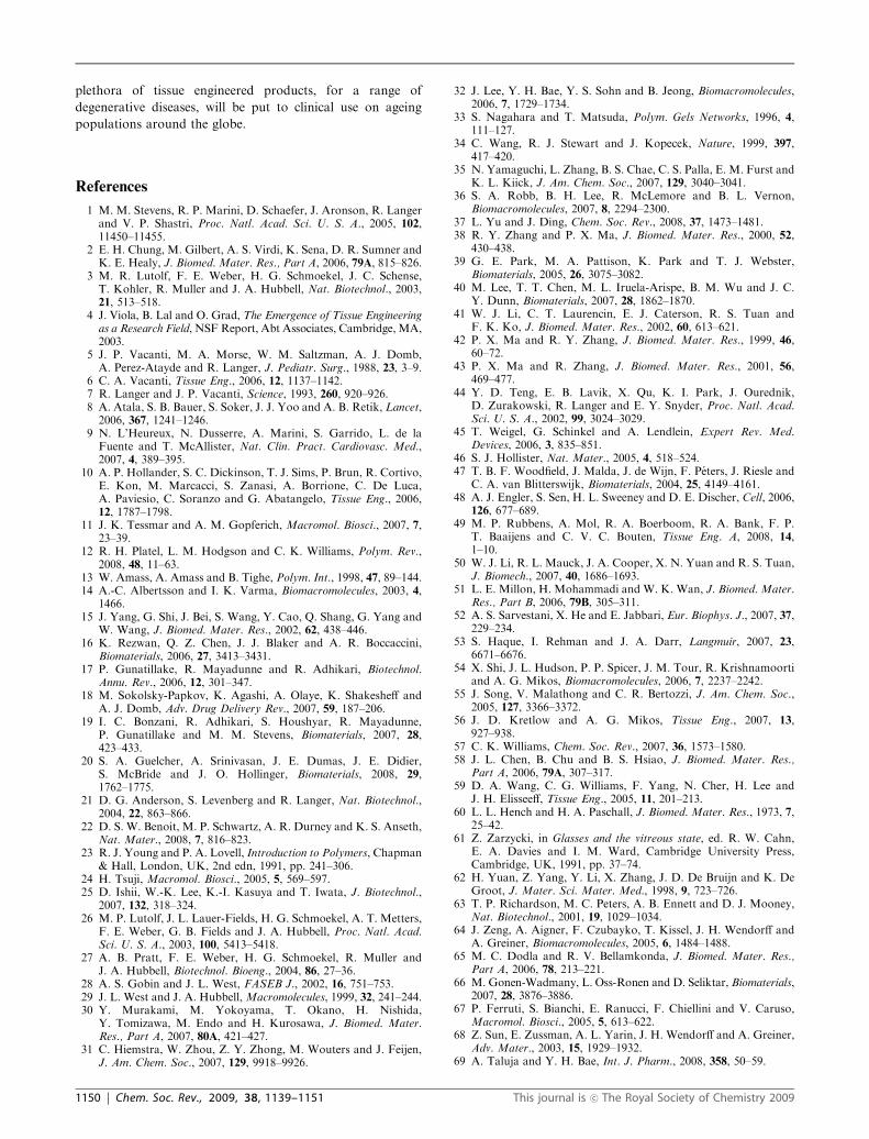
that is seen when cells are dwarfed by their substrate (Fig. 9).100
3D nanofibre scaffolds can be fabricated using electrospinning41
and thermally-induced phase separation,42 with control over
pore size and fibre dimensions. The self-assembly of block
copolymers into nanofibres has also been achieved101 although
currently is at a somewhat less advanced stage of development
than peptide self-assembly.102 Increasing the nanoscale rough-
ness of polymer surfaces also improves their resemblance to
the physical arrangement of the ECM. This can be achieved by
using nanoparticles as the reinforcing phase in composites
(including carbon nanotubes103), or by chemical etching. The
latter is simple to perform on 3D scaffolds, and the response of
a handful of cell types to treated surfaces has been analysed.
The use of different polymers or cells is sometimes seen to have
opposite effects on cellular adhesion—at least in part because
the etching process affects not only the surface roughness,
but also its chemistry. Decoupling the topographical and
chemical changes resulting from these surface treatments
remains a major challenge. Thapa et al. have used a silicone
elastomer to cast impressions of the treated surfaces, and then
used these as moulds to produce nanostructured polymers
with the same chemical properties as the bulk material. Using
this approach, an increase in bladder muscle cell numbers was
observed on both PU and PLGA.76 The differing responses of
other kinds of cells to etched and cast surfaces suggest exciting
possibilities for controlling the spatial distribution of cell
types within TE constructs.104 With each new discovery
of this nature, the potential for sophistication in scaffold
design grows.
Conclusions and future perspectives
When TE emerged as a new field in the early 1990s, there was
much excitement associated with it. This positivity led numer-
ous efforts to turn nascent concepts into reality, using techno-
logy still in its infancy, with often disappointing results. Now,
TE is entering a period of fruition, with many promising
animal and human trials published and several products
approved.105 Humans are already benefiting from lab built
organs. In constructing their tissue engineered bladders, Atala
and his team used relatively simple moulded polymers opti-
mised for mechanical compliancy.8 But as has been discussed,
the capabilities already exist to produce far more complex
scaffolds. The last decade has seen an increasing use of
biomimetics in scaffold design, aimed at producing matrices
which engage cells on a molecular level, coaxing them
into remodelling a synthetic implant into genuine tissue.
Incorporating multiple physical, chemical and biological func-
tionalities to biomaterials will yield synthetic scaffolds which
mimic the natural cell environment more closely and which
participate in a dynamic, bidirectional exchange of information
with cells.
Some of the most technologically advanced examples to
date have been hydrogels crosslinked by protease cleavable
peptides and decorated with biological functionalities includ-
ing adhesion ligands. These can be modular systems in which
any combination of bioactives can be added to a bioinert
polymer background. Notably, the synthetic process used by
the Hubbell group allows any thiolated proteins or peptides
to be included in PEG hydrogels by reaction with
bis(a,o-vinylsulfone)poly(ethylene glycol) before crosslinking.3
Elsewhere, Chung et al. have produced semi-interpenetrating
polymer networks for bone regeneration.2 They used
PNIPAAm for its thermogelling property, and grafted MMP
degradable crosslinkers and integrin-binding peptides onto
linear PAA chains to allow invasion by osteoblasts. This
polymer network supported new bone formation in vivo
following injection into a treatment site in rat femora—even
without the inclusion of cells or costly growth factors.2 If in
some cases, through the use of inductive material scaffolds,
one can circumvent the prolonged and expensive process of
expanding huge numbers of cells of host or donor origin, this
will improve the ease with which effective, sterile products for
regenerating functional tissues and organs can be produced.
These examples demonstrate that bioactivity can be con-
ferred onto previously bioinert synthetic polymers, potentially
generating materials that combine versatile material properties
and inexpensive production with control over cell behaviour.
Scaffolds based on naturally derived materials are widely used,
including in many commercial products, and will remain an
excellent choice for many applications. Other applications,
however, are likely to be better served by materials whose
mechanical properties and degradation profiles can be closely
controlled, and which may be modified in a variety of ways to
suit a particular purpose. In this way, taking our cues from
nature, we can produce synthetic scaffold materials that
actively instruct cells to regenerate tissue in damaged areas.
Already the emergence of sophisticated materials with exciting
in vivo results suggests that in the not too distant future a
Fig. 9 Cell–substrate interactions. Scaffolds having feature dimen-
sions much larger than the width of a cell effectively present a two-
dimensional surface to the cell. If the surface is endowed with adhesion
ligands the cell will flatten as it adheres and spreads. In contrast, cells
within fibrous scaffolds may be involved in matrix interactions in three
dimensions, similar to their experience within the fibrous environment
of the natural ECM. More naturalistic cell spreading, occurring in
three dimensions, is seen. Modified with permission from ref. 95,
Copyright (2005) AAS Publications.
This journal is �c The Royal Society of Chemistry 2009 Chem. Soc. Rev., 2009, 38, 1139–1151 | 1149
plethora of tissue engineered products, for a range of
degenerative diseases, will be put to clinical use on ageing
populations around the globe.
References
1 M. M. Stevens, R. P. Marini, D. Schaefer, J. Aronson, R. Langerand V. P. Shastri, Proc. Natl. Acad. Sci. U. S. A., 2005, 102,11450–11455.
2 E. H. Chung, M. Gilbert, A. S. Virdi, K. Sena, D. R. Sumner andK. E. Healy, J. Biomed. Mater. Res., Part A, 2006, 79A, 815–826.
3 M. R. Lutolf, F. E. Weber, H. G. Schmoekel, J. C. Schense,T. Kohler, R. Muller and J. A. Hubbell, Nat. Biotechnol., 2003,21, 513–518.
4 J. Viola, B. Lal and O. Grad, The Emergence of Tissue Engineeringas a Research Field, NSF Report, Abt Associates, Cambridge, MA,2003.
5 J. P. Vacanti, M. A. Morse, W. M. Saltzman, A. J. Domb,A. Perez-Atayde and R. Langer, J. Pediatr. Surg., 1988, 23, 3–9.
6 C. A. Vacanti, Tissue Eng., 2006, 12, 1137–1142.7 R. Langer and J. P. Vacanti, Science, 1993, 260, 920–926.8 A. Atala, S. B. Bauer, S. Soker, J. J. Yoo and A. B. Retik, Lancet,2006, 367, 1241–1246.
9 N. L’Heureux, N. Dusserre, A. Marini, S. Garrido, L. de laFuente and T. McAllister, Nat. Clin. Pract. Cardiovasc. Med.,2007, 4, 389–395.
10 A. P. Hollander, S. C. Dickinson, T. J. Sims, P. Brun, R. Cortivo,E. Kon, M. Marcacci, S. Zanasi, A. Borrione, C. De Luca,A. Paviesio, C. Soranzo and G. Abatangelo, Tissue Eng., 2006,12, 1787–1798.
11 J. K. Tessmar and A. M. Gopferich, Macromol. Biosci., 2007, 7,23–39.
12 R. H. Platel, L. M. Hodgson and C. K. Williams, Polym. Rev.,2008, 48, 11–63.
13 W. Amass, A. Amass and B. Tighe, Polym. Int., 1998, 47, 89–144.14 A.-C. Albertsson and I. K. Varma, Biomacromolecules, 2003, 4,
1466.15 J. Yang, G. Shi, J. Bei, S. Wang, Y. Cao, Q. Shang, G. Yang and
W. Wang, J. Biomed. Mater. Res., 2002, 62, 438–446.16 K. Rezwan, Q. Z. Chen, J. J. Blaker and A. R. Boccaccini,
Biomaterials, 2006, 27, 3413–3431.17 P. Gunatillake, R. Mayadunne and R. Adhikari, Biotechnol.
Annu. Rev., 2006, 12, 301–347.18 M. Sokolsky-Papkov, K. Agashi, A. Olaye, K. Shakesheff and
A. J. Domb, Adv. Drug Delivery Rev., 2007, 59, 187–206.19 I. C. Bonzani, R. Adhikari, S. Houshyar, R. Mayadunne,
P. Gunatillake and M. M. Stevens, Biomaterials, 2007, 28,423–433.
20 S. A. Guelcher, A. Srinivasan, J. E. Dumas, J. E. Didier,S. McBride and J. O. Hollinger, Biomaterials, 2008, 29,1762–1775.
21 D. G. Anderson, S. Levenberg and R. Langer, Nat. Biotechnol.,2004, 22, 863–866.
22 D. S. W. Benoit, M. P. Schwartz, A. R. Durney and K. S. Anseth,Nat. Mater., 2008, 7, 816–823.
23 R. J. Young and P. A. Lovell, Introduction to Polymers, Chapman& Hall, London, UK, 2nd edn, 1991, pp. 241–306.
24 H. Tsuji, Macromol. Biosci., 2005, 5, 569–597.25 D. Ishii, W.-K. Lee, K.-I. Kasuya and T. Iwata, J. Biotechnol.,
2007, 132, 318–324.26 M. P. Lutolf, J. L. Lauer-Fields, H. G. Schmoekel, A. T. Metters,
F. E. Weber, G. B. Fields and J. A. Hubbell, Proc. Natl. Acad.Sci. U. S. A., 2003, 100, 5413–5418.
27 A. B. Pratt, F. E. Weber, H. G. Schmoekel, R. Muller andJ. A. Hubbell, Biotechnol. Bioeng., 2004, 86, 27–36.
28 A. S. Gobin and J. L. West, FASEB J., 2002, 16, 751–753.29 J. L. West and J. A. Hubbell, Macromolecules, 1999, 32, 241–244.30 Y. Murakami, M. Yokoyama, T. Okano, H. Nishida,
Y. Tomizawa, M. Endo and H. Kurosawa, J. Biomed. Mater.Res., Part A, 2007, 80A, 421–427.
31 C. Hiemstra, W. Zhou, Z. Y. Zhong, M. Wouters and J. Feijen,J. Am. Chem. Soc., 2007, 129, 9918–9926.
32 J. Lee, Y. H. Bae, Y. S. Sohn and B. Jeong, Biomacromolecules,2006, 7, 1729–1734.
33 S. Nagahara and T. Matsuda, Polym. Gels Networks, 1996, 4,111–127.
34 C. Wang, R. J. Stewart and J. Kopecek, Nature, 1999, 397,417–420.
35 N. Yamaguchi, L. Zhang, B. S. Chae, C. S. Palla, E. M. Furst andK. L. Kiick, J. Am. Chem. Soc., 2007, 129, 3040–3041.
36 S. A. Robb, B. H. Lee, R. McLemore and B. L. Vernon,Biomacromolecules, 2007, 8, 2294–2300.
37 L. Yu and J. Ding, Chem. Soc. Rev., 2008, 37, 1473–1481.38 R. Y. Zhang and P. X. Ma, J. Biomed. Mater. Res., 2000, 52,
430–438.39 G. E. Park, M. A. Pattison, K. Park and T. J. Webster,
Biomaterials, 2005, 26, 3075–3082.40 M. Lee, T. T. Chen, M. L. Iruela-Arispe, B. M. Wu and J. C.
Y. Dunn, Biomaterials, 2007, 28, 1862–1870.41 W. J. Li, C. T. Laurencin, E. J. Caterson, R. S. Tuan and
F. K. Ko, J. Biomed. Mater. Res., 2002, 60, 613–621.42 P. X. Ma and R. Y. Zhang, J. Biomed. Mater. Res., 1999, 46,
60–72.43 P. X. Ma and R. Zhang, J. Biomed. Mater. Res., 2001, 56,
469–477.44 Y. D. Teng, E. B. Lavik, X. Qu, K. I. Park, J. Ourednik,
D. Zurakowski, R. Langer and E. Y. Snyder, Proc. Natl. Acad.Sci. U. S. A., 2002, 99, 3024–3029.
45 T. Weigel, G. Schinkel and A. Lendlein, Expert Rev. Med.Devices, 2006, 3, 835–851.
46 S. J. Hollister, Nat. Mater., 2005, 4, 518–524.47 T. B. F. Woodfield, J. Malda, J. de Wijn, F. Peters, J. Riesle and
C. A. van Blitterswijk, Biomaterials, 2004, 25, 4149–4161.48 A. J. Engler, S. Sen, H. L. Sweeney and D. E. Discher, Cell, 2006,
126, 677–689.49 M. P. Rubbens, A. Mol, R. A. Boerboom, R. A. Bank, F. P.
T. Baaijens and C. V. C. Bouten, Tissue Eng. A, 2008, 14,1–10.
50 W. J. Li, R. L. Mauck, J. A. Cooper, X. N. Yuan and R. S. Tuan,J. Biomech., 2007, 40, 1686–1693.
51 L. E. Millon, H. Mohammadi and W. K. Wan, J. Biomed. Mater.Res., Part B, 2006, 79B, 305–311.
52 A. S. Sarvestani, X. He and E. Jabbari, Eur. Biophys. J., 2007, 37,229–234.
53 S. Haque, I. Rehman and J. A. Darr, Langmuir, 2007, 23,6671–6676.
54 X. Shi, J. L. Hudson, P. P. Spicer, J. M. Tour, R. Krishnamoortiand A. G. Mikos, Biomacromolecules, 2006, 7, 2237–2242.
55 J. Song, V. Malathong and C. R. Bertozzi, J. Am. Chem. Soc.,2005, 127, 3366–3372.
56 J. D. Kretlow and A. G. Mikos, Tissue Eng., 2007, 13,927–938.
57 C. K. Williams, Chem. Soc. Rev., 2007, 36, 1573–1580.58 J. L. Chen, B. Chu and B. S. Hsiao, J. Biomed. Mater. Res.,
Part A, 2006, 79A, 307–317.59 D. A. Wang, C. G. Williams, F. Yang, N. Cher, H. Lee and
J. H. Elisseeff, Tissue Eng., 2005, 11, 201–213.60 L. L. Hench and H. A. Paschall, J. Biomed. Mater. Res., 1973, 7,
25–42.61 Z. Zarzycki, in Glasses and the vitreous state, ed. R. W. Cahn,
E. A. Davies and I. M. Ward, Cambridge University Press,Cambridge, UK, 1991, pp. 37–74.
62 H. Yuan, Z. Yang, Y. Li, X. Zhang, J. D. De Bruijn and K. DeGroot, J. Mater. Sci. Mater. Med., 1998, 9, 723–726.
63 T. P. Richardson, M. C. Peters, A. B. Ennett and D. J. Mooney,Nat. Biotechnol., 2001, 19, 1029–1034.
64 J. Zeng, A. Aigner, F. Czubayko, T. Kissel, J. H. Wendorff andA. Greiner, Biomacromolecules, 2005, 6, 1484–1488.
65 M. C. Dodla and R. V. Bellamkonda, J. Biomed. Mater. Res.,Part A, 2006, 78, 213–221.
66 M. Gonen-Wadmany, L. Oss-Ronen and D. Seliktar, Biomaterials,2007, 28, 3876–3886.
67 P. Ferruti, S. Bianchi, E. Ranucci, F. Chiellini and V. Caruso,Macromol. Biosci., 2005, 5, 613–622.
68 Z. Sun, E. Zussman, A. L. Yarin, J. H. Wendorff and A. Greiner,Adv. Mater., 2003, 15, 1929–1932.
69 A. Taluja and Y. H. Bae, Int. J. Pharm., 2008, 358, 50–59.
1150 | Chem. Soc. Rev., 2009, 38, 1139–1151 This journal is �c The Royal Society of Chemistry 2009
70 A. H. Zisch, M. P. Lutolf, M. Ehrbar, G. P. Raeber, S. C. Rizzi,N. Davies, H. Schmokel, D. Bezuidenhout, V. Djonov, P. Zillaand J. A. Hubbell, FASEB J., 2003, 17, 2260–2262.
71 M. Ehrbar, S. M. Zeisberger, G. P. Raeber, J. A. Hubbell,C. Schnell and A. H. Zisch, Biomaterials, 2008, 29, 1720–1729.
72 Z. Ma, Z. Mao and C. Gao, Colloids Surf., B, 2007, 60, 137–157.73 A. Kikuchi and T. Okano, J. Controlled Release, 2005, 101,
69–84.74 H. R. Allcock, L. B. Steely, S. H. Kim, J. H. Kim and B. K. Kang,
Langmuir, 2007, 23, 8103–8107.75 Z. W. Ma, W. He, T. Yong and S. Ramakrishna, Tissue Eng.,
2005, 11, 1149–1158.76 A. Thapa, D. C. Miller, T. J. Webster and K. M. Haberstroh,
Biomaterials, 2003, 24, 2915–2926.77 Y. B. Zhu, M. F. Leong, W. F. Ong, M. B. Chan-Park and
K. S. Chian, Biomaterials, 2007, 28, 861–868.78 H. S. Choi, H. Suh, J. H. Lee, S. N. Park, S. H. Shin, Y. H. Kim,
S. M. Chung, H. K. Kim, J. Y. Lim and H. S. Kim, Eur. Arch.Otorhinolaryngol., 2008, 265, 809–816.
79 U. Edlund, M. Kallrot and A. C. Albertsson, J. Am. Chem. Soc.,2005, 127, 8865–8871.
80 R. A. Quirk, M. C. Davies, S. J. B. Tendler and K. M. Shakesheff,Macromolecules, 2000, 33, 258–260.
81 A. Lucke, J. Tessmar, E. Schnell, G. Schmeer and A. Gopferich,Biomaterials, 2000, 21, 2361–2370.
82 Y. Zhu, C. Gao, T. He, X. Liu and J. Shen, Biomacromolecules,2003, 4, 446–452.
83 H. F. Jia, G. Y. Zhu, B. Vugrinovich, W. Kataphinan,D. H. Reneker and P. Wang, Biotechnol. Prog., 2002, 18,1027–1032.
84 B. K. Brandley and R. L. Schnaar, Anal. Biochem., 1988, 172,270–278.
85 R. Haubner, R. Gratias, B. Diefenbach, S. L. Goodman,A. Jonczyk and H. Kessler, J. Am. Chem. Soc., 1996, 118,7461–7472.
86 D. L. Hern and J. A. Hubbell, J. Biomed. Mater. Res., 1998, 39,266–276.
87 S. P. Massia and J. A. Hubbell, J. Cell Biol., 1991, 114,1089–1100.
88 J. Salber, S. Grater, M. Harwardt, M. Hofmann, D. Klee,J. Dujic, J. H. Huang, J. D. Ding, S. Kippenberger, A.Bernd, J. Groll, J. P. Spatz and M. Moller, Small, 2007, 3,1023–1031.
89 L. M. Weber, K. N. Hayda, K. Haskins and K. S. Anseth,Biomaterials, 2007, 28, 3004–3011.
90 M. Heyde, M. Moens, L. Van Vaeck, K. M. Shakesheff,M. C. Davies and E. H. Schacht, Biomacromolecules, 2007, 8,1436–1445.
91 D. S. W. Benoit and K. S. Anseth, Biomaterials, 2005, 26,5209–5220.
92 D. R. Schmidt and W. J. Kao, J. Biomed. Mater. Res., Part A,2007, 83, 617–625.
93 A. I. Teixeira, P. F. Nealey and C. J. Murphy, J. Biomed. Mater.Res., Part A, 2004, 71, 369–376.
94 E. K. Yim, R. M. Reano, S. W. Pang, A. F. Yee, C. S. Chen andK. W. Leong, Biomaterials, 2005, 26, 5405–5413.
95 M. M. Stevens and J. H. George, Science, 2005, 310,1135–1138.
96 G. Maheshwari, G. Brown, D. A. Lauffenburger, A. Wells andL. G. Griffith, J. Cell Sci., 2000, 113, 1677–1686.
97 W. A. Comisar, N. H. Kazmers, D. J. Mooney andJ. J. Linderman, Biomaterials, 2007, 28, 4409–4417.
98 D. J. Irvine, A. M. Mayes and L. G. Griffith, Biomacromolecules,2001, 2, 85–94.
99 D. J. Irvine, A. V. Ruzette, A. M. Mayes and L. G. Griffith,Biomacromolecules, 2001, 2, 545–556.
100 E. Cukierman, R. Pankov, D. R. Stevens and K. M. Yamada,Science, 2001, 294, 1708–1712.
101 G. Liu, L. Qiao and A. Guo, Macromolecules, 1996, 29,5508–5510.
102 R. J. Mart, R. D. Osborne, M. M. Stevens and R. V. Ulijn, SoftMatter, 2006, 2, 822–835.
103 G. Jell, R. Verdejo, L. Safinia, M. Shaffer, M. Stevens andA. Bismarck, J. Mater. Chem., 2008, 18, 1865–1872.
104 D. C. Miller, A. Thapa, K. M. Haberstroh and T. J. Webster,Biomaterials, 2004, 25, 53–61.
105 M. J. Lysaght, A. Jaklenec and E. Deweerd, Tissue Eng. A, 2008,14, 305–315.
This journal is �c The Royal Society of Chemistry 2009 Chem. Soc. Rev., 2009, 38, 1139–1151 | 1151
Top Related