


![Micromechanics of ferroelectric polymer-based electrostrictive …depts.washington.edu/mfml/Contents/Paper_Li/Li_JMPS_PVDF.pdf · 2009-02-17 · [P(VDF-TrFE)] polymer-based composite,](https://static.fdocuments.us/doc/165x107/5f437db5de860906673fc501/micromechanics-of-ferroelectric-polymer-based-electrostrictive-depts-2009-02-17.jpg)


Languages
Pages
Legal


1
SYNTHESIS AND CHARACTERIZATION OF POLYMER-
FERROELECTRIC COMPOSITE MATERIAL
A THESIS SUBMITTED IN PARTIAL FULFILLMENT OF THE REQUIREMENTS FOR THE DEGREE OF
Master of Science in Physics
By
Subhasmita Swain
DEPARTMENT OF PHYSICS NATIONAL INSTITUTE OF TECHNOLOGY
ROURKELA – 769008

2
SYNTHESIS AND CHARACTERIZATION OF POLYMER-
FERROELECTRIC COMPOSITE MATERIAL
A THESIS SUBMITTED IN PARTIAL FULFILLMENT OF THE REQUIREMENTS FOR THE DEGREE OF
Master of Science in Physics
By
Subhasmita Swain
Under the guidance of
Prof. S.Panigrahi
DEPARTMENT OF PHYSICS NATIONAL INSTITUTE OF TECHNOLOGY
ROURKELA – 769008

3
Department of Physics National Institute of Technology
Rourkela – 769008 (Orissa)
CERTIFICATE This is to certify that this Thesis entitled “Synthesis and characterization
of Polymer ferroelectric composite material” submitted by Subhasmita
Swain in partial fulfilments for the requirements for the award of degree of
Master of Science in Physics at National Institute of Technology, Rourkela is
an authentic work carried out by her under my supervision and guidance.
To the best of my knowledge, the matter embodied in the project has not
been submitted to any other University/ Institute for the award of any Degree or
Diploma.
Rourkela Prof. S. Panigrahi
Date: 13.05.2011 Department Of physics
National Institute Of Technology
Rourkela-769008

4
ACKNOWLEDGEMENT Before presenting the thesis work, I would like to mention a few words for the people who
gave their complete support for my thesis work.
My first thanks are to the Almighty God, without whose blessings I wouldn't have been
writing this “acknowledgments”.
Then I take this opportunity to express my deep regards and sincere gratitude for this
valuable, expert guidance rendered to me by guide Prof. S. Panigrahi, Department of Physics,
National Institute of Technology Rourkela. I consider me fortunate to have had opportunity to
work under his guidance and enrich myself from his vast knowledge and analysis power.
My sincere thanks to Dr. Siddhartha Jena, Professor and Head of Physics Department for his
talented advice and providing necessary facility for my work.
I am especially indebted to Dr.Tanmaya Badapanda for teaching me both research and
writing skills, which have been proven beneficial for my current research and future career.
Without his endless efforts, knowledge, patience, and answers to my numerous questions, this
research would have never been possible.
My deep sense of gratitude to PhD Scholar, Mr. Senthil.V, department of Physics, for his
valuable suggestions and constant help for this work. He has been very kind and patient while
suggesting me the outlines of this project and has clarified all my doubts whenever I
approached him.
I record my sincere thanks to Department of Ceramic Engineering, for the help in taking
XRD, Department of Metallurgical and Material Science for extending all facilities to carry
out the SEM.
I am greatly thankful to all the research scholars of the department and my class mates for
their inspiration and help.
Last but not the least; I would like to express my gratefulness to my parents for their endless
support, without which I could not complete my project work.
Date :13.05.2011
Subhasmita swain

5
Dedicated
To my family and my friends

6
ABSTRACT
Among all the research fields in material science Polymer Composites are the most
rapidly growing one .Polymer Composite materials are adding a great deal of material that is
more durable and useful as compared to the conventional material. Ferroelectric ceramics
possess high dielectric permittivity but with poor mechanical properties and lower
dielectric breakdown strength. By integrating high dielectric permittivity ceramic
powder with superior dielectric strength of the polymer, one can develop a composite
with high dielectric permittivity and high breakdown strength. This type of composites
has high capability of energy storage and can be used in capacitors and energy storage
device.
[Ba1-xY2x/3](Zr0.1Ti0.9)O3 powders with different yttrium concentrations (x=0,
0.01, 0.02, 0.03) were Prepared by solid state reaction. These powders were analyzed by X-
ray diffraction (XRD). The polymer ceramic composites were prepared using polyvinyl
alcohol (PVA) as polymer matrix and Ba1-xY2x/3Zr0.1Ti0.9O3 (BYZT) as ceramics
powder by hot pressing technique. The microstructure/surface morphology of the
composite was analyzed by scanning electron microscope. Also we have conducted an
analysis of the XRD study of Polymer Composites of Poly (vinyl alcohol) with barium
titanate. Hot pressed samples are studied the dielectric and impedance spectroscopy.

7
CONTENTS
Page no.
Chapter 1 Introduction 8
1.1 Ferro electricity 8
1.2 Piezoelectricity 9
1.3 Pyroelectricity 10
1.4 Pervoskite crystal structure 11
1.5 Barium Titanate 11
1.6 Polymer Composite 12
Chapter 2 2.1 Motivation 14
2.2 Thesis Objective 14
Chapter 3 Experimental techniques 15
3.1 X-ray Diffraction study 15
3.2 Scanning electron microscope 15
3.3 Dielectric study 16
3.4 Impedance study 16
3.5 Preparation of ceramic powder 17
3.6 Preparations of Polymer Composite 17
Chapter 4 4.1 Introduction on BZT 19
4.2 Result and discussion 20
4.2.1 XRD of BYZT 20
Chapter 5 5.1 Polymer Composite 21
5.2 Result and Discussion 22
5.2.1 XRD of Polymer Composite 22
5.2.2 SEM of Polymer Composite 23
5.2.3 Dielectric Study of Polymer Composite 24
5.2.3.1 Temperature dependence of dielectric constant 24
5.2.3.2 Frequency dependence of dielectric constant 25
5.2.3.3 Frequency dependence of dielectric loss 26
5.2.3.4 Complex Impedance spectroscopy 27
Chapter -6 Conclusion 29
References

8
CHAPTER-1
1. Introduction:
In the recent years Polymer composite materials have been widely used because of their
significant importance. Now the research is rapidly going on ferroelectric composite
materials because of their various applications due to their excellent properties. Ferroelectric
materials have been of great technological interest due to their excellent properties in various
applications. Ferro electricity was first discovered by J.Valasek in 1920.
1.1 Ferro electricity:
When the polarization of the dielectric can be altered by an electric field, it is called
ferroelectric. Ferroelectric materials are generally single crystal or polycrystalline ceramic
oxides. Ferroelectric materials belong to pyroelectric family. Ceramics are the single crystals
because they are easy to synthesize. The first known ferroelectric material found was
Rochelle salt in 1921. Then Barium Titan ate (BaTiO3) was discovered to ferroelectric
material. In this material the centre of the positive and negative charges does not coincide
even without the application of external electric field. It has some properties i.e. they have
spontaneous polarization and they exhibit Hysteresis loop. All ferroelectric materials are
piezoelectric and pyroelectric but reverse is not possible. The use of ferroelectric materials is
RAM for computers, also used in medical ultrasound machine. The ferroelectric materials
having domains i.e. the region in which all electric dipoles are aligned in same direction. The
variation of polarization with electric field is not linear.
Fig. 1.1: A Polarization vs. Electric Field (P-E) hysteresis loop for a typical ferroelectric
crystal.

9
Here is the P-E loop. We are getting that if we are increasing the field strength the domains
start to align in the positive direction which gives rise the increase in polarization. After a
certain field the polarization reaches a saturation value. Then if the external field is removed
the polarisation does not fall to zero, some polarization is there and this is called remanant
polarization. The crystal cannot be completely depolarised until a field of magnitude (OF) is
applied and this field is called coercive field (Ec).If the field is increased to more negative
value direction of polarisation flips and hence a hysteresis loop is obtained.
1.2 Piezoelectricity:
All ferroelectric materials are piezoelectric. Piezoelectric materials show direct piezoelectric
effect and converse effect. i.e these materials having an ability to develop an electrical charge
proportional to mechanical stress and a geometrical strain is produced on the application of
voltage respectively. It is the interaction between mechanical and electrical state.
D = ƐE (direct effect)
Where D= electric charge displacement vector
E =electric field strength
Ɛ = permittivity
S = sT (converse effect)
Where S=stress
s=compliance
T=strain
Piezoelectric properties are dependent on orientation direction, so they must be described in
terms of tensors. i.e.
Pi = dijαjk (Direct Piezoelectric Effect)
βij = dijEk(Converse Piezoelectric Effect)

10
Piezoelectric materials having so many applications i.e. they can be used as transducer,
actuator and sensor.
1.3 Pyroelectricity:
The spontaneous polarization which depends upon temperature is called pyroelectric effect.
We know that out of 32 crystal classes 11 are centrosymmetry and 21 are non-
centrosymmetry and 10 out of 21 are pyroelectric.
∆Ps = ∏∆T
Here ∆Ps = spontaneous polarization
∏ = Pyroelectric co-efficient
∆T = change in temperature
That means spontaneous polarization depends upon temperature.An increase in temperature
gives decrease in spontaneous polarisation. Polarisation suddenly falls to zero on heating
above a particular temperature.
Fig. 1.2: The temperature dependence of spontaneous polarization Ps for BaTiO3 ferroelectric
crystal.
11
1.4 Pervoskite crystal structure:
Ferroelectric structure is of 4-types. i.e.
1. Pervoskite structure
2. Bismuth layer structure
3. Tungsten-Bronze structure
4. Pyrochlore structure
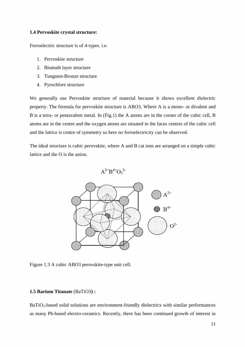
We generally use Pervoskite structure of material because it shows excellent dielectric
property. The formula for pervoskite structure is ABO3. Where A is a mono- or divalent and
B is a tetra- or pentavalent metal. In (Fig.1) the A atoms are in the corner of the cubic cell, B
atoms are in the centre and the oxygen atoms are situated in the faces centres of the cubic cell
and the lattice is centre of symmetry so here no ferroelectricity can be observed.
The ideal structure is cubic perovskite, where A and B cat ions are arranged on a simple cubic
lattice and the O is the anion.
Figure 1.3 A cubic ABO3 perovskite-type unit cell.
1.5 Barium Titanate (BaTiO3) :
BaTiO3-based solid solutions are environment-friendly dielectrics with similar performances
as many Pb-based electro-ceramics. Recently, there has been continued growth of interest in
12
the use of BaTiO3-based ceramics, because they are promising materials for tunable
microwave device application such as electronically tunable mixers, delay lines, filters,
capacitors, resonators and phase shifters. They possess the following properties which is
required for device application
High dielectric constant
Large tunability;
Low loss tangent
And good thermal stability
Barium titanate (BT) is can be used in various forms, e.g. bulk, thin and thick films, powder,
in a number of applications).it has a paraelectric cubic phase transition above its Curie point
of about 130° C. Barium titanate is a ferroelectric ceramic material, with a photorefractive
effect and piezoelectric properties. It has five phases as a solid, listing from high temperature
to low temperature: hexagonal, cubic, tetragonal, orthorhombic, and rhombohedral crystal
structure. All of the structures exhibit the ferroelectric effect except cubic.
1.6 Polymer composite
Polymer composite is composites made from polymers or from polymers along with
other kinds of materials.
Polymer + Ceramic = polymer composite
Combination of both can overcome the drawbacks of each individual.
The composite materials are heterogeneous in nature. There has been a rapidly increasing
search for the materials which can replace conventional material. Those ideal structural
materials should have low densities, high tensile strength, and high stiffness. Polymer
composite material is up to greater extend fulfilling the demand for such material. As the
Fabrication of composite materials is nothing but the combination of two or more different
materials having different properties to obtain the desirable material properties that often
cannot be obtained in single-phase materials. Polymer has some merits and also some
demerits. It has good mechanical property, easy to synthesis, low acoustic impedance, and
high dielectric break down strength and the demerit is low dielectric constant. Like that
ceramics have some merits and demerits. It has poor mechanical properties, high acoustic

13
impedance, and high dielectric constant and lower dielectric breakdown strength. When we
add polymer with ceramic they we can overcome these problems. That means polymer
composites have good mechanical properties, low acoustic impedance, intermediate dielectric
constant and high breakdown strength. Polymer composites are in demand due to their
potential application in batteries, electrochemical sensor, capacitor and transducer.
As we know in technical application the role of energy storage device have tremendous role
like computers, communication devices, industrial controls, electric vehicles, space ships etc.
Because of excellent mechanical, thermal stability and high ionic conductivity of polymer
composite it is used for the said application.

14
CHAPTER -2
2.1 Motivation
Recent years have witnessed constant search for high permittivity materials that have wide
range of technologically important applications such as microelectronic, embedded passive,
and electrostrictive devices [1,2]. Majority of the electronic component in microelectronic
circuits are passive and occupy more than 80% of the printed wired surface area. Integration
of embedded passive components into printed circuit board offers a significant reduction in
size, better electrical performance, reliability, lower cost and improved design options.
Among embedded passive components, the embedded capacitor is particularly favorable
because they are used in large number of various functions such as decoupling, bypassing,
energy storage and filtering capacitors. One major challenge for implementing the embedded
capacitor technology is the development of new dielectric material that possesses good
dielectric and mechanical properties and process abilities.
2.2 Thesis objective:
The objective of my thesis is
Preparation of Yttrium doped BaZr0.1Ti0.9O3 (BZT) ceramic with general formula
Ba1-xY2x/3Zr0.1Ti0.9O3 (BYZT) by solid state method.
Structural study of by XRD.
Fabrication of polymer composite.
Structural and Micro structural study of Polymer composite by XRD and SEM.
Study of Electrical behavior of polymer composite by dielectric and impedance
spectroscopy.
Polyvinyl alcohol (PVA) used as polymer due to some excellent properties of
polymers like it is a water soluble polymer, and it has excellent adhesive property.
Also it has high tensile strength and flexibility.

15
CHAPTER-3
3. Experimental Techniques
Our aim is to prepare polymer ferroelectric composite. First ceramic powders are prepared
and then by mixing these ceramics with polymer polymer composite are prepared. The
general formula of the ceramic material is Ba1-x Y2x-3 Zr0.1 Ti0.9 O3 (BYZT). A site modified
Ba1-x Y2x-3 Zr0.1 Ti0.9 O3 ceramics has synthesised with the dopant Yttrium (x=0, 0.01, 0.02,
0.03) by conventional solid state reaction method.
To understand the structural, electrical properties of a material used different characterization
methods.
3.1 X-ray Diffraction Study:
As we know the physical properties of solid i.e. optical, electrical, magnetic, ferroelectric
etc depends on atomic arrangements of materials so X-Ray Diffraction pattern (XRD) is a
very important tool for material characterization. So for the determination of a structure of
material and the fingerprint characterization of a material we are using XRD. When the
highly energetic X-Ray beams strikes the atom of the crystal surface they scatter in different
direction. In few directions these waves obey Bragg’s condition.
i.e 2d sinθ = nλ
By XRD study we can know how the atoms are pack in the crystal, interatomic distance,
angle, phase composition.
3.2 Scanning electron microscope:
SEM is used for the study of topographies, morphology and the composition of the
material at high magnification. The principle of SEM is a highly energetic electron beam
emitted from an electron gun fitted with a Tungsten filament cathode strikes the sample as a
result the secondary electrons-Rays and back scattered electrons are ejected from the sample.
These electrons convert into the signal and that displays on the screen. In SEM depth of field
is so a large amount of the sample can be focus at one time. The image produce in SEM have
very high resolution that means closely packed features can be examined at a high
magnification.

16
3.3 Dielectric study:
To measure the capacitance, dissipation factor, and dielectric constant we need dielectric
measurement. Dielectrics are such materials which are ideal insulators which would have no
free electrons. A dielectric material has the interesting properties that of the ability of an
electric field to polarize the material to create electric dipoles. The dielectric study is
concerned with the storage and dissipation of electric and magnetic energy in material.
3.4 Impedance study:
The impedance |Z| and the phase difference (θ) between the voltage and current are measured
as a function of frequency for the given sample and the technique is called impedance
spectroscopy. To study the electrical properties of the complex pervoskite material we
generally use impedance spectroscopy. This involves very simple electrical measurements
and the results we get can be correlated with the properties i.e. microstructure, defects,
dielectric properties, chemical reaction etc .In this technique we can separate the grains and
grain boundaries. Impedance plot takes place between the imaginary part of the impedance
Z”=|Z|cosθ against the real part Z’=|Z|sinθ on a complex plane. The impedance can be
expressed by the following relation Z* = Z’ - jZ” = R / 1+jω RC
3.5 Preparation of ceramic powder:
For synthesis of Ba1-x Y2x-3 Zr0.1 Ti0.9 O3 (BYZT) the precursors are used Barium carbonate
(BaCO3), titanium oxide (TiO2), Zirconium Oxide (ZrO2) and Yttrium Oxide (Y2O3). All the
precursors are having 99% purity. For the preparation of 20gms, the precursors are calculated
in a stoichiometric ratio.
The precursors are mixed thoroughly in dry condition in an agate motor for 2hrs. For getting
the homogeneous mixture used ball milling technique which is a grinding process. The
process continued for 12 hrs in the liquid medium using isopropyl alcohol. Then the mixture
is dried under IR lamp and again the powders were grinded in an agate motor for 15mins. The
dried powders are kept in an alumina crucible for calcinations which is a process the material
is heated to a temperature below its melting point to get the single phase and removal of
volatile fraction. The calcination is carried out at 13500c for 4hrs and then cooled in the
furnace. Again the calcined powders are grinded in an agate motor to get the fine powder and

17
those powders used phase formation study by XRD. Preparation of the ceramic is shown
below in the flow chart.
Fig. 3.1 Flow chart for the preparation of ceramics by solid-state route
3.6 Preparation of polymer composite:
To prepare the polymer ceramic composite, polyvinyl alcohol is used as polymer. The
composition of polymer and ceramics were taken in the volume percentage ratio 100:0%,
75:25% and 50:50%.
For 100% composition
Polymer required = 1.28gm
Ceramic required = 0gm
18
For 75%+25% composition
Polymer required =0.96gm
Ceramic required = 1.505gm
For 50%+50% composition
Polymer required = 0.64gm
Ceramic required = 3.01gm
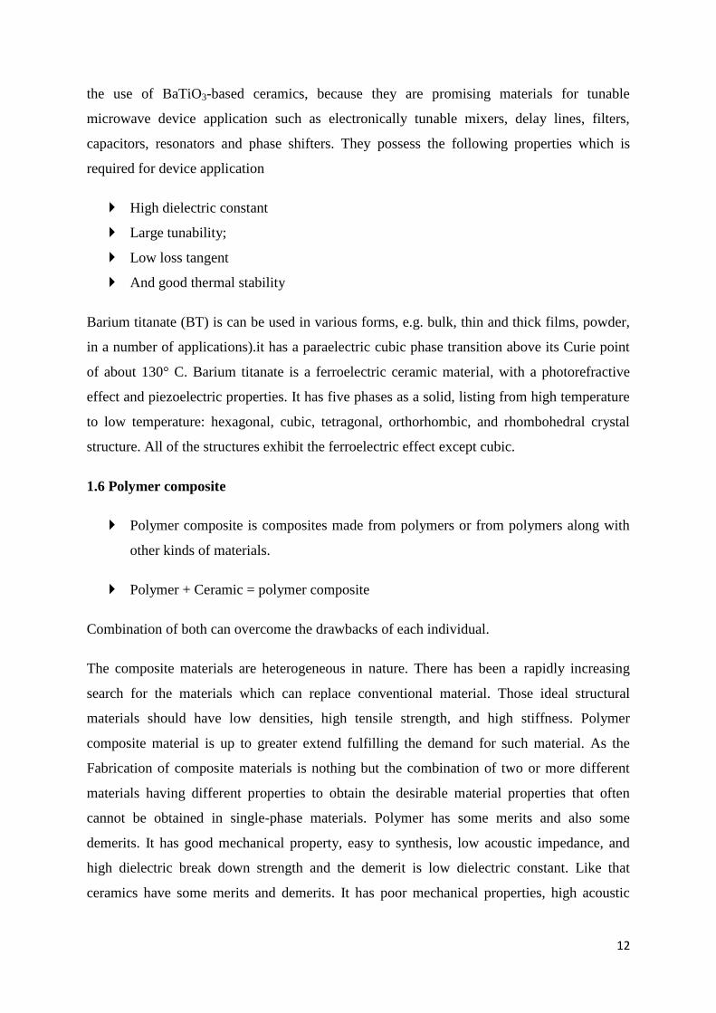
PVA dissolved in 20ml of distilled water in the hot condition. The solution is stirrered
continuously at the temperature 80oC for 2hrs to get the gel condition. After the gel
formation the ceramic mixed in volume percent ratio in the agate mortar under IR lamp for 15
mins. The mixed polymer and ceramic gel dried and become rubber like condition. Then that
composition is dried in IR lamp and its subjected to hot press to make the thick film. The
composite has hot pressed at 100oC for 2 mins using the pressure 5 tonns. Then to know the
structural, micro structural, electrical behaviour of the composite the XRD, SEM and
Dielectric and impedance studies has carried out.
Fig 3.2: flow chart for the preparation of polymer composite

19
CHAPTER -4
4.1 INTRODUCTION ON BZT:
The lead-free ceramic oxides have been widely used due to their dielectric,
ferroelectric, electromechanical and piezoelectric properties [3-8]. These materials do not
present detrimental effects to human health and environment [9-11] besides the high thermal
stability. Barium strontium titanate (Ba,Sr)TiO3 (BST) has been considered a promising
material for the development of tunable microwave devices because it has strong electric
field dependence of dielectric constant. But it has the drawback is dielectric loss at high
frequencies [12-15]. The barium zirconate titanate Ba(ZrxTi1-x)O3 (BZT) has received more
attention in the field of materials science by reason of its structural and physical properties
exhibit a significant dependency with the titanium (Ti) and zirconium (Zr) contents into the
matrix [16,17]. The dielectric properties as well as the phase transition from ferroelectric to
relaxor focused with the perovskite structure [18-20]. In order to improve the electrical
properties the BZT ceramics have been doped with different doping elements like
lanthanides, semi-metal and alkaline-earth metals such as: niobium, boron, lithium, yttrium,
copper, vanadium, manganese, tungsten, nickel, aluminium, lanthanum, bismuth and
ytterbium. However, there are few studies reported in the literature on the optical properties
of this compound. For example, Liu et al. [21] analyzed the infrared optical properties of
BZT thin films prepared by the sol gel method, using only two Zr concentrations(x = 0.20
and 0.30) into the lattice. They observed that the refractive indexes (n) of these thin films are
lower when compared with those of BaTiO3 single crystals in the wavelength range from
2500 to 12000 nm. In terms of photoluminescence (PL) measurements at room temperature,
the BZT (thin films or powders) has shown typical blue and orange emissions. In general,
phase the origin of the PL phenomenon has-been attributed to the degree of structural order
disorder into the lattice, as a consequence of the symmetry break between the O-Zr-O and O-
Ti-O bonds [22-25].Therefore, in this work, we report on the structure and optical properties
of[Ba1-xY2x/3](Zr0.1Ti0.9)O3 powders synthesized with different yttrium
(Y)concentrations(x=0.0.01,0.02and 0.03) by the solid state reaction method.

20
4.2 Result and discussion:
4.2.1 XRD of BYZT:
Fig 4.1 XRD pattern for BYZT ceramic
The above XRD patterns indicated that all powders are in a perovskite type cubic structure
with space group Pm3m, in agreement with the respective Joint Committee on Powder
Diffraction Standards (JCPDS) card No. 36-0019. Diffraction peaks related to the Y2O3
(secondary phase) were not detected in the composition upto x = 0.02, suggesting that the Y
atoms were incorporated into the [Ba1-xY2x/3] (Zr0.1Ti0.9) O3 structure. But in the x = 0.03
composition shows the some impurities (secondary phase) in the XRD pattern. The
substitution of Y in Ba sites leads to the distortions into the BZT structure because of the
different atomic radii. The literature reports that the ionic radius of Ba2+ ions is
approximately 0.161 nm, while those of Y3+ are 0.086 nm. Based on these hypotheses, we
suppose that the substitution of Ba sites commonly occupied by Y atoms causes an electronic
compensation through the formation of barium vacancies (VBax, VBa’ or VBa”). In this case,
it is very probable that the Y atoms are coordinated to six oxygen (O) atoms (distorted [YO6]
clusters), while the Ba atoms are bonded to twelve oxygen atoms ([BaO12] clusters). Hence,
the substitution processes of [BaO12] by distorted [YO6] clusters
20 30 40 50 60
(11
2)
(10
2)
(00
2)
(11
1)
(10
1)
(00
1)
(Inte
nsity)
(2
x=0.03
x=0.02
x=0.01
x=0.0
X = 0.03
X = 0.02
X = 0.01
X = 0.0

21
CHAPTER-5
5.1 Polymer composite:
Electronic systems in general consist of both the active and passive components. The
technologies concerning the development of the passive components such as resistors,
inductors, and capacitors are steadily growing in the electronic industries. Among these
passive components, the capacitor is the one which attracts special attention due to its variety
of functions that include decoupling, by-passing, filtering and timing capacitors. In recent
years much work has been done on polymer–ceramic composites. Owing to the continuous
development towards the miniaturization of electronics, high dielectric constant polymer–
ceramic composites have become promising materials for embedded capacitor applications.
Ferroelectric ceramics possessing very high dielectric constants are brittle and suffer from
poor mechanical strength.
On the other hand, polymers having low dielectric constants are flexible, easy to process and
possess high dielectric strength. New composites associated with high dielectric constant, and
high dielectric breakdown strength to achieve high volume efficiency and energy storage
density for applications of capacitors and electric energy storage devices could be fabricated
by combining the merits of polymers and ceramics.
Polyvinyl alcohol (PVA) is a good insulating material with low conductivity and hence is of
importance to microelectronic industry. It electrical conductivity depends on the thermally
generated carriers and also on the addition of suitable dopants [26,27]. Although charge
transport in polymers is a problem with great technological implication, the current
understanding of the elemental processes involved is still unsatisfactory [28]. In the present
work an attempt has been made to study the electrical transport properties of pure PVA films
and doped films of PVA with carbon black using aluminium and gold as ohmic and blocking
electrodes respectively.
Polymer–ceramic composites combine superior properties of both polymer and ceramics
which results in far better performance than those of the constituent materials. Polymers are
flexible, easy to fabricate and superior in dielectric break down strength. On the other hand,
ferroelectric ceramics possess high dielectric permittivity but with poor mechanical properties
and lower dielectric breakdown strength [29]. By integrating high dielectric permittivity
ceramic powder with superior dielectric strength of the polymer, one can develop a composite

22
with high dielectric permittivity and high breakdown strength. This type of composites has
high capability of energy storage and can be used in capacitors and energy storage devices.
The easiness of composite fabrication allows producing thin film capacitors which is difficult
to achieve in ceramics due to complicated fabrication routes.
5.2 Result and Discussion
5.2.1 XRD of polymer composite
10 20 30 40 50 60
0
100
200
300
400
inte
nsity(a
.u)
( 2)
PVA 100%
20 30 40 50 60
inte
nsity(a
.u)
(2)
x=0.0
x=0.01
Fig 5.1: XRD of polymer composite (a) PVA-BYZT100:0% and (b) PVA-BYZT75:25%
To investigate the influence of ferroelectric on polymer structure, X-ray diffraction studies
were performed for pure PVA and BZT based ferroelectric ceramic (Fig. 5.1). A broad peak
at 21° was observed in pure PVA films, and this can be attributed to the semi crystalline
behaviour of the polymer corresponding to the orthorhombic lattice structure. It is evident
from the figure that there is a relative decrease in the intensity of this peak with the increase
of dopant concentration. This may be due to the increase of amorphous nature of PVA with
the addition of ferroelectric ceramic.

23
5.2.2 SEM of Polymer Composite:
Fig 5.2 SEM images of the polymer composite thick films
Scanning electron microscopy (SEM) is often used to study the compatibility between
various components of the polymer electrolytes through the detection of phase separations
and interfaces. The compatibility between the polymer matrix and the inorganic dopants has
great influence on the properties (mechanical, thermal, ionic conductivity) of the polymer
electrolytes. The morphology of the pure PVA and PVA/BSZT 100:0% and 75:25% polymer
electrolytes, studied by SEM technique, is a uniform type but with different degrees of
roughness (Fig. 5.2). However in case of the composite the ferroelectric ceramic oxides are
distributed homogenously on the polymer matrix. In SEM micrographs of the composites, the
bright area corresponds to the ferroelectric ceramics and the dark region corresponds to the
polymer matrix.
X=0.02 X=0.03
100% PVA X=0.01

24
5.2.3 Dielectric study
5.2.3.1 Temperature dependence of dielectric constant
40 60 80 100 120
0
200
400
600
800
1000
1200
1MHz
100kHz
10kHz
1kHz
die
lectr
ic c
on
sta
nt
Temperature oC
x = 0
40 60 80 100 120
100
200
300
400
500
600
die
lectr
ic c
on
sta
nt
Temperature oC
1MHz
100kHz
10kHz
1kHz
x = 0.01
20 40 60 80 100 120
60
80
100
120
140
160
180
200
220
240
1MHz
100kHz
10kHz
1kHz
Die
lectr
ic c
on
sta
nt
Temperature oC
x = 0.02
Fig 5.3. Temperature dependence of Dielectric constant of the polymer composite for different
frequencies
The temperature dependences of the dielectric properties of PVA-BYZT (75:25%) at
different frequency fields are illustrated in Fig. 6. As shown in Fig. 6, the dielectric constant
gradually increased with increasing temperature. This observation is in other
polymer/BaTiO3 composites, where the ε’ increased with temperature [29,30]. Generally, the
change of dielectric property in the composites includes three competitive mechanisms: (a)
the segmental mobility of polymer would improve with increasing temperature, which should
facilitate the polarization of polar components and increase the dielectric constant
consequently, (b) the thermal expansion of polymer could disrupt the chains of contact
BaTiO3 particles, which should reduce the dielectric constant and (c) the structure of BaTiO3
particles could be changed with an increase in temperature (before Curie temperature), which

25
could generate a modification on the dielectric response of the ceramic [31]. According to the
above literature, the dielectric constant is increased in the polymer composite of PVA-BYZT.
Due to the dopant increment, the frequency dispersion is observed more compared to the
undoped BZT sample. And also, as the earlier report [32], dielectric constant is decreased
with increasing Y concentration. This is may be the effect of oxygen vacancies as explained
in the XRD report.
5.2.3.2 Frequency dependence of dielectric constant
100 1000 10000 100000 1000000
100
1000
30oC 40
oC
50oC 60
oC
70oC 80
oC
90oC 100
oC
110oC 120
oC
Die
lectr
ic c
on
sta
nt '
log frequency
x = 0
100 1000 10000 100000 1000000
100
1000
Die
lectr
ic c
on
sta
nt
'
log frequency
30oC 40
oC
50oC 60
oC
70oC 80
oC
90oC 100
oC
110oC 120
oC
x = 0.01
100 1000 10000 100000 1000000
100
1000
30oC 40
oC
50oC 60
oC
70oC 80
oC
90oC 100
oC
110oC 120
oC
Die
lectr
ic c
on
sta
nt
'
log frequency
x = 0.02
Fig 5.4 Frequency dependence of Dielectric constant of the polymer composite for various
temperatures
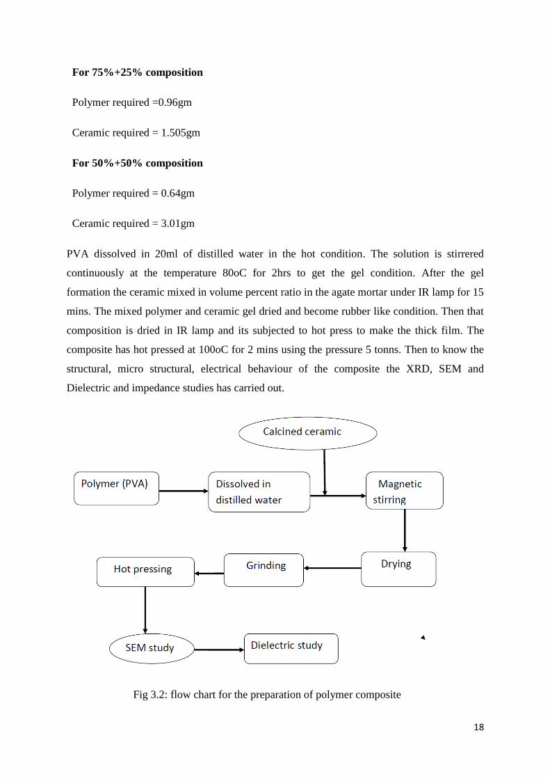
Figure 5.4 shows the variation of the dielectric permittivity with frequency for the
PVA:BYZT (75:25%) polymer electrolyte at different temperatures. From the plots, it is clear
that the permittivity decreases monotonically with increasing frequency and attains a constant
value at higher frequencies. Similar behavior has also been observed in other materials. This
26
is because, for polar materials, the initial value of the dielectric permittivity is high, but as the
frequency of the field is raised the value begins to drop, which could be because the dipoles
are not able to follow the field variation at higher frequencies, as well as polarization effects.
The low-frequency dispersion region is attributed to charge accumulation at the electrode–
electrolyte interface. At higher frequencies, the periodic reversal of the electric field occurs
so fast that there is no excess ion diffusion in the direction of the field. Hence, the dielectric
permittivity (ε′) decreases with increasing frequency in all of the samples. the measured
series capacitance, Cs is given by
where C′ is the frequency-independent capacitance, R is the temperature-dependent
resistance, and ω is 2πf. The above equation predicts that Cs should be decrease with
increasing frequency f, eventually tending to a constant value C′ for all temperatures and any
given frequency. Since the permittivity is directly proportional to Cs,
Cs = εA/d
where d is the thickness of the film and A is the effective area (contact area of the electrode
during the experiment), the permittivity should decrease with increasing frequency
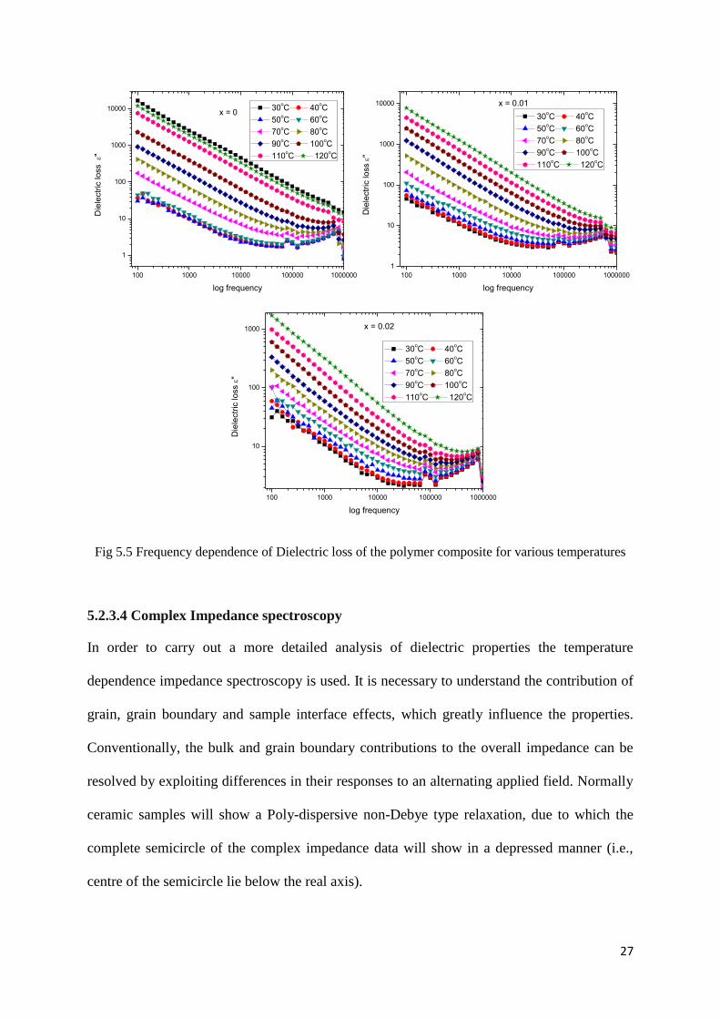
5.2.3.3 Frequency dependence of dielectric loss
In all the compositions, the loss peaks shows high values in low and high frequencies and the
small down curve in the middle of the frequencies. The down curve is shifted to higher
frequencies with increasing temperature and it disappears in high temperature for x=0
composition. For doped compositions, the down curves are in the experimental frequency
range. This curve like structure may give two relaxation process in low frequency side and
high frequency side beyond the experimental limit as reported earlier sengwa and choudhary
[33].
27
100 1000 10000 100000 1000000
1
10
100
1000
10000
30oC 40
oC
50oC 60
oC
70oC 80
oC
90oC 100
oC
110oC 120
oC
Die
lectr
ic lo
ss "
log frequency
x = 0
100 1000 10000 100000 1000000
1
10
100
1000
10000
30oC 40
oC
50oC 60
oC
70oC 80
oC
90oC 100
oC
110oC 120
oC
Die
lectr
ic lo
ss
"
log frequency
x = 0.01
100 1000 10000 100000 1000000
10
100
1000
30oC 40
oC
50oC 60
oC
70oC 80
oC
90oC 100
oC
110oC 120
oC
Die
lectr
ic lo
ss
"
log frequency
x = 0.02
Fig 5.5 Frequency dependence of Dielectric loss of the polymer composite for various temperatures
5.2.3.4 Complex Impedance spectroscopy
In order to carry out a more detailed analysis of dielectric properties the temperature
dependence impedance spectroscopy is used. It is necessary to understand the contribution of
grain, grain boundary and sample interface effects, which greatly influence the properties.
Conventionally, the bulk and grain boundary contributions to the overall impedance can be
resolved by exploiting differences in their responses to an alternating applied field. Normally
ceramic samples will show a Poly-dispersive non-Debye type relaxation, due to which the
complete semicircle of the complex impedance data will show in a depressed manner (i.e.,
centre of the semicircle lie below the real axis).

28
0.0 0.5 1.0 1.5 2.0 2.5 3.0
0.0
0.2
0.4
0.6
0.8
1.0
1.2
Z"
M
Z' M
x = 0
x = 0.01
x = 0.02
Fig.5.6 Complex impedance plot of polymer composites at 102oC
Fig. 5.6 shows the Nyquist plots (complex impedance spectrum) of polymer composite at
different temperatures. This plot shows the transport response function. Characteristically,
one semicircular arcs have been observed at low temperatures and second circles slowly
formed for high temperatures. At 120oC, complete two semicircles are formed and the low
frequency semicircle is considered due to the grain boundary (blocking core) whereas the
higher frequency semicircle depicts the bulk effect. This bulk effect arises due to the parallel
combination of bulk resistance (Rb) and bulk capacitance (Cb) of polymer composite. This
plot indicates the changes in grain boundary resistance at elevated temperatures representing
the role of grain boundaries in electrical conduction process of the material. Doped samples
shows the high values of grain and grain boundary resistance compared to the undoped
samples at particular temperature 120oC. In the overall temperature range (fig not shown)
grain boundary resistance decreases with rise in temperature may be due to the lowering of
barrier favoring the increase of mobility of charge carriers that adds to the conduction
process.
29
CHAPTER -6
Conclusion
In this work, we have prepared and studied the perovskite ceramics having the general
chemical formulaBa1-xY2x/3Zr0.1Ti0.9O3 , and the composite of PVA and BZT. The structural
(XRD), micro structural/morphological and electrical properties of the proposed compounds
have been extensively studied.
Based on our results following conclusions have been drawn.
The polymer composite ferroelectric material is prepared by conventional solid state
reaction method taking PVA as a polymer matrix.
The X-ray diffraction patterns of the Y2+
substituted BZT powders and polymer
composite, it can be clearly seen that for all Y contents single phase BZT compound
has been observed without the presence of any impurity peaks.
SEM micrographs shows that the BYZT particle distribution is homogenous with no
porous in the PVA matrix.
The dielectric study shows that the prepared polymer composite materials have high
dielectric constant value showing ferroelectric behavior.

30
References
[1] Chen F, Chu C, He J, Yang Y, Lin J. Organic thin-film transistors with nanocomposite
dielectric gate insulator. Appl Phys Lett 2004;85(15):3295–7.
[2] Rao Y, Ogitani S, Kohl P, Wong CP. Novel polymer–ceramic nanocomposite based on
high dielectric constant epoxy formula for embedded capacitor application. J Appl Polym Sci
2002;83(5):1084–90
[3] P. Kantha, K. Pengpat, P. Jarupoom, U. Intatha, G. Rujijanagul, T. Tunkasiri, Curr. Appl.
Phys. 9 (2009) 460.
[4] C. Peng, J.F. Li, W. Gong, Mater. Lett. 59 (2005) 1576.
[5] D. Lin, K.W. Kwok, H.L.W. Chan, Mater. Chem. Phys. 109 (2008) 455.
[6] H. Maiwa, Jpn. J. Appl. Phys. 46 (2007) 7013.
[7] Z. Zhang, J. Jia, H. Yang, C. Chen, H. Sun, X. Hu, D. Yang, J. Mater. Sci. 43 (2008)
1501.
[8] Z. Chen, J. Hu, Ceram. Inter. 35 (2009) 111.
[9] M.Z.C. Hu, V. Kurian, E.A. Payzant, C.J. Rawn, R.D. Hunt, Powder Technol. 110 (2000)
2.
[10] Z. Chen, A. Shui, Z. Lu, P. Liu, J. Ceram. Soc. Japan 114 (2006) 857.
[11] T. Maiti, R. Guo, A.S. Bhalla, J. Am. Ceram. Soc. 91 (2008) 1769.
[12] J. Cui, G. Dong, Y. Wang, J. Du, J. Mater. Sci: Mater. Electron 20 (2009) 473.
[13] J. Zhang, J. Zhai, X. Chou, J. Shao, X. Lu, X. Yao, Act. Mater. 57 (2009) 4491.
[14] M. Makimoto, S. Yamashita, Microwave Resonators and Filters for Wireless. Springer,
2001, (Chapter 1), pp. 5.
[15] M.T. Sebastian, Dielectric Materials for Wireless Communication. Elsevier, 2008,
(Chapter 3), pp. 58.

31
[16] H. Khemakhem, A. Simon, R. von der Mhll, J. Ravez, J. Phys.: Condens. Matter 12
(2000) 5951.
[17] A. Simon, J. Ravez, Solid State Sci. 5 (2004) 1459.
[18] T. Tsurumi, Y. Yamamoto, H. Kakemoto, S. Wada, H. Chazono, H. Kishi, J. Mater.Res.
17 (2002) 755.
[19] X. Chou, J. Zhai, J. Sun, X. Yao, Ceram. Intern. 34 (2008) 911.
[20] C. Fu, F. Pan, W. Cai, X. Deng, X. Liu, Mater. Scie. Poland 27 (2009) 891.
[21] A. Liu, J. Xue, X. Meng, J. Sun, Z. Huang, J. Chu, Appl. Surf. Sci. 254 (2008) 5660.
[22] L.S. Cavalcante, M. Anicete-Santos, J.C. Sczancoski, L.G.P. Simões, M.R.M.
C. Santos, J.A. Varela, P.S. Pizani, E. Longo, J. Phys. Chem. Solids 69 (2008) 1782.
[23] L.S. Cavalcante, M.F.C. Gurgel, A.Z. Simões, E. Longo, J.A. Varela, M.R. Joya, P.S.
Pizani, Appl. Phys. Lett. 90 (2007) 011901.
[24] S.K. Rout, L.S. Cavalcante, J.C. Sczancoski, T. Badapanda, S. Panigrahi, M. Siu Li, E.
Longo, Physica B 404 (2009) 3341.
[25] L.S. Cavalcante, J.C. Sczancoski, F.S. De Vicente, M.T. Frabbro, M. Siu Li, J.A. Varela,
E. Longo, J. SoleGel Sci. Technol. 49 (2009) 35.
[26] Mehendru, P.C., K. Pathak, K. Jain, P. Mehendru,Phys. 1997. Stat. Sol. 1(42): 403.
[27] Shinka, H.C., I.M. Talwar and A.P. Srivastava, 1989. Thin Solid Films, 82: 229.
[28] Bassler, H., 1984. Phil. Mag. B., 50: 347.
[29] Das-Gupta DK, Zhang S. Non polar polymer/ferro and antiferroelectric ceramic
composite films for high energy storageapplications. Ferroelectrics 1992;134:71–7.
[30] Y. Rao, J. Yue, C.P. Wong, Proc. 51st IEEE Conf. Electronic Component Technology,
5th May–6th June, 2001, p. 1408.
[31] C.K. Chiang, R. Popielarz, Ferroelectrics 275 (2002) 1.

32
[32] L. Ramajo, M. Reboredo, M. Castro, Composites Part A 36 (2005) 1267.
[33] Badapanda et al., Materials Chemistry and Physics 121 (2010) 147–153
[34] Sengwa and Choudhary, eXPRESS Polymer Letters. 4 (2009) 559.
Top Related