


Languages
Pages
Legal


SUPERVISOR’S DECLARATION
We hereby declare that we have checked this project and in our opinion this project is
satisfactory in terms of scope and quality for the award of the degree of Bachelor of
Mechanical Engineering with Manufacturing
Signature
Name of Supervisor: MR MOHD RASHIDI MAAROF
Position: LECTURER
Date: 05 NOVEMBER 2008
Signature
Name of Panel: MR LEE GIOK CHUI, smp, kmn
Position: LECTURER
Date: 05 NOVEMBER 2008
STUDENT’S DECLARATION
I hereby declare that the work in this thesis is my own except for quotations and
summaries which have been duly acknowledged. The thesis has not been accepted for
any degree and is not concurrently submitted for award of other degree.
Signature
Name: NOORSAKINAH BINTI SHAFIE
ID Number: ME05012
Date: 05 NOVEMBER 2008
ABSTRACT
Injection molding process is the predominant method for producing plastic parts.
Injection molded parts like handset casing are best designed through use of injection
molding computer simulation because it can save the time and cost. The development of
handset casing needs the optimum manufacturability parameters to maximize the quality
of the products at lowest cost and highest productivity. There are many defects occurs at
finished products when the parameters not defined precisely. This project is to
investigate and defined the optimum manufacturing parameters of handset casing using
a computer simulation. After reverse engineering of the selected product, the
manufacturability parameters will be determined after the properties of product was
determined. The properties of the products and manufacturability of the product will be
defined using CAE tools and Moldflow Plastic Insight (MPI).

ABSTRAK
Proses suntikan acuan adalah lebih menonjol untuk penghasilan produk plastik. Produk
suntikan acuan seperti bekas telefon bimbit adalah terbaik direka melalui simulasi
computer suntikan acuan kerana menjimatkan masa dan kos. Pembangunan bekas
telefon bimbit memerlukan had-had pembuatan yang optimum untuk meningkatkan
kualiti pada kos yang rendah dan produktiviti terbanyak. Banyak kecacatan berlaku pada
produk siap kerana had-had tidak ditakrifkan secara tepat. Projek ini bertujuan
menyiasat dan mentakrifkan had-had pembuatanyang optimum melalui simulasi
komputer. Selepas melakukan pembalikan kejuruteraan pada produk terpilih, had-had
pembuatan akan dikenalpasti. Sifat-sifat produk akan dikenal pasti melalui kejuruteraan
bantuan computer (CAE) seperti Moldflow Plastic Insight.
ACKNOWLEDGEMENT
Grateful sense goes to Allah, The Most Beneficent and The Most Merciful on
His blessing until this thesis produced properly. With a deep sense of gratitude I
would like to express my sincere thanks to my supervisor, En Mohd Rashidi Maarof
for his attention to guide me on doing this project thesis as well. Thank you too to
other lecturers and staffs who help me in this project.
I am appreciates my parents supports, my brothers and my friends who involved
during this project done. Thanks a lot. To mother and father, your pray is very
meaningful to my life.
I had tried my best to apply the knowledge that you delivered and I hope this can show
my full commitment about the project. I am also happy to present everybody who ever
involved in one way or another, made significant contributions to various process of this
project. I hope I can learn something from this project and everybody can understand all
the input inside this thesis.

TABLE OF CONTENTS
Page
SUPERVISOR’S DECLARATION ii
STUDENT’S DECLARATION iii
ACKNOWLEDGEMENTS iv
ABSTRACT v
ABSTRAK vi
TABLE OF CONTENTS vii
LIST OF TABLES x
LIST OF FIGURES xi
CHAPTER 1 INTRODUCTION
1.1 Introduction 1
1.3 Problem Statement 2
1.3 The Objectives of the Research 2
1.4 Scope of Work 2

CHAPTER 2 LITERATURE REVIEW
2.1 Introduction 3
2.2 Reverse Engineering 3
2.2.1 Solidworks 4
2.2.2 AutoCad 4
2.2.3 3D Plotter 4
2.3 Material 5
2.3.1 Acrylonitrile Butadiene Styrene 5
2.3.2 Acrylonitrile Butadiene Stryrene + Polycarbonate 6
2.3.3 Polycarbonate 6
2.4 Injection Molding 7
2.4.1 Thin Wall Molding 7
2.4.2 Runner Layout 8
2.4.3 Undercut 8
2.4.4 Cavity Balancing 9
2.5 Moldflow 9
2.5.1 Gate Location 9
2.5.2 Fill Time 9
2.5.3 Warpage 10
CHAPTER 3 METHODOLOGY
3.1 Flow Chart 11
3.2 Received FYP Title 13
3.3 Literature Review 13
3.4 Methodology 13
3.4.1 Analysis Current Situation 13
3.4.2 Reverse Engineering 15
3.4.3 Moldflow Plastic Insight 18
3.5 Result and Discussion 21
3.6 Conclusion And Recommendation 22
CHAPTER 4 RESULTS AND DISCUSSION
4.1 Introduction 23
4.2 Reverse Engineering 23
4.3 Moldflow Analysis 25
4.3.1Best Gate Location 25
4.3.2 Fill Analysis 26
4.4 Effect of Time Over Injection Pressure 31
4.5 Warpage Analysis 32

4.5.1 Effect of Melting Point 32
4.5.2 Effect of Mold Temperature 33
4.5.3 Effect of Filling Time 34
4.5.4 Effect of Holding Pressure 35
CHAPTER 5 CONCLUSION AND RECOMMENDATIONS
5.1 Conclusion 36
5.2 Recommendation 37
REFERENCES 38
APPENDICES
A- Example of Analysis Log 42
B- Example of Machine Setup 57
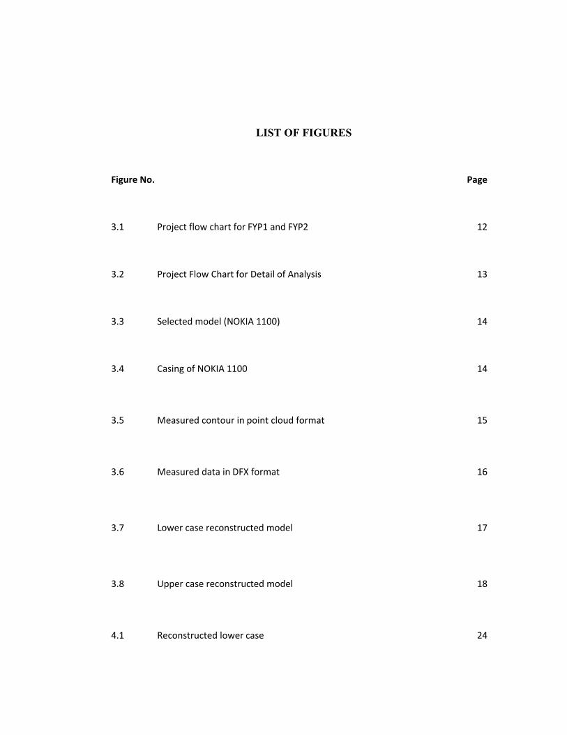
LIST OF FIGURES
Figure No. Page
3.1 Project flow chart for FYP1 and FYP2 12
3.2 Project Flow Chart for Detail of Analysis 13
3.3 Selected model (NOKIA 1100) 14
3.4 Casing of NOKIA 1100 14
3.5 Measured contour in point cloud format 15
3.6 Measured data in DFX format 16
3.7 Lower case reconstructed model 17
3.8 Upper case reconstructed model 18
4.1 Reconstructed lower case 24
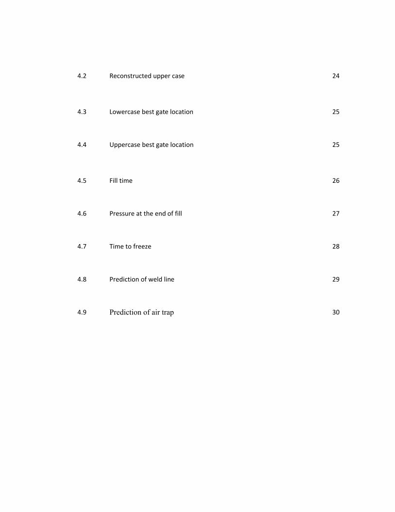
4.2 Reconstructed upper case 24
4.3 Lowercase best gate location 25
4.4 Uppercase best gate location 25
4.5 Fill time 26
4.6 Pressure at the end of fill 27
4.7 Time to freeze 28
4.8 Prediction of weld line 29
4.9 Prediction of air trap 30

CHAPTER 1
INTRODUCTION
1.1 INTRODUCTION
The use of plastic material has grown phenomenally during the last several
decades. Application are continually expanding and include both replacement of parts
made of more traditional material and creation of new products that otherwise would be
impractical, if not impossible to produce without plastics. Handset casing is a one of the
applications of the use of plastic material.(Beaumont,2002)
The injection molding process is the predominant method for producing plastic
parts. It provides significant advantages over many alternative manufacturing methods
use with either plastic material or other competitive materials. This is particular true in
the case of product that is to be produced in large quantity. The injection molding
process offers the ability to produces parts in large volumes, quickly, with precise detail,
excellent repeatability and at minimum cost.
The injection molded parts are best designed through use of injection molding
simulation. These programs provide the unique opportunity to evaluate mold filling,
packing, cooling, product shrinkage, warpage and structural characteristic before a mold
is ever built. The software is useful in simulating and visualizing the performance of the
injection molding process. Thus, the competitive edge between competitors is done at
lowest possible cost.

1.2 PROBLEM STATEMENT
1.2.1 Problem
Plastic injection molding is one of the most important polymer processing in
plastic industry today. However, to produce precise plastic part like handset casing, it
need a high skill in mold making and injection molding machine control. Nonaccurate
parameters will lead to the defects in product or mold. This can affect the productivity
and the production will suffer the high loss.
1.2.2 Solution
To develop a handset casing, there are many manufacturing parameters need to
investigate in order to maximize the quality of the casing at the lowest cost and highest
productivity rate. There are many defects occurs at finished product when it is ejected
from injection mould because the manufacturing parameters was not defined precisely
or at optimum condition.
1.3 OBJECTIVE
To investigate manufacturability of handset casing using computer simulation
1.4 SCOPE OF WORK
(i) Do the reverse engineering of selected product
(ii) Use the CAE tool (Moldflow) to investigate the manufacturing
parameters.
(iii) Recommend improvement design (if any)

CHAPTER 2
LITERATURE REVIEW
2.1 INTRODUCTION
The objection of design concept for an injection –molded thermoplastic part with
a thin shell feature in the computer, communication and consumer electronic product
have more space for the tightly packed components. Therefore, the wall thickness of the
housing parts will reduce to 1mm or less in thickness from the original of 2-3mm in
thickness. [2]
2.2 REVERSE ENGINEERING
While conventional engineering creates a CAD model based on the functional
specifications of a new product, reverse engineering uses a manufactured part to
produce CAD model. [3] Reverse engineering typically starts with measuring a physical
object to reconstruct a CAD model for applications. [4]
The most critical part of reverse engineering is the segmentation process because
it seriously affects the quality of the resulting CAD model. To improve the quality of
segmentation, it is essential to make use of features (sharp edges and symmetry planes).
[4]
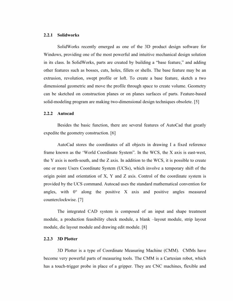
2.2.1 Solidworks
SolidWorks recently emerged as one of the 3D product design software for
Windows, providing one of the most powerful and intuitive mechanical design solution
in its class. In SolidWorks, parts are created by building a “base feature,” and adding
other features such as bosses, cuts, holes, fillets or shells. The base feature may be an
extrusion, revolution, swept profile or loft. To create a base feature, sketch a two
dimensional geometric and move the profile through space to create volume. Geometry
can be sketched on construction planes or on planes surfaces of parts. Feature-based
solid-modeling program are making two-dimensional design techniques obsolete. [5]
2.2.2 Autocad
Besides the basic function, there are several features of AutoCad that greatly
expedite the geometry construction. [6]
AutoCad stores the coordinates of all objects in drawing I a fixed reference
frame known as the ‘World Coordinate System”. In the WCS, the X axis is east-west,
the Y axis is north-south, and the Z axis. In addition to the WCS, it is possible to create
one or more Users Coordinate System (UCSs), which involve a temporary shift of the
origin point and orientation of X, Y and Z axis. Control of the coordinate system is
provided by the UCS command. Autocad uses the standard mathematical convention for
angles, with 0° along the positive X axis and positive angles measured
counterclockwise. [7]
The integrated CAD system is composed of an input and shape treatment
module, a production feasibility check module, a blank –layout module, strip layout
module, die layout module and drawing edit module. [8]
2.2.3 3D Plotter
3D Plotter is a type of Coordinate Measuring Machine (CMM). CMMs have
become very powerful parts of measuring tools. The CMM is a Cartesian robot, which
has a touch-trigger probe in place of a gripper. They are CNC machines, flexible and
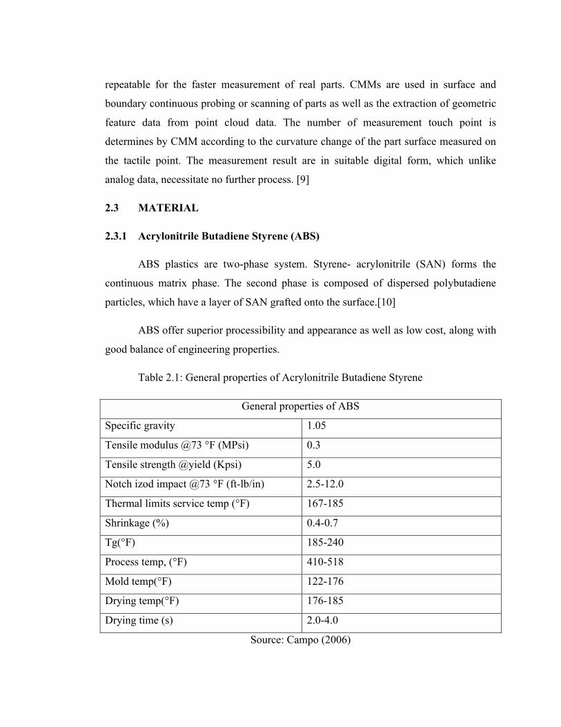
repeatable for the faster measurement of real parts. CMMs are used in surface and
boundary continuous probing or scanning of parts as well as the extraction of geometric
feature data from point cloud data. The number of measurement touch point is
determines by CMM according to the curvature change of the part surface measured on
the tactile point. The measurement result are in suitable digital form, which unlike
analog data, necessitate no further process. [9]
2.3 MATERIAL
2.3.1 Acrylonitrile Butadiene Styrene (ABS)
ABS plastics are two-phase system. Styrene- acrylonitrile (SAN) forms the
continuous matrix phase. The second phase is composed of dispersed polybutadiene
particles, which have a layer of SAN grafted onto the surface.[10]
ABS offer superior processibility and appearance as well as low cost, along with
good balance of engineering properties.
Table 2.1: General properties of Acrylonitrile Butadiene Styrene
General properties of ABS
Specific gravity 1.05
Tensile modulus @73 °F (MPsi) 0.3
Tensile strength @yield (Kpsi) 5.0
Notch izod impact @73 °F (ft-lb/in) 2.5-12.0
Thermal limits service temp (°F) 167-185
Shrinkage (%) 0.4-0.7
Tg(°F) 185-240
Process temp, (°F) 410-518
Mold temp(°F) 122-176
Drying temp(°F) 176-185
Drying time (s) 2.0-4.0
Source: Campo (2006)

2.3.2 Polycarbonate + Acrylonitrile butadiene styrene blend (PC+ ABS)
A compounded blend of polycarbonate and ABS. the PC contribute impact and
heat distortion resistance, while the ABS contributes processability and chemical stress
resistance and cost reduction below PC. [10]
Table 2.2: General properties of Polycarbonate+ Acrylonitrile Butadiene Styrene
General properties of PC+ABS
Specific gravity 1.07
Tensile modulus @73 °F (MPsi) 0.8
Tensile strength @yield (Kpsi) 9.8
Notch izod impact @73 °F (ft-lb/in) 3.4-6.4
Thermal limits service temp (°F) 180-206
Shrinkage (%) 0.3-0.5
Tg(°F) 210-235
Process temp, (°F) 460-541
Mold temp, (°F) 154-193
Drying temp, (°F) 192-216
Drying time,(s) 2.0-4.0
Source: Campo (2006)
2.3.3 Polycarbonate (PC)
Polycarbonate is an amorphous engineering thermoplastic material with
exceptional high impact strength, transparency, high temperature resistance and
dimensional stability. Polycarbonate has high corona resistance and insulation resistance
properties, as well as a dielectric constant that is independent of temperature [10]

Table 2.3: General properties of Polycarbonate
General properties of PC
Specific gravity 1.40
Tensile modulus @73 °F (MPsi) 1.25
Tensile strength @yield (Kpsi) 19
Notch izod impact @73 °F (ft-lb/in) 1.7-3.0
Thermal limits service temp (°F) 220-265
Shrinkage (%) 0.15-0.6
Tg(°F) 293-300
Process temp, (°F) 430-620
Mold temp, (°F) 175-220
Drying temp, (°F) 250-260
Drying time, (s) 2.0-4.0
Source: Campo (2006)
2.4 INJECTION MOLDING
2.4.1 Thin wall molding
Thin wall molding is a high speed, high pressure injection molding process for
producing parts with a nominal wall thickness less than 1.2mm or flow-length-to-wall-
thickness ratios ranging from 100:1 to 150:1 or more. This process becomes
increasingly important due to the economic advantages of using thin walls and the
unpredicted growth of portable electronic and communication devices that require
thinner, smaller and lighter housings. [11]
In thin wall molding, the packing pressure is the most influential factor. The
second is mold temperature, followed by the melt temperature and the packing time. The
less influential factors are the gate dimension and filling time. [12]
2.4.2 Runner layout
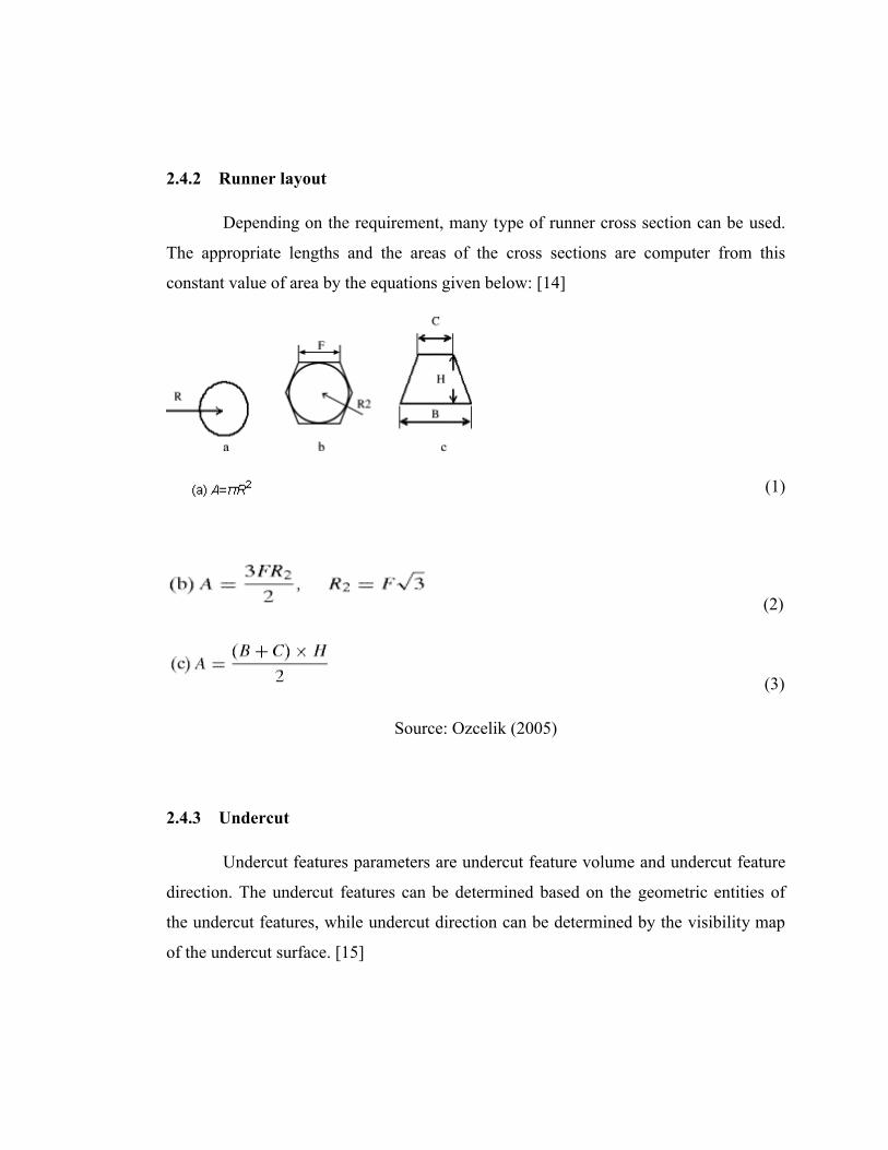
Depending on the requirement, many type of runner cross section can be used.
The appropriate lengths and the areas of the cross sections are computer from this
constant value of area by the equations given below: [14]
(1)
(2)
(3)
Source: Ozcelik (2005)
2.4.3 Undercut
Undercut features parameters are undercut feature volume and undercut feature
direction. The undercut features can be determined based on the geometric entities of
the undercut features, while undercut direction can be determined by the visibility map
of the undercut surface. [15]

2.4.4 Cavity balancing
Cavity balancing is still one area that depends heavily on human interaction and
input. The primary aim of cavity balancing is to fulfill the design criteria whereby the
flow front of the plastic melt reaches the boundary or extremities of the mold at about
the same with equal pressure. Balance flow is critical to the quality of the final product,
as unbalanced flow during filling often leads to warping. [16]
2.5 MOLDFLOW
Moldflow Plastic Insight (MPI) software is an integrated suite of analysis tools
that utilize CAD files and apply advanced Finite Element Analysis (FEA) techniques to
quickly and easily enable a virtual design environment before initiating mold
construction.
2.5.1 Gate location
The placement of gate in an injection mold is one of the most important
variables of the total mold design. The quality of the molded part is greatly affected by
the gate location, because it influences the manner in which the plastic flows into the
mold cavity. Some defects, such as overpack and warpage can be effectively controlled
by the gate location. Therefore, product quality can be greatly improved by having an
optimum gate location. [17]Proper gate location leads to a better resin flow and shorter
hesitation time. [18]
The success of filling and curing stages in liquid composite (LCM) depends in
many variables such as location of gates and vents, temperature distribution, flow rate,
injection pressure, etc. the process performance index based on gate-distance of the
resin located on the flow front at different time steps. A good process should have short
filling time and a vent –oriented flow with a desired resign flow pattern. At a given time
step, the distances from the nodes located on the resin flow front to the outlet are
associated with the quality of the filling process. The standard deviation of those
distances is used to evaluate the shape of the flow front (the smaller the better). [19]

2.5.2 Fill time
The fill time represent the behavior of the melt polymer at regular intervals.
Thermoplastic flow inside the mold using calculates a flow front that grows from
interconnecting nodes at each element, starting at the injection nodes.[20]
2.5.3 Warpage
Warpage is the result of differential shrinkage. If the shrinkage of a material
were completely isotropic with respect to thickness, flow direction and distance and
pack pressure, plastic part would not warp. [21]
The small packing pressure can lead to high warpage value. The increasing of
melt temperature can causes a decreasing on warpage.[22]
Mold thicknesses have an effect on the warpage of the part. The graph shows
that the thicker package reduces warpage, because of the rigidity of the package
increases. [23] The residual warpage on part can be decreased using an additional film
on top of the package or by increasing the mold thickness.[24]
Thermal warpage resulting from unbalanced cooling in a flat plate of amorphous
polymer. The thinnest part warps the greatest amount because its relatively small second
moment of area in bending. The warpage is predicted from the temperature difference
between the upper and lower surfaces, the temperature distribution, flow-induced shear
stress, shrinkage, and anisotropic mechanical properties caused by fiber orientation.
Higher shear stress on the material and more molecular orientation will be expected
contribute to warpage. The higher L: T (length to thickness) ratio will also result in
more warpage[25]

CHAPTER 3
METHODOLOGY
3.1 FLOW CHART/ PROJECT FLOW
Figure3.1: Project flow chart for FYP1 and FYP2

Figure 3.2: Project Flow Chart for Detail of Analysis

3.2 RECEIVED FYP TITLE
After received the title of final year project, my supervisor and I make discussion
about it. We discuss about problem statement, objective and scopes of work of this
project.
3.3 LITERATURE REVIEW
After discuss about the project detail, I make a literature review. I got the
information about the project in journal, book and others project.
3.4 METHODOLOGY
Methodology is a important element in a project where it specifically describes
the method to be used in the project. It is also can be a guideline to ensure we are
following the project flow that we have planned at the beginning. Methodology also will
help in order to make sure that the research run smoothly until we get the result and
achieve the project objective.
3.4.1 Analysis Current Situation
Before getting start to make analysis, I make some review on current situation
like the material that commonly use in production of handset casing, the latest
innovation and the problem that being face by selected model. I choose NOKIA 1100
casing as my model.
Top Related