


Languages
Pages
Legal


SUMMER INTERNSHIP
DEPATMENT OF ELECTRICAL ENGINEERING
26TH MAY TO 11TH JUNE
AT
SHAKSHI TRANSFORMERS PVT.LTD
H.O.D
VISITED STUDENT
PROF.NITI DESAI MALAV PARMAR
(170600109031)

CONTENT
1. ACKNOWLEDGEMENT
2. INFORMATION
3. PURPOSE OF VISIT
4. WHAT WE OBSERVED
5. CONCLUSION
ACKNOWLEDGEMENT
I’M THANKFUL TO DIRECTOR AS WELL AS PRINCIPAL, AND H O D
PROF.NITI DESAI AND OUR FACUILTIES WHO GIVE US A GREAT GUIDANCE
REGARDING TRANING AND INSTRUCT US THE IMPORTANCE OF TRAINING
IN ELECTRICAL FILD. SO I DECIDED TO TAKE TRAINING IN SHAKSHI
TRANSFORMERS PVT .LTD.
I’M ESPECIALLY THANKFUL TO RESPECTED OWNER (MR. TARUN BHAI ) OF
THIS UNIT BECAUSE THEY GRANTED PERMISSION FOR TAKING VISIT AND
ASSISTANT ENGINEERS OF THIS UNIT (MR. ROMILBHAI),(MR. TANMAY
BHAI)
WHO GAVE THE PROPER GUIDANCE AND GAVE PRACTICAL BASED
APPROACH
What is a transformer?
A transformer is an electrical device which , by the principle of electromagnetic
induction,

Transfer electrical energy from one electric circuit to another, without changing the
frequency. The energy transfer usually take place with a change of voltage and current.
Transformer either
Increases or decreases AC voltage.
There are many different type of transformer is use today. This resource will take a closer look at power
Transformer, Auto transformers, Distribution Transformer , instrument Transformer
,isolation Transformer, Potential Transformer and current Transformers.
Different parts of transformers:
Core, Winding, Insulation, Tank, Terminal and Bushings, Transformer oil, Oil
conservator, Breather, Radiators and fans, Explosion vent , Tap changers.
1.CORE
The transformer core provides a magnetic path to channel flux. The core is constructed of
numerous thin strips of grain-oriented silicone steel, called laminations, which are

electrically isolated (yet still magnetically coupled) from each other by thin coatings of
insulating material. This is important to reduce the no-load losses of the transformer. The
core is a source of heat in the transformer and as a core increases in size, cooling ducts
within the core may become necessary. Problems such as short-circuited core laminations
will result in increased losses and possibly overheating of the transformer core.
The core is insulated from the grounded mechanical structures that hold it together and
support it and is then intentionally grounded to a single point. Larger transformer cores that
have multiple core sections isolated from one another by cooling ducts may implement core
jumpers to bond the sections of the core together and a single lead to solidly connect the bonded group to earth.
2.winding
The windings are used for core type transformers. • Each limb is wound with a group of coils
consisting of both primary and secondary turns which may be concentric cylinders. • The l.v.
winding is placed next to the core and h.v. winding on the outside. • But the two windings can be sub-divided, and interlaced with high tension and low tension section alternately to
reduce leakage reactance.

There are different types of windings used for different kinds of applications and
arrangements. Windings are the conductors wrapped in various forms like helical, disc, cylindrical, crossover which generates MMF that is carried by the core to other windings for
having the different levels of voltages. Mainly there are two types of transformer:
1. Core Type Transformer.
2. Sell Type Transformer.
Core Type Transformer:--In core type, we wrap the primary, and secondary windings on the outside limbs, and in shell type, we place the primary and secondary windings on the inner limbs. We use concentric type windings in core type transformer. We place low voltage winding
near to the core. However, to reduce leakage reactance, windings can be interlaced. Winding
for core type depends on many factors like current rating, short circuit withstands capacity,
the limit of temperature rise, impedance, surge voltage, transport facilities, etc.


LV winding Hv winding

3.Insulation
The primary and secondary coils of a transformer are the key
components in performing its basic function of transforming voltage
and current. Materials are used to insulate the primary and secondary
coils
In transformers, in addition to the primary and secondary coils, there
are several other important components and accessories. The insulating material is one of the most critical components of a transformer. •
Major insulation: – between core and low-voltage (LV) winding; – between LV and high-voltage (HV) winding;
– between top and bottom of winding and yoke; – between HV and tank; – bushings.
• Minor insulation: – between conductors;
– between turns;
– between layers;
– between laminations;
– between joints and connections.
Tank
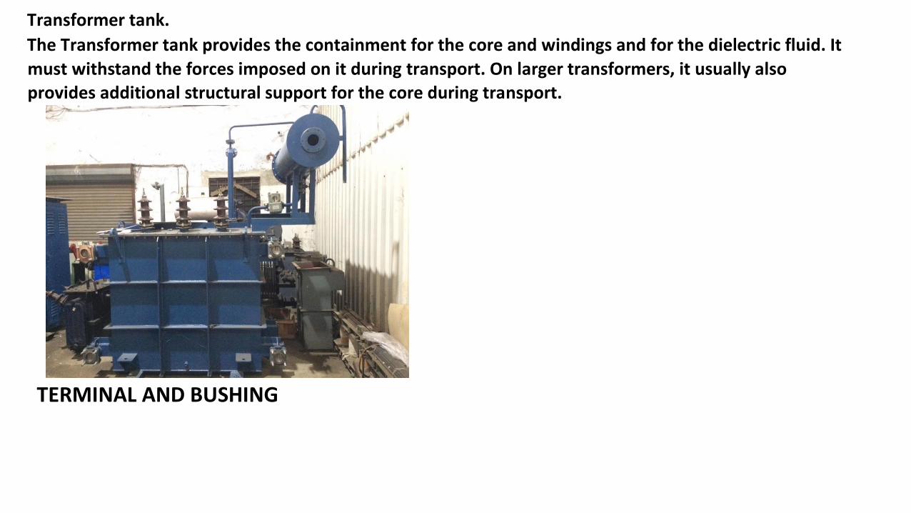
Transformer tank.
The Transformer tank provides the containment for the core and windings and for the dielectric fluid. It
must withstand the forces imposed on it during transport. On larger transformers, it usually also provides additional structural support for the core during transport.
TERMINAL AND BUSHING

A bushing must be designed to withstand the electrical field
strength produced in the insulation, when any earthed material is present. As the strength of the electrical field increases, leakage
paths may develop within the insulation. If the energy of the leakage path overcomes the dielectric strength of the insulation,
it may puncture the insulation and allow the electrical energy to conduct to the nearest earthed material causing burning and
arcing.
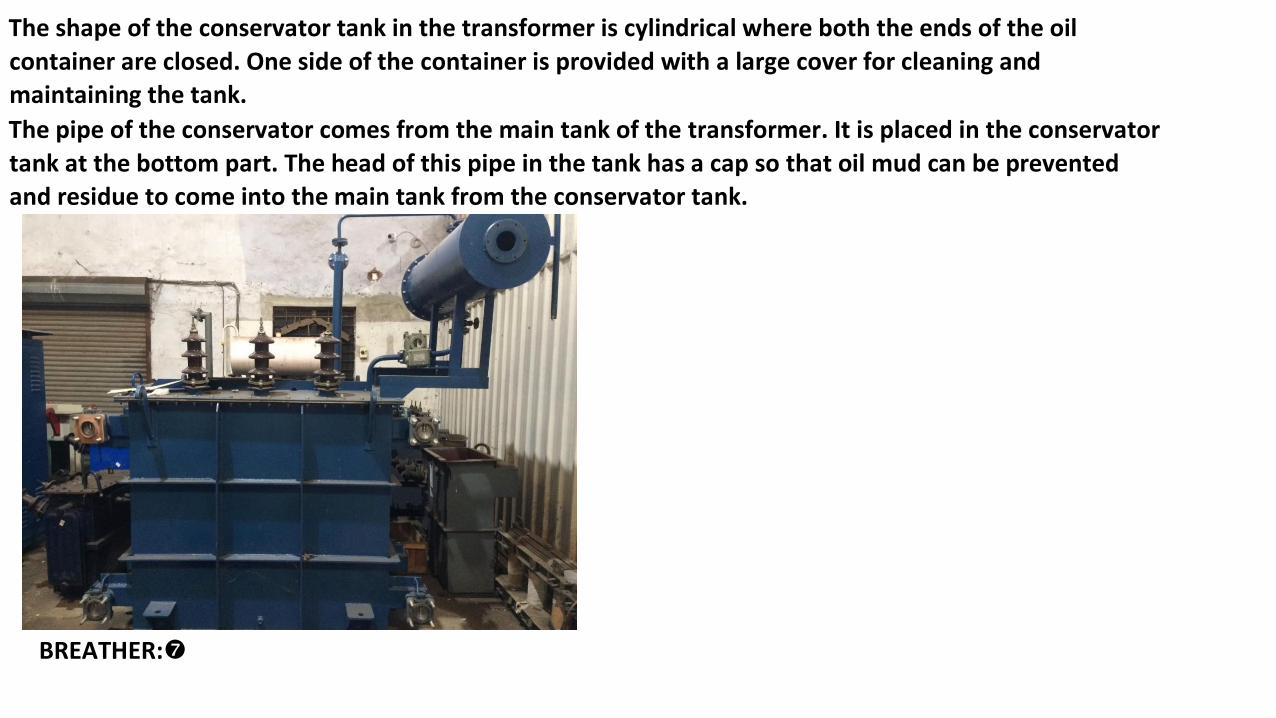
OIL CONSERVATOR:
The shape of the conservator tank in the transformer is cylindrical
where both the ends of the oil container are closed. One side of the
container is provided with a large cover for cleaning and
maintaining the tank.
The pipe of the conservator comes from the main tank of the transformer. It is placed in the conservator
tank at the bottom part. The head of this pipe in the tank has a cap so that oil mud can be prevented
and residue to come into the main tank from the conservator tank.
OIL CONSERVATOR:
The shape of the conservator tank in the transformer is cylindrical where both the ends of the oil
container are closed. One side of the container is provided with a large cover for cleaning and maintaining the tank.
The pipe of the conservator comes from the main tank of the transformer. It is placed in the conservator
tank at the bottom part. The head of this pipe in the tank has a cap so that oil mud can be prevented
and residue to come into the main tank from the conservator tank.
BREATHER:

Transformer Breather Helps to Prevent Atmospheric Moisture and Reduce Maintenance Costs.
During the breathing cycle of a transformer, it is crucial to prevent atmospheric moisture from entering the transformer, which can contaminate the oil.
RADIATOR: When a transformer is loaded, the current starts flowing through it's
windings. Due to this flowing of electric current, heat is produced in the
windings, this heat ultimately rises the temperature of transformer oil. The radiator of transformer accelerates the cooling rate
of transformer TAP-CHANGER:

A tap changer is a mechanism in transformers which allows for variable turn ratios to
be selected in distinct steps. This is done by connecting to a number of access points known as taps along either the primary or secondary winding.
Tap changers exist in two primary types, no-load tap changers (NLTC), which must be
de-energized before the turn ratio is adjusted, and on-load tap changers (OLTC),
which may adjust their turn ratio during operation. The tap selection on any tap
changer may be made via an automatic system, as is often the case for OLTC, or a
manual tap changer, which is more common for NLTC. Automatic tap changers can be
placed on a lower or higher voltage winding, but for high-power generation and
transmission applications, automatic tap changers are often placed on the
higher voltage (lower current) transformer winding for easy access and to
minimize the current load during operation.
Explosion vent:
The explosion vent is used to expel boiling oil in the transformer during heavy internal faults in order to avoid the explosion of the transformer.
During heavy faults, the oil rushes out of the vent. The level of the explosion vent is normally maintained above the level of the
conservatory tank.

FLOW CHART OF TRANSFORMER :

TESTING OF
TRANSFORMER :
1.RATIO TEST
2.FULL LOAD TEST
3.NO LOAD TEST
4.HIGH VOLTAGE
TEST
1. RATIO TEST:
Power transformer turns ratio test is an AC low voltage test which determines the ratio of the high
voltage winding to all other windings at no-load.
Ratio measurements are conducted on all tap positions and calculated by dividing the induced voltage reading into the applied voltage value.

FULL LOAD TEST:
The Full Load Test Method (FLT) uses a variable speed drive motor, simulating a rider pedalling a
front chain ring. A torque load (DC generator) is applied to the rear axle to simulate the load at
the rear wheel.
During operation, both sensors measure the torque on their respective shafts.

NO LOAD TEST :
No-load tests are tests that apply rated voltage in the primary side at the no-load state of the
secondary side. Current only flows to the primary side in the no-load test, but this current causes
excitation and iron loss of the iron core.
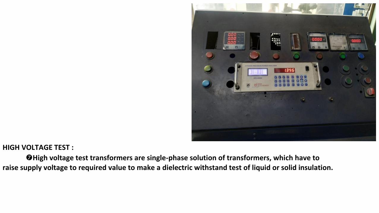
HIGH VOLTAGE TEST :
High voltage test transformers are single-phase solution of transformers, which have to raise supply voltage to required value to make a dielectric withstand test of liquid or solid insulation.
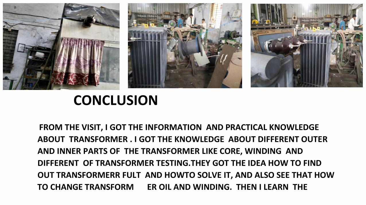
CONCLUSION
FROM THE VISIT, I GOT THE INFORMATION AND PRACTICAL KNOWLEDGE
ABOUT TRANSFORMER . I GOT THE KNOWLEDGE ABOUT DIFFERENT OUTER
AND INNER PARTS OF THE TRANSFORMER LIKE CORE, WINDING AND
DIFFERENT OF TRANSFORMER TESTING.THEY GOT THE IDEA HOW TO FIND
OUT TRANSFORMERR FULT AND HOWTO SOLVE IT, AND ALSO SEE THAT HOW
TO CHANGE TRANSFORM ER OIL AND WINDING. THEN I LEARN THE

IMPORTANCE TO IMPROVE OF TRANSFORMER EFFICIENCY. THEN AFTER I SEE
THAT HOW TO PURIFY THE TRANSFORMER OIL WITH THE USE OF OIL FILTER THEN WE SEE THAT WINDING PLACED IN CORE THEN CORE IS PUT IN INDUSTRIAL OVER IN 2 TO 3 DAYS.
Top Related