

![[RELO] Drama and EFL Acquisition](https://static.fdocuments.us/doc/165x107/545d2ff5af7959c3098b49c6/relo-drama-and-efl-acquisition.jpg)
![[RELO] Teaching Vocabulary](https://static.fdocuments.us/doc/165x107/54966566b47959ec108b46f7/relo-teaching-vocabulary.jpg)
![[RELO Andes] "Ready-to-go" Activities for ESL Classroom](https://static.fdocuments.us/doc/165x107/55aa84411a28ab3b1c8b46c8/relo-andes-ready-to-go-activities-for-esl-classroom.jpg)
![[RELO] Teaching Through Emotions](https://static.fdocuments.us/doc/165x107/54966574b479599e0c8b4746/relo-teaching-through-emotions.jpg)

![[RELO] American Culture Series: Exploring Frontiers](https://static.fdocuments.us/doc/165x107/55d4b096bb61ebf4748b4597/relo-american-culture-series-exploring-frontiers.jpg)
Languages
Pages
Legal


2A 3A
STANDARDSignal Circular Connectors

5A

5A
A S T A 0 5 5 M R 0 4 1 0 0 0 3 5 0 0 0
Ordering information STANDARD signal circular connectors
HOUSING DESIGNS
ST = PlugSD = Angled plug, rotatableDF = BushingKU = ExtensionEG = Receptacle, straightEW = Receptacle, angledED = Receptacle, angled rotatable
SERIESA = Signal connectors STANDARD
HOUSING SURFACE
A = Nickel platedB = Plastic coveredC = ChromatedD = Chrome plated (black)
INSULATION INSERTS
Component related code,e.g. 055
CONTACT, CONNECTION
M R
CONTACT TYPE
Component related code,e.g. 04
CABLE CLAMPING
Cable diameter related code,e.g. 10
DESIGN VARIATIONS
See table page A27 ff.
PACKAGING
Standard packaging code: 000
All standard connectors are published in this catalog. However, this catalog does not provide customer specifi cdesigns or variations.
If you are looking for an application optimized solution, don´t hesitate to contact us.
Any questions? Please call our technical sales staff – phone +49 (0)9962 20020.
STANDARD
1st. letterM = Male contactF = Female contact
2nd. letterR = CrimpingS = SolderingD = Board soldering

6A 7A
A x x x x x x x x x x x x x 0 0 0
S T
S T
S T
S D
D F
AVAILABLE HOUSING SURFACES:
A = Nickel plated B = Plastic covered D = Chrome plated (black)
Housing designs
Bushing housing
Available housing surfaceA = Nickel plated
Plug housing
If necessary, distance hulls for insulation inserts are automatically supplied with the connectors. A series standard housings are also available in stainless steel fortypical applications in food processing industry
Plug housingPlastic covered version
Plug housingPush-Pull version
Angled plug, rotatable
Available housing surfaceA = Nickel plated
STANDARD
Please add the corresponding code to the ordering information
Note: Distinction between housing designs with identical ordering code, e.g. ST, please see catalog section DESIGN VARIATIONS x x x x (p. A27 ff.)

6A 7A
A x x x x x x x x x x x x x 0 0 0
K U
K U
K U
AVAILABLE HOUSING SURFACES:
A = Nickel plated B = Plastic covered D = Chrome plated (black)
Housing designs
Extension housingincluding vibration protection
Extension housing – plastic coveredincluding vibration protection
Extension housing, central fi xing
including vibration protection
STANDARD

8A 9A
A x x x x x x x x x x x x x 0 0 0
E G E G
AVAILABLE HOUSING SURFACES:
A = Nickel plated D = Chrome plated (black)
Housing designs
Receptacle – straight versionAxial sealing,
including vibration protection
Receptacle – PG 13,5 including sealing andvibration protection
STANDARD
Note: Distinction between housing designs with identical ordering code, e.g. EG, please see catalog section DESIGN VARIATIONS x x x x (p. A27 ff.)

8A 9A
A x x x x x x x x x x x x x 0 0 0
E W E D
E D
AVAILABLE HOUSING SURFACES:
C = Chromated D = Chrome plated (black)
Housing designs
Receptacle – angled, fi xedAxial sealing,
including vibration protection
Receptacle – angled, rotatableAxial sealing,
including vibration protection
STANDARD
Receptacle – angled, rotatablelarge fl ange (28 x 28mm)
Axial sealing, including vibration protection

10A 11A
A x x x x x x x x x x 0 0 0
5 40
5 50
7 107 00
Insulation inserts[8+1], 9 contacts STANDARD
Suitable for housing design
PLUG ANGLED PLUG EXTENSION BUSHING
E type, 9 contactsP type, 9 contacts
3 coding grooves
E type[8+1] contacts
P type[8+1] contacts
Please add the corresponding code to the ordering information
3 coding grooves
3 coding grooves 3 coding grooves

10A 11A
6 60
A x x x x x x x x x x 0 0 0
8 35
7 202 52
Suitable for RECEPTACLES
STRAIGHT PG 13,5 ANGLED ANGLED ROTATABLE
E type, 9 contactsincluding securing clip
P type, 9 contactsincluding securing clip
Insulation inserts[8+1], 9 contacts STANDARD
3 coding grooves
E type, [8+1] contactsincluding securing clip
P type, [8+1] contactsincluding securing clip
Versions – sealed to IP67 – in unplugged condition on request (male contacts only!)
3 coding grooves
3 coding grooves 3 coding grooves

12A 13A
A x x x x x x x x x x 0 0 0
3 323 22
2 00
5 60
Insulation inserts12 contacts STANDARD
P type, 12 contacts
3 coding grooves
P type, 12 contactsCoding pin on Pin 7
P type, 12 contactsCoding pin on Pin 1
P type, 12 contacts5171 version
Suitable for housing design
PLUG ANGLED PLUG EXTENSION BUSHING
3 coding grooves 3 coding grooves
3 coding grooves

12A 13A
A x x x x x x x x x x 0 0 0
0 310 41
2 10
5 70
E type, 12 contacts
Insulation inserts12 contacts STANDARD
3 coding grooves
E type, 12 contactsCoding hole on Pin 7
E type, 12 contactsCoding hole on Pin 1
E type, 12 contacts5171 version
Suitable for housing design
PLUG ANGLED PLUG EXTENSION BUSHING
3 coding grooves 3 coding grooves
3 coding grooves

14A 15A
1 41
A x x x x x x x x x x 0 0 0
4 960 21
5 20
5 064 90
E type, 12 contactsincluding securing clip
P type, 12 contactsincluding securing clip
Insulation inserts12 contacts STANDARD
3 coding grooves
E type, 12 contactsincl. securing clipCoding pin on pin 1
P type, 12 contactsincl. securing clipCoding pin on pin 1
E type, 12 contactsincl. securing clipCoding pin on pin 7
P type, 12 contactsincl. securing clipCoding pin on pin 7
Suitable for RECEPTACLES
STRAIGHT PG 13,5 ANGLED ANGLED ROTATABLEVersions – sealed to IP67 – in unplugged condition on request (male contacts only!)
3 coding grooves
3 coding grooves 3 coding grooves
3 coding grooves 3 coding grooves

14A 15A
3 02
A x x x x x x x x x x 0 0 0
7 30
E type, 12 contacts5171, incl. securing clip
P type, 12 contacts5171, incl. securing clip
Insulation inserts12 contacts STANDARD
3 coding grooves
Suitable for RECEPTACLES
STRAIGHT PG 13,5 ANGLED ANGLED ROTATABLE
3 coding grooves

16A 17A
A x x x x x x x x x x 0 0 0
6 511 05
6 31 6 41
P type, 16 contacts
Insulation inserts12 contacts STANDARD
Coding groove
E type, 16 contactsincluding securing clip
P type, 16 contactsincluding securing clip
E type, 16 contacts
Suitable for housing design
PLUG ANGLED PLUG EXTENSION BUSHING
Suitable for RECEPTACLES
STRAIGHT PG 13,5 ANGLED ANGLED ROTATABLEVersions – sealed to IP67 – in unplugged condition on request (male contacts only!)
Coding groove
Coding groove Coding groove

16A 17A
A x x x x x x x x x x 0 0 0
1 312 72
3 50 3 40
P type, 17 contacts
Insulation inserts17 contacts STANDARD
3 coding grooves
E type, 17 contactsincluding securing clip
P type, 17 contactsincluding securing clip
E type, 17 contacts
Suitable for housing design
PLUG ANGLED PLUG EXTENSION BUSHING
Suitable for RECEPTACLES
STRAIGHT PG 13,5 ANGLED ANGLED ROTATABLEVersions – sealed to IP67 – in unplugged condition on request (male contacts only!)
3 coding grooves
3 coding grooves 3 coding grooves

18A 19A
7 92
A x x x x x x x x x x 0 0 0
7 82
5 955 85
E type, [16+3] contactsincl. grounding spring
P type, [16+3] contactsincl. grounding spring
Insulation inserts[16+3] contacts STANDARD
Suitable for housing design
PLUG ANGLED PLUG EXTENSION BUSHING
Coding groove
E type, [16+3] contactswithout grounding spring
P type, [16+3] contactswithout grounding spring
Coding groove
Coding groove Coding groove

18A 19A
7 83
A x x x x x x x x x x 0 0 0
4 35
6 056 15
E type, [16+3] contactsincl. securing clipand grounding spring
P type, [16+3] contactsincl. securing clipand grounding spring
Insulation inserts[16+3] contacts STANDARD
Suitable for RECEPTACLES
STRAIGHT PG 13,5 ANGLED ANGLED ROTATABLE
Coding groove
E type, [16+3] contactsincl. securing clip,without grounding spring
P type, [16+3] contactsincl. securing clip,without grounding spring
Coding groove
Coding groove Coding groove

20A 21A
A x x x x x x 0 0 0
!
RF 0 1 SF 0 4
RF 1 1 SF 1 3
Suitable for all housing designs and insulation inserts
HC crimping female contact 1,0mmCrimping range: max. 1,0mm2
HC soldering female contact 1,0mmSoldering connection: 1,5mm2
Slit crimping female contact 1,0mmCrimping range: max. 1,0mm2
Slit soldering female contact 1,0mmSoldering connection: 1,5mm2
Please see the following pages to select ordering codes for contact combinations suitable
Insulation inserts [8+1] contacts (8x1 + 1x2mm) or Insulation inserts [16+3] contacts (16x1 + 3x1,5mm)
Female type contacts STANDARD
Please select the corresponding code

20A 21A
A x x x x x x 0 0 0
RM 0 4
RM 8 3
SM 0 6
DM 1 4
Male type contacts STANDARD
Crimping male contact 1,0mmCrimping range: max. 1,0mm2
Soldering male contact 1,0mmSoldering connection: 1,5mm2
Crimping male contact 1,0mmCrimping range: max. 0,2mm2
Board soldering male contact 1,0mmsuitable for receptacle, straight version
Suitable for all housing designs and insulation inserts

22A 23A
A x x x x x x 0 0 0
RF 2 9
SF 3 4
RF 1 0
Female typeContact combinations STANDARD
8x HC crimping female contact 1,0mmCrimping range: max. 1,0mm2
1x Slit crimping femalecontact 2,0mm
Crimping range: max. 2,5mm2
8x Slit crimping female contact 1,0mmCrimping range: max. 1,0mm2
1x Slit crimping femalecontact 2,0mm
Crimping range: max. 2,5mm2
8x Slit soldering femalecontact 1,0mmSoldering conn.: 1,5mm2
1x Slit soldering femalecontact 2,0mm
Soldering conn.: 2,5 mm2
Female contact combinations:Suitable for insulation insert [8+1] contacts P and E types (8x1mm + 1x2mm)

22A 23A
A x x x x x x 0 0 0
RM 1 8
SM 1 9
Male typeContact combinations STANDARD
Male contact combinations:Suitable for insulation insert [8+1] contacts P and E types (8x1mm + 1x2mm)
8x Crimping malecontact 1,0mmCrimp. range: max. 1,0mm2
1x Crimping male contact 2,0mmCrimping range: max. 2,5mm2
8x Soldering malecontact 1,0mmSoldering conn.: 1,5mm2
1x Soldering male contact 2,0mmSoldering connection: 2,5mm2

24A 25A
A x x x x x x 0 0 0
RF 9 2
RF 9 1
Female typeContact combinations STANDARD
16x HC crimping femalecontact 1,0mmCrimp. range: max. 1,0mm2
3x Slit crimpingfemale contact 1,5mm
Crimp. range: max. 1,0mm2
16x Slit crimpingfemale contact 1,0mmCrimp. range: max. 1,0mm2
3x Slit crimpingfemale contact 1,5mm
Crimp. range: max. 1,0mm2
Female contact combinations:Suitable for insulation inserts [16+3] contactsP and E types (16x1mm + 3x1,5mm)

24A 25A
A x x x x x x 0 0 0
RM 9 3
Male typeContact combinations STANDARD
16x Crimping malecontact 1,0mmCrimp. range: max. 1,0mm2
3x Crimping malecontact 1,5mm
Crimp. range: max. 1,0mm2
Male contact combinations:Suitable for insulation inserts [16+3] contacts P and E types (16x1mm + 3x1,5mm)

26A 27A
A x x x x 0 0 0
1 0
1 2
6 0
6 2
6 1
Cable clamping STANDARD
Suitable for housing design
PLUG ANGLED PLUG EXTENSION
STANDARD clampingClamping unit including seal with strain relief, shielding element, clamping ring
Standard cable clamping
Suitable for cable diameter:5,5 – 10,5mm
Please select the correspondingordering code.Note: For all receptacles housingdesigns add „00“
Shielding element
Clamping unit including seal with strain relief
Clamping ring
Standard cable clamping
Suitable for cable diameter:9,0 – 12,0mm
Advanced LAMELLA clamping„Jagged“ clamping unit (improved revolving protection), incl. seal and strain relief, shielding element, clamping ring
Shielding element
Clamping ring
Clamping unit (revolving protection,seal and strain relief)
Lamella type cable clamping
Suitable for cable diameter: 4,5 – 8,5mm
Lamella type cable clamping
Suitable for cable diameter: 6,0 – 10,0mm
Lamella type cable clamping
Suitable for cable diameter: 9,0 – 13,2mm

26A 27A
A 0 0 0
0 30 5
0 30 6
0 40 1
0 40 2
0 40 7
PLUG
Design variations STANDARD
ORDERING CODE SPECIFICATIONSPICTURE AND CODING
Code 1 – Housing code 0° Metal construction
Code 2 –Housing code 80° / 120°
Metal construction
Code 1 – Housing code 0°
Housing plastic covered Clamping ring: Plastic
Code 2 – Housing code 80° / 120°
Housing plastic covered Clamping ring: Plastic
Code 1 – Housing code 0°
Metal construction PUSH-PULL version
Please select the corresponding code to the ordering information
Customer specifi c designs on request

28A 29A
A 0 0 0
0 30 5
0 30 6
ANGLED PLUG
Design variations STANDARD
ORDERING CODE SPECIFICATIONSPICTURE AND CODING
Code 1 – Housing code 0° Metal construction
Code 2 –Housing code 80° / 120°
Metal construction
Customer specifi c designs on request

28A 29A
A 0 0 0
0 00 1
BUSHING
Design variations STANDARD
Code 1 – Housing code 0° Axial sealing
Customer specifi c designs on request
ORDERING CODE SPECIFICATIONSPICTURE AND CODING

30A 31A
0 30 9
A 0 0 0
0 30 5
0 40 1
0 40 0
0 40 2
Code 2 – Housing code 80° / 120°
Metal construction Vibration protection
EXTENSION
Design variations STANDARD
ORDERING CODE SPECIFICATIONSPICTURE AND CODING
Code 1 – Housing code 0°
Metal construction Vibration protection
Code 1 – Housing code 0°
Housing plastic covered Clamping ring: Plastic Vibration protection
Customer specifi c designs on request
Code 1 –Housing code 0°
Metal construction with central fi xing Vibration protection
Code 2 – Housing code 80° / 120°
Housing plastic covered Clamping ring: Plastic Vibration protection
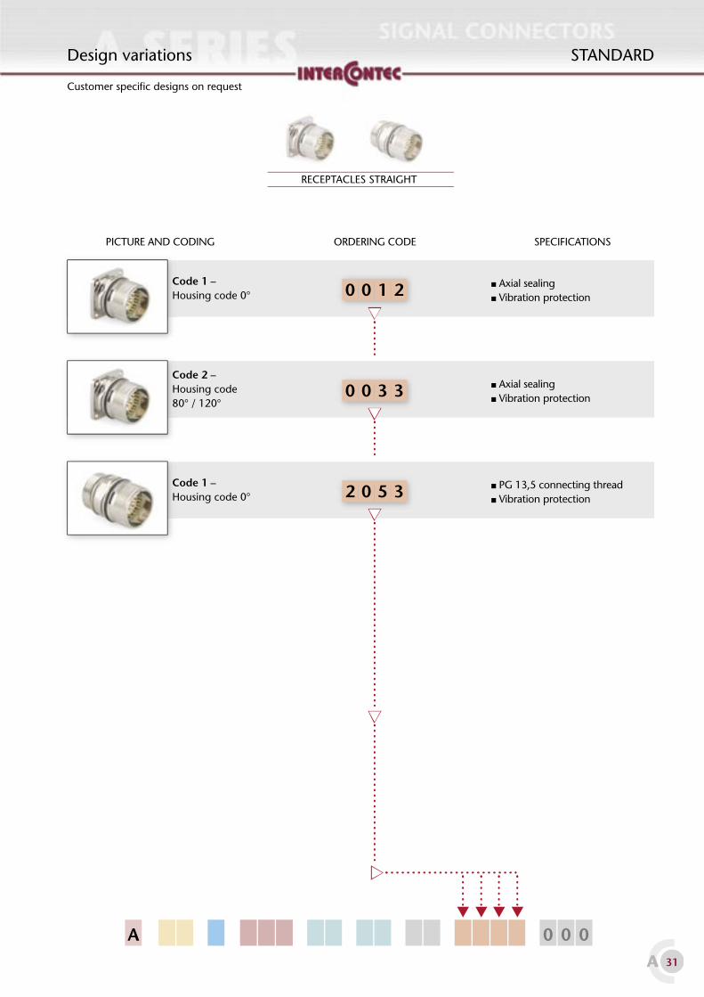
30A 31A
0 52 3
0 30 3
A 0 0 0
0 10 2
Code 1 –Housing code 0°
PG 13,5 connecting thread Vibration protection
Code 2 – Housing code 80° / 120°
Axial sealing Vibration protection
RECEPTACLES STRAIGHT
Design variations STANDARD
Code 1 – Housing code 0°
Axial sealing Vibration protection
Customer specifi c designs on request
ORDERING CODE SPECIFICATIONSPICTURE AND CODING

32A 33A
A 0 0 0
0 10 4
0 10 2
0 10 3
RECEPTACLES ANGLED, FIXED
Design variations STANDARD
ORDERING CODE SPECIFICATIONSPICTURE AND CODING
Code 1 – Housing code 0°
Axial sealing Vibration protection
Code 1 – Housing code 0°
Axial sealing Vibration protection
Customer specifi c designs on request
RECEPTACLES ANGLED, ROTATABLE
ORDERING CODE SPECIFICATIONSPICTURE AND CODING
Code 1 – Housing code 0°
Large fl ange (28 x 28mm) Axial sealing Vibration protection

A
TECHNICAL DATA FOR STANDARD SIGNAL CIRCULAR CONNEC-TORSOperating temperature -20°C to +130°C
Degree of protection IP 66/67 (plugged condition)
ELECTRICAL DATA – [8+1]- TO 12 CONTACT VERSIONSMax. current (max. wire gauge)
max. 10 A
Max. voltage 160 V (AC/DC)
Test voltage (between contacts) 2500 V
Contact resistance < 5 mΩ
Mating cycles > 50
ELECTRICAL DATA – 16-, 17-, [16+3] CONTACT VERSIONSMax. current (max. wire gauge)
max. 9 A
Max. voltage 125 V (AC/DC)
Test voltage (between contacts) 2500 V
Contact resistance < 5 mΩ
Mating cycles > 50
DATA ACCORDING TO VDE 0110/EN61984, PART 6.19.2.2Pollution degree 3
Overvoltage category III
Max. height of operation 2000 m
MATERIALS
HousingZinc die cast / brass
(option: stainless steel)
Connecting nut (some designs) Brass, nickel plated
Insulation inserts PA 6.6/ PBT, UL 94/ V0
Contacts Brass, gold plated
Seals FPM/HNBR
STANDARDTechnical data STANDARD

34A 35A
Drawings STANDARD
PLUGDesign variations0035 / 0036 / 0041 / 0042
EMC shieldingHousing code: Code 1 or code 2
PLUG – PUSH-PULL VERSIONDesign variation 0047
EMC shieldingHousing code: Code 1

34A 35A
Drawings STANDARD
ANGLED PLUG, ROTATABLEDesign variations 0035 / 0036
EMC shieldingHousing code: Code 1 or code 2
BUSHINGDesign variation 0001
Axial sealingHousing code: Code 1

36A 37A
Drawings STANDARD
EXTENSIONDesign variations 0035 / 0039
EMC shieldingVibration protectionHousing code: Code 1 or code 2
EXTENSION WITH CENTRAL FIXINGDesign variation 0040
EMC shieldingVibration protectionHousing code: Code 1
Mounting hole

36A 37A
Drawings STANDARD
RECEPTACLE, STRAIGHTINTEGRATED FLANGEDesign variations 0012 / 0033
Axial sealingVibration protectionHousing code: Code 1 or code 2
RECEPTACLE PG 13,5Design variation 2053
Vibration protectionSealingHousing code: Code 1
Flange dimensions Mounting holes

38A 39A
Ø20 ± 0,2
M2,5
Ø28
19,8
19,8
Ø2,7
25,7
45°
25,7
19,8
Ø28
Ø20 ± 0,2
M2,5
Ø28
19,8
19,8
Ø2,7
25,7
45°
25,7
19,8
Ø28
Drawings STANDARD
Ø20 ± 0,2
RECEPTACLE ANGLED FIXEDDesign variation 0014
Axial sealingVibration protectionHousing code: Code 1
Ø20 ± 0,2
RECEPTACLE ANGLED ROTATABLEDesign variation 0012
Axial sealingVibration protectionHousing code: Code 1
Flange dimensions Mounting holes
Flange dimensions Mounting holes

38A 39A
STANDARDDrawings
RECEPTACLE ANGLED ROTATABLELARGER FLANGE 28 x 28mmDesign variation 0013
Axial sealingVibration protectionHousing code: Code 1
Flange dimensions Mounting holes

40A 41A
Accessories
Metal fl ange2 components, 4x M4 thread,
for optional clamping onto metal housings, including sealing ring
Ordering No.E0.022.02
Plastic protection capsuitable for extensions, receptacles
Ordering No.8A.002.00
Metal protection capAxial sealing, incl. wire cable
suitable for extensions, receptacles
Ordering No.8B.011.01
Metal protection capAxial sealing, incl. wire cable
suitable for plugs
Ordering No.8B.013.01
STANDARD

78A 79A
A 0 0 0
Packaging A SERIES
Standard packaging code: 000
Standard packaging for connectors or connector components: cardboard box (various sizes depending on units packed).
Customer specifi c packaging designs including mounting instructions, e. g. service packs, on request (see picture).

Intercontec Produkt GmbH
Bernrieder Strasse 15
D-94559 Niederwinkling
Tel. +49 (0)9962 - 2002-0
Fax +49 (0)9962 - 200270
Email: [email protected]
http://www.intercontec.biz
© 2002-2003 INTERCONTEC
Technical data may differ or change without notice
INTERCONTEC is not responsibility for data misprints
PDF fi le generated 26/03/03
desi
gn: w
ww
.kat
hede
r.com
Top Related