


Languages
Pages
Legal


AirPreparation
Filter – Filter Pressure Regulator – Pressure RegulatorFN20
-106
-1E
05/
16
StainlessSteel Series
G1/4 - G 1

Filter Type 692 – G1/4 - G1
2
Compressed air filters serve to remove solid and liquid impurities (condensation water, pipe scaling, rust particles) fromthe air in the working place. They protect the following components from dirt and abrasion. This filter has beendeveloped specially for high-demanding applications. Filter with bowl without sight glass, completely made ofstainless steel, therefore extremely robust. Suitable for compressed air, non-toxic gases and liquids.Application area: Chemical industry, mineral oil processing, apparatus engineering.
Accessories
Mounting bracket Dimensions [mm]
Rates of flow [Nl/min]
Mounting bracketSuitable for size ISuitable for size IISuitable for size III
Order No.690-30690-35690-39
Dimensions [mm]
Suitable for G1/2Suitable for G1/4
Standard version:With manual drain valve, filter porosity 50 μm
Order No.Connection thread
G 1/4 G 3/8 G 1/2 G 3/4 G 1692.221 692.231 - - -- - 692.261 - -- - - 692.281 692.291
SizeIIIIII
Suitable for size III
692.021
Size I (G 1/4) Size II (G 1/2) Size III (G 1)
Order key for all variants:692.x x x
1 50 μm 2 25 μm3 5 μm
2 G 1/4 size I3 G 3/8
6 G 1/2 size II8 G 3/4 size III9 G 1
0 without drain valve2 manual drain valve6 External automatic drain valve (stainless steel)
filter porosity
for example:692.221= with manual drain valve,
G 1/4 with 50 μm
Technical data Size I II III
Connection thread G 1/4 G 3/8 G 1/2 G 3/4 G 1Nominal rates of flow (Nl/min)* 2500 4000 10000Media compressed air, non-toxic gases, liquidsFilter porosity 5, 25 or 50 μmMax. pre-pressure (p1) 60 barTemperature ranges with NBR sealings -20 °C - +80 °C
with EPDM sealings (optionally) -45 °C - +80 °Cwith silicone sealings (optionally) -60 °C - +200 °C
Drain of condensate manually operated drain valve / external automatic drain valve (stainless steel)Bowl capacity 0,11 lMaterials - Body/bowl/inner parts stainless steel No. 1.4404 (AISI 316L)
- Sealings NBR (for EPDM and silicone please indicate when ordering)Weight (kg) 1,6 2,3 3,3
* measured at 10 bar, pre-pressure (p1) and Δp = 1 bar
Size I II III
Connectionthread
G 1/4 ,G 3/8
G 1/2 G 3/4, G 1
A 112 128 145
B 62 68 114
C 95 114 123
D G 1/4, G 3/8 G 1/2 G 1, G 3/4
E 62 68 88
F 20 22 36
H 28 32 34
Δp (bar)Δp (bar)Δp (bar)
2500
5000
7500
1000
0
1250
0
1500
0
500
1000
1500
2000
2500
3000
3500
4000
Q (Nl/min) Q (Nl/min) Q (Nl/min)

Filter pressure regulator Type 690 – G1/4 - G1
3
Filter and pressure regulator united in a space-saving model. This filter pressure regulator has been develo-ped specially for high-demanding applications. Filter with bowl without sight glass, completely made of stain-less steel, therefore extremely robust. Suitable for compressed air, non-toxic gases and liquids. Operatingpressure from 0,2 to 15 bar.Application area: Chemical industry, mineral oil processing, apparatus engineering.
Pressure gauge, ø 50, G1/4 female thread Scale0-2,5 bar0 - 6 bar0 - 10 bar0 - 16 bar0 - 25 bar0 - 40 bar
Mounting bracket, suitable for size I, dimensions see page 2 Mounting bracket, suitable for size II, dimensions see page 2Mounting bracket, suitable for size III,dimensions see page 2
AccessoriesOrder No.
140141142143144145
690-30690-35690-39
Rates of flow [Nl/min]
Dimensions [mm]
143
for example:690.231= with manual drain valve
on bowl, G 3/8 with gauge, 0,2-3 bar
Standard version:With manual drain valve, control range 0,5 – 8 bar
Order No.Connection thread
G 1/4 G 3/8 G 1/2 G 3/4 G 1690.423 690.433 - - -- - 690.463 - -- - - 690.483 690.493
SizeIIIIII
690.423
Size I (G 1/4) Size II (G 1/2) Size III (G 1)
1000
2000
3000
4000
5000
6000
7000
8000
9000
1000
0
1100
0
1200
0
1300
0
1400
0
1500
0
1600
0
1700
0
7.06.56.05.55.04.54.03.53.02.52.01.51.00.50.0
Q (Nl/min) Q (Nl/min) Q (Nl/min)
p2 (bar) p2 (bar) p2 (bar)
Order key for all variants:690.x x x
1 0,2 - 3 bar3 0,5 - 8 bar4 1,0 - 15 bar
2 G 1/4 size I3 G 3/8
6 G 1/2 size II8 G 3/4 size III9 G 1
2 Manual drain valve on the bowl, with gauge4 Manual drain valve on the bowl, without gauge6 External automatic drain valve (stainless steel)
control range for operating pressure (p2)
Technical data SizeI II III
Connection thread (optional NPT) G 1/4 G 3/8 G 1/2 G 3/4 G1Nominal rates of flow (Nl/min)* 3000 5500 8400Regulating system DiaphragmAdjustment by screw (hexagon socket screw with locknut)Media compressed air, non-toxic gases, liquidsRelieving function reversible (secondary venting) (optionally: non-reversible,
without secondary venting, please indicate when ordering)Filter porosity 5, 25 or 50 μmMax. pre-pressure (p1) 60 barTemperature ranges with NBR sealings -20 °C - +80 °C
with EPDM sealings (optionally) -45 °C - +80 °Cwith silicone sealings (optionally) -60 °C - +200 °C
Bowl capacity 0,11Drain of condensate manually operated drain valve / external automatic drain valve (stainless steel)Material - Body / bowl / inner parts / filter element Stainless steel No. 1.4404 (AISI 316L)
- Sealings / diaphragm NBR (for EPDM and silicone please indicate when ordering)Weight (kg) 1,6 2,3 4,2* measured at 10 bar pre-pressure (p1), 6,3 bar secondary pressure (p2) and Δp = 1 bar
Size I II III
Connectionthread
G 1/4 ,G 3/8
G 1/2G 3/4,
G 1
A 223 242 263
B 62 68 114
C 95 113 123
D G 1/4, G 3/8 G 1/2 G 3/4, G1
E 62 68 88
F 95 113 123
G 20 22 57
H 28 32 33
I 87 103 96
Pressure regulator Type 691 – G1/4 - G1
4
The system pressure in a compressed air system varies according to the compressor size. Pressure regulatorsare reducing this fluctuating line pressure (pressure p1) to the desired working pressure (outlet pressure p2) andmaintain it largely constant. This pressure regulator has been developed specially for high-demanding appli-cations. Operating pressure from 0,1 to 15 bar. The pressure gauge can be mountet on both sides Note: Toprevent the system from dirt or breakdown, a filter should be installed at first step.Application area: Chemical industry, mineral oil processing, apparatus engineering.
Dimensions [mm]
Pressure gauge, ø 50, G1/4 female Scale0-2,5 bar0 - 6 bar0 - 10 bar0 - 16 bar0 - 25 bar0 - 40 bar
Mounting bracket, suitable for size I, dimensions see page 2 Mounting bracket, suitable for size II, dimensions see page 2 Mounting bracket, suitable for size III, dimensions see page 2
Order No.140141142143144145
690-30690-35690-39
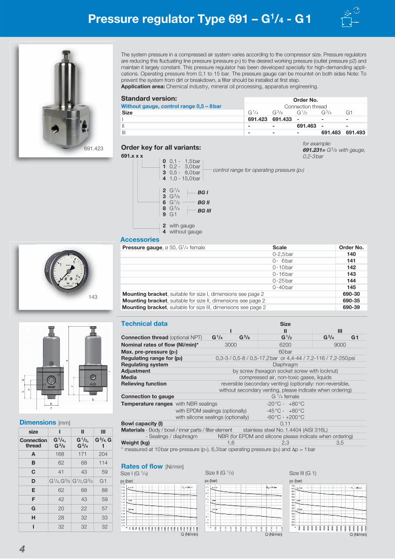
Rates of flow [Nl/min]
Accessories
Standard version:Without gauge, control range 0,5 – 8 bar
Order No.Connection thread
G 1/4 G 3/8 G 1/2 G 3/4 G1691.423 691.433 - - -- - 691.463 - -- - - 691.483 691.493
SizeIIIIII
for example:691.231= G 3/8 with gauge,0,2-3 bar
143
691.423
Size I (G 1/4) Size II (G 1/2) Size III (G 1)
1000
2000
3000
4000
5000
6000
7000
8000
9000
1000
0
1100
0
1200
0
1300
0
1400
0
1500
0
1600
0
1700
0
7.06.56.05.55.04.54.03.53.02.52.01.51.00.50.0
Q (Nl/min) Q (Nl/min) Q (Nl/min)
p2 (bar) p2 (bar) p2 (bar)
Order key for all variants:691.x x x
0 0,1 - 1,5 bar1 0,2 - 3,0 bar3 0,5 - 8,0 bar4 1,0 - 15,0 bar
2 G 1/4 BG I3 G 3/8
6 G 1/2 BG II8 G 3/4 BG III9 G 1
2 with gauge4 without gauge
control range for operating pressure (p2)
Technical data SizeI II III
Connection thread (optional NPT) G 1/4 G 3/8 G 1/2 G 3/4 G 1Nominal rates of flow (Nl/min)* 3000 6200 9000Max. pre-pressure (p1) 60 barRegulating range for (p2) 0,3-3 / 0,5-8 / 0,5-17,2 bar or 4,4-44 / 7,2-116 / 7,2-250 psiRegulating system DiaphragmAdjustment by screw (hexagon socket screw with locknut)Media compressed air, non-toxic gases, liquidsRelieving function reversible (secondary venting) (optionally: non-reversible,
without secondary venting, please indicate when ordering)Connection to gauge G 1/4 femaleTemperature ranges with NBR sealings -20 °C - +80 °C
with EPDM sealings (optionally) -45 °C - +80 °Cwith silicone sealings (optionally) -60 °C - +200 °C
Bowl capacity (l) 0,11Materials - Body / bowl / inner parts / filter element stainless steel No. 1.4404 (AISI 316L)
- Sealings / diaphragm NBR (for EPDM and silicone please indicate when ordering)Weight (kg) 1,6 2,3 3,5* measured at 10 bar pre-pressure (p1), 6,3 bar operating pressure (p2) and Δp = 1 bar
size I II III
Connectionthread
G 1/4 ,G 3/8
G 1/2,G 3/4
G 3/4, G1
A 168 171 204
B 62 68 114
C 41 43 59
D G 1/4,G 3/8 G 1/2,G 3/4 G 1
E 62 68 88
F 42 43 59
G 20 22 57
H 28 32 33
I 32 32 32
Top Related