


Languages
Pages
Legal


ES
PAÑ
OL
Processes
Description
Air Plasma Cuttingand Gouging
Air Plasma Cutter
OM-253 555A 2011−08
Spectrum 375 X-TREMEAnd XT30 Torch
�
File: Plasma CuttersVisit our website at
www.MillerWelds.com
EN
GL
ISH
Miller Electric manufactures a full lineof welders and welding related equipment.For information on other quality Millerproducts, contact your local Miller distributor to receive the latest fullline catalog or individual specification sheets. To locate your nearestdistributor or service agency call 1-800-4-A-Miller, or visit us atwww.MillerWelds.com on the web.
Thank you and congratulations on choosing Miller. Now you can getthe job done and get it done right. We know you don’t have time to doit any other way.
That’s why when Niels Miller first started building arc welders in 1929,he made sure his products offered long-lasting value and superiorquality. Like you, his customers couldn’t afford anything less. Millerproducts had to be more than the best they could be. They had to be thebest you could buy.
Today, the people that build and sell Miller products continue thetradition. They’re just as committed to providing equipment and servicethat meets the high standards of quality and value established in 1929.
This Owner’s Manual is designed to help you get the most out of yourMiller products. Please take time to read the Safety precautions. Theywill help you protect yourself against potential hazards on the worksite.
We’ve made installation and operation quickand easy. With Miller you can count on yearsof reliable service with proper maintenance.And if for some reason the unit needs repair,there’s a Troubleshooting section that willhelp you figure out what the problem is. Theparts list will then help you to decide theexact part you may need to fix the problem.Warranty and service information for yourparticular model are also provided.
Miller is the first weldingequipment manufacturer inthe U.S.A. to be registered tothe ISO 9001 Quality SystemStandard.
Working as hard as you do− every power source fromMiller is backed by the mosthassle-free warranty in thebusiness.
From Miller to You
Mil_Thank 2009−09

TABLE OF CONTENTS
SECTION 1 − SAFETY PRECAUTIONS - READ BEFORE USING 1. . . . . . . . . . . . . . . . . . . . . . . . . . . . . . . . .1-1. Symbol Usage 1. . . . . . . . . . . . . . . . . . . . . . . . . . . . . . . . . . . . . . . . . . . . . . . . . . . . . . . . . . . . . . . . . . . . . . .1-2. Plasma Arc Cutting Hazards 1. . . . . . . . . . . . . . . . . . . . . . . . . . . . . . . . . . . . . . . . . . . . . . . . . . . . . . . . . . .1-3. Additional Symbols For Installation, Operation, And Maintenance 3. . . . . . . . . . . . . . . . . . . . . . . . . . . . .1-4. California Proposition 65 Warnings 4. . . . . . . . . . . . . . . . . . . . . . . . . . . . . . . . . . . . . . . . . . . . . . . . . . . . . .1-5. Principal Safety Standards 4. . . . . . . . . . . . . . . . . . . . . . . . . . . . . . . . . . . . . . . . . . . . . . . . . . . . . . . . . . . . .1-6. EMF Information 4. . . . . . . . . . . . . . . . . . . . . . . . . . . . . . . . . . . . . . . . . . . . . . . . . . . . . . . . . . . . . . . . . . . . .
SECTION 2 − CONSIGNES DE SÉCURITÉ − LIRE AVANT UTILISATION 5. . . . . . . . . . . . . . . . . . . . . . . . . .2-1. Signification des symboles 5. . . . . . . . . . . . . . . . . . . . . . . . . . . . . . . . . . . . . . . . . . . . . . . . . . . . . . . . . . . . .2-2. Dangers liés au coupage à l’arc au plasma 5. . . . . . . . . . . . . . . . . . . . . . . . . . . . . . . . . . . . . . . . . . . . . . .2-3. Dangers supplémentaires en relation avec l’installation, le fonctionnement
et la maintenance 7. . . . . . . . . . . . . . . . . . . . . . . . . . . . . . . . . . . . . . . . . . . . . . . . . . . . . . . . . . . . . . . . . . . .2-4. Proposition californienne 65 Avertissements 9. . . . . . . . . . . . . . . . . . . . . . . . . . . . . . . . . . . . . . . . . . . . . .2-5. Principales normes de sécurité 9. . . . . . . . . . . . . . . . . . . . . . . . . . . . . . . . . . . . . . . . . . . . . . . . . . . . . . . . .2-6. Informations relatives aux CEM 9. . . . . . . . . . . . . . . . . . . . . . . . . . . . . . . . . . . . . . . . . . . . . . . . . . . . . . . . .
SECTION 3 − DEFINITIONS 10. . . . . . . . . . . . . . . . . . . . . . . . . . . . . . . . . . . . . . . . . . . . . . . . . . . . . . . . . . . . . . . . . .3-1. Symbols And Definitions 10. . . . . . . . . . . . . . . . . . . . . . . . . . . . . . . . . . . . . . . . . . . . . . . . . . . . . . . . . . . . . . .
SECTION 4 − SPECIFICATIONS 11. . . . . . . . . . . . . . . . . . . . . . . . . . . . . . . . . . . . . . . . . . . . . . . . . . . . . . . . . . . . . .4-1. Unit Specifications 11. . . . . . . . . . . . . . . . . . . . . . . . . . . . . . . . . . . . . . . . . . . . . . . . . . . . . . . . . . . . . . . . . . . .4-2. Torch Dimensions And Weight 13. . . . . . . . . . . . . . . . . . . . . . . . . . . . . . . . . . . . . . . . . . . . . . . . . . . . . . . . . .4-3. Duty Cycle And Overheating 13. . . . . . . . . . . . . . . . . . . . . . . . . . . . . . . . . . . . . . . . . . . . . . . . . . . . . . . . . . .
SECTION 5 − INSTALLATION 14. . . . . . . . . . . . . . . . . . . . . . . . . . . . . . . . . . . . . . . . . . . . . . . . . . . . . . . . . . . . . . . .5-1. Serial Number And Rating Label Location 14. . . . . . . . . . . . . . . . . . . . . . . . . . . . . . . . . . . . . . . . . . . . . . . .5-2. Selecting A Location 14. . . . . . . . . . . . . . . . . . . . . . . . . . . . . . . . . . . . . . . . . . . . . . . . . . . . . . . . . . . . . . . . . .5-3. Connecting Gas/Air Supply 14. . . . . . . . . . . . . . . . . . . . . . . . . . . . . . . . . . . . . . . . . . . . . . . . . . . . . . . . . . . .5-4. Connecting Work Clamp 15. . . . . . . . . . . . . . . . . . . . . . . . . . . . . . . . . . . . . . . . . . . . . . . . . . . . . . . . . . . . . . .5-5. Electrical Service Guide 15. . . . . . . . . . . . . . . . . . . . . . . . . . . . . . . . . . . . . . . . . . . . . . . . . . . . . . . . . . . . . . .5-6. Extension Cord Data 15. . . . . . . . . . . . . . . . . . . . . . . . . . . . . . . . . . . . . . . . . . . . . . . . . . . . . . . . . . . . . . . . . .5-7. Multi−Voltage Plug (MVP) Connection 16. . . . . . . . . . . . . . . . . . . . . . . . . . . . . . . . . . . . . . . . . . . . . . . . . . .5-8. Connecting 120 Volt Input Power 17. . . . . . . . . . . . . . . . . . . . . . . . . . . . . . . . . . . . . . . . . . . . . . . . . . . . . . . .5-9. Connecting 240 Volt Input Power 18. . . . . . . . . . . . . . . . . . . . . . . . . . . . . . . . . . . . . . . . . . . . . . . . . . . . . . . .
SECTION 6 − OPERATION 19. . . . . . . . . . . . . . . . . . . . . . . . . . . . . . . . . . . . . . . . . . . . . . . . . . . . . . . . . . . . . . . . . . .6-1. Controls 19. . . . . . . . . . . . . . . . . . . . . . . . . . . . . . . . . . . . . . . . . . . . . . . . . . . . . . . . . . . . . . . . . . . . . . . . . . . .6-2. Cutting Speed 20. . . . . . . . . . . . . . . . . . . . . . . . . . . . . . . . . . . . . . . . . . . . . . . . . . . . . . . . . . . . . . . . . . . . . . .6-3. Trigger Safety Lock 21. . . . . . . . . . . . . . . . . . . . . . . . . . . . . . . . . . . . . . . . . . . . . . . . . . . . . . . . . . . . . . . . . . .6-4. Plasma Cutting System Practices 21. . . . . . . . . . . . . . . . . . . . . . . . . . . . . . . . . . . . . . . . . . . . . . . . . . . . . . .6-5. Sequence Of Cutting Operation 22. . . . . . . . . . . . . . . . . . . . . . . . . . . . . . . . . . . . . . . . . . . . . . . . . . . . . . . . .6-6. Sequence Of Piercing Operation 23. . . . . . . . . . . . . . . . . . . . . . . . . . . . . . . . . . . . . . . . . . . . . . . . . . . . . . . .
SECTION 7 − MAINTENANCE & TROUBLESHOOTING 24. . . . . . . . . . . . . . . . . . . . . . . . . . . . . . . . . . . . . . . . .7-1. Routine Maintenance 24. . . . . . . . . . . . . . . . . . . . . . . . . . . . . . . . . . . . . . . . . . . . . . . . . . . . . . . . . . . . . . . . .7-2. Overload Protection 24. . . . . . . . . . . . . . . . . . . . . . . . . . . . . . . . . . . . . . . . . . . . . . . . . . . . . . . . . . . . . . . . . .7-3. Wrapper Removal 25. . . . . . . . . . . . . . . . . . . . . . . . . . . . . . . . . . . . . . . . . . . . . . . . . . . . . . . . . . . . . . . . . . . .7-4. Checking Or Replacing Filter Element 26. . . . . . . . . . . . . . . . . . . . . . . . . . . . . . . . . . . . . . . . . . . . . . . . . . .7-5. Status/Trouble Lights 27. . . . . . . . . . . . . . . . . . . . . . . . . . . . . . . . . . . . . . . . . . . . . . . . . . . . . . . . . . . . . . . . .7-6. Checking Shield Cup Shutdown System 28. . . . . . . . . . . . . . . . . . . . . . . . . . . . . . . . . . . . . . . . . . . . . . . . .7-7. Checking/Replacing Retaining Cup, Tip, And Electrode 29. . . . . . . . . . . . . . . . . . . . . . . . . . . . . . . . . . . . .7-8. Troubleshooting Power Source 30. . . . . . . . . . . . . . . . . . . . . . . . . . . . . . . . . . . . . . . . . . . . . . . . . . . . . . . . .7-9. Troubleshooting Torch 31. . . . . . . . . . . . . . . . . . . . . . . . . . . . . . . . . . . . . . . . . . . . . . . . . . . . . . . . . . . . . . . . .
SECTION 8 − ELECTRICAL DIAGRAM 32. . . . . . . . . . . . . . . . . . . . . . . . . . . . . . . . . . . . . . . . . . . . . . . . . . . . . . . .SECTION 9 − PARTS LIST 34. . . . . . . . . . . . . . . . . . . . . . . . . . . . . . . . . . . . . . . . . . . . . . . . . . . . . . . . . . . . . . . . . . .WARRANTY


OM-253 555 Page 1
SECTION 1 − SAFETY PRECAUTIONS - READ BEFORE USINGpom_2010−03
Protect yourself and others from injury — read and follow these precautions.
1-1. Symbol Usage
DANGER! − Indicates a hazardous situation which, ifnot avoided, will result in death or serious injury. Thepossible hazards are shown in the adjoining symbolsor explained in the text.
Indicates a hazardous situation which, if not avoided,could result in death or serious injury. The possiblehazards are shown in the adjoining symbols or ex-plained in the text.
NOTICE − Indicates statements not related to personal injury.
� Indicates special instructions.
This group of symbols means Warning! Watch Out! ELECTRICSHOCK, MOVING PARTS, and HOT PARTS hazards. Consult sym-bols and related instructions below for necessary actions to avoid thehazards.
1-2. Plasma Arc Cutting Hazards
The symbols shown below are used throughout this manualto call attention to and identify possible hazards. When yousee the symbol, watch out, and follow the related instructionsto avoid the hazard. The safety information given below isonly a summary of the more complete safety informationfound in the Safety Standards listed in Section 1-5. Read andfollow all Safety Standards.
Only qualified persons should install, operate, maintain, andrepair this unit.
During operation, keep everybody, especially children, away.
CUTTING can cause fire or explosion.
Hot metal and sparks blow out from the cutting arc.The flying sparks and hot metal, hot workpiece, andhot equipment can cause fires and burns. Checkand be sure the area is safe before doing any cutting.
� Remove all flammables within 35 ft (10.7 m) of the cutting arc. If thisis not possible, tightly cover them with approved covers.
� Do not cut where flying sparks can strike flammable material.� Protect yourself and others from flying sparks and hot metal.� Be alert that sparks and hot materials from cutting can easily go
through small cracks and openings to adjacent areas.� Watch for fire, and keep a fire extinguisher nearby.� Be aware that cutting on a ceiling, floor, bulkhead, or partition can
cause fire on the hidden side.� Do not cut on closed containers such as tanks or drums.� Connect work cable to the work as close to the cutting area as prac-
tical to prevent cutting current from traveling long, possibly unknownpaths and causing electric shock, sparks, and fire hazards.
� Do not use plasma cutter to thaw frozen pipes.� Never cut containers with potentially flammable materials inside −
they must be emptied and properly cleaned first.
� Do not cut where the atmosphere may contain flammable dust,gas, or liquid vapors (such as gasoline).
� Do not cut pressurized cylinders, pipes, or vessels.� Do not cut containers that have held combustibles.� Wear oil-free protective garments such as leather gloves, heavy
shirt, cuffless trousers, high shoes, and a cap.� Do not locate unit on or over combustible surfaces.� Remove any combustibles, such as a butane lighter or matches,
from your person before doing any cutting.
� After completion of work, inspect area to ensure it is free of sparks,glowing embers, and flames.
� Use only correct fuses or circuit breakers. Do not oversize or by-pass them.
� Follow requirements in OSHA 1910.252 (a) (2) (iv) and NFPA 51Bfor hot work and have a fire watcher and extinguisher nearby.
Touching live electrical parts can cause fatal shocksor severe burns. The torch and work circuit areelectrically live whenever the output is on. The inputpower circuit and machine internal circuits are alsolive when power is on. Plasma arc cutting requires
higher voltages than welding to start and maintain the arc (200 to 400volts dc are common), but may also use torches designed with safetyinterlock systems which turn off the machine when the shield cup isloosened or if tip touches electrode inside the nozzle. Incorrectlyinstalled or improperly grounded equipment is a hazard.
ELECTRIC SHOCK can kill.
� Do not touch live electrical parts.� Wear dry, hole-free insulating gloves and body protection.� Insulate yourself from work and ground using dry insulating mats or
covers big enough to prevent any physical contact with the work orground.
� Do not touch torch parts if in contact with the work or ground.� Turn off power before checking, cleaning, or changing torch parts.� Disconnect input power before installing or servicing this equip-
ment. Lockout/tagout input power according to OSHA CFR1910.147 (see Safety Standards).
� Properly install and ground this equipment according to its Owner’sManual and national, state, and local codes.
� Check and be sure that input power cord ground wire is properlyconnected to ground terminal in disconnect box or that cord plug isconnected to a properly grounded receptacle outlet − always verifythe supply ground.
� When making input connections, attach proper grounding conduc-tor first.
� Keep cords dry, free of oil and grease, and protected from hot metaland sparks.
� Frequently inspect input power cord for damage or bare wiring − re-place cord immediately if damaged − bare wiring can kill.
� Turn off all equipment when not in use.� Inspect and replace any worn or damaged torch cable leads.� Do not wrap torch cable around your body.� Ground the workpiece to a good electrical (earth) ground if required
by codes.� Use only well-maintained equipment. Repair or replace damaged
parts at once.� Wear a safety harness if working above floor level.� Keep all panels and covers securely in place.� Do not bypass or try to defeat the safety interlock systems.� Use only torch(es) specified in Owner’s Manual.� Keep away from torch tip and pilot arc when trigger is pressed.� Clamp work cable with good metal-to-metal contact to workpiece
(not piece that will fall away) or worktable as near the cut aspractical.
� Insulate work clamp when not connected to workpiece to preventcontact with any metal object.

OM-253 555 Page 2
SIGNIFICANT DC VOLTAGE exists ininverter power sources AFTER the re-moval of input power.
� Turn Off unit, disconnect input power, check voltage on input ca-pacitors, and be sure it is near zero (0) volts before touching anyparts. Check capacitors according to instructions in Mainte-nance Section of Owner’s Manual or Technical Manual beforetouching any parts.
ELECTRIC SHOCK can kill.
� On inverter power sources, failed parts can ex-plode or cause other parts to explode whenpower is applied. Always wear a face shieldand long sleeves when servicing inverters.
EXPLODING PARTS can injure.
Sparks and hot metal blow out from the cutting arc.Chipping and grinding cause flying metal.
FLYING SPARKS can injure.
� Wear approved face shield or safety goggles with side shields.� Wear proper body protection to protect skin.� Wear flame-resistant ear plugs or ear muffs to prevent sparks from
entering ears.
Arc rays from the cutting process produce intensevisible and invisible (ultraviolet and infrared) raysthat can burn eyes and skin.
ARC RAYS can burn eyes and skin.
� Wear face protection (helmet or shield) with a proper shade of filterlenses to protect your face and eyes from arc rays and sparks whencutting or watching. ANSI Z49.1 (see Safety Standards) suggests aNo. 9 shade (with No. 8 as minimum) for all cutting currents lessthan 300 amperes. Z49.1 adds that lighter filter shades may be usedwhen the arc is hidden by the workpiece. As this is normally the casewith low current cutting, the shades suggested in Table 1 are pro-vided for the operator’s convenience.
� Wear approved safety glasses with side shields under your helmetor shield.
� Use protective screens or barriers to protect others from flash, glareand sparks; warn others not to watch the arc.
� Wear protective clothing made from durable, flame-resistantmaterial (leather, heavy cotton, or wool) and foot protection.
Table 1. Eye Protection For Plasma Arc Cutting
Current Level In Amperes Minimum Shade NumberBelow 2020 − 4040 − 6060 − 100
#4#5#6#8
Prolonged noise from some cutting applications candamage hearing if levels exceed limits specified byOSHA (see Safety Standards).
NOISE can damage hearing.
� Use approved ear plugs or ear muffs if noise level is high.� Warn others nearby about noise hazard.
FUMES AND GASES can be hazardous.
Cutting produces fumes and gases. Breathingthese fumes and gases can be hazardous toyour health.
� Keep your head out of the fumes. Do not breathe the fumes.� If inside, ventilate the area and/or use local forced ventilation at the
arc to remove cutting fumes and gases.� If ventilation is poor, wear an approved air-supplied respirator.� Read and understand the Material Safety Data Sheets (MSDSs)
and the manufacturer’s instruction for metals to be cut, coatings,and cleaners.
� Work in a confined space only if it is well ventilated, or while wearingan air-supplied respirator. Fumes from cutting and oxygen depletioncan alter air quality causing injury or death. Be sure the breathing airis safe.
� Do not cut in locations near degreasing, cleaning, or spraying oper-ations. The heat and rays of the arc can react with vapors to formhighly toxic and irritating gases.
� Do not cut on coated metals, such as galvanized, lead, or cadmiumplated steel, unless the coating is removed from the cutting area, thearea is well ventilated, and while wearing an air-supplied respirator.The coatings and any metals containing these elements can give offtoxic fumes when cut.
� Do not cut containers with toxic or reactive materials inside orcontainers that have held toxic or reactive materials − they must beemptied and properly cleaned first.
PLASMA ARC can injure.
The heat from the plasma arc can cause seriousburns. The force of the arc adds greatly to the burnhazard. The intensely hot and powerful arc canquickly cut through gloves and tissue.
� Keep away from the torch tip.� Do not grip material near the cutting path.� The pilot arc can cause burns − keep away from torch tip when trig-
ger is pressed.� Wear proper flame-retardant clothing covering all exposed body ar-
eas.� Point torch away from your body and toward work when pressing
the torch trigger − pilot arc comes on immediately.� Turn off power source and disconnect input power before disas-
sembling torch or changing torch parts.� Use only torch(es) specified in the Owner’s Manual.
Gas cylinders contain gas under high pressure. Ifdamaged, a cylinder can explode. Since gas cylin-ders are normally part of metalworking processes,be sure to treat them carefully.
CYLINDERS can explode if damaged.
� Protect compressed gas cylinders from excessive heat, mechani-cal shocks, physical damage, slag, open flame, sparks, and arcs.
� Install and secure cylinders in an upright position by chaining themto a stationary support or equipment cylinder rack to prevent fallingor tipping.
� Keep cylinders away from any cutting or other electrical circuits.� Never allow electrical contact between a plasma arc torch and a
cylinder.� Never cut on a pressurized cylinder − explosion will result.� Use only correct gas cylinders, regulators, hoses, and fittings de-
signed for the specific application; maintain them and associatedparts in good condition.
� Turn face away from valve outlet when opening cylinder valve.� Keep protective cap in place over valve except when cylinder is in
use or connected for use.
� Use the right equipment, correct procedures, and sufficient numberof persons to lift and move cylinders.
� Read and follow instructions on compressed gas cylinders, asso-ciated equipment, and Compressed Gas Association (CGA)publication P-1 listed in Safety Standards.

OM-253 555 Page 3
1-3. Additional Symbols For Installation, Operation, And Maintenance
HOT PARTS can burn.
� Do not touch hot parts bare handed.� Allow cooling period before working on
equipment.� To handle hot parts, use proper tools and/or
wear heavy, insulated welding gloves andclothing to prevent burns.
MOVING PARTS can injure.
� Keep away from moving parts such as fans.� Keep all doors, panels, covers, and guards
closed and securely in place.
� Have only qualified persons remove doors, panels, covers, orguards for maintenance and troubleshooting as necessary.
� Reinstall doors, panels, covers, or guards when maintenance isfinished and before reconnecting input power.
READ INSTRUCTIONS.
� Read and follow all labels and the Owner’sManual carefully before installing, operating, orservicing unit. Read the safety information atthe beginning of the manual and in eachsection.
� Use only genuine replacement parts from the manufacturer.
� Perform maintenance and service according to the Owner’sManuals, industry standards, and national, state, and localcodes.
FLYING METAL or DIRT can injure eyes.
� Wear safety glasses with side shields or wearface shield.
ELECTRIC AND MAGNETIC FIELDS (EMF)can affect Implanted Medical Devices.
� Wearers of Pacemakers and other ImplantedMedical Devices should keep away.
� Implanted Medical Device wearers should consult their doctorand the device manufacturer before going near arc welding, spotwelding, gouging, plasma arc cutting, or induction heatingoperations.
OVERUSE can cause OVERHEATING.
� Allow cooling period; follow rated duty cycle.� Reduce amperage (thickness) or reduce duty
cycle before starting to cut again.
EXPLODING HYDROGEN hazard.
� When cutting aluminum underwater or with thewater touching the underside of the aluminum,free hydrogen gas may collect under the work-piece.
� See your cutting engineer and water table instructions for help.
FALLING EQUIPMENT can injure.
� Use lifting eye to lift unit only, NOT runninggear, gas cylinders, or any other accessories.
� Use equipment of adequate capacity to lift unit.
� If using lift forks to move unit, be sure forks are long enough to ex-tend beyond opposite side of unit.
� Keep equipment (cables and cords) away from moving vehicleswhen working from an aerial location.
� Follow the guidelines in the Applications Manual for the RevisedNIOSH Lifting Equation (Publication No. 94−110) when manuallylifting heavy parts or equipment.
FIRE OR EXPLOSION hazard.
� Do not locate unit on, over, or near combustiblesurfaces.
� Do not install unit near flammables.
� Do not overload building wiring − be sure power supply system isproperly sized, rated, and protected to handle this unit.
STATIC (ESD) can damage PC boards.
� Put on grounded wrist strap BEFORE handlingboards or parts.
� Use proper static-proof bags and boxes tostore, move, or ship PC boards.
H.F. RADIATION can cause interference.
� High frequency (H.F.) can interfere with radionavigation, safety services, computers, andcommunications equipment.
� Have only qualified persons familiar with elec-tronic equipment perform this installation.
� The user is responsible for having a qualified electrician promptlycorrect any interference problem resulting from the installation.
� If notified by the FCC about interference, stop using the equipmentat once.
� Have the installation regularly checked and maintained.
� Keep high-frequency source doors and panels tightly shut, keepspark gaps at correct setting, and use grounding and shielding tominimize the possibility of interference.
ARC CUTTING can cause interference.
� Electromagnetic energy can interfere withsensitive electronic equipment such ascomputers and computer-driven equipmentsuch as robots.
� To reduce possible interference, keep cables as short as possible,close together, and down low, such as on the floor.
� Locate cutting operation 100 meters from any sensitive electronicequipment.
� Be sure this cutting power source is installed and groundedaccording to this manual.
� If interference still occurs, the user must take extra measures suchas moving the machine, using shielded cables, using line filters, orshielding the work area.

OM-253 555 Page 4
1-4. California Proposition 65 Warnings
Welding or cutting equipment produces fumes or gaseswhich contain chemicals known to the State of California tocause birth defects and, in some cases, cancer. (CaliforniaHealth & Safety Code Section 25249.5 et seq.)
Battery posts, terminals and related accessories contain leadand lead compounds, chemicals known to the State ofCalifornia to cause cancer and birth defects or otherreproductive harm. Wash hands after handling.
This product contains chemicals, including lead, known tothe state of California to cause cancer, birth defects, or otherreproductive harm. Wash hands after use.
For Gasoline Engines:
Engine exhaust contains chemicals known to the State ofCalifornia to cause cancer, birth defects, or other reproduc-tive harm.
For Diesel Engines:
Diesel engine exhaust and some of its constituents are knownto the State of California to cause cancer, birth defects, andother reproductive harm.
1-5. Principal Safety Standards
Safety in Welding, Cutting, and Allied Processes, ANSI Standard Z49.1,from Global Engineering Documents (phone: 1-877-413-5184, website:www.global.ihs.com).
Recommended Practices for Plasma Arc Cutting and Gouging, Ameri-can Welding Society Standard AWS C5.2, from Global EngineeringDocuments (phone: 1-877-413-5184, website: www.global.ihs.com).
Safe Practices for the Preparation of Containers and Piping for Weldingand Cutting, American Welding Society Standard AWS F4.1, from Glob-al Engineering Documents (phone: 1-877-413-5184, website:www.global.ihs.com).National Electrical Code, NFPA Standard 70, from National Fire Protec-tion Association, Quincy, MA 02269 (phone: 1-800-344-3555, website:www.nfpa.org and www. sparky.org).Safe Handling of Compressed Gases in Cylinders, CGA Pamphlet P-1,from Compressed Gas Association, 4221 Walney Road, 5th Floor,Chantilly, VA 20151 (phone: 703-788-2700, website:www.cganet.com).Safety in Welding, Cutting, and Allied Processes, CSA StandardW117.2, from Canadian Standards Association, Standards Sales, 5060Spectrum Way, Suite 100, Ontario, Canada L4W 5NS (phone:800-463-6727, website: www.csa-international.org).
Safe Practice For Occupational And Educational Eye And Face Protec-tion, ANSI Standard Z87.1, from American National Standards Institute,25 West 43rd Street, New York, NY 10036 (phone: 212-642-4900, web-site: www.ansi.org).Standard for Fire Prevention During Welding, Cutting, and Other HotWork, NFPA Standard 51B, from National Fire Protection Association,Quincy, MA 02269 (phone: 1-800-344-3555, website: www.nfpa.org.OSHA, Occupational Safety and Health Standards for General Industry,Title 29, Code of Federal Regulations (CFR), Part 1910, Subpart Q, andPart 1926, Subpart J, from U.S. Government Printing Office, Superin-tendent of Documents, P.O. Box 371954, Pittsburgh, PA 15250-7954(phone: 1-866-512-1800) (there are 10 OSHA Regional Offices—phonefor Region 5, Chicago, is 312-353-2220, website: www.osha.gov).Applications Manual for the Revised NIOSH Lifting Equation, The Na-tional Institute for Occupational Safety and Health (NIOSH), 1600Clifton Rd, Atlanta, GA 30333 (phone: 1-800-232-4636, website:www.cdc.gov/NIOSH).
1-6. EMF Information
Electric current flowing through any conductor causes localized electricand magnetic fields (EMF). Welding current creates an EMF field aroundthe welding circuit and welding equipment. EMF fields may interfere withsome medical implants, e.g. pacemakers. Protective measures for per-sons wearing medical implants have to be taken. For example, accessrestrictions for passers−by or individual risk assessment for welders. Allwelders should use the following procedures in order to minimize expos-ure to EMF fields from the welding circuit:
1. Keep cables close together by twisting or taping them, or using acable cover.
2. Do not place your body between welding cables. Arrange cablesto one side and away from the operator.
3. Do not coil or drape cables around your body.
4. Keep head and trunk as far away from the equipment in the weld-ing circuit as possible.
5. Connect work clamp to workpiece as close to the weld aspossible.
6. Do not work next to, sit or lean on the welding power source.
7. Do not weld whilst carrying the welding power source or wirefeeder.
About Implanted Medical Devices:Implanted Medical Device wearers should consult their doctor and thedevice manufacturer before performing or going near arc welding, spotwelding, gouging, plasma arc cutting, or induction heating operations.If cleared by your doctor, then following the above procedures is recom-mended.

OM-253 555 Page 5
SECTION 2 − CONSIGNES DE SÉCURITÉ − LIRE AVANTUTILISATION
pom_2010−03fre
Se protéger et protéger les autres contre le risque de blessure — lire et respecter ces consignes.
2-1. Signification des symboles
DANGER! − Indique une situation dangereuse qui si onl’évite pas peut donner la mort ou des blessures graves.Les dangers possibles sont montrés par les symbolesjoints ou sont expliqués dans le texte.
Indique une situation dangereuse qui si on l’évite paspeut donner la mort ou des blessures graves. Les dan-gers possibles sont montrés par les symboles joints ousont expliqués dans le texte.
NOTE − Indique des déclarations pas en relation avec des blessurespersonnelles.
� Indique des instructions spécifiques.
Ce groupe de symboles veut dire Avertissement! Attention! DANGERDE CHOC ELECTRIQUE, PIECES EN MOUVEMENT, et PIECESCHAUDES. Consulter les symboles et les instructions ci-dessous yafférant pour les actions nécessaires afin d’éviter le danger.
2-2. Dangers liés au coupage à l’arc au plasma
Les symboles présentés ci-après sont utilisés tout au long duprésent manuel pour attirer votre attention et identifier les ris-ques de danger. Lorsque vous voyez un symbole, soyezvigilant et suivez les directives mentionnées afin d’éviter toutdanger. Les consignes de sécurité présentées ci-après nefont que résumer l’information contenue dans les normes desécurité énumérées à la section 1-5. Veuillez lire et respectertoutes ces normes de sécurité.
L’installation, l’utilisation, l’entretien et les réparations ne doi-vent être confiés qu’à des personnes qualifiées.
Au cours de l’utilisation, tenir toute personne à l’écart et plusparticulièrement les enfants.
LE COUPAGE présente un risque defeu ou d’explosion.
Des particules de métal chaud et des étincellespeuvent jaillir de la pièce au moment du coupage.Les étincelles et le métal chaud, la pièce à couperchauffée et l’équipement chaud peuvcnt causer un
feu ou des brûlures. Avant de commencer à travailler, assurez-vousque l’endroit est sécuritaire.
� Déplacez toute matière inflammable se trouvant à l’intérieur d’unpérimètre de 10,7 m (35 pi) de la pièce à couper. Si cela est impos-sible, vous devez les couvrir avec des housses approuvées et bienajustées.
� Ne coupez pas dans un endroit où des étincelles pourraient attein-dre des matières inflammables.
� Protégez−vous, ainsi que toute autre personne travaillant sur leslieux, contre les étincelles et le métal chaud.
� Assurez−vous qu’aucune étincelle ni particule de métal ne peut seglisser dans de petites fissures ou tomber dans d’autres pièces.
� Afin d’éliminer tout risque de feu, soyez vigilant et gardez toujoursun extincteur à la portée de la main.
� Si vous coupez sur un plafond, un plancher ou une cloison, soyezconscient que cela peut entraîner un feu de l’autre côté.
� Ne coupez pas sur un contenant fermé tel qu’un réservoir ou un bi-don.
� Fixez le câble de masse sur la pièce à couper, le plus près possiblede la zone à couper afin de prévenir que le courant de coupage neprenne une trajectoire inconnue ou longue et ne cause ainsi unedécharge électrique, d’étincelles ou un feu.
� Ne pas utiliser le coupeur plasma pour dégeler des conduites ge-lées.
� Ne coupez jamais des contenants qui peuvent contenir des matiè-res inflammables. Vous devez en premier lieu les vider et lesnettoyer convenablement.
� Ne coupez pas quand l’atmosphère peut contenir des poussières,gaz ou vapeurs (comme l’essence) inflammables.
� Ne coupez pas dans un endroit où l’atmosphère risque de contenirde la poussière ou des vapeurs explosives.
� Ne coupez pas de bouteilles, de tuyaux ou de contenants pressuri-sés.
� Ne coupez pas de contenants qui ont déjà reçu des combustibles.
� Portez des vêtements de protection exempts d’huile tels que desgants en cuir, une veste résistante, des pantalons sans revers, desbottes et un casque.
� Ne placez pas le poste sur une surface combustible ou au−dessusde celle−ci.
� Une fois le travail achevé, assurez−vous qu’il ne reste aucune tra-ce d’étincelles incandescentes ni de flammes.
� Utiliser exclusivement des fusibles ou coupe−circuits appropriés.Ne pas augmenter leur puissance; ne pas les ponter.
� Avant le coupage, retirez tout combustible de vos poches, parexemple un briquet au butane ou des allumettes.
Touching live electrical parts can cause fatal shocksor severe burns. The torch and work circuit areelectrically live whenever the output is on. The inputpower circuit and machine internal circuits are alsolive when power is on. Le coupage plasma nécessite
des tensions plus importantes que le soudage pour amorcer etmaintenir l’arc (200 à 400VDC est typique), mais peut être utilisé avecdes torches équipées de systèmes de verrouillage de sécurité quiarrêtent la machine en cas de buse desserrée ou si l’électrode touchela tuyère. Incorrectly installed or improperly grounded equipment is ahazard.
UN CHOC ÉLECTRIQUE peut tuer.
� Ne touchez pas aux pièces électriques sous tension.
� Portez des gants isolants et des vêtements de protection secs etsans trous.
� Isolez−vous de la pièce à couper et du sol en utilisant des houssesou des tapis assez grands afin d’éviter tout contact physique avecla pièce à couper ou le sol.
� Ne touchez pas aux pièces du chalumeau si vous êtes en contactavec la pièce à couper ou le sol.
� Mettez l’appareil hors tension avant d’effectuer la vérification, lenettoyage ou le changement d’une pièce du chalumeau.
� Coupez l’alimentation d’entrée avant d’installer l’appareil ou d’ef-fectuer l’entretien. Verrouillez ou étiquetez la sortie d’alimentationselon la norme OSHA 29 CFR 1910.147 (reportez−vous aux Prin-cipales normes de sécurité).
� Installez le poste correctement et mettez-le à la terre convenable-ment selon les consignes du manuel de l’opérateur et les normesnationales, provinciales et locales.
� Assurez−vous que le fil de terre du cordon d’alimentation est cor-rectement relié à la borne de terre dans la boîte de coupure ou quela fiche du cordon est branchée à une prise correctement mise à laterre − vous devez toujours vérifier la mise à la terre.
OM-253 555 Page 6
� Avant d’effectuer les connexions d’alimentation, vous devez relierle bon fil de terre.
� Les câbles doivent être exempts d’humidité, d’huile et de graisse;protégez−les contre les étincelles et les pièces métalliques chau-des.
� Vérifiez fréquemment le cordon d’alimentation afin de vous assurerqu’il n’est pas altéré ou à nu, remplacez−le immédiatement s’il l’est.Un fil à nu peut entraîner la mort.
� L’équipement doit être hors tension lorsqu’il n’est pas utilisé.
� Vérifiez et remplacez les cosses du câble du chalumeau si ellessont usées ou altérées.
� Le câble du chalumeau ne doit pas s’enrouler autour de votrecorps.
� Si les normes le stipulent, la pièce à couper doit être mise à la terre.
� Utilisez uniquement de l’équipement en bonne condition. Réparezou remplacez immédiatement toute pièce altérée.
� Portez un harnais de sécurité si vous devez travailler au−dessusdu sol.
� Assurez−vous que tous les panneaux et couvercles sont correcte-ment en place.
� N’essayez pas d’aller à l’encontre des systèmes de verrrouillagede sécurité ou de les contourner.
� Utilisez uniquement le ou les chalumeaux recommandés dans lemanuel de l’opérateur.
� N’approchez pas le tube du chalumeau et l’arc pilote lorsque la gâ-chette est enfoncée.
� Le câble de masse doit être pincé correctement sur la pièce à cou-per, métal contre métal (et non de telle sorte qu’il puisse sedétacher), ou sur la table de travail le plus près possible de la lignede coupage.
� Isoler la pince de masse quand pas mis à la pièce pour éviter lecontact avec tout objet métallique.
DÉCHARGES ÉLECTRIQUES poten-tiellement mortelles.
Il reste une TENSION DC NONNÉGLIGEABLE dans les sources desoudage onduleur UNE FOISl’alimentation coupée.
� Mettre l’unité hors tension, mesurer la tension des condensa-teurs d’entrée et s’assurer qu’elle est pratiquement nulle avantde toucher à l’une quelconque des pièces. Mesurer cette tensionconformément aux directives énoncées à la section Entretien dumanuel de l’utilisateur ou du manuel technique avant de toucherà l’une quelconque des pièces.
Risque de blessure en casD’EXPLOSION DES PIÈCES.
� Mise sous tension, toute pièce défectueusedes sources d’alimentation de l’inverseur peutexploser ou faire exploser d’autres pièces.Pour entretenir les inverseurs, toujours porterun masque protecteur et un vêtement à man-ches longues.
Le coupage plasma produit des étincelles et projec-tions de métal à très haute température. Lorsque lapièce refroidit, du laitier peut se former.
LES ÉTINCELLES PROJETÉESpeuvent provoquer des blessures.
� Portez une visière ou des lunettes de sécurité avec des écrans la-téraux approuvées.
� Portez des vêtements de protection adéquats afin de protéger vo-tre peau.
� Ayez recours à des protège−tympans ou à un serre−tête ignifugesafin d’éviter que les étincelles n’entrent dans vos oreilles.
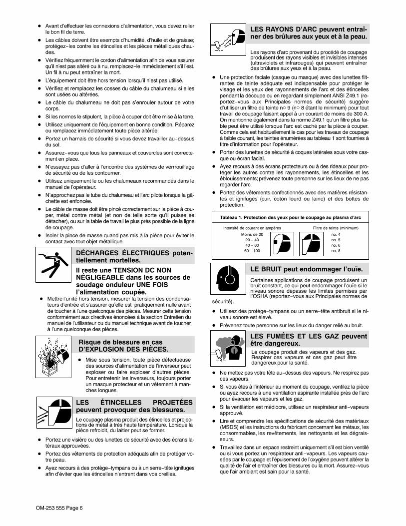
Les rayons d’arc provenant du procédé de coupageproduisent des rayons visibles et invisibles intenses(ultraviolets et infrarouges) qui peuvent entraînerdes brûlures aux yeux et à la peau.
LES RAYONS D’ARC peuvent entraî-ner des brûlures aux yeux et à la peau.
� Une protection faciale (casque ou masque) avec des lunettes filt-rantes de teinte adéquate est indispensable pour protéger levisage et les yeux des rayonnements de l’arc et des étincellespendant la découpe ou en regardant simplement ANSI Z49.1 (re-portez−vous aux Principales normes de sécurité) suggèred’utiliser un filtre de teinte n� 9 (n� 8 étant le minimum) pour touttravail de coupage faisant appel à un courant de moins de 300 A.On mentionne également dans la norme Z49.1 qu’un filtre plus fai-ble peut être utilisé lorsque l’arc est caché par la pièce à couper.Comme cela est habituellement le cas pour les travaux de coupageà faible courant, les teintes énumérées au tableau 1 sont fournies àtitre d’information pour l’opérateur.
� Porter des lunettes de sécurité à coques latérales sous votre cas-que ou écran facial.
� Ayez recours à des écrans protecteurs ou à des rideaux pour pro-téger les autres contre les rayonnements, les étincelles et leséblouissements; prévenez toute personne sur les lieux de ne pasregarder l’arc.
� Portez des vêtements confectionnés avec des matières résistan-tes et ignifuges (cuir, coton lourd ou laine) et des bottes deprotection.
Tableau 1. Protection des yeux pour le coupage au plasma d’arc
Intensité de courant en ampères Filtre de teinte (minimum)
Moins de 20 no. 420 − 40 no. 540 − 60 no. 6
60 − 100 no. 8
Certaines applications de coupage produisent unbruit constant, ce qui peut endommager l’ouïe si leniveau sonore dépasse les limites permises parl’OSHA (reportez−vous aux Principales normes de
sécurité).
LE BRUIT peut endommager l’ouïe.
� Utilisez des protège−tympans ou un serre−tête antibruit si le ni-veau sonore est élevé.
� Prévenez toute personne sur les lieux du danger relié au bruit.
LES FUMÉES ET LES GAZ peuventêtre dangereux.Le coupage produit des vapeurs et des gaz.Respirer ces vapeurs et ces gaz peut êtredangereux pour la santé.
� Ne mettez pas votre tête au−dessus des vapeurs. Ne respirez pasces vapeurs.
� Si vous êtes à l’intérieur au moment du coupage, ventilez la pièceou ayez recours à une ventilation aspirante installée près de l’arcpour évacuer les vapeurs et les gaz.
� Si la ventilation est médiocre, utilisez un respirateur anti−vapeursapprouvé.
� Lire et comprendre les spécifications de sécurité des matériaux(MSDS) et les instructions du fabricant concernant les métaux, lesconsommables, les revêtements, les nettoyants et les dégrais-seurs.
� Travaillez dans un espace restreint uniquement s’il est bien ventiléou si vous portez un respirateur anti−vapeurs. Les vapeurs cau-sées par le coupage et l’épuisement de l’oxygène peuvent altérer laqualité de l’air et entraîner des blessures ou la mort. Assurez−vousque l’air ambiant est sain pour la santé.

OM-253 555 Page 7
� Ne coupez pas dans un endroit près d’opérations de décapage, denettoyage ou de vaporisation. La chaleur et les rayons d’arc peu-vent réagir avec les vapeurs et former des gaz hautement toxiqueset irritants.
� Ne coupez pas des métaux enrobés tels que des métaux galvani-sés, contenant du plomb ou de l’acier plaqué au cadmium, à moinsque l’enrobage ne soit ôté de la surface du métal à couper, que l’en-droit où vous travaillez ne soit bien ventilé, ou que vous ne portiezun respirateur anti−vapeurs. Les enrobages ou tous métaux quicontiennent ces éléments peuvent créer des vapeurs toxiques s’ilssont coupés.
� Ne coupez pas de contenants qui renferment ou ont renfermés desmatières toxiques ou réactives − vous devez en premier lieu les vi-der et les nettoyer convenablement.
L’ARC PLASMA peut provoquer desblessures.
La chaleur dégagée par le plasma d’arc peutentraîner de sérieuses brûlures. La force de l’arc estun facteur qui s’ajoute au danger de brûlures. Lachaleur intense et la puissance de l’arc peuvent
rapidement passer au travers de gants et de tissus.
� N’approchez pas le tube du chalumeau.
� Ne saisissez pas la pièce à couper près de la ligne de coupage.
� L’arc pilote peut causer des brûlures − n’approchez pas le tube duchalumeau lorsque vous avez appuyé sur le gâchette.
� Portez des vêtements de protection adéquats qui recouvrent toutvotre corps.
� Ne pointez pas le chalumeau en direction de votre corps ni de lapièce à couper lorsque vous appuyez sur la gâchette − l’arc pilotes’allume automatiquement.
� Mettez l’alimentation hors tension et débranchez le cordon d’ali-mentation avant de démonter le chalumeau ou de changer unepièce du chalumeau.
� Utilisez uniquement le ou les chalumeaux recommandés dans lemanuel de l’opérateur.
Les bouteilles de gaz contiennent du gaz sous hautepression. Si une bouteille est endommagée, ellepeut exploser. Puisque les bouteilles de gaz fonthabituellement partie d’un processus de travail des
métaux, assurez−vous de les manipuler correctement.
LES BOUTEILLES peuvent explosersi elles sont endommagées.
� Protégez les bouteilles de gaz comprimé contre la chaleur excessi-ve, les chocs mécaniques, des dommages physiques, le laitier, laflamme, les étincelles et l’arc.
� Installez et attachez les bouteilles dans la position verticale à l’aided’une chaîne, sur un support stationnaire ou un châssis porte−bou-teille afin de prévenir qu’elles ne tombent ou ne basculent.
� Les bouteilles ne doivent pas être près de la zone de coupage ni detout autre circuit électrique.
� Un contact électrique ne doit jamais se produire entre un chalu-meau de plasma d’arc et une bouteille.
� Ne coupez jamais sur une bouteille pressurisée − une explosion enrésulterait.
� Utilisez uniquement des bouteilles de gaz, des détendeurs, desboyaux et des raccords conçus pour l’application déterminée. Gar-dez−les, ainsi que toute autre pièce associée, en bonne condition.
� Détournez votre visage du détendeur−régulateur lorsque vous ou-vrez la soupape de la bouteille.
� Le couvercle du détendeur doit toujours être en place, sauf lorsquevous utilisez la bouteille ou qu’elle est reliée pour usage ultérieur.
� Utiliser les équipements corrects, les bonnes procédures et suffi-samment de personnes pour soulever et déplacer les bouteilles.
� Lire et suivre les instructions sur les bouteilles de gaz comprimé,l’équipement connexe et le dépliant P-1 de la CGA (CompressedGas Association) mentionné dans les principales normes de sécu-rité.
2-3. Dangers supplémentaires en relation avec l’installation, le fonctionnementet la maintenance
LES PIÈCES CHAUDES peuventprovoquer des brûlures.
� Ne pas toucher des parties chaudes à mainsnues.
� Prévoir une période de refroidissement avantd’utiliser l’équipement.
� Ne pas toucher aux pièces chaudes, utiliser les outils recom-mandés et porter des gants de soudage et des vêtements épaispour éviter les brûlures.
Les PIÈCES MOBILES peuventprovoquer des blessures.
� S’abstenir de toucher des organes mobiles telsque des ventilateurs.
� Maintenir fermés et verrouillés les portes, pan-neaux, recouvrements et dispositifs de protec-tion.
� Lorsque cela est nécessaire pour des travaux d’entretien et dedépannage, faire retirer les portes, panneaux, recouvrementsou dispositifs de protection uniquement par du personnel qua-lifié.
� Remettre les portes, panneaux, recouvrements ou dispositifs deprotection quand l’entretien est terminé et avant de rebrancherl’alimentation électrique.
LIRE LES INSTRUCTIONS.
� Lire et appliquer les instructions sur lesétiquettes et le Mode d’emploi avant l’instal-lation, l’utilisation ou l’entretien de l’appareil.Lire les informations de sécurité au début dumanuel et dans chaque section.
� N’utiliser que les pièces de rechange recommandées par leconstructeur.
� Effectuer l’entretien en respectant les manuels d’utilisation, lesnormes industrielles et les codes nationaux, d’état et locaux.
DES PIECES DE METAL ou DES SA-LETES peuvent provoquer des bles-sures dans les yeux.
� Porter des lunettes de sécurité avec écrans latéraux ou un écranfacial.

OM-253 555 Page 8
Les CHAMPS ÉLECTROMAGNÉTIQUES (CEM)peuvent affecter les implants médicaux.
� Les porteurs de stimulateurs cardiaqueset autres implants médicaux doivent resterà distance.
� Les porteurs d’implants médicaux doivent consulterleur médecin et le fabricant du dispositif avant de s’approcherde la zone où se déroule du soudage à l’arc, du soudagepar points, du gougeage, de la découpe plasmaou une opération de chauffage par induction.
L’EMPLOI EXCESSIF peutSURCHAUFFER L’ÉQUIPEMENT.
� Prévoir une période de refroidissement; re-specter le cycle opératoire nominal.
� Réduire l’ampérage (épaisseur) avant de con-tinuer à couper ou réduire le facteur de marche.
Danger D’EXPLOSIOND’HYDROGÈNE.
� Lors du coupage d’aluminium partiellement outotalement immergé dans l’eau, de l’hydrogènelibre peut s’accumuler sous la pièce.
� Consultez votre ingénieur de coupage et les instructions de latable de coupage.
LA CHUTE DE L’ÉQUIPEMENT peutprovoquer des blessures.
� Utiliser l’anneau de levage uniquement poursoulever l’appareil, NON PAS les chariot, lesbouteilles de gaz ou tout autre accessoire.
� Utiliser un engin d’une capacité appropriéepour soulever l’appareil.
� En utilisant des fourches de levage pour déplacer l’unité, s’assu-rer que les fourches sont suffisamment longues pour dépasserdu côté opposé de l’appareil.
� Tenir l’équipement (câbles et cordons) à distance des véhiculesmobiles lors de toute opération en hauteur.
� Suivre les consignes du Manuel des applications pour l’équationde levage NIOSH révisée (Publication Nº94–110) lors du levagemanuelle de pièces ou équipements lourds.
Risque D’INCENDIE OUD’EXPLOSION.
� Ne pas placer l’appareil sur, au-dessus ou àproximité de surfaces infllammables.
� Ne pas installer l’appareil à proximité de pro-duits inflammables
� Ne pas surcharger l’installation électrique − s’assurer que l’alimen-tation est correctement dimensionné et protégé avant de mettrel’appareil en service.
LES CHARGES ÉLECTROSTATI-QUES peuvent endommager les cir-cuits imprimés.
� Etablir la connexion avec la barrette de terreavant de manipuler des cartes ou des pièces.
� Utiliser des pochettes et des boîtes antistatiques pour stocker,déplacer ou expédier des cartes PC.
LE RAYONNEMENT HAUTE FRÉ-QUENCE (H.F.) risque de provoquerdes interférences.
� Le Rayonnement haute frequence (H.F.) peutprovoquer des interférences avec les équipe-ments de radio−navigation et de communica-tion, les services de sécurité et les ordinateurs.
� Demander seulement à des personnes qualifiées familiariséesavec des équipements électroniques de faire fonctionner l’installa-tion.
� L’utilisateur est tenu de faire corriger rapidement par un électricienqualifié les interférences résultant de l’installation.
� Si le FCC signale des interférences, arrêter immédiatement l’appa-reil.
� Effectuer régulièrement le contrôle et l’entretien de l’installation.
� Maintenir soigneusement fermés les portes et les panneaux dessources de haute fréquence, maintenir les éclateurs à une distan-ce correcte et utiliser une terre et et un blindage pour réduire lesinterférences éventuelles.
LE COUPAGE Ã L’ARC peut causerdes interférence.
� L’énergie électromagnétique peut gêner lefonctionnement d’appareils électroniquescomme des ordinateurs et des robots.
� Pour réduire la possibilité d’interférence, maintenir les câbles aussicourts que possible, les grouper, et les poser aussi bas que possi-ble (ex. par terre).
� Veiller à couper à une distance de 100 mètres de tout équipementélectronique sensible.
� S’assurer que la source de coupage est correctement branchée etmise à la terre.
� Si l’interférence persiste, l’utilisateur doit prendre des mesuressupplémentaires comme écarter la machine, utiliser des câblesblindés de des filtres, ou boucler la zone de travail.

OM-253 555 Page 9
2-4. Proposition californienne 65 Avertissements
Les équipements de soudage et de coupage produisent desfumées et des gaz qui contiennent des produits chimiquesdont l’État de Californie reconnaît qu’ils provoquent des mal-formations congénitales et, dans certains cas, des cancers.(Code de santé et de sécurité de Californie, chapitre 25249.5et suivants)
Ce produit contient des produits chimiques, compris duplomb, dont l’État de Californie reconnaît qu’ils provoquentdes cancers et des malformations congénitales ou autresproblèmes de procréation. Se laver les mains aprèsmanipulation.
Ce produit contient des éléments chimiques, dont le plomb,reconnus par l’État de Californie pour leur caractère
cancérogène ainsi que provoquant des malformationscongénitales ou autres problèmes de procréation. Se laver lesmains après toute manipulation.
Pour les moteurs à essence :
Les gaz d’échappement des moteurs contiennent des pro-duits chimiques dont l’État de Californie reconnaît qu’ilsprovoquent des cancers et des malformations congénitalesou autres problèmes de procréation.
Pour les moteurs diesel :
Les gaz d’échappement des moteurs diesel et certains deleurs composants sont reconnus par l’État de Californie com-me provoquant des cancers et des malformationscongénitales ou autres problèmes de procréation.
2-5. Principales normes de sécuritéSafety in Welding, Cutting, and Allied Processes, ANSI Standard Z49.1,de Global Engineering Documents (téléphone : 1-877-413-5184, site In-ternet : www.global.ihs.com).
Recommended Practices for Plasma Arc Cutting and Gouging, Ameri-can Welding Society Standard AWS C5.2, de Global EngineeringDocuments (téléphone : 1-877-413-5184, site internet :www.global.ihs.com).
Safe Practices for the Preparation of Containers and Piping for Weldingand Cutting, American Welding Society Standard AWS F4.1, de GlobalEngineering Documents (téléphone: 1-877-413-5184, site internet :www.global.ihs.com).National Electrical Code, NFPA Standard 70, de National Fire ProtectionAssociation, Quincy, MA 02269 (téléphone : 1-800-344-3555, site Inter-net : www.nfpa.org et www.sparky.org).
Safe Handling of Compressed Gases in Cylinders, CGA Pamphlet P-1,de Compressed Gas Association, 4221 Walney Road, 5th Floor, Chan-tilly, VA 20151 (téléphone : 703-788-2700, site Internet :www.cganet.com).
Safety in Welding, Cutting, and Allied Processes, CSA StandardW117.2, de Canadian Standards Association, Standards Sales, 5060Spectrum Way, Suite 100, Ontario, Canada L4W 5NS (téléphone :800-463-6727, site internet : www.csa-international.org).
Safe Practice For Occupational And Educational Eye And Face Protec-tion, ANSI Standard Z87.1, de American National Standards Institute,25 West 43rd Street, New York, NY 10036 (téléphone : 212-642-4900,site Internet : www.ansi.org).
Standard for Fire Prevention During Welding, Cutting, and Other HotWork, NFPA Standard 51B, de National Fire Protection Association,Quincy, MA 02269 (téléphone : 1-800-344-3555, site Internet :www.nfpa.org).
OSHA, Occupational Safety and Health Standards for General Industry,Title 29, Code of Federal Regulations (CFR), Part 1910, Subpart Q, andPart 1926, Subpart J, de U.S. Government Printing Office, Superinten-dent of Documents, P.O. Box 371954, Pittsburgh, PA 15250-7954(téléphone : 1-866-512-1800) (il y a 10 bureaux régionaux −le téléphonede la région 5, Chicago, est 312-353-2220, site Internet :www.osha.gov).
Applications Manual for the Revised NIOSH Lifting Equation, The Na-tional Institute for Occupational Safety and Health (NIOSH), 1600Clifton Rd, Atlanta, GA 30333(téléphone: 1-800-232-4636, site internet : www.cdc.gov/NIOSH).
2-6. Informations relatives aux CEM
Le courant électrique qui traverse tout conducteur génère des champsélectromagnétiques (CEM) à certains endroits. Le courant de soudagecrée un CEM autour du circuit et du matériel de soudage. Les CEMpeuvent créer des interférences avec certains implants médicauxcomme des stimulateurs cardiaques. Des mesures de protection pourles porteurs d’implants médicaux doivent être prises: par exemple, desrestrictions d’accès pour les passants ou une évaluation individuelledes risques pour les soudeurs. Tous les soudeurs doivent appliquer lesprocédures suivantes pour minimiser l’exposition aux CEM provenantdu circuit de soudage:
1. Rassembler les câbles en les torsadant ou en les attachant avecdu ruban adhésif ou avec une housse.
2. Ne pas se tenir au milieu des câbles de soudage. Disposer lescâbles d’un côté et à distance de l’opérateur.
3. Ne pas courber et ne pas entourer les câbles autour de votrecorps.
4. Maintenir la tête et le torse aussi loin que possible du matériel ducircuit de soudage.
5. Connecter la pince sur la pièce aussi près que possible de lasoudure.
6. Ne pas travailler à proximité d’une source de soudage, nis’asseoir ou se pencher dessus.
7. Ne pas souder tout en portant la source de soudage ou ledévidoir.
En ce qui concerne les implants médicaux :Les porteurs d’implants doivent d’abord consulter leur médecin avant des’approcher des opérations de soudage à l’arc, de soudage par points,de gougeage, du coupage plasma ou de chauffage par induction. Si lemédecin approuve, il est recommandé de suivre les procédures précé-dentes.

� A complete Parts List is available at www.MillerWelds.com
OM-253 555 Page 10
SECTION 3 − DEFINITIONS
3-1. Symbols And Definitions
A AmperesPlasma Arc Cutting
(PAC)Adjust Air/Gas
PressureLow Air Pressure
Light
V Volts IncreaseNo − Do Not Do
This Temperature
Protective Earth(Ground) Single Phase Constant Current Voltage Input
On Off Percent Direct Current
U0Rated No Load
Voltage (Average) U1Primary Voltage U2
Conventional LoadVoltage Line Connection
I1maxRated MaximumSupply Current I2
Rated Welding OrCutting Current X Duty Cycle
Single PhaseStatic Frequency
Converter-Transformer-
Rectifier
IP Degree OfProtection Loose Shield Cup Input Hz Hertz
I1effMaximum Effective
Supply Current pf power factor SSuitable for Some
HazardousLocations
S1Power Rating,
Product Of VoltageAnd Current (kVA)

� A complete Parts List is available at www.MillerWelds.com
OM-253 555 Page 11
SECTION 4 − SPECIFICATIONS
4-1. Unit Specifications
Power Supply
Input
Rated AC Phase and line frequency (Hz) 1 − Phase 50 / 60 Hz −−Rated Input Voltage (U1) and rated Input Current (I1)and I1 eff at rated output. I1 eff used to determine powercord rating
Volts AC RMS − (U1) Amps RMS − (I1) I1 eff
120 VAC, 1−Phase (20 A) 25.6 11.4
120 VAC, 1−Phase (15 A) 18.1 10.7
240 VAC, 1−Phase 13.6 8.1
Power Factor/kVA/kW at Rated Output Volts AC RMS − (U1) Power Factor kVA/kW
120 VAC, 1−Phase (20 A) 0.982 3.08 / 3.03
120 VAC, 1−Phase (15 A) 0.983 2.19 / 2.15
240 VAC, 1−Phase 0.995 3.31 / 3.29
Peak kW at Arc Stretch kW 7.0 −−
Output
Rated Open Circuit Voltage (U0) Type 400 Volts DC/Electrode Negative −− −−
Output Characteristic Constant Current −− −−
Rated Output Current and Voltage (I2, U2) at rated InputVoltage (U1)
Volts AC RMS - (U1) Amps DC - (I2) Volts DC - (U2)
120 VAC, 1−Phase (20A) 27 A 91 V
120 VAC, 1−Phase (15 A) 20 A 88 V
240 VAC, 1−Phase 30 A 92 V
Output Current Range 15 − 30 A −− −−Duty Cycle at 104°F (40�C) and Rated Conditions(U1, I1, U2, I2) based on a 10 minute period
Volts AC RMS - (U1) Amps DC − (I2) Duty Cycle %
120 VAC, 1−Phase (20A) 27 A 20%
120 VAC, 1−Phase (15 A) 20 A 35%
240 VAC, 1−Phase 30 A 35%
240 VAC, 1−Phase 22 A 100%

� A complete Parts List is available at www.MillerWelds.com
OM-253 555 Page 12
General
Operating Temperature 5° to 104° F (−15° to 40° C) −− −−
IP Code − Degree of protection provided by enclosure IP23CS −− −−
IP − International Protection −− −−2 − No ingress of foreign objects
≥12.5 mm (0.5 in.)−− −−
3 − No harmful ingress sprayingwater −− −−
C − AC line circuits protectedagainst ingress of tool . 2.5 mm
dia x 100 mm long (0.1 in. x 4 in.)−− −−
S − Fan stationary during watertest −− −−
Toppling or tilting Up to 15° incline −− −−
Torch − The XT30 torch is intended for handheld use only. The torch conforms to IEC 60974-7 when used with the Spectrum 375X-TREME. Do not use this torch in combination with any other machines.
Gas Type Air or Nitrogen −− −−
Gas QualityClean, moisture−free,
oil−free −− −−
Gas Inlet Flow and Pressure 5.0 SCFM (142 L/min)90 PSI (621 kPa)
Min120 PSI (827 kPa)
Max
Gas Filtering Particulates to 5 microns −− −−
Mild Steel capacities (see Section 6-2 for cutting speeds vs material type and thickness)
Cooling Method Air −− −−Duty Cycle of Torch 100% at 30 Amps −− −−Rating of Electrical Controls (Trigger) 30 VDC at .1 Amps − − − −
Rating of Electrical Controls (Cup) 30 VDC at 1 Amp − − − −
Approved Systems Spectrum 375 X-TREME w/XT30torch
Trigger Protection Safety trigger guard
Safety Devices Safety interlock devices shutdown power source
Rated Capacity (edge start) 3/8 in. at 18 ipm (457 mm/min)* −− −−
Sever Cut Capacity (edge start) 5/8 in. −− −−
Pierce Capacity 3/16 in. −− −−*Travel speeds are approximately 80% of maximum.
Dimensions 13-1/8 in. (333 mm) L5-1/2 in. (140 mm) W
9 in. (229 mm) H
− − − −
Weight 18 lb (8.2 kg) including torch − − − −
Requirements for the torch connection� Use only compressed air which is free from dirt, oil, and water.� Ensure that the connections are properly assigned and tighened.� For torch replacement, see Miller torch manual Part No. OM-1593� Ensure correct air pressure (flow pressure) and airflow (volume) are set. Insufficient airflow can lead to the torch overheating.

� A complete Parts List is available at www.MillerWelds.com
OM-253 555 Page 13
4-2. Torch Dimensions And Weight
Ref. 253 554-A
2.2 lb (1.0 kg)
1-3/16 in.(30 mm)
8-3/4 in.(222 mm)
1-1/2 in.(38 mm)
4-3. Duty Cycle And Overheating
Duty Cycle is percentage of 10minutes that unit can cut at ratedload without overheating.
If unit overheats, thermostat(s)opens, output stops, Temperaturetrouble light goes On, and coolingfan runs. Wait fifteen minutes forunit to cool or temperature light togo off. Reduce amperage or dutycycle before cutting or gouging.
NOTICE − Exceeding duty cyclecan damage unit and void warranty.
Overheating
sduty1 5/95 / Ref. 804 503-A
3-1/2 Minutes Cutting 6-1/2 Minutes Resting
35% duty cycle
0
15
Minutes
A
ORReduce Duty Cycle
2 Minutes Cutting 8 Minutes Resting
20% duty cycle

� A complete Parts List is available at www.MillerWelds.com
OM-253 555 Page 14
SECTION 5 − INSTALLATION5-1. Serial Number And Rating Label LocationThe serial number and rating information for this product is located on the bottom. Use rating label to determine input power requirements and/or ratedoutput. For future reference, write serial number in space provided on back cover of this manual.
5-2. Selecting A Location
loc_2 3/96 - Ref. ST-151 556 / Ref. 804 503-A
1 Line Disconnect Device
Locate unit near correct inputpower supply.
Locate unit at least 18 in. (460 mm)away from a wall or otherobstruction to allow adequateclearance for cooling air flow.
! Special installation may berequired where gasoline orvolatile liquids are present −see NEC Article 511 or CECSection 20.
Location
1
18 in.(460 mm)
18 in.(460 mm)
! Do not move or operateunit where it could tip.
5-3. Connecting Gas/Air Supply
Ref. 251 808-A
� Use only clean, dry air with 90to 120 psi (621 to 827 kPa)pressure.
1 Gas/Air Inlet Opening
2 Hose
3 Teflon Tape
Obtain hose with 1/4 NPT right-hand thread fitting. Wrap threadswith teflon tape (optional) or applypipe sealant, and install fitting inopening. Route hose to gas/airsupply.
Tools Needed:
9/16 in.
3From Gas/Air
Supply
1
2

� A complete Parts List is available at www.MillerWelds.com
OM-253 555 Page 15
5-4. Connecting Work Clamp
Ref. 803 640-A
1 Work Clamp
2 Workpiece
Connect work clamp to a clean,paint-free location on workpiece, asclose to cutting area as possible.
1
2
5-5. Electrical Service Guide
Failure to follow these electrical service guide recommendations could create an electric shock or fire hazard. These recommenda-tions are for a dedicated branch circuit sized for the rated output and duty cycle of the welding power source.
NOTICE − Actual input voltage should not be 10% less than minimum and/or 10% more than maximum input voltages listed in table. If actual inputvoltage is outside this range, output may not be be available.
50/60 Hz Single Phase
Input Voltage (V) 120 240
Input Amperes (A) At Rated Output
A 15 or 20ampere individual
branch circuitprotected by
time-delay fusesor circuit breaker
is required.See Section 4-1
14
Max Recommended Standard Fuse Rating In Amperes 1
Time-Delay Fuses 2 15
Normal Operating Fuses 3 25
Min Input Conductor Size In AWG 4 14
Max Recommended Input Conductor Length In Feet (Meters)96
(29)
Min Grounding Conductor Size In AWG 4 14
Elec Serv 2011−04
Reference: 2011 National Electrical Code (NEC) (including article 630)1 If a circuit breaker is used in place of a fuse, choose a circuit breaker with time-current curves comparable to the recommended fuse.
2 “Time-Delay” fuses are UL class “RK5” . See UL 248.3 “Normal Operating” (general purpose - no intentional delay) fuses are UL class “K5” (up to and including 60 amps), and UL class “H” ( 65 amps and
above).4 Conductor data in this section specifies conductor size (excluding flexible cord or cable) between the panelboard and the equipment per NEC Table
310.15(B)(16). If a flexible cord or cable is used, minimum conductor size may increase. See NEC Table 400.5(A) for flexible cord and cablerequirements.
5-6. Extension Cord Data
� When calculating max. cord length, remember to include conductor length from line disconnect device to input power receptacle.
Single Phase AC
Input Voltage
Conductor Size − AWG (mm2)*
6 (13.3) 8 (8.4) 10 (5.3) 12 (3.3) 14 (2.1)
Maximum Allowable Cord Length in ft (m)
120 175 (53) 110 (33) 70 (21) 44 (13) 28 (9)
240 700 (213) 440 (134) 277 (84) 175 (53) 110 (33)
*Conductor size is based on maximum 3% voltage drop

� A complete Parts List is available at www.MillerWelds.com
OM-253 555 Page 16
5-7. Multi−Voltage Plug (MVP) Connection
Selecting Plug
1 Power Cord Connector FromWelding Power Source
Select plug for power supply receptacleavailable at site. Not all plugs shown areprovided as standard with unit.
2 Plug − NEMA Type 5−15P
3 Receptacle − NEMA Type 5−15R(Customer Supplied)
4 Plug − NEMA Type 5−20P (Optional)
5 Receptacle − NEMA Type 5−20R(Customer Supplied)
6 Plug − NEMA Type 6−50P
7 Receptacle − NEMA Type 6−50R(Customer Supplied)
! Follow electrical service guide for240 VAC in Section 5-5. Do not useplug rating to size branch circuitprotection.
Connecting Plug To Power Cord
Align arrow on plug with arrow on powercord connector. Push together.
Tighten threaded collar. As threaded collaris tightened, push plug onto adapter untilcollar is completely tight.
Connect plug to receptacle.
MVP Plug1 2010−10 / Ref. 803 812-C
! Do not cut off power cord connec-tor and rewire. The power cordconnector and plugs will workwith standard NEMA receptacles.Modifying power cord, connector,and plugs will void product war-ranty.
3
2
7
4
5
6
1
Selecting Plug
Connecting Plug To Power Cord
� A complete Parts List is available at www.MillerWelds.com
OM-253 555 Page 17
Input6 2011−03 Ref. 253 558-A
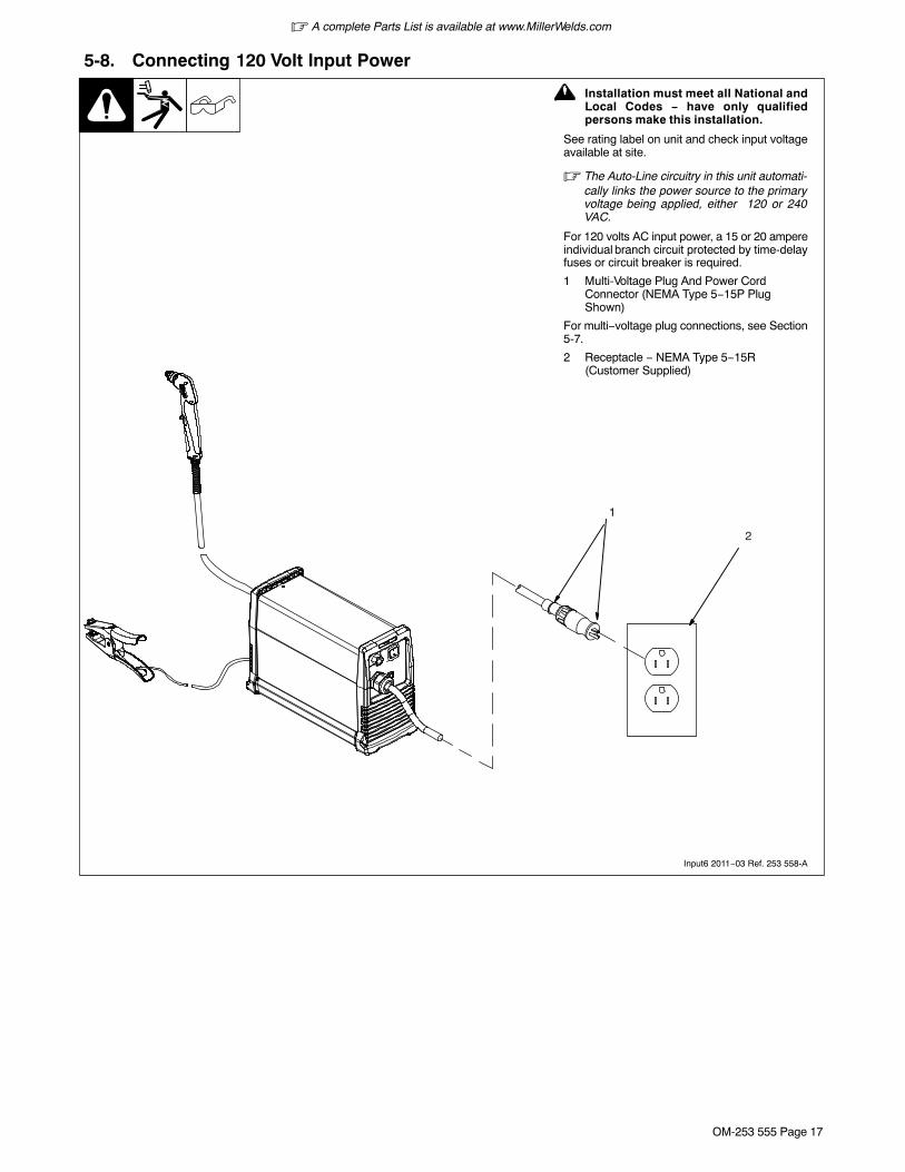
5-8. Connecting 120 Volt Input Power
1
! Installation must meet all National andLocal Codes − have only qualifiedpersons make this installation.
See rating label on unit and check input voltageavailable at site.
� The Auto-Line circuitry in this unit automati-cally links the power source to the primaryvoltage being applied, either 120 or 240VAC.
For 120 volts AC input power, a 15 or 20 ampereindividual branch circuit protected by time-delayfuses or circuit breaker is required.
1 Multi-Voltage Plug And Power CordConnector (NEMA Type 5−15P PlugShown)
For multi−voltage plug connections, see Section5-7.
2 Receptacle − NEMA Type 5−15R(Customer Supplied)
2
� A complete Parts List is available at www.MillerWelds.com
OM-253 555 Page 18
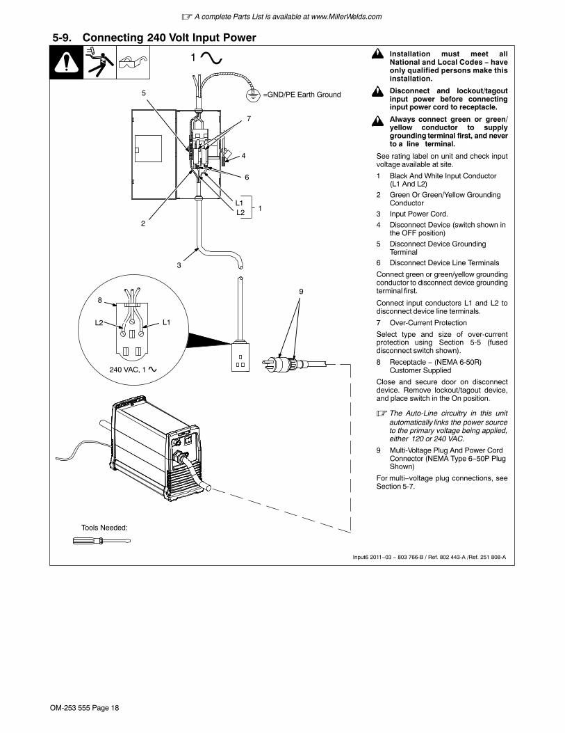
5-9. Connecting 240 Volt Input Power
Input6 2011−03 − 803 766-B / Ref. 802 443-A /Ref. 251 808-A
! Installation must meet allNational and Local Codes − haveonly qualified persons make thisinstallation.
! Disconnect and lockout/tagoutinput power before connectinginput power cord to receptacle.
! Always connect green or green/yellow conductor to supplygrounding terminal first, and neverto a line terminal.
See rating label on unit and check inputvoltage available at site.
1 Black And White Input Conductor(L1 And L2)
2 Green Or Green/Yellow GroundingConductor
3 Input Power Cord.
4 Disconnect Device (switch shown inthe OFF position)
5 Disconnect Device GroundingTerminal
6 Disconnect Device Line Terminals
Connect green or green/yellow groundingconductor to disconnect device groundingterminal first.
Connect input conductors L1 and L2 todisconnect device line terminals.
7 Over-Current Protection
Select type and size of over-currentprotection using Section 5-5 (fuseddisconnect switch shown).
8 Receptacle − (NEMA 6-50R)Customer Supplied
Close and secure door on disconnectdevice. Remove lockout/tagout device,and place switch in the On position.
� The Auto-Line circuitry in this unitautomatically links the power sourceto the primary voltage being applied,either 120 or 240 VAC.
9 Multi-Voltage Plug And Power CordConnector (NEMA Type 6−50P PlugShown)
For multi−voltage plug connections, seeSection 5-7.
4
3
L1L2
1
=GND/PE Earth Ground
2
1
5
6
7
Tools Needed:
L1L2
240 VAC, 1
89

� A complete Parts List is available at www.MillerWelds.com
OM-253 555 Page 19
SECTION 6 − OPERATION6-1. Controls
1 Output Control
Use control to set cutting output.
If 22-27 amperes of cutting output is used
with 120 VAC input power, and the overloadprotection on the input power circuit fre-quently opens, either reduce the cutting out-put and/or the cut time or find more adequate
power (see Section 4-1).
2 Power Light
3 Trouble Lights (See Section 7-5)
253 014-A
3
12
� A complete Parts List is available at www.MillerWelds.com
OM-253 555 Page 20
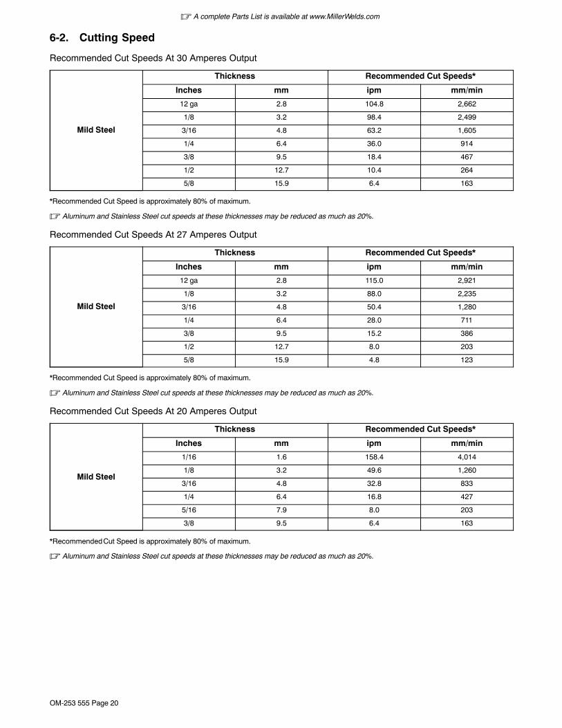
6-2. Cutting Speed
Recommended Cut Speeds At 30 Amperes Output
Mild Steel
Thickness Recommended Cut Speeds*
Inches mm ipm mm/min
12 ga 2.8 104.8 2,662
1/8 3.2 98.4 2,499
3/16 4.8 63.2 1,605
1/4 6.4 36.0 914
3/8 9.5 18.4 467
1/2 12.7 10.4 264
5/8 15.9 6.4 163
*Recommended Cut Speed is approximately 80% of maximum.
� Aluminum and Stainless Steel cut speeds at these thicknesses may be reduced as much as 20%.
Recommended Cut Speeds At 27 Amperes Output
Mild Steel
Thickness Recommended Cut Speeds*
Inches mm ipm mm/min
12 ga 2.8 115.0 2,921
1/8 3.2 88.0 2,235
3/16 4.8 50.4 1,280
1/4 6.4 28.0 711
3/8 9.5 15.2 386
1/2 12.7 8.0 203
5/8 15.9 4.8 123
*Recommended Cut Speed is approximately 80% of maximum.
� Aluminum and Stainless Steel cut speeds at these thicknesses may be reduced as much as 20%.
Recommended Cut Speeds At 20 Amperes Output
Mild Steel
Thickness Recommended Cut Speeds*
Inches mm ipm mm/min
1/16 1.6 158.4 4,014
1/8 3.2 49.6 1,260
3/16 4.8 32.8 833
1/4 6.4 16.8 427
5/16 7.9 8.0 203
3/8 9.5 6.4 163
*Recommended Cut Speed is approximately 80% of maximum.
� Aluminum and Stainless Steel cut speeds at these thicknesses may be reduced as much as 20%.

� A complete Parts List is available at www.MillerWelds.com
OM-253 555 Page 21
6-3. Trigger Safety Lock
Trigger Locked Trigger Unlocked
1 Trigger
Ref. 253554-A
1
Ref. 254 087-A
6-4. Plasma Cutting System Practices
Pulling rather than pushing the torchmakes cutting easier. Use a proper guide
or template for accurate cutting operations.
! The pilot arc starts immediatelywhen trigger is pressed.
Maintain approximately a 90° angle to theworkpiece surface for proper cutting results.
Always connect work clamp to a clean,paint-free location on workpiece, as close to
cutting area as possible.
90°
DO NOT start pilot arc without cutting orgouging as this shortens the service life
of the nozzle and electrode.
Sparks should pass through the workpieceand out the bottom when cutting.
If sparks flare back from surface, thisusually is an indication that either travel
speed is too fast or amperage is set too low.
When doing extended (non-shielded)cutting, maintain approximately 1/16 in.standoff between electrode and surface.
1/16 in.(1.6 mm)
DO NOT put pressure on shield whendrag cutting; instead, slide shield along
the surface for proper cutting results.
Wt
� A complete Parts List is available at www.MillerWelds.com
OM-253 555 Page 22
out bottom of cut.
Ref. 254 087-A
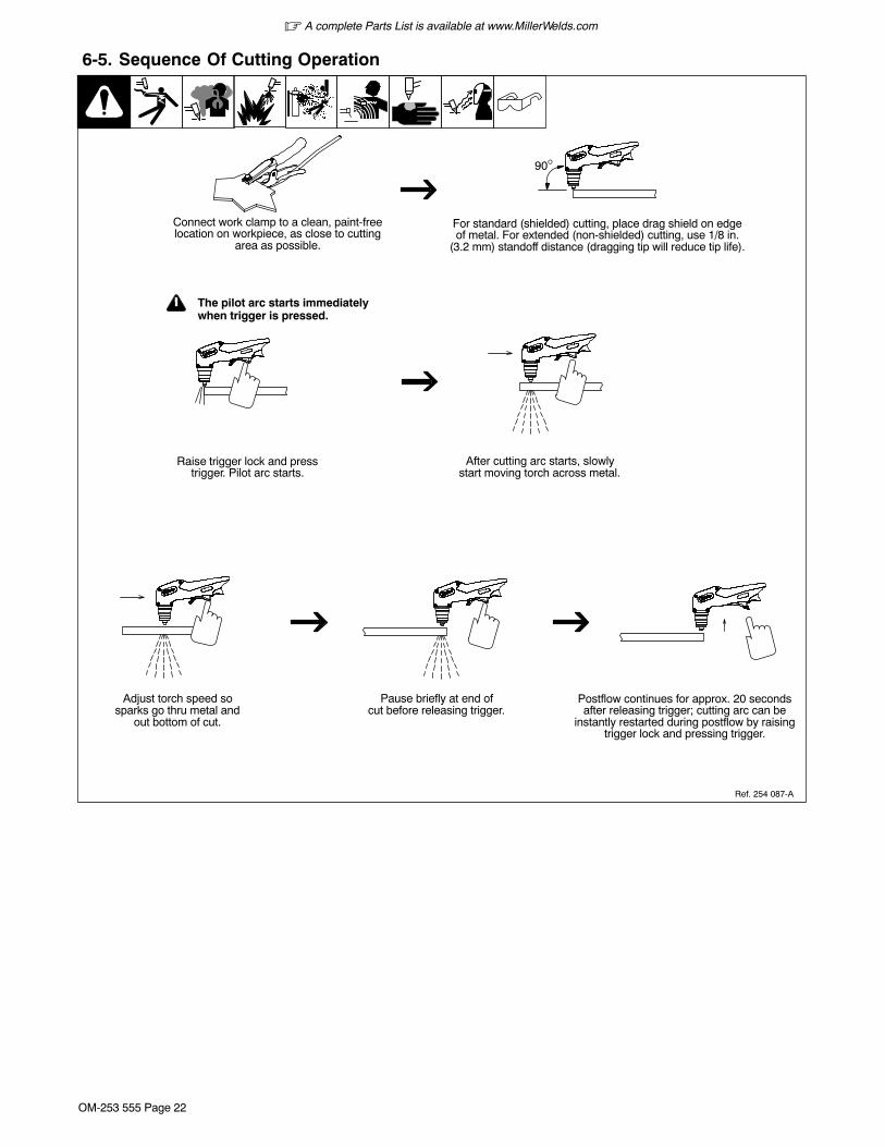
6-5. Sequence Of Cutting Operation
After cutting arc starts, slowlystart moving torch across metal.
Adjust torch speed sosparks go thru metal and
Pause briefly at end ofcut before releasing trigger.
Raise trigger lock and presstrigger. Pilot arc starts.
Postflow continues for approx. 20 secondsafter releasing trigger; cutting arc can be
instantly restarted during postflow by raisingtrigger lock and pressing trigger.
! The pilot arc starts immediatelywhen trigger is pressed.
For standard (shielded) cutting, place drag shield on edgeof metal. For extended (non-shielded) cutting, use 1/8 in.
(3.2 mm) standoff distance (dragging tip will reduce tip life).
Connect work clamp to a clean, paint-freelocation on workpiece, as close to cutting
area as possible.
90°

� A complete Parts List is available at www.MillerWelds.com
OM-253 555 Page 23
Ref. 254 087-A
6-6. Sequence Of Piercing Operation
Maintain approximately 90° torchposition to surface, and continue
cutting.
Release trigger. Postflow continues forapprox. 20 seconds after releasing trigger;
arc can be instantly restarted during postflowby raising trigger lock and pressing trigger.
! The pilot arc starts immediatelywhen trigger is pressed.
Hold torch at approximately 45°to the workpiece. Raise triggerlock and press trigger. Pilot arc
starts.
Connect work clamp to a clean, paint-freelocation on workpiece, as close to cutting
area as possible.
Rotate torch to upright positionapproximately 90° to surface.When arc has pierced through
workpiece, start cutting.
90° 90°
45°

� A complete Parts List is available at www.MillerWelds.com
OM-253 555 Page 24
SECTION 7 − MAINTENANCE & TROUBLESHOOTING
7-1. Routine Maintenance
! Disconnect power before maintaining.
� Maintain more oftenduring severe conditions.
� = Check � = Change = Clean = Replace* To be done by Factory Authorized Service Agent
Reference
EachUse
Section 5-3,7-7
� Gas/Air Pressure � Torch Tip, Electrode,And Shield Cup
EveryWeek Section 7-6
� Shield Cup ShutdownSystem
Every3Months
Section 7-4,9
Damaged Or UnreadableLabels
Air Filter/Regulator Cracked Parts � Gas/Air Hose
� Torch Body, Cable
Every6Months
OR
Inside Unit
7-2. Overload Protection
Ref. 251 808-A
1 Supplementary Protector CB1
CB1 protects unit from overload. IfCB1 opens, unit shuts down.
Reset supplementary protector.1

� A complete Parts List is available at www.MillerWelds.com
OM-253 555 Page 25
7-3. Wrapper Removal
Ref. 251 808-A
! Turn off power, anddisconnect input power plugfrom receptacle or turn off andlockout/tagout line discon-nect device before working onunit.
! Significant DC voltage canremain on capacitors after unitis Off. Check to see that frontpanel lights (LEDs) havestopped flashing and are offbefore removing wrapper.
1 Wrapper
2 Torx Screws (Fine Thread)
Remove Torx screws and slidewrapper off.
Torx 25
Tools Needed:
1
2
Notes

� A complete Parts List is available at www.MillerWelds.com
OM-253 555 Page 26
7-4. Checking Or Replacing Filter Element
! Significant DC voltage canremain on capacitors afterunit is Off. Check to see thatfront panel lights (LEDs)have stopped flashing andare off before removingwrapper.
Turn power Off, and disconnectinput power plug from receptacle.Remove wrapper from unit (seeSection 7-3).
1 Filter Base
2 Filter
3 Filter Cup
Unscrew filter cup from base.
Remove cup.
Unscrew filter element from base.
Check filter element for dirt andmoisture, and replace if necessary.
Be sure that all parts are clean anddry.
Reinstall filter element, and securefilter cup.
Reinstall wrapper.
Ref. 251 808-A / Ref. 804 506-B
1
2
3
Torx 25
Tools Needed:
� A complete Parts List is available at www.MillerWelds.com
OM-253 555 Page 27
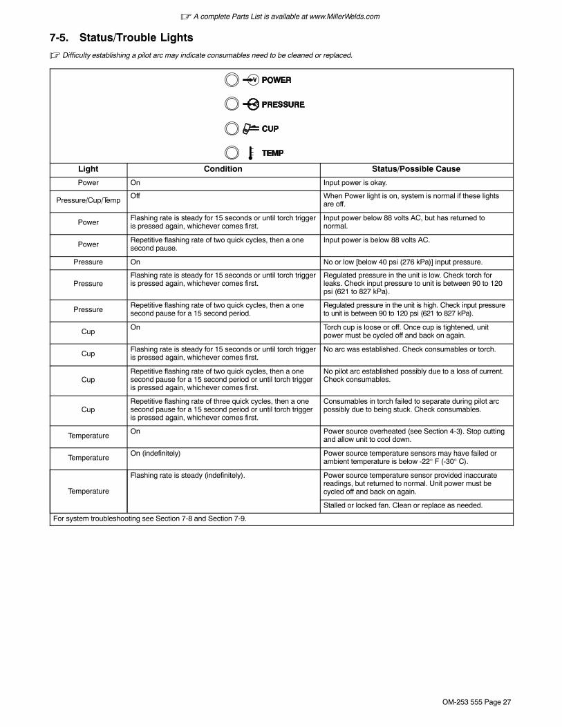
7-5. Status/Trouble Lights
� Difficulty establishing a pilot arc may indicate consumables need to be cleaned or replaced.
Light Condition Status/Possible Cause
Power On Input power is okay.
Pressure/Cup/TempOff When Power light is on, system is normal if these lights
are off.
PowerFlashing rate is steady for 15 seconds or until torch triggeris pressed again, whichever comes first.
Input power below 88 volts AC, but has returned tonormal.
PowerRepetitive flashing rate of two quick cycles, then a onesecond pause.
Input power is below 88 volts AC.
Pressure On No or low [below 40 psi (276 kPa)] input pressure.
PressureFlashing rate is steady for 15 seconds or until torch triggeris pressed again, whichever comes first.
Regulated pressure in the unit is low. Check torch forleaks. Check input pressure to unit is between 90 to 120psi (621 to 827 kPa).
PressureRepetitive flashing rate of two quick cycles, then a onesecond pause for a 15 second period.
Regulated pressure in the unit is high. Check input pressureto unit is between 90 to 120 psi (621 to 827 kPa).
CupOn Torch cup is loose or off. Once cup is tightened, unit
power must be cycled off and back on again.
CupFlashing rate is steady for 15 seconds or until torch triggeris pressed again, whichever comes first.
No arc was established. Check consumables or torch.
CupRepetitive flashing rate of two quick cycles, then a onesecond pause for a 15 second period or until torch triggeris pressed again, whichever comes first.
No pilot arc established possibly due to a loss of current.Check consumables.
CupRepetitive flashing rate of three quick cycles, then a onesecond pause for a 15 second period or until torch triggeris pressed again, whichever comes first.
Consumables in torch failed to separate during pilot arcpossibly due to being stuck. Check consumables.
TemperatureOn Power source overheated (see Section 4-3). Stop cutting
and allow unit to cool down.
TemperatureOn (indefinitely) Power source temperature sensors may have failed or
ambient temperature is below -22° F (-30° C).
Temperature
Flashing rate is steady (indefinitely). Power source temperature sensor provided inaccuratereadings, but returned to normal. Unit power must becycled off and back on again.
Stalled or locked fan. Clean or replace as needed.
For system troubleshooting see Section 7-8 and Section 7-9.

� A complete Parts List is available at www.MillerWelds.com
OM-253 555 Page 28
7-6. Checking Shield Cup Shutdown System
Ref. 253 554-A
1 Torch Shield Cup
Turn Power On and loosen shieldcup. If shutdown system worksproperly, Cup light comes on. If not,immediately turn Off power andhave Factory Authorized ServiceAgent check unit.
If system works properly, retightencup and reset power.
1
� Power must be reset whenever the cup shutdown systemis activated. Always turn Off power when changing orchecking consumables. Do NOT overtighten torchshield cup. Gently finger tighten cup onto torch.
Notes

� A complete Parts List is available at www.MillerWelds.com
OM-253 555 Page 29
7-7. Checking/Replacing Retaining Cup, Tip, And Electrode
! Overtightening will strip threads. Do not overtighten retainingcup during assembly. Do not cross-thread parts causingstripping. Use care during torch assembly and partsreplacement.
! Inspect shield cup, tip, and electrode for wear before cutting or whenever cutting speed has been signifi-cantly reduced. Do not operate torch without a tip or electrode in place. Be sure to use genuine replacementparts.
� A good practice is to replace both the tip and electrode at the same time.
Ref. 253554-A
Turn Off power source.
1 Shield Cup
Remove shield cup. Check cup for cracks,and replace if necessary.
2 Tip
3 Opening
Remove tip. Check tip, and replace if open-ing is deformed or 50% oversize. If inside oftip is not clean and bright, clean with steelwool. Be sure to remove any pieces of steelwool afterwards.
4 Electrode
Check electrode. If center has a pit morethan a 1/16 in. (2 mm) deep, remove and re-place electrode.
5 Swirl Ring
Remove swirl ring. Check ring, and replaceif side holes are plugged.
6 O-Ring
Check O-ring for cracks or worn spots, andreplace if necessary.
Carefully reassemble parts in reverse order.
Make sure this area isclean of any debris.
Make sure swirl ring is clean of anydebris and no holes are obstructed.
! Turn Off power source before checking torchparts.
New
Worn
32
5
1
6
New
Worn
4
1/32 in. (1 mm) to 1/16in. (2 mm) maximum pitdepth depending onacceptable cut quality

� A complete Parts List is available at www.MillerWelds.com
OM-253 555 Page 30
7-8. Troubleshooting Power Source
Trouble Remedy
No pilot arc; difficulty in establishing anarc.
Clean or replace worn consumables as necessary (see Section 7-7).
Check for damaged torch or torch cable.
No cutting output; Power light off; statuslights off; fan motor FM does not run.
Place Power switch in On position.
Place line disconnect device in On position (see Section 5-9).
Check line fuse(s) and replace if needed or reset circuit breakers (see Section 5-9).
Pilot arc working; no cutting output;Power light on; status lights off; fanmotor running.
Be sure work clamp is connected.
Clean or replace worn consumables as necessary (see Section 7-7).
No gas/air flow; Power light on; statuslights off; fan motor running.
Have Factory Authorized Service Agent check for proper torch connections. Check operation of gasvalve AS1, and check gas/air system for leaks. Check filter element (see Section 7-4).
Pressure status light On. Check for sufficient gas/air supply pressure (see Section 5-3).
Check for dirty air filter and replace, if necessary (see Section 7-4).
Check air lines for leaks.
Have Factory Authorized Service Agent check pressure switch and control board.
Cup status light On. Check torch shield cup (see Section 7-6). Reset power switch.
Have Factory Authorized Service Agent check torch.
Temperature status light On. Unit overheating. Allow fan to run; the Trouble light goes out when the unit has cooled.
Have Factory Authorized Service Agent check control board.
Status lights not working. Have Factory Authorized Service Agent check unit.
Power light flashing, status lights off. Reset power switch. If problem continues, have qualified technician check input line power.
Pressure status light flashes. Unit lost pressure (momentarily) while cutting. Check air line for leaks.
Cup status light flashes. Unit lost output while attempting to cut or pilot. Check consumables and torch for wear.
Short tip life. Check and clean drag shield of any slag, particles, and debris.
Check input air pressure.

� A complete Parts List is available at www.MillerWelds.com
OM-253 555 Page 31
7-9. Troubleshooting Torch
Trouble Remedy
Arc goes on and off while cutting. Torch travel speed too slow; increase travel speed (see Section 6-5). Clean or replace torch consumablesas necessary (see Section7-7). Be sure work clamp is securely attached to workpiece.
Arc goes out while cutting. Be sure work clamp is securely attached to workpiece. Make sure tip is on or near [1/16 in. (1.6 mm) to1/8 in. (3.2 mm)] workpiece (see Section 6-4). Clean or replace torch consumables as necessary (seeSection 7-7).
Sparks come out top of cut or cut is notclean.
Torch travel speed too fast; reduce travel speed (see Section 6-4). Clean or replace torch consumablesas necessary (see Section 7-7). Be sure work clamp is securely attached to workpiece. Unit not capableof cutting metals thicker than rating (see Section 6-2).
Trouble lights are on; unit has no cuttingoutput.
Check torch consumables. Check for gas/air flow at torch. Check air supply connection and pressure tounit and torch. Reset unit Power switch. Have Factory Authorized Service Agent check torch andconnections inside unit.
Notes

OM-253 555 Page 32
SECTION 8 − ELECTRICAL DIAGRAM
Figure 8-1. Circuit Diagram
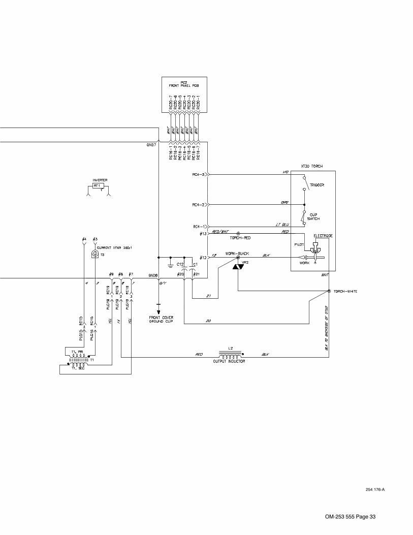
OM-253 555 Page 33
254 176-A
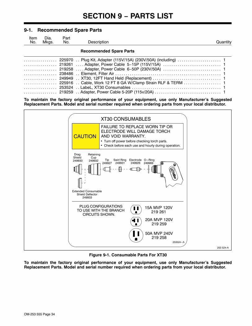
OM-253 555 Page 34
SECTION 9 − PARTS LIST
9-1. Recommended Spare Parts
DescriptionPartNo.
Dia.Mkgs.
ItemNo.
Recommended Spare Parts
Quantity
225970 Plug Kit, Adapter (115V/15A) (230V/50A) (including) 1. . . . . . . . . . . . . . . . . . . . . . . . . . . . . . . . . . . . . . .219261 Adapter, Power Cable 5−15P (115V/15A) 1. . . . . . . . . . . . . . . . . . . . . . . . . . . . . . . . . . . . . . . . . . . . . . . .219258 Adapter, Power Cable 6−50P (230V/50A) 1. . . . . . . . . . . . . . . . . . . . . . . . . . . . . . . . . . . . . . . . . . . . . . . .238486 Element, Filter Air 1. . . . . . . . . . . . . . . . . . . . . . . . . . . . . . . . . . . . . . . . . . . . . . . . . . . . . . . . . . . . . . . . . . . . .249949 XT30, 12FT Hand Held (Replacement) 1. . . . . . . . . . . . . . . . . . . . . . . . . . . . . . . . . . . . . . . . . . . . . . . . . . .225916 Cable, Work 12 FT 8 GA W/Clamp Strain RLF & TERM 1. . . . . . . . . . . . . . . . . . . . . . . . . . . . . . . . . . . .253524 LabeL, XT30 Consumables 1. . . . . . . . . . . . . . . . . . . . . . . . . . . . . . . . . . . . . . . . . . . . . . . . . . . . . . . . . . . . .219259 Adapter, Power Cable 5-20P (115v/20A) 1. . . . . . . . . . . . . . . . . . . . . . . . . . . . . . . . . . . . . . . . . . . . . . . . . .
To maintain the factory original performance of your equipment, use only Manufacturer’s SuggestedReplacement Parts. Model and serial number required when ordering parts from your local distributor.
253 524-A
253524-A
CAUTION
XT30 CONSUMABLES
PLUG CONFIGURATIONSTO USE WITH THE BRANCH
CIRCUITS SHOWN.
15A MVP 120V219 261
20A MVP 120V219 259
50A MVP 240V219 258
FAILURE TO REPLACE WORN TIP ORELECTRODE WILL DAMAGE TORCHAND VOID WARRANTY.�
�
Turn off power before checking torch parts.
Check before each use and hourly during operation.
DragShield249930
Extended ConsumableShield Deflector
249933
RetainingCup
249932 Tip249927
Electrode249926
Swirl Ring249931
O-Ring249969
Figure 9-1. Consumable Parts For XT30
To maintain the factory original performance of your equipment, use only Manufacturer’s SuggestedReplacement Parts. Model and serial number required when ordering parts from your local distributor.

OM-253 555 Page 35
1 249 970 Torch Handle Kit (1)2 249 971 Torch Trigger
Microswitch (1). . . . . . . . . . . . . . .3 249 957 Leads, 12 ft (1)4 252 938 Torch Body Kit (1)5 249 972 Torch Trigger Assembly
w/Spring (1)252 951 Grease, Silicone (1)249 949 Torch, Replacement 12 ft (1)
See Figure 9-1 foradditional consumable parts.
1
1
2
3
4
5
ItemNo.
PartNo. Description
Figure 9-2. Torch, XT30
A complete Parts List is available on-line at www.MillerWelds.comTo maintain the factory original performance of your equipment, use only Manufacturer’s SuggestedReplacement Parts. Model and serial number required when ordering parts from your local distributor.

Notes
16 Gauge (.063 in.)
22 Gauge (.031 in.)
24 Gauge (.025 in.)
20 Gauge (.037 in.)
18 Gauge (.050 in.)
14 Gauge (.078 in.)
1/8 in. (.125 in.)
3/16 in. (.188 in.)
1/4 in. (.25 in.)
5/16 in. (.313 in.)
3/8 in. (.375 in.)
1/2 in. (.5 in.)
MATERIAL THICKNESS REFERENCE CHART

Notes
Work like a Pro!
Pros weld and cut
safely. Read the
safety rules at
the beginning
of this manual.

Notes

Warranty Questions?
Call1-800-4-A-MILLERfor your localMiller distributor.
miller_warr 2011−01
Your distributor also givesyou ...
ServiceYou always get the fast,reliable response youneed. Most replacementparts can be in yourhands in 24 hours.
SupportNeed fast answers to thetough welding questions?Contact your distributor.The expertise of thedistributor and Miller isthere to help you, everystep of the way.
Effective January 1, 2011(Equipment with a serial number preface of MB or newer)This limited warranty supersedes all previous Miller warranties and is exclusive with no other
guarantees or warranties expressed or implied.LIMITED WARRANTY − Subject to the terms and conditionsbelow, Miller Electric Mfg. Co., Appleton, Wisconsin, warrants to itsoriginal retail purchaser that new Miller equipment sold after theeffective date of this limited warranty is free of defects in materialand workmanship at the time it is shipped by Miller. THISWARRANTY IS EXPRESSLY IN LIEU OF ALL OTHERWARRANTIES, EXPRESS OR IMPLIED, INCLUDING THEWARRANTIES OF MERCHANTABILITY AND FITNESS.
Within the warranty periods listed below, Miller will repair or replaceany warranted parts or components that fail due to such defects inmaterial or workmanship. Miller must be notified in writing withinthirty (30) days of such defect or failure, at which time Miller willprovide instructions on the warranty claim procedures to befollowed.
Miller shall honor warranty claims on warranted equipment listedbelow in the event of such a failure within the warranty timeperiods. All warranty time periods start on the delivery date of theequipment to the original end-user purchaser, and not to exceedone year after the equipment is shipped to a North Americandistributor or eighteen months after the equipment is shipped to anInternational distributor.
1. 5 Years Parts — 3 Years Labor* Original main power rectifiers only to include SCRs,
diodes, and discrete rectifier modules2. 3 Years — Parts and Labor
* Engine Driven Welding Generators(NOTE: Engines are warranted separately by theengine manufacturer.)
* Inverter Power Sources (Unless Otherwise Stated)* Plasma Arc Cutting Power Sources* Process Controllers* Semi-Automatic and Automatic Wire Feeders* Smith 30 Series Flowgauge and Flowmeter
Regulators (No Labor)* Transformer/Rectifier Power Sources* Water Coolant Systems (Integrated)
3. 2 Years — Parts* Auto-Darkening Helmet Lenses (No Labor)
4. 1 Year — Parts and Labor Unless Specified* Automatic Motion Devices* CoolBelt and CoolBand Blower Unit (No Labor)* External Monitoring Equipment and Sensors* Field Options
(NOTE: Field options are covered for the remainingwarranty period of the product they are installed in, orfor a minimum of one year — whichever is greater.)
* Flowgauge and Flowmeter Regulators (No Labor)* RFCS Foot Controls (Except RFCS-RJ45)* Fume Extractors* HF Units* ICE Plasma Cutting Torches (No Labor)* Induction Heating Power Sources, Coolers, and
Electronic Controls/Recorders* Load Banks* Motor Driven Guns (w/exception of Spoolmate
Spoolguns)* PAPR Blower Unit (No Labor)* Positioners and Controllers* Racks* Running Gear/Trailers* Spot Welders* Subarc Wire Drive Assemblies* Water Coolant Systems (Non-Integrated)* Weldcraft-Branded TIG Torches (No Labor)* Wireless Remote Foot/Hand Controls and Receivers* Work Stations/Weld Tables (No Labor)
5. 6 Months — Parts* Batteries* Bernard Guns (No Labor)* Tregaskiss Guns (No Labor)
6. 90 Days — Parts* Accessory (Kits)* Canvas Covers* Induction Heating Coils and Blankets, Cables, and
Non-Electronic Controls* M-Guns* MIG Guns and Subarc (SAW) Guns* Remote Controls and RFCS-RJ45* Replacement Parts (No labor)* Roughneck Guns* Spoolmate Spoolguns
Miller’s True Blue® Limited Warranty shall not apply to:
1. Consumable components; such as contact tips,cutting nozzles, contactors, brushes, relays, workstation table tops and welding curtains, or parts thatfail due to normal wear. (Exception: brushes andrelays are covered on all engine-driven products.)
2. Items furnished by Miller, but manufactured by others,such as engines or trade accessories. These items arecovered by the manufacturer’s warranty, if any.
3. Equipment that has been modified by any party other thanMiller, or equipment that has been improperly installed,improperly operated or misused based upon industrystandards, or equipment which has not had reasonableand necessary maintenance, or equipment which hasbeen used for operation outside of the specifications forthe equipment.
MILLER PRODUCTS ARE INTENDED FOR PURCHASE ANDUSE BY COMMERCIAL/INDUSTRIAL USERS AND PERSONSTRAINED AND EXPERIENCED IN THE USE ANDMAINTENANCE OF WELDING EQUIPMENT.
In the event of a warranty claim covered by this warranty, theexclusive remedies shall be, at Miller’s option: (1) repair; or (2)replacement; or, where authorized in writing by Miller inappropriate cases, (3) the reasonable cost of repair orreplacement at an authorized Miller service station; or (4) paymentof or credit for the purchase price (less reasonable depreciationbased upon actual use) upon return of the goods at customer’s riskand expense. Miller’s option of repair or replacement will be F.O.B.,Factory at Appleton, Wisconsin, or F.O.B. at a Miller authorizedservice facility as determined by Miller. Therefore nocompensation or reimbursement for transportation costs of anykind will be allowed.
TO THE EXTENT PERMITTED BY LAW, THE REMEDIESPROVIDED HEREIN ARE THE SOLE AND EXCLUSIVEREMEDIES. IN NO EVENT SHALL MILLER BE LIABLE FORDIRECT, INDIRECT, SPECIAL, INCIDENTAL ORCONSEQUENTIAL DAMAGES (INCLUDING LOSS OFPROFIT), WHETHER BASED ON CONTRACT, TORT OR ANYOTHER LEGAL THEORY.
ANY EXPRESS WARRANTY NOT PROVIDED HEREIN ANDANY IMPLIED WARRANTY, GUARANTY ORREPRESENTATION AS TO PERFORMANCE, AND ANYREMEDY FOR BREACH OF CONTRACT TORT OR ANYOTHER LEGAL THEORY WHICH, BUT FOR THIS PROVISION,MIGHT ARISE BY IMPLICATION, OPERATION OF LAW,CUSTOM OF TRADE OR COURSE OF DEALING, INCLUDINGANY IMPLIED WARRANTY OF MERCHANTABILITY ORFITNESS FOR PARTICULAR PURPOSE, WITH RESPECT TOANY AND ALL EQUIPMENT FURNISHED BY MILLER ISEXCLUDED AND DISCLAIMED BY MILLER.
Some states in the U.S.A. do not allow limitations of how long animplied warranty lasts, or the exclusion of incidental, indirect,special or consequential damages, so the above limitation orexclusion may not apply to you. This warranty provides specificlegal rights, and other rights may be available, but may vary fromstate to state.
In Canada, legislation in some provinces provides for certainadditional warranties or remedies other than as stated herein, andto the extent that they may not be waived, the limitations andexclusions set out above may not apply. This Limited Warrantyprovides specific legal rights, and other rights may be available,but may vary from province to province.
ORIGINAL INSTRUCTIONS − PRINTED IN USA © 2011 Miller Electric Mfg. Co. 2011−01
Miller Electric Mfg. Co.An Illinois Tool Works Company1635 West Spencer StreetAppleton, WI 54914 USA
International Headquarters−USAUSA Phone: 920-735-4505 Auto-AttendedUSA & Canada FAX: 920-735-4134International FAX: 920-735-4125
For International Locations Visitwww.MillerWelds.com
Model Name Serial/Style Number
Purchase Date (Date which equipment was delivered to original customer.)
Distributor
Address
City
State Zip
Please complete and retain with your personal records.
Always provide Model Name and Serial/Style Number.
Contact a DISTRIBUTOR or SERVICE AGENCY near you.
Welding Supplies and Consumables
Options and Accessories
Personal Safety Equipment
Service and Repair
Replacement Parts
Training (Schools, Videos, Books)
Technical Manuals (Servicing Informationand Parts)
Circuit Diagrams
Welding Process Handbooks
Contact the Delivering Carrier to:
For Service
Owner’s Record
File a claim for loss or damage duringshipment.
For assistance in filing or settling claims, contactyour distributor and/or equipment manufacturer’sTransportation Department.
Contact your Distributor for:
To locate a Distributor or Service Agency visitwww.millerwelds.com or call 1-800-4-A-Miller
Top Related