


Languages
Pages
Legal

1
SPACE ENGINEERING RESEARCH CENTERSPRING SEMINAR SERIES:
LEAPFROGFebruary 20th 2020
7/21/2020 2
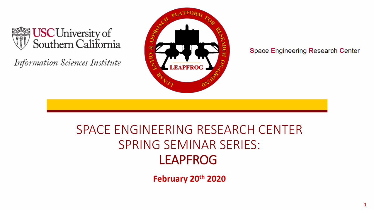
SERC Seminar Series – Spring 2020
February 2020:LEAPFROG: USC’s Flight Tesbted re-thinking Planetary
Landers for Next Generation Exploration
Interested to Join SERC?Fill out Application at
https://www.isi.edu/centers/serc/join_us
7/21/2020 3
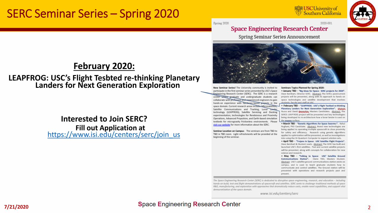
USC’s Space Engineering Research Center: What is it
~200 undergrad, graduate and PhD. students involved in all aspects of hands-on space engineering to-date
• Astronautical Engineering (ASTE)• Bachelor of Science• Bachelor of Science Minor• Master of Science• Engineer• PhD• Graduate Certificate
An academic industry membership run
“Space Engineering Teaching Hospital”
• Information Sciences Institute• Part of USC’s Viterbi School in Marina del Rey,
Arlington, VA, and Waltham, MA• >$80M/year from diverse sponsors• ~300 people, 2/3rds research staff• Facilities for export or restricted research

7/21/2020 4
Topic Presenter
LEAPFROG at a glance
• Introduction, Purpose & Background• Past and Current Mission Architectures• New Research Project Goals• Gen-II LEAPFROG Design
1. Requirements2. Basic Design Characteristics
• Two Research Focus Areas• TVC Systems• Reconfigurable Robotic Arm and Adjoined Tool
• Next Steps for LEAPFROG
• Alan Osmundson• Ishan Puranik• Aloisia Russo
• Michael Augrand• Antariksh Narain/Ishan Puranik
• David Bernacchia/Michael Augrand• Aloisia Russo
• Alan Osmundson

7/21/2020 5
Introduction, Purpose & Background
LEAPFROG (Lunar Entry and Approach Platform For Research On Ground) was started asa multi-semester design-to-flight student hands-on training activity through theAstronautics and Space Technology Division and Information Sciences Institute at theUniversity of Southern California in 2006.
Mass = ~ 23 kgT/W = ~ 1.05 (w/o Payload)Flight Time = Less than 1 min.Payload Capacity = ~ 0.1 kgEngine = JetCat P200Thrust = ~ 230N
7/21/2020 6
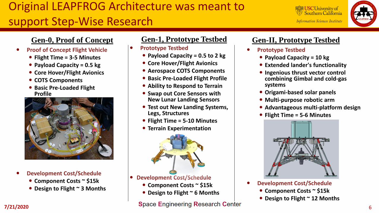
Original LEAPFROG Architecture was meant to support Step-Wise Research
Prototype Testbed Payload Capacity = 0.5 to 2 kg Core Hover/Flight Avionics Aerospace COTS Components Basic Pre-Loaded Flight Profile Ability to Respond to Terrain Swap out Core Sensors with
New Lunar Landing Sensors Test out New Landing Systems,
Legs, Structures Flight Time = 5-10 Minutes Terrain Experimentation
Development Cost/Schedule Component Costs ~ $15k Design to Flight ~ 6 Months
Proof of Concept Flight Vehicle Flight Time = 3-5 Minutes Payload Capacity = 0.5 kg Core Hover/Flight Avionics COTS Components Basic Pre-Loaded Flight
Profile
Development Cost/Schedule Component Costs ~ $15k Design to Flight ~ 3 Months
Gen-0, Proof of Concept Gen-1, Prototype Testbed Gen-II, Prototype Testbed Prototype Testbed
Payload Capacity = 10 kg Extended lander's functionality Ingenious thrust vector control
combining Gimbal and cold-gas systems
Origami-based solar panels Multi-purpose robotic arm Advantageous multi-platform design Flight Time = 5-6 Minutes
Development Cost/Schedule Component Costs ~ $15k Design to Flight ~ 12 Months
7/21/2020 7
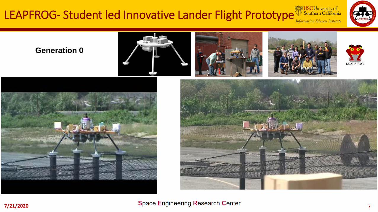
LEAPFROG- Student led Innovative Lander Flight Prototype
Generation 0
7/21/2020 8
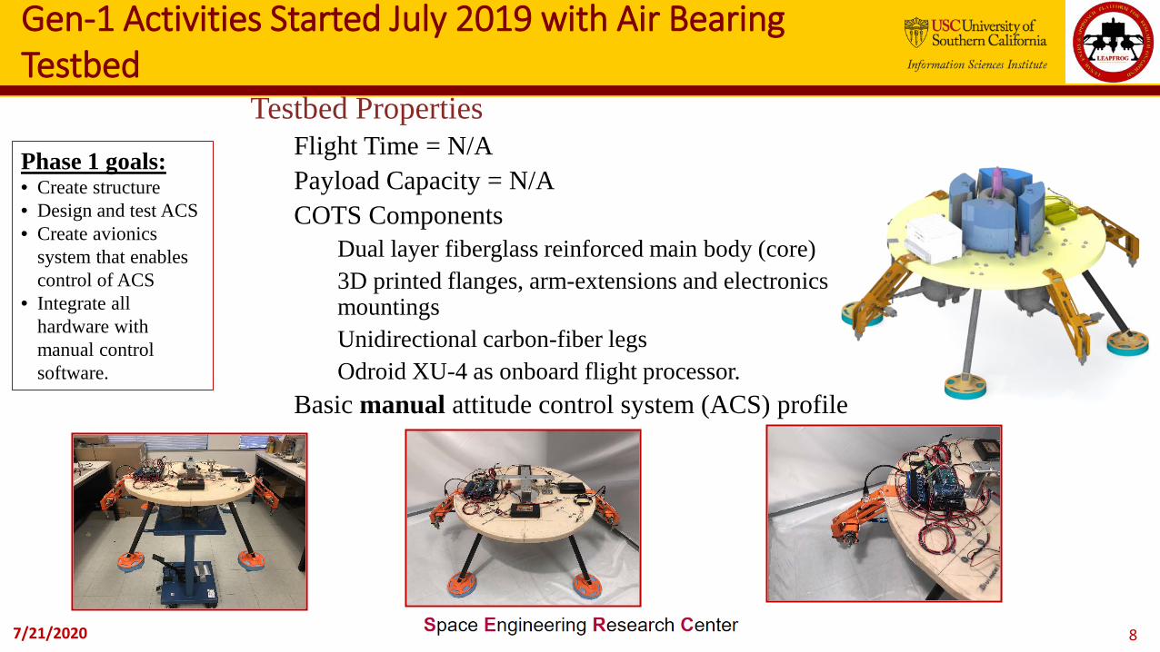
Gen-1 Activities Started July 2019 with Air Bearing Testbed
Testbed PropertiesFlight Time = N/APayload Capacity = N/ACOTS Components
Dual layer fiberglass reinforced main body (core)3D printed flanges, arm-extensions and electronics mountingsUnidirectional carbon-fiber legsOdroid XU-4 as onboard flight processor.
Basic manual attitude control system (ACS) profile
Phase 1 goals:• Create structure• Design and test ACS• Create avionics
system that enables control of ACS
• Integrate all hardware with manual control software.

7/21/2020 9
Gen-1 Initial Testing focused on Cold Gas RCS Changes
7/21/2020 10
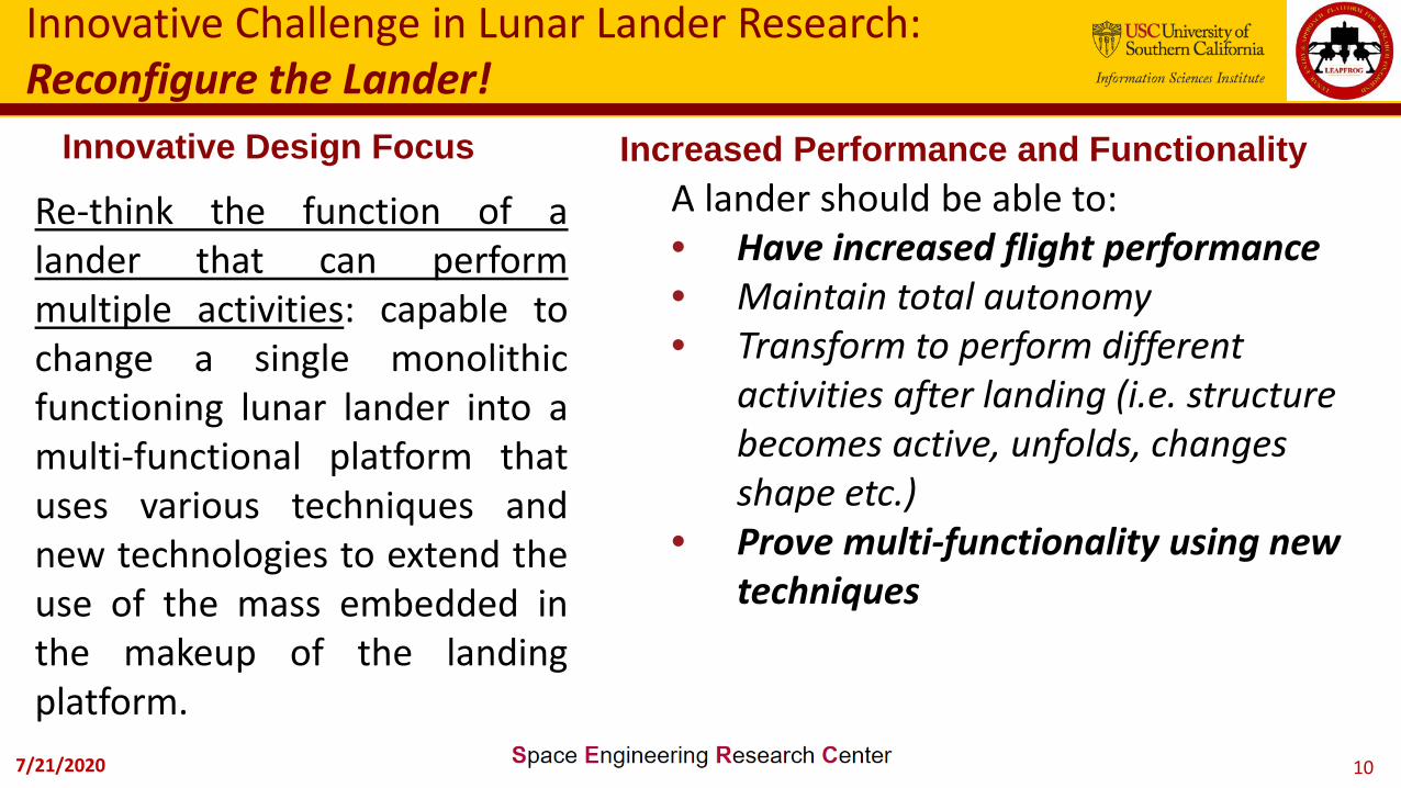
Innovative Challenge in Lunar Lander Research: Reconfigure the Lander!
Re-think the function of alander that can performmultiple activities: capable tochange a single monolithicfunctioning lunar lander into amulti-functional platform thatuses various techniques andnew technologies to extend theuse of the mass embedded inthe makeup of the landingplatform.
Increased Performance and FunctionalityA lander should be able to:• Have increased flight performance• Maintain total autonomy• Transform to perform different
activities after landing (i.e. structure becomes active, unfolds, changes shape etc.)
• Prove multi-functionality using new techniques
Innovative Design Focus
7/21/2020 11
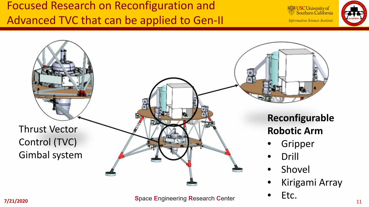
Focused Research on Reconfiguration and Advanced TVC that can be applied to Gen-II
ReconfigurableRobotic Arm• Gripper• Drill• Shovel• Kirigami Array• Etc.
Thrust VectorControl (TVC) Gimbal system

7/21/2020 12
LEAPFROG GEN-II Resultant Design Requirements
LEAPFROG GEN II Performance Upgrades:Mass = ~ 25 kgT/W = ~ 1.2 (w/o Payload)Flight Time = ~5 min.Payload Capacity = ~ 10 kg
Gen-II Component Mass [Kg]
Main structure 8
Engine P-300Pro JetCat 2.7
Fuel 3.9
Gimbal systems 1.486
Linear actuator 1.08 each (multiply by 2)
Electronics 3.5
TOTAL 22.286
7/21/2020 13
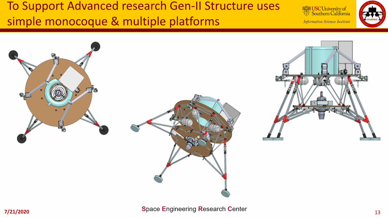
To Support Advanced research Gen-II Structure uses simple monocoque & multiple platforms

7/21/2020 14
Structural elements modeled in NX and Ansys for stability and dynamics

7/21/2020 15
LEAPFROG Gen-II Core System functions
* GNC Sensors to be implemented
** Gimbal Electronics not shown

7/21/2020 16
Avionics uses COTS Processor(s)
Current Circuit DesignIMU Odroid XU4
Relay Board
Grounding Blocks
7/21/2020 17
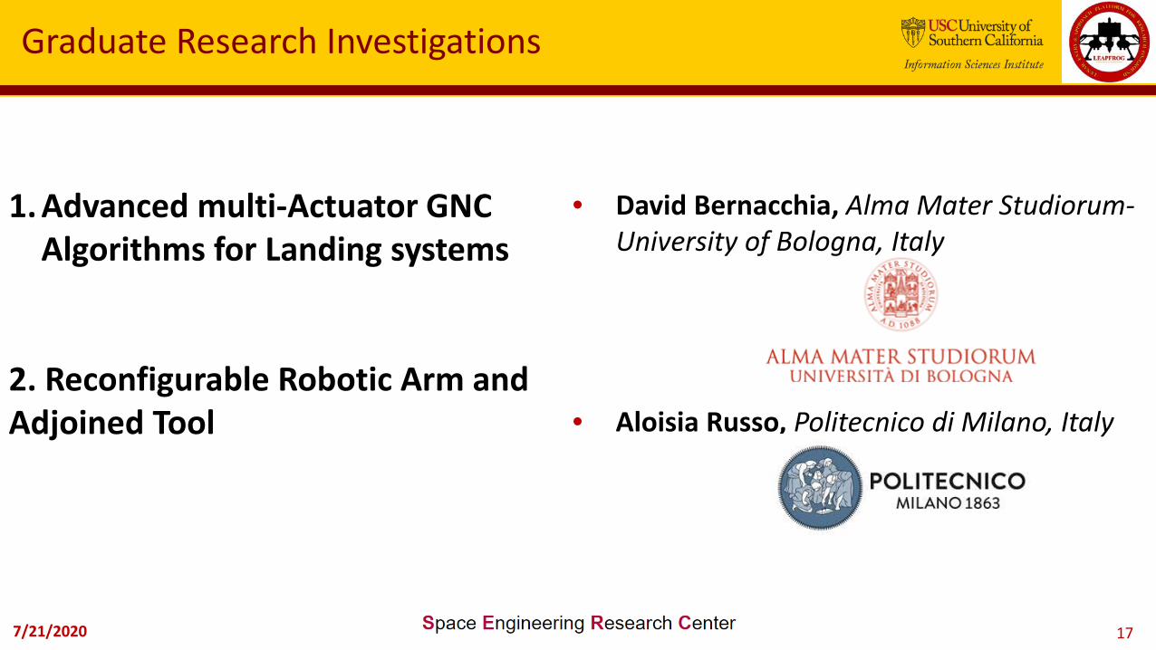
Graduate Research Investigations
1. Advanced multi-Actuator GNC Algorithms for Landing systems
2. Reconfigurable Robotic Arm and Adjoined Tool
• David Bernacchia, Alma Mater Studiorum-University of Bologna, Italy
• Aloisia Russo, Politecnico di Milano, Italy

7/21/2020 18
First Focused Research: Advanced GNC Algorithms for landing systems
Research Challenge: Apply advanced guidance navigation andcontrol algorithms to a multi-actuator landing platform.
Testbed Platform: Gen-2 with both a Thrust Vector Controlsystem and Reaction Control System
Approach: Investigate both linear (traditional) and sliding modecontrol algorithms that can optimize both RCS and TVC during alanders flight.
7/21/2020 19
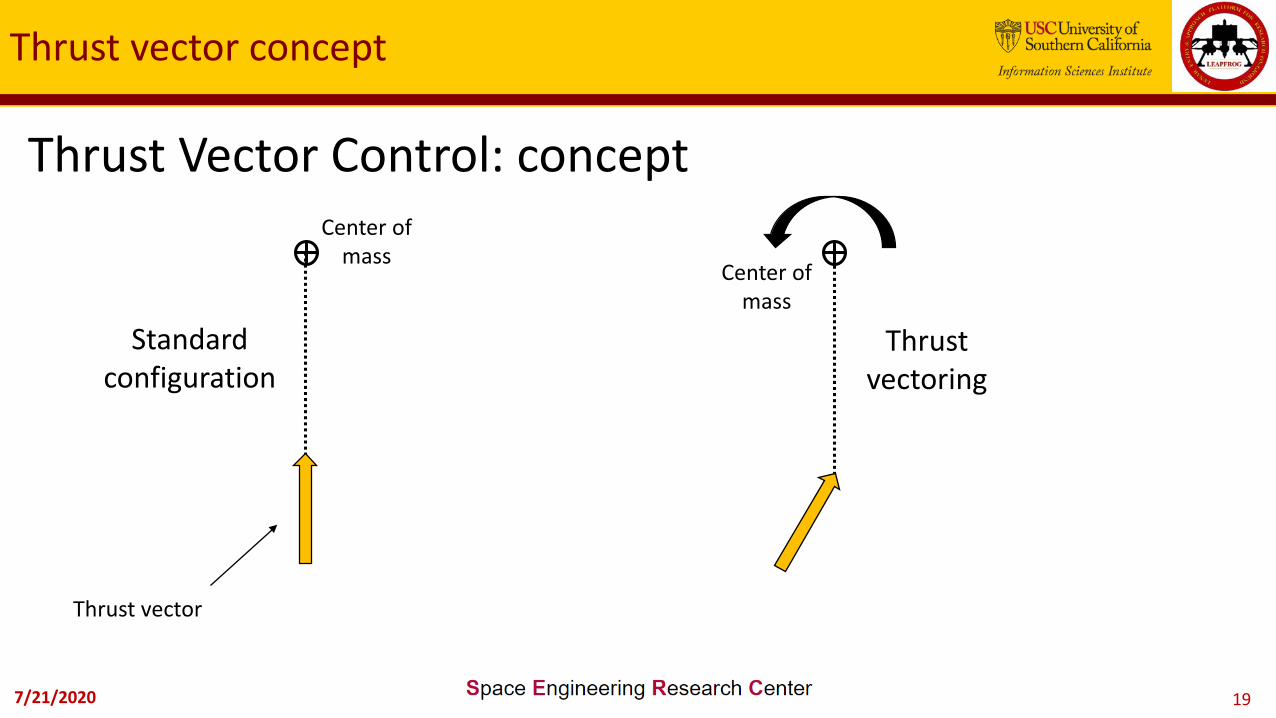
Thrust Vector Control: concept
Standard configuration
Thrust vectoring
Thrust vector
Center of mass
Thrust vector concept
Center of mass
7/21/2020 20
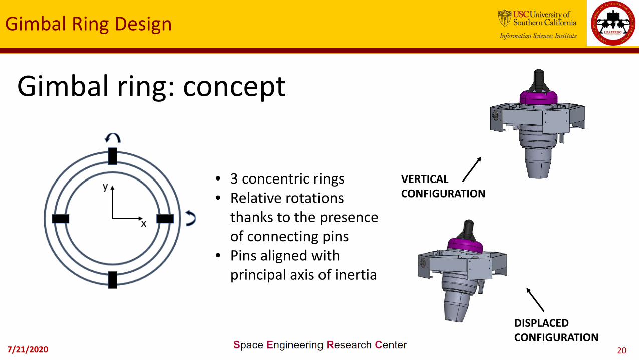
Gimbal ring: concept
• 3 concentric rings• Relative rotations
thanks to the presenceof connecting pins
• Pins aligned with principal axis of inertia
Gimbal Ring Design
VERTICAL CONFIGURATION
DISPLACED CONFIGURATION
7/21/2020 21
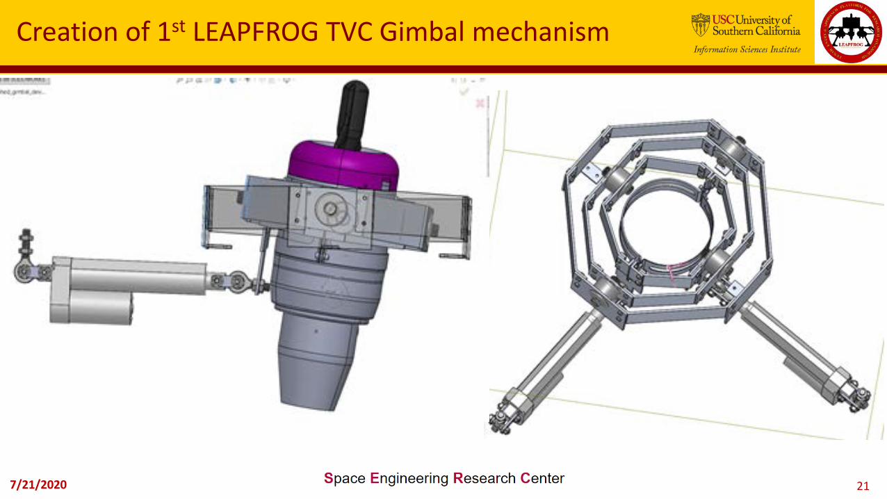
Creation of 1st LEAPFROG TVC Gimbal mechanism
7/21/2020 22
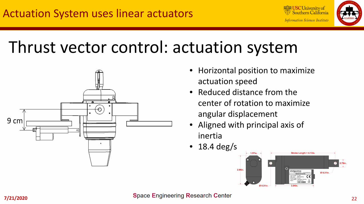
Thrust vector control: actuation system
Actuation System uses linear actuators
• Horizontal position to maximizeactuation speed
• Reduced distance from the center of rotation to maximizeangular displacement
• Aligned with principal axis of inertia
• 18.4 deg/s

7/21/2020 23
Gimbal System Prelim Analysis

7/21/2020 24
Thrust vector control: gimbal angles
Gimbal angles define the optimization variables
• -90 < xi < 90• -5 < delta < 5
7/21/2020 25
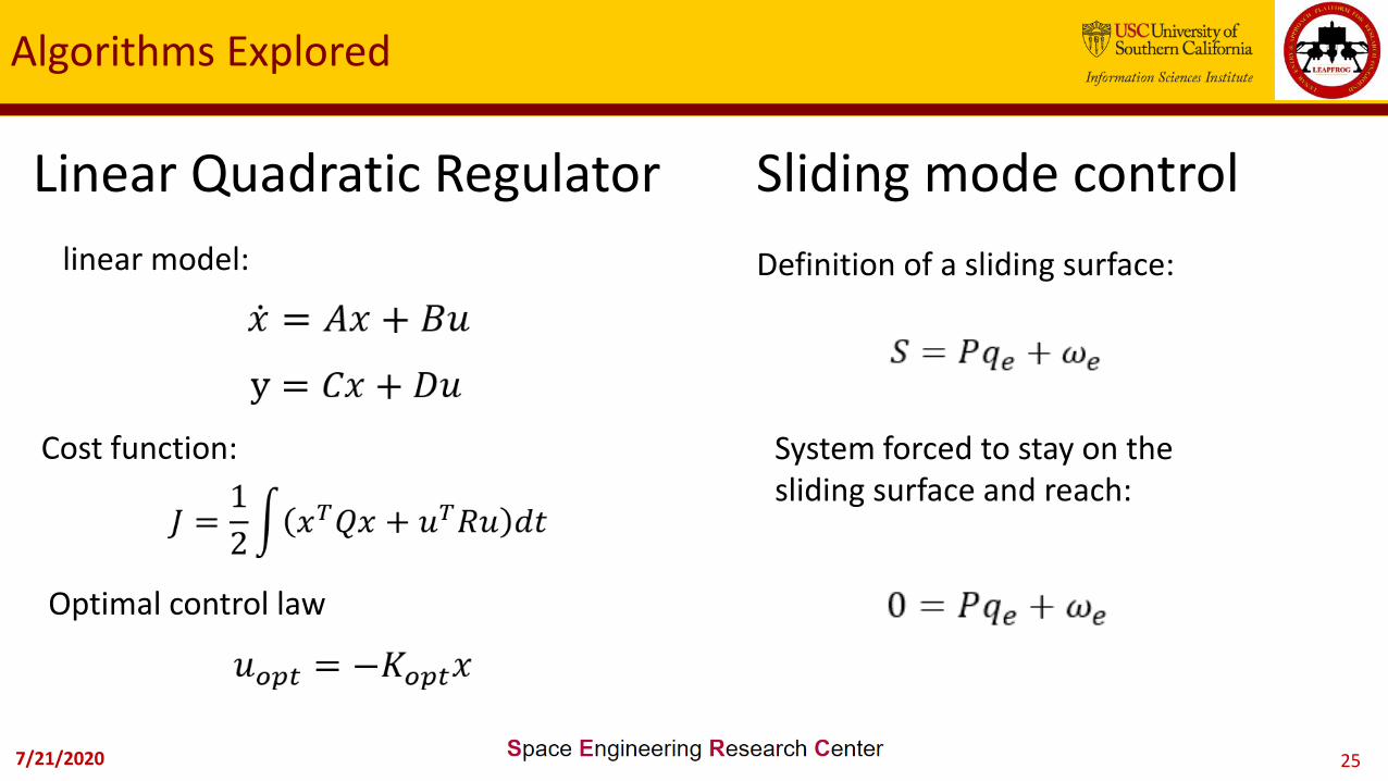
Linear Quadratic Regulator
Algorithms Explored
linear model:
Cost function:
Optimal control law
Sliding mode controlDefinition of a sliding surface:
System forced to stay on the sliding surface and reach:

7/21/2020 26
Linear Quadratic Regulator: ideal case
Linear Quadratic Regulator Results

7/21/2020 27
Sliding mode control: ideal case
Sliding Mode Control Results

7/21/2020 28
Sliding Mode Control results
Sliding mode control: external disturbance

7/21/2020 29
Control block scheme

7/21/2020 30
Second Focused Research: Robotic Reconfiguration
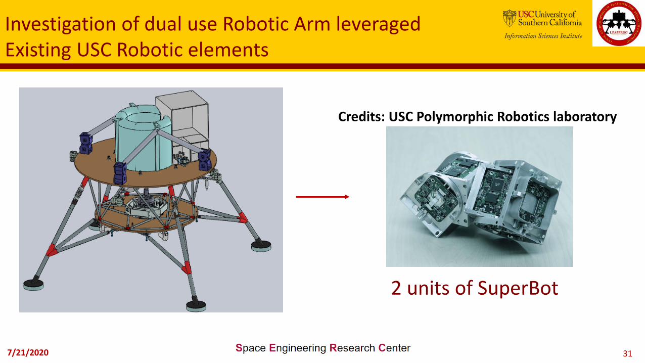
Research Challenge: Design a reconfigurable robotic arm whichcould perform soil activities, sustain a solar panel during the landernon-operative mode and act as a secondary structure on fuel tanks.
Testbed: For robotic arm, simulations; for adjoining tool (solarpanel) use Kirigami based fold/unfolding 3D printed prototype.
Approach: Find the most suitable configuration of the robotic armas well as the most compact and functional design for the on-boardsolar panel.
7/21/2020 31
Investigation of dual use Robotic Arm leveraged Existing USC Robotic elements
2 units of SuperBot
Credits: USC Polymorphic Robotics laboratory

7/21/2020 32
Robotic Arm Basic System block diagram
7/21/2020 33
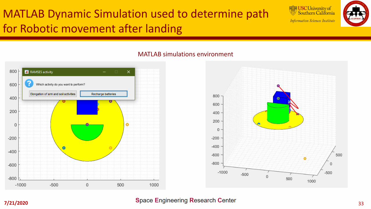
MATLAB Dynamic Simulation used to determine path for Robotic movement after landing
MATLAB simulations environment
7/21/2020 34
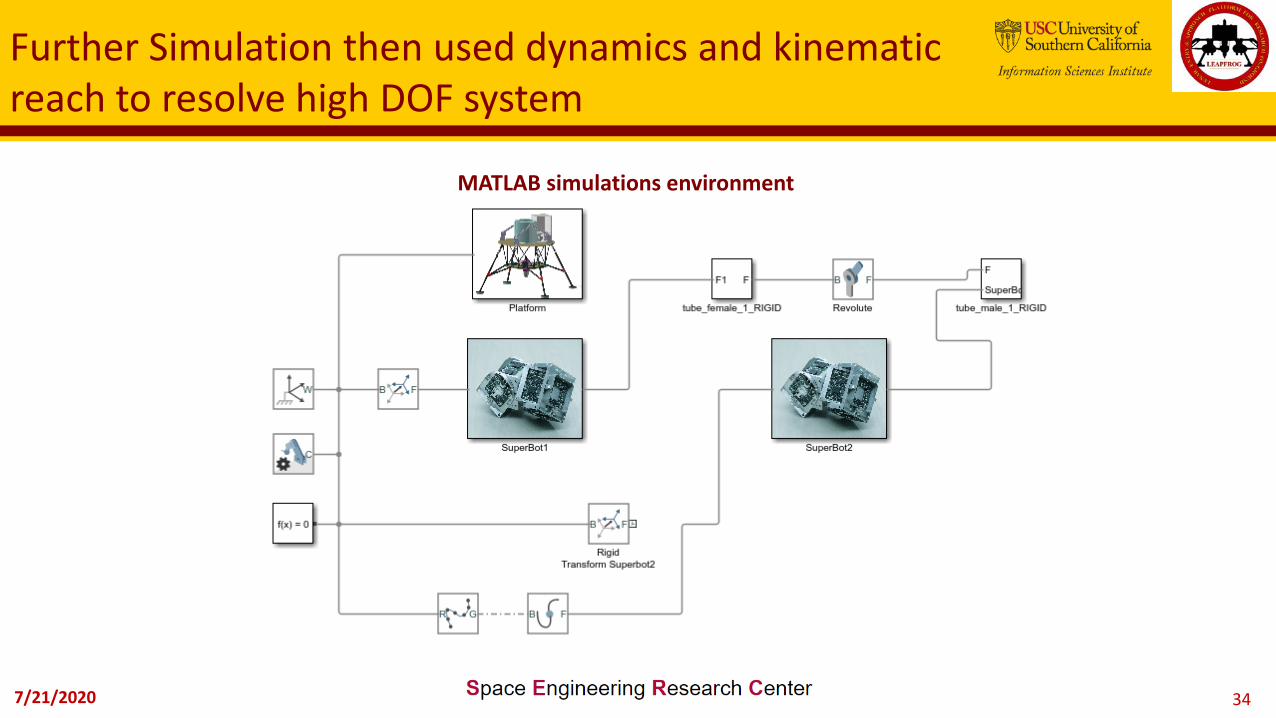
Further Simulation then used dynamics and kinematic reach to resolve high DOF system
MATLAB simulations environment
7/21/2020 35
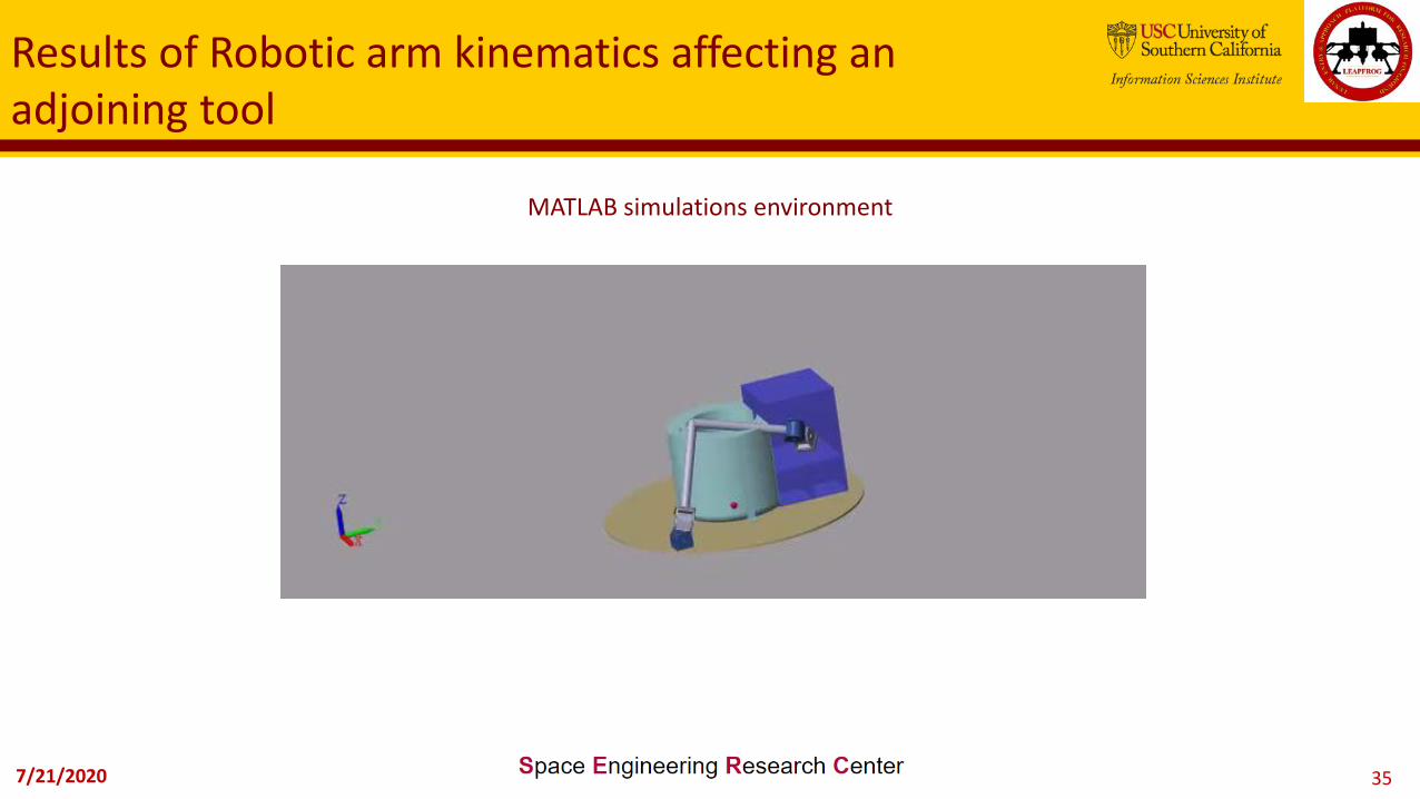
Results of Robotic arm kinematics affecting an adjoining tool
MATLAB simulations environment

7/21/2020 36
Another Reconfiguration Concept for dual use:Kirigami fold structure with thickness
7/21/2020 37
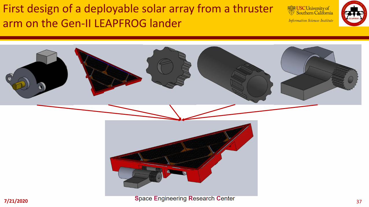
First design of a deployable solar array from a thruster arm on the Gen-II LEAPFROG lander

7/21/2020 38
System Block Diagram of Kirigami
7/21/2020 39
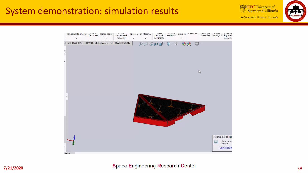
System demonstration: simulation results
7/21/2020 40
Next steps for LEAPFROG
• Complete building of Gen-II structure• Add ACS to Gen-II structure• Build Gimbal mechanism and control
electronics• Build and test first two Tassels and solar panel
simulators• Air Bearing test using the gimbal and ACS
system, validate Sliding Mode Control Algorithms
• Test Avionics for Gen-II with Wi-Fi control• Engine Static Hot Fire• Free flight!• LEAPFROG on the Moon?

7/21/2020 41
“..inspirante ad astra..’’
Join us!
7/21/2020 42
Contacts
POC: Prof. David Barnhart, Directorhttp://[email protected]
310-448-8644
Applications at https://www.isi.edu/centers/serc/join_us
Top Related