


Languages
Pages
Legal


DESIGN AIDS FOR
REINFORCED CONCRETE TO IS : 456-l 978

As in the Original Standard, this Page is Intentionally Left Blank
Design Aids For Reinforced Concrete
to IS : 4564978
BUREAU OF INDIAN STANDARDS BAHADUR SHAH ZAFAR MARC, NEW DLEHI 110 002

SP16:1980 FIRST PUBLISHED SEPTEMBER 1980
ELEVENTH REPRINT MARCH 1999
(Incorporatinp Amendment No. I)
0 BUREAU OF INDIAN STANDARDS
UDC 624.0 12.45.04 (026)
PRICE Rs. 500.00
I’KiNTED 1N INDIA AT VlB,\ PRESS PVT. LTD., 122 DSIDC SHEDS. OKHLA INDL!STRIAL ARtA. PfIASE-I. NEW DELHI 110(!20 AND PI II3LISHED BY I<I!REAI OF INDIAN STANDARDS. NEW DELI11 II0002
FOREWORD
Users of various civil engineering codes have been feeling the need for explanatory hand- books and other compilations based on Indian Standards. The need has been further emphasized in view of the publication of the National Building Code of India 1970 and its implementation. In 1972, the Department of Science and Technology set up an Expert Group on Housing and Construction Technology under the Chairmanship of Maj-Gen Harkirat Singh. This Group carried out in-depth studies in various areas of civil engineering and constr,uction practices. During the preparation of the Fifth Five Year Plan in 1975, the Group was assigned the task of producing a ,Science and Technology plan for research, development and extension work in the sector of housing and construction technology. One of the items of this plan was the production of design handbooks, explanatory handbooks and design aids based on the National Building Code and various Indian Standards and other activities in the promotion of National Building Code. The Expert Group gave high priority to this item and on the recommendation of the Department of Science and Technology the. Planning Commission approved the follow- ing two projects which were assigned to the Indian Standards Institution:
a) Development programme on Code implementation for building and civil engineering construction, and
b) Typification for industrial buildings.
A Special Committee for Implementation of Science and Technology Projects (SCIP) consisting of experts connected with different aspects (see page viii ) was set up in 1974 to advise the IS1 Directorate General in identification and for guiding the development of the work under the Chairmanship of Maj-Gen Harkirat Singh, Retired Engineer-in-Chief, Army Headquarters and formerly Adviser ( Construction) Planning Commission, Government of India. The Committee has so far identified subjects for several explanatory handbooks/compilations covering appropriate Indian Standards/Codes/Specifications which include the following:
Functional Requirements of Buildings Functional Requirements of Industrial Buildings Summaries of Indian Standardsfor Building Materials Building Construction Practices Foundation of Buildings Explanatory Handbook on Earthquake Resistant Design and Construction (IS : 1893
.
Des& %?for Reinforced Concrete to IS : 456- 1978 Explanatory Handbook on Masonry Code Commentary on Concrete Code ( IS : 456 ) Concrete Mixes Concrete Reinforcement Form Work Timber Engineering Steel Code ( IS : 800 ) Loading Code Fire Safety Prefabrication Tall Buildings
,
Design of Industrial Steel Structures Inspection of Different Items of Building Work Bulk Storage Structures in Steel Bulk Storage Structures in Concrete Liquid Retaining Structures
.
Construction Safety Practices Commentaries on Finalized Building Bye-laws Concrete Industrial Structures
One of the explanatory handbooks identified is on IS : 456-1978 Code of practice for plain and reinforced concrete ( third revision). This explanatory handbook which is under preparation would cover the basis/source of each clause; the interpretation of the clause and worked out examples to illustrate the application of the clauses. However, it was felt that some design aids would be of help in designing as a supplement to the explanatory handbook. The objective of these design aids is to reduce design time in the use of certain clauses in the Code for the design of beams, slabs and columns in general building structures.
For the preparation of the design aids a detailed examination of the following handbooks was made :
4
‘4
cl
4
CP : 110 : Part 2 : 1972 Code of practice for the structural use of concrete : Part 2 Design charts for singly reinforced beams, doubly reinforced beams and rectangular columns. British Standards Institution. AC1 Publication SP-17(73) Design Handbook in accordance with the strength design methods of AC1 318-71, Volume 1 ( Second Edition). 1973. American Concrete Institute. Reynolds ( Charles E ) and Steadman ( James C ). Reinforced Concrete Designer’s Handbook. 1974. Ed. 8. Cement and Concrete Association, UK. Fintel ( Mark ), Ed. Handbook on Concrete Engineering. 1974. Published by Van Nostrand Reinhold Company, New York.
The charts and tables included in the design aids were selected after consultation with some users of the Code in India.
The design aids cover the following:
a) Material Strength and Stress-Strain Relationships; b) Flexural Members ( Limit State Design); c) Compression Members ( Limit State Design ); d) Shear and Torsion ( Limit State Design ); e) Development Length and Anchorage ( Limit State Design ); f) Working Stress Method; g) Deflection Calculation; and h) General Tables.
The format of these design aids is as follows:
a) Assumptions regarding material strength; b) Explanation of the basis of preparation of individual sets of design aids as related
to the appropriate clauses in the Code; and c) Worked example illustrating the use of the design aids.
Some important points to be noted in the use of the design aids are:
4 b)
4 d)
4
vi
The design units are entirely in SI units as per the provisions of IS : 456-1978. It is assumed that the user is well acquainted with the provisions of IS : 456-1978 before using these design aids. Notations as per IS : 456-1978 are maintained here as far as possible. Wherever the word ‘Code’ is used in this book, it refers to IS : 456-1978 Code of practice for plain and reinforced concrete ( third revision ).
Both charts and tables are given for flexural members. The charts can be used con- veniently for preliminary design and for final design where greater accuracy is needed, tables may be used.

f) Design of columns is based on uniform distribution of steel on two faces or on four faces.
g) Charts and tables for flexural members do not take into consideration crack control and are meant for strength calculations cnly. Detailing rules given in the Code should be followed for crack control.
h) If the steel being used in the design has a strength which is slightly different from the one used in the Charts and Tables, the Chart or Table for the nearest value may be used and area of reinforcement thus obtained modified in proportion to the ratio of the strength of steels.
j) In most of the charts and tables, colour identification is given on the right/left-hand corner along with other salient values to indicate the type of steel; in other charts/ tables salient values have been given.
These design aids have been prepared on the basis of work done by Shri P. Padmanabhan, Officer on Special Duty, ISI. Shri B. R. Narayanappa, Assistant Director, IS1 was also associated with the work. The draft Handbook was circulated for review to Central Public Works Department, New Delhi; Cement Research Institute of India, New Delhi; Metallurgical and Engineering Consultants (India) Limited, Ranchi, Central Building Research Institute, Roorkee; Structural Engineering Research Centre, Madras; M/s C. R. Narayana Rao, Madras; and Shri K. K. Nambiar, Madras and the views received have been taken into consideration while finalizing the Design Aids.
vii

.SPECIAL COMMIlTEE FOR IMPLEMENTATION OF SCIENCE AND TECHNOLOGY PROJECTS (SCIP)
Members SEIR~ A. K. BANERJEE
PROF DINESH MOHAN DR S. MAUDOAL DR M. RAMAIAH SHRI T. K. SARAN SHRI T. S. VEDAGIRI DR ‘H. C. VISVESVARAYA SHRI D. AJITHA SIMHA
(Member Secrewv)
. . . Vlll
Chairman MAJ-GEN HARKIRAT SINGH
W-51 Greater Kailash I, New Delhi 110048
Metallurgical and Engineering Consultants (India) Limited, Ran&i
Central Building Research Institute, Roorkee Department of Science and Technology, New Delhi Structural Engineering Research Centre, Madras Bureau of Public Enterprises, New Delhi Central Public Works Department, New Delhi Cement Research Institute of India, New Delhi Indian Standards Institution, New Delhi

CONTENTS
Page
LIST OF TABLES M THE EXPLANATORY -TEXT . . . . . . x LIST OF CHARTS . . . . . . xi LIST OF TABLES . . . . . . Xiv
SYMBOLS . . . . . . xvii CONVERSK)N FACTORS . . . . . . xix
1. MATERIAL STRENGTH AND STRESS-STRAIN RELATIONSHIPS 3
1.1 Grades of Concrete 1.2 Types and Grades of Reinforcement 1.3 Stress-strain Relationship for Concrete 1.4 Stress-strain Relationship for Steel
2. FLEXURAL MEMBERS
2.1 2.2 2.3 2.3.1 2.3.2 2.4 2.5
Assumptions Maximum Depth of Neutral Axis Rectangular Sections Under-Reinforced Sections Doubly Reinforced Sections T-Sections Control of Deflection
3. COMPRESSION MEMBERS
3.1 3.2 3.2.1 3.2.2
Axially Loaded Compression Members Combined Axial Load and Uniaxial BendIng Assumptions
3.2.3 3.3 3.4
Stress Block Parameters when the Neutral iAxis Lies Outside the Section Construction of Interaction Diagram Compression Members Subject to Biaxial Bending Slender Compression Members
4. SHEAR AND TORSION
4.1 Design Shear Strength of Concrete 4.2 Nominal Shear Stress 4.3 Shear Reinforcement 4.4 Torsion
. .
. . .
. . .
. . .
. . .
. . .
. . .
. . .
. . .
. . .
. . .
. . .
. . .
. . .
. . .
..*
. . .
. . .
. . .
. . .
. . .
. . .
. . .
. . .
. . .
. . . 3
. . . 3
. . . 4
. . . 4
. . . 9
. . . 9
. . . 9
. . . 9
. . . 10
. . . 12
. . . 14
. . . 14
. . . 99
. . . 99
. . . 99
. . . 100
. . . 101
. . . 101
. . . 104
. . . 106
. . . 175
..* 175
. . . 175
. . . 175 .
. . . 175
ix

Page
5.
5.1
5.2
6.
6.1
6.1.1
6.1.2
6.1.3
6.2
6.3
6.4
7.
7.1
7.2
DEVELOPMENT LENGTH AND ANCHORAGE . . .
Development Length of Bars . . . Anchorage Value of Hooks and Bends . . .
WORKING STRESS DESIGN . . .
Flexural Members . . . Balanced Section . . . Under-Reinforced Section . . . Doubly Reinforced Section . . . Compression Members . . . Shear and Torsion . . . Development Length and Anchorage . . .
DEFLECTION CALCULATION . . .
Effective Moment of Inertia . . . Shrinkage and Creepl)eflections . . .
. . . 183
. . . 183
. . . - 183
. . . 189
. . . 189
. . . 189
. . . 189
. . . 190
. . . 190
. . . 191
1.. 191
. . . 213
. . . 213
. . . 213
LIST OF TABLES IN THE EXPLANATORY TEXT
Table
A
B
C
D
E
F
G H
I J K
L
M
X
Salient Points on the Design Stress Strain Curve for Cold Worked Bars . . . . . .
Values of F for Different Grades of Steel . . . . . .
Limiting Moment of Resistance and Reinforcement Index for Singly Reinforced Rectangular Sections . . . . . .
Limiting Moment of Resistance Factor Mu,ii,/bd’, N/mm2 for Singly. Reinforced Rectangular Sections . . . . . .
Maximum Percentage of Tensile Reinforcement Pt,lim for Singly Reinforced Rectangular Sections . . . ..,
Stress in Compression Reinforcement, fX N/mma in Doubly Reinforced Beams with Cold Worked Bars . . . . . .
Multiplying Factors for Use with Charts 19 and 20 . . . . . . Stress Block Parameters When the Neutral Axis Lies Outside the
Section . . . . . . Additional Eccentricity for Slender Compression Members . . . . , .
Maximum Shear Stress rc,max . . . . . .
Moment of Resistance Factor M/bd’, N/mm” for Balanced Rectangular Section . . . . . .
Percentage of Tensile Reinforcement P1,b.i for Singly Reinforced Balanced Section .*. . . .
Values of the Ratio A,/&, . . . . . .
6
9
10
10
10
13
13
101
106
175
I89
189
190

chart No. PW
FLEXURE - Singly Reinforced Section
1 2 3 4 5 6 7 8 9
10 11 12 13 14 15 16 17 18
CL = 15 N/mm’, fy = 250 N/mm’ Lk - 15 N/mm*, fu = 250 N/mm*
f etr - 15 N/mm*, fr = 250 N/mms
f ck = 15 N/mm*, fy = 415 N/mm*
f Ed - 15 N/mm*, fi - 415 N/mm*
fsk - 15 N/mm*, f, - 415 N/mm*
f ck = 15 N/mm*, fi - 500 N/mm*
f ctr = 15 N/mm*, fy - 500 N/mm*
f & - 15 N/mm*, ’ fv - 500 N/mm*
f & x 20 N/mm*, .fy = 250 N/u&
f & - 20 N/mm*, fy - 250 N/mm%
f ek = 20 N/mm’, f, = 2% N/mm’ fh - 20 N/mm*, I; - 415 N/mm*
fdr I 20 N/mm*, fv - 415 N/mm’
f ck - 20 N/mm*, fy - 415 N/m’
f & - 20 N/mm’, fy - 500 N/mm* fd - 20 N/mm’, fr - 500 N/mm*
hk - 20 N/mm*, & = 500 N/mm*
d- 5 to 30 cm . . . 17 d = 30 to 55 cm .*. 18 d - 55 to 80 cm . . . 19 d= 5 to 30 cm . . . 21 d I 30 to 55 cm . . . 22 d-55 to 80 cm . . . 23 d== 5 to 30 cm . . . 25 d = 30 to 55 cm . . . 26 d-55 to 80 cm . . . 27 ,d P 5 to 30 cm . . . 29 d - 30 to 55 cm . . . 30 d = 55 to 80 cm . . . 31 d- 5 to 30 cm . . . 33 d-30 to 55 cm . . . 34 d- 55 to 80 cm . . . 35 d= 5 to 30 cm . . . 37 d-30 to 55 cm . . . 38 d I 55 to 80 cm . . . 39
FLEXURE - Doubly Reinforced Section
19 fr I 250 N/mm’, d-d’ - 20 to 50 cm 20 fr I 250 N/mm*, d-d’ - 50 to 80 cm
. . . . . . 41
. . . . . . 42
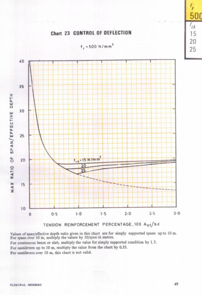
CONTROL OF DEFLECTION
21 fr - 250 N/mm’ . . . . . . 43 22 fr I 415 N/mm’ . . . ,.. 44 23 fi - 500 N/mm’ . . . . . . 45
LIST OF CHARTS
AXIAL COMPRESSION
24 h - 250 N/mm’ . . . .“. 109 25 ft - 415 N/mm’ . . . . . . 110 26 A-5OON/mm’ . . . . . . 111
xi
Chart No.
27 f, = 250 N/mm% d’/D = 0.05 28 fi = 250 N/mms d’/D = 0.10 29 h I 250 N/mm9 d’/D = 0.15 30 fv LI 250 N/mm9 d’/D = 020 31 fr = 415 N/mm9 d’/D = 0.05 32 fu = 415 N/mm9 d’/D - 0.10 33 fr PD 415 N/mm9 d’/D P 0.15 34 fy - 415 N/mm9 d’/D - 0.20 35 fr - 508 N/mm9 d’/D = 0.05 36 fr - 500 N/mm4 d’/D = 0.10 37 fr = 500 N/mm9 d’/D = 0.15 38 fy - 500 N/mm3 d’/D - 0.20
39 J, I) 250 N/mm* d’/D - 0.05 40 .fx I 250 N/mm” d’/D = 0.10 41 fy = 250 N/mm9 d’/D = 0.15 42 fy - 250 N/mm2 d’lD = 0.20 43 fy II 415 N/mm9 d’/D = 0.05 44 fr P 415 N/mm9 d’/D c 0.10 45 fr I 415 N/mm9 d’/D = 0.15 46 fr - 415 N/mm9 d’/D = 0.20 47 fy = 500 N/mm3 d’/D P 0.05 48 f, - 500 N/mm9 d’/D = 0.10 49 fv - 500 N/mm’ d’lD = 0.15 50 fu = 500 N/mm9 d’/D = 0.20
COMPRESSION WlTH BENDlNG - Circular Section
51 fx - 250 N/mm9 d’/D = 0.05 52 fv P 250 N/mm2 d’/D = 0.10 53 fy = 250 N/mm’ d’/D = 0.15 54 fr = 250 N/mm’ d’/D = 0.20 55 fy P 415 N/mm9 d’/D = 0.05 56 fr - 415 N/mm9 d’!D = 0.10 57 fy = 415 N/mm’ d’/D = 0.15 58 fy - 415 N/mm9 d’/D I= 0.20 59 fi - 500 N/mm9 d’/D = 0.05 60 fu - 500 N/mm” d’/D = 0.10 61 h-500 N/mm* d’/D = 0.15 62 fv-500 N/mm* d’/D = 020
63 64 65
Values of Puz for Compression Members . . . . . . Biaxial Bending in Compression Members . . . . . . Slender Compression Members - Multiplying Factor k for . . . Additional Moments
Page COMPRESSION WITH BENDING - Rectangular Section -
Reinforcement Distributed Equally on Two Sides
. . .
. . .
. . .
. . .
. . .
1..
. . .
. . .
. . .
. . .
. . .
. . .
. . . 112
. . . 113
. . . 114
. . . 115
. . . 116
. . . 117
. . . 118
. . . 119
. . . 120
. . . 121
. . . 122
. . . 123
COMPRESSION WITH BENDING - Rectangular Section - Reinforcement Distributed Equally on Four Sides
. . . . . . 124
. . . . . . 125
. . . . . . 126
. . . . . . 127
. . . . . . 128 . . . . . . 129 . . . . . . 130 . . . . . . 131 . . . . . . 132 . . . . . . 133 . . . . . . 134 . . . . . . 135
. . .
. . .
. . .
. . .
. . .
. . .
. . .
. . .
. . . .
. . .
. . .
. . .
. . . 136
. . . 137
. . . 138
. . . 139 . . . 140 . . . 141 . . . 142 i . . 143 . . . 144 . . . 145 . . . 146 . . . 147
148 149 150
xii
ClUWt No.
TENSION WITH BENDING - Rectangular Section - Reinfomment Distributed Equally on Two Sides
66 h - 250 N/mm’ 67 fr - 250 N/mm’ 68 fr - 415 N/mm’ 69 & = 415 N/mm* 70 h - 415 N/mm’ 71 /r - 415 N/mm’ 72 II-=5OON/llltII’
73 h-5OON/IIUU’
74 h-SOON/mm’ 75 &-so0 N/lIlOI’
TENSION WITH BENDING - Rectangular Section - Reinforcement Distributed Equally on Four Sides
76 77 78 79 80 81 82 83 a4 85
86 87 88 89 90
‘Pl 92
f, - 250 N/mm’ d’/D - 0.05 and 010 . . . . . . fr - 250 N/mm* d’/D - 0.15 and 020 . . . .,. /r - 415 N/mm’ d’/D = 0.05 . . . . . .
/r I 415 N/mma d’/D P 0.10 . . . . . . fr - 415 N/mm’ al/D - 0.15 . . . . . . fr = 415 N/mm’ d’/D - 090 . . . . . .
h-5OON/mm’ d’/D = 0.05 . . . . . .
Jt-5OON/lIllII’ d’/D = 0.10 . . . . . . fr - 500 N/mm* d’/D - 0.15 . . . . . .
A-5OON/IUlll’ d*/D = 020 . . . . . .
Axial Compiession (Working Stress Design) 0, - 130 N/mm* . . . Axial Compression (Working Stress Design) am - 190 N/mm* . . . Moment of Inertia of T-Beams . . . Effective Moment of Inertia for Calculating Deflection . . . Percentage, Area and Spacing of Bars in Slabs . . . Effective Length of Columns - Frame Restrained .Against Sway . . . Effective Length of Columns - Frame Without Restraiht to Sway
d’/D = @l5 and 020 . . . . . .
d’/D -0.05 and 010 . . . . . .
d’/D - @OS . . . . . .
d’/D a 0.10 . . . . . .
d’/D P 0.15 . . ., ..,
d’/D - 020 . . . . . .
d’/D - 0.05 . . . . . .
d’/D = 010 . . . . . .
d’/D - 0.15 . . . . . .
d’/D - O-20 . . . . . .
Page
151 152 153 154 155 156 157 158 159 160
161 162 163 164 165 166 l6i l68 169 170
193 194 215 216 217 218 219
. . . xul
LIST OF TABLES Table No. Page
FLEXURE - Reinforcement Percentage, pI for Singly Reinforced Sections
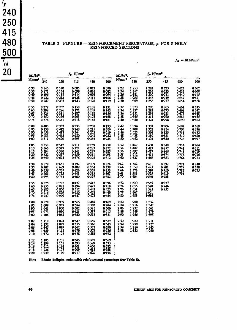
1 fft - 15 N/mm’ ...... 47 2 f CL = 20 N/mm’ ...... 48 3 f CL - 25. N/mm* ...... 49 4 fd = 30 N/mm’ ...... 50
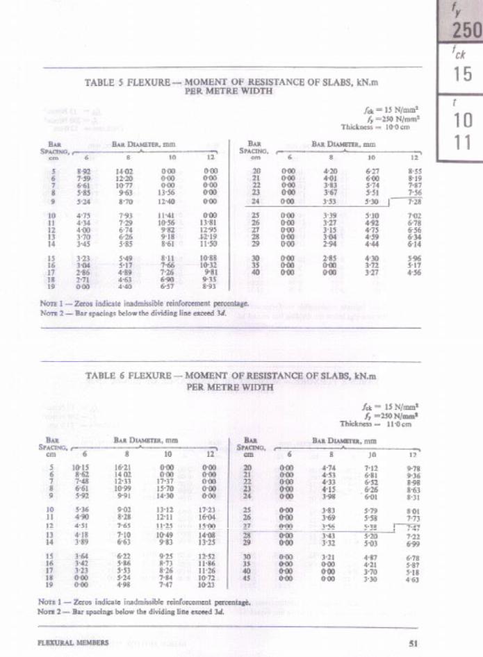
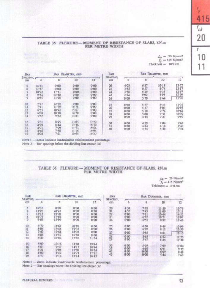
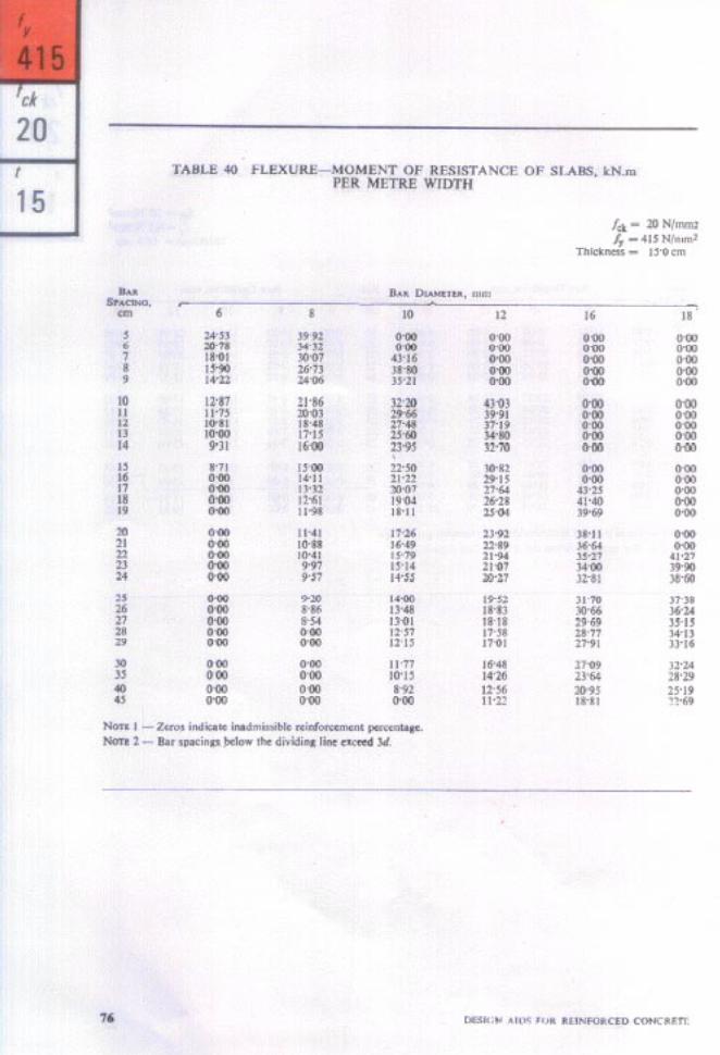
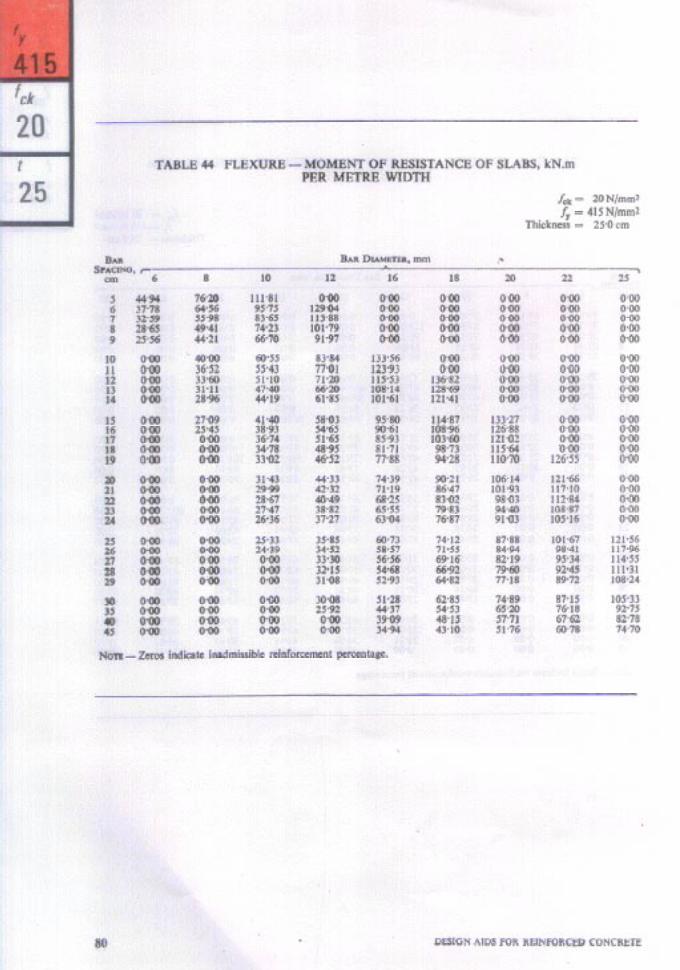
FLEXURE - Moment of Resistance of Slabs, kN.m Per Metre Width
5 6 7 8 9
10 11 12 13 14 15 16 17 18 19 20 21 22 23 24 25 26 27 28 29 30 31 32 33 34
fd - 15 N/mm’ /r- 250 N/mm* Thickness - 10.0 cm f ck- 15 N/llIHl’ fy- 250 N/mm* Thickness - 11.0 cm fdr - 15 N/mm* fr I 250 N/mm* Thickness = 120 cm fdr-15 N/mm’ fy- 250 N/mm* Thickness - 13.0 cm f & - 15 N/mm’. fy w 250 N/mm* Thickness = 14.0 cm Id-15 N/mm’ f,- 250 N/mm’ Thickness - 15.0 cm fd - 15 N/mm* fy- 250 N/mm* Thickness - 175 cm fck- 15 N/mm’ fy- 250 N/mm* Thickness = 20.0 cm fd - 15 N/mm* fi - 250 N/mm* Thickness - 22.5 cm fck - ,15 N/mm* fy - 250 N/mm* Thickness = 25.0 cm fck - 15 N/mm* fy - 415 N/mm* Thickness - 10.0 cm
2: f :: :rGI i- - 415 415 N/mm* N/mm* Thickness Thickness - - 11.0 120 cm cm fd - 15 N/mm* fy I 415 N/mm* Thickness .- 13.0 cm fd - 15 N/mm* fv I 415 N/mm* Thcikness - 140 cm f ck - 15 N/mm* f, - 415 N/mm* Thickness - 15.0 cm fck = 15 N/mm* fv- 415 N/mm* Thickness - 17.5 cm fdt - 15 N/mm* fr - 415 N/mm* Thickness - 20.0 cm fsk- 15 N/mm’ fy E 415 N/mm* Thickness I 225 cm fa- 15 N/m* fy = 415 N/mm* Thickness - 25.0 cm f clr-m N/mm* $, - 250 N/mm* Thickness - 10.0 cm f ck - 20 N/mm’ f, - 250 N/mm* Thickness - 11.0 cm f clr-mN/=’ &I - 250 N/mm* Thickness - 12.0 cm fck -2ON/mm* h - 250 N/mm* Thickness - 13.0 cm f: z $ :\=I 2 - I 250 250 N/mm* N/mm* Thickness Thickness - - 15.0 14.0 cm cm
fd - 20 N/m+ h I 250 N/mm* Thickness - 17.5 cm fck - 20 N/mm* fr - 250 N/mm* Thickness I 20.; cm f& - 20 N/mm’ fy - 250 N/mm* Thickness - 22.5 cm fck - 20 N/mm’ f, I 250 N/mm* Thickness - 25.0 cm,
. . . 51
. . . 51
. . . 52 . . . 52 . . . 53 . . . 53 . . . 54 . . . 55 . . . 56 . . . 57 . . . 58 . . . 58 . . . 59 . . . 59 . . . 60 . . . 61 . . . 62 . . . 63 . . . 64 . . . 65 . . . 66 . . . 66 . . . 67 . . . 67 . . . 68 . . . 68 a*- 69
. . . 70 . . . 71 . . . 72
xiv

Table NO.
35 36 37 38 39 40 41 42 43 44
f ck - 20 N/mm2 h - 415 N/mm2 Thickness - 100 cm fti - 20 N/mm2 h I 415 N/mm2 Thickness - 110 cm 1; - 20 N/mm2 h - 415 N/mm2 Thickness - 12.0 cm
- 415 N/mm2 Thickness - 13.0 cm - 415 N/mm2 Thickness - 14.0 cm
f ,+ - 20 N/mm2 f, - 415 N/mm2 Thickness - 15.0 cm fck - 20 N/mm2 fy - 415 N/mm2 Thickness - 175 cm
- 415 N/mm2 2: 1: i/z: i - 415 N/mm2
Thickness - 200 cm Thickness - 225 cm
f ck - 20 N/mm2 fy - 415 N/mm2 Thickness - 25.0 cm
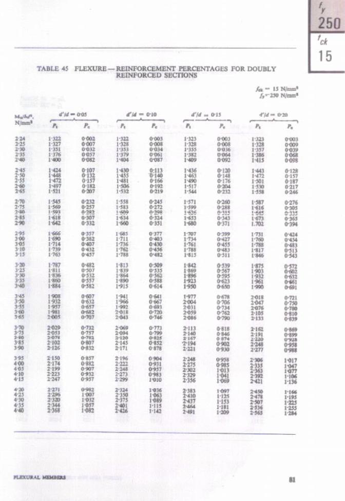
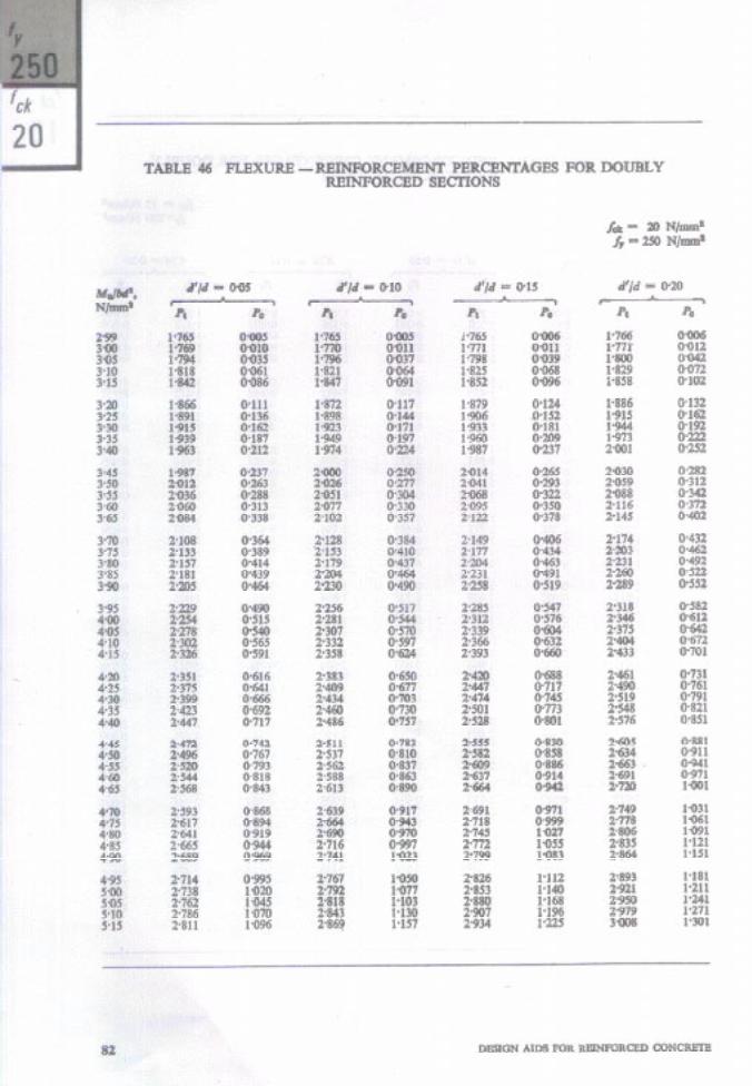
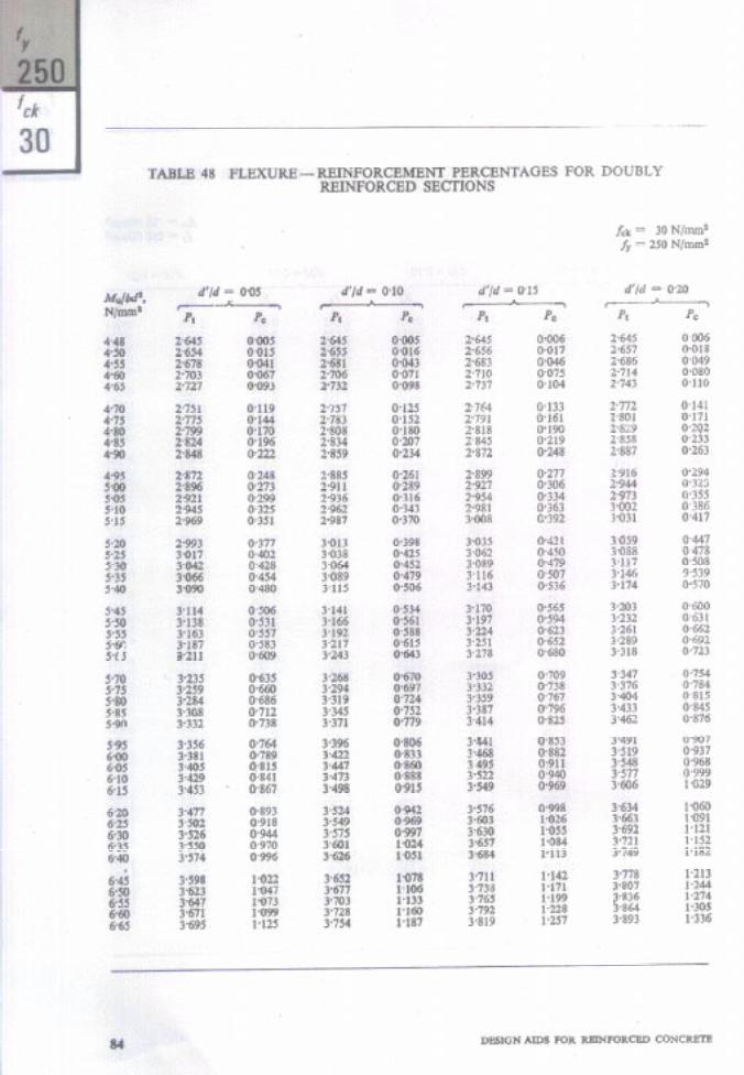
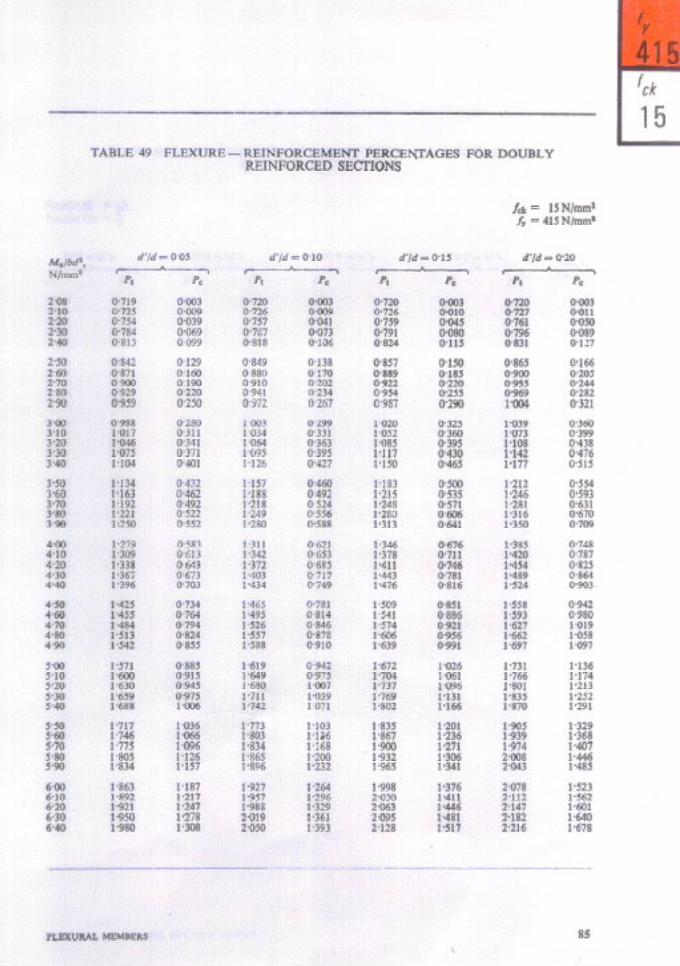
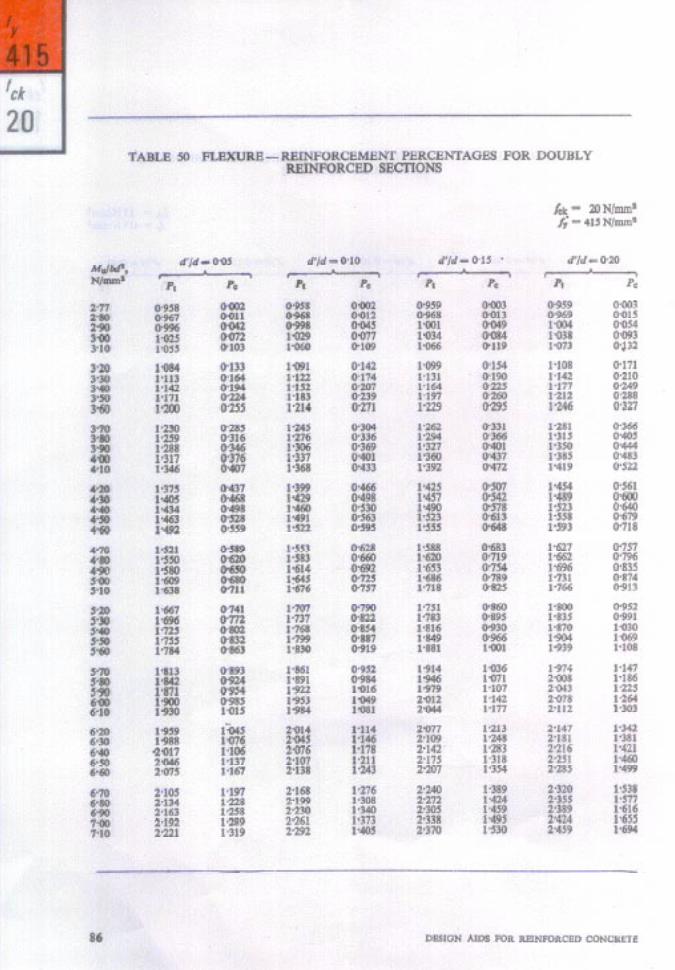
FLEXURE - Reinforcement Percentages for Doubly Reinforced Sections
45 46 47 48 49 50 51 52 53 54 55 56
f & - 15 N/mm2 fr - 250 N/mm2 . . . fr - 250 N/mm2 . . . & - 250 N/mm2 . . .
f;k - 30 N/mm2 fr P 250 N/mm2 . . . f ek- 15 N/mm2 fy I 415 N/mm’ . . .
fy I 415 N/mm2 . . . fr - 415 N/mm2 . . .
fck - 30 N/mm2 fu - 415 N/mm2 . . . fdr - 15 N/mm2 fr - 500 N/mm2 . . .
fck \- 20 N/mm2 fY I: 500 N/mm2 . . . f ck = 25 N/mm2 fy - 500 N/mm2 . . .
f ck - 30 N/mm2 fr-5OON/r.llm2 . . .
. . .
. . .
. . .
. . .
. . .
. . .
. . . . . . . . . . . .
. . .
. . .
. . .
. . .
. . .
. . .
. . .
. . .
. . .
. . .
. . .
. . .
73 73 74 74 75 76 77 78 79 80
81 82 83 84 85 86 87 88 89 90 91 92
57 58 59
60
61 62 63
FLEXURE - Limiting Moment of Resistance Factor, Mo,u,&,# /a, for Singly Reinforced T-beams N/mm*
fv - 250 N/mm’ . . . . . . fy - 415 N/mm= . . . ..* fy - 500 N/mm’ . . . . . .
Slender Compression Members - Values of P, . . . . . .
Shear - Design Shear Strength of Concrete, rc, N/mm* . . . . . . Shear - Vertical Stirrups . . . . . . Shear - Bent-up Bars . . . . . .
93 94 95
171
178 179 179
DEVELOPMENT LENGTH 64 Plain Bars . . . . . . 184 65 Deformed bars, fu P 415 N/mm* . . . . . . 184 66 Deformed bars, fr - 500 N/mm* . . . . . . La5
67 Anchorage Value of Hooks and Bends . . . 2.. 186
2 70 71
WORKING STRESS METHOD - FLEXURE - Moment of Resistance Factor, M/bd’, N/mm’ for Singly Reinforced Sections
a* - 5-O N/mm* . . . . . . u,bc - 7.0 N/mm’ . . . . . . uca - 8.5 N/mm’ . . . .*. ucbc - 10.0 N/mm* . . . . . .
195
:: 198
xv
Table No.
72 73 74 75 76 77 78 79
uck- 5.0 N/mm1 aa - 140 N/mm8 . . . acbs- 79 N/mms w I 140 N/mm’ . . . oti - 8.5 N}mn’ an I 140 N/mm’ . . . a&C- 10.0 N/mm* au - 140 .N/J& . . . ati I 5.0 N/m& u,, - 230 N/mm’ . . . aa - 7.0 N/mm* au P 230 N/inn+ . . . oca - 8.5 v/mm’ a,( - 230 N/mm’ . . . oek - 10.0 N/mm* ust - 230 N/mm’ . . .
WORKING STRJZSS METHOD-SHEAR
. . . . . . . . . . . . . . . . . . . . .
. . . .
80 81 82
Permiklble Shear Stress in Concrete rc, N/mm* . . . . . . Vertical Stirrups . . . . . . Bent-up Bars . . . . . .
WORKING STRESS METHOD - DEVELOPMENT LENGTH
83 Plain Bars . . . 84 Deformed Bars - uat - 230 N/mm*, e - 190 N/mm’ . . . 85 Deformed Bars - u,, - 275 N/mm*, uc - 190 N/mm’ . . .
86 Moment of Inertia - Values of b@/l2 000 . . .
87 &Id - 095 . . . . . . 88 d’ld - 090 . . . . . . 89 d’jd - 015 . . . . . . 90 d’ld - 020 . . . ..I
91 d’/d I 005 92 d’/d - 0.10
93 d’/d - 0.15 94 d’jd = 020
95 Areas of Given Numbers of Bars in cm* . . . . . . 96 Areas of Bars at Given Spacings . . . . . . 97 Fixed End Moments for Prismatic Beams . . . . . . 98 Detlection Formulae for Prismatic Beams . . . . . .
WORKING STRESS DESIGN - FLEXURE - Rchforccmcnt Percentages for Doubly Reinforced S&ions
MOMENT OF INERTIA OF CRACKED SECTION-Values of Ir/
DEPTH OF NEUTRAL &US - Values of n/d by Elastic Theory
1.. . . . 225 l . . . . . 226 . . . . . . 227 . . . . . . 228
221
222
223
224
229 230 a31 232
xvi
SYMBOLS
AC
4 A*
AC A I”
A so
act 6
b
br
bw
b,
D
Di
d
d’,d’
d,
EC
ES
ha
C.Y
f ck
= Area of concrete I Gross area of section = Area of steel in a column or in a
singly reinforced beam or slab - Area of compression steel = Area of stirrups DC Area of additional tensile
reinforcement = Deflection due to creep = Deflection due to shrinkage = Breadth of beam or shorter
dimensions of a rectangular column
= Effective width of flange in a T-beam
= Breadth of web in a T-beam = Centre-to-centre distance between
corner bars in the direction of width
I Overall depth of beam or slab or diameter of column or large1 dimension in a rectangular column or dimension of a rectangular column in the direction of bending
LI Thickness of flange in a T-beam - Effective depth of a beam or slab = distance of centroid of com-
pression reinforcement from the extreme compression fibre of the concrete section
G Centre to centre distance between comer bars in the direction of depth
= Modulus of elasticity of concrete = Modulus of elasticity of steel P Eccentricity with respect to major
axis (xx-axis) = Eccentricity with respect to
minor axis (yy-axis) = Minimum eccentricity = Compressive stress in concrete at
the level of centroid of compression reinforcement
= Charircteristic compressive strength of concrete
E Flexural tensik strength (modulus of rupture) of concrete
= Stress in steel - Compressive stress in steel
corresponding to a strain of 0402
= Stress in the reinforcement nearest to the tension face of a member subjected to combined axial load and bending
= Cytrteristic yield strength of
P Design yield strength of steel = Effective moment of inertia P Moment of inertia of the gross
section about centroidal axis, neglecting reinforcement
= Moment of inertia of cracked section
= Flexural stiffness of beam := Fkxural stiffness of column
= Constant or coefficient or factor = Development length of bar
= Length of column or span of beam
= Effective length of a column, bending about xx-axis
= Effective length of a column, bending about yy-axis
= Maximum moment under service loads
- Cracking moment = Design moment for limit state
Design (factored moment) M u3h-n - Limiting moment of resistance of
a singly reinforced rectangular beam
Mu, e Design moment about xx-axis
MUY a Design moment about &-axis M”l, = Maximum uniaxial moment
capacity of the section with axial load, bending about xx-axis
xvii
&I - Maximum uniaxial moment capacity of the section with axial load, bending about yy-axis
Mel - Equivalent bending moment MU, - Additional moment, MU - Mn,tim
in doubly reinforced beams Mu,timrr= Limiting moment of resistance
m
P
pb
P”
P
PC
PC
Ptr
ST
T”
V
VS
V&l VW
x
of a T-beam = Modular ratio = Axial load - Axial load corresponding to the
condition of maximum compressive strain of 0903 5 in concrete and OQO2 in the outermost layer of tension steel in a compression member
= Design axial load for limit state design (factored load)
P Percentage of reinforcement - Percentage of compression
reinforcement, 100 A,,/bd let Percentage of tension reinforce-
ment, -l,OO Ast/bd - Additional percentage of tensile
reinforcement ’ doubly reinforced beams, ‘I”00 A,t,/bd
- Spacing of stirrups - Torsional moment due to
factored loads - Shear force I Strength of shear reinforcement
(working stress design) = Sbear force due to factored loads = Stren
8h of shear reinforcement
imit state design) = Dept;: neutral axis at service
Xl = Shorter dimension of the stirrup &I = Depth of neutral axis at the
limit state of collapse Xu,mox = Maximum depth of neutral axis
in limit state design
Yc = Distance from centroidal axis of gross section, neglecting reinforcement, to extreme fibre in tension
Yl = Longer dimension of stirrup z = Lever arm a P Angle
Yr - Partial safety factor for load
Ym - Partial safety factor for material strength
t = Creep strain in concrete ecbc - Permissible stress in concrete in
bending compression 6X = Permjssible stress in concrete in
direct compression 01 = Stress in steel bar es 3: Permissible stress in steel in
compression
011 = Permissible stress in steel in tension
es, I Permissible stress in shear reinforcement
7Y P Nominal shear stress
7bd P Design bond stress
k - Shear stress in concrete
‘5w - Equivalent shear stress
Q,mu - Maximum shear stress in concrete with shear reinforcement
8 i Creep coefficient
9 - Diameter of bar
. . . XVlll
CONVERSION FACTORS
To Convert into Conversely
Mu&ply by Multiply by
(1) I
Loads and Forces
(2) (3) (4) -~
Newton Kilonewton
Moments and Torques
Newton metre Kilonewton metre
Stresses
kilogram o-102 0 9.807 Tonne 0.102 0 9.807
kilogram metre o-102 0 9.807 Tonne metre o-102 0 9.807
Newton per mm* Newton per mm’
kilogram per mm’ kilogram per cm2
o-102 0 9.807 10.20 O-098 1
xix


As in the Original Standard, this Page is Intentionally Left Blank
1. MATERIAL STRENGTHS AND STRESS-STRAIN RELATIONSHIPS
I.1 GRADES OF CONCRETE
The following six grades of concrete can be used for reinforced concrete work as specified in Table 2 of the Code (IS : 4% 1978*) :
M 15, M 20, M 25, M 30, M 35 and M 40.
The number in the grade designation refers to the characteristic compressive strength, fti, of 15 cm cubes at 28 days, expressed in N/mmZ ; the characteristic strength being defined as the strength below which not more than 5 percent of the test results are expected to fall.
*Code d practice for plain and reinforced concrete ( third revision ).
1.1.1 Generally. Grades ;ti IS and M 20 are used for flexural members. Charts for flexural members and tables for slabs are, therefore, given for these two grades ordy. However, tables for design of flexural members are given for Grades M 15, M 20, M 25 and M 30.
1.1.2 The charts for compression members are applicable to all grades of concrete.
1.2 TYPES AND GRADES OF REINFORCEMENT BARS
The types of steel permitted for use as re- inforcement bars in 4.6 of the Code and their characteristic strengths (specified minimum yield stress or O-2 percent proof stress) are as follows:
Type oj Steel
Mild steel (plain bars)
Mild steel (hot-rolled deform- ed bars)
Medium tensile steel (plain bars)
Medium tensile steel (hot- rolled deformed bars)
High yield strength steel (hot- rolled deformed bars)
High yield strength steel (cold-twisted deformed bars)
Hard-drawn steel wire fabric
Indian Standard
IS : 432 (Part I)-1966* 1
IS : 1139-1966t r I-
IS : 432 (Part I)-1966*>
I IS : 1139-1966t
1
IS : 1139-1966t
IS : 1786-1979$ 7
IS : 1566-19674 and IS : 432 (Part II)-19661
Yield Stress or O-2 Percent Proof Stress
26 z$fm;rni,or bars up to
24 kgf/mm* for bars over 20 mm dia
36 lkfe;i2’ bars up to .
34.5 kgf/mm* for bars over 20 mm’dia up to 40 mm iiia
33 kgf/mm” for bars over 40 mm dia
42.5 kgf/mm2 for all sizes
4 15 N/mm2 for all bar sizes 500 N/mm* for all bar sizes
49 kgf/mm*
Nom-S1 units have been used in IS: 1786-19793; in other Indian Standards. SI units will be adopted in their next revisions.
*Specification for mild steel and medium tensile steel bars and hard-drawn steel wire for concrete reinforcement: Part I Mild steel and medium tensile steel bars (second revision).
tSpecification for hot rolled mild steel, medium tensile steel and high yield strength steel deformed bars for concrete reinforcement (revised).
$Specificatiod for cold-worked steel high strength &formed bars for concrete reinforcement (second WlSiO#).
&+eciiication for hard-drawn steel wire fabric for concrete reinforcement (#rsr revisfon ).
ijSpecification for mild steel and medium tensile steel bars and hard-drawn steel wire for concrete reinforcement: Part II Hard drawn steel wire (second revision).
MATERIAL STRENGTHS AND STRESS-STRAIN RELATIONSHIPS 3

Taking the above values into consideration, most of the charts and tables have been prepared for three grades of steel having characteristic strength& equal to 250 N/mm*, 415 N/mm2 and 500 N/mm2.
1.2.1 If the steel being used in a design has a strength which is slightly diflerent from the above values, the chart or table for the nearest value may be used and the area ofreinforce- ment thus obtained be modi$ed in proportion to the ratio of the strengths.
1.2.2 Five values of fY (includinglthe value for hard-drawn steel wire fabric) have been included in the tables for singly reinforced sections.
1.3 STRESS-STRAIN RELATIONSHIP FOR CONCRETE
The Code permits the use of any appro- priate curve for the relationship between the compressive stress and strain distribution in concrete, subject to the condition that it results in the prediction of strength in subs- tantial agreement with test results [37.2(c) of the Code]. An acceptable stress-strain curve (see Fig. 1) given in Fig. 20 of the Code will form the basis for the design aids in this publication. The compressive strength of con- crete in the structure is assumed to be O-67 fd. With a value of l-5 for the partial safety
factor ym for material strength (35.4.2.1 of the Code), the maximum compressive stress in concrete for design purpose is 0.446 fck (see Fig. I).
1.4 STRESS-STRAIN RELATIONSHIP FOR STEEL
The modulus of elasticity of steel, E,, is taken as 200 000 N/mm2 (4.6.2 of the Code). This value is applicable to all types of reinforcing steels.
The design yield stress (or 0.2 percent proof stress) of steel is equal to fr/ym. With a value of l-15 for ym (3.5.4.2.2 of the Code), the design yield stress fv stress-strain relations tp for steel in tension 1.
becomes 0#87 f,. The
and compression is assumed to be the same.
For mild steel, the stress is proportional to strain up to yield point and thereafter the strain increases at constant stress (see Fig. 2). For cold-worked bars, the stress-strain relationship given in Fig. 22 of the Code will
I/ / .I
I a.002 0’001
STRAIN
FIG. 1 DESIGN STRKSS-STRAIN CURVE FOR CONCRETE
. 200000 N/mm’
? --
STRAIN
FIG. 2 STRESS-STRAIN CURVE FOR MILD STEEL
be adopted. According to this, the stress is proportional to strain up to a stress of 0.8 fY. Thereafter, the stress-strain curve is defined as given below:
Stress hu#aslic~ srrain O*SOfy Nil 0.85 fr OQOOl 0*9ofy 0.0% 3 0*9sf, o*ooo 7 0.975 fy 0~0010 l-O& 0.002 0
The stress-strain curve for design purposes is obtained by substituting fYe for fY in the above. For two grades of cold-worked bars with 0.2 percent proof stress values of 415 N/mms and 500 N/mm2 respectively, the values of total strains and design stresses corresponding to the points defined above are given in Table A (see page 6). The stress- strain curves for these two grades of cold- worked bars have been plotted in Fig. 3.
4 DESIGN AIDS FOR REINFORCED CONCRETE

T < 2.
500
450
400
350
300
250
200
150
100
50
0
1
so0
m2 soo/
‘iv’
UC/l
0 0.001 o-002 0.003 o-004 0*005
STRAIN
FIG. 3 STRESS-STRAIN CURVES FOR COLD-WORKED STEELE
MATERIAL SrRENGTHS AND STRESS-STRAIN RELATIONSHIPS 5
‘1.0
‘mnl
1-n

TABLE A SALIENT POINTS ON THE DESlGN STRESS-STRAIN CURVE GOR COLD-WORKED BARS
( Chse 1.4 )
STRESS LEVEL f, 0 415 N/mm’ fy = 500 N/mm8 f-- * > ,_-.-k b
Strain Stress Strain Stress (1) (‘1 (3) (4) (5)
N/mm* N/mm*
0.80 fyd 090144 288.1, woo174 347.8 0.85 fyd 0031 63 306.7 0.001 95 369.6 0.90&l 0~00192 324.8 0.002 26 391.3 0’95 fyd 0032 4 I 342.8 0.002 77 413.0 0.975 fyd 0.002 76 351.8 0.003 12 423.9 l’ofyd 0.003 80 360.9 MO4 17 434.8
NOTE -- Linear interpolation may be done for intermediate values.
6

As in the Original Standard, this Page is Intentionally Left Blank
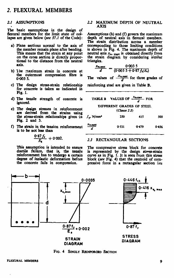
2. FLEXURAL MEMBERS
2.2 ASSUMPTJONS 2.2 MAXIMUM DEPTH OF NEUTRAL . AXIS
The basic assumptions in the design of flexur&l members for the limit state of col- lapse are fciven below (see 37.2 of the Code):
Assumptions (b) and (f’) govern the maximum depth of neutral axis in flexural members.
4 Plane sections normal to the axis of the member remain plane after bending. This means that the strain at any point on the cross section is directly propor- tional to the distance from the neutral RXiS.
W Ihe maximum strain in concrete at the outermost compression fibre is 0903 5.
T& strain distribution across a member corresponding to those limiting conditions is shown in Fig, 4. The maximum depth of neutral axis x,,, - is obtained directly from the strain diagram by considering similar triangles.
x0,,_ 0.003 5 d (0.005 5 f 0.87 f,/&)
d The design stress-strain relationship for concrete is taken as indicated in Fig. 1.
The values of * for three grades of
reinforcing steel are given in Table B.
d) The tensile strength of concrete is TABLE B ignored.
VALUES OF F FOR
e), Tbt design stresses in reinforcement DIFFERENT GRADES OF STEEL
are derived from the strains using (Cfuu.re 2.2)
the stress-strain relationship given -in f,, N/mms 250 415 500 Fig. 2 and 3.
f) The strain in the tension reinforcement 0531 0.479 O-456 is to be not less than
7
2.3 RECTANGULAR SECTIONS
This assumption is intended to ensure The compressive stress block for concrete ductile fail&e, that is, the tensile is represented by the design stress-strain reinforcement has to undergo a certain degree of inelastic deformation before
curve as in Fig. 1. It is. seen from this stress
the concrete fails in compression. block (see Fig. 4) that the centroid of com- pressive force in a rectangular section lies
0*0035
f
X t u,m*a
!zzx + 0*002 E*
STRAIN OIAGRAM
FIQ. 4 SINOLY REINFQRCSD SECTION
O= 87 f-,
STRESS DIAGRAM
FLEXURAL MRMM3R.S

at a distance or U-416 xu (wnlcn nas oecn rounded off to 0.42 xu in the code) from the extreme compression fibre; and the total force of compression is 0.36 fck bxu. The lever arm, that is, the distance between the centroid of compressive force and centroid of tensile force is equal to (d - 0.416 x,). Hence the upper limit for the moment of resistance of a singly reinforced rectangular section is given by the following equation:
M u,lim = O-36& bxu,,, x(d - 0.416 ~u,mu)
Substituting for xu,- from Table B and transposing fdr bd2, we get the values of tie limiting moment of resistance factors for singly reinforced rectangular beams and slabs. These values are given in Table C. The tensile reinforcement percentage, pt,lim corresponding to the limiting moment of resistance is obtained by equating the forces of tension and compression.
Substituting for xu,mPx from Table B, we get the values of Pt,lim fYj& as given in Table C.
TABLE C LIMITING MOMENT OF RESISTANCE AND REINFORCEMENT INDEX FOR SINGLY REl;~&FOR~N~ RECTANGULAR
(Clause 2.3)
j& N/mm* 250 415 500
M*,lhl -- - Lk bd’
0.149 W138 0.133
Plrllrn fy / ck
21.97 19.82 18.87
The values of the limiting moment of resis- tance factor Mu/bd2 for different grades of concrete and steel are given in Table D. The corresponding percentages of reinforcements are given in Table E. These are the maximum permissible percentages for singly reinforced sections.
TABLE D LIMITING MOMENT OF RESISTANCE FAVOR Mu,,im/bd’, N/mm’ FOR
SINGLY REINFC);&yE$sECTANGULAR
(Clause 2.3)
/CL, N/mm’
fy, N/-Y
rK------ 500
15 2.24
Is: 3.45
2.00
3: 2.98 3.73 2.66 3.33 30 4.47 414 3.99
TABLE E MAXIMUM PERCENTAGE OF TENSILE REINFORCEMENT pt,lim FOR
SINGLY REINFStRmTNSRE!aANGW
(c%u.w 2.3)
fdr, /y, Nhm’ N/mm* r b
250 415 u)o
15 1.32
4
1.76 220
;g “0%
2% l.43 YE .
2.3.1 Under-Reinforced Section
Under-reinforced section means a singly reitiorced section with reinforcement per- centage not exceeding the appropriate value given in Table E. For such sections, the depth of neutral axis xu will be smaller than x”,,,,~. The strain in steel at the limit state of collapse will, therefore, be more than 0.87 fy - + 0902 and, the design stress in
E. steel will be 0937 fy. The depth of neutral axis is obtained by equating the forces of tension and compression.
‘G (0.87 fr) - 0.36 fdr b xu
The moment of resistance of the section is equal to the prdduct of the tensile force and the lever arm.
Mu = pG (@87f,) (d - 0,416 xu)
=O*87fy & ( )(
l- 0.4165 )
bd2
Substituting foi $ we get
_ _
x 1 C
- 1.005 &$]bda
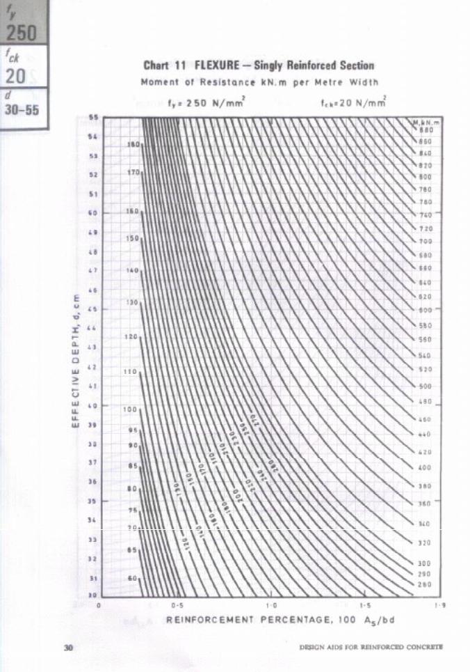
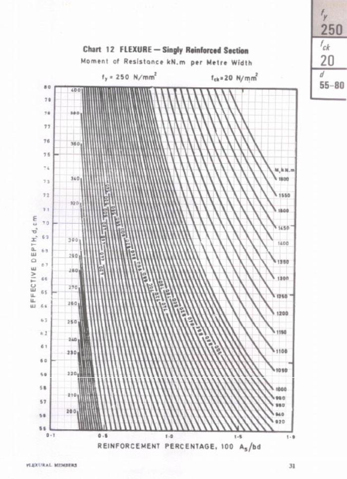
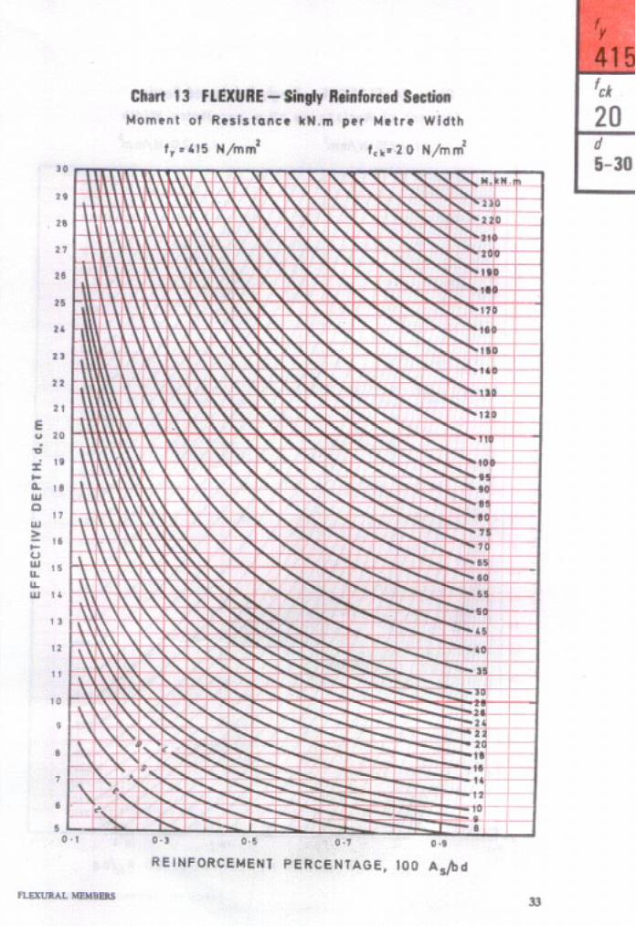
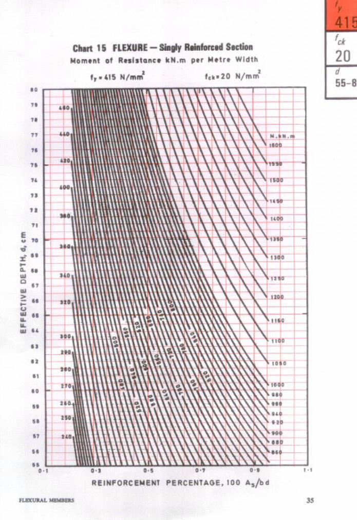
2.3.Z.Z Charts 1 to 28 have been prepared by assigning different values to Mu/b and plotting d versus pt. The moment values in the charts are in units of kN.m per metr$ width. Charts are given for three grades of steel and, two grades of concrete, namely M 15 and M 20, which are most commonly used for flexural members. Tables 1 to 4 cover a wider range, that ‘is, five values of fy and four grades of concrete up to M 30. In these tables, the values of percentage of reinforcement pt have been tabulated against Mu/bd2.
10 DESIGN AIDS FOR WNFORCED CONCRETE

2.3.2.2 The moment of resistance of slabs, with bars of different diameters and spacings are given in Tables 5 to 44. Tables are given for concrete grades M 15 and M 20, with two grades of steel. Ten different thicknesses ranging from 10 cm to 25 cm, are included. These tables take into account 25.5.2.2 of the Code, that is, the maximum bar diameter does not exceed one-eighth the thick- ness of the slab. Clear cover for reinforce- ment has been taken as 15 mm or the bar diameter, whichever is greater [see 25.4.1(d) of the Code]. Jn these tables, the zeros at the top right hand comer indicate the region where the reinforcement percentage would exceed pt,lim; and the zeros at the lower left hand comer indicate the region where the reinforcement is less than the minimum according to 25.5.2.1 of the Code.
Example 1 Singly Reinforced Beam
Determine the main tension reinforcement required for a rectangular beam section with the following data: Sixe of beam 3ox6Ocm Concrete mix M 15 Characteristic strength 415 N/mm’
of reinforcement *Factored moment 170 kN.m
*Assuming 25 mm dia bars with 25 mm clear cover,
Effective depth I 60 - 2.5 -2;- 5625 cm
From Table D, for fr P 415 N/mm’ and fcrc - 15 N/mm*
MWliUJM’ p 2.07 N/mm:
v$g$ x (1000)’
e; 2.07 x 101 kN/m*
:. &am - 2.07 x 1O’W 30 I 2-07 x 10’ x fa x
I 1965 kN.m $%ua] moment. of. 170 kN.m is less *than
The sectton 1s therefore to be destgned as u’~mm’singly reinforced (unde&einforced) rectangular section.
fVfM’HOD OF RBFQIRIN GTOFU3XURECHART
For referring to Chart, we need the value of moment per metre width.
Mu/b-g = 567 kN.m per metre width.
*The term ‘factored moment’ means the moment due to characteristic loads multiplied by the appro- priate value of p&rtial safety factor yf.
Retbrring to C/r& 6, corresponding to h&,/b - 567 kN.m and d = 5625 cm,
Percentage of steel pt - lOOAs M = 0.6
0.6 bd . . * A,= -jijiy
0.6~30~5625 __O1 ,,* 100
For referring to Tables, we need the value Mu of w
M” 170 x IO’ bd’ - -3m6.25 x 56.25 x IO’
I 1.79 N/mm’
From Table 1, Percentage of reinforcement, pt = 0.594
* As- . . 0.594 x 30 x 56.25 _ ,omo2 ,,*
100
Example 2 Slab
Determine the main reinforcement re- quired for a slab with the following data: Factored moment 9.60 kN.m
E%etre Depth of slab 10 cm Concrete mix M 15 Characteristic strength a) 4 15 N/mm2
of reinforcement b) 250 N/mm*
h&l-HOD OF REPERRING TO TABLES FOR SLABS
Referring to Table 15 (for fy - 415 N/mmz), directly we get the following reinforcement for a moment of resistance of 9.6 kN.m per metre width:
8 mm dia at 13 cm spacing or 10 mm dia at 20 cm spacing
Reinforcement given in the tables is based on a cover of 15 mm or bar diameter which- ever is greater.
MFXHOD OF RFNRRJNG TO FLBXURB CHART
Assume 10 mm dia bars with 15 mm cover,
d - 10 - 1.5 - 9 =8cm
a) For fy = 415 N/mm’ From Table D, Mu,tidb# = 2.07 N/mm*
:. J%lirn - 2.07 x lOa x z x (A)’ = 13.25 kN.m ’ _’
Actual bending moment of 960 kN.m is less than the limiting bending moment.
FLExuRALmMBERs 11
Referring to Chart 4, reinforcement per- centage, pt 6 0.475 Referring to Chart 90, provide
8 mm dia at 13 cm spacing or 10 mm dia at 20 cm spacing. Alternately,
A, = O-475 x 100 x &J = 3.8 cm* per
metre width. From Table %, we get the same reinforce- ment as before.
b) Forf, = 250 N/mm* From Table D, Mu&bd” = 2.24 N/mm2
M u&m = 2.24 x 10’ x 1 x(h)
= 14.336 kN.m ‘---’ Actual bending moment of 9.6 kN.m is less than the limiting bending moment. Referring to Chart 2, reinforcement per- centage, pt = 0.78 Referring to Churf PO, provide 10 mm dia at 13 cm spacing.
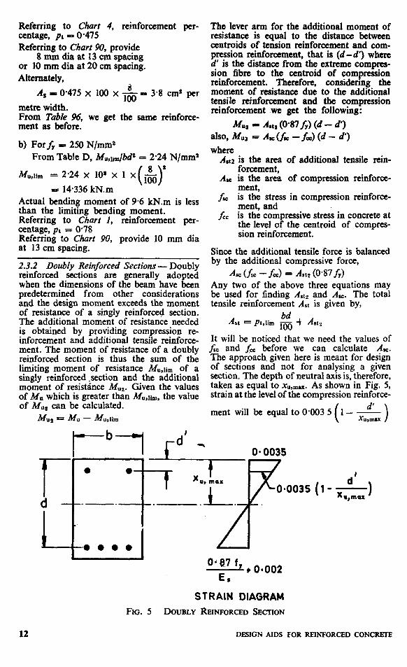
2.3.2 Doubly Reinforced Sections - Doubly reinforced sections are generally adopted when the dimensions of the beam have been predetermined from other considerations and the design moment exceeds the moment of resistance of a singly reinforced section. The additional moment of resistance needed is obtained by providing compression re- inforcement and additional tensile reinforce- ment. The moment of resistance of a doubly reinforced section is thus the sum of the limiting moment of resistance Mu,lim of a singly reinforced .section and the additional moment of resistance Mu,. Given the values of Mu which is greater than M”,lim, the value of Mu, can be calculated.
Mu, = Mu - Muslim
The lever arm for the additional moment of resistance is equal to the distance between centroids of tension reinforcement and com- pression reinforcement, that is (d-d’) where d’ is the distance from the extreme compres- sion fibre to the centroid of compression reinforcement. Therefore, considering the moment of resistance due to the additional tensile reinforcement and the compression reinforcement we get the following:
Mu, - Asts (0*87f,) (d - a,) also, Mu, =&Us-fQC)(d-J’) where
A1t2 is the area of additional tensile rein- forcement,
AK is the area of compression reinforce- ment,
I= is the stress in compression reinforce- ment, and
fee is the compressive stress in concrete at the level of the centroid of compres- sion reinforcement.
Since the additional tensile force is balanced by the additional compressive force,
A, (l;c - fee) = At, (0*87&j Any two of the above three equations may be used for finding Alt, and A,. The total tensile reinforcement Ast is given by,
Ast = Pblim m bd $ Asc,
It will be noticed that we need the values of frc and J& before we can calculate Al. The approach, given here is meant for design of sections and not for analysing a given section. The depth of neutral axis is, therefore, taken as equal to x,,,-. As shown in Fig. 5, strain at the level of the compression reinforce-
ment will be equal to O-003 5 (
d’ 1- -
XU,UWZ >
12
STRAIN OlAGRkM FIG. 5 DOUBLY REINKIRCED SECI-ION
DESIGN AIDS FOR REINFORCED CONCRIXE
For values of d’/d up to 0.2, fee is equal to 0446 fck; and for mild steel reinforcement fz would be equal to the design yield stress of 0.87 fY. When the reinforcement is cold- worked bars, the design stress in compression reinforcement fw for different values of d’/d up to 0.2 will be as given in Table F.
TABLE F STRESS IN COMPRESSION REINFORCEMENT ftc, N/mm* IN DOUBLY
REINFORCED BEAMS WITH COLD- WORKED BARS
(Clause 2.3 2)
f Y9
N/mm’
415
500
d’ld
-A , 0.0s 0.10 O-15 0.20
355 353 342 329
424 412 395 370
2.3.2.2 Astz has been plotted against (d -d’) for different values of MU, in Charts 19 and 20. These charts have been prepared for fs = 217.5 N/mm2 and it is directly appli- cable. for mild steel reinforcement with yield stress of 250 N/mm*. Values of Aat? for other grades of steel and also the values of A, can be obtained by multiplying the value read from the chart by the factors given in Table G. The multiplying factors for A=, given in this Table, are based on a value of fee corres- ponding to concrete grade M20, but it can be used for all grades of concrete with little error.
TABLE G MULTIPLYING FACTORS FOR USE WITH CHARTS 19 AND 20
‘Clause 2.3.2.1)
f N&P
FACTOR FACTOR FOR A, FOR d’jd FOR
A c--
at* 0.05 0.10 0.15 0.2
250 1.00 1.04 1.04 1.04 1.04
415 0.60 0.63 0.63 0.65 0.68
500 0.50 0.52 0.54 0.56 0.60
2.3.2.2 The expression for the moment of resistance of a doubly reinforced section may also be written in the following manner:
Mu = Mu,lim + %(0*87fy) (d-d’)
Mu Mu,lim
bj2 = bd” ___ + -&(0*87f,)( I- ;>
where ptz is the additional percentage of tensile reinforcement.
Pt = phlim + pt2
PC =P”[-L-]
The values of pt and pc for four values of d’jd up to 0.2 have been tabulated against MU/bd2 in Tables 45 to 56. Tables are given for three grades of steel and four grades of concrete.
Example 3 Doubly Reinforced Beam
Determine the main reinforcements re- quired for a rectangular beam section with the following data:
Size of beam 30 x 6Ocm Concrete mix M 15 Characteristic strength of 415 N/mm2
reinforcement Factored moment 320 kN.m
Assuming 25 mm dia bars with 25 mm clear cover,
d = fj0 - 2.5 - 225 = 56*25 cm
From Table D, for fy = 415 N/mm2 and f ck = 15 N/mm2
Mu,linJbd”=2.07 N/mm2 = 2.07 x IO2 kN/m” .*. Mu,lim -2.07 x 10³ bd2
30 56.25 56.25 -2.07 x 10” x loo x Ts- x -100-
= 196.5 kN.m Actual moment of 320 kN.m is greater than Mu,lim * . . The section is to be designed as a doubly
reinforced section.
Reinforcement from Tables
Mu 320 $$ = O-562 5)2 x 10³~~~~~ N/mm2
d’/d c 2.5 + 1.25 i o,07 5625 >
Next higher value of d’/d = 0.1 will be used for referring to Tables.
Referring to Table 49 corresponding to
MU/bd2 = 3.37 and $ = 0.1,
Pt = 1.117, pc = 0.418 . . . At - 18.85 cm2, A, = 7.05 cm2
REINFORCEMENT FROM CHARTS
(d-d’) = (56.25 - 3.75) - 52.5 cm Mu2 - (320 - 196.5) = 123.5 kN.m
Chart is given only for fy = 250 N/mm2; therefore use Chart 20 and modification factors according to Table G. Referring to Chart 20,
Art2 (for fY = 250 N/mm2) = 10.7 cm2
FLEXURAL MEMBERS 13
usia Jl¶odibrion factors given in for B Y = 415 N/nuns,
I& - 10.7 x 0.60 r! 6-42 cm* ,& I 10.7 x 0.63 = 674cm’
Referring to ruble E,
Table G
pt,nm - 072
* Ast,u,n -0.72 .x 5625 x 30
. . ,oo - 1215cm’
A*: E 12.15 + 642 = 18.57 cm’ These values of At and AE are comparable to the values obtained from the table.
2.4 T-SECTIONS
The moment of resistance of a T-beam can be considered as the sum of the moment of resistance of the concrete in the web of width b, and the contribution due to ,flanges of width br.
The maximum moment of resistance is ob- tained when the depth of neutral axis is x,,,~. When the thickness of flange is small, that is, less than about 0.2 d, the stress in the flange will be uniform or nearly uniform (see Fig. 6) and the centroid of the compres- sive force in the flange can be taken at Df/2 from the extreme compression fibre. There- fore, the following expression is obtained for the limiting moment of resistance of T-beams with small values of Dfjd.
x(br-bw)h( d-$)
where Mll,llltniiveb 30.36 fd bwxu,,,,.x (d-O.416 x0,,,,&. The equation given in E-2.2 of the code is the same as above, with the numericals rounded off to two decimals. When the flange thick-, ness is greater than about 0.2 d, the above expression is not corre4zt because the stress
distribution in the flanp would not be uni- form. The expression Bven in E-22.1 of the Code is an approximation which makes allo- wance for the variation of stress in the flange. This expression is obtained by substitutin# JY for &in the equation of E-2.2 of the CO& yf being equal to (0.15 X,,m& + 065 or) but not greater than Dr. With this m&&a- tion,
M udin~~T 9 Mu,lirn,web f 0446 f&
Mr-WY+ - f )
Dividing both sides by&k bw P,
x(& l)$(l+$)
where xu;= + 0.65 !$
but .f < $
Using the above expression, the ~2: of the moment of resistance M u,lim,T~ck b,# for different values of h/b* and &/d have been worked out and given in Tables 57 to 59 for three grades of steel.
2.5 CONTROL OF DEFLECTION
2.5.2 The deffection of beams and slabs would generally be, within permissible limits if the ratio of span to effective depth of the member does not exceed the values obtained in accordance with 22.2.1 of the Code. The following basic values of span to effective depth are given:
En\!;;;Eorted
Cantilever
20
“4
0.0. 047 f” -* 0.002
0.87 f, -_b E,
STRAIN DIAGRAM STRESS DIAORAM
ho. 6 T-SECTION
14 DBSIGN AIDS FOR REINPORCED CDNCRETE

Further modifying factors are given in order to account for the effects of grade and percentage of tension reinforcement and percentage of compression reinforcement.
2.5.2 In normal designs where the reinforce- ment provided is equal to that required from strength considerations, the basic values of span to effective depth can be multiplied by the appropriate values of the modifying factors and given in a form suitable for direct reference. Such charts have been prepared as explained below :
4
b)
The basic span to effective depth ratio for simply supported members is multi- plied by the modifying factor for ten- sion reinforcement (Fig. 3 of the Code) and plotted as the base curve in the chart. A separate chart is drawn for each grade of steel. In the chart, span to effective depth ratio is plotted on the vertical axis and the tensile reinforcement percentage is dotted on the horizontal axis. When the tensile reinforcement ex- .ceeds ~I,II,,, the section will be doubly reinforced. The percentage of compres- sion reinforcement is proportional to the additional tensile reinforcement @t - PM,,) as explained in 2.3.2. However, the value of Pt,lim and pc will depend on the grade of concrete also. Therefore, the values of span to effective depth ratio according to base curve is modified as follows for each grade of concrete: 1)
2)
3)
For values of pt greater than the appropriate value of pt,lim, the value of (pt - pt,lim) is cal- culated and then the percentage of compression reinforcement p= re- quired is calculated. Thus, the value of pc corresponding to a value of pt is obtained. (For this purpose d’/d has been assumed as 0.10 but the chart, thus obtained can gene- rally be used for all values of d’/d in the normal range, without signi- ficant error in the value of maximum span to effective depth ratio.) The value of span to effective depth ratio of the base curve is multiplied by the modifying factor for com- pression reinforcement from Fig. 4 of the Code. The value obtained above is plotted on the same Chart in which the base curve was drawn earlier. Hence the span to effective depth ratio for doubly reinforced section is plotted against the tensile reinforcement percentage pt without specifically indicating the value of pc on the Chart.
25.3 The values read from these Charts are directly applicable for simply supported members of rectangular cross section for spans up to 10 m. For simply supported or continuous spans larger than 10 m, the values should be further multiplied by the factor (lo/span in me&es). For continuous spans or cantilevers, the values read from the charts are to be modified in proportion to the basic values of span to effective depth ratio. The tn.l~G$ing factors for this purpose are as
. .
conned; spans &
In the case of cantilevers which are longer than 10 m the Code recommends that the deflections should be calculated in order to ensure that they do. not exceed permissible limits.
2.54 For flanged beams, the Code recom- mends that the values of span to effective depth ratios may be determined as for rectan- Eoeons, subject to the followmg modi-
. . 4
b)
The reinforcement percentage should be,bcz&zm the area brd while referrmg
The value of span to effective depth ratio obtained as explained earlier should be reduced by multiplying by the following factors:
b&v Factor
>:::3 For intermediate values, linear interpola-
tion may be done.
Nom --The above method for flanged beams alay sometimes give anomalous mwlts. If the fhges arc ignored and the beam is considered as a rectangular section, the value of span to effective depth ratio thus obtained (percen
Y of rciaforcemcnt being based
on the area l&) s ould always be oa the safe side.
2.5.5 In the case of tw way slabs supported on all four sides, the s P orter span should be considered for the purpose of calculating the span to effective depth ratio (see Note 1 below 23.2 of the Code).
2.5.6 In the case of flat slabs the longer span should be considered (30.2.2 of the Code). When drop panels conforming to 30.2.2 of the Code are not provided, the values of span to effective depth ratio obtained from the Charts should be multiplied by 0.9.
Example 4 Control of Deflection
Check whether the depth of the member in the following cases is adequate for control- ling deflection :
a) Beam of Example 1, as a simply suppor- ted beam over a span of 7.5 m
FLBXURAL MEMBERS 15
b)
Cl
a>
Beam of Example 3, as a cantilever beam over a span of 4.0 m Slab .of Example 2, as a continuous slab spanning in two directions the shorter and longer spans being, 2.5 m and 3.5 m respectively. The moment given in Example 2 corresponds to shorter spa’n.
Actual ratio of Span Eflective depth
= (56.;5;,oo) = 13.33
Percentage of tension reinforcement required,
pt = 0.6
Referring to Char1 22, value of Max Span
( > T
corresponding to Pt = 0.6, is 22.2.
Actual ratio of span to effective depth is less than the allowable value. Hence the depth provided is adequate for controlling deflec- tion.
b) Actual ratio of Span Etfective depth
‘(d&J = 7.11
Percentage of tensile reinforcement, pr = 1.117 Referring to Churl 22,
Max value of %!a? = 21.0 ( 1 Cl
For cantilevers, values read from the Chart are to be multiplied by 0.35.
:. Max value of 1 I/d for ) =21.0x0*35=7.35 cantilever J
* The section is satisfactory for control . . of deflection.
c) Actual ratio of Span Effective depth
2.5 =-= 31.25 0.08
(for slabs spanning in two directions, the shorter of the two is to be con- sidered) (i) Forfv = 415 N/mm2
pt = 0,475 Referring to Chart 22,
Max Span = 23.6 (-> d
For continuous slabs the factor obtained from the Chart should be multiplied by 1.3.
:. Max “7 for continuous slab
= 23.6 x 1.3 F 30.68 Actual ratio of span to effective depth is
slightly greater than the allowable. Therefore the section may be slightly modified or actual deflection calculations may be made to as- certain whether it is within permissible limits.
(ii) F0r.j; = 250 N/mm2 pt = 0.78
Referring to Chart 21,
Max Span = 31.3 (-1 d
:. For continuous slab,
Max %% = 31.3 x 1.3 d
= 40.69
Actual ratio of span to effective depth is less than the allowable value. Hence the section provided is adequate for controlling deflection.
16 DESIGN AIDS FOR REINFORCED CONCRETE

As in the Original Standard, this Page is Intentionally Left Blank


As in the Original Standard, this Page is Intentionally Left Blank


As in the Original Standard, this Page is Intentionally Left Blank


As in the Original Standard, this Page is Intentionally Left Blank


As in the Original Standard, this Page is Intentionally Left Blank


As in the Original Standard, this Page is Intentionally Left Blank


As in the Original Standard, this Page is Intentionally Left Blank

TABLE 1 FLEXURE - REINFORCEMENT PERCENTAGE, pc FOR SINGLY REINFORCED SECTIONS
N/mm= b
E 040 O-45 O-50
1.10 l-12 l-14 l-16 l-18
1.20 1.22
::z l-28
1.30 l-32 1.34
I::
0.141 Oa5 0.074 O-166 @lOO OQ86
8’E . 8’::; . o&E Q240 O-144 O-125
O-276 O-302 O-329 O-356 O-383
O-265 0.290
E O-368
0.159 0.175
i-E Oh
0.138 0.151 0.164 O-178 0’191
0.410 O-421 0.433
IZ
O-394 O-237 Q-205 O-405 0.244 0.211 O-415 O-250 O-216 O-426 O-257 o-222 O-437 0’263 O-227
8::;; 0489 O-500 O-512
0448 O-270 O-458 0.276 0469 0283 0.480 O-289 0.491 0.2%
0.523 O-535 0.546 0.558 O-570
O-502 0.513 0.524
8:::;
0.303
EJ O-323 O-329
0.262 o-267 O-273 O-279 O-285
O-581 0393 @605
8’:;; .
0.558 0370 0.581 0.592 O-604
Ei O-350 O-357 O-364
O-291 O-297 O-303 O-309 O-315
0.641 O-615 0.371 0.321 0.653 0.627 0.378 0.327 O-665 O-639 0.385 0.333 O-678 O-650 0.392 O-339 O-690 O-662 O-399 O-345
8E I:G O-727 O-698 O-740 O-710 0.752 O-722
0.765 O-778
x:z 0.816
O-734 o-747 0.759 0.771 O-784
0442
X:t:Y O-465 0.472
O-382 O-389 0.395
x:z
250 415 480
0993 l-007 1*021 1935 l-049
l-136 l-151 l-166 1.181 l-197
l-212 1228 1,243 1.259 1.275
i’ . O-503 O-510
O-398
i;:
0.423
O-518 O-526
8:Z 0’550
O-448 0.455 O-461 0468 O-475
O-430 O-436 O-443
8:::
0.558 0482 o-463 O-566 0489 O-469 0’574 0.496 O-476 O-582 0’503 0483 O-590 o-510 0.490
O-517 0.525 O-532 0.539 0.546
O-497
o”:?i 0.518 0.525
0554 0.561 0.569 O-576 O-584
O-532 0.539
0.685 O-693 O-703 0.712
O-592
fY
240 250 415 480 500 : 7 ck
25
NOTE -Blanks indicate inadmissible reinforcement percentage (see Table E).
FLeXURAL MEMBERS
240 250 415 480
f ck
20
--
TABLE 2 FLEXURE -REINFORCEMENT PERCENTAGE, pt FOR SINGLY REINFORCED ‘SECTIONS
l-05 0.538 1.10 O-566 1’15
OO’E :‘z * . O-650
E O-678 O-707
E 0.736 O-765
l-50 0.795
1.55 O-825
;:g 8$;: . l-70 O-916 l-75 0947
l-80 %! I-85 *
E 1’041 1.073
200 lm6
3g l-119
E :::z l-159
210 l-172
f’:: l-185
. 1*199
f’:; . :‘E . 220 l-239
“0% O-188 O-213 O-237
0.517 O-543 0.570 0.597 @624
O-651 O-679 0.707 0.735 0’763
O-073
Efl 0.111 0’123
izi! FEJ . O-131 O-143
XE O-181
O-201
::E 0.242 0.255
O-193
Ffg
O-245
::a:; O-297 O-311 0’325
0.258
8:;:; 0.298 0312
0.339 O-354
EL! . 0397
X:E ;:gj O-521 0.500 o-537 O-515 0.553 o-531
0.537 0’543 O-550 O-556 O-562
f& - zO.N/m'
1.253
:‘26: 1%
LOZ
l-323
E
:‘:z .
:‘z . l-423 l-438 l-452
l-203 l-216
:z 1.256
l-338 l-352 1966 1380 1’394
1467 1~482 l-497
:::;;
1.542 1481 l-558 1’495
::z :::1’: l-604 l-540
1.782
:‘E . l-833
1.632 l-647 l-663 _g;; .
l-711
:‘% . l-760
O-627 O-633
I::
0.661
pj .
O-690
o-697 0.704 o-711 o-719 O-726
O-734 O-741 O-748 0.756 0.764
x’% . O-615 0.621 0.628
O-635
xzz 0.655 0.662
Num -Blanks lndk$te inadmissible reinforcement pcmntagc (see Table J%
48 DESIGN AIDS FOR REINFORCED CGNCRRI’E

TABLE 3 FLEXURE - REINFORCEMENT PERCENTAGE, pt FOR SINGLY REINFORCED SECTIONs
/ck = 25 N/mms
0.30 0.35
g
0.146 O-171 O-195
:z
O-271 O-296 0?321 O-347 O-373
0.80 O-85
8C lfl0
0.399 t-I.425 0.451 O-477 O-504
l-05 1.10 1.15
::z
O-530
8% O-611 O-638
l-30 l-35
:z 1.50
0.666 0.693 0.721 0.749 O-777
1.80 0.949 l-83 0979 1.90 l-009 1.95 l-038 2-00 1,068
2-05 210 2.15
$12”:
:z l-160 l-191 1.222
l-254 13283 l-317 l-350 l-382
250 415 480 500.
0.140 0.084 0.164 O-099 0188 0.113 O-211 Of27 0.236 O-142
O-070
:%z O-106 O-118
O-260
!% 0.333 O-358
O-156 0.171 0.186 O-201 O-216
0.130 0.142 O-154 0167 0.179
0231
X% 0.276 O-291
0191 O-204 0.216 0229 O-242
0.509 6535 O-561
z-;;: .
0.307 O-322 0.338 0353 0.369
0.255 0.267 0.280 0.293 0.306
0.639
X:% @719 0.746
o-773
8::: 0.856 O-883
O-385 O-401 w417 0.433 O-449
0.333 0.347
8% O-388
0.320 O-333 0.346 O-359 0373
O-466 O-482 0.499 0.515 O-532
0403
x::::
8:%
O-387
x%Y 0.428 O-442
O-911 O-940 0968
YZ .
O-549 O-566 O-583 O-601 O-618
O-415 O-489
fj:$
0.456 0.470 0.484 O-498 o-513
1.055
: :% l-143 1.173
O-635 O-653 0.671 0.689 O-707
8% O-580 0.596 0.611
O-527 0542 O-557 O-572 0.587
l-204 l-234 l-265
: :%
0.725 O-743 0.762 0781 o-799
O-627 O-643
ZR O-691
O-602 0.617 O-632 0.648 0.663
Mlw2, fu, N/mm2 N/mms 7’
L --Y
250 415 500
1.415 1.358 1448 l-390 1482 l-422 1.515 l-455 l-549 1487
% 290 2-95 3.00
l-584 1.618 1.653 l-689 l-724
3.05 3.10 3.15
::::
l-760 1.797 1.834 l-871 1909
33%
:::t 3-38
1.947 l-869 l-962 l-884 l-978 l-899 1993 l-914 2QO9 l-929
2.025 l-944
Z:% :‘zc . 2.072 l-989 2-088 2.005
2.104 2.120
z::: 2.170
3.60 3.62
::z 3.68
2.186 2.203 2.219
;:22:;
3.70 2.270 3-72 2.287 3.74 2.304
NOTE - Blanks indicate inadmissible reinforcement percentage (see Table E).
l-520
:::z l-621 l-655
::% l-760 l-796 1.832
2.099 2.115 2.131 2.147 2.163
2.179 2196
O-818 0.837
::::z O-896
::;:z O-956 o-977 0.997
1.018 1.039 l-061 l-082 1.104
::::;
:::z 1.162
O-679
:z: O-727 O-744
8% O-794 O-811 0.828
0.845 O-863 0.880 0.898 O-916
0.935 0942
fY
240 250 4'1 5 480 500 7 ck
25
m3xuRAL MEMBERS 49
'Y
240 250 415 480 500 f ck
30
TABLE 4 FLEXURE - REINFORCEMENT PERCENTAGE, pi FOR SINGLY REINFORCED SECTIONS
0.140
8’::; . @211 0235
0380 0405 0.429 0.454 0.479
0.525 0552 0.578
x’z .
~~i?i 0.712 0739 0.766
@631
x::: 0.709 0’735
8’;1;: oi49
x:zi
0.762 0.788
xz:: 0.868
0.932 0.895 0961 0.922 0.989 0.950 1.018 0977 1946 1.005
1.075
:x . 1.163 1.192
1’173
::i!f 1.260 1289
250 500
MUW, A. N/mm2
N/mm2 r240 * -7
250 415 480 500
0.070 0.082 0.093 0.105 0.117
255 1.374 1.319
fZ ::zi ::zi 270 1467 1.408 275 1.498 1.438
c8”:
tz 3.00
3.05 3.10 3.15
33:g
0.252 0.265 Ct.277 0.290 0.303
3.30 1.859 3.35 1.893
:z zi 3.50 1998
0316
xz 0.355 0.368
3.55 3.60 3.65 3.70 3.75
@381 3.80 0.394 3.85
x:z it:z 0.434 4.00
oo:z 0.475 0488 0502
fd = 30 N/mm2
1.530 1.562 1.594 1.626 1.659
~~~ 1.530 1.561 1.592
1.691 1.624 1.725 1.656 1.758 1.687 1.791 1.720 1.825 1.752
1.785 1.075 0.930 1.818 1.095 0.947 1.851 1.115 0.964 I.884 1.135 0.981 1.918 1.156 0.999
2z 2105 2.142 2.178
1.952 l-176 1.986 1.197 2021 1.218 2056 1.239 2091 1.260
2215 2253 2291 2329 2367
f:iz i::z 2485 2386 2.525 2.424 2566 2463
NOTE - Blanks indicate inadmissible reinforcement pyceniage (see Table E).
0.794 @687 0.812 0.702 0.830 0.718 0.848 0.733 0.866 0.749
is; 0.797 0813 0.829
0.978
zz3 1.036 1.055
0.846 0.812 0.862 0.828 0.879 0.844 0.896 0.860 0.913 0.876
KG; 1.053 1.071 1.089
1.281 1.303 1.325 1.347 1.369
1.108
:‘:z . 1.164 1.184
1.391 1.414
0.734 0.750 0.765 0.781 0.796
0976
zf : 1.028 1.046
KS 1.099 1.118
so DESIGN AIDS FOR REmFORCJiD CONCREIB


As in the Original Standard, this Page is Intentionally Left Blank


As in the Original Standard, this Page is Intentionally Left Blank

3. COMPRESSION MEMBERS
3.1 A$MU\;,OADED COMPRESSION lower sectioqs would eliminate tho need for any calculation. This is particularly useful
All compression members arc to be designed as an aid for deciding the sizes of columns at the preliminary design stage of multi-
for a minimum eccentricity of load in two oribcioal directions. Clause 24.4 of the Code
sforeyed buildings. I
specifiks the following minimum eccentri- city, emin for the design of columns: Example 5 Axially Loaded Column
1 i-D subject to a minimum of emin=ggg 3o
Determine the cross section and the reinforcement required for an axially loaded
2 cm. columc with the following data: where
Factored load Concrete grade Characteristic strength of
reinforcement
3000kN M20 415 N/mm’
1 is the unsupported length of the column (see 24.1.3 of the Code for definition of unsupported length), and
D is the lateral dimension of the column in the direction under consideration.
Unyoyior;d length of 3.0 m
After determining the eccentricity, the section should be designed for combined axial load and bending (see 3.2). However, as a simplifi- cation, when the value of the mininium eccentricity calculated as above is less than or equal to 0*05D, 38.3 of the Code permits the design of short axially loaded compression members by the following equation:
P,=@4f,k AC-i-0.67 fY Ar
The cross-sectional dimensions required will depend on the percentage of reinforcement. Assuming 1.0 percent reinforcement and referring to Chart 25,
Required cross-sectional area of column, A, - 2 700 cm*
Provide a section of 60 x 45 cm.
Area of reinforcement, A, - 1.0 x m~$,j2
where 1: 27 cm8
PU is the axial load (ultimate), A, is the area of concrete, and Asc is the afea of reinforcement.
The above equation can be written as
We have to check whether the minimum eccentricity to be considered is within 0.05 times the lateral dimensions of the column. In the direction of longer dimension,
I D &in - --
500 +30 P” = 0.4 f& PA, A, - +$) t- 0.67fy loo
where
As is the gross area of cross section, and p is the percentage of reinforcement.
Dividing both sides by A,, PU = @4&( 1 - j&) +“‘67fy $j
Charts 24 to 26 can be used for designing short columns in accordance with the above equations. In the lower section of these charts, P./A, has been plotted against reinforcement percentage p for different grades of concrete. If the cross section of the column is known, PU/Al can be calculated and the reinforcement percentage read from the chart. In the upper section of the charts, PU/As is plotted against PU for various values of AS. The combined use of the upper and
3*0x 102 60 = 500
+ jg P 0.6 j-2.0 - 2.6 cm
or, e&D = 26160 = O-043
In the direction of the shorter dimension, 3.0 x 10² emrn = 500 + 45
30 = 0.6 + 1.5
= 2.1 cm or, e,i,/b = 2*1/45 = @047
The minimum eccentricity ratio is less than @05 in both directions. Hence the design of the section by the simplified method of 38.3 of the Code is valid.
3.2 COMBINED AXIAL LOAD AND UNIAXIAL BENDING
As already mentioned in 3.1, all com- pression members should be designed for
COMPRESSION MEMBERS 99
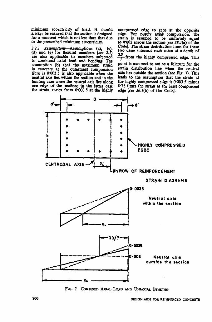
minimum eccentricity of load. It shouldalwaysbe ensuredthat the scotionis designedfor a moment whichis not lessthan that dueto the prescribedtinimum eccentricity.
3.2.1 Amanptio&Assumptiom (a), (c),(d) and (e) for flexural members (see 2.1)are also applicable to members subjcotedto combined axial load and bending. ‘Theassumption (b) that the maximum strainin concrete at the outermost eom ression
ifibre is 04N35 is also applicablew en theneutralaxis k withinthe seotionand in thelimitingcase when the neutralaxis lies alongone edge of the section; in the latter oascthe strain varies from 0@035 at the highly
compressed edge to zero at the opposiked~. For purely axial compression,thestrain is assumed to be uniformly equal00002 acxossthe seotion[see 38.l(a) of theCode]. The strairidistributionlines for these~’ oases intersecteaeh other at a depth of
~ffom the highly compressed edge. This
point is assumedto act as a fulcrum for thestrain distribution line when the neutralaxis lies outsidethe motion(see Fig. 7). Thisleads to the assumption that the strain atthe highly compresseded~ is 00035 minus0?5 times the strainat the leastcompressededge [see 38.Z(b) of the Cole],
“-i t- - ---1-”
I: 1
● ‘* ●
I
●*
●
● i●
●c
b●:
00
I I
!* ●t
● J: IHIWilmY● 00 EOOE
C6MPRE S SE II
CENTRO13AL AXIS
+’+ ikh ROW OF REINFORCEMENT
STRAIN DIAGRAMS
0035
Neutral axiswlthln the scctlon
-30/7-1
-— ----- Neutral axisoutside the sect ion
FIG. 7 Cmramm Am- LOAD AND UNIAXIAL BENDING
No DESIGNAIDSIK)RREINFORCEDCONCR81E

3.2.2 Stress Block Parameters Wh&n the Area of stress block Neutral Ax& Lies O&side the Section - When the neutral axis lies outside the section, g 4 the shape of the stress block will be as. indi-
- 0446f,D-5 ( >
,-D
cated in Fig. 8. The stress is uniformly 0446fd for a distance of Ly from the highly
= 04461&D +gD
compressed edge because the strain is more - 0446fdr D than 0402 and thereafter the stress diagram [l-&&J] is parabolic.
The centroid of the stress block will be found by taking moments about the highly compressed edge.
Moment about the highly compressed edge D pO1446fckD i ( 1 -$ gD
t i
The position of the centroid is obtained by dividing the moment by the area. For diier- ent values of k, the area of stress block and
STRAIN DIAORAM the position of its centroid are given in Table H.
O-446 1,
BTRESS OIAORAW
FIG. 8 STRBSS BLOCK WHEN THE NEUTRAL Am h¶ oUT?3IDE THE SECTION
Let x0- kD and let g be the ditference between the strxs at the highly compressed edgo and the stress at the least compressed edge. Considering the geometric properties of a parabola,
-o+Mf& & ( 1
1
TABLE H STRESS BLOCK PARAhUTTERS WHEN THE NETmmtA&mA?N LIES OUTSIDE
(Clause 3.2.2)
Nom-Values of stress block parameters have been tabulated for values of k up to 4’00 for infom- tion only. For construction of interaction d@cams it b merally adaquata to consider values of k up to about 1.2.
33.3 Construction of Interaction Diagram - Design charts for combined axial compression and bending are given in the form of inter- action diagmms in which curyes for PJbDfd versus MdbD* fb are plotted for different values of p/f&, where p is the reinforcement percentage.
COMPRESSlON MEMBERS 101
3.2.3.2 For the case of purely axial com- pression, the points plotted on the y-axis of the charts are obtained as follows:
P,= 0446f,rbd + ‘g (A - 0.446 fek)
where
fr is the compressive stress in steel corres- ponding to a strain of 0.002.
The second term within parenthesis repre- sents the deduction for the concrete replaced by the reinforcement bars. This term is usually neglected for convenience. However, a9 a better approximation, a constant value corresponding to concrete grade M20 has been used in the present work so that the error is negligibly small over ;he range of concrete mixes normally used. An accurate consideration of this term will necessitate the preparation of separate Charts for each grade of concrete, which is not considered worthwhile.
3.2.3.2 When bending moments are also acting in addition to axial load, the points for plotting the Charts are obtained by assuming different positions of neutral axis. For each position of neutral axis, the strain distribution across the section and the stress block parameters are determined as explained earlier. The stresses in the rein- forcement are also calculated from the known strains. Thereafter the resultant axial force and the moment about the centroid of the section are calculated as follows:
a) When the neutral axis lies outside the section
li
where
Cl -
Pi -
i-1
coefficient for the block to be taken (see 3.2.2);
area of stress from Table H
Ad bx
where A,i is the area of rein-
forcement in the ith row;
fii - stress in the ith row of reinform
fci - n -
102
ment, compression being positive and tension being negative; stress in concrete at the level of the ith row of reinforcement; and number of rows of reinforcement.
The above expression can be written as n
Taking moment of the forces about the centroid of the section,
+ x g (.Ai - fci).Yi
where
i- 1
C,D is the distance of the centroid of the concrete stress block, measured from the highly compressed edge; and
Yi is the distance from the centroid of the section to the ith row of reinforce- ment; positive towards the highly compressed edge and negative to- wards the least compressed edge.
Dividing both sides of the equation by fck bD”,
c, (O-5-Cd
n
+X*(&i -&i)(s)
i- 1
b) When the neutral axis lies within the section
In this case, the stress block parameters are simpler and they can be directly incorpora- ted into the expressions which are otherwise same as for the earlier case. Thus we get the following r;xpressions:
=@36k+ c &j&&d i-1
n
where
k- Depth of neutral axis D
DESIGN AIDS FOR REINFORCED CONCRETE

An approximation is made for the value Offci for M20, as in the case of 3.2.3.1. For circular sections the procedure is same as above, except that the stress block para- meters given earlier are not applicable; hence the section is divided into strips and summation is done for determining the forces and moments due to the stresses in concrete.
3.2.3.3 Chartsfor compression with bending - Charts for rectangular sections have been given for reinforcement on two sides (Charts 27 to 38) and for reinforcement on four sides (Charts 39 to 50). The Charts for the latter case have been prepared for a section with 20 bars equally distributed on all sides, but they can be used without significant. error for any other number of bars (greater than 8) provided the bars are distributed equally on the four sides. The Charts for circular section (Charts 51 to 62) have been prepared for a section with 8 bars, but they can generally be used for sections with any number of bars but not less than 6. Charts have been given for three grades of steel and four values of d’/D for each case men- tioned above.
The dotted lines in these charts indicate the stress in the bars nearest to the tension face of the member. The line for fs, I; 0 indicates that the neutral axis lies along the outermost row of reinforcement. For points lying above this line on the Chart, all the bars in the section will be in compression. The line for fSt = fYd indicates that the outermost tension reinforcement reaches the design yield strength. For points below this line, the outermost tension reinforcement undergoes inelastic deformation while succes- sive inner rows may reach a stress of fyd. It should be noted that all these stress values are at the failure condition corresponding to the limit state of collapse and not at work- ing Ioads.
3.2.3.4 Charts for tension with bending - These Charts are extensions of the Charts for compression with bending. Points for plotting these Charts are obtained by assum- ing low values of k in the expressions given earlier. For the case of purely axial tension,
Pu - g (O-87 fy)
hk (@87fy)
Charts 66 to 75 are given for rectangular sections with reinforcement on two sides and Charts 76 to 85 are for reinforcement on four sides. It should be noted that these charts are meant for strength calculations
only; they do not take into account crack control which may be important for tension members.
Example 6 Square Column with Uniaxial Bending
Determine the reinforcement to be provided in a. square column subjected to uniaxial bending, with the following data:
Size of column 45 x 45cm Concrete mix M 25 Characteristic strength of 415 N/mm%
reinforcement Factored load 2500kN
(characteristic load multiplied by yr)
Factored moment 200 kN.m Arraugement of
reinforcement: (a) On two sides (b) On four sides
(Assume moment due to minimum eccentri- city to be less than the actual moment).
Assuming 25 mm bars with 40 mm cover, d = 40 + 12.5 OP 52.5 mm z 5.25 cm d’/D = 5.25145 - 0.12
Charts for d’/D = 0.15 will be used
f& = 25 x 2 45 500 x x 45 103 x lo2 _ = 0.494
200 x 106 _ - 25x45~45~45~103 = 0.088
a) Reinforcement on two sides, Referring to Chart 33,
p/fck = 0.09 Percentage of reinforcement,
p = 0.09 x 25 - 2.25 As = p bD/lOO = 2.25 x 45 x 45/100
= 45.56 cm2 b) Reinforcement on four sides
from Chart 45, p&k = 0.10
p p. 0.10 x 25 = 2.5 As = 2.5 x 45 x 45/100 = 50.63 cm”
Example 7 Circular Column with Uniaxial Bending
Determine the reinforcement to be pro- vided in a circular column with the following data:
Diameter of column 50 cm Grade of concrete M20 Characteristic strength 250 N/mm2 for
of reinforcement bars up to 20 mm+
240 N/mm2 for bars over 20mm#
COMPRESSION MEMBERS 103

Factored load 16OOkN Factored moment 125 kN.m Lateral reinforcement :
(a) Hoop reinforcement (b) Helical reinforcement
(Assume moment due to minimum eccentri- city to be less than the actual moment).
Assuming 25 mm bars with 40 mm cover, d’ = 40 x 12.5 = 52.5 mm m 5.25 cm
d’/D - 5.25150 = 0.105
Charts for d’/D = 0.10 will be used.
(a) Column with hoop reinforcement
1600 x 103 20 x 50 x 50 x ioa - o’32
125 x 10 20 x 50 x 50 x 50 x 103 - 0.05
Referring to Chart 52, for fy I 250 N/mm1 p/fck = o-87
= 0.87 x 20 = 1.74 A: = pnD2/400
= 1.74 x nx50x50/400=34*16cm2
Forf, I 240 N/mm2, AS = 34.16 x 2501240 = 35.58 cm2
(b) Column with Helical Reinforcement
According to 38.4 of the Code, the $rength of a compression member with hehcal re-- inforcement is 1.05 times the strength of a similar member with lateral ties. Therefore, the, given load and moment should be divided by 1.05 before referring to the chart.
Hence,
From Chart 52, for fy = 250 N/mm2, p,$_k = 0.078
p = 0.078 x 20 = 1.56 As = 1.56 x x x 50 x 50/44X
= 30.63 cm2 For fy = 240 N/mm%, A, = 30.63 x 2501240
= 31.91 cm2
According to 38.4.1 of the Code the ratio of the volume of helical reinforcement to the volume of the core shall not be less than 0.36 (A,/Ac - 1) fck Ify where A, is the gross area of the section and Ac is the area of the core measured to the outside diameter of the helix. Assuming 8 mm dia bars for the helix,
Core_diie;; = 50-2 (4-O - 0.8)
AI/AC IP 5O’/43*6’ = 1.315 0.36 (A,,& - 1) falJlr
I egg; 0.315 x 201250
Volume of helical reinforcement Volume of core
Aarc .(42*8) 0.09 A,J, --_------=
;(43*6%) Q, a,
where, Ash is the area of the bar forming the helix and sh is the pitch of the helix. In order to satisfy the coda1 requirement,
0.09 Art&k > O*OO91
For 8 mm dia bar, Ati = O-503 cm2 sh ( 0.09 x 0.503
’ 0.0091 ‘__ < 4.97 cm
3.3 COMPRESSION MEMBERS SUB- JECT TO BIAXIAL BENDING
Exact design of members subject to axial load and biaxial bending is extremely laborious. Therefore, the Code permits the design of such members by the following equation :
lhere M,,, M,, are the moments about x and y
axes respectively due to design loads, M MUYl “Xl, are the maximum uniaxial
moment capacities with an axial load P,, bending about x and y axes res- pectively, and
ozn is an exponent whose value depends on Pu/Puz (see table below) where P uz = 0.45 fck A, + 0*75fy As:
PUIPUZ ‘an
go.2 1.0 )0*8 2.0
For intermediate values, linear interpo- lation may be done. Chart 63 can be used for evaluating Puz.
For different values of Pu/Puz, the appro- priate value of azn has been taken and curves for the. equation
(!$)“’ + (z)=” = 1.0 have been
plotted in Chart 64.
104 DESIGN AIDS FOR REINFORCED CONCRETE .
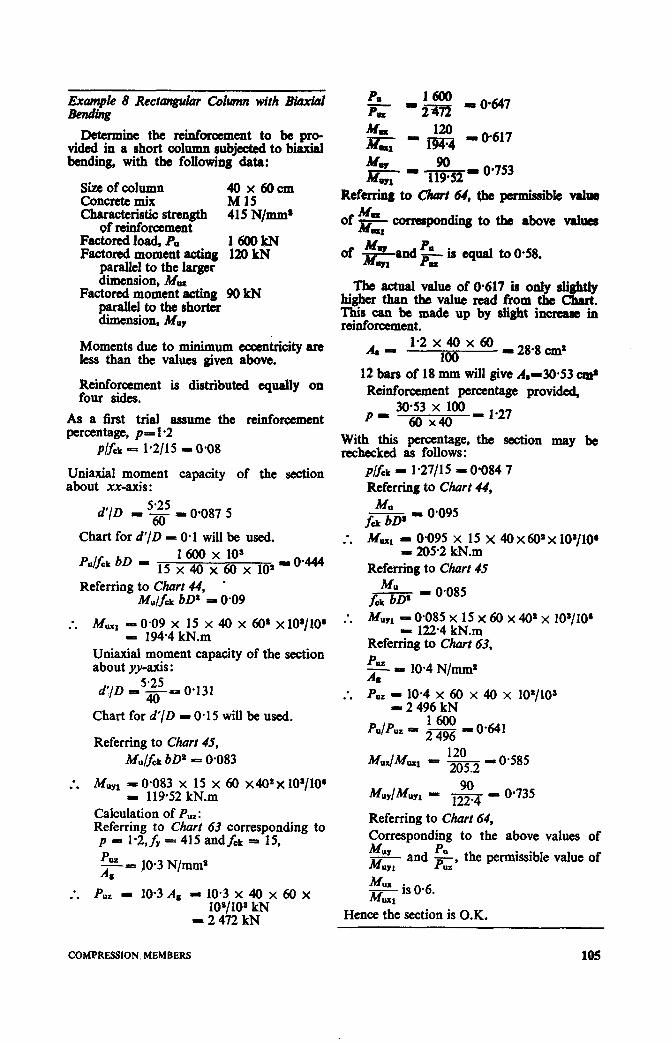
ExampIe 8 Rectangular colrmu, with Biaxial Be?tdi?lg
DeWmine the reinforcement to be pro- vided in a short column subjected to biaxial bending, with the following data:
size of column Concrete mix EPcm Characteristic strength
of reinforcement 415 N/mm’
Factored load, P,, 1600kN Factored moment acting 120 kN
parallel to the larger dimension, M,w
Factored moment acting 90 kN parallel to the shorter dimension, Mu,
Moments due to minimum eccentricity are less than the values given above.
Reinforcement is distributed equally on four sides.
As a iirst trial assume the reinforcement percentage, p= 1.2
P&k - 1*2/l 5 - 0.08
Uniaxial moment capacity of the section about xx-axis :
Referring to Churn 64, the permissible v&a MBa of ns,, qrmsponding to the above v&see
qual to 0.58.
The actual value of 0.617 is only sli&ly higher than the value read from the Chart. This can be made up by slight increase in reinforcement.
A6 - 1-2x40x60 _2&8,.&
100 12 bars of 18 mm will give A.130.53 c& Reinforcement percentage provided, p _ 30.53 x 100 6o x40 - 1.27
With this percentage, the section may be rechecked as follows:
p/f& - l-27115 = 0.084 7 Referring to Chart 44,
d’/D 5.25
- 6. - 0.087 5
Chart for d’/D = 0.1 will be used.
p&k bD = 1600 x 10s
15 x 40 x 60 x 10” - 0444
Referring to Chart 44, l
M&k bD= = 0.09
:. MUX, - 0.09 x 15 x 40 x 60’ x loylo~ - 194.4 kN.m
Uniaxial moment capacity of the section about yv_axis :
5.25 d’JD = 40- 0.131
Chart for d’/D - 0.15 will be used.
Referring to Chart 45, M&k bD’ - 0.083
:. MuYl - 0.083 x 15 x 60 x40*x 10a/lO’ I 119.52 kN.m
Calculation of P,,: Referring to Chart 63 corresponding to p = 1.2, fu = 415 and fck = 15,
10.3 x 40 x 108/10S kN 2 472 kN
60X
f$ - 0,095
Mw z 0.;9; &li x 40 x 60’ x 10*/10* . .
Referring to Chart 45
f+ - 0.085
M WI z W&354 x&52 60 x 40’ x 10a/lO’
Referring to Char; 63, PUZ Al = 10.4 N/mm2
Puz - 10.4 x 60 x 40 x lO’/lO~ - 2 496 kN
Referring to Chart 64, Corresponding to the above values of Muy PU MuY, and z’
the permissible value of
MUX - is 0.6. MUX,
Hence the section is O.K.
COMPRESSION, MEMBERS 105

3.4 SLENDER COMPRESSION MEMBERS
&?. When the slenderness ratio D or # of
a compression member exceeds 12, it is considered to be a slender compression member (see 24.2.2 of the Code); In and i, being the effective lengths with respect to the major axis and minor axis respectively. When a compression member is slender with respect to the major axis, an additional moment Mu given by the following equation (modified as indicated later) should be taken into account in the design (see 38.7.1 of the Code) :
Similarly, if the column is slender about the minor axis an additional moment M.,, should be considered.
M = Pub &” ay ( 1 2000 b
The expressions for the additional moments can be written in the form of eccentricities of load, as follows:
Mu - P, eu
where
Table 1 gives the values b or 3 for
different values of slenderness ratio.
TABLE I ADDITIONAL ECCENTRICITY FOR SLENDER COMPRESSION MEMBERS
(Chuxe 3.4)
In accordance with 38.7.1.1 of the Code, the additional moments may be reduced by the multiplying factor k given below:
where
P,, = 0.45 &k Ac + 0.75 fy A, which may be obtained from Chart 63, and Pb is the axial load corresponding to the condition of maximum compressive strain of 0.003 5 in concrete and tensile strain of O%Ml2 in outermost layer of tension steel.
Though this modification is optional ac- cording to the Code, it should always be taken advantage of, since the value of k could be substantially less than unity.
The value of Pb will depend on arrangement of reinforcement and the cover ratio d’/D, in addition to the grades of concrete and steel. The values of the coefficients required for evaluating Pb for various cases are given in Table 60. The values given in Table 60 are based on the same assumptions as for members with axial load and uniaxial bending.
The expression for k can be written as follows :
Chart 65 can be used for finding the ratio of k after calculating the ratios P,/Pu, and pb/&z.
Example 9 Slender Column (with biaxial bending)
Determine the reinforcement required for a column which is restrained against sway, with the following data:
Size of column 40 x 30 cm Concrete grade M 30 Characteristic strength 415 N/mm1
of reinforcement Effective length for 6-O m
bending parallel to larger dimension, Z,
Effective length for 5.0 m bending parallel to shorter dimension, ly
Unsupported length 70m Factored load 1500kN Factored.moment in the 40 kN.m at top
d!““;f larger and 22.5 kN.m at bottom
DESIGN AIDS FOR RRINFORCED CONCRKI-E
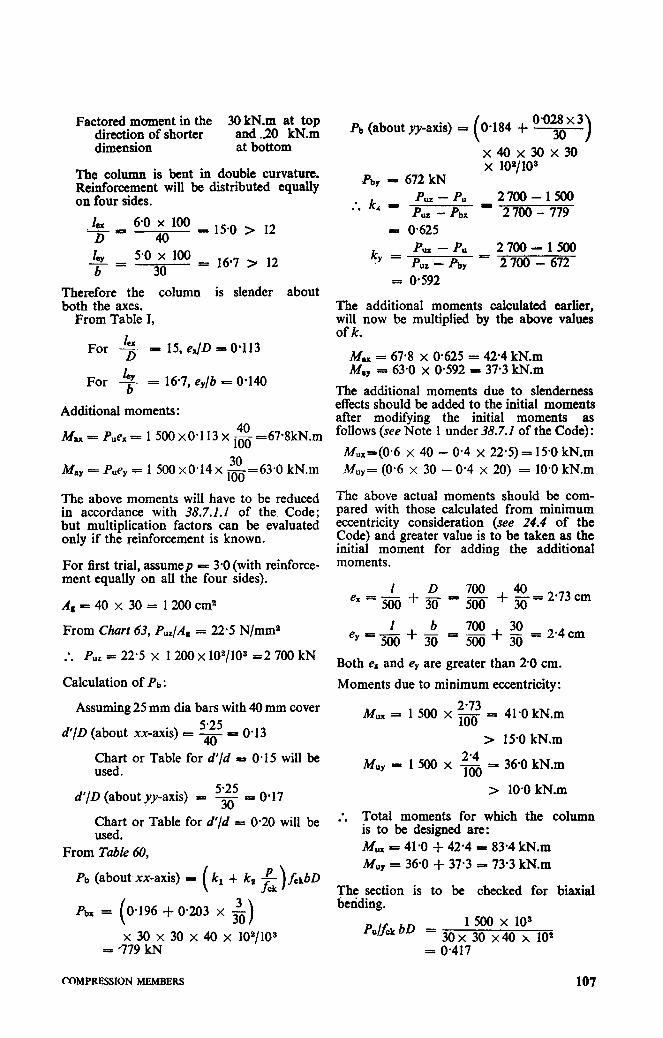
Factored moment in the 30 kN.m at top direction of shorter dimension
~tdJOcN.xn
The column is bent in double curvature. Reinforcement will be distributed equally on four sides.
Lx 6-o x 100 ‘- P D 40 = 15.0 > 12
cy= I 5.0 x 100 b 30
= 16-7 > 12
Therefore the column is slender about both the axes.
From Table I,
For Lz P 15, eJD = 0.113
lay For b = 167, e,/b = O-140
Additional moments:
M 1x = Puex = 1 500 x0-1 13 x & -67.8kN.m
May = Pue, = 1 500 x0*14x &=63*0 kN.m
The above moments will have to be reduced in accordance with 38.7.1.1 of the Code; but multiplication factors can be evaluated only if the reinforcement is known.
For first trial, assumep p: 3.0 (with reinforce- ment equally on all the four sides).
&-=40x 30= 1200cm2
From Chart 63, Puz/As = 22.5 N/mm2
- Pu . . = 22.5 x 1200 x 102/10s =2 700 kN
Calculation of Pb :
Assuming 25 mm dia bars with 40 mm cover
d’/D (about xx-axis) cs g = 0.13
Chart or Table for d’/d P O-15 will be used.
5.25 d’/D (about yy-axis) = 3. = 0.17
Chart or Table for d’/d = 0.20 will be used.
From Table 60,
Pb (about xx-axis) = (k, + k2 &rbD
3 0.196 + 0.203 X o
x 30 x 30 x 40 x 102/103 = -779 kN
Pb (about yy-axis) i 0.184 -+ O-028 x 3 30
x40x30x30 x 10*/1os
.pby - 672 kN
* k, I p -;b; I ‘;ym- 17r . .
= oG5
k Puz - Pu 2700-1500 .y = p “7. - pb y - 2 700 - 672
= o-592
The additional moments calculated earlier, will now be multiplied by the above values of k.
= 67.8 x O-625 = 42.4 kN.m :: = 63.0 x 0.592 - 37.3 kN.m
The additional moments due to slenderness effects should be added to the initial moments after modifying the initial moments as follows (see Note 1 under 38.7.2 of the Code) :
M,,=(O*6 x 40 - 0.4 x 22.5) = 15-O kN.m KY= (0.6 x 30 - 0.4 x 20) = 10.0 kN.m
The above actual moments should be com- pared with those calculated from minimum eccentricity consideration (see 24.4 of the Code) and greater value is to be taken as the initial moment for adding the additional moments.
&+$-7g 40 ex = - + 3o= 2*73cm
= 2.4 cm
Both e, and e, are greater than 20 cm.
Moments due to minimum eccentricity:
Mux = 1 500 x ‘g = 41.0 kN.m
> 15.0 kN.m
Muy - 1500x2’4 100 = 36.0 kN.m
> 10.0 kN.m
:. Total moments for which the column is to be designed are: MUX - 41.0 + 42.4 = 83.4 kN.m iu Uy = 36.0 + 37.3 = 73.3 kN.m
The section is to be checked for biaxial betiding.
Pul& bD = 1500 x 10s
30x 30 x40 x 102 = 0.417
COMPRESSION MEMBERS 107
i
Plfck - .g = 0.10
:. MUX1 = 0.104 x 30 x 30 x 40 x 40 x 103/10’
= 149.8 kN.m Refep; to ihart 46 (d’/D P O-20),
v cka = 0,096 2
:. M”Yl =0*096 x 30 x 40 x 30’~ 30 x 103/106
= 103.7 kN.m M”, 83.4 - ic - e 0.56 M”,, 149.8
MUY 73.3 - M Ic - 103.7 = 0.71
UYl
PulPu, = - 1500 2700
= 0.56
Referring to Chciit 64, the maximum allow- able value of M,,/M,,, corresponding to the above values of M,,/M,,, and PuIPuz is 0.58 which is slightly higher than’ the actual value of 0.56. The assumed reinforcement of 3.0 percent is therefore satisfactory.
A s = pbD/lOO - 3.0 x 30 x 40/100 L= 36.0 cm2
108


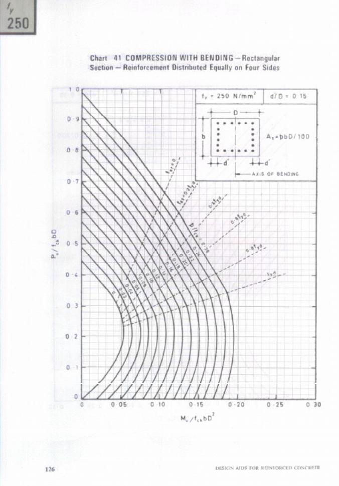

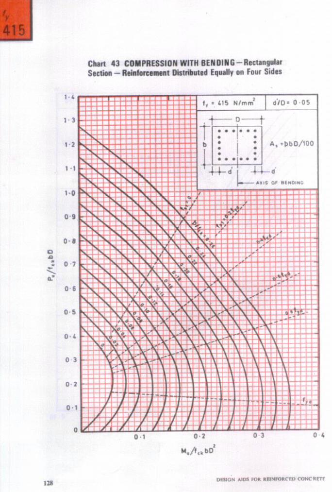
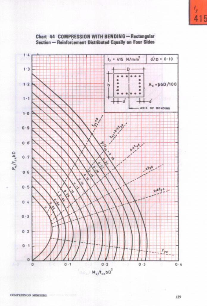
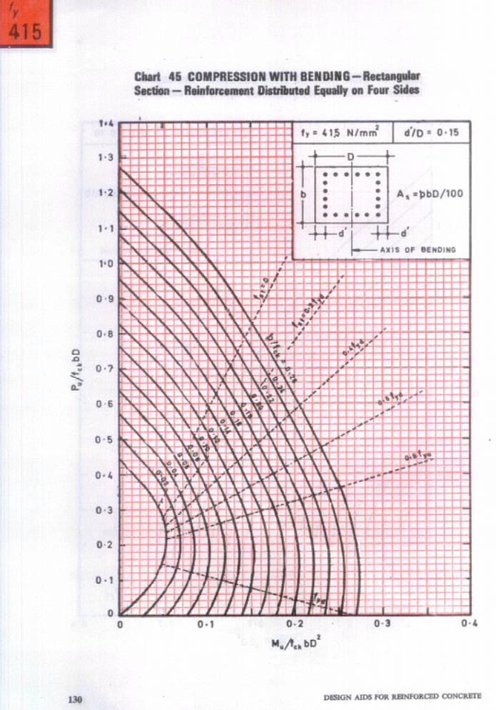


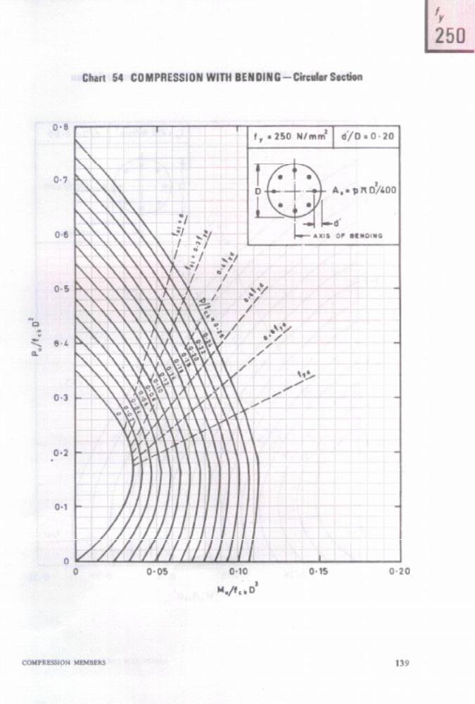

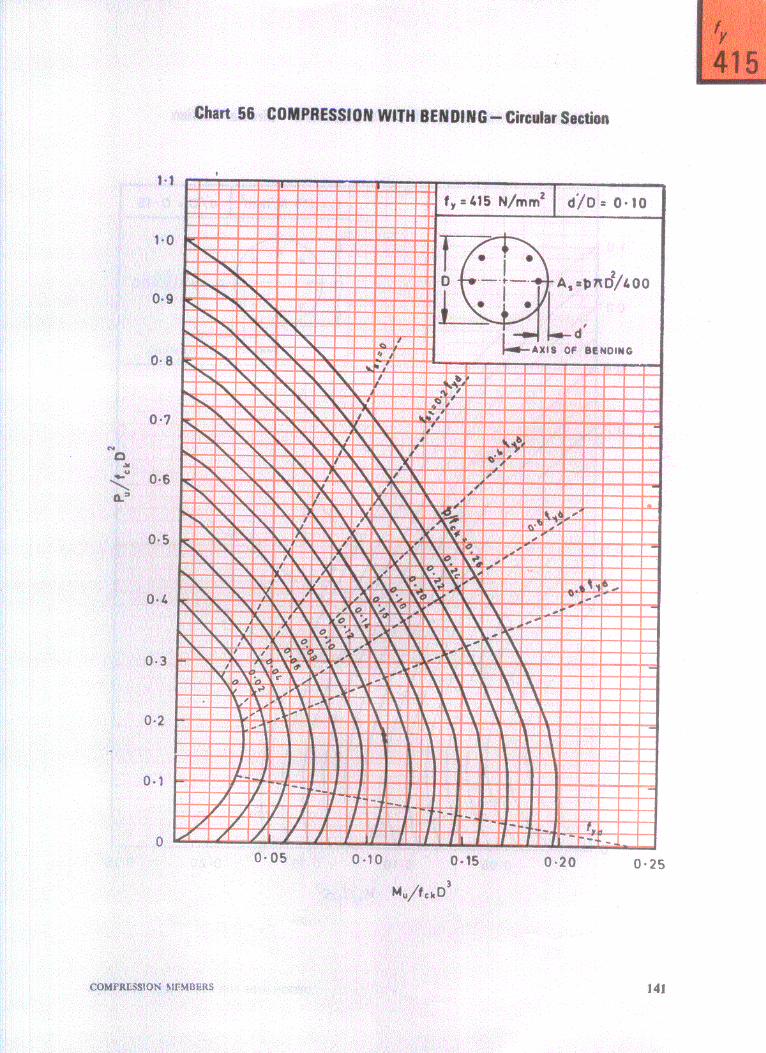


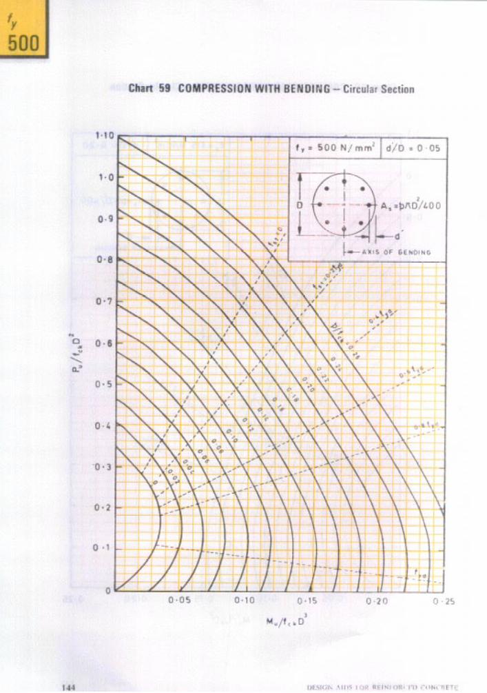
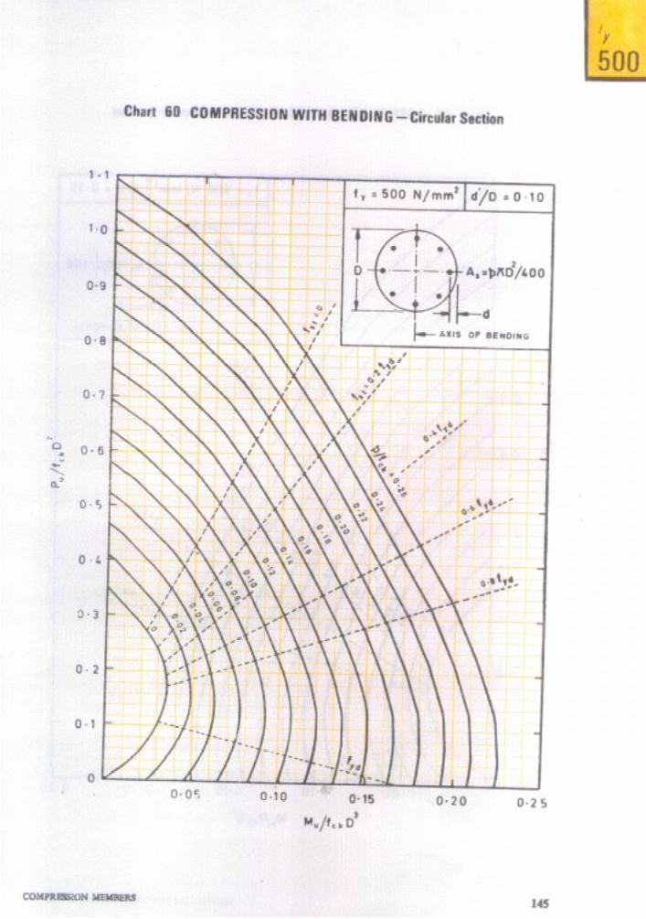
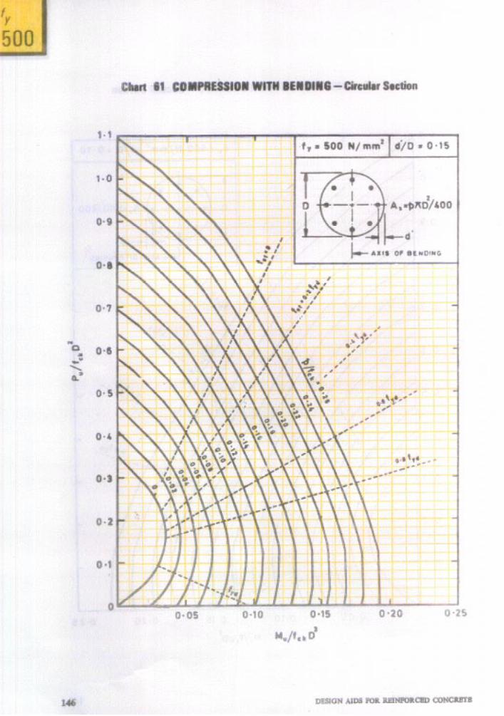
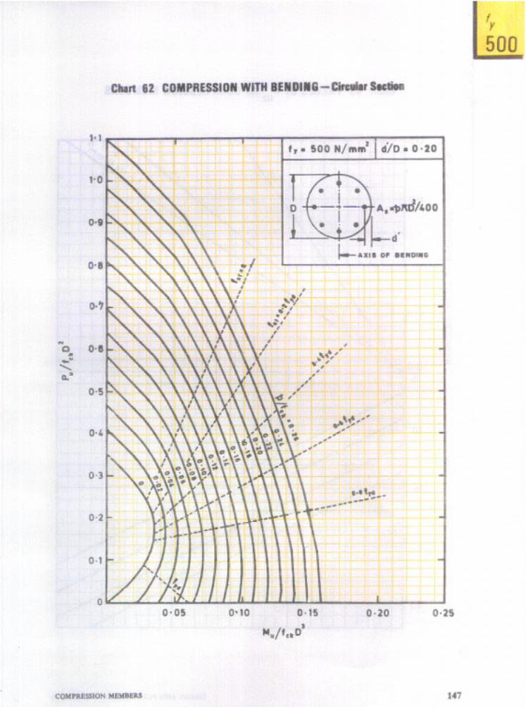

'Y
250 415 500 - f ck
15 20 25 30
Chart 63 VALUES OF Puz for COMPRESSION MEMBERS
ti i i i i i i i i i i i i i i i i i i IWi
148 ._ DESIGN AIDS FOR REINFORCED CONCRETE .a
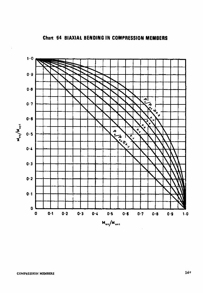
-.. .
Chart 64 BIAXIALBENDINGIN COMPRESSION MEMBERS
0 0.1 O-2 O-3 0.4 0.5 O-6 O-7 0.8 0.9 1.0
%/L
COMPRFSSIONMEMBERS
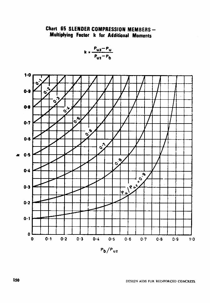
a 04
04
O-3
0*2
o-1
0
Chart 65 SLENDER COMPRESSION MEMBERS - Multiplying Factor k for Additional Moments
P k+ ur-pu
P UZ -Pe
150 DESIGN AIDS FOR REINFORCED CONCRl3-b


TABLE 60 SLENDER COMPRESSION MEMBERS-VALUES OF A
lktMgdW_:
Valora of k,
&ID r 005 WlO
9
015 OQQ
0219 om7 01% 0184
0172 @MO 0149 0.138
V@mof4
#ID fr r \
N,‘mrn~ O-05 0.10 &lS 020
COMPRESSION MEMBERS 171

As in the Original Standard, this Page is Intentionally Left Blank


As in the Original Standard, this Page is Intentionally Left Blank
Y”
4. SHEAR AND TORSION
4.f DESIGN SHEAR STRENGTH OF CONCRETE
*The design shear strength of concrete is given in Table 13 of the Code. The values given in the Code are based on the following equation:
where g =0.8 fck/6*89pl, but not less than 1.0,
and Pt = 100 A&&.
The value of ‘F~ corresponding to pl varying from 0.20 to 3.00 at intervals of 0.10 are given in Table 61 for different grades of concrete.
4.2 NOMINAL SHEAR STRESS
The nominal shear stress 7” is calculated by the following equation:
VU 7” = -
bd
where
V,, is the shear force.
When rv exceeds 7c, shear reinforcement should be provided for carrying a shear equal to Vu- Q bd. The shear stress rv should not in any case exceed the values of T~,~, given in Table J. (If T”> T~,~~, the section is to be redesigned.)
TABLE J MAXIMUM SHEAR STRESS w,mu
CON- GRADE Ml5 M20 M25 M30 M35 M40
Q., mu, N/mm’ 25 2% 3-l 3.5 3-l 40
4.3 SHEAR REINFORCEMENT
The design shear strength of vertical stirrups is given by the following equation:
v _ @87f,A,vd “I - sv
where
For a series of inclined stirrups, the value of Vup/d for vertical stirrups should be multiplied by (since i- coscc) where cc is the angle between the inclined stirrups and the axis of the member. The multiplying factor works out to 1.41 and 1.37 for 45” and 60” angles respectively.
For a bent up bar, V uI = 0*87fY ASv since
Values of V,,, for different sizes of bars, bent up at 45” and 60” to the axis of the member are given in Table 63 for two grades of steel.
4.4 TORSION
Separate Charts or Tables are not given for torsion. The method of design for torsion is based on the calculation of an equivalent shear force and an equivalent bending moment. After determining these, some of the Charts and Tables for shear and flexure can be used. The method of design for torsion is illustrated in Example 11.
Example 10 Shear
Determine the shear reinforcement (vertical stirrups) required for a beam section with the following data:
Ream size ‘30 x 60 cm Depth of beam acrn Concrete grade M 15 Characteristic strength 250 N/mma
of stirrup reinforcement Tensile reinforcement 0.8
percentage Factored shear force, Vu 180 kN
Assuming 25 mm dia bars with 25 mm cover,
d = 60 -T - 2.5 = 56.25 cm
Shear stress, 7” =i g -30 ~8p,$o,“,,
= l-07 N/mm*
A,” is the total cross sectional area of From Table J for M15, 7c,max = 2.5 N/mm2 the vertical legs of the stirrups, and T” is less than 7c,mu
sv is the spacing (pitch) of the stirrups. From Table 61, for P1=0.8, ~~20.55 N/mm*
The shear strength expressed as Vu/d are given in Table 62 for different diameters and Shear capacity of concrete section = Q bd spacings of stirrups, for two grades of steel. = 0*55 x 30 x 56.25 x 102/103=92*8 kN
SHEAR AND TORSION 175

Shear to be carried by stirrups, VU,== V, -~bd = 180 - 92.8 = 87.2 kN
V”, 87.2 -EL-- = d 5625
1.55 kN/cm
Referring to Table 62, for steelf, -250 N!mme. Provide 8 mm diameter two legged vertical stirrups at 14 cm spacing.
Example I I Torsion
Determine the reinforcements required for a rectangular beam section with the following data :
Size of the beam 30 Y 6Ocm Concrete grade M 15 Characteristic strength 415 N/mm2
of steel Factored shear force 95 kN Factored torsional 45 kN.m
moment Factored bending moment 11 S kN.m
Assuming 25 mm dia bars with 25 mm cover,
d = 60 - 2.5 - ‘G - 56.25 cm
Equivalent shear,
Vc = V-I- 1*6( f ,
45 595-t 1*6x m = 95-l-240 = 335 kN
Equivalent shear stress. V, 335 x 101
%e = Fd = 3. x 56.25 >r lo2 = 1.99 N/mm*
From Table J, for M 15, ‘F~,,,,.~ = 2.5 N/mm” ~~~ is less than sc.,,,-; hence the section does not require revision. From Table 61, for an assumed value of pt = 0.5,
T. = 0.46 N/mm* c T”=. Hence longitudinal and transverse reinforcc- ments are to be designed Longitudinal reinforcement (see 40.4.2 of the Code): Equivalent bending moment,
Me,.= M,C Mt *
= 115-J-79.4 = 194.4 kN.m
M,Jbd2 = 194.4x 10”
30 x (56.292 x 103 = 2.05 N/mma
Referring to Table I, corresponding to
Mujbdz .= 2.05
PI = 0.708
A,, = O-708 x 30 x 5625/100 = 1 l-95 cm*
Provide 4 bars of 20 mm dia (A*= 12.56 cm*) on the flexural tensile face. As Mt is less than MU, we need not consider Me, according to 40.4.2.1 of the Code. Therefore, provide only two bars of 12 mm dia on the compres- sion face, one bar being at each corner.
As the depth of the beam is more than 45 cm, side face reinforcement of 0.05 percent on each side is to be provided (see 25.5.1.7 and 25.5.1.3 of the Code). Providing one bar at the middle of each side,
Spacing of bar = 53.412 = 267 cm
Area required for each 0.05 x 30 x 26.7 bar= .- ,oo
= 040 cm*
Provide one bar of 12 mm dia on each side. Transverse reinforcement (see 40.4.3 of the Code) :
Area of two legs of the stirrup should satisfy the following:
1 Y&6cm
-m
-
W---30 cm-
b, = 23 cm k
I 7
6C 1
d, 953-4 cm
1
cm
,-FLEXURAL TENSION FACE
*
176 DESIGN AIDS FOR REINFORCED CONCREFE
Assuming diameter of stirrups as 10 mm da = 60 - (2.5 + l-O)-(2*5+0%)-53.4 cm b1=30-2(25+1.0)=23cm Aav (0*87&J 45 x 10’
S” -23 x 53.4 x lOa
+25 x 95 53.4 x IO? x 10 -366.4-l-71.2
= 437.6 N/mm P 438 kN/cm
Area of all the legs of the stirrup should satisfy the condition that A& should not
From Table 61, for tensile reinforcement percentage of @71, the value of o is O-53 N/mm’
- (I.99 - 0.53) 30 x 10
II 438 N/mm -438 kN/cm
Nom-It is only a coincidence that the values of Aav (@87/rllSv cdcuhted by the hvo cqlm- tions 8rc the srmc.
Referring T&e 62 (forfr - 415 N/mm’). Provide 10 mm + two legged stirrups at 12.5 cm spacing.
According to 25.5.2.7(u) of the Code, the spacing of stirrupa shall not exceed xl, (x, C yJ4 and 300 mm, where x1 and arc the short and long dimensions of
1 tL
stirrup.
xl - 30 - 2(2.5 - O-5) = 26 cm y,r60-2(25-05)=56cm
(xl f y&/4 - (26 i- 56)/4 - 20.5 cm
10 mm + two legged stirru at 12.5 cm spacing will satisfy all the cod $ requirements.
SHEAR AND TORSION 177
f ck
15 20 25 30 35 40
-
pt
TABLE 61 SHEAR - DESIGN SHEAR STRENGTH OF CONCRETE, TC) N/mm2
fck, N/mm*
I - --. , IS 20 25 30 35 40
0.80
%
1.10 1.20 1.30 1’40 1.50
1*60 1.70
:z 2.00
210 220 2.30
f %
E E 3.00
032 0.33 0.33 0.33 0.34 034 0.38 0.39 0.39 0.40 0.40 0.41 0.43 8:Z 0.45 045 046 046 0.46 0.49 0.50 0.50 0.51
0.50 0.51 0.53 0.54 0.54 0.55 0.53 0.55 056 0.57 0.58 059 0.55 0.57 0.59 iE 0.61 062 0.57 8:Z 0.62 O%O 0.64 066
8:; 0.65 0.68
0.62 ~~~ 0.66 0.68 069 0.70 0.63 0.69 0.70 0.72 0.73 065 0.68 0.71 0.72 0.74 0.75 0.67 0.70 072 0.74 076 0.77 068 072 0.74 076 0.78 0.79
0.69 073 076 0.78 0.80 0.81 0.71 0.75 0.77 0.80 0.81 0.83 0.71 076 0.79 0.81 0.83 0.85 0.71 077 0.80 0.83 085 086 0.71 0.79 0.82 084 0.86 088
0.71 0.80 0.83 086 0.88 090 071 0.81 0.84 087 0.89 0.91 0.71 0.82 0.86 088 0.91 0.93 0.71 082 0.87 092 0.94 0.71 0.82 0.88 ;I: 0.93 0.95
0.71 0.82 X:E 0.92 094 097 0.71 0.82 0.93 0.96 0.98
x::: @82 0.82 091 0.92 0.94 0.95 097 0.98 0.99 l*oO 0.71 0.82 0.92 0.96 0.99 1.01
178 DESIGN AIDS FGR RHNFGRCBD CGNCmB
'v
250 415
STIRRUP SPmNO,
em
5
, 6
1537 l-367 -1.230
TABLE 62 SHEAR -VERTICAL STIRRUPS
Values of VW/d for two legged stirrups, kN/cm.
J, = 250 N/mm2
DIAMEIZR, mm
8 10
4373 6833 3644 3.124 6E 2733 4271 2429 3.796 2186 3,416
1.988 3.106 1.822 2847 1682 2628 1.562 1.458 ::z
::E 2135 2010
1.215 1.898 1.151 1.798 1.093 1.708
0.875 1.367 0.729 1.139 0625 0.976 0.547 0.854 0.486 0.759
-7
12
4472 4100 3.784
Et
3.075 2894 2733 2589 2460
/x = 415 N/mm*
DIAMETER, mm
’ 6 8 10
4083 3403
t:;:: 2269 2042
I.856 1.701 1.571 1.458 1.361
1.276 1.201 1.134 1.075 1.020
0.817 0681 0’583 0.510 0.454
7.259 11.342
f :% 9452 8.102 4537 7089 4.033 6302 3.630 5.671
3.299 5.156 3.025 4726 2792 4363 2593 4051 2420 3.781
2269 3.545 2135 3.336
:8:8 3.151 . 2985
1.815 2.836
l-452 1.210 :z 1.037 1.620 0907 1.418 0.807 1.260
7424 6806
L% 5445
5.104 4804
t:;:;: 4083
TABLE 63 SHEAR- BENT-UP BARS
Values of Vu, for singal bar, kN
BAR /i - 250 N/mm* fy = 415 N/mm2 Dm, I , I
mm a = 45’ a=60° Q i= 45” >
a=60°
:; 1208 1739 21.30 1479 20.05 28.87 2456 35.36
:B” 30.92 3914 47.93 37.87 51.33 64.97 %E 20 48.32 5918 SO.21 98.23
5846 7160 75.49 9246 94.70 115.98
123.69 151.49 15654 191.73
97.05 _. __ 125.32 15720 205.32 25986
118.86
:;;*z . 251.47 318-27
NOTE- a is the angle between the bent-up bar and the axis of the member.
8HEAR AND TOIlsION 179

As in the Original Standard, this Page is Intentionally Left Blank

As in the Original Standard, this Page is Intentionally Left Blank
5. DEVELOPMENT LENGTH AND ANCHORAGE
5.2 DEVELOPMENT LENGTH OF BARS
The development length Ld, is given by + es Ld = ~ 4 Tbd
where 4 is the diameter of the bar,
a, is the stress in the bar, and 7bd is the design bond stress given in
25.2.1.1 of the Code.
The value of the development kngth corresponding to a stress of 0937 fY in the reinforcement, is required for determining the maximum permissible bar diameter for
positive moment reinforcement [see 25.2.3.3(c) of the Code] and for determining the length of lap splices (see 25.2.5.2 of the Code). Values of this development length for diffe- rent grades of steel and concrete are given in Tables 64 to 66. The tables contain the development length values for bars in tension as well as compression.
5.2 ANCHORAGE VALUE OF HOOKS AND BENDS
In the case of bars in tension, a standard hook has an anchorage value equivalent to a straight length of 16# and a 90” bend has an anchorage value of 84. The anchorage values of standard hooks and bends for different bar diameters are given in Table 67.
DEVIXWMENT LRNGTH AND ANCHORAGE 183
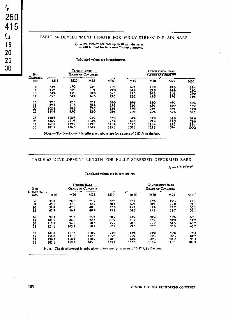
'v
250 415 f ck
15 20 25 30
TABLE 64 DEVELOPMENT LENGTH FOR FULLY STRESSED PLAIN BARS
Jj = 250 N/mm* for bars up to 20 mm diameter. = 240 K/mm’ for bars over 20 mm diameter.
Tabulated values are in ccatimatns.
TENSION BARS COMPRESSION BARS BAR GRADE OF CONCRETE GRADE OF CONCRETE
DIAMETER, f-A----, mm Ml5 M20 M25
, M30 Ml5 M20 M25 -M301
x 43.5 326 % 23.3 31.1 21.8 290 261 348 21.8 18.6 174
10 544 453 38.8 23.2
363 43.5 z:: 65.3 544 46.6
290 12 435 522 435 348
:: 87.0 97.9 725 81.6 621 699 653 58.0 696 78.3 65.3 5&O 497 559 zt z 108.8 114.8 z.76 777 820 725 766 870 91.9 725 766 621 65.6 58.0
61.2
25
;; 36
1305 108.8 93.2 870 104.4 87.0
146.2 :z:x
1392 121.8 1193 lW4 111.4 974 133.6 1169 974 1566 1342 125.3 150.3 f::::
NOTE -The development lengths given above ara for a stress of @87/y in the bar.
746 696
95.5 835 % 107.4 10&2
_
TABLE 65 DEVELOPMENT LENGTH FOR FULLY STRESSED DEFORMED BARS
fy PI 415 N/mm*
Tabulated values are in cantimetrcs.
TENSION BARS COMPRESSION BARS
BAR GRADE OF CONCRETE GRADE OF CONCRETE DIAMETER, C- A- -- I -
Ml5 M20 M25 M30 Ml5 M20 M25 M30
33’8 28.2 45.1 37.6 564 47-o 677 564
242 322
22.6 271 391 361 37.6 45.1 45.1 542
193 18.1 25.8 241 322 30.1 38.7 361
1% 112.8 124-l
75.2 846 940
103.4
z:: SC 827
72.2 81.2
z*:
141.0 1580 180.5 203.1
117.5
1 :A:: 169.3
100.7 940 112.8 94.0 1128 105.3 126.4 105.3 128.9 120.3 144.4 120.3 145.0 135.4 162.5 135.4
51.6 48.1 58.0 542
%Z %“z
806 75.2
1E 2:: 1161 108.3
Nora-The development lengths given above are for a stress of 087fy in the bars.
184 DESIGN AIDS FOR REINFORCED CONCRETE


TABLE 67 ANCHORAGE VALUE OF HOOKS AND BENDS
Tabulated values are in centimetres.
BAR DIAMETER, mm
Anchorage Value of hook Anchorage Value of 90” bend
6 8 10 12 16 18 20 22 25 28 32 36
9.6 128 160 192 25.6 28.8 320 35.2 40.0 448 51.2 57-6
4.8 6.4 8-O 9.6 12.8 14.4 16.0 17.6 20-O 22.4 25.6 28.8
-I--- 4 cb mir
_L_-
STANDARD HOOK STANDARD 90’ BEND
STANDARD HOOK AND BEND
Type of Steel Min Valye of k
Mild steel 2
Cold worked steel 4
NOTE 1 -Table is applicable to all grades of reinforcqment bars.
No,rli 2 - Hooks and binds shall conform to the details given above.
186 DESIGN AIDS FOR REINFORCED CONCRETE

As in the Original Standard, this Page is Intentionally Left Blank

6. WORKING STRESS DESIGN
6.1 FLEXURAL MEMBERS
Design of flexural members by working stress method is based on the well known assumptions given in 43.3 of the Code. The value of the modular ratio, m is given by
280 93.33 m E-E-
3 acbc acbc Therefore, for all values of acb we have
m acbc = 93.33
b;bc
7 -. l-k T-1
FIG. 9 BALANCED SECTION (WORKING STRESS DESIGN)
6.1.1 Balanced Section (see Fig. 9)
Stress in steel = ast =maLbc(+-1)
1 -= k
k= 93.33
as( f- 93.33 The value of k for balanced section depends only on qt. It is independent of a,bc. Moment of resistance of a balanced section is given
by hfbal = yach k( 1 - f ); The values
of Mbal/bd2 for different values of U&c and asI are given in Table K.
TABLE K MOMENT OF RESISTANCE FACTOR M/b@, N/mm* FOR BALANCED
RECTANGULAR SECTION
=cbc ‘%I, N/mm* N/mm’ c +‘-
140 230 275
5.0 0.87 0.65 0.58 7-o 1.21 0.91 O-81
8.5 147 1.11 0.99
10-o 1.73 1.30 l-16
Reinforcement percentage Pt,bal for balanced section is determined by equating the com- pressive force and tensile force.
a,h kdb _ _ PI,~I bd as1 2 100
hbal = 50 k.a,a
a t .
The value of pt,w for different values of a,bc and a,t are given in Table L.
TABLE L PERCENTAGE OF TENSILE REINFORCEMENT P..,,., FOR SINGLY
.,“_.
REINFORCED BALANCED SECTION (Clause 6.1.1)
$&ma esl N/mm*
Gil L , 230 275
5.0 0.71 0.31 O-23
7.0 l-00 0.44 0.32
8.5 1.21 053 0.39
10.0 1.43 0.63 O-46
6.1.2 Under Reinforced Section
The position of the neutral axis is found by equating the moments of the equivalent areas.
bkdz pt bd 2
= loo m (d - kd)
bd2 7 = bd2 ‘$ (1 - k)
k2 = p$(l - k)
k2 + !$- !!!=o.
The positive root of this equation is given by
k = Ptm + -- p2,m2 100 J
+ ptm F - (100)” 50
This is the general expression for the depth of neutral axis of a singly reinforced section. Moment of resistance of an under-reinforced section is given by
Values of the moment of resistance factor M/bd2 have been tabulated against pt in
189 WORKING STRm DESIGN
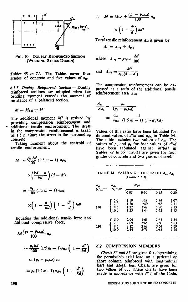
FIG. 10 DOUBLY R~r~~onci?n SECTION (WORKING Smm.s D~SGN)
Tables 68 to 71. The Tables cover four grades of concrete and five values of uu.
6.1.3 Doubly Reinforced Section - Doubly reinforced sections are adopted when the bending moment exceeds the moment of resistance of a balanced section.
M=b&i-M’
The additional moment M’ is resisted by providing compression reinforcement and
0 additional tensile reinforcement. The stress in the compression reinforcement is taken as I.5 m times the stress in the surrounding concrete.
Taking moment about the centroid of tensile reinforcement,
M’ = -ldc PC bd(1.5 m - 1) ucbc
x (1 -;)a&
To& tensile reinforcement A,l is given by
Ast = AM, -f- Astt
where Atu = pl,bPI &f 100
and A,Q =
The compression reinforcement can be ex- pressed as a ratio of the additional tensile reinforcement area Altp.
USI 1 = Qcbc (1.5 m - 1) (l-d’/kd)
Values of this ratio have been tabulated for different values of d’/d and ucbc in Table M. The table includes two values of ust. The values of pt and pc for fear values of d’/d have been tabulated against’ M/bd’ in Tables 72 to 79. Tables are given for four grades of concrete and two grades of steel.
I +& (1.5m - 1) uck
x(1 -$)(I-;)bd’
Equating the additional tensile force and dditional compressive force,
Xi k$! (1.5 m - l)U&( l-2)
or (pt - pt,bd olt
=pc (1*5m-l)ucbc (l-ii)
TABLE M VALUES OF THE RATIO A&,,, (Clause 6.1.3)
%t “cbc d’ld
N/mm’ N/mm’ m-- 0.15 0.20
5.0 1.19 1.38 l-66 2.07 1.20 I.68 2.11
140 I ;:y i 10.0
l-22 % 1.70 213 1.23 l-44 1.72 2.15
;:g 2.61 2.65 3.60 3.55 5.54 5.63
2.12 2.68 214 2.71 ;I$ :*:I: .
6.2 COMPRESSION MEMBERS
Charts 86 and 87 are given for determining the permissible axial load on a pedestal or short column reinforced with longitudinal bars and lateral ties. Charts are given for two vrdues of 0%. These charts have been made in accordance with 45.1 of the Code.
190 DESIGN AIDS FOR REINFORCED CONCRETE
According to 46.3 of the Code, members subject to combined axial load and bending designed by methods based bn elastic theory should be further checked for their strength under ultimate load conditions. Therefore it would be advisable to design such members directly by the limit state method. Hence, no design aids are given for designing such members-- by elastic theory.
Tables 81 and 82 are given for design of shear reinforcement.
6.4 DEVELOPMENT LENGTH AND ANCHORAGE
The method of calculating development length is the same as given under limit state design. The difference is only in the values of bond stresses. Development lenaths for
6.3 SHEAR AND TORSION plain bars and two grade; of deformed bars
The method of design for shear and torsion are given in Tables 83 to 85.
by working stress method are similar to the Anchorage value of standard hoolcs and limit state method. The values of Permissible bends as given in Table 67 are applicable shear stress in concrete are given in Table 80. to working stress method also.
WORKlNC3 STRESS DESlCiN 191

As in the Original Standard, this Page is Intentionally Left Blank
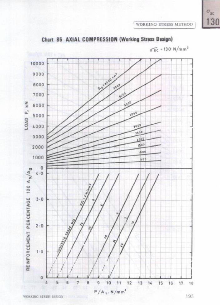
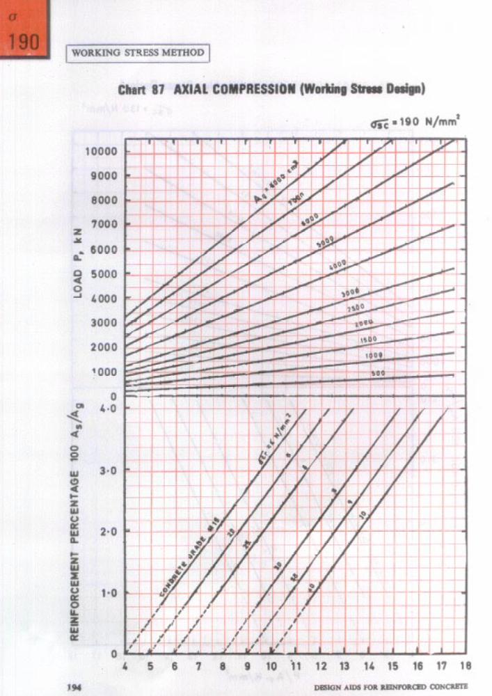
%t
130
I WORKING STRESS METHOD 140 190 230
TABLE 68 FLEXURE - MOMENT OF RESISTANCE FACTOR, iU/bda, N/mm* FOR SINGLY REINFORCED SECTIONS 275
130
0,146 O-158 O-170 O-181 O-193
0.205 0.216 O-228
8’::: .
O-262
::z o-297 O-308
O-319 O-331 O-342 O-353 0’364
O-376 O-387 O-398
:z
0431 o-443
ez O-476
O-487 O-498
190
x:2: O-248 O-265 O-282
O-299 O-316 O-333
x’::; .
O-383 0400 0.417 0.433 O-450
0.467 O-483 Oao @516 @533
0.631 0.647 O-663 O-679 0.695
O-711 0.728
230
O-258
Ei . O-321 O-341
O-362 O-383
Es . 0444
275 pt
est. N/mma f L- 50 . 130 140 190 230 275
0.47 0.542 0.583 0.48 O-553 0.595 O-49 O-564 O-607 0.50 O-574 O-619 O-51 0.585 0.630
@52 0.5% O-642 O-53 O-607 O-654 O-54 0,618 O-665 0.55 0.629 0x77 0.56 OTi40 O-689
O-650 O-700 O-661 O-712 0:672 0.724 O-683 0.735 O-693 O-747
0.62 0.63
x:s O-66
0.704 O-758 O-715 O-770 0.726 O-781 O-736 O-793 0.747 O-804
O-758 0.768 O-779
X:E
X:iE 0’839 O-850 O-862
O-811 O-821
:ii; . O-853
O-77 O-864
z; 8’0;: . O+O 0.895
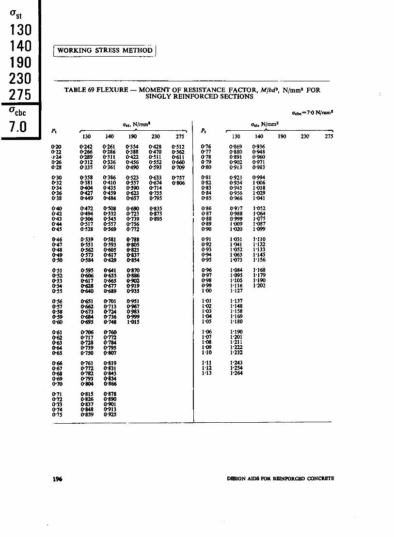
%t
130 140 190 230 275 %bc
70 .
1 WORKING STRESS METHOD 1
TABLE 69 FLEXURE - MOMENT OF RESISTANCE FACTOR, M/hP, N/mm* FOR SINGLY REINFORCED SECTIONS
us:, N/mm*
130 140 190 230 275 -
O-242 O-266 O-289
:::: .
O-358 O-381
:zi O-449
0.428 0.470 0.511 @552 O-593
O-523 O-633 O-557 O-674
x’z!i . z:: O-657 O-795
O-757 O-806
8Z .
iFg .
O-539 O-551 O-562 O-573 O-584
O-690 O-723 0.739
X’Ei .
:z O-821 0837 O-854
O-835
x::;:
O-581 O-593 @605 O-617 0.629
O-641 O-653
:zE OS89
O-651
:z .
:z
@701 O-713
x! . O-748
O-951 O-967 O-983
SE
0706 O-717 O-728 0.739 O-750
O-760
:z O-795 0807
O-761
K& .
O-804
0.815 O-878
X’E . t’E . Om8 O-913 O-859 O-925
pt
O-76 O-77 0.78 O-79 0.80
O-81 O-82 0.83
8::
O-86 O-87 O-88 O-89 O-90
O-96 O-97 O-98 099 1.00
130
O-869 @880 0.891
8ZZ
l-031 l*!Ml l-052
:iE
l-084
::z: 1.116 l-127
::::I 1.158 l-169 l-180
140 190 230 27i
O-936 0948 O-960 0.971 O-983
o-994
F% 1.029 l-041
l-052 l-064 - __. l-075 l-087 l-099
l-110 l-122 l-133 l-145 l-156
1.16 1.179 l*l!bl 1.202
1% DElION AIDS FOR RRINKRkCRD CDNCRR’I’B

1 WORKING STRESS METHOD (
TABLE 70 FLEXURE-MOMENT OF RESISTANCE FACTOR, hf/bd¶, N/mm* FOR SINGLY REINFORCED SECTIONS
pt ’ 130 140 190 230 275-
O-244
8::;: O-314 O-337
0.262 0.288 O-313
Ei
O-30 0.361 O-32 O-394 0.34 O-407 O-36 O-430 O-38 O-453
O-388 O-413
tee @488
O-476 O-498 O-521 O-544 O-567
O-512
x:::: O-586 0.610
O-50 0.52 O-54 056 O-58
O-589 O-612 O-634
x:::3
O-634 O-659 0%83 0.707 0.731
0.701 0.723 0.746 O-768 O+Ml
0.70 0.812 O-875 O-72 O-834 O-898 O-74 0.856 0.922 O-76 0.878 0946 0.78 0900 0.969
O-80 O-82 O-83 O-84 0.85
XE O-955 O-966 0.977
0993
:% .
:zE
8:: O-88 O-89 090
0.987 0998 ltM9 l-020 l-031
l-042
E: . l-074 l-085
1.122 l-134 1.145 l-157 l-169
a, N/mm’
x::;: O-425 O-459 O-493
O-431 O-515 0.96 O-473 O-565 0.97 @514 0.615 0.98 O-556 O-664 O-99 0.597 O-714 1.00
O-527 O-638 O-561 0.679 O-595 O-720 O-628 0.761 O-662 O-801
Ow2
::tiz O-962 l-002
1.042 l-082
l-025 l-057 l-090
::i::
l-187 l-219
O-763 O-812 O-861
E
pt
1.11 1.12 1.13 1.14 1.15
1.16 1.17 1.18 1.19 1.20
1.21 1.22 1.23
E
1.26
::f; i-29 1.30
1.31
:::z
:*:: .
1.36 1.37
’ 130
1.096
x: 1.128 1.139
::E 1.171 1.182 1.193
1.203
::z 1.236 1.246
1.310 l-321 1.332
::E:
1.364 1.374
:::;: 1406
1.417 1.427 1.438 1448 1.459
1469 1,480 1.491 1 a501 I.512
1.522 1.533
140 190 230 275
1.180 1.192 1.203 1.215 1.227
1.238 1.250
l-411 l-423 1.434
:‘% .
1468
130 140 190 230 275 %bc ’
85 .
WORKING STRESS DESIGN 197
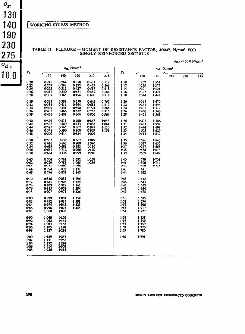
%t
130 140 190 230 275 %bc
100 .
I TABLE 71 FLEXURE - MOMENT OF RESISTANCE FACTOR, M/bd2, N/mm2 FOR SINGLY REINFORCED SECTIONS
230
O-433 0.475 O-517
X:E
OTi42 O-683 O-724
ALE
0.847
x’% . O-969 1*009
1.049
;:g
l-210
1.250 l-289
Pl ’ 130
I.10 1.257 1.12 l-279 1.14 1.301 I.16 1.322 1.18 l-344
1.365 1.387 1.408 l-430 l-451
1’30 l-473 1’31 l-483 l-32 l-494 l-33 l-505 1’34 l-515
l-35
:::4 1.38 l-39
1.526 l-537 1.547 l-558 1.569
;:g .
1.43 l-44
1.45 l-632 1.46 1.643 1.47 1.653 l-48 l-664 1.49 1.675
1.50 1.51 1.52 1.53 1.54
1.685
EE . l-717 l-727
135 1.56
:z . 1.59
1.738 l-749 1.759 1.770 l-780
l-60 l-791
WC = 10.0 N/mm’
USI, N/mm*
140 190 230 27;
%i 1.401 1.424 1’447
1.470 1.494
E . l-563
1.586 l-597
:z 1,632
1.643 l-655
t%i . l-689
1’701
t ::i:
DESIGN AIDS FOR RBINFORCED CON-
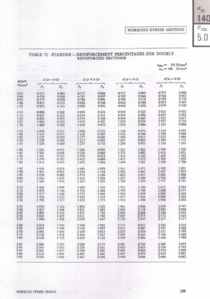

1 WORKING STRESS METHOD 1
MJbd a N/mm2
d’Jd is 0.05 I 3
pt PO .
1.22 1 a05 1.25 l-028
:::i KG 140 l-140
oaK O-033 O-078 O-124 O-169
1.45 1.178 150 1.216 1.55 1.253 l-60 1.291 l-65 l-328
1.70
::ii l-85 1.90
::z ::z 1441 O-531 1.479 0.576 l-516 0.621
1.95 2.00 2.05 2.10 2.15
O-666 0.712 O-757 @802 O-847
z 2.30 2.35 240
: ::;3
::i:: 1.892
Ef 0.983 l-028 l-073
245 2.50 255
E
t:;zt 2005 2.043 2080
1.119 1.164 l-209
1::;;
2-70 2-118 l-345 2’75 2.155 1.390 280 2193 l-435 285 2231 l-480 290 2268 1.526
295
::z 3.10 3.15
::z
:::: 340
2306 l-571 2343 l-616 2381 1.661 2.419 1 a707 2.456 1.752
2.494 2531 2569
f:fg
1.797 I.842
f:E 1.978
TABLE 73 FLEXURE - REINFORCEMENT PERCENTAGES FOR DOUBLY REINFORCED SECTIONS
d’/d pi O-10
pt PO- pt PC p, PC -
lTM6 l-031 l-073 1*:15 l-157
X:E O-123 O-193 0.264
1.006 0.013 1.033 oa69 l-077 O-163 l-122 O-257 1.167 0.351
1.188 1228 l-267
::z::
0.264 I.199 O-319 1.241 O-375 1.283 0.431 l-325 O-486 1.367
0.335
:% 0.547 O-618
1.211 0.445 1.255 0539 l-301 0.633 1.345 0.727 1.390 0.821
1.386 1.426 1.466 1.505 1.545
:::ii 0,653 0.709 0.765
1409 0.689 1.435 0.915 1.451 O-760 1.479 1009 1.493 0.830 1.524 l-103 1.535 0901 l-568 1.197 l-577 0.972 l-613 l-291
1.585 1.624
Kz I.743
O-821 1.619 1 a43 1.658 1.385 0.876 1.661 1.113 1.702 1.479 O-932 l-703 1.184 1.747 1.573 O-988 l-745 1.255 1.792 1.667 l-043 1.787 I.326 1.836 1.761
l-783 1.823 l-862 1902 l-942
1.099 1.155
::ti: 1.322
1.829 I.396 1.881 1.855 1.871 1.467 1.926 1.949 1.913 l-538 1.970 2.043 l-955 l-609 2.015 2.137 l-997 1.680 2.060 2.231
1.981
Et 2101 2140
1.378 2.039 1.750 2.104 2.325 1.433 2.081 1.821 2.149 2.419 1.489 2123 l-892 2.193 2.513 1.545 2165 l-963 ’ 2.238 2.607 l%OO 2-207 2.033 2283 2701
2180
3% 2.299 2339
1.656 1.712
:34: 1.879
2.249 2.104 2.291 2.175 2.333 2.246 2375 2.316 2-417 2387
‘2.327 2.372
::t :: 2506
2.795 2.888 2.982 3.076 3.170
2378 1.934
3% ::Ez 2497 2.102 2-537 2.157
2.459 2.458 2501 2-529 2.543 2.599 2585 2.670 2.627 2741
2.551 2-595
;zg
3.264 3.358 3.452 3.546 3-540
2.577 2.213 2.669 2.812 2.774 3.734 2.616 2.269 2.711 2883 2818 3.828 2.656 2324 2.754 2.953 2.863 3.922 2696 2.380 2796 3.024 2908 4.016 2-735 2.436 2.838 3.095 2-952 4.110
d’ld = 0.15 d’/d = 0.20 r- -A-------\
6dc = 7.0 N/mm2 qt = 140 N/mm2
200 DESIGN AIDS FOR REINFORCED CONCRETE
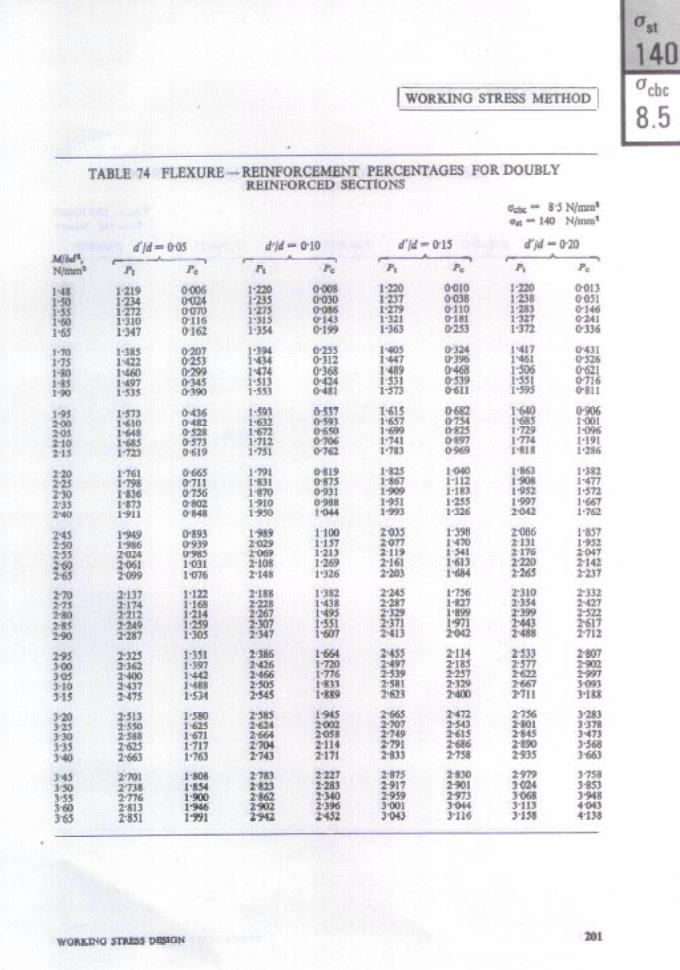

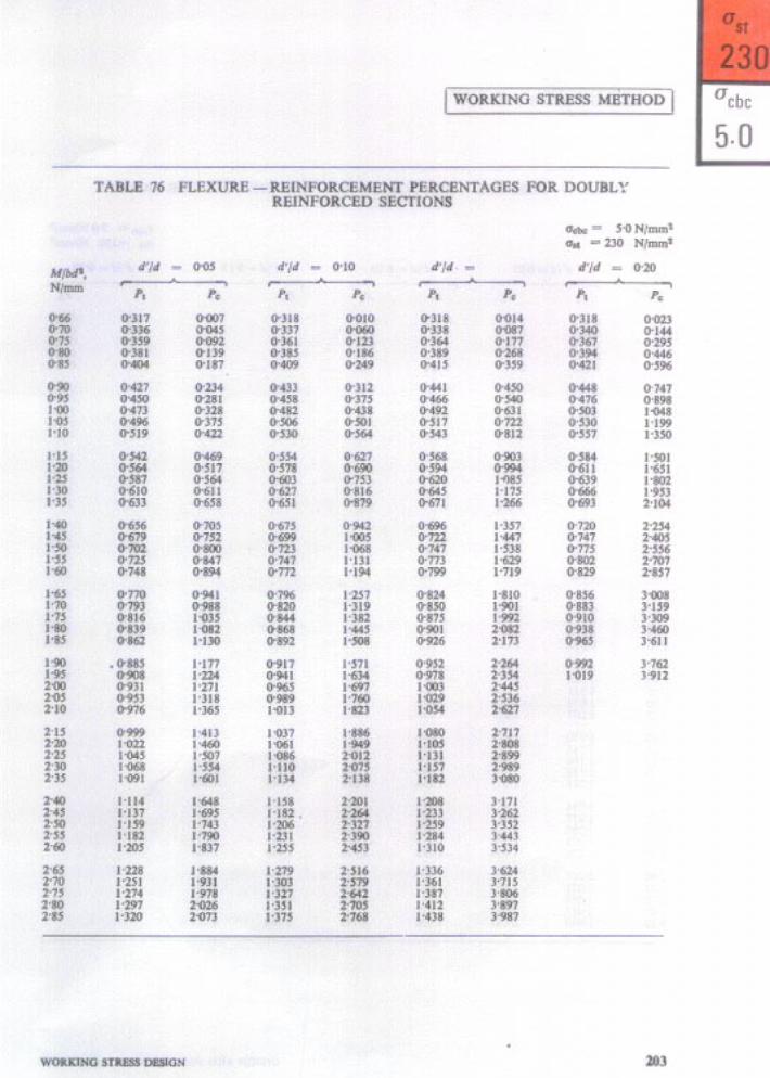
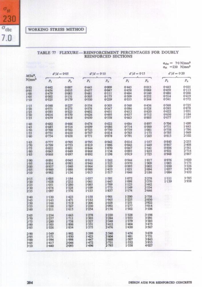
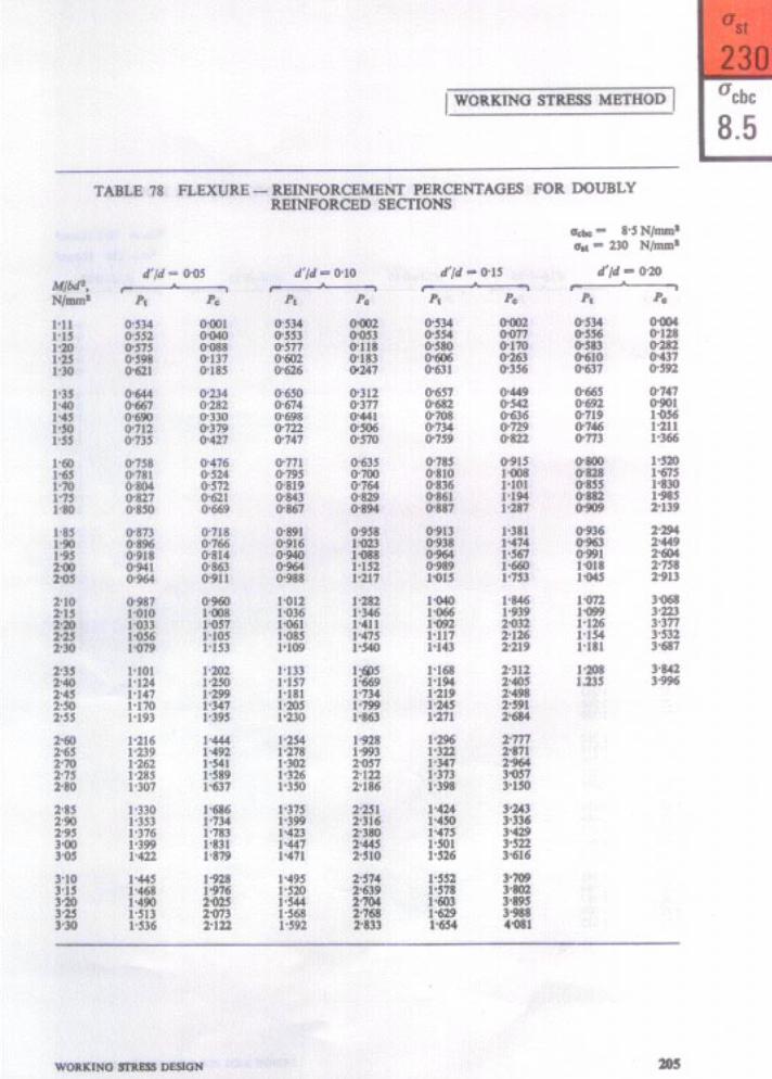
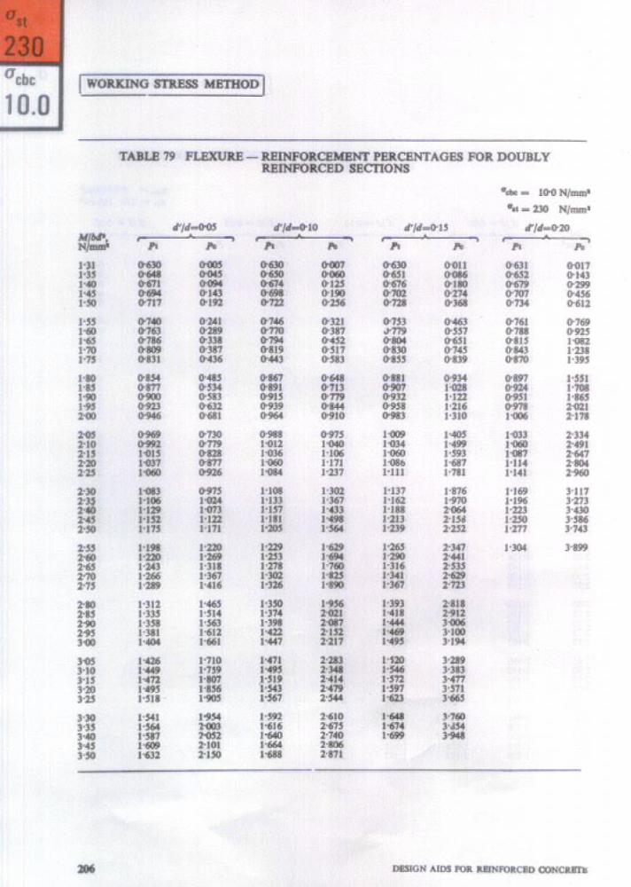
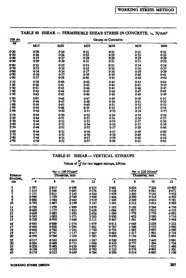
1 WORKING !3T@ESS METHOD 1
TABLE 80 SHEAR - PERMISSIBLE SHEAR STRESS IN CONCRETE, sc, N/mm*
M30
o-21 O-25
E 033 O-36 O-38 0.39 o-41 0.43
E
gz
0.49
8:: O-52 O-53 O-54 0.54 0.55 @56 o-57
x::: O-59 O-59
M35
O-21 O-25
LE O-34
XG 040 O-42 O-43 O-45
E O-49 o-50 O-51 0.52 0.53 O-54 O-55 O-56 O-57
iE: O-59
la40
O-21 0.25
iz
:3$ O-39 O-41 O-42 O-44 O-45 0.47 O-48 O-49 851 O-52 0.53 O-54 0.55 O-56 @57 O-58 0.59 O-60
8::
:::i
STIRRUP sPAuNo,
col
: 7
x 16
:: 13
TABLE 81 SHEAR - VERTICAL. STIRRUPS
Values of 9 for hvo legged stirrups, kN/cm
Gv 3: MN/mm* UN - 230 N/mma Dmmnm, mm I)l-. mm
l-979 1.863 I -759 1.667 l-583 1.267 l-056 0905
:z
2081 1 a734
f’ii! 1:156
WOltKlNO STRBSS DSlCiN 207

1 WORKING SfRESS METHOD 1
TABLE 82 SHEAR - BENT UP BARS
Valuewf V, for single bar, kN
%V = 140 N/mm* up to 20 mm diameter = 130 N/mm’ over 20 mm diameter
, 0=4S0
b a=60°
778 1120 lP90 25-19 31.10
9.52 13.71 iii*%3 2438 3270 3086 41.39 38.09 51.09
E . 93.57
6P32 PO-54
11460
%v= 230 N/mm’
NOTE - a is the an6 between the bent up bar and the axis of the member.
r- a=450
1277
61.82 7Pa3
100-14 130-80 16554
TABLE 83 DEVELOPMENT LENGTH FOR PLAIN BARS
us,= 140 N/mm* for bars up to 20 mm diameter = 130 N/mm* for bars over 20 mm diameter
0 IE = 130 N/mm’ for all diameter
Tabulated values are in centimetres.
TENSION BARS tikXlPRE%SlON BARS
D&R. , Gnrse OF CONCRETE GRAIX OF CONCRETEi
3 mm Ml5 M20 T ‘M1S MU) M2S M30
6 35-o 263 23.3 21.0 lP-5 17.3 15.6 8
z: 70-O
35.0 31.1 28-O z:(:
23-l 208
f8 :s:: 46.7 38-P 35.0 42.0 43.3 520 E3 3PO z:; 26-o 31.2
:; 105.0 93-3 70.0 78-a 622 70.0 63.0 56-O 6P3, 78-o ;:3 46.2 520 41.6 46.8
z 1167 llP2 875 w-4 77.8 7P4 70-O 71.5 867 993 E 63.6 57-a :27p .
25 135-4 101.6 28 151.7 113-a
:: 173.3 195.0 146.3 130-O
1Z
115.6 1300
81.3 108.3 - 81.3 91-o 121.3 91-o za z::
117-o 104-o 138.7 1560 104-o 1170 1E 83.2 93.6
208 DESIGN AIDS FOR REINFORCED CONCRBIg
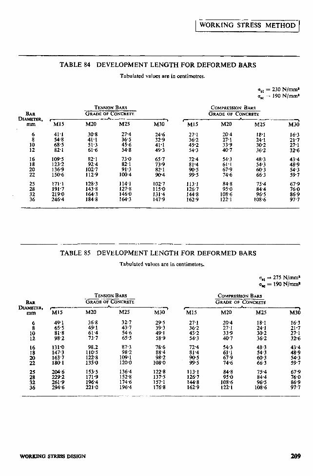
WORKING STRESS METHOD I
BAR DIAMETER,
mm
: 10 12
16 18
TABLE 84 DEVELOPMENT LENGTH FOR DEFORMED BARS
Tabulated values are in centimetres.
%t = 230 N/mm*
SC = 190 N/mm’
xi----- 41.1 54.8 68-5 82-l
109.5 123.2 136-9 150.6
171’1 191.7 219.0 2464
TENSION BARS GRADE OF CONCRETE
PA_ M20 M25
30.8 27-4 41.1 36.5 51.3 45.6 61.6 548
82-l 73.0 92.4 82.1
1027 91.3 1129 100.4
128.3 114.1 143.8 127.8 164.3 146.0 184.8 164.3
M30 ’ TiiY 24.6 27.1 329 36.2 41.1 45.2 49.3 ,54*3
65.7 73.9 82.1 90.4
724 81.4
z*:
1027 113.1 115*0 126.7 131.4 144.8 147.9 1629
COMPREWON BARS GRADE OF CONCRETE
M20 M25 M3d
20.4 18.1 16.3 27.1 24-l 21-7 33.9 302 27.1 40.7 36.2 32-6
54.3 48.3 43.4 61.1 54-3 48-9 67-9 EC: 54-3 74.6 597
84.8 75.4 67-9 95.0 84.4
108.6 96.5 L!&! 122.1 108.6 97.7
BAR DLAMEI-ER,
mm
16 18
;:
TABLE 85 DEVELOPMENT LENGTH FOR DEFORMED BARS
Tabulated values are in centimetres.
Qll = 275 N/mm* 0,=19ON/mm
TENSION BARS _.___.___ GRADE OF CONCRETE
,_-__h_ > Ml5 M20 M25 M30
49-l 36.8 327 29.5 :::; 491 61.4 43,7 54.6 49.1 39.3
98.2 73.7 65.5 58.9
131-o 98.2 87.3 78,6 147.3 ::I; 98.2 88.4 163.7 109*1 98.2 180.1 135.0 120.6 108.0
% f 153.5 171.9 136.4 152.8 1228
261.9 196.4 174.6 z: 2946 221.0 1964 176.8
27.1 36.2 45.2 54-3
72.4 81.4
E:
20.4 18.1 27.1 241 33.9 30.2 40.7 36.2
z: 48-3
67.9 z:: 74-6 66.3
43.4
E 597
113.1 848 75.4 67.9 126.7 95.0 84.4 76.0 144.8 108.6 96.5 86.9 162.9 1221 108.6 97.7
COMPRESSION BARS GRADE OF CONCRETE
\ M20 M25 M30
16.3 21.7 27-l 326
WORKXNQ STRBSS DESIGN 209

As in the Original Standard, this Page is Intentionally Left Blank


As in the Original Standard, this Page is Intentionally Left Blank
7. DEFLECTION CALCULATION
7.1 EFFECTIVE MOMENT OF INERTIA
A method of calculating the deflections is given in Appendix E of the Code. This method requires the use of an effective moment of inertia I& given by the following equation
I&r - Z* 1.2-s; 1-2 +_
( )
but, Ir < Za < b Whrn
Ir is the moment of inertia of the cracked section ;
fcllll Mr is the cracking moment, equal to -
where Yt
fa is the modulus of rupture of con- crete, Zm is the moment of inertia of the gross section neglecting the re- inforcement and yt is the distance from the centroidal axis of the gross section to the extreme fibre in tension ;
M is the maximum moment under service loads;
z is the lever arm; d is the effective depth; x is the depth of neutral axis; b, is the breadth of the web; and b is the breadth of the compression face.
The values of x and z are those obtained by elastic theory. Hence z = d - x/3 for rectangular sections; also b = b, for rec- tangular sections. For flanged sections where the flange is in compression, b will be equal to the flange width br. The value of z for flanged beams will depend on the tlange dimensions, but in order to simplify the calculations it is conservatively assumed the value of z for ganged beam is also d - x/3. With this assumption, the expression e&c- tive moment of inertia may be written as follows :
but, F > 1 r
and Zen< Zm Chorr 89 can be used for finding the value of
F in accordance with the above equation. I
The. chart takes into account the condition
4 > 1. After finding the value of Zd it has I
to be compared with Z* and the lower of the two values should be used for calcula- ting the deflection.
For continuous beams, a weighted average value of Z~lr should be used, as given in B-2.1 of the Code.
7.2 SHRINKAGE AND CREEP DEFLECTIONS
Deflections due to shrinkage and creep can be calculated in accordance with clauses B-3 and B-4 of the Code. This is illustrated in Example 12.
Example 12 Check for deflection Calculate the deflection of a cantilever
beam of the section designed in Example 3, with further data as given below:
Span of cantilever 4.0 m Re\didimoment at service 210 kN.m
Sixty percent of the above moment is due to rmanent
% loads, the loading being distri-
uted uniformly on the span.
BP ZE =-i-T= 12
300 x @O)* _ 5.4 x 10’ mm’
From clause 5.2.2 of the Code,
Flexural tensile strength,
fcr = 0.74 z N/mm9 fcr P O-7 t/E = 2.71 N/mm’
Yt -D/2=~=3OOmm
2.71 x 5.4 x 10’
- 488 x 10’ N.mm
- O-067
a’/d II 005 will be used in referring to Tables. From 5.2.3.Z of the Code, EC = 5700 q/fck N/mm*
I 5 700 d/13= 22-l x 10’ N/mm*
A?& P 200 kN/mm* = 2 x 10s N/mm%
DEFLECTION CALCULATION 213

From Example 3, p, = 1.117.p, =0.418 p,(m - I)/@, m) = (0.418 X 8.05)/
(1.117 X 9.05) = 0.333 PJ?? = 1.117 x 9.05 = 10.11 Referring to Table 87,
I,/(bd’/ 12) = 0.720 . . I, = 0.720 X 300 X (562.5)‘/ 12
= 3.204 X IO9 mm4 Referring to Table 91,
J = 0.338
Moment at service load, M = 210 kN.m = 21.0 X 10’ N.mm
Mr/ M = 4.88 X 10’ 21.0 x lo’= o.232
Referring to Chart 89. I,,,/ I, = 1.0
. Ierr = I, = 3.204 X IO9 mm’ For a cantilever with uniformly distributed load,
2
Elastic deflection = f .g cll
2 1 .o X 10’ x (4000)? z -__--- 4 x 22.1 X lo3 x 3.204 X 10”
= I I.86 mm . ..( 1)
Deflection due to shrinkage (see clause B-3 of the Code):
II Lo = k+ Vv, I‘
ki = 0.5 for cantilevers p, = l.l17,p, = 0.418
pi--p<= 1.117-0.418=0.699< 1.0
. . . ~4=0.72Xy& ’
Pt
= 0,72 x (1.1.17 - 0.418) fii-iT
== 0.476
In the absence of data, the value of the ultimate shrinkage strain &, is taken as 0.000 3 as given in 5.2.4.1 of the Code.
L)=6OOmm
’ Shrinkagecurvature q\Ir,, = k4 g . .
0.476 X 0.000 3 = = 600
2 38 x 1o-7
a,, = 0.5 X 2.38 X 10e7 X (4 000)2 = 1.90 mm . ..(2)
Deflection due to creep,
a,, (pcrm) = a,,, (p,r,nj - a, ,,,cmr, In the absence of data, the age at loading
is assumed to be 28 days and the value of creep coefficient, 8 is taken as 1.6 from 5.2.5.1 of the Code.
EC, = E, 1 +e
= 22.1 x IO3 = 1 + 1.6 8.5 X 10’ N/mm2
E, 2x IO5 m = z = 8.5 X lo3
= 23.53
p, = 1.117, pL = 0.418 pc (m - l)/(p,m) = 0.418(23.53 - I)/
(1.117 X 23.53) = 0.358
Referring to Table 87, t,/(bd’/ 12) = I,.497 I, = 1.497 X 300 (562.5)3/ 12
= 6.66 X lo9 mm” I, < Lrr d I$q 6.66)X 10” d I,,, < 5.4 x IO9 * Ierr = 5.4 X 10’ mm4 . .
alcc (,,rr,,r, = Initial plus creep deflection due to permanent loads obtained using the Above modulus of elasticity
1 Ml2 --- = 4 E&r
= $X (0.6 X 21 X 10’) (4 000)2
8.5 X IO3 X 5.4 X IO9 = 10.98 mm
a I (pwn\ = Short term deflection due to permanent load obtained using EC
1 (0.6 X 21 X 10’) (4 000)’ =i-x- 22.1 X 10’ X 3.204 X IO9 = 7.12 mm
. . . a‘r(pc.,m) = 10.98 - 7.12 = 3.86 . ..(3) Total deflection (long term) due to initial . . load, shrinkage and creep = 1 1.86 + 1.90 + 3.86 = 17.62 mm. According to 22.2(a) of the Code the final
deflection should not exceed span/2SO. .
Permlsslble deflection = 250 ‘&!I?!!? = 16 mm.
The calculated deflection is only slightly greater than the permissible value and hence the section may not be revised.
214 DESIGN AIDS FOR REINFORCED CONCRETE

i w t ii L
1.0
10
RATIO bf/bw
DEFLECTION CALCULATION 215
Chart 89 EFFECTIVE MOMENT OF INERTIA FOR CALCULATING DEFLECTION
f
i-
b-0 3i 1.0
1.1 L_;______;-__ _;-c_$ IY
I I I I I I hi-- I I I i I I I I I I
- 1
I I Al I I I %++-I I I “8 I
l-4
l-5
1.6
1.7
1.8
l-9
2~0"""""""'~""""""~
216 DESIGN AIDS FOR REINFORCED CONCRETE
Chart 90 PERCENTAGE, AREA AND SPACING ‘OF BARS IN SLABS
29
24
23
22
21
20
19
10
9
0 1 2 J b s 9 1 D 9 10 11 12 13 14 19
AREA OF REINFORCEMENT cm’ PER METER WIOTH
+USf ECfCCtlVL OCfTM OR OVERALL WHICHEVER IS USLO POR CALCUlATING p
DBFLECTION CALCULATION 217
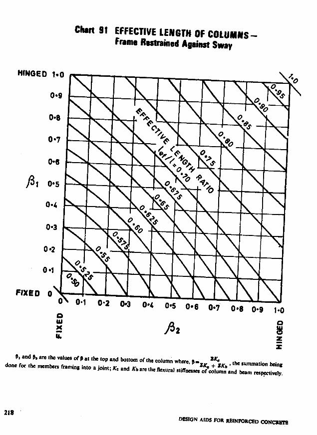
.
Chart 91 EFFECTIVE LEhlGlH OF COLUMNS- Frame Restrained Against Sway
FUED 0
0.6 0*7 0.8 0.9 l*O P
E ii P a 8
z r
BX and Pa are the values of 19 at the top and bottom of the column when, p- sKc
done for the members framin8 into r joint; KC and Kb arc the fkxural the summation being
stiffacoses r;K, + tKb ’ of column and &m mpiwfy.
218 DESk3N AIDS FOR REINFORCED CONCRHI
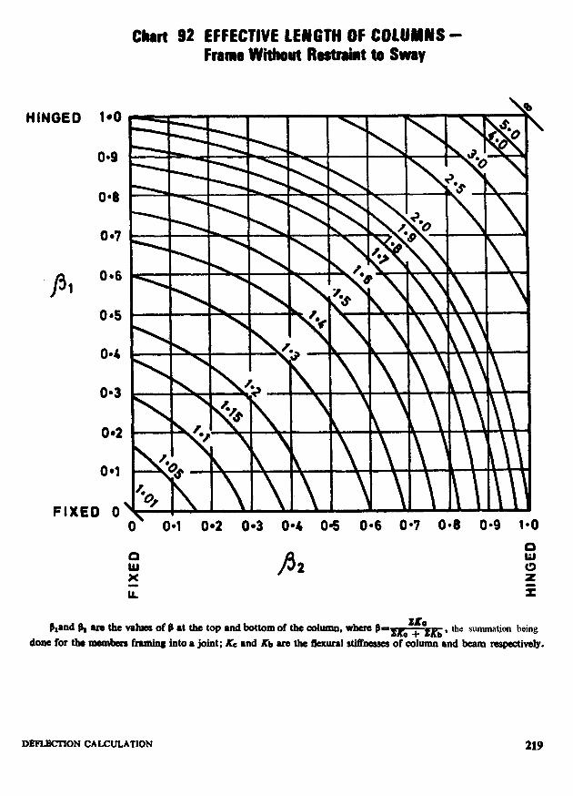
0*9
04
P 0.6 1
FIXED 0
chrrt 92 EFFECTIVE LENGTH OF COLUMNS - Frame Wiiut Restraint to Sway
o\ 0.1 0.2 0.3 04 03 0*6 0.7 0.8 0.9 1-O
wp x ii
P 2
hand @, are the values of b at the top and bottom of the column. where b’~Kc~sKb, tbe swnmation being
done for tbo mombem framing into a joint; KC and Kb are the llex~rd dfhessu of &Umn and beam respeCtivclY.
DFMACMON CALCULATION 219
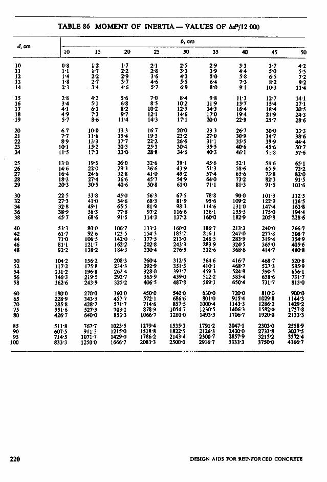
TABLE 86 MOMENT OF INERTIA- VALUES OF M/12 000
d. cm 15 20 25
b, cm
30 35 40 45 50
10
53-3 61.7
E 922
lW2 117-2 131.2 146-3 1626
180-O
%:X 351.6 4267
511.8 767.7 607-s 911’3 7145 1071.7 833.3 1250.0
1.2 l-7
$;
;;
;:; 46
10-O
:::4 15.2 17.3
19.5 220 24-6 27-4 30-5
33.8 45.0 41.0 546 49.1 65.5 58.3 77’8 68.6 91-5
it:
:z3 138-2
106-7 123.5 1420 1622 :843
:f:; 196.8 219-5 243-9
208-3 260-4 234.3 2929
i;::‘: ~%I: 325.2 406.5
270-O 343.3 428.7 527-3 640.0
360.0
::::7’ 703.1 853.3
1023.5
%X 1666-7
g:‘: 10-2 12-l 143
g
146 17-l
326 36-6 41-o 45-7 50-8
z:: 81.9 97.2
1143
67-5 81.9 98.3
fK4
::::: 177-5 202-8 23@4
3125 364.6 351.5 410-l 393.7 459-3 439-o 5122 487.8 569-l
450.0 5400 5721 686.6 7146 857.5 878.9 10547
1066-7 1280-O
1279-4 1518.8 1786-2 2083.3
z:: 2143.4 2500.0
1rt 14-3 17-O 20-O
23.3 27-o 31.1 35.5 40.3
45.6 51.3
z:t 71-l
78.8 95.6
114.6 136-l 160.0
186.7 216-l 248.5 283.9 322.6
630.0 801.0
fzz 1493’3
1791.2 2126-3
K::
::: 5-8
;:;
11.3
z 19-4 m9
52-l
:!:f 73-2 81.3
90.0 109.2 131.0
:z .
213.3
E8 324-5 368.6
416-7
iii:; 585-4 650-4
ES .
tz:: 1706-7
2047-l
ii% . 3333’3
::g 6-5
1::
:::: 18.4 21.9 25.7
58.6 65.9
i::!! 91.5
101.3 122.9 147-4 175.0 205.8
2400 277.8 3194 365.0 4147
E: 590-5 658.6 731.7
8AO.O 10298 1286-2 15820 192@0
4-2 5.5
;‘2 11.4
14-l 17-l
z 28.6
33.3 38-6
iii:: 57-6
65-l 73-2 82-O 91.5
101.6
1125
%5 . 194-4 228.6
266.7
:::I: 405-6 460-8
5208
i%; 731.7 813-O
1E
:%-ii 2133:3
%T . 3572’4 4166-7
220 DEMON AIDS FOR REINFORCED CONCRETE
TABLE 87 MOMENT OF INERTIA OF CRACKED SECTION -
VALUES OF &/(R”)
. 0-O
O-298
:::z 0398 O-430
iz
x’:;; .
O-601 O-628 @653 O-678 O-703
0.839 O-860 O-881
:zi
l-123 l-156 l-188 1.220 l-250
O-3
O-100
11::;1;: O-226 O-264
O-472
FiTi
O-596
O-625 O-654 O-682 O-710 0,738
0765 O-792 O-818 O-844 O-870
0.8
O-100
Ki 0229 0269
O-490 O-525 0.559
zi
8’:;; . O-723 O-755 O-787
O-818 0.850 0.880 O-911 0942
1.121 l-179
:-zz . l-351
;:g
l-575 l-630
l-685 l-739
::z 1902
1.6
0.310 O-348 O-386 O-424 0460
0.4% 0332 O-567
o”:zz
O-670 O-704 O-738 0.771 0.804
O-837
x:ii; 0.934 0.966
0998 l-030 l-061 1.093 l-124
1.155 l-217 I.278 l-340 1400
1461 l-521 l-581
::z l-758 l-817 l-876 1.934 1993
DEFLECTION CALCULATION 221

TABLE 88 MOMENT OF INERTIA OF CRACKED SECTION -
VALUES OF h,(z)
0.0
E! O-366 O-398 O-430
0.727
X:E O-795 O-818
O-839 O-860 0881
Ez
o-942 0.980 1.018
1:E
l-123 l-156 I*188
f:E
12$ 1.337
:::9”:
@l
E O-185 O-224 O-262
0.298 O-333 O-367
Et!
O-463 O-493 0523 O-551 O-580
O-607 O-634
;:z o-71 1
O-854 O-876 0.898
:E
0962
EZ l-082 1*120
1.157 1.193
::E! l-296
l-329
:::: 1.425 l-455
O-3
O-100 O-144 O-185 O-225 O-263
O-300 0.335 0.370 0403 O-436
0468 O-499 O-530 O-560 O-589
O-618
::zE O-701 O-727
0999 l-045
:d~ l-176
1.218 I.260 1301
::z:
04
&lOO 0.144 0.185 0225 O-263
O-300 @336 O-371 0405 O-438
0.470 O-502
8:::: O-593
0.622 o-651 0680 O-708 0735
8:::; O-815 O-841 0867
l-247 1.291
:::z I.419
1461
::E l-583 l-623
O-6 O-8
0.100 O-144 O-186 O-226 0264
O-100 O-144 Q186
::z
0.302 0338 O-373
zz
O-303 O-340 O-376 O-41 1 O-445
O-479 O-512
8:::: 0.609
O-632
z: O-720 0.749
I:E
8E l-022
O-792
z::
Ez .
:z: 0.993 l-021 lft49
l-077 1.103 l-131 1.160 l-185 l-217 l-239 1.274 1.292 I.330
l-298 1.347
::z l-489
l-344 1.3%
::g I.551
l-535 lTjO1 1582 1.652
t-E . :E l-718 1*801
1.0
F$$
0.413 O-448
0.483 o-517 0.550 0.583 O-616
O-648
::tE! 0.743 O-774
0.805 O-836 O-866
f:E
0956 O-986 l-015
fZ
1.386 1441
f :Zf I.606
222 DESIGN AIDS FOR RRINFORCED CONCRETE
TABLE 89 MOMENT OF INERTIA OF CRACKED SECTION -
VALUES OF It/ s t )
r
o-0 0.1
O-100 0.143 O-185
x:z
0.100 O-143 0.185 O-224 0.262
O-298
EZ O-398 0.430
O-298 O-333 0.367 O-399 0.43 1
x:z 0519 0547 O-575
O-462
X:iE 0.550 O-578
0.601 O-628 O-653 O-678 o-703
O-605 O-632 O-658 O-683 o-708
O-727 O-733 0750 0.757 0773 0.781 0.795 O-804 0.818 O-827
0.839 0.849 O-860 0871 O-881 0.893 0902 0914 O-922 O-935
O-942 O-980 l-018 l-054 1 a89
0956 0997 l-036 1.075 J-112
1.123 l-156 I.188 1.220 l-250
1.148 1.184 l-219 I *252 J-286
1.280 1.308 I.337 l-364 1.391
1.318 1.354 J-350 1.388 l-381 I.422 I-411 1455 1441 1488
O-2
O-100 O-143 O-185 O-224 O-262
O-298 O-333 O-367
z!
0.463 @494 O-523 O-552 O-581
O-608 O-635 0.662 O-688 0.714
O-739 O-764 O-788 O-812 @836
O-859 O-882
;z
0.970 I-012 I .054 I.094 I.134
I.172 l-210 1.247 I.283 I.319
0.3
@JO0 O-143 0.185 O-224 O-262
O-298 0334 O-368 0401 O-433
O-465 O-495 O-525 O-555 O-583
0.611 0639
8:E O-719
0,745 @770 O-795 0820 O-844
O-868 0.891 O-915 O-938 O-960
0.983 1.027 l-070 1.112 J-154
J-194 1234 I.274 1.312 1.350
1.387 J-424 J-461 1.4% 1.532
O-4 o-6
o-100 0.143 0.185 O-224 0262
O-100 @I43 0.185 OQ24 0.262
0.299 O-334 O-368 O-402 0,434
x:E O-369 0403 0.436
zz! 0.527 O-557 O-586
0468
Ei O-561 O-591
O-614 O-643 0.670 0.697 0724
0.620 O-649 0.678 O-706 O-733
O-750 0.776 O-802 0827 O-852
0,761 O-788 0814 O-841 0.867
O-876 O-893 0901 O-918 0.925 0943 0,949 O-969 0.972 0.993
E 1.086 l-130 1.173
:::t l-115 l-162 1 a208
I.216 I.257 I.299 l-339 1.379
1.419
: ::z: l-535 1.573
I.476
zzi l-605 1 a7
O-8
O-100 0.143
xi!: O-263
0.300
FL::: O-405 O-438
0.471 o-503 O-534 O-565 0.596
O-626 O-655 O-685 O-713 O-742
O-770 0.798 O-826 O-853 O-880
X:K 0.960 0.987 l-013
J-039 l-090 I.141 l-191 l-240
I:627 l-574
1E I.712
J-0
O*lOO 0.143
8‘::: . O-263
0473 O-505 O-537 O-569 O-600
O-631 0.661 O-691 O-721 O-750
O-779 P808 O-836
::8896:
0.92 I O-948 O-976 l-003 1 a30
l-057 1~111 1.164 1.216 l-268
I.320 1.371 I -422 I.473 I.523
1.573
‘I :x:3 I.721 1 a770
DEFLMXION CALCULATION 223

TABLE 90 MOMENT OF INERTIA OF CRACKED SECTION -
VALUES OF Jr/ $ ( )
Am--l)/(m)
d'/d-O-20
0-l O-2 0.3 O-4 O-6 O-8 19’
;;
O-399 O-430
O-298 O-333
!E!
O-298 O-333
EZ O-431
a298 O-333 @367
X%
0.298 O-333 O-367
%i .
Ei O-368 O-401 O-434
O-462 O-492
:::: O-579
8% 0.523 0.552 @580
yg
O-554 O-583
:%! 0528 O-558 @588
O-603
zz O-681 O-706
O-605 O-632 O-658
Ei
O-607 0.634
iT% 0.712
0o:g O-663 O-689 O-715
@614 O-643 O-671 O-699 O-726
@617
ic
O-731
O-730 0754
Ei Of23
O-734 O-758 0.782
EE
O-741 0.766 O-791 O-815 O-839
0.753 O-779 O-806 O-832 O-857
x’::: . O-812 0839 O-865
0.863 0.874 O-887 O-898 0910 O-922
z:: ii%
0.883
Ei @958 O-983
Ei 1931
:%i
o-961
:izz l-082 l-120
0969 l-012
:z!z l-135
O-978 l-022 la65
xi .
O-993 1 so39 l-085 l-129 l-173
l-007 1955 1.103
:z
ST% 1.119 l-168 1:216
1141 l-176
:-iii . l-276
l-174 l-212
:% . l-324
1.189
:zz 1.307 1.345
l-217 l-259
1:E l-384
1.308 l-339
:%i . l-429
l-334 1368
::zi 1464
l-383 1,420
:1E 1.528
1.425
::zz l-545 l-584
l-241 l-287 l-331
:*:z .
1463 l-506
:::;; l-633
Et 1358 1 a5 1.451
1.497 l-542 l-587 l-632 1.677
224 DESIGN AIDS FOR REINFORCED CONCRETE
TABLE 91 DEPTH OF NEUTRAL AXES - VALUES OF x/d BY ELASTIC THEORY
d’/d=@OS
O-132 O-159 O-181
EY
O-131 o-131 O-158 O-157 O-180 0.178 O-198 0.197 O-215 O-213
0.130 O-128 O-155 O-153 O-176 O-173 O-194 @190 O-209 0205
0227
E!i O-263 O-274
0225 O-238 O-249
z:
O-223 0235
i!Lg
0.218 O-214
tz! x:z O-251 O-245 O-260 O-253
0.287 @297
Ei O-323
EJ
0.305 O-312
0.276 O-284 O-292
Ez
O-268 0.276
;ij
0.261 0.269 0.276 0.282 0.289
O-336
8E O-358 O-365
0.330 O-338 0345 0.352 O-358
@325
E O-345 @351
0.319 O-314 0.304 O-326 0:321 O-310 O-333 O-327 O-316 O-339 O-333 O-321 O-345 O-339 C+326
O-294 O-300 O-305
:::::
@358 O-363 0.369 0374 O-380
0.351
EZ O-367 O-372
:::t ::E 0.341 0328 0.345 0332 O-350 0.336
MO2 Oar7 O-413 O-418 0,423
O-393 O-398 O-403
z!
O-385 O-390 O-394 O-399 O-404
EZ O-378 O-382 @386
O-418 O-427
E O-451
:iti 0.425 O-432 O-439
O-399
:zi O-421 0428
x- O-459 0465 0.471
O-383 @388 0392 O-396 0400
O-507 O-513 0519 O-525 O-531
O-491 0497 0503
8E
Ez 0488 O-493 0.498
::g O-411 0.414 O-417
DEFLECTlON CALCULAflON 225

TABLE 92 DEPTH OF NEUTRAL AXIS - VALUES OF x/d BY ELASTIC THEORY
01 0.2
0.132 0.131 @158 0.158 @MO 0.179 0.199 0.198 0.215 0.214
0230
odz 0.268 0.278
0228 0242 0254 0.265 0275
0285
ii .
0.319
0331 0.339
%: 0.359
0.327 0.334 0.341 0347 0.354
8% 0.371 0.377 0.382
0.394
x:z 0.410 0.414
0.419 0.428 0.437 0445 0.453
fii$
0481 0487
0.493
Ei
8%
0.387 0.392 0.397
;:z
0.411
00::;; 0.435 0442
0449 0456
E; 0.475
0.4 0.6 0.8 1.6
0.131 0.130 0.130 0.130 0.157 0.156 0.155 0.154 0.178 ml76 P175 0.174 0.196 0.194 0.192 0.190 0211 0209 0.206 0.204
0.225 0.238 0249 0.260 0.270
XE 0245 0.255 0.265
0.219 0.231 0241 0.251 0.260
0.279 0288
812Z 0.311
0.273 0.282 0289 0296 0303
0263 0.270
x:18’: 0289
0.318 0.325 0.331 0.337 0.343
0.310 0316 0322
“0::::
X:E 0.313 @318 0.323
0.295 0.300 0.305 0310 0.314
0.349 0.338 0.354 0.343 0.359 0.348 0.364 0.352 0.369 0.357
8%
::::: 0.345
x::::
“0:::: 0.335
0.361 0365
8% 0377
0.349 0.353 0.357 0.360 0.363
0.395 0403
X% 0.423
0.380 O-387 @394 0400 0406
0.367 0.373
8% 0.389
0354 0.360 O-365 0.370 0.375
0.411 0.416 0.421 0.426 0.431
226 DESIGN AIDS FOR REINFORCBD CONCRBTB
TABLE 93 DEPTH OF NEUTRAL AXIS - VALUES OF x/d BY ELASTIC THEORY
’ o-0 0.1 O-2 0.3 o-4 0.6 0.8 1-d
0.132 O-159 O-181 0.199 O-216
O-132 O-159
8’:: .
O-215
0.132 0.132 O-159 @159 O-180 @180 O-198 O-198 O-214 O-214
o-133 0.158
:::;Y 0.212
0.133 0.133 0.158 O-lS8 O-179 0.178 O-196 O-195 O-211 O-209
z-z 0:258 O-270 O-281
O-231 0.244 0.257 O-268 0.279
0229 O-228 O-242 OatI 0.254 0.252 O-265 0.263 O-275 O-273
0224 O-222 0.236 0.234 0.247 0.244 0.257 O-254 0266 0.262
O-292 0301 O-311
ii:::
O-289 O-287 0.285 0.282 O-299 O-296 0294 O-291 @308 0.305 @302 O-299 0.316 O-313 O-310 o-307 O-324 O-321 0.318 o-315
0.278 0.287 0.294
x:z
O-274 O-282 O-290 @297 0.303
0.270 O-278 O-285
8:ZE
O-336 0.332 O-329 O-325 0322 0.344 O-340 O-336 0.332 O-329 o-351 O-347 0.343 fF339 O-335 O-358 0.354 O-349 O-345 O-341 0.365 O-360 O-356 0.351 o-347
O-315 O-322 O-328
x::::
0309 O-315 O-321 O-326 O-332
O-304
8Z 0.320 O-324
0372 O-378 O-384 O-390 O-396
0.367 O-373 O-379 O-385 O-390
0.362 O-368 O-374 0.379 0.384
8:::: O-369 0.374 O-379
0.353 O-358 0.364 O-369 0.374
O-344 0.349
x::::: 0.364
0.336 0.329 O-341 O-333 O-346 O-338 0.350 O-342 O-354 O-345
0402 O-407 O-413 O-418 O-423
0.396 O-401 0406 0.411 O-416
0.390 O-395
:‘iz O-409
0384 0.378 O-368 O-358 0.389 0.383 O-372 0.362 O-393 O-387 0.376 O-366 0.398 0.392 O-380 O-369 0402 O-396 0.384 O-373
0.349 O-353 0.356
“o::zi
O-428 O-437
Et 0.463
O-420 0.429 0.438
iEi
0.413 O-422 O-430 0.438 O-445
O-407 O-415 O-422 O-430 O-437
OaO
8::; 0422 0.429
O-388 O-395 O-401 0.408 O-414
O-376 O-383
“0::;; O-un
O-366 O-372 0.377 O-382 O-387
0462 O-469 O-476 O-482 O-489
O-452 0.459 O-466
8:::;
O-444 O-450 0.456 O-462 O-468
0.435 O-441 O-447
::t::
0419 0405 0.425 O-410 0.430 0.415 O-435 O-419 O-440 O-423
ZE O-401 0405 O-408
0495 O-501 O-506 0.512 O-517
@484 0.489 0.494
x:z
0.473 0.478
X:E 0493
O-463 0468
::t:‘7 0.481
::I$ . 0.453 0.457 O-460
0.427 0.412 0431 O-415 O-435 0.419 0438 O-422 O-442 0.425
DEFLECTION CALCULATION 227

ptm
1.0 1.5
;:;
3-o
3.5
9:;
5.0 5.5
:I’:
3::
8-O
11-o 11’5
:I:; 13.0
13.5 140 14-5 15.0 15-5
16-o 17.0 18-o 19.0 20.0
21-O
3:*8 24-o 25-O
TABLE 94 DEPTH OF NEUTRAL AXIS - VALUES OF x/d BY ELASTIC THEORY
d'jd=0.20
PC@+-lMptm)
. 0.0 0.1 0.2 0.3 0.4 0.6 0.8 1.6
O-132 0.133 0.133 O-159 0.160 O-160 O-181 O-181 O-182 0.200 0.200 0.200 O-217 0.216 O-216
0134 O-135 0.135 O-160 0.161 O-161 O-182 0.182 0.182
8:% 8% ::z
0136 0162 O-183 0.200 0215
0.232 0246 0.258 O-270 0.281
O-231 O-231
8:;;; x:z 0.269 O-268 O-280 O-279
0.231 O-230 0230 0229 0228 0.244 O-243 0.242 O-241 0.240 0.256 @255 O-254 0.252 0.251 0.267 0.266 O-264 0.262 O-261 O-277 0.276 0.274 O-272 0.270
0.292 0.301 @311 0.319 O-328
0290 O-300 O-309
x::::
x:4:: O-307 0.315 0.323
0.287 0*29., 0305 0.313 O-321
0.286 0.295
ii:::: 0319
,0.283 0.291 0.300 0.307 0.314
0280
8:;;: 0303 0.310
O-278 0.286 0.293
~:~
0.336 O-333 O-331 O-328 0.326 0.321 0317 0.313 O-344 0.341 0.338 0.335 0.333 O-328 0.323 0.318 O-351 O-348 O-345 O-342 0339 O-334 0329 0.324 O-358 0.355 O-352 O-348 0.345 0.340 0.334 0.329 0365 0362 0.358 O-355 0.351 0.345 0.340 O-334
O-368 o-364 O-374 O-370 0.380 0.376 0.386 O-382 0.391 0387
0.357 0.363 O-368
:%I
0.351 0356 0361 0.366 O-370
0.339 O-343 0.348 0352 0.356
8% O-413 O-418 0.423
0.397 O-392 0388 O-402 0.397 0.392 0407 0402 0.397 O-412 0407 O-402 O-417 0.411 O-406
O-383
8% 0397 0401
0375 0.379
k% 0391
8% 0.375 0.379 O-382
0.360 0364
::z: O-374
o-428 0.437 0446
t%:
8% 0.439 O-448 O-456
0.416 O-410 0405 O-425 O-419 0.413 0.433 0.427 f-b.421 O-441 O-434 0.428 O-448 0441 0434
O-395 0402
%z O-422
O-386 0377 0.393 0384 O-399 0.389 0405 0.395 0410 0400
0471 0.479 O-486 @493 O-500
O-455 0462 0.469 O-475 0.481
0448 O-454 0461
:z:
0441 0447 O-453 0.459 O-464
O-428 O-416 a433 0.421 0.439 O-426
:zi x:1:‘:
O-405
8:Z O-418 O-422
@478 0.483 O-488
tz;ii
0469
X% O-484 0488
0.453 0.439 @458 O-443 @462 O-447 0.466 O-450 O-470 0.454
0426 O-429 @433
x:1:9”
228 DESlGN AIDS FOR REINFORCED CONCRET’E
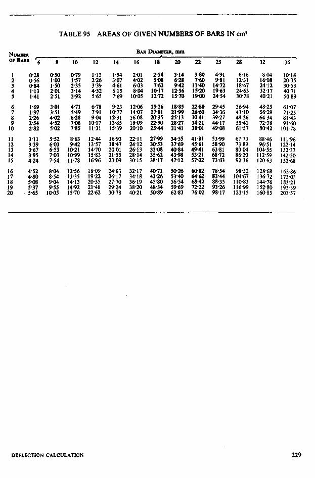
TABLE 95 AREAS OF GIVEN NUMBERS OF BARS IN Cm)
NUMBER BAR DIANKIER. mm
OPBAW - ,
6 28 32 36 10 12 14 16 18 20 22 25
::i; 2.26 1.13 3.07 I -54 2o1 4.02 z 3.14 3.80 . 491
235 339 461 6.03 763 i% 1% l:% :z: 452 5.65 6.15 769 10.05 8.04 10.17 12.72 1256 15.70 15.20 1900 2454 1963
6.16 8 01 IO.18 1231 1608 2035 18.47 24.12 30.53 2463 32.17 40.71 30.78 40.21 50.89
5.65 10.05
8.63 1244 1693 211 2799 9.42 13.57 18.47 24.12 30.53
10.21 1470 20.01 26.13 33.08 1099 15.83 21.55 28.14 35.62 11.78 16.96 23.09 30.15 38.17
1:::: 1413 1492 15.70
6.78 923 12% 15.26 7.91 10.77 14.07 17.81 9.04 1231 l&O8 20.35
10.17 13.85 18.09 2290 11.31 15.39 20.10 2544
18.09 24.63 3217 40.71 i9*i2
-. __ 2617 3i*iS 43.26
20.35 27.70 36.19 45.80 21.48 2924 38.20 48.34 22.62 30.78 40.21 50.89
l&85 2199 25.13
iK
34.55 37.69
z% 47.12
50% 53.40 56.54 5969 6283
22.80 29.45
zz ii::; 34.21 44.17 38.01 49.08
41.81 5399 45.61 5890 4941 63.81 :;g . g*;;
z% ix 68.42 88.35 ;;g ;;g
36.94 48.25 61.07 43.10 56.29 71.25 49.26 6434 81.43 55.41 7238 91 a 61.57 80.42 101.78
67.73 73.89 80.04 86.20 92.36
88.46 96.5 I
101.55
: g:;;
111.96 122.14 132.32 142.50 152.68
98.52 128.68 104.67 136.72 1 IO.83 144.76 116.99 152.80 123.15 160.85
162.86
f ;;:;;
193.39 203.57
DEFLECTION CALCULATlON 229
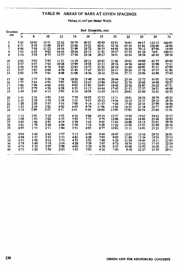
TABLE 96 AREAS OF BARS AT GIVEN SPACINGS
Values in cm2 per Meter Width
cm 6 8 10
5.65 471
% 3.14
10.05 15.71 8.38 13.09 7-18 11-22 6.28 9.82 5.58 8.73
10
t:.
::
2.83 257
z7” 2.02
5.03 7.85 4.57 7.14 4.19 6.54
ZJ 4::
15 1.88 3.35 5.24 16 l-77 3.14 4.91 17 l-66 2.96 4-62 18 1.57 2.79 4.36 19 1.49 2.65 4.13
1.41 2.51 3.93 1.35 239 3-74 l-28 2-28 3.57 1.23 218 3’41 1.18 2-09 3.27
l-13 2.01 1.09 1.93 l-05 1.86 1 *Ol 1.79 0.97 1.73
3.14
;:Ff 2.80 271
30 32 34 36
::
O-94 0.88 0.83 0.78 0.74 071
1.68 1.57 1.48
:z 1.26
2.62 245 2.31 2.18 2.07 1.96
BAR DIAMEIER. mm 1
12 14
22.62 30-79 18.85 25.66 16.16 2199 14-14 19-24 12-57 17.10
11.31 ::-sz 10’28 *
9.42 1283 a.70 11.84 S-08 11-00
% 10.26 9-62
f:E 9.05 8-55
5.95 8.10
5.65 7.70 5.39 7.33 5-14 4-92 ::z! 4’71 6.41
4.52 6.16 4.35 5.92 419 5-70 4.04 5.50 3-90 5-31
3.77 5.13 3-53 4.81 3.33 4.53 3.14 4,28 2.98 4.05 2.83 3.85
16 18
40-21 33.51
f E 22.34
50.89 4241 36.35 31.81 28.27
20-11 25.45 18.28 23.13 1675 21.21 15.47 19-57 1436 18.18
1340 1696 1257 15?w 11-83 14-97 11.17 1444 IO-58 13.39
10.05 12.72 9-57 12.12 9.14 11.57 8.74 11.06 8.38 10-60
8.04 7-73 7.45 7.18 6-93
6-70 8.48 6-28 7.95 5.91 7.48 5.58 7.07 5.29 6.70 5.03 6.36
20 22
6283 76.03 52.36 63.36 44.88 54.30 39.27 47.52 3491 4224
31.42 38.01 28.56 34.56 26.18 31.68 24.17 29.24 22.44 27.15
20.94 25.34 19.63 23.76 18.48 22.36 17.45 21.12 16.53 20-01
15.71 19.01 14.96 18.10 4.28 17.28
13’66 16-53 13.09 15.84
12.57 15.20 1208 14.62 11.64 1408 1 l-22 13.58 10.83 13.11
10-47 12.67 9-82 11.88 5.24 11-18 8.73 10-56 8.27
‘!?z 7.85 .
25 28 32 .
98.17 123’15 81.81 102%8 70.12 87.96 61.36 76-9 54-54 68’42
16085
:4qs 10053 89-36
49-09 61.57 80-42 44.62 55.98 73.11 40-91 51-31 6702 37.76 47-37 61.86 35.06 43.98 57.45
:z 28.87 27.27 25.84
41.05 53.62 38.48 50-27 36.22 47.3 1 2421 44.68 32-41 42.33
24.54 30-79 40.21 23.37 29.32 3830 22.31 2799 36-56 21.34 26.77 34.97 20.54 25.66 33.51
19.63 18.88 18.18 17.53 16-93
24.63
f E 21.99 21.23
g:;;
29.79 28.76 27.73
16.36 20.52 26.81 15.34 19.24 25.13 14.44 18.11 23.65 13.63 17.10 22.34 12.92 16.20 21.16 12.27 15.39 20.11
230 DESICSN AIDS FOR REINFORCED CONCRETE
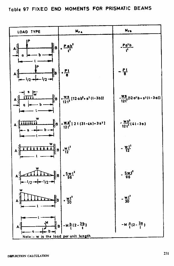
Table 97 FIXED END MOMENTS FOR PRISMATIC BEAMS
LOAD TYPE
W
A
t-----‘----l
M rr
Pab’
(’
PI I-
%
w, [’
12 1’
-7 121’
w I’ +12
12 ad+ s2 (I-3b)l
2 I (31~e4+3s’)
WI’
+20
Mm
Pdb
1’
‘,f+-3S)
w I2 -12
5Wl’
-96
w I2
-30
IXSf’LECT’ION CALCULATION 231
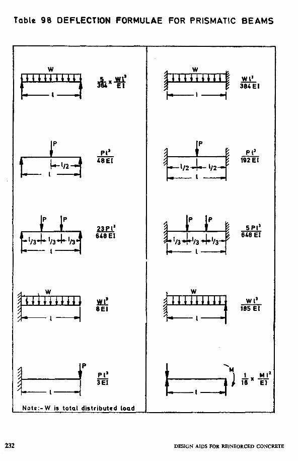
Table 98 DEFLECTION FORMULAE FOR PRISMATIC BEAMS
P
&it I+ ‘/2 I
L&! L ( w , ,’
rrrrcrrl , , , P 1 --I
Pl’ 48EI
23PI’ 6=
H!t 6E1
P 1’ 3
Note:- W is total distributed load
P 1’ 192
5 PI’ 646 EI
2 L,MI 16 EI
DESIGN AIDS FOR REINEORCED CONCRETE
Top Related