


Languages
Pages
Legal

22002224REV 0 REV 0
SmartClassTM Fiber FBP-HD4i/HD4iP and OLP-82/82P
USER MANUAL
Inspect, test, certify, and save with one device

USER MANUAL2
Notice Every effort was made to ensure that the information in this document was accurate at the time of printing. However, information is subject to change without notice, and JDSU reserves the right to provide an addendum to this document with information not available at the time that this document was created.
Copyright © Copyright 2012 JDSU, LLC. All rights reserved. JDSU, Enabling Broadband and Optical Innovation, and its logo are trademarks of JDSU, LLC. All other trademarks and registered trademarks are the property of their respective owners. No part of this guide may be reproduced or transmitted electronically or otherwise without written permission of the publisher.
Trademarks JDSU is a trademark of JDSU in the United States and other countries.
FCC Information Electronic test equipment is exempt from Part 15 compliance (FCC) in the United States.
European Union Electronic test equipment is subject to the EMC Directive in the European Union. The EN61326 standard prescribes both emission and immunity requirements for laboratory, measurement, and control equipment. This unit has been tested and found to comply with the limits for a Class A digital device.
Independent Laboratory Testing
This unit has undergone extensive testing according to the European Union Directive and Standards.

SmartClass™ Fiber FBP-HD4i/HD4iP and OLP-82/82P 3
CHAPTER 1 INTRODUCTION ......................................................................................................................... 6–7
SmartClass Fiber Devices ..................................................................................................... 6 Key Features and Functions ................................................................................................ 7
TABLE OF CONTENTS
CHAPTER 2 SAFETY INFORMATION .......................................................................................................... 8–9
Proper Usage ............................................................................................................................ 8 Battery Information ............................................................................................................... 8 Ventilation ................................................................................................................................. 9 PS4 Universal AC/DC Power Supply ................................................................................. 9
CHAPTER 3 GETTING STARTED .............................................................................................................. 10–16
Unpacking the Instrument ................................................................................................10 Packing Material .........................................................................................................10 Standalone Units.............................................................................................10 Additional Items in Basic Kits .....................................................................11 Additional Items in Pro Kits .........................................................................11 Controls ....................................................................................................................................12 Power Supply .........................................................................................................................13 Battery Operation .................................................................................................................13 Replacing AA Batteries ............................................................................................13 Recharging the Batteries.........................................................................................14 Using or Replacing the RBP2 Li-ION Battery Pack ..........................................14 General Tips on Using Batteries.......................................................................................15 Other Basic Safety Precautions ........................................................................................15 Environmental Protection .................................................................................................15 Operation from AC Power .................................................................................................16

USER MANUAL4
CHAPTER 5 INSPECTION ............................................................................................................................ 32–38
Hardware Overview .............................................................................................................32 P5000i Digital Probe ............................................................................................................32 P5000i Activation .......................................................................................................33 Integrated Patch Cord Microscope (PCM) ...................................................................34 PCM Activation ...........................................................................................................35 Inspection Menu ...................................................................................................................35 Brightness ...............................................................................................................................36 Profile ........................................................................................................................................36 Test .............................................................................................................................................37 Tip / Adapter ..........................................................................................................................38 Freeze ........................................................................................................................................38 More... .......................................................................................................................................38
CHAPTER 4 DEVICE SETUP AND CONTROLS ................................................................................... 18–31
Operator Control Panel ......................................................................................................18 Input Select Key (ISK) ..........................................................................................................19 Home Screen Display ..........................................................................................................20 Navigating in the Menus ...................................................................................................21 Home Screen Menu .............................................................................................................22 Recall Image ...........................................................................................................................23 Review OPM Data .................................................................................................................25 System Settings .....................................................................................................................26 Brightness ...............................................................................................................................27 Set Date ....................................................................................................................................27 Set Time....................................................................................................................................28 Auto Off Settings ..................................................................................................................29 Time Format ...........................................................................................................................29 System Information .............................................................................................................29 User Information ...................................................................................................................30 PC Connect .............................................................................................................................31
Table of Contents

SmartClass™ Fiber FBP-HD4i/HD4iP and OLP-82/82P 5
CHAPTER 6 OPTICAL POWER MEASUREMENT .............................................................................. 42–47
Power Meter Controls .........................................................................................................43 dB / dBm .......................................................................................................................43 SET REF ..........................................................................................................................44 λ (WAVELENGTH) .......................................................................................................44 MORE... ...........................................................................................................................44 Measuring Optical Power ..................................................................................................47 Measuring Absolute Power ....................................................................................47 Measuring Attenuation (Relative Power) ..........................................................48
SPECIFICATIONS ...........................................................................................................................49
ORDERING INFORMATION ......................................................................................................50
Table of Contents

USER MANUAL6
INTRODUCTION
1JDSU’s SmartClass Fiber family is the next generation of optical handheld test solutions that allow technicians to inspect, test, certify, and save on a single device. Designed to help users work smarter and faster, the SmartClass Fiber family incorporates the features that technicians rely on every day to deliver best-in-class reliable networks to their customers.
Products in the SmartClass Fiber family include:
CHAPTER 1 SmartClass™ Fiber FBP-HD4i/HD4iP and OLP-82/82P
HD4iDigital handheld video display
OLP-82Digital handheld video display with optical power meter
OLP-87Digital handheld video display with PON power meter

SmartClass™ Fiber FBP-HD4i/HD4iP and OLP-82/82P 7
Description HD4i OLP-82 OLP-87
Portable handheld display with 3.5" color touch screen
Simple graphical menu-driven interface
Accepts PASS/FAIL P5000i Probe
Accepts external USB power meter
Integrated connector certification reporting
On-board storage: Endface images and inspection analysis
User-definable acceptance criteria
Integrated optical power meter
On-board storage: Power meter results
Integrated PON power meter (BPON, EPON, and GPON)
Integrated PASS/FAIL patch cord microscope option HD4iP
OLP-82P
OLP-87P
Introduction CHAPTER 1
This User Manual will focus on the HD4i and OLP-82 products.
For further information on the OLP-87 or other JDSU fiber test tools, visit www.jdsu.com/test.
Key Features and Functions

USER MANUAL8
CHAPTER 2 SmartClass™ Fiber FBP-HD4i/HD4iP and OLP-82/82P
SAFETY INFORMATION
2Proper Usage
This instrument is intended for measurements on optical fiber devices and systems. Please make sure the instrument is not operated outside the permitted ambient conditions. Always make sure that the instrument is in proper working order before switching it on.
! Never short-circuit the battery contacts by touching both contacts simultaneously with an electrical conducting object.
! Only use AA size dry batteries or rechargeable batteries.
! Make sure the batteries are inserted with the correct polarity.
Battery Information
Explosion DangerShort-circuiting the batteries can result in overheating, explosion or ignition of the batteries and their surroundings.
Li-ION Battery CautionThe Li-ION Battery used in this device may present a risk of fire or chemical burn if mistreated. Do not disassemble, heat above 65°C or incinerate. Replace battery with manufacturer specified battery only. Use of another battery may present a risk of fire or explosion. Dispose of used battery promptly.
SmartClass™ Fiber FBP-HD4i/HD4iP and OLP-82/82P 9
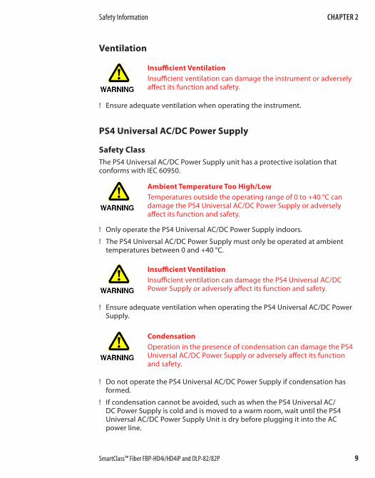
! Ensure adequate ventilation when operating the instrument.
Safety ClassThe PS4 Universal AC/DC Power Supply unit has a protective isolation that conforms with IEC 60950.
! Only operate the PS4 Universal AC/DC Power Supply indoors.
! The PS4 Universal AC/DC Power Supply must only be operated at ambient temperatures between 0 and +40 °C.
! Ensure adequate ventilation when operating the PS4 Universal AC/DC Power Supply.
! Do not operate the PS4 Universal AC/DC Power Supply if condensation has formed.
! If condensation cannot be avoided, such as when the PS4 Universal AC/DC Power Supply is cold and is moved to a warm room, wait until the PS4 Universal AC/DC Power Supply Unit is dry before plugging it into the AC power line.
Ventilation
PS4 Universal AC/DC Power Supply
Insufficient VentilationInsufficient ventilation can damage the instrument or adversely affect its function and safety.
Ambient Temperature Too High/LowTemperatures outside the operating range of 0 to +40 °C can damage the PS4 Universal AC/DC Power Supply or adversely affect its function and safety.
Insufficient VentilationInsufficient ventilation can damage the PS4 Universal AC/DC Power Supply or adversely affect its function and safety.
CondensationOperation in the presence of condensation can damage the PS4 Universal AC/DC Power Supply or adversely affect its function and safety.
Safety Information CHAPTER 2

USER MANUAL10
CHAPTER 3 SmartClass™ Fiber FBP-HD4i/HD4iP and OLP-82/82P
GETTING STARTED
3Unpacking the Instrument
Packing Material
We suggest that you keep the original packing material. It is designed for reuse. Using the original packing material ensures that the instrument is properly protected during shipping.
Checking the Package Contents
The following items will be included with each SmartClass Fiber instrument. Kitted packages contain additional items.
NOTE: For customer specific kits, the contents may vary according to specified configurations.
Standalone Units
• SmartClass Fiber Instrument
• Soft Bag for SmartClass Fiber and Accessories
• FiberChekPRO Software Installation Disk
• USB Cable USB-A to Micro-USB
• Quick Start Guide and Safety Instructions
• Dry Batteries (8X AA)

SmartClass™ Fiber FBP-HD4i/HD4iP and OLP-82/82P 11
Getting Started CHAPTER 3
Additional Items in Basic Kits
• P5000i Digital Inspection Microscope
• Inspection Tips and Adapters (Bulkhead: SC and LC; Patch Cord: 2.5 and 1.25 mm)
• 1.25 mm OPM Adapter (OLP-82/82P only)
Additional Items in Pro Kits
• P5000i Digital Inspection Microscope
• Inspection Tips and Adapters (Bulkhead: SC and LC; Patch Cord: 2.5 and 1.25 mm)
• 1.25 mm OPM Adapter (OLP-82/82P only)
• Cleaning Materials for 2.5 and 1.25 mm (Bulkhead and Patch Cord)
• FFL-050 Visual Fault Locator with 2.5 and 1.25 mm Adapter
• Hands-Free Carrier for SmartClass Fiber
• Rechargeable Battery for SmartClass Fiber (Li-ION)
• PS4 Power Supply for SmartClass Fiber (12V)

USER MANUAL12
CHAPTER 3 SmartClass™ Fiber FBP-HD4i/HD4iP and OLP-82/82P
Standard with Patch Cord Microscope (PCM)
uy
v
z
{
w
|
x}
~
Controls
u Connector interface (OLP-82/82P only)
v 3.5 inch color touch screen
w Key pad (operator control panel)
x LED indicators
y Patch Cord Microscope (PCM) with FMAE adapter (HD4iP and OLP-82P only)
z Test head cover (OLP-82/82P only)
{ Battery life indicator
| Graphic menu interface
} 2x USB2 interfaces, 1x micro-USB interface, external power supply connector
~ PCM controls (focus control, automated PASS/FAIL analysis, magnification control)
SmartClass™ Fiber FBP-HD4i/HD4iP and OLP-82/82P 13
Getting Started CHAPTER 3
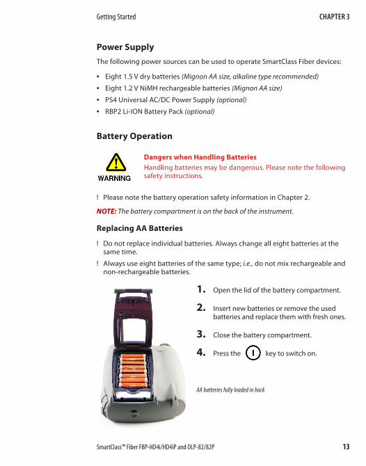
Power SupplyThe following power sources can be used to operate SmartClass Fiber devices:
• Eight 1.5 V dry batteries (Mignon AA size, alkaline type recommended)
• Eight 1.2 V NiMH rechargeable batteries (Mignon AA size)
• PS4 Universal AC/DC Power Supply (optional)
• RBP2 Li-ION Battery Pack (optional)
Battery Operation
! Please note the battery operation safety information in Chapter 2.
NOTE: The battery compartment is on the back of the instrument.
Replacing AA Batteries
! Do not replace individual batteries. Always change all eight batteries at the same time.
! Always use eight batteries of the same type; i.e., do not mix rechargeable and non-rechargeable batteries.
1. Open the lid of the battery compartment.
2. Insert new batteries or remove the used batteries and replace them with fresh ones.
3. Close the battery compartment.
4. Press the key to switch on.
Dangers when Handling BatteriesHandling batteries may be dangerous. Please note the following safety instructions.
AA batteries fully loaded in back
USER MANUAL14
CHAPTER 3 SmartClass™ Fiber FBP-HD4i/HD4iP and OLP-82/82P
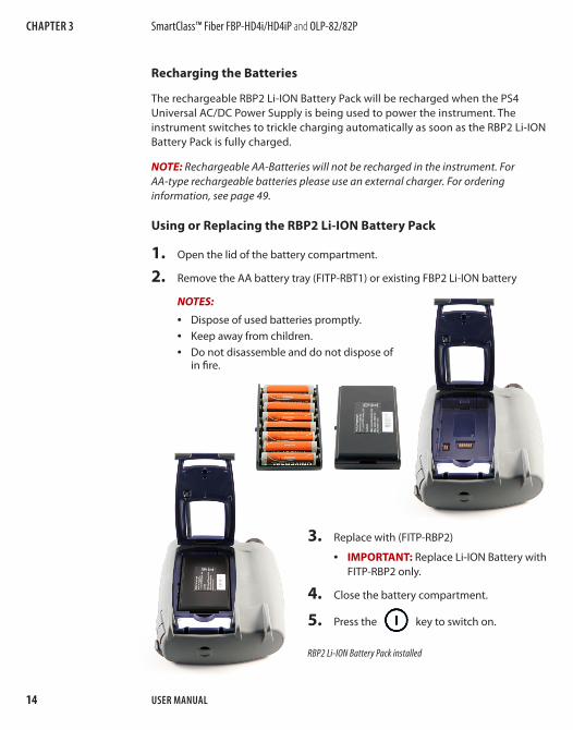
Recharging the Batteries
The rechargeable RBP2 Li-ION Battery Pack will be recharged when the PS4 Universal AC/DC Power Supply is being used to power the instrument. The instrument switches to trickle charging automatically as soon as the RBP2 Li-ION Battery Pack is fully charged.
NOTE: Rechargeable AA-Batteries will not be recharged in the instrument. For AA-type rechargeable batteries please use an external charger. For ordering information, see page 49.
Using or Replacing the RBP2 Li-ION Battery Pack
1. Open the lid of the battery compartment.
2. Remove the AA battery tray (FITP-RBT1) or existing FBP2 Li-ION battery
NOTES:
• Dispose of used batteries promptly. • Keep away from children. • Do not disassemble and do not dispose of
in fire.
3. Replace with (FITP-RBP2)
• IMPORTANT: Replace Li-ION Battery with FITP-RBP2 only.
4. Close the battery compartment.
5. Press the key to switch on.
RBP2 Li-ION Battery Pack installed

SmartClass™ Fiber FBP-HD4i/HD4iP and OLP-82/82P 15
Getting Started CHAPTER 3
General Tips on Using Batteries
• Always handle batteries with care.
• Do not drop or damage the batteries or expose them to excessively high temperatures.
• Do not store the batteries for more than one or two days at very high temperatures (e.g., in a vehicle), either separately or fitted in the instrument.
• Do not leave discharged batteries in the instrument for a long time if it is not being used.
• Dispose of used batteries promptly.
• Keep away from children.
• Do not disassemble and do not dispose of in fire.
Other Basic Safety Precautions
• Do not use PS4 Universal AC/DC Power Supply outdoors or in wet or damp locations.
• Connect the PS4 Universal AC/DC Power Supply to the correct mains voltage, as indicated on the ratings label.
• Do not allow anything to rest on the power cord, and do not locate the product where people can walk on the power cord.
• Avoid using this product during electrical storms. There may be a remote risk of electric shock from lightning.
• Do not use this product in the vicinity of a gas leak or in any explosive environment.
• Do not attempt to service this product yourself, as opening or removing covers may expose you to dangerous, high voltage points and other hazards.
• Contact qualified service personnel for all service and repair.
Environmental Protection
Please dispose of any unwanted dry batteries and rechargeable batteries carefully. They should also be removed from the instrument if it is to be scrapped. If facilities in your country exist for collecting such waste or for recycling, please make use of these rather than throwing the batteries in with normal trash. You will often be able to return used batteries to the place where you purchase new ones. Any dry or rechargeable batteries that you purchased from JDSU can be returned to one of our Service Centers for disposal.

USER MANUAL16
CHAPTER 3 SmartClass™ Fiber FBP-HD4i/HD4iP and OLP-82/82P
Operation from AC Power
NOTE: Only the PS4 Universal AC/DC Power Supply may be used to operate the SmartClass Fiber device from AC power.
To fit the AC line plug adapter:
1. Select the appropriate AC line plug adapter.
2. Slide the AC line plug adapter into the slot.
To change the AC line plug adapter:
1. Squeeze both sides of the PS4 latch lock.
2. Push the AC line plug adapter upwards.
3. Slide a different AC line plug adapter into the slot.
PS4 Universal AC/DC Power Supply is ready for use

SmartClass™ Fiber FBP-HD4i/HD4iP and OLP-82/82P 17
To operate the SmartClass Fiber device from AC power:
1. Connect the PS4 DC power cord to the DC power socket on the device. (The socket is under the cover on the right side.)
2. Plug the PS4 into the AC line socket.
NOTE: The PS4 provides power even if dry or rechargeable batteries are fitted in the instrument.
Getting Started CHAPTER 3

USER MANUAL18
CHAPTER 4 SmartClass™ Fiber FBP-HD4i/HD4iP and OLP-82/82P
DEVICE SETUP AND CONTROLS
4Operator Control Panel
HOME - Press to go to the home screen
MENU - Press to open a menu
BACK - Press to go back one step
INPUT SELECT KEY (ISK) - Press for fast toggling between device functions
* See page 19 for more information on using the ISK.
POWER - Press to switch the instrument ON and OFFNOTE: LED glows GREEN when the instrument is ON.
ARROW KEYS • Press to navigate through the menus • Press to change values in the menus
CENTER KEY • Press to confirm the selection
SAVE - Press to save results
LOW BATTERY - Glows RED when battery is low
TEST IN PROCESS - Glows RED when a measurement is running in the background
CHARGE - Glows AMBER when battery is charging; If the power is OFF, charging will continue with no LED indicator

SmartClass™ Fiber FBP-HD4i/HD4iP and OLP-82/82P 19
Input Select Key (ISK)
The Input Select Key allows users to inspect, test, certify, and save results quickly on the Smart Class Fiber device. Using this feature drives the user’s behavior by incrementally stepping them through each application as it should be used in a proper testing workflow. Pressing the ISK will immediately switch to the next application that is used in a typical workflow. Once pressed, a small icon will appear on the screen for a few seconds to indicate the application that is now active.
1. Press from the Home Screen Æ switches to PCM Inspection (or the next available application)
2. Press from an active application Æ switches to the next available application as follows*:
PCM Inspection Æ Probe Inspection Æ USB OPM Æ On-board OPM
NOTES:
* Each application will only appear if it is available on the device, either on-board or via USB connection.
Device Setup and Controls CHAPTER 4
USER MANUAL20
CHAPTER 4 SmartClass™ Fiber FBP-HD4i/HD4iP & OLP-82/82P
Home Screen Display
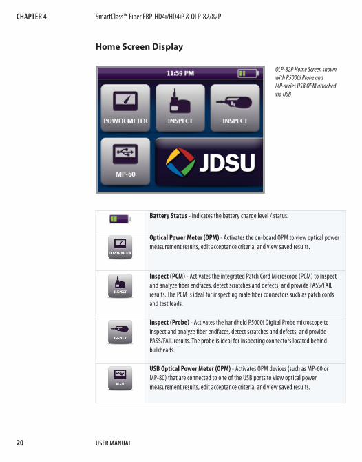
OLP-82P Home Screen shown with P5000i Probe and MP-series USB OPM attached via USB
Battery Status - Indicates the battery charge level / status.
Optical Power Meter (OPM) - Activates the on-board OPM to view optical power measurement results, edit acceptance criteria, and view saved results.
Inspect (PCM) - Activates the integrated Patch Cord Microscope (PCM) to inspect and analyze fiber endfaces, detect scratches and defects, and provide PASS/FAIL results. The PCM is ideal for inspecting male fiber connectors such as patch cords and test leads.
Inspect (Probe) - Activates the handheld P5000i Digital Probe microscope to inspect and analyze fiber endfaces, detect scratches and defects, and provide PASS/FAIL results. The probe is ideal for inspecting connectors located behind bulkheads.
USB Optical Power Meter (OPM) - Activates OPM devices (such as MP-60 or MP-80) that are connected to one of the USB ports to view optical power measurement results, edit acceptance criteria, and view saved results.

SmartClass™ Fiber FBP-HD4i/HD4iP and OLP-82/82P 21
Device Setup and Controls CHAPTER 4
Navigating in the Menus
Press the MENU key to open the context-sensitive menu.
Depending on which application is in the foreground, a different menu opens.
To select a menu item:
1. Press the ARROW KEYS to highlight an item.
2. To confirm, press the CENTER KEY within the arrow keys, OR
press the desired button on the touch screen.
To leave a menu:
• Press the BACK key.
NOTE: Actions can be operated via the operator control panel or the touchscreen. The following instructions describe only touchscreen operation.

USER MANUAL22
CHAPTER 4 SmartClass™ Fiber FBP-HD4i/HD4iP & OLP-82/82P
Home Screen Menu
BRIGHTNESS - Adjusts the brightness of the display
MORE... - Access additional features and functions universal to the device:
• RECALL IMAGE• REVIEW OPM DATA• SYSTEM SETTINGS• USER INFO• PC CONNECT
BRIGHTNESS
Adjusts the brightness of the display.
Once the BRIGHTNESS button is selected:
1. Press the left (darker) or right (brighter) ARROW KEYS to adjust the
brightness level.
2. Press the CENTER KEY to confirm your selected brightness level
- OR use the touch screen as follows:
• Tapthedesiredarrowbuttonstoadjustthebrightnesslevel • TaptheOKbuttontoconfirmyourselectedbrightnesslevel

SmartClass™ Fiber FBP-HD4i/HD4iP and OLP-82/82P 23
Device Setup and Controls CHAPTER 4
Recall Image
Opens list of fiber images saved on the device. Select one or multiple saved fiber images to view further details including analysis results.
Once RECALL IMAGE is selected:
• Press the up and down ARROW KEYS to browse through the list of
saved images
• Press the CENTER KEY to select one or multiple saved fiber images
• Press the MENU key to select any of the following:
- SELECT ALL: Selects all saved fiber images. When selected, a check indicator will appear in the selection box to the left of the image name.
- CLEAR ALL: Clears all check indicators in the selection boxes.
- DELETE: Deletes any items with a check indicator in the selection box.
USER MANUAL24
CHAPTER 4 SmartClass™ Fiber FBP-HD4i/HD4iP & OLP-82/82P
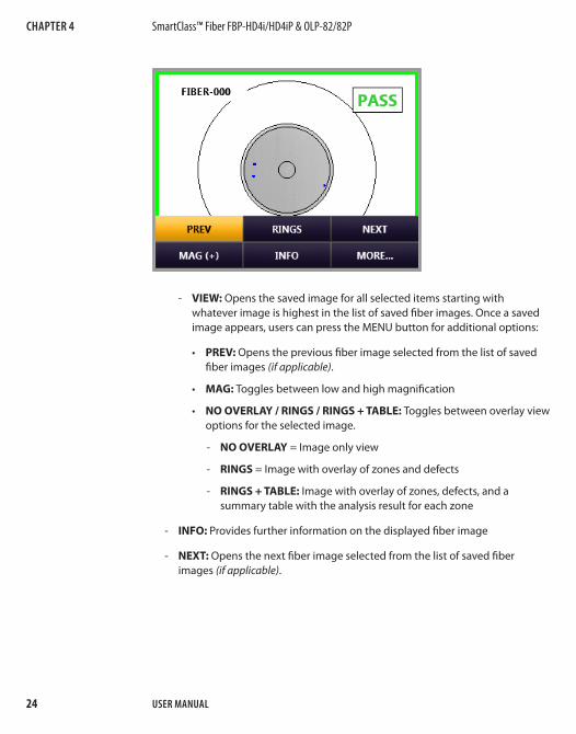
- VIEW: Opens the saved image for all selected items starting with whatever image is highest in the list of saved fiber images. Once a saved image appears, users can press the MENU button for additional options:
• PREV: Opens the previous fiber image selected from the list of saved fiber images (if applicable).
• MAG: Toggles between low and high magnification
• NO OVERLAY / RINGS / RINGS + TABLE: Toggles between overlay view options for the selected image.
- NO OVERLAY = Image only view
- RINGS = Image with overlay of zones and defects
- RINGS + TABLE: Image with overlay of zones, defects, and a summary table with the analysis result for each zone
- INFO: Provides further information on the displayed fiber image
- NEXT: Opens the next fiber image selected from the list of saved fiber images (if applicable).

SmartClass™ Fiber FBP-HD4i/HD4iP and OLP-82/82P 25
Device Setup and Controls CHAPTER 4
Review OPM Data
Opens list of OPM data saved on the device. Each saved result includes the following:
• Measurement value
• Date saved (day/month/year)
• Time saved (hour:minute:second)
• Wavelength
• Frequency (if applicable)
Press the MENU key to select any of the following:
- SELECT ALL: Selects all saved fiber images. When selected, a check indicator will appear in the selection box to the left of the image name.
- DELETE: Deletes any items with a check indicator in the selection box.

USER MANUAL26
CHAPTER 4 SmartClass™ Fiber FBP-HD4i/HD4iP & OLP-82/82P
System Settings
Opens a list of general system settings. When pressed the following menu will appear:
BRIGHTNESS Adjusts the brightness of the display
DATE Adjusts the date
TIME Adjusts the time
AUTO OFF Adjusts the automatic switch-off period of the device
TIME FORMAT Selects between 24-hour or 12-hour time
SYSTEM INFORMATION Displays further information about the device

SmartClass™ Fiber FBP-HD4i/HD4iP and OLP-82/82P 27
Device Setup and Controls CHAPTER 4
BRIGHTNESS
See the BRIGHTNESS section (page 22) earlier in this manual for operation details.
DATE
Once DATE is selected, three fields will appear as follows: [MONTH] [DAY] [YEAR]
To set the date:
1. Select one of the fields to edit
NOTE: The editable field will be highlighted YELLOW.
- Press the left or right ARROW KEYS to select a field, OR
• Tapthedesiredfieldonthetouchscreen.
2. Once selected, press the up or down ARROW KEYS (on either the
control panel or the touch screen) to adjust the desired field.
3. Press the CENTER KEY to confirm.

USER MANUAL28
CHAPTER 4 SmartClass™ Fiber FBP-HD4i/HD4iP & OLP-82/82P
1. Select one of the fields to edit
NOTE: The editable field will be highlighted YELLOW.
- Press the left or right ARROW KEYS to select a field, OR
• Tapthedesiredfieldonthetouchscreen.
2. Once selected, press the up or down ARROW KEYS (on either the
control panel or the touch screen) to adjust the desired field.
3. Press the CENTER KEY to confirm.
TIME
Once TIME is selected, fields will appear as follows:
• 12-hour time format: [HOUR] [MINUTE] [AM/PM]
• 24-hour time format: [HOUR] [MINUTE]
To set the time:

SmartClass™ Fiber FBP-HD4i/HD4iP and OLP-82/82P 29
Device Setup and Controls CHAPTER 4
TIME FORMAT
Select the desired time format (24-hour or 12-hour) that the device will display:
• Press the CENTER KEY or tap the touch screen to select the desired
format.
AUTO OFF
Once AUTO OFF is selected, the following list will appear:
SYSTEM INFORMATION
Displays further information (e.g. Serial Number, Board Revision, Firmware Version, Battery Strength, Up time) about the device. This screen is informational only and does not include anything that can be changed.
• Chose the desired time duration from the list to determine when the device will automatically turn OFF.
• Press the CENTER KEY or tap the touch screen to select the desired
time limit.

USER MANUAL30
CHAPTER 4 SmartClass™ Fiber FBP-HD4i/HD4iP & OLP-82/82P
USER INFO
The USER INFO menu allows you to enter information about your organization, including the company name, address, customer, location, job ID, operator, cable ID, fiber ID, and any comments about the job.
To edit any of these fields, select the desired field via NAVIGATION KEYS or touch screen and enter the data using the alpha-numeric keypad on the screen.
SmartClass™ Fiber FBP-HD4i/HD4iP and OLP-82/82P 31
Device Setup and Controls CHAPTER 4
PC CONNECT
PC CONNECT is used to establish or re-establish a connection between the device and a PC using the included USB-A to Micro-USB cable. Once connected, users can export any of the stored data from the device to the PC using the included FiberChekPRO™ software program.
The device will automatically establish connection with the PC once both ends of the USB-A (connects to PC) to Micro-USB cable (connects to device) are connected. Once connected, a message will appear on the device’s display screen stating that it is connected to the PC. If this connection is lost, this message will disappear. The connection will be re-established by selecting PC CONNECT.
USER MANUAL32
INSPECTION
5Hardware Overview
Inspection of fiber optic interconnects is essential for the optimal performance and longevity of fiber optic connectivity. SmartClass Fiber devices have the capability to inspect end faces, provide PASS/FAIL analysis, and store the results directly on the device. Inspecting fiber endfaces with SmartClass Fiber devices is accomplished with a P5000i Digital Analysis Microscope. In addition, certain configurations are equipped with an Integrated Patch Cord Microscope (PCM) on the device.
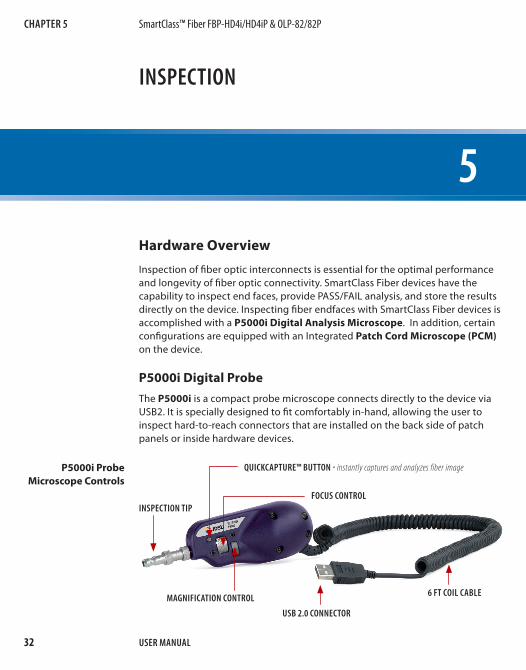
P5000i Digital ProbeThe P5000i is a compact probe microscope connects directly to the device via USB2. It is specially designed to fit comfortably in-hand, allowing the user to inspect hard-to-reach connectors that are installed on the back side of patch panels or inside hardware devices.
P5000i Probe Microscope Controls
FOCUS CONTROL
MAGNIFICATION CONTROL 6 FT COIL CABLE
QUICKCAPTURE™ BUTTON - instantly captures and analyzes fiber image
INSPECTION TIP
USB 2.0 CONNECTOR
CHAPTER 5 SmartClass™ Fiber FBP-HD4i/HD4iP & OLP-82/82P
SmartClass™ Fiber FBP-HD4i/HD4iP and OLP-82/82P 33
Inspection CHAPTER 5
QuickCapture Button Instantly captures and analyzes the fiber image.
Focus Control Allows the user to adjust focus manually of the live fiber end face image on the display.
Magnification Control Allows the user to switch between LOW and HIGH magnifications of the fiber end face image.
NOTE: For further information on the P5000i please refer to the printed FiberChekPRO Quick Start Guide that is included with the P5000i.
P5000i Activation
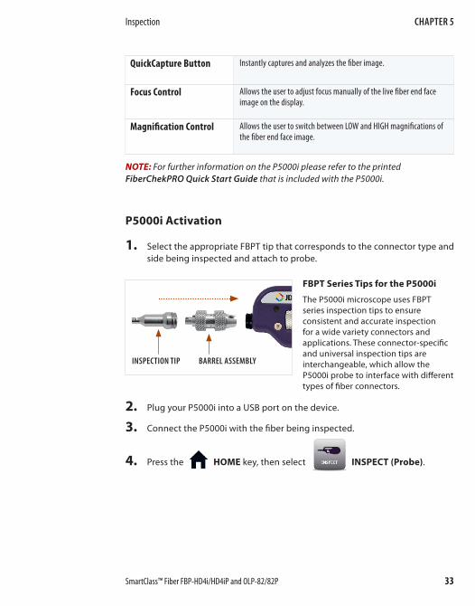
1. Select the appropriate FBPT tip that corresponds to the connector type and side being inspected and attach to probe.
2. Plug your P5000i into a USB port on the device.
3. Connect the P5000i with the fiber being inspected.
4. Press the HOME key, then select INSPECT (Probe).
FBPT Series Tips for the P5000i
The P5000i microscope uses FBPT series inspection tips to ensure consistent and accurate inspection for a wide variety connectors and applications. These connector-specific and universal inspection tips are interchangeable, which allow the P5000i probe to interface with different types of fiber connectors.
INSPECTION TIP BARREL ASSEMBLY

USER MANUAL34
Integrated Patch Cord Microscope (PCM)
Certain SmartClass Fiber devices are also configured with an additional on-board PCM, which allows users to inspect both ends of a fiber connection much faster than with a single probe microscope.
FMAE Series Adapters for the PCM
SmartClass Fiber devices with the PCM use FMAE series adapters to ensure consistent and accurate inspection for a wide variety connectors and applications. All PCM configurations ship with an included 2.5 mm interface. Kitted configurations include additional FMAE adapters.
QuickCapture Button Instantly captures and analyzes the fiber image.
Focus Control Allows the user to adjust focus manually of the live fiber end face image on the display.
Magnification Control Allows the user to switch between LOW and HIGH magnifications of the fiber end face image.
CHAPTER 5 SmartClass™ Fiber FBP-HD4i/HD4iP & OLP-82/82P
PCM Activation
1. Select the appropriate FMAE adapter that corresponds to the connector type and side being inspected and attach to PCM.
2. Press the HOME key, then select INSPECT (PCM).

SmartClass™ Fiber FBP-HD4i/HD4iP and OLP-82/82P 35
INSPECTION MENU (for both P5000i and PCM)
Once the inspection application is active for either the P5000i or PCM, it can display a live view of the fiber end face that it is connected to. The Inspection menu contains all the options necessary for setting up and using the inspection application.
Press the MENU key to select any of the following:
BRIGHTNESS - Adjusts the brightness of the display
PROFILE - Selects the desired PROFILE which contains the analysis parameters by which PASS/FAIL criteria are determined
TEST - Initiates the automated PASS/FAIL test process
TIP / ADAPTER - Selects the best optical settings for the type of tip or adapter that is attached to the microscope
FREEZE - Freezes a live image
MORE... - Access additional inspection options as follows:
• RECALL IMAGE• MICROSCOPE SETTINGS• IMAGE SAVE OPTIONS• SYSTEM SETTINGS• USER INFO
Inspection CHAPTER 5

USER MANUAL36
BRIGHTNESS
Adjusts the brightness of the display. See page 22 for more details.
PROFILE
Allows the user to select from various PROFILES, which contain the analysis parameters by which PASS/FAIL criteria are determined. Users can select from several pre-configured PROFILES already on the device. The pre-configured profiles match the PASS/FAIL criteria in the IEC visual inspection standard, IEC-61300-3-35. All of these profiles are factory set and cannot be edited or removed.
• SM UPC (IEC-61300-3-35)
• SM APC (IEC-61300-3-35)
• MM (IEC-61300-3-35)
• Ribbon, SM APC (IEC-61300-3-35)
• Ribbon, MM (IEC-61300-3-35)
• SM PC (IEC-61300-3-35)
Additional profiles can be created, added, and/or removed from the SmartClass Fiber device when used in conjunction with the included FiberChekPRO software program. For further information on profiles, see the FiberChekPRO user manual on the included software installation disk or visit http://www.jdsu.com/inspect and download the "FiberChekPRO" software.
CHAPTER 5 SmartClass™ Fiber FBP-HD4i/HD4iP & OLP-82/82P

SmartClass™ Fiber FBP-HD4i/HD4iP and OLP-82/82P 37
Inspection CHAPTER 5
TEST
Initiates the automated PASS/FAIL test process.
NOTE: Initiating a test can also be done by pressing the QuickCapture button directly on the P5000i Probe or PCM.
Once the test is complete. The result will flash on the screen as either PASS or FAIL. In addition, the outside edge of the image will be highlighted in either GREEN (to indicate PASS) or RED (to indicate FAIL).
When in the Test view, pressing the [MENU] button again gives the following additional options:
LIVE Returns to a LIVE view of the image
VIEW Toggles overlay view options (3 states):
• NO OVERLAY = image only view• RINGS = image with overlay of zones and defects• RINGS + TABLE = image with overlay of zones, defects, and a
summary table with the analysis result for each zone
MAG Toggles between HIGH(+) or LOW (-) magnification
MORE... Access additional inspection optionsNOTE: This is the same list of options that can be accessed at the Inspection Menu when in a LIVE state (see page 35).

USER MANUAL38
TIP / ADAPTER
Allows the user to select the best optical settings for the type of FBPT Tip or FMAE adapter that is attached to their microscope.
MORE...
Access additional features and functions associated with inspection:
• RECALL IMAGE Opens list of fiber images saved on the device. Select one or multiple saved
fiber images to view further details including analysis results. See page 23 for more details.
FREEZE
Allows the user to freeze a live image. Once the image is frozen, pressing the [MENU] button again gives the following additional options:
CHAPTER 5 SmartClass™ Fiber FBP-HD4i/HD4iP & OLP-82/82P
Text displays "TIP" TIP - When using P5000i
Text displays "ADAPTER" ADAPTER - When using PCM
Users can select from the list of pre-configured optical settings. For further information on optical settings, see the FiberChekPRO user manual on the included software installation disk or visit http://www.jdsu.com/inspect and download the "FiberChekPRO" software.
LIVE Returns to a LIVE view of the image
MAG Toggles between HIGH(+) or LOW (-) magnification
MORE... Access additional inspection optionsNOTE: This is the same list of options that can be accessed at the Inspection Menu when in a LIVE state (see page 35).

SmartClass™ Fiber FBP-HD4i/HD4iP and OLP-82/82P 39
Inspection CHAPTER 5
• MICROSCOPE SETTINGS Opens a list of system settings specific to the microscope functionality. When
selected, the following options will appear:
AUTO CENTER • Check box to turn AUTO CENTER ON• Uncheck box to turn OFF
DEVICE BUTTON Selects the desired function of the QuickCapture button• TEST = initiates the automated PASS/FAIL test process• CAPTURE = freezes image
SHOW FOCUS METER • Check box to turn FOCUS METER ON• Uncheck box to turn OFF
NOTE: The FOCUS METER is a visual gauge that aids the users in finding the optimal focus point. As the image comes into focus, the length of the blue bar increases. A red line will show the highest level achievable for each endface. Optimal focus level is reached when the blue bar is closest to the red line at the highest point possible.

USER MANUAL40
• IMAGE SAVE OPTIONS Allows the user to specify how they want to save an image. Options include the
following:
FILE NAME BASE Allows user to define a base level name for saved images. Selecting this option opens an alphanumeric keypad for entering the base level text.
ARCHIVING METHOD Select from one of the 3:• VERIFY BUTTON BEFORE SAVE
(displays a confirmation box before saving an image)
• ONE BUTTON SAVE (saves the image immediately upon pressing the save button)
• SAVE RESULTS IF PASS (automatically saves the image if the inspection test result is a PASS)
• SYSTEM SETTINGS Shortcut to the SYSTEM SETTINGS. See page 26 for further details.
• USER INFO Shortcut to the USER INFO. See page 30 for further details.
CHAPTER 5 SmartClass™ Fiber FBP-HD4i/HD4iP & OLP-82/82P

SmartClass™ Fiber FBP-HD4i/HD4iP and OLP-82/82P 41
Inspection CHAPTER 5
Page intentionally left blank.

USER MANUAL42
CHAPTER 6 SmartClass™ Fiber FBP-HD4i/HD4iP & OLP-82/82P
OPTICAL POWER MEASUREMENT
6Optical Power Meter
The OLP-82 and OLP-82P models feature a built-in Optical Power Meter (OPM) with multiple calibrated wavelengths from 780 to 1625 nm. The simple, straightforward and intuitive user interface offers a well-organized solution for measuring optical power and saving results with a portable device.
Universal Push-Pull (UPP) Power Meter Input: 2.5 mm (VPP-UPP25) or 1.25 mm (VPP-UPP12) interface.

SmartClass™ Fiber FBP-HD4i/HD4iP and OLP-82/82P 43
Optical Power Measurement CHAPTER 6
Power Meter Controls
dB / dBm - Switches between Absolute (dBm) and Relative (dB) power level unit
SET REF - Stores a reference power level
λ - Select active wavelength
MORE... - Access additional OPM options as follows:
• EDIT WAVELENGTH TABLE• REVIEW OPM DATA• ENABLE WATTS DISPLAY• ENABLE OPM + IMAGE LINK• SYSTEM SETTINGS• USER INFO
dB / dBm
Switches between Absolute (dBm) and Relative (dB) power level unit. For further information on Absolute and Relative Power, see the Measuring Optical Power section on page 47.
NOTE: The device can also display values in Watts. To activate this option, check ENABLE WATTS DISPLAY in the MORE… menu.

USER MANUAL44
CHAPTER 6 SmartClass™ Fiber FBP-HD4i/HD4iP & OLP-82/82P
SET REF
Stores a reference power level.
NOTE: This is used when measuring attenuation (relative power). For further information on measuring Relative Power, see the Measuring Optical Power section on page 47.
λ (WAVELENGTH)
Selects the desired active wavelength for testing.
NOTE: The wavelength values that appear in this list is managed in the EDIT WAVELENGTH TABLE under MORE… (see next section for details).
Upon selection, a list of all the wavelengths will appear as shown above. Each wavelength in this list will include the following:
- Checkbox > Located on the left side. Checked items will appear on the
WAVELENGTH λ list on the main OPM screen. Press the CENTER
KEY or use the touchscreen to check or uncheck this box.
MORE...
Access additional OPM options as follows:
• EDIT WAVELENGTH TABLE

SmartClass™ Fiber FBP-HD4i/HD4iP and OLP-82/82P 45
Optical Power Measurement CHAPTER 6
- Wavelength value
- REF > Displays a stored reference value (in dBm)
- Limit > Displays a set limit value (if defined). For further details, see the ENTER LIMIT section below.
• Press the MENU button for the following:
- ADD WAVELENGTH λ > Activates a numeric keypad to enter additional wavelengths
- ENTER REFERENCE > Activates a numeric keypad to manually enter a Reference Threshold
- DELETE WAVELENGTH > Deletes the current highlighted wavelength
- ENTER LIMIT > Activates a numeric keypad for entering a threshold for the lowest acceptable value. If the OPM value being measured is lower than the acceptable threshold, then the word FAIL will appear on the MAIN OPM screen with an explanation that is below the acceptable limit.

USER MANUAL46
CHAPTER 6 SmartClass™ Fiber FBP-HD4i/HD4iP & OLP-82/82P
• REVIEW OPM DATA
Opens list of OPM data saved on the device. Each saved result includes the following:
- Measurement value- Date saved (day/month/year)- Time saved (hour:minute:second)- Wavelength- Frequency
Press the MENU button to determine the following:
- SELECT ALL > Selects all saved fiber images. When selected, a check indicator will appear in the selection box to the left of the image name
- DELETE > Deletes any items with a check indicator in the selection box
• ENABLE WATTS DISPLAY
Check this box to include WATTS as one of the measurement values.
• ENABLE OPM + IMAGE LINK
Check this box to group the current OPM reading with the last saved inspection image. All saved OPM readings will be grouped together with the last saved inspection image, until a new image is stored.

SmartClass™ Fiber FBP-HD4i/HD4iP and OLP-82/82P 47
Optical Power Measurement CHAPTER 6
• SYSTEM SETTINGS
Shortcut to the SYSTEM SETTINGS. See page 26 for further details.
• USER INFO
Shortcut to the USER INFO. See page 30 for further details.
Measuring Optical Power
Measuring Absolute Power
Absolute power (measured in dBm) is the amount of optical power present in the system. The source of this power is the transmitter or transceiver sending information through the system. This test determines whether the signal has enough power to operate the receiver or transceiver at the end of the link.
To measure absolute power:
1. Select dBm from the menu.
2. Press Select the active wavelength (as described in the WAVELENGTH section below).
3. The optical power measurement is displayed on the power meter display.

USER MANUAL48
CHAPTER 6 SmartClass™ Fiber FBP-HD4i/HD4iP & OLP-82/82P
Measuring Attenuation (Relative Power)
Relative power level (attenuation measurement) is the amount of power lost (attenuated) by the optical link being tested, measured in dB. The source of this power is typically a handheld optical light source. This test determines whether the optical link is constructed properly, either as a qualification test or when troubleshooting the network.
To measure attenuation, you must:
1. Get a reference measurement by selecting SET REF on the menu. Once the reference is set, 0.00 dB is displayed in the main OPM window. The referenced value will also appear on the display.
2. Get an attenuation measurement:
a) Disconnect reference fiber 1 from the power meter (DO NOT disconnect reference fiber 1 from the light source [OLS])
b) INSPECT and if necessary, CLEAN all ends of the system port
c) Connect reference fiber 1 to the system port
d) INSPECT and if necessary, CLEAN all ends of reference fiber 2
e) INSPECT and if necessary, CLEAN the fiber at the far end of the optical fiber link
f) Connect reference fiber 2 to the system port
g) The attenuation measurement (insertion loss) of the optical link is displayed in the main window of the power meter

SmartClass™ Fiber FBP-HD4i/HD4iP and OLP-82/82P 49
SmartClass™ Fiber FBP-HD4i/HD4iP & OLP-82/82P
SPECIFICATIONS
General
General technical (Typical at 25°C)
Weight 1.2 lb (1.4 lb for PCM version)
Dimensions (H x W x D) OLP-82/HD4i 20.83 x 11.18 x 6.35 cm
(8.2 x 4.4 x 2.5 in) OLP-82P/HD4iP 20.83 x 152.4 x 6.35 cm
(8.2 x 6.0 x 2.5 in)
Video display 3.5 in color LCD, 4:3 ratioKeypad 11+2 dome-buttons membrane panels 4 LED indicators
Connector USB 2.0 (2 x host, Type A; 1 x device, Micro-B)
Power source 12V 2A adapter, battery (8X AA alkaline or rechargeable Li-ION), USB port
Run time Rechargeable Li-ION = minimum) 8 hours 8X AA alkaline 5 hours
Power mode Active, Auto-offAuto-shutoff time user programmableCharge time AC adaptor 8 hours
Saved images > 1000Saved OPM data > 10,000
Certification CE, IEC/EN61326Warranty 1 year
OPM
General technical (Typical at 25°C)
Display range Standard –65 to +10 dBm High power –50 to +26 dBm
Max. input level permitted Standard +10 dBm High power +26 dBm
Standard wavelength settings 850, 980, 1300, 1310, 1490, 1550, 1625 nm
Intrinsic uncertainty1 ±0.20 dB (±5%)Linearity1 ±0.06 dB (–50 to +5 dBm)
Wavelength range 780 to 1700 nmWavelength and modulation Result display dBm, dB, MW Resolution 0.01 dB Modulation frequencies 270Hz, 1000Hz, 2000Hz Sensor InGaAs
Video Display
General technical (Typical at 25°C)
Live image 320 x 240 x 8 bit gray, 10 fpsLight source Blue LED, 100,000+ hour lifeLighting technique CoaxialLow-magnification field-of-view (FOV) Horizontal 740 μm Vertical 550 μm
High-magnification field-of-view (FOV) Horizontal 370 μm Vertical 275 μm

USER MANUAL50
SmartClass™ Fiber FBP-HD4i/HD4iP & OLP-82/82P
ORDERING INFORMATION
Standalone Units
Part Number Description
FBP-HD4i HD4i Digital Handheld Video Display
FBP-HD4iP HD4i Digital Handheld Video Display,Dual-Mag Patch Cord Module
2315/05 OLP-82 Digital Handheld Video Display,Integrated Optical Power Meter
2315/03 OLP-82 Digital Handheld Video Display,Integrated High-Power Optical Power Meter
2316/01 OLP-82P Digital Handheld Video Display,Dual-Mag Patch Cord Module, Integrated OPM
2316/03 OLP-82P Digital Handheld Video Display,Dual-Mag Patch Cord Module,Integrated High-Power OPM
Included Items
Standalone Units
SmartClass Fiber Instrument
Soft Bag for SmartClass Fiber and AccessoriesFiberChekPRO Software Installation DiskUSB Cable USB-A to Micro-USBQuick Start Manual and Safety InstructionsDry Batteries (8x)
Additional Items in Basic Kits
P5000i Digital Inspection Microscope
Inspection Tips and Adapters (Bulkhead: SC and LC, Patch Cord: 2.5 and 1.25 mm)
1.25 mm OPM Adapter OLP-82/82P
Additional Items in Pro Kits
P5000i Digital Inspection Microscope
Inspection Tips and Adapters (Bulkhead: SC and LC, Patch Cord: 2.5 and 1.25 mm)
1.25 mm OPM Adapter OLP-82/82PCleaning Materials for 2.5 and 1.25 mm (Bulkhead and Patch Cord)Hands-Free Carrier for SmartClass FiberRechargeable Battery for SmartClass Fiber (Li-ION)FFL-050 Visual Fault Locator with 2.5 and 1.25 mm AdapterPower supply for SmartClass Fiber (12V)
Kits
Part Number Description
FBP-SD4i HD4i Basic Kit
FBP-SD4i-PRO HD4i Pro Kit
FBP-SD4iP HD4iP Basic Kit
FBP-SD4iP-PRO HD4iP Pro Kit
FIT-8201 OLP-82 Basic Kit
FIT-8201-PRO OLP-82 Pro Kit
FIT-82P01 OLP-82P Basic Kit
FIT-82P01-PRO OLP-82P Pro Kit
FIT-82P03 OLP-82P High Power, Basic Kit
FIT-82P03-PRO OLP-82P High Power, Pro Kit
Accessories
Part Number Description
FBPP-PS4 Power Supply for Smart Class Fiber (12 V)FITP-RBP2 Rechargeable Battery for SmartClass Fiber (Li-ION)FITP-RCG1 Kit: RBP2 Rechargeable Battery, PS4 Power SupplyFITP-RBT1 Replacement Battery Tray
FITP-UC4 UC4 Hands-Free Carrier for SmartClass Fiber
FITP-UC4P UC4P Hands-Free Carrier for SmartClass Fiber with PCM
VPP-UPP12 Adapter U12 for OLP-82/82P
VPP-UPP25 Adapter U25 for OLP-82/82P
FBPP-SCASE2 SCASE2 Soft Shoulder Case for SmartClass Fiber Tools

NORTH AMERICATEL: 1 866 228 3762FAX: 1 301 353 9216
LATIN AMERICATEL: +1 954 688 5660FAX: +1 954 345 4668
ASIA PACIFICTEL: +852 2892 0990FAX: +852 2892 0770
EMEATEL: +49 7121 86 2222FAX: +49 7181 86 1222
www.jdsu.com/inspect
Test and Measurement Regional Sales
22002224REV 0
Product specifications and descriptions in this document subject to change without notice. © 2012 JDS Uniphase Corporation. September 2012
Top Related