


Languages
Pages
Legal


www.renesas.com 2017.09
SMART METERSOLUTIONSCatalog
01-02
Role Of Smart Meters and Market Trends _______________________ 02
Smart Meter Solutions from Renesas
Metrology Unit _________________________________________ 03
Communication Unit ______________________________________ 04
System Suggestions for Smart Meters
Electricity Meters ________________________________________ 07
Gas and Water Meters ____________________________________ 08
Renesas Device Recommendations
Devices _______________________________________________ 09
Evaluation Boards _______________________________________ 10
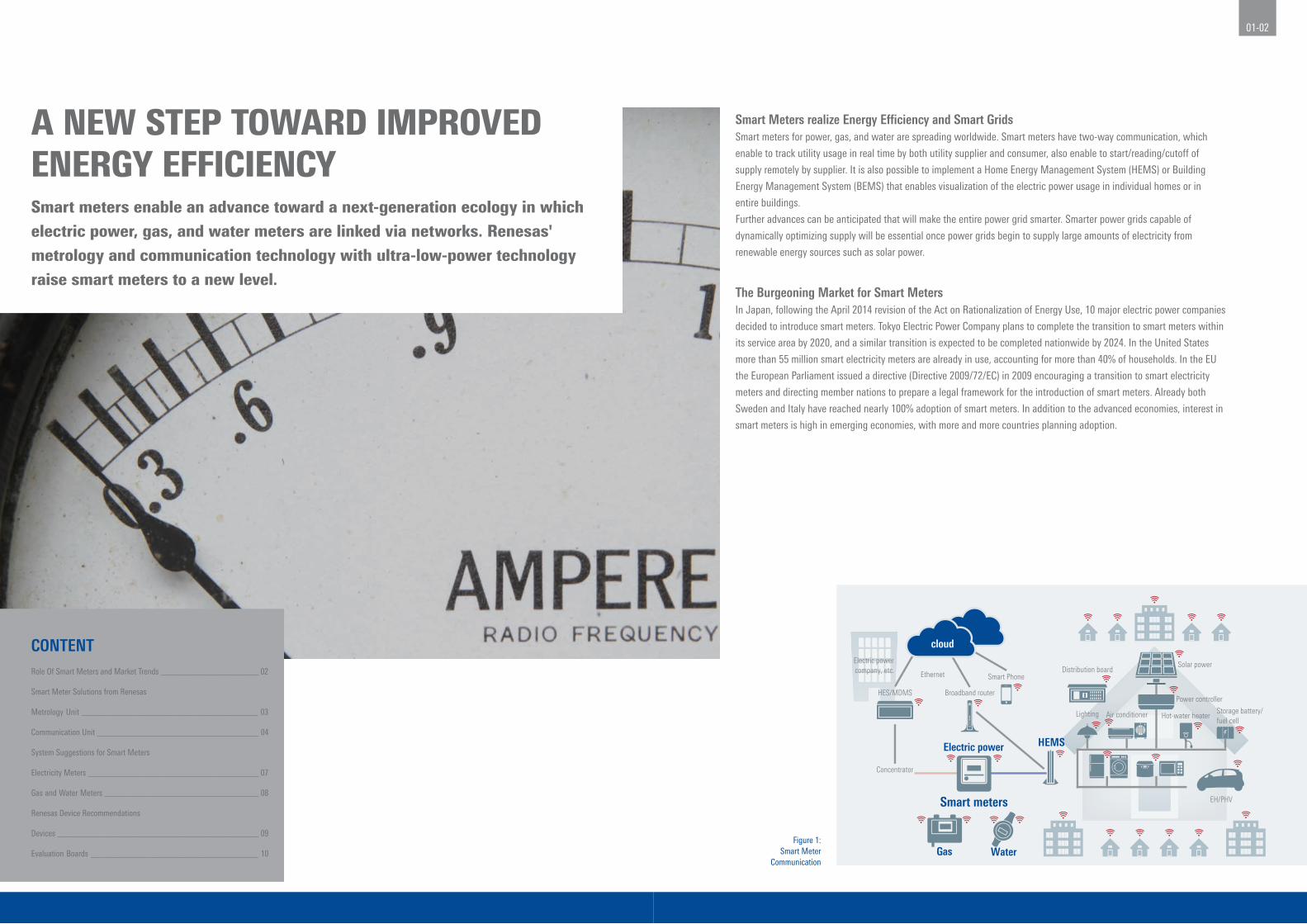
Smart Meters realize Energy Efficiency and Smart GridsSmart meters for power, gas, and water are spreading worldwide. Smart meters have two-way communication, which
enable to track utility usage in real time by both utility supplier and consumer, also enable to start/reading/cutoff of
supply remotely by supplier. It is also possible to implement a Home Energy Management System (HEMS) or Building
Energy Management System (BEMS) that enables visualization of the electric power usage in individual homes or in
entire buildings.
Further advances can be anticipated that will make the entire power grid smarter. Smarter power grids capable of
dynamically optimizing supply will be essential once power grids begin to supply large amounts of electricity from
renewable energy sources such as solar power.
The Burgeoning Market for Smart MetersIn Japan, following the April 2014 revision of the Act on Rationalization of Energy Use, 10 major electric power companies
decided to introduce smart meters. Tokyo Electric Power Company plans to complete the transition to smart meters within
its service area by 2020, and a similar transition is expected to be completed nationwide by 2024. In the United States
more than 55 million smart electricity meters are already in use, accounting for more than 40% of households. In the EU
the European Parliament issued a directive (Directive 2009/72/EC) in 2009 encouraging a transition to smart electricity
meters and directing member nations to prepare a legal framework for the introduction of smart meters. Already both
Sweden and Italy have reached nearly 100% adoption of smart meters. In addition to the advanced economies, interest in
smart meters is high in emerging economies, with more and more countries planning adoption.
A NEW STEP TOWARD IMPROVED ENERGY EFFICIENCYSmart meters enable an advance toward a next-generation ecology in which electric power, gas, and water meters are linked via networks. Renesas' metrology and communication technology with ultra-low-power technology raise smart meters to a new level.
Figure 1: Smart Meter
Communication
Smart Phone
Broadband router
HEMS
Distribution board
Hot-water heater
EH/PHV
Storage battery/fuel cell
Air conditionerLighting
Solar power
Power controller
Concentrator
Electric power
Gas Water
Smart meters
cloud
Ethernet
Electric power company, etc.
HES/MDMS
CONTENT

03-04
Communication links bring new value. Renesas’ technological expertise can help reduce development time while making possible highly sophisticated smart meters.
Metrology Unit Communication Unit
RL78/I1B: A Microcontroller with Outstanding Energy EfficiencyThe RL78/I1B is a microcontroller developed specifically for use in
electricity meters. It delivers superior energy efficiency, reducing the
power consumed by the meter itself to an absolute minimum. The
RL78/I1B, a microcontroller developed specifically for use in smart
meters, is used in the metrology unit of the electricity meters. The
superior energy efficiency of the RL78/I1B reduces the electric power
consumed by the meter itself to an absolute minimum.
The metrology unit of the smart meter includes a clock function
implemented by means of a real-time clock (RTC), which requires a
backup battery. Previously, an external low-power RTC IC was used for
this purpose, but the RL78/I1B includes a newly developed integrated
ultra-low-power RTC. In addition, the on-chip oscillator has a function
that automatically corrects the clock frequency within a range of
±0.05%. This enables highly precise metrology without the need for
external components. The oscillation circuit has a high tolerance for
power surges caused by lightning, etc., ensuring stable operation in the
harsh outdoor environments that smart meters must withstand.
Complex Smart Meter Communication Involving Multiple StandardsThe biggest feature of smart meters is their communication
functionality. This functionality links the power supplier (the electric
power company) and the consumer (the device in the home) (see Figure
1 on page 2), but a variety of communication standards are used in
different countries and regions.
In Japan, wireless multi-hop, 1:N wireless, and PLC are being
considered for communication between the supplier and smart meter.
For communication within the home (or building), Wi-SUN wireless
communication, supplemented by power line communication (PLC), are
the main methods employed.
Overseas, Wi-SUN and PLC hold the dominant positions, while a
variety of other methods such as wireless multi-hop, 2G or 3G mobile
communication, and ZigBee® wireless communication are under
consideration.
Microcontroller RL78/I1C: Even More Advanced than the RL78/I1B, with Enhanced SecurityThe newly developed RL78/I1C microcontroller is even more advanced
than its previous products the RL78/I1B, while maintaining superior
measuring accuracy and energy efficiency. Its features include (1)
hardware implementation of security functions, an industry first, (2)
30% better computational performance, up to 256 KB of ROM for code
storage, and single-chip implementation of electric power metrology
processing and DLMS* processing, resulting in approximately 30%
lower power consumption than when two chips are used, and (3)
availability of a Meter Analog Evaluation Kit and Meter Reference
Kit, for a reduction of about 25% in the time and cost required for
development.
The RL78/I1C also has enhanced event link controller and phase
adjustment functions linked to a 24-bit Δ∑ A/D converter module with
four channels and a 10-bit sequential-transformation power data A/D
converter module with three channels. This provides seven channels for
current and voltage metrology, as required for three-phase, four-wire
metering. The RL78/I1C thus supports three-phase, four-wire metering
in addition to conventional single-phase, two-wire and three-phase,
three-wire configurations.* DLMS stands for Device Language Message Specifi cation, an IEC standard for converting electric power company meter metrology data.
PLC for Smart Meters, different from PLC for Data TransferPower line communication over wires designed to supply AC by
overlaying an information signal at a higher frequency than the AC
frequency (50 or 60 Hz) (Figure 4). PLC for smart meters is implemented
using a variety of standards worldwide: G3 and PRIME are dominant
in Europe, IEEE 1901.2 is used in the United States, Meters & More
has been adopted Italy, and in Japan G3 format PLC (G3-PLC) is used.
Renesas is involved in the standardization processes for all of these. In
particular, Renesas has participated in all the working groups leading
to the standardization of G3 and PRIME.
Electricity Meter Development Kits You Can Start Using Right AwayTwo development kits incorporating the RL78/I1B are available: the
Analog Characteristic Evaluation Kit (Figure 2) and the Single-Phase
Reference Meter (Figure 3). They include firmware developed based on
Renesas extensive experience, such as electricity metering firmware
and firmware for calibrating sensor readout values, so development can
proceed more efficiently.
The Analog Characteristic Evaluation Kit can be used to confirm the
compatibility of the RL78/I1B with the sensors currently in use for
evaluation of characteristics. This kit enables developers to incorporate
their own electricity metering knowhow into the RL78/I1B. The Single-
Phase Reference Meter provides all basic functionality required for
electricity metering. It includes everything needed to build a metrology
unit that complies with the IEC 62053 international standard for
electronic power metrology and delivers metrology accuracy of 0.5%.
Wi-SUN Sub-GHz Wireless CommunicationDifferent frequency bands are used for sub-GHz wireless
communication: 920 MHz in Japan, 915 MHz in the United States, and
863 MHz in Europe. Also, the Wi-SUN standard has been adopted with
the aim of popularizing the Internet of Things (IoT) through applications
such as machine-to-machine (M2M) communication and sensor
networks.
Wi-SUN is a low-speed communication method employing IEEE
802.15.4g for the physical layer and IEEE 802.15.4e for the MAC
layer. IEEE 802.15.4e and IEEE 802.15.4g are required items under
the standard, but Wi-SUN extracts only the stipulations necessary for
operation. Renesas has been involved since the beginning as one of the
core players helping to determine the standard.
Smart Meter Solutions from Renesas
Figure 2: Analog Characteristic Evaluation Kit
Figure 3: Single-Phase Reference Meter
Features of Sub-GHz Communication
1 Covers a long range
2 High diffraction (ability to bypass obstacles)
3 Low interference
4 Low-speed (ability to maintain communication among multiple devices)
Wi-SUN is a registered trademark of Wi-SUN Alliance, Inc., Renesas is licensed to use this trademark.
Figure 4: Basic Operating Principle of Power Line Communication (PLC)
Metrology functionality is the purpose of a meter. Renesas development kits for smart electricity meters make development work more efficient.
Information signal is separated from AC power and extracted.
AC power (50/60 Hz)
Power line
AC power+
Information signal
PLC modem
Voltage
Time
Information signal
Voltage
Time
AC power (50/60 Hz)
Power line
Voltage
Time
Information signal
Voltage
Time
PLC signal
Voltage
Time
05-06
Differences in Interoperability and Connectivity Due to How Communication Is ImplementedCommunication is regulated by very strict standards. A newly
developed communication unit must undergo and pass certification
testing by the standardizing body before it can operate using the
standard.
In addition, it must be possible to connect to other devices. Even if a
device passes certification testing, a variety of factors other than the
standard used affect connectivity. For this reason the standardizing
body also conducts interoperability testing. Due to disparities in
connectivity that can result from different implementations, it is in fact
quite difficult to develop the communication unit of a smart meter. By
using Renesas solutions that have completed the certification process,
the development workload can be reduced substantially. This allows
the developer to focus on enhancing the appeal of the smart meter
itself and makes it possible to create a more competitive product.
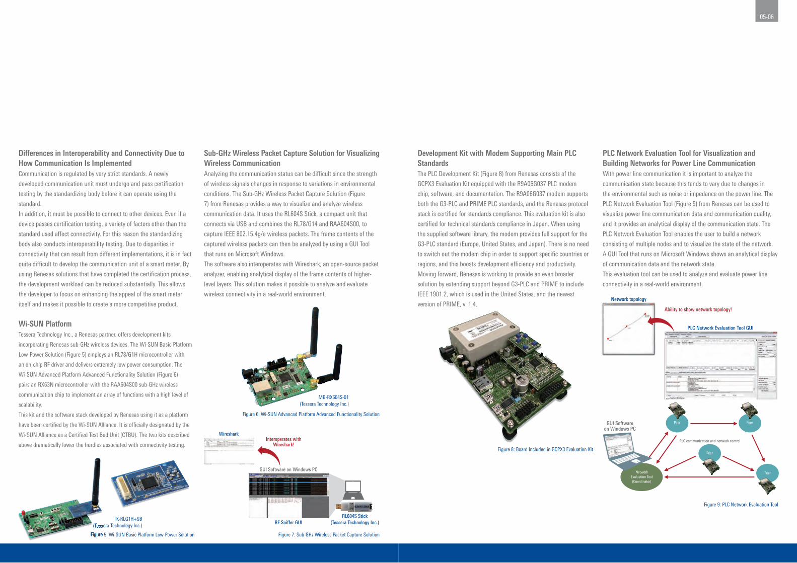
Development Kit with Modem Supporting Main PLC StandardsThe PLC Development Kit (Figure 8) from Renesas consists of the
GCPX3 Evaluation Kit equipped with the R9A06G037 PLC modem
chip, software, and documentation. The R9A06G037 modem supports
both the G3-PLC and PRIME PLC standards, and the Renesas protocol
stack is certified for standards compliance. This evaluation kit is also
certified for technical standards compliance in Japan. When using
the supplied software library, the modem provides full support for the
G3-PLC standard (Europe, United States, and Japan). There is no need
to switch out the modem chip in order to support specific countries or
regions, and this boosts development efficiency and productivity.
Moving forward, Renesas is working to provide an even broader
solution by extending support beyond G3-PLC and PRIME to include
IEEE 1901.2, which is used in the United States, and the newest
version of PRIME, v. 1.4.
PLC Network Evaluation Tool for Visualization and Building Networks for Power Line CommunicationWith power line communication it is important to analyze the
communication state because this tends to vary due to changes in
the environmental such as noise or impedance on the power line. The
PLC Network Evaluation Tool (Figure 9) from Renesas can be used to
visualize power line communication data and communication quality,
and it provides an analytical display of the communication state. The
PLC Network Evaluation Tool enables the user to build a network
consisting of multiple nodes and to visualize the state of the network.
A GUI Tool that runs on Microsoft Windows shows an analytical display
of communication data and the network state.
This evaluation tool can be used to analyze and evaluate power line
connectivity in a real-world environment.
TK-RLG1H+SB(Tessera Technology Inc.)
MB-RX604S-01(Tessera Technology Inc.)
Figure 5: Wi-SUN Basic Platform Low-Power Solution
Figure 8: Board Included in GCPX3 Evaluation Kit
Figure 6: Wi-SUN Advanced Platform Advanced Functionality Solution
Figure 7: Sub-GHz Wireless Packet Capture Solution
Figure 9: PLC Network Evaluation Tool
WiresharkInteroperates with
Wireshark!
GUI Software on Windows PC
RF Sniffer GUIRL604S Stick
(Tessera Technology Inc.)
Network topology
Ability to show network topology!
GUI Softwareon Windows PC
PLC communication and network control
PLC Network Evaluation Tool GUI
Peer Peer
Peer
Peer
NetworkEvaluation Tool(Coordinator)
Wi-SUN PlatformTessera Technology Inc., a Renesas partner, offers development kits
incorporating Renesas sub-GHz wireless devices. The Wi-SUN Basic Platform
Low-Power Solution (Figure 5) employs an RL78/G1H microcontroller with
an on-chip RF driver and delivers extremely low power consumption. The
Wi-SUN Advanced Platform Advanced Functionality Solution (Figure 6)
pairs an RX63N microcontroller with the RAA604S00 sub-GHz wireless
communication chip to implement an array of functions with a high level of
scalability.
This kit and the software stack developed by Renesas using it as a platform
have been certified by the Wi-SUN Alliance. It is officially designated by the
Wi-SUN Alliance as a Certified Test Bed Unit (CTBU). The two kits described
above dramatically lower the hurdles associated with connectivity testing.
(Tessera Technology Inc.)
Figure 5: Wi-SUN Basic Platform Low-Power Solution
Sub-GHz Wireless Packet Capture Solution for Visualizing Wireless CommunicationAnalyzing the communication status can be difficult since the strength
of wireless signals changes in response to variations in environmental
conditions. The Sub-GHz Wireless Packet Capture Solution (Figure
7) from Renesas provides a way to visualize and analyze wireless
communication data. It uses the RL604S Stick, a compact unit that
connects via USB and combines the RL78/G14 and RAA604S00, to
capture IEEE 802.15.4g/e wireless packets. The frame contents of the
captured wireless packets can then be analyzed by using a GUI Tool
that runs on Microsoft Windows.
The software also interoperates with Wireshark, an open-source packet
analyzer, enabling analytical display of the frame contents of higher-
level layers. This solution makes it possible to analyze and evaluate
wireless connectivity in a real-world environment.
07-08
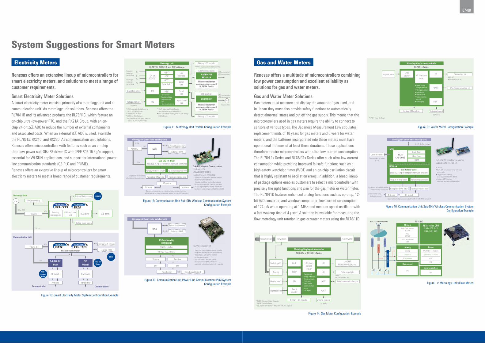
Renesas offers an extensive lineup of microcontrollers for smart electricity meters, and solutions to meet a range of customer requirements.
Renesas offers a multitude of microcontrollers combining low power consumption and excellent reliability as solutions for gas and water meters.
Electricity Meters Gas and Water Meters
Smart Electricity Meter SolutionsA smart electricity meter consists primarily of a metrology unit and a
communication unit. As metrology unit solutions, Renesas offers the
RL78/I1B and its advanced products the RL78/I1C, which feature an
on-chip ultra-low-power RTC, and the RX21A Group, with an on-
chip 24-bit Δ∑ ADC to reduce the number of external components
and associated costs. When an external Δ∑ ADC is used, available
the RL78L1x, RX210, and RX220. As communication unit solutions,
Renesas offers microcontrollers with features such as an on-chip
ultra-low-power sub-GHz RF driver IC with IEEE 802.15.4g/e support,
essential for Wi-SUN applications, and support for international power
line communication standards (G3-PLC and PRIME).
Renesas offers an extensive lineup of microcontrollers for smart
electricity meters to meet a broad range of customer requirements.
Gas and Water Meter SolutionsGas meters must measure and display the amount of gas used, and
in Japan they must also provide safety functions to automatically
detect abnormal states and cut off the gas supply. This means that the
microcontrollers used in gas meters require the ability to connect to
sensors of various types. The Japanese Measurement Law stipulates
replacement limits of 10 years for gas meters and 8 years for water
meters, and the batteries incorporated into these meters must have
operational lifetimes of at least those durations. These applications
therefore require microcontrollers with ultra-low current consumption.
The RL78/L1x Series and RL78/G1x Series offer such ultra-low current
consumption while providing improved failsafe functions such as a
high-safety watchdog timer (WDT) and an on-chip oscillation circuit
that is highly resistant to oscillation errors. In addition, a broad lineup
of package options enables customers to select a microcontroller with
precisely the right functions and size for the gas meter or water meter.
The RL78/I1D features enhanced analog functions such as op-amp, 12-
bit A/D converter, and window comparator; low current consumption
of 124 μA when operating at 1 MHz; and medium-speed oscillator with
a fast wakeup time of 4 μsec. A solution is available for measuring the
flow metrology unit rotation in gas or water meters using the RL78/I1D.
System Suggestions for Smart Meters
Figure 10: Smart Electricity Meter System Confi guration Example
Figure 11: Metrology Unit System Confi guration Example
Figure 12: Communication Unit Sub-GHz Wireless Communication System Confi guration Example
Figure 13: Communication Unit Power Line Communication (PLC) System Confi guration Example
Figure 14: Gas Meter Confi guration Example
Figure 15: Water Meter Confi guration Example
Figure 16: Communication Unit Sub-GHz Wireless Communication System Confi guration Example
Figure 17: Metrology Unit (Flow Meter)
Electricity metrology unit
Communication Communication
Metrology Unit
LCD driver
High-frequency
device
Global PLCModem
SRAM
E2PROM
Sub-GHz RF
driver
PLC
Modem
100 or 200V
5V, 1A
3.3V
3.0V
RF switch Driver/Amp
Antenna Transformer
External flash memory
External RAMFlash microcontroller
External flash memory
LCD panel
Power sensing
Power IC5.0V
CPU calculationunit
Backup power supply
Power IC
Communication Unit
5V, 1A
3.3V
3.0VSub-GHz RF driver
(IEEE 802.15.4g/4e–compliant hardware functions)
Antenna Antenna
External flash memory
External RAMMCU
Metrology unit (smart meter metrology unit)
High-frequency voltage suppression functionReception matching function
Reception SAW filter
RF switch
Transmission matching circuitSuppression of interference
with mobile wireless base station
• Diversity antenna system to maintain communication robustness• Smart electricity meter transmission output: 20 mW (ARIB-compliant)
Sub-GHz Wireless Communication Evaluation Kit (RAA604S00/RX63N)Sub-GHz RF driver IC (RAA604S00)• Automatic discrimination between two sets of communication addresses• Reception matching function that reduces burden associated with changing constants• On-chip high-frequency voltage suppression function to support Japanese Radio Law (ARIB)
Sub-GHz Wireless Communication
Power IC
PLC modem chipR9A06G037
External flash memory
External RAMMCU
Metrology unit (smart meter metrology unit)
Tx driverRx amp
MAC controller
PHY(G3-PLC, PRIME)
BPF
Transformer
BPF
GCPX3 Evaluation Kit
• Power line communication modem featuring low power consumption and robust stability • Protocol stack with G3-PLC platform certification available• Test environment matched to each development step (PHY performance evaluation, network evaluation, etc.) available
Zero Cross (Option)
• RX21A requires external LCD controller.
*1 ADC: Analog to Digital Converter*2 WDT: Watch Dog Timer*3 POR: Power On Reset*4 OCO: On-Chip Oscillator*5 AES: Advanced Encryption Standard (RL78/I1C, and RX21A Groups)
*6 AMR: Automated Meter Reading*7 AMI: Advanced Meter Infrastructure• Data flash is flash memory used for data storage (RX21A Group).
32.768kHz
24-bit∆ΣADC*1
I/O
RTC
WDT*2
RL78/I1B, RL78/I1C, and RX21A Groups
POR*3
AMR communication*6
AMI communication*7
AMR communicationAMI communication
OCO*4
AES*5
Data flash※
Metrology Unit
• Power calculation•Metrology result display• AMR communication• Clock• Power interruption detection
Display LCD module
Display LCD module
Sub-GHz wireless solution
Microcontroller forcommunication control
RL78/RX Family
RAA604S00RL78/G1H
PLC solution
Microcontroller forcommunication control
RL78/RX Family
R9A06G037Large-currentI/O
SerialI/O
SerialI/O
LCDcontroller
Voltage element
Operation keys
To current metrology circuit block
IA
IB
To voltage metrology circuit block
To power line
VA
VB
*1 ADC : Analog to Digital Converter*2 POR : Power On Reset*3 LCD drive control circuit: Integrated in RL78/L1x Series
LCD drivecontrolcircuit*3
RL78/L1x or RL78/G1x Series
MOS FETRQJ0203WGDQA, etc.
Metrology/display microcontroller
• Power supply voltage detection• Timing generation• Event count• Pulse control• Communication control• LCD display
UART
POR*2
UART
ADC*1
I/O
Eventcounter
Pulse output pin
Cutoff valve
32.768kHz
Magnetic sensor
Vibration sensor
Op-amp
Metrology IC
Flow meterPressure sensor
Display LCD module Voltage element
Wired communication pin
I/O
I/OMOS FET
RQJ0203WGDQA, etc.
*1 POR : Power On Reset
LCD drive controlcircuit
RL78/L1x Series
MOS FETRQJ0203WGDQA, etc.
Metrology/display microcontroller
• Power supply voltage detection• Timing generation• Event count• Pulse control• Communication control• LCD display POR*1
Eventcounter
Pulse output pin
32.768kHz
Magnetic sensor
Display LCD module Voltage element
Wired communication pinUART
I/O
Lithium battery
Sub-GHz RF driver(IEEE 802.15.4g/4e–compliant hardware functions)
Antenna
Code flash
Data flash
RAM
RL78CPU CORE
MCU
RF block
Metrology unit (smart meter metrology unit)
High-frequency voltage suppression functionReception matching function
Reception SAW filter
RF switch
Transmission matching circuitSuppression of interference with
mobile wireless base station
Communication using U-Bus Air protocol
Power supplied by battery (3.0 V)
Gas smart meter transmission output: 1 mW, 10 mW (ARIB-compliant)
Sub-GHz Wireless Communication Evaluation Kit (RL78/G1H)
RL78/G1H• RL78 CPU core, renowned for low power consumption• Large-capacity memory (code flash: 512 KB/RAM: 48 KB)• Integrated RF functions (functional emulation of RAA604S00)
UART (U-Bus protocol)
Code Flash memory8-32KB
Memory
RAM0.7-3KB
Data Flash memory2KB
RL78 16-bit CPU24 MHz: 2.7V – 3.6 V
4 MHz: 1.6V – 3.6 V
RL78/I1D
SAU
Communication
Op-amp
Comparator
A/D converter
AnalogTAU 16-bit × 4 channels
12-bit interval ×1 channel
WDT
RTC
Timers
DTC
Bus control
Coil
B
90 to 120˚ sensor alignment
Coil
A
Coil
R
Rect
ifier
& F
ilter

09-10
Devices
Block Product
Classification Recommended
Product Features
Metrology Microcontroller RL78/I1B(electricity meter metrology ASSP)
16-bit CPU • Max. operating frequency: 24 MHz, multiply/divide/multiply-and-accumulate instructionsOn-chip memory • Flash memory: 64/128 KB • SRAM: 6/8 KBSystem • HOCO clock frequency correction function • Battery backup functionLCD drive • 8 com. × 38 seg./6 com. × 40 seg./4 com. × 42 seg. • LCD drive power supply generation: Internal voltage boosting method/capacitor split method/external resistance division Analog • 24-bit Δ∑ A/D converter × 4 channels • 8-/10-bit ADC × 6 channels, temperature sensor × 1 channel Package • LQFP 80-/100-pins
Microcontroller RL78/I1C(electricity meter metrology ASSP)
16-bit CPU • Max. operating frequency: 32 MHz, multiply/divide/multiply-and-accumulate instructions, 32-bit multiply-and-accumulate circuitOn-chip memory • Flash memory: 64/128/256 KB • Data flash: 2 KB • SRAM: 6/8/16 KBSystem • AES hardware (GCM/ECB/CBC mode) • Independent power supply RTC system • HOCO clock frequency correction function • Battery backup function • ELCLCD drive • 8 com. × 38 seg./6 com. × 40 seg./4 com. × 42 seg. • LCD drive power supply generation: Internal voltage boosting method/capacitor split method/external resistance division Analog • 24-bit Δ∑ A/D converter × 4 channels • 8-/10-bit ADC × 6 channels, temperature sensor × 1 channel Package • LQFP 64-/80-/100-pins
Microcontroller RL78/I1D 16-bit CPU • Max. operating frequency: 24 MHz, multiply/divide/multiply-and-accumulate instructionsOn-chip memory • Flash memory: 8/16/32 KB • SRAM: 0.7/2/3 KB • Data flash: 2 KBSafety functions • IEC 60730 support Analog • Op-amp, 12-bit A/D converter, comparator Package • 20- to 48-pin
Microcontroller RX21A(advanced functionality microcontroller for meters)
32-bit CPU • Max. operating frequency: 50 MHz, multiply/divide/multiply-and-accumulate instructionsOn-chip memory • Flash memory: 512/384/256 KB • SRAM: 64/32 KB • Data flash: 8 KBSystem • On-chip HOCO, LOCO, and 32 kHz sub-clock • ELC for Fast startup and low power consumption Analog • 24-bit Δ∑ A/D converter × 7 channels • 10-bit ADC × 7 channels Encryption unit • AES 128-/192-/256-bit • Memory protection unit Package • LQFP 64-/80-/100-pins
Control microcontroller
Microcontroller RL78/G13, G14 16-bit CPU • Max. operating frequency: 24 MHz, multiply/divide/multiply-and-accumulate instructionsOn-chip memory • Flash memory: 16 to 512 KB • SRAM: 2 to 32 KB (G13), 2.5 to 48 KB (G14) • Data flash: 4/8 KBSafety functions • Support for European household appliance safety standard (IEC/UL 60730) Analog • 10-bit ADC × 26 channels (G13), 20 channels (G14) Package • 20- to 128-pin (G13), 30- to 100-pin (G14)
Microcontroller RL78/L1x(with advanced functionality LCD driver)
16-bit CPU • Max. operating frequency: 24 MHzOn-chip memory • Flash memory: up to 256 KB • SRAM: up to 16 KB • Data flash: 8 KBLCD drive • Internal voltage boosting method, capacitor split method, and external resistance division support • Max. 416-segment display Package • 32- to 100-pins
Microcontroller RX200 Series(high-per-formance, low-pow-er-consump-tion microcon-troller)
32-bit CPU • FPU and DSP instruction supportLow power • Operation: 0.12 mA/MHz, standby current: 0.8 μAOn-chip memory • Flash memory: up to 1 MB • SRAM: up to 96 KB • Data flash: 8 KBSafety functions • Frequency error monitoring, A/D self-diagnostics • IEC 60730 support Encryption unit • AES 128-/192-/256-bit • Memory protection unit Package • 48- to 144-pins
Block Product
Classification Recommended
Product Features
Control microcontroller
Microcontroller RX600 Series (microcon-troller with on-chip high-speed, large-capacity flash memory)
32-bit CPU • FPU and DSP instruction supportOn-chip memory • Flash memory: up to 2 MB • SRAM: up to 256 KB • Data flash: 32 KBSafety functions • Frequency error monitoring, A/D self-diagnostics • IEC 60730 and IEC 61508 support Encryption unit • AES 128-/192-/256-bit • Memory protection unit Package • 48- to 176-pins
Communica-tion
Sub-GHz RFdriver
RAA604S00 Operating frequency • 863 MHz to 928 MHz Modulation method/data rate (kbps) • 2FSK/GFSK: 10/20/40/50/100/150/200/300 • 4FSK/GFSK: 200/400 Current consumption (Vcc = 3.3 V, typ.) • Reception: 6.3 mA, reception standby: 5.8 mA • Transmission: 20 mA (+10 dBm)
Sub-GHz RFdriver
RAA604S00 Reception sensitivity • -105dBm (2GFSK 100Kbps, BER<0.1%) IEEE 802.15.4g/4e–compliant hardware functions • Automatic discrimination between two sets of communication addresses • Automatic generation of transmission frames • Automatic ACK return/receive Package • 32-pin QFN
Microcontroller with on-chip sub-GHz RF driver
R5F11FLx((RL78/G1H()
16-bit CPU • Max. operating frequency: 32 MHz, multiply/divide/multiply-and-accumulate instructionsOn-chip memory • Flash memory: 256 to 512 MB • SRAM: 24 to 48 KB • Data flash: 8 KBRF block • Operating frequency range — 863 MHz to 928 MHz • Modulation method/data rate (kbps): — 2FSK/GFSK: 10/20/40/50/100/150/200/300 — 4FSK/GFSK: 200/400 • Current consumption (RF block: Vcc = 3.3 V, typ.) — Reception: 6.3 mA, reception standby: 5.8 mA — Transmission: 20 mA (+10 dBm) • Reception sensitivity — −104 dBm (GFSK 100 Kbps, BER < 0.1%) • IEEE 802.15.4g/4e–compliant hardware functions — Automatic discrimination between two sets of communication addresses — Automatic generation of transmission frames — Automatic ACK return/receiveCommunication interfaces • CSI/UART (exclusive): 2 channels • CSI: 1 channel • I2C: 2 channels Analog • 10-bit ADC × 6 channels Package • 64-pin QFN
PLC SOC R9A06G037(narrow-band PLC modem chip)
DSP • G3-PLC, PRIME PHY algorithm support • Frequency band: Up to 500 kHzMAC controller • CSMA/CA protocol support • G3-PLC and PRIME supportAFE • On-chip ADC and DAC • On-chip adaptive gain amplifier • On-chip Tx filterEncryption unit • AES 128-bit hardware accelerator Package • 64-pin QFN
Renesas Device Recommendations
Evaluation Boards
Name Product Number Remarks
Single-Phase Reference Meter RTE510MPG0TGB0000R
Analog Characteristic Evaluation Kit —
Renesas Starter Kit Available for all RL78 and RLRX product models
CPU board Available for all RL78 and RLRX product models
Sub-GHz Wireless Communication Evaluation Kit MB-RX604S-01TK-RLG1H+SBRL604S Stick
Tessera Technology Inc.
GCPX3 Evaluation Kit RTK0EE0003D01002BJ (international version)RTK0EE0003D02002BJ (Japan version)

www.renesas.com© 2017 Renesas Electronics Corporation.
All rights reserved.Document No. R30CA0164EJ0200
Top Related