


Languages
Pages
Legal


SKM 500
Instruction manual

1
Contents
Contents
Important safety instructions ............................................... 2The SKM 500 G3 radio microphone family ......................... 3
The frequency bank system ............................................. 3Areas of application ............................................................ 4
Delivery includes ....................................................................... 5Product overview ...................................................................... 6
Overview of the SKM 500 G3 radio microphone ........... 6Overview of the displays ................................................... 7
Putting the radio microphone into operation .................... 8Inserting the batteries/accupack ..................................... 8Charging the accupack ....................................................... 9Changing the microphone head ....................................... 9Changing the color-coded protection ring .................. 11
Using the radio microphone ................................................ 12Switching the radio microphone on/off ..................... 12Deactivating the lock mode temporarily ..................... 14Deactivating the RF signal .............................................. 14Selecting a standard display ......................................... 15
Using the operating menu ................................................... 16The buttons ...................................................................... 16Overview of the operating menu ................................. 17Working with the operating menu .............................. 18
Adjusting settings via the operating menu .................... 20The main menu “Menu” .................................................. 20The extended menu “Advanced Menu” ....................... 22
Synchronizing the radio microphone with a receiver ... 26Synchronizing the radio microphone with the receiver – individual operation ..................... 26Synchronizing radio microphones with receivers – multi-channel operation ................... 26
Cleaning the radio microphone .......................................... 27Recommendations and tips ............................................... 28If a problem occurs ... ........................................................... 29Accessories and spare parts ................................................ 30Specifications .......................................................................... 31
Polar diagrams and frequency response curves of the microphone heads ................................................ 32
Index ......................................................................................... 36
An animated instruction manual can be viewedon the SKM 500 G3 product page on ourwebsite at www.sennheiser.com.
2
Important safety instructions
Important safety instructions
• Read this instruction manual.
• Keep this instruction manual. Always include thisinstruction manual when passing the product on to thirdparties.
• Heed all warnings and follow all instructions in thisinstruction manual.
• Use only a cloth for cleaning the product.
• Do not place the product near any heat sources such asradiators, stoves, or other devices (including amplifiers)that produce heat.
• Only use attachments/accessories specified bySennheiser.
• Refer all servicing to qualified service personnel.Servicing is required if the product has been damaged inany way, liquid has been spilled, objects have falleninside, the product has been exposed to rain or mois-ture, does not operate properly or has been dropped.
• WARNING: To reduce the risk of short circuits, do not usethe product near water and do not expose it to rain ormoisture.
Replacement parts
When replacement parts are required, be sure the servicetechnician uses replacement parts specified by Sennheiseror those having the same characteristics as the originalpart. Unauthorized substitutions may result in fire, electricshock, or other hazards.
Intended use
Intended use of the ew 500 G3 series products includes:
• having read these instructions especially the chapter“Important safety instructions”,
• using the products within the operating conditions andlimitations described in this instruction manual.
“Improper use” means using the products other than asdescribed in this instruction manual, or under operatingconditions which differ from those described herein.

3
The SKM 500 G3 radio microphone family
The SKM 500 G3radio microphone family
This radio microphone is part of the evolution wirelessseries generation 3 (ew G3). With this series, Sennheiseroffers high-quality state-of-the-art RF transmissionsystems with a high level of operational reliability and easeof use. Transmitters and receivers permit wireless transmis-sion with studio-quality sound.
Features of the evolution wireless 500 G3 series:
• Optimized PLL synthesizer and microprocessor technology
• HDX noise reduction system
• Pilot tone squelch control
• True diversity technology
• Switching bandwidth of 42 MHz
• Increased immunity to intermodulation and interferences in multi-channel operation
• Interchangeable microphone heads, allowing the use of different pick-up patterns and sensitivities
The frequency bank system
The radio microphone is available in 6 UHF frequencyranges with 1,680 transmission frequencies per frequencyrange:
Each frequency range (A–E, G) offers 26 frequency bankswith up to 32 channels each:
Each of the channels in the frequency banks “1” to “20” hasbeen factory-preset to a fixed frequency (frequencypreset).
The factory-preset frequencies within one frequency bankare intermodulation-free. These frequencies cannot bechanged.
516 – 558 566 – 608 626 – 668 734 – 776 780 – 822 823 – 865Range A: Range G: Range B: Range C: Range D: Range E:
Frequency bank 1... 20
Frequency bank U1 ... U6
Channel 32 – frequency preset
Channel 1 – frequency preset
Channel 2 – frequency preset
Channel 32 – freely selectable frequency
Channel 1 – freely selectable frequency
Channel 2 – freely selectable frequency

4
The SKM 500 G3 radio microphone family
For an overview of the frequency presets, please refer to thesupplied frequency information sheet. Updated versions ofthe frequency information sheet can be downloaded fromthe SKM 500 G3 product page on our website atwww.sennheiser.com.
The frequency banks “U1” to “U6” allow you to freely selectand store frequencies. It might be that these frequenciesare not intermodulation-free.
Areas of application
The radio microphone can be combined with the EM 500 G3rack-mount receiver.
The EM 500 G3 rack-mount receiver is available in the sameUHF frequency ranges and is equipped with the samefrequency bank system with factory-preset frequencies.This has the advantage that
• a transmission system is ready for immediate use afterswitch-on,
• several transmission systems can be operated simulta-neously on the preset frequencies without causingintermodulation interference.
Overview of the microphone heads:
The name and pick-up pattern of the microphone head areprinted on the sound inlet basket of the radio microphone.
Radio microphone
Interchange-able microphone heads Receiver
SKM 500-935 G3*SKM 500-945 G3*
SKM 500-965 G3*
* The name of the radio microphone is a combination of thename of the transmitter and the name of the microphonehead:Transmitter + microphone head = Name of radio
microphone SKM 500 + MMD 935-1 = SKM 500-935
MMD 935-1MMD 945-1MMK 965-1
EM 500 G3
Microphone head
Microphonetype Pick-up pattern
MMD 935-1 dynamic – cardioid
MMD 945-1 dynamic – super-cardioid
MMK 965-1 condenser – cardioid/
super-cardioid,switchable
542.625ew500 G3B.Ch: 20.30PEAK
MUTEEQ
+ 12dB
-10040
302010
-20-30-40AFRF
MHzSKM500
P

5
Delivery includes
Delivery includes
The packaging contains the following items:
1 SKM 500 G3 radio microphone incl. microphone head
2 AA size batteries, 1.5 V
1 microphone clamp
1 instruction manual
1 frequency information sheet
1 RF licensing information sheet
1 HHP 2 pouch
6
Product overview
Product overview
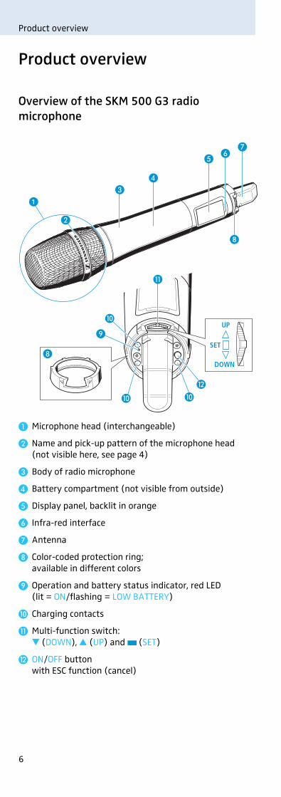
Overview of the SKM 500 G3 radio microphone
� Microphone head (interchangeable)
� Name and pick-up pattern of the microphone head (not visible here, see page 4)
� Body of radio microphone
� Battery compartment (not visible from outside)
� Display panel, backlit in orange
� Infra-red interface
� Antenna
Color-coded protection ring; available in different colors
Operation and battery status indicator, red LED (lit = ON/flashing = LOW BATTERY)
� Charging contacts
� Multi-function switch:� (DOWN), � (UP) and (SET)
ON/OFF button with ESC function (cancel)
��
��
��
�
�
�
�
�

7
Product overview
Overview of the displays
After switch-on, the radio microphone displays thestandard display “Frequency/Name”. For further illustra-tions and examples of the different standard displays, referto page 15.
The display backlighting is automatically reduced afterapprox. 20 seconds.
Display Meaning
� Audio level “AF” Modulation of the radio micro-phone with peak hold function
� Frequency Current transmission frequency
� Name Freely selectable name of the transmitter
� Transmission icon RF signal is being transmitted
� Lock mode icon Lock mode is activated
� “P” (pilot tone) Pilot tone transmission is activated
� “MUTE” Audio signal is muted
� Battery status Charge status:
approx. 100%
approx. 70%
approx. 30%
charge status is critical, the red LOW BATTERY LED is flashing:
MHz542.625ew500 G3
MUTEPAF
� ��
�
�
���
8
Putting the radio microphone into operation
Putting the radio microphone into operation
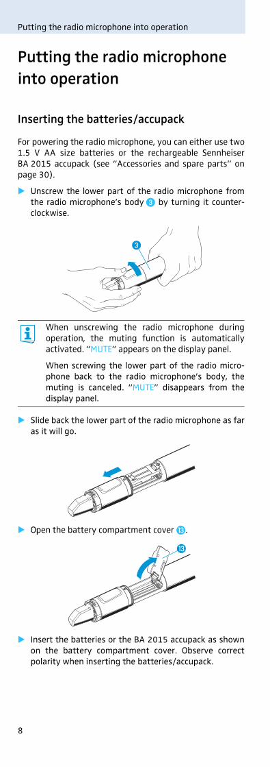
Inserting the batteries/accupack
For powering the radio microphone, you can either use two1.5 V AA size batteries or the rechargeable SennheiserBA 2015 accupack (see “Accessories and spare parts” onpage 30).
� Unscrew the lower part of the radio microphone fromthe radio microphone’s body � by turning it counter-clockwise.
� Slide back the lower part of the radio microphone as faras it will go.
� Open the battery compartment cover �.
� Insert the batteries or the BA 2015 accupack as shownon the battery compartment cover. Observe correctpolarity when inserting the batteries/accupack.
When unscrewing the radio microphone duringoperation, the muting function is automaticallyactivated. “MUTE” appears on the display panel.
When screwing the lower part of the radio micro-phone back to the radio microphone’s body, themuting is canceled. “MUTE” disappears from thedisplay panel.
�
�

9
Putting the radio microphone into operation
� Close the battery compartment cover �.
� Push the battery compartment into the radio micro-phone’s body.
� Screw the lower part of the radio microphone back tothe radio microphone’s body �.
Charging the accupack
To charge the radio microphone with the BA 2015 accupack(see “Accessories and spare parts” on page 30) installed:
� Insert the radio microphone into the LA 2 chargingadapter (see “Accessories and spare parts” on page 30)until it locks into place.
� Plug the LA 2 charging adapter with the inserted radiomicrophone into the L 2015 charger (see “Accessoriesand spare parts” on page 30).
Changing the microphone head
The microphone head � is easy to change.
� Unscrew the microphone head �.
The LA 2 charging adapter and L 2015 charger canonly charge the radio microphone with the BA 2015accupack installed. Standard batteries (primarycells) or individual rechargeable battery cells cannotbe charged in this way.
�
L 2015
LA 2
�
10
Putting the radio microphone into operation
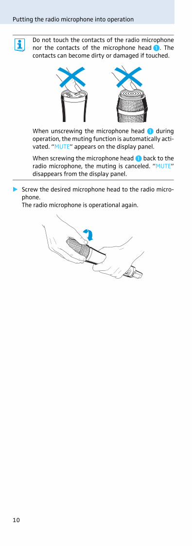
� Screw the desired microphone head to the radio micro-phone.The radio microphone is operational again.
Do not touch the contacts of the radio microphonenor the contacts of the microphone head �. Thecontacts can become dirty or damaged if touched.
When unscrewing the microphone head � duringoperation, the muting function is automatically acti-vated. “MUTE” appears on the display panel.
When screwing the microphone head � back to theradio microphone, the muting is canceled. “MUTE”disappears from the display panel.
11
Putting the radio microphone into operation
Changing the color-coded protection ring
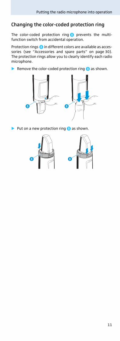
The color-coded protection ring prevents the multi-function switch from accidental operation.
Protection rings in different colors are available as acces-sories (see “Accessories and spare parts” on page 30).The protection rings allow you to clearly identify each radiomicrophone.
� Remove the color-coded protection ring as shown.
� Put on a new protection ring as shown.
12
Using the radio microphone
Using the radio microphone
To establish a transmission link, proceed as follows:
1. Switch the receiver on (see the instruction manual of the receiver).
2. Switch the radio microphone on (see next section).The transmission link is established and the displaybacklighting of the receiver changes from red to orange.
If you cannot establish a transmission link between radiomicrophone and receiver, refer to the chapter “Synchro-nizing the radio microphone with a receiver” on page 26.
Switching the radio microphone on/off
To switch the radio microphone on (online operation):
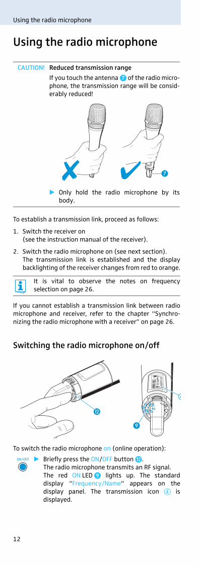
CAUTION! Reduced transmission range
If you touch the antenna � of the radio micro-phone, the transmission range will be consid-erably reduced!
� Only hold the radio microphone by itsbody.
It is vital to observe the notes on frequencyselection on page 26.
� Briefly press the ON/OFF button .The radio microphone transmits an RF signal. The red ON LED lights up. The standarddisplay “Frequency/Name” appears on thedisplay panel. The transmission icon � isdisplayed.
�
�
ON/OFF
13
Using the radio microphone
To switch the radio microphone off:
� If necessary, deactivate the lock mode (see page 14).
To switch the radio microphone on and to deactivate theRF signal on switch-on (offline operation):
To activate the RF signal:
You can switch the radio microphone on and deacti-vate the RF signal on switch-on. For more informa-tion, see next section.
� Keep the ON/OFF button pressed until “OFF”appears on the display panel. The red ON LED goes off and the display panel turns off.
When in the operating menu, pressing the ON/OFF button will cancel your entry (ESC function)and return you to the current standard display.
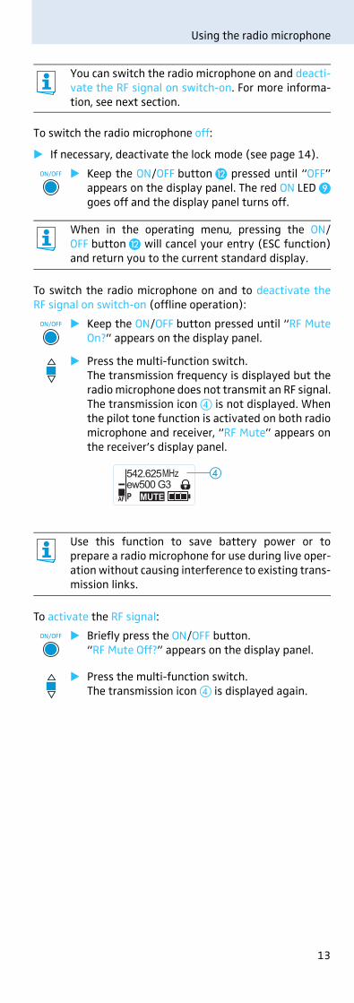
� Keep the ON/OFF button pressed until “RF MuteOn?” appears on the display panel.
� Press the multi-function switch.The transmission frequency is displayed but theradio microphone does not transmit an RF signal.The transmission icon � is not displayed. Whenthe pilot tone function is activated on both radiomicrophone and receiver, “RF Mute” appears onthe receiver’s display panel.
Use this function to save battery power or toprepare a radio microphone for use during live oper-ation without causing interference to existing trans-mission links.
� Briefly press the ON/OFF button.“RF Mute Off?” appears on the display panel.
� Press the multi-function switch.The transmission icon � is displayed again.
ON/OFF
ON/OFF
MHz542.625ew500 G3
MUTEPAF
�
ON/OFF
14
Using the radio microphone
Deactivating the lock mode temporarily
You can activate or deactivate the automatic lock mode viathe “Auto Lock” menu item (see page 22).
If the lock mode is activated, you have to temporarily deac-tivate it In order to be able to operate the radio microphone:
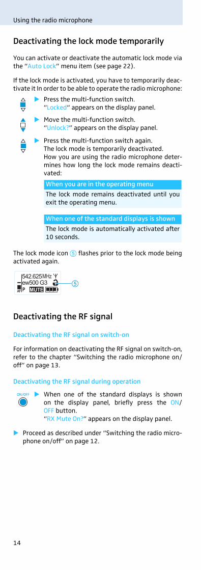
The lock mode icon � flashes prior to the lock mode beingactivated again.
Deactivating the RF signal
Deactivating the RF signal on switch-on
For information on deactivating the RF signal on switch-on,refer to the chapter “Switching the radio microphone on/off” on page 13.
Deactivating the RF signal during operation
� Proceed as described under “Switching the radio micro-phone on/off” on page 12.
� Press the multi-function switch.“Locked“ appears on the display panel.
� Move the multi-function switch.“Unlock?” appears on the display panel.
� Press the multi-function switch again.The lock mode is temporarily deactivated.How you are using the radio microphone deter-mines how long the lock mode remains deacti-vated:
� When one of the standard displays is shownon the display panel, briefly press the ON/OFF button.“RX Mute On?” appears on the display panel.
When you are in the operating menu
The lock mode remains deactivated until youexit the operating menu.
When one of the standard displays is shown
The lock mode is automatically activated after10 seconds.
MHz542.625ew500 G3
MUTEPAF
�
ON/OFF

15
Using the radio microphone
Selecting a standard display
� Move the multi-function switch to select astandard display.
Contents of the display Selectable standard display
“Frequency/Name”
“Frequency bank/Channel/Frequency”
“Name/Frequency bank/Channel”
ew500 G3 MHz542.625
MUTEPAF
MHz542.625B.Ch: 20.30
MUTEPAF
B.Ch: 20.30MUTEPAF
ew500 G3
16
Using the operating menu
Using the operating menu
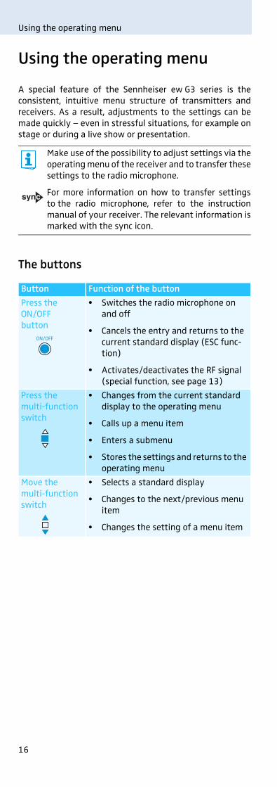
A special feature of the Sennheiser ew G3 series is theconsistent, intuitive menu structure of transmitters andreceivers. As a result, adjustments to the settings can bemade quickly – even in stressful situations, for example onstage or during a live show or presentation.
The buttons
Make use of the possibility to adjust settings via theoperating menu of the receiver and to transfer thesesettings to the radio microphone.
For more information on how to transfer settingsto the radio microphone, refer to the instructionmanual of your receiver. The relevant information ismarked with the sync icon.
Button Function of the button
Press the ON/OFFbutton
• Switches the radio microphone on and off
• Cancels the entry and returns to the current standard display (ESC func-tion)
• Activates/deactivates the RF signal(special function, see page 13)
Press the multi-function switch
• Changes from the current standard display to the operating menu
• Calls up a menu item
• Enters a submenu
• Stores the settings and returns to the operating menu
Move the multi-function switch
• Selects a standard display
• Changes to the next/previous menu item
• Changes the setting of a menu item
ON/OFF
17
Using the operating menu
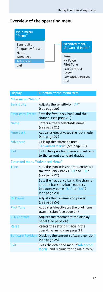
Overview of the operating menu
Display Function of the menu item
Main menu “Menu”
Sensitivity Adjusts the sensitivity “AF” (see page 20)
Frequency Preset Sets the frequency bank and the channel (see page 21)
Name Enters a freely selectable name (see page 21)
Auto Lock Activates/deactivates the lock mode(see page 22)
Advanced Calls up the extended menu “Advanced Menu” (see page 22)
Exit Exits the operating menu and returns to the current standard display
Extended menu “Advanced Menu”
Tune Sets the transmission frequencies for the frequency banks “U1” to “U6” (see page 22)
Sets the frequency bank, the channel and the transmission frequency (frequency banks “U1” to “U6”) (see page 23)
RF Power Adjusts the transmission power(see page 24)
Pilot Tone Activates/deactivates the pilot tone transmission (see page 24)
LCD Contrast Adjusts the contrast of the display panel (see page 24)
Reset Resets the settings made in the operating menu (see page 25)
Software Revision Displays the current software revision(see page 25)
Exit Exits the extended menu “Advanced Menu” and returns to the main menu
Main menu“Menu”
Sensitivity Frequency PresetNameAuto LockAdvanced Exit
TuneRF PowerPilot Tone LCD Contrast ResetSoftware RevisionExit
Extended menu“Advanced Menu”
18
Using the operating menu
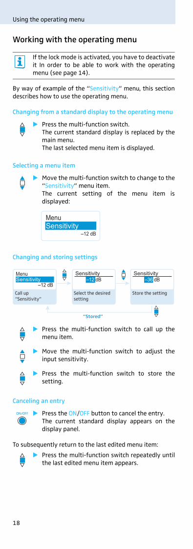
Working with the operating menu
By way of example of the “Sensitivity” menu, this sectiondescribes how to use the operating menu.
Changing from a standard display to the operating menu
Selecting a menu item
Changing and storing settings
Canceling an entry
To subsequently return to the last edited menu item:
If the lock mode is activated, you have to deactivateit In order to be able to work with the operatingmenu (see page 14).
� Press the multi-function switch. The current standard display is replaced by themain menu. The last selected menu item is displayed.
� Move the multi-function switch to change to the“Sensitivity” menu item.The current setting of the menu item isdisplayed:
� Press the multi-function switch to call up themenu item.
� Move the multi-function switch to adjust theinput sensitivity.
� Press the multi-function switch to store thesetting.
� Press the ON/OFF button to cancel the entry.The current standard display appears on thedisplay panel.
� Press the multi-function switch repeatedly untilthe last edited menu item appears.
MenuSensitivity
–12 dB
Menu
–12 dBSensitivity –12 dB
Sensitivity–36 dB
Sensitivity
“Stored”
Call up “Sensitivity”
Select the desired setting
Store the setting
ON/OFF
19
Using the operating menu
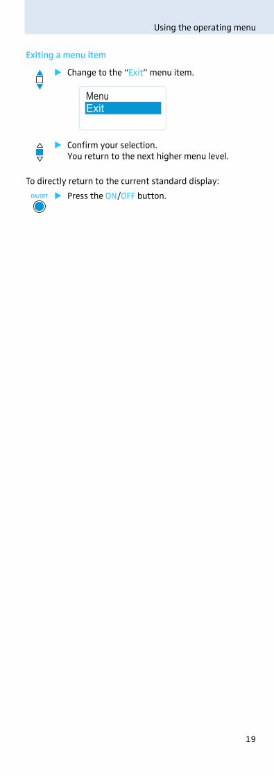
Exiting a menu item
To directly return to the current standard display:
� Change to the “Exit” menu item.
� Confirm your selection.You return to the next higher menu level.
� Press the ON/OFF button.
MenuExit
ON/OFF

20
Adjusting settings via the operating menu
Adjusting settings via the operating menu
The main menu “Menu”
Adjusting the input sensitivity – “Sensitivity”
Adjustment range: 0 to −48 dB, adjustable in steps of 6 dB
Make use of the possibility to adjust settings via theoperating menu of your receiver and to transferthese settings to the radio microphone.
For more information, refer to the instructionmanual of the receiver. The relevant information ismarked with the sync icon.
The audio level display “AF” � always indicates theaudio level, even if the radio microphone is muted,e.g. allowing you to check the adjusted sensitivitybefore live operation.
Input sensitivity is adjusted ... Effect/display
... too high Close talking distances, speakers with loud voices or loud music passages cause overmodulation in the transmission link. The audio level display “AF” � shows full deflection for the duration of the overmodula-tion.
... correctly The audio level display “AF” � shows full deflection only during the loudest passages.
... too low The transmission link is undermodu-lated. This results in a signal with high background noise.
Menu
–12 dBSensitivity –12 dB
Sensitivity–36 dB
Sensitivity
“Stored”
Call up “Sensitivity”
Select the desired setting
Store the setting
MHz542.625B.Ch: 20.30
MUTEAF P
�

21
Adjusting settings via the operating menu
The following figures are a guide to the best settings:
Selecting the frequency bank and the channel manually – “Frequency Preset”
Overview of the frequency banks and channels:
Entering a name – “Name”
Via the “Name” menu, you can enter a freely selectablename (e.g. the name of the performer) for the radio micro-phone.
Transmission situation Sensitivity setting
Loud music/vocals −48 to −18 dB
Presentations −18 to −12 dB
Interviews −12 to 0 dB
When you are in the “Frequency Preset” menu item,the RF signal is deactivated.
Frequency bank Channels Type
“1” to “20” up to 32 per frequency bank
System bank: frequencies are factory-preset
“U1” to “U6” up to 32 per frequency bank
User bank: frequencies are freely selectable
When setting up multi-channel systems, pleaseobserve the following:
Only the factory-preset frequencies within onefrequency bank are intermodulation-free (seepage 26).
Radio microphone and receiver of a transmissionlink have to be set to the same frequency.
� It is vital to observe the notes on frequencyselection on page 26.
Menu
B.Ch: 1. 1B.Ch:
MHz
Frequency PresetFrequency Preset 1. 1 B.Ch:
MHz
Frequency 20. 1
542.625 533.875Call up “Frequency Preset”
Select the frequency bank and confirm
Select the channel; store the setting
“Stored”
Menu
LichaelName
Name NameLichael Michael
“Stored”
Call up “Name” Enter a character and confirm
Enter a character; store the setting
22
Adjusting settings via the operating menu
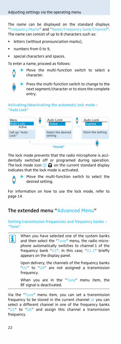
The name can be displayed on the standard displays“Frequency/Name” and “Name/Frequency bank/Channel”.The name can consist of up to 8 characters such as:
• letters (without pronounciation marks),
• numbers from 0 to 9,
• special characters and spaces.
To enter a name, proceed as follows:
Activating/deactivating the automatic lock mode – “Auto Lock“
The lock mode prevents that the radio microphone is acci-dentally switched off or programed during operation.The lock mode icon � on the current standard displayindicates that the lock mode is activated.
For information on how to use the lock mode, refer topage 14.
The extended menu “Advanced Menu”
Setting transmission frequencies and frequency banks – “Tune”
Via the “Tune” menu item, you can set a transmissionfrequency to be stored in the current channel or you canselect a different channel in one of the frequency banks“U1” to “U6” and assign this channel a transmissionfrequency.
� Move the multi-function switch to select acharacter.
� Press the multi-function switch to change to thenext segment/character or to store the completeentry.
� Move the multi-function switch to select thedesired setting.
When you have selected one of the system banksand then select the “Tune” menu, the radio micro-phone automatically switches to channel 1 of thefrequency bank “U1”. In this case, “U1.1” brieflyappears on the display panel.
Upon delivery, the channels of the frequency banks“U1” to “U6” are not assigned a transmissionfrequency.
When you are in the “Tune” menu item, theRF signal is deactivated.
ActiveAuto Lock Active
Auto LockInactive
Auto LockMenu
“Stored”
Call up “Auto Lock”
Select the desired setting
Store the setting
23
Adjusting settings via the operating menu
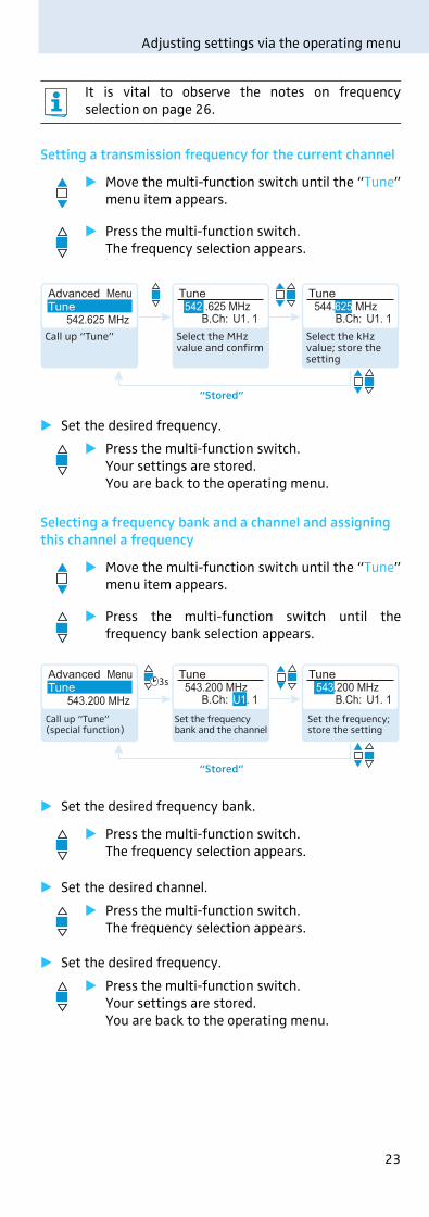
Setting a transmission frequency for the current channel
� Set the desired frequency.
Selecting a frequency bank and a channel and assigning this channel a frequency
� Set the desired frequency bank.
� Set the desired channel.
� Set the desired frequency.
It is vital to observe the notes on frequencyselection on page 26.
� Move the multi-function switch until the “Tune”menu item appears.
� Press the multi-function switch.The frequency selection appears.
� Press the multi-function switch.Your settings are stored. You are back to the operating menu.
� Move the multi-function switch until the “Tune”menu item appears.
� Press the multi-function switch until thefrequency bank selection appears.
� Press the multi-function switch.The frequency selection appears.
� Press the multi-function switch.The frequency selection appears.
� Press the multi-function switch.Your settings are stored.You are back to the operating menu.
542 .625 MHzTune
544.625 MHzB.Ch: U1. 1 B.Ch: U1. 1
TuneAdvanced MenuTune
“Stored”
542.625 MHzSelect the MHz value and confirm
Select the kHz value; store the setting
Call up “Tune”
543.200 MHzTune
B.Ch: U1. 1 B.Ch: U1. 1
TuneAdvanced MenuTune
“Stored”
543.200 MHz543.200 MHz
Set the frequency bank and the channel
Set the frequency; store the setting
Call up “Tune” (special function)

24
Adjusting settings via the operating menu
Adjusting the transmission power – “RF Power”
Via the “RF Power” menu item, you can adjust the transmis-sion power in two steps.
Activating/deactivating the pilot tone transmission – “Pilot Tone”
The radio microphone adds an inaudible signal, known asthe pilot tone, to the transmitted signal. The receiverdetects and evaluates the pilot tone.
The pilot tone supports the receiver’s squelch function(Squelch) and protects against interference due toRF signals from other devices.
Devices of the ew 500 G1 series (generation 1) do notsupport the pilot tone function. Therefore, please observethe following when combining a radio microphone orreceiver of the ew 500 G3 series (generation 3) withdevices from an earlier evolution wireless generation:
Adjusting the contrast of the display panel – “LCD Contrast“
You can adjust the contrast of the display panel in 16 steps.
It is vital to observe the notes on the suppliedfrequency information sheet.
Radio microphone Receiver Make sure to ...
w G3/ w G2 w G3/ w G2 ... activate the pilot tone function on both radio microphone and receiver.
w G3 w G1 ... deactivate the pilot tone function on the ew 500 G3 radio microphone.
w G1 w G3 ... deactivate the pilot tone function on the ew 500 G3 receiver.
Advanced MenuRF Power Standard
RF PowerLow
RF Power
“Stored”
Call up “RF Power”
Select the desired setting
Store the setting
NameAdvanced MenuPilot Tone Active
Pilot ToneInactive
Pilot Tone
“Stored”
Call up “Pilot Tone”
Select the desired setting
Store the setting

25
Adjusting settings via the operating menu
Resetting the settings made in the operating menu – “Reset”
When resetting the settings made in the operating menu,only the selected settings for the pilot tone and for thefrequency banks “U1” to “U6” remain unchanged.
For an overview of the factory-preset default settings, referto the supplied frequency information sheet.
Displaying the software revision – “Software Revision”
You can display the current software revision of the radiomicrophone.
� For information on software updates, visit theSKM 500 G3 product page at www.sennheiser.com.
Select the desired setting; apply the setting
Call up “Reset”
Advanced MenuReset Yes
Reset
“Stored”

26
Synchronizing the radio microphone with a receiver
Synchronizing the radio microphone with a receiver
When synchronizing the radio microphone with a receiver,please observe the following:
Synchronizing the radio microphone with the receiver – individual operation
Upon delivery, the radio microphone and the receiver aresynchronized with each other.
If, however, you cannot establish a transmission linkbetween radio microphone and receiver, you have tosynchronize the channels of the devices.
For information on automatic synchronization of the radiomicrophone with the receiver (individual operation), referto the instruction manual of the receiver. This informationis marked with the icon.
Alternatively, you can set the channel on the radio micro-phone manually:
� Make sure that you set the radio microphone to thesame frequency bank and the same channel as thereceiver (see page 21).
If you still cannot establish a transmission link, refer to thechapter “If a problem occurs ...” on page 29.
Synchronizing radio microphones with receivers – multi-channel operation
Combined with ew 500 G3 receivers, ew 500 G3 radiomicrophones can form transmission links that can be usedin multi-channel systems.
For information on automatic synchronization of radiomicrophones with receivers (multi-channel operation),refer to the instruction manual of your receiver.
For more information on multi-channel operation, visit theSKM 500 G3 product page at www.sennheiser.com.
� Only use a transmitter and a receiver from thesame frequency range (see the type plate on thetransmitter and the receiver).
� Make sure that the desired frequencies are listedin the enclosed frequency information sheet.
� Make sure that the desired frequencies areapproved and legal in your country and, if neces-sary, apply for an operating license.

27
Cleaning the radio microphone
Cleaning the radio microphone
� Use a cloth to clean the radio microphone from time totime.
� Do not use any solvents or cleansing agents.
To clean the sound inlet basket of the microphone head(MMD 935-1, MMD 945-1):
� Unscrew the upper sound inlet basket from themicrophone head by turning it counterclockwise (seediagram).
� Remove the foam insert.
� To clean the sound inlet basket:
– Use a cloth to clean the upper sound inlet basket fromthe inside and outside.OR
– Scrub with a brush and rinse with clear water.
� If necessary, clean the foam insert with a mild detergentor replace the foam insert.
� Dry the upper sound inlet basket.
� Dry the foam insert.
� Reinsert the foam insert.
� Replace the sound inlet basket on the microphone headand screw it tight.
You should also clean the contact rings of the microphonehead from time to time:
� Wipe the contact rings of the microphone head with acloth.
CAUTION! Liquids can damage the electronics of theradio microphone!
Liquids entering the housing of the devicecan cause a short-circuit and damage theelectronics.
� Keep all liquids away from the radio micro-phone.
CAUTION! Liquids will damage the microphone module!
Liquids will damage the microphone module.
� Only clean the upper sound inlet basket.
For information on cleaning the MMK 965-1 micro-phone head, refer to its instruction manual.

28
Recommendations and tips
Recommendations and tips
... for optimum sound
• Hold the radio microphone in the middle of the micro-phone body. Holding it close to the sound inlet basketwill influence the radio microphone’s pick-up pattern.
• You can vary the bass reproduction by increasing/decreasing the talking distance.
• For best results, make sure that the sensitivity iscorrectly adjusted.
... for optimum reception
• Transmission range depends to a large extent on loca-tion and can vary from about 10 m to about 150 m.There should be a “free line of sight” between trans-mitting and receiving antennas.
• To avoid overloading the receiver, observe a minimumdistance of 5 m between transmitting and receivingantennas.
• Only hold the radio microphone by its body. If youtouch the antenna of the radio microphone, the trans-mission range will be considerably reduced.
... for multi-channel operation
• For multi-channel operation, you should only use thechannels within one frequency bank. Each of thefrequency banks “1” to “20” accommodates factory-preset frequencies which are intermodulation-free.
• When using several transmitters simultaneously,interference can be avoided by maintaining aminimum distance of 20 cm between two transmitters.

29
If a problem occurs ...
If a problem occurs ...
If a problem occurs that is not listed in the above table or ifthe problem cannot be solved with the proposed solutions,please contact your local Sennheiser partner for assistance.
To find a Sennheiser partner in your country, search atwww.sennheiser.com under “Service & Support”.
Problem Possible cause Possible solution
Radio micro-phone cannot be operated, “Locked” appears on the display panel
Lock mode is activated
Deactivate the lock mode (see page 14).
No opera-tion indica-tion
Batteries are flat or accupack is flat
Replace the batteries or recharge the accupack (see page 8).
No RF signal at the receiver
Radio microphone and receiver are not on the same channel
Set the radio micro-phone to the same channel as the receiver.
Synchronize the radio microphone with the receiver (see page 16).
Transmission range is exceeded
Reduce the distance between radio micro-phone and receiving antennas.
Increase the trans-mission power (see page 24).
RF signal is deactivated (“RF Mute“)
Activate the RF signal (see page 14).
RF signal available, no audio signal,“MUTE” appears on the display panel
Receiver’s squelch threshold is adjusted too high
Reduce the squelch threshold setting on the receiver.
Radio microphone doesn’t transmit a pilot tone
Activate or deacti-vate the pilot tone transmission (see page 24).
Audio signal has a high level of background noise or audio signal is distorted
Radio microphone’s sensitivity is adjusted too low/too high
Adjust the input sensitivity (see page 20).

30
Accessories and spare parts
Accessories and spare parts
The following accessories are available from your specialistdealer:
Cat. No. Product name and description
009950 BA 2015 accupack
009828 L 2015 charger
503162 LA 2 charging adapter
503168 CC 3 system case
004839 MZW 1 wind and pop shield
002155 MZQ 1 microphone clamp
Microphone heads
502577 MMD 935-1 microphone head,dynamic, cardioid
502579 MMD 945-1 microphone head,dynamic, super-cardioid
502575 MMD 835-1 microphone head,dynamic, cardioid
502576 MMD 845-1 microphone head,dynamic, super-cardioid
501581 MME 865-1 microphone head,condenser, super-cardioid
502582 MMK 965-1 BK microphone head, color blackexternally polarized dual diaphragm condenser microphone, cardioid/super-cardioid (switch-able)
502583 MMK 965-1 BL microphone head, color blueexternally polarized dual diaphragm condenser microphone, cardioid/super-cardioid (switch-able)
502584 MMK 965-1 NI microphone head, color nickelexternally polarized dual diaphragm condenser microphone, cardioid/super-cardioid (switch-able)
31
Specifications
Specifications
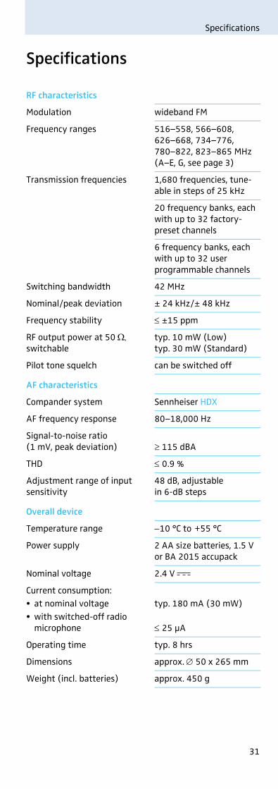
RF characteristics
Modulation wideband FM
Frequency ranges 516–558, 566–608, 626–668, 734–776, 780–822, 823–865 MHz(A–E, G, see page 3)
Transmission frequencies 1,680 frequencies, tune-able in steps of 25 kHz
20 frequency banks, each with up to 32 factory-preset channels
6 frequency banks, each with up to 32 user programmable channels
Switching bandwidth 42 MHz
Nominal/peak deviation ± 24 kHz/± 48 kHz
Frequency stability ≤ ±15 ppm
RF output power at 50 Ω,switchable
typ. 10 mW (Low)typ. 30 mW (Standard)
Pilot tone squelch can be switched off
AF characteristics
Compander system Sennheiser HDX
AF frequency response 80–18,000 Hz
Signal-to-noise ratio(1 mV, peak deviation) ≥ 115 dBA
THD ≤ 0.9 %
Adjustment range of input sensitivity
48 dB, adjustable in 6-dB steps
Overall device
Temperature range −10 °C to +55 °C
Power supply 2 AA size batteries, 1.5 V or BA 2015 accupack
Nominal voltage 2.4 V
Current consumption:• at nominal voltage• with switched-off radio
microphone
typ. 180 mA (30 mW)
≤ 25 μA
Operating time typ. 8 hrs
Dimensions approx. ∅ 50 x 265 mm
Weight (incl. batteries) approx. 450 g
32
Specifications
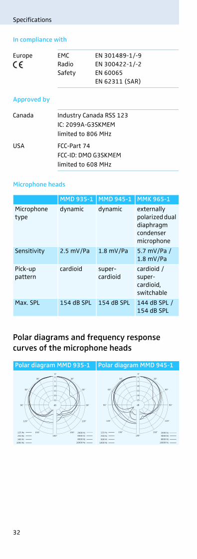
In compliance with
Approved by
Microphone heads
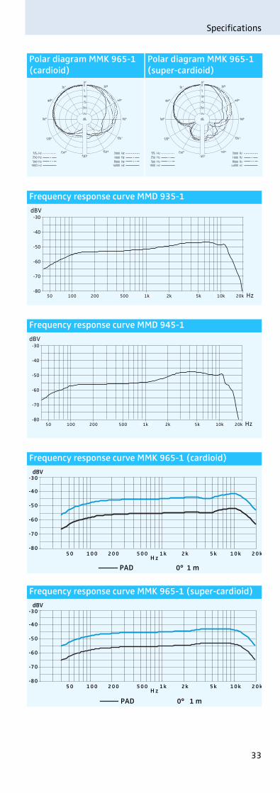
Polar diagrams and frequency response curves of the microphone heads
Europe EMC EN 301489-1/-9Radio EN 300422-1/-2Safety EN 60065
EN 62311 (SAR)
Canada Industry Canada RSS 123IC: 2099A-G3SKMEMlimited to 806 MHz
USA FCC-Part 74FCC-ID: DMO G3SKMEMlimited to 608 MHz
MMD 935-1 MMD 945-1 MMK 965-1
Microphone type
dynamic dynamic externally polarized dual diaphragm condenser microphone
Sensitivity 2.5 mV/Pa 1.8 mV/Pa 5.7 mV/Pa /1.8 mV/Pa
Pick-up pattern
cardioid super-cardioid
cardioid / super-cardioid,switchable
Max. SPL 154 dB SPL 154 dB SPL 144 dB SPL / 154 dB SPL
Polar diagram MMD 935-1 Polar diagram MMD 945-1
0
5
10
15
20
25
dB
30° 30°
60°60°
90° 90°
120°
150°
120°
150°
0°
180°125 Hz
250 Hz
500 Hz
1000 Hz
2000 Hz
4000 Hz
8000 Hz
16000 Hz
0
5
10
15
20
25
dB
30° 30°
60°60°
90° 90°
120°
150°
120°
150°
0°
180°125 Hz
250 Hz
500 Hz
1000 Hz
2000 Hz
4000 Hz
8000 Hz
16000 Hz
33
Specifications
Polar diagram MMK 965-1 (cardioid)
Polar diagram MMK 965-1 (super-cardioid)
Frequency response curve MMD 935-1
Frequency response curve MMD 945-1
Frequency response curve MMK 965-1 (cardioid)
Frequency response curve MMK 965-1 (super-cardioid)
Hz100 1.000 10.000
dBV-30
-40
-50
-60
-70
-8050 100 200 500 1k 2k 5k 10k 20k
Hz100 1.000 10.000
dBV-30
-40
-50
-60
-70
-8050 100 200 500 1k 2k 5k 10k 20k
H z
dBV-30
-40
-50
-60
-70
-805 0 1 0 0 2 0 0 5 0 0 1 k 2 k 5 k 1 0 k 2 0 k
0° 1 mPAD
H z
dBV
0° 1 m
-30
-40
-50
-60
-70
-805 0 1 0 0 2 0 0 5 0 0 1 k 2 k 5 k 1 0 k 2 0 k
PAD
36
Index
Index
AAccupack
charging 9inserting 8
Activating/deactivatinglock mode (Auto Lock) 22pilot tone 24
Adjustingcontrast (LCD Contrast) 24input sensitivity (Sensitivity) 20transmission power 24
Advanced Menu (extended menu)overview 17settings 22
AF (audio level) 7Auto Lock (activating/deactivating the lock mode) 22BBatteries, inserting 8Buttons (function of the ~) 16CChannel
assigning a frequency 23overview 3selecting (Frequency Preset) 21selecting (Tune) 22
Chargingaccupack 9battery status display 7
Cleaning (radio microphone) 27Color-coded protection ring, changing 11DDeactivating
lock mode temporarily 14Displays
adjusting the contrast (LCD Contrast) 24charge status 7overview 7standard displays 15
FFactory default settings (resetting the settings in the
operating menu) 25Frequency
preset frequencies 3~ ranges 3selecting ~ presets 21setting the transmission ~ 22
Frequency bankoverview 3selecting (Frequency Preset) 21~ system 3
Frequency Preset (selecting a frequency bank/channel) 21
IInfra-red transmission 26Inserting (batteries/accupack) 8LLCD Contrast (contrast of the display panel) 24
37
Index
Lock modeactivating/deactivating (Auto Lock) 22deactivating temporarily 14
Locked (lock mode activated) 14MMenu (main menu)
overview 17settings 20
Microphone headschanging 9changing the color-coded protection ring 11overview 4pick-up patterns 4polar diagrams/frequency response curves 32suitable ~ 4
Modulation (input sensitivity/adjusting the sensitivity) 20
Multi-channel operation 26NName (entering a name) 21OOffline operation (RF signal deactivated) 13Online operation (RF signal activated) 12PPilot tone
activating/deactivating 24transmission 24
RRadio microphone
cleaning 27resetting (Reset) 25switching on/off 12synchronizing with receiver 26
Reset (resetting the settings in the operating menu) 25RF Mute On/Off (activating/deactivating the RF signal) 13RF Power (adjusting the transmission power) 24RF signal
activating (online operation) 12deactivating (during operation) 14deactivating (offline operation) 13
SSelecting (Tune) 23Sensitivity (adjusting the input sensitivity) 20Setting up
multi-channel system 26transmission link 26
Synchronizing (radio microphone/receiver) 26TTransmission frequency
selecting (Frequency Preset) 21setting (Tune) 22
Transmission link, establishing 26Transmission power, optimizing 28Troubleshooting 29Tune (setting a transmission frequency) 22UUnlock (deactivating the lock mode) 14Using
operating menu 18radio microphone 12

Sennheiser electronic GmbH & Co. KGAm Labor 1, 30900 Wedemark, Germanywww.sennheiser.com
Publ. 12/16 529673
C
M
Y
CM
MY
CY
CMY
K
Top Related