


Languages
Pages
Legal


Abteilung Unternehmenskommunikation Kronprinzenstraße 37 45128 Essen Telefon 0201/178-0 Fax 0201/178-1425 E-mail: [email protected],
000-
2-9,
2012
B 229
B 51
6
B 229
Hev
e
Com
pens
atin
gre
serv
oir
Möh
ne
Mai
npo
wer
stat
ion
Seco
ndar
ypo
wer
sta
tion
Flor
a an
d fa
una
habi
tat
"Hev
earm
des
Möh
nese
es"
Flor
a an
d fa
una
habi
tat
"Möh
neau
eVö
llingh
ause
n"
Flor
a an
d fa
una
habi
tat /
Wal
dres
erva
t"B
reite
nbru
ch/N
euha
us"
Brün
ings
en
Gün
neW
estri
chKö
rbec
ke
Del
ecke
Körb
ecke
rbr
idge
Del
ecke
rbr
idge
Mas
onry
dam
Soes
ter B
örde
Völlin
ghau
sen
Hev
e up
stre
am b
asin
St. M
eino
lfH
eve
upst
ream
dam
Südr
andw
eg
Möh
ne
upst
ream
bas
in
Stoc
kum
erda
mW
amel
Stoc
kum
Arns
berg
er W
ald
Möh
ne re
serv
oir
Flor
a an
d fa
una
habi
tat
„Kle
ine
Schm
alen
aue-
Hev
esee
“
Site Map Möhne Reservoir
Div
ing
spot
s (d
ivin
g fe
es a
pply
)
Publ
ic b
oat a
cces
s
(boa
t slip
)
Boat
and
mot
orbo
at li
cens
ing
office
(fo
r mor
e in
form
atio
n, v
isit
ww
w.ru
hrve
rban
d.de
)Sw
imm
ing
area
Lake
shor
e be
ach
Ferr
y do
ck

Möhne Reservoir
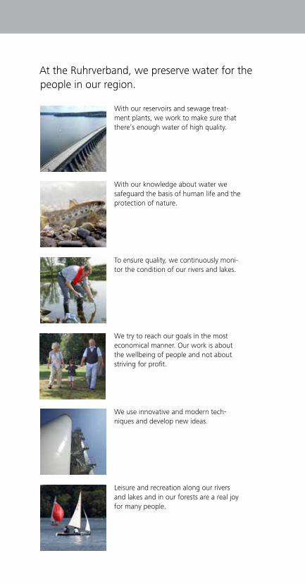
At the Ruhrverband, we preserve water for the people in our region.
With our reservoirs and sewage treat-ment plants, we work to make sure that there’s enough water of high quality.
With our knowledge about water we safeguard the basis of human life and the protection of nature.
To ensure quality, we continuously moni-tor the condition of our rivers and lakes.
We try to reach our goals in the most economical manner. Our work is about the wellbeing of people and not about striving for profit.
We use innovative and modern tech-niques and develop new ideas.
Leisure and recreation along our rivers and lakes and in our forests are a real joy for many people.

Reservoirs ensure water supply
The Ruhr area conurbation’s water supply is primarily ensured by abstracting water from the Ruhr, a relatively small highland river. As a result of seasonal fluctuations in water regimen and water export to neighbouring river basins, reservoirs are needed to ensure the water demand is met continuously. To this end, the Ruhrverband operates a system of centrally controlled reservoirs.
During periods of high runoff, the reservoirs store water to feed the rivers whenever needed. Thus, the Ruhrverband’s primary task is not the immediate supply of drinking and service water to the area’s inhabitants and industry, but ensuring water supply by maintaining minimum runoff levels in the River Ruhr.
2/3
The Möhne Reservoir has the largest surface area of all the Ruhrverband’s reservoirs.
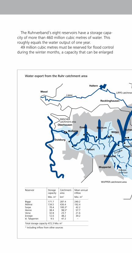
The Ruhrverband’s eight reservoirs have a storage capa-city of more than 460 million cubic metres of water. This roughly equals the water output of one year.
49 million cubic metres must be reserved for flood control during the winter months, a capacity that can be enlarged
Reservoir Storage capacity
Mio. m3
Catchment- area
km2
Mean annual inflow
Mio. m3
Bigge Möhne Sorpe Henne Verse Ennepe kl. Talsperren
171.7 134.5 70.4 38.4 32.8 12.6 9.5
287.4 436.4 100.3* 98,5* 23.7 48.2 47.2
240.2 192.4 42.2 57.7 21.6 39.2 –
Total storage capacity 472.3 Mio. m3
* including inflow from other sources
Reservoir Storagecapacity
Mio. m3
Mean annualinflow
Mio. m3
Catchmentarea
km2
BiggeMöhneSorpeHenneVerseEnnepesmall reservoirs
171.7134.5 70.4 38.4 32.8 12.6 9.5
287.4436.4100.3* 98.5* 23.7 48.2 47.2
240.2192.4 42.2 57.7 21.6 39.2 -
Total storage capacity 472.3 Mio. m
* including inflow from other sources
3
Wuppertal
OberhausenDortmund
Recklinghausen
Haltern
Wesel
Hamm
Soest
Lippe
Lippe
Röhr
WittenRuhr
Möhne
Arnsberg
Brilon
Ruhr
Ruhr
LenneSchmallenberg
Wenne
Olpe
Bigg
e
PlettenbergLüden-scheid
Altena
Hönne
Iserlohn
Ruhr Menden
LenneVolm
e
Hagen
EnnepeVelbert
Duisburg
Rhine
Attendorn
MülheimBochumEssen
Ennepetal
Schwerte
waterworks
WUPPER catchment area
EMSCHERcatchment area
LIPPE catchment area
EMS catchment area
Möhne reservoir
Biggereservoir
Sorpe reservoir
Ennepereservoir
Henne reservoir
Versetal reservoir
Ahausenimpoudinglake
Fürwigge reservoir
Meschede
Neger
Water export from the Ruhr catchment area
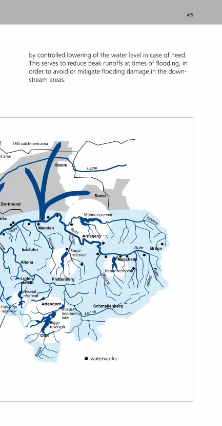
by controlled lowering of the water level in case of need. This serves to reduce peak runoffs at times of flooding, in order to avoid or mitigate flooding damage in the down-stream areas.
Reservoir Storagecapacity
Mio. m3
Mean annualinflow
Mio. m3
Catchmentarea
km2
BiggeMöhneSorpeHenneVerseEnnepesmall reservoirs
171.7134.5 70.4 38.4 32.8 12.6 9.5
287.4436.4100.3* 98.5* 23.7 48.2 47.2
240.2192.4 42.2 57.7 21.6 39.2 -
Total storage capacity 472.3 Mio. m
* including inflow from other sources
3
Wuppertal
OberhausenDortmund
Recklinghausen
Haltern
Wesel
Hamm
Soest
Lippe
Lippe
Röhr
WittenRuhr
Möhne
Arnsberg
Brilon
Ruhr
Ruhr
LenneSchmallenberg
Wenne
Olpe
Bigg
e
PlettenbergLüden-scheid
Altena
Hönne
Iserlohn
Ruhr MendenLenne
Volme
Hagen
EnnepeVelbert
Duisburg
Rhine
Attendorn
MülheimBochumEssen
Ennepetal
Schwerte
waterworks
WUPPER catchment area
EMSCHERcatchment area
LIPPE catchment area
EMS catchment area
Möhne reservoir
Biggereservoir
Sorpe reservoir
Ennepereservoir
Henne reservoir
Versetal reservoir
Ahausenimpoudinglake
Fürwigge reservoir
Meschede
Neger
4/5
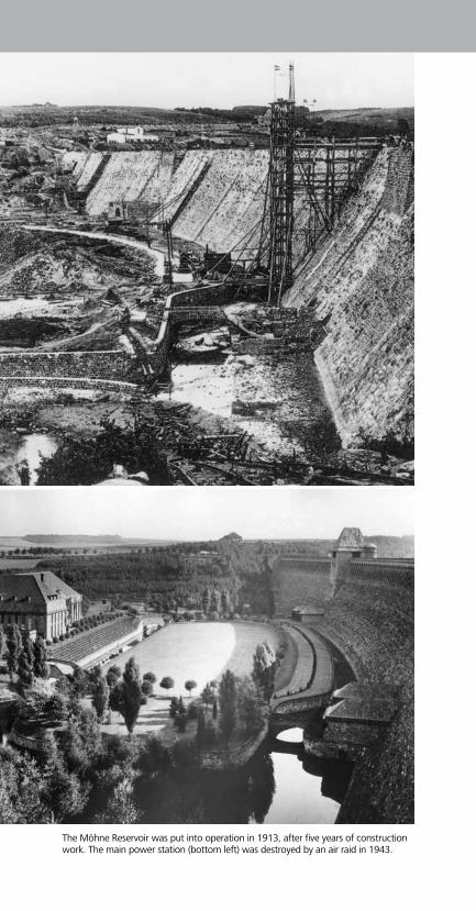
The Möhne Reservoir was put into operation in 1913, after five years of construction work. The main power station (bottom left) was destroyed by an air raid in 1943.

6/7
Construction of the Möhne Reservoir
The Möhne Reservoir used to be one of the largest reser- voirs in Europe. It was put into operation in 1913, after merely five years of construction work. It was financed and constructed by the then Ruhrtalsperrenverein (Ruhr Reservoir Association), which was transformed to an entity under public law in 1913 and merged with the Ruhrver-band in 1990.
The Möhne Reservoir used to be the backbone of the Ruhr area’s water supply and still accounts for 28 percent of total storage capacity, thus making an essential contri-bution to controlling the River Ruhr’s runoff.
It was engineered by the then Regierungsbaumeister (state architect) Ernst Link. Franz Brantzky, a leading Rhenish architect of his time, won the competition for architectural design of the dam. Parts of the Möhne Reservoir’s dam are today listed as a historic monument.
The masonry dam with its slightly arched shape is made of quarry stones. It is 650 metres long, up to 40 metres high and can hold up to 134.5 million cubic metres of water. In the dam’s upstream area, i.e. where the rivers Möhne and Heve join the reservoir, two upstream basins were constructed. Their water level is kept at a constant level independently of the main reservoir, thus reducing the inflow of sediment and nutrients to the main reservoir and improving the living conditions for flora and fauna in the inflow areas.
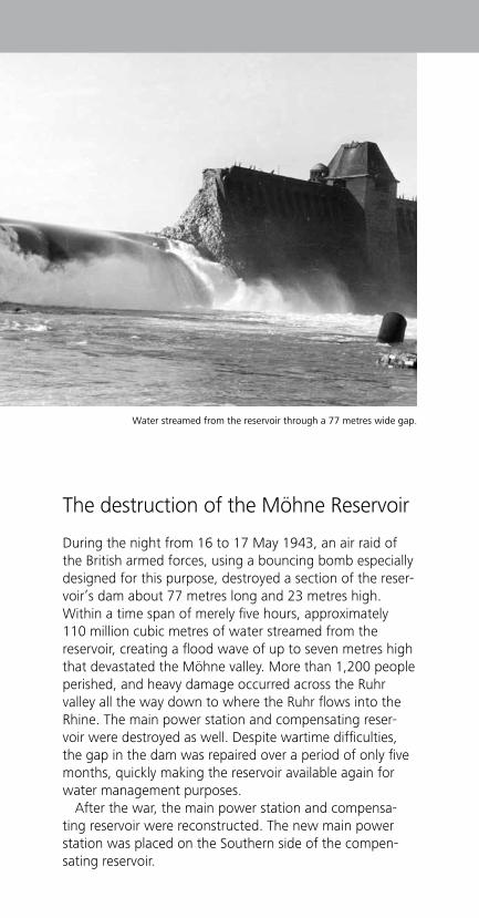
The destruction of the Möhne Reservoir
During the night from 16 to 17 May 1943, an air raid of the British armed forces, using a bouncing bomb especially designed for this purpose, destroyed a section of the reser- voir’s dam about 77 metres long and 23 metres high. Within a time span of merely five hours, approximately 110 million cubic metres of water streamed from the reservoir, creating a flood wave of up to seven metres high that devastated the Möhne valley. More than 1,200 people perished, and heavy damage occurred across the Ruhr valley all the way down to where the Ruhr flows into the Rhine. The main power station and compensating reser-voir were destroyed as well. Despite wartime difficulties, the gap in the dam was repaired over a period of only five months, quickly making the reservoir available again for water management purposes.
After the war, the main power station and compensa-ting reservoir were reconstructed. The new main power station was placed on the Southern side of the compen- sating reservoir.
Water streamed from the reservoir through a 77 metres wide gap.
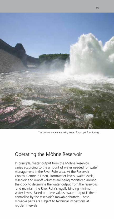
Operating the Möhne Reservoir
In principle, water output from the Möhne Reservoir varies according to the amount of water needed for water management in the River Ruhr area. At the Reservoir Control Centre in Essen, stormwater levels, water levels, reservoir and runoff volumes are being monitored around the clock to determine the water output from the reservoirs and maintain the River Ruhr’s legally binding minimum water levels. Based on these values, water output is then controlled by the reservoir’s movable shutters. These movable parts are subject to technical inspections at regular intervals.
8/9
The bottom outlets are being tested for proper functioning.

In order to preserve the site, it is essential to carry out constant maintenance work and repair even minor dama- ges. Moreover, the areas most frequented by visitors (such as the dam, surrounding paths and shore areas) must be maintained, and the condition of the reservoir’s entire structure must be assessed. As part of a comprehensive measuring programme (e.g. a seepage control system), specific parameters for assessing the site’s structural and operational safety have been established and are measured at regular intervals.
In addition, exact measurements of the masonry dam’s surface area are carried out at larger intervals, in order to be able to recognise possible changes at an early stage.
The reservoir’s water quality is subject to regular controls by the men and women at the Ruhrverband’s laboratory, based on biological and chemical parameters and carried out at different depths.
As a result of the manifold tasks connected with opera-ting a reservoir, we employ specialists with a variety of different job profiles.
View of the Reservoir Control Centre (left), cleaning of the masonry dam (right).

The technology of the Möhne Reservoir
The Möhne Reservoir consists of a gravity dam built in accordance with the principles developed by Professor Otto Intze, a pioneer of German dam engineering. Put simply, its cross section has a triangular shape, commen- surate with water pressure. A triangular wedge made of clay and loam, named “Intze wedge“ after its inventor, is placed in front of the dam’s lower third to provide additio-nal protection in the area with the highest water pressure. The dam’s arched shape is designed to prevent pressure resulting from temperature changes from affecting the massive construction.
10/11
The masonry dam was built with quarry stones.

During normal operation, the water passes through the main power station’s water conduit and from there to the compensating reservoir. At the main power station, the water’s energy is transformed into electricity, supplying approximately 3,000 households with environmentally friendly and climate neutral energy. The dam’s bottom outlets are used only in times of extraordinarily high inflow or a blackout of the main power station. There are two bottom outlet units with two independent outlets each. Each outlet has three shutter elements: two consecutive bottom gates inside the gate towers, and a third gate in the gate houses. The outer gate houses are equipped with circular valves, and the inner gate houses with flat side valves. In contrast to the other shutters, water output through the circular valves can be adjusted infinitely.
If the reservoir is full and the water inflow from the River Möhne exceeds the bottom outlets’ capacity, the surplus water is evacuated via the flood spillways. At the top of the masonry dam, 105 openings over a total length of 262.5 metres serve as flood spillways. The dam’s down-stream side has a rough surface with protruding rocks to effect partial energy dissipation of the overflowing water. The remainder of the energy is dissipated in the compensa-ting reservoir, which serves as a stilling basin.
Cross section of a bottom outlet unit
Compensating reservoir
Circular valve
Gate valve - oval type
Conical jet
Bottom outlet conduit
Axisinspection tunnel
Intze wedge
Bottom gates
0 5 10 m
Trash rack
Longitudinal section of a bottom outlet
Bottom gates
Gate tower
Circular valve
Bottom outlet conduit
Masonry tower
Gate house
Trash rackIntze wedge
Inspection tunnel
Full supply level +213,74 m above sea level
Compensating reservoir+183,60 m above sea level
With flooded spillways, the massive masonry dam offers an impressive sight.
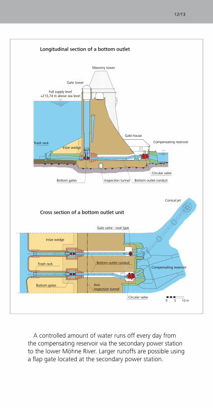
Cross section of a bottom outlet unit
Compensating reservoir
Circular valve
Gate valve - oval type
Conical jet
Bottom outlet conduit
Axisinspection tunnel
Intze wedge
Bottom gates
0 5 10 m
Trash rack
Longitudinal section of a bottom outlet
Bottom gates
Gate tower
Circular valve
Bottom outlet conduit
Masonry tower
Gate house
Trash rackIntze wedge
Inspection tunnel
Full supply level +213,74 m above sea level
Compensating reservoir+183,60 m above sea level
A controlled amount of water runs off every day from the compensating reservoir via the secondary power station to the lower Möhne River. Larger runoffs are possible using a flap gate located at the secondary power station.
12/13
Cross section of a bottom outlet unit
Longitudinal section of a bottom outlet

Top view of the masonry dam
View of the masonry dam
Cascade
Flood spillways
Masonry tower
Cascade
Cascade
Axis access tunnel
Gate houses
Gate houses
Main reservoir
Axis inspection tunnel
Masonry tower
Bottom outlets
Bottom outletsPowerstation line
Main power station
Compensating reservoir
Compensating reservoir
Gate tower
Gate tower
Gate tower
Conical jet
0 50 100 m
View of the masonry dam
Top view of the masonry dam

Top view of the masonry dam
View of the masonry dam
Cascade
Flood spillways
Masonry tower
Cascade
Cascade
Axis access tunnel
Gate houses
Gate houses
Main reservoir
Axis inspection tunnel
Masonry tower
Bottom outlets
Bottom outletsPowerstation line
Main power station
Compensating reservoir
Compensating reservoir
Gate tower
Gate tower
Gate tower
Conical jet
0 50 100 m
14/15
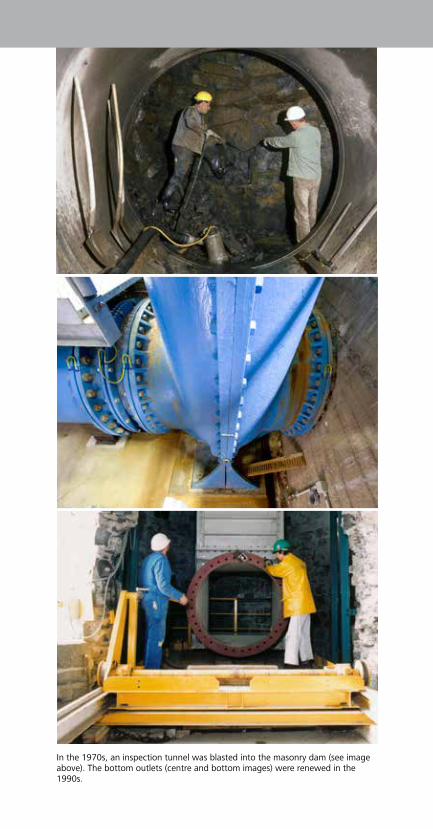
In the 1970s, an inspection tunnel was blasted into the masonry dam (see image above). The bottom outlets (centre and bottom images) were renewed in the 1990s.
16/17
After decades of operating the reservoir, it became appa- rent that the masonry dam was subject to ever increasing seepage, as a result of aging, weathering and war damage. Similar alterations were observed underneath the masonry dam as well. In 1970, a comprehensive inspection clearly showed that major restoration measures were necessary.
Work began by driving a maintenance, drainage and inspection tunnel into the transition zone between the masonry structure and the soil. The tunnel was blasted while normal reservoir operations continued. From the tunnel and the dam’s crest, the dam’s structure and the soil beneath were then proofed, thus reducing seepage to a non-hazardous level. In the process, inspection and drainage boreholes were drilled, allowing for regular moni-toring of seepage.
In the 1990s, the outlet units, which were then 80 years old, were replaced, and the gate towers were proofed. The bottom outlets were replaced entirely. In addition, a comprehensive restoration of the masonry dam’s dama- ged, weathered downstream surface (approx. 20,000 square metres) was carried out.
The restoration of the masonry dam and operational facilities

Nature around the Möhne Reservoir
Many areas around the reservoir are protected under European and national law. The Möhne Reservoir’s entire water surface serves as a resting and breeding habitat for migratory birds and has therefore been listed as a bird sanctuary. Almost the entire Heve river arm has been listed as a nature reserve, and the Heve upstream reservoir is subject to special protection as a European nature heri-tage site.
Compared with other forms of vegetation, forests are best adapted to absorb high precipitation levels, thus helping to reduce flooding damage. Moreover, they reduce ground erosion, and groundwater infiltration cleans the stormwater. As a result, the majority of the forests adjacent to the Möhne Reservoir are a property of the Ruhrverband. They are managed in harmony with nature by our own personnel, in order to guarantee maxi-mum protection of the Reservoir.
As the water level of reservoirs fluctuates over prolonged periods of time, shore vegetation is limited. The unprotec-
ted, steep embankments are eroded by wave action. To prevent this, more than half of the Möhne Reservoir’s shore surface has been fortified with stone fillings, pavings or shore walls. Preferably, today such fortifications are constructed in accordance with soil bioengineering prin-ciples.
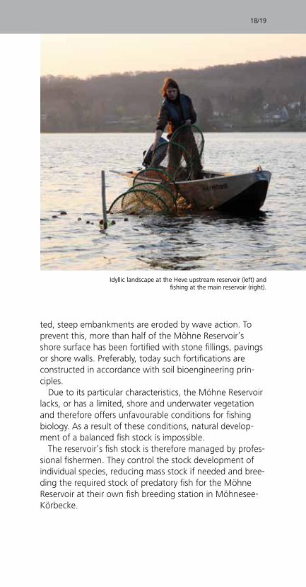
Due to its particular characteristics, the Möhne Reservoir lacks, or has a limited, shore and underwater vegetation and therefore offers unfavourable conditions for fishing biology. As a result of these conditions, natural develop-ment of a balanced fish stock is impossible.
The reservoir’s fish stock is therefore managed by profes-sional fishermen. They control the stock development of individual species, reducing mass stock if needed and bree-ding the required stock of predatory fish for the Möhne Reservoir at their own fish breeding station in Möhnesee-Körbecke.
18/19
Idyllic landscape at the Heve upstream reservoir (left) and fishing at the main reservoir (right).
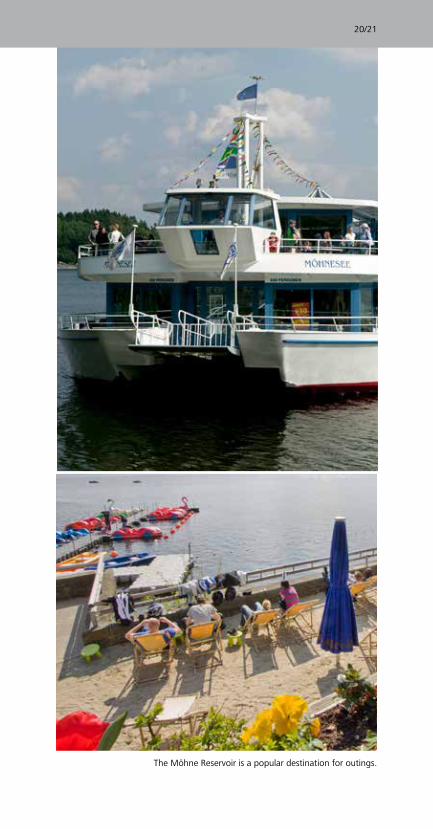
Thanks to its attractive location between the Haar Moun-tains to the North and the Arnsberg Forest Nature Park to the South, as well at its close proximity to the Ruhr area conurbation, the Möhne Reservoir serves as an important recreation area. This makes it a popular destination for outings, not least because it offers numerous possibilities for leisure activities.
In order to reconcile water management, ecological and recreational needs, certain rules are required. Those looking for leisure and recreation are requested to respect these rules, which are indicated on information boards around the reservoir and on the Internet. Swimming, fishing and diving is authorised in designated areas, as well as sailing, surfing and boating, including the use of electric motor boats in accordance with the applicable rules for leisure activities. Interested visitors can tour the reservoir by ferryboat.
Leisure activities at the Möhne Reservoir are coordinated by the company Touristik GmbH Möhnesee. The Ruhr- verband is actively involved in promoting leisure activities around and on the lake as long as they do not interfere with its water management responsibilities. It also offers guided tours, to enable visitors to explore the masonry dam from the inside, enhancing their understanding of the site. Moreover, information about the reservoir, forest and surrounding landscape is available at numerous points around the masonry dam.
Leisure activities around the Möhne Reservoir
20/21
The Möhne Reservoir is a popular destination for outings.
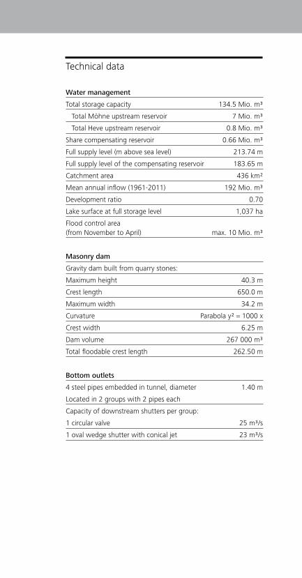
Technical data
Water management
Total storage capacity 134.5 Mio. m³
Total Möhne upstream reservoir 7 Mio. m³
Total Heve upstream reservoir 0.8 Mio. m³
Share compensating reservoir 0.66 Mio. m³
Full supply level (m above sea level) 213.74 m
Full supply level of the compensating reservoir 183.65 m
Catchment area 436 km²
Mean annual inflow (1961-2011) 192 Mio. m³
Development ratio 0.70
Lake surface at full storage level 1,037 ha
Flood control area (from November to April) max. 10 Mio. m³
Masonry dam
Gravity dam built from quarry stones:
Maximum height 40.3 m
Crest length 650.0 m
Maximum width 34.2 m
Curvature Parabola y² = 1000 x
Crest width 6.25 m
Dam volume 267 000 m³
Total floodable crest length 262.50 m
Bottom outlets
4 steel pipes embedded in tunnel, diameter 1.40 m
Located in 2 groups with 2 pipes each
Capacity of downstream shutters per group:
1 circular valve 25 m³/s
1 oval wedge shutter with conical jet 23 m³/s
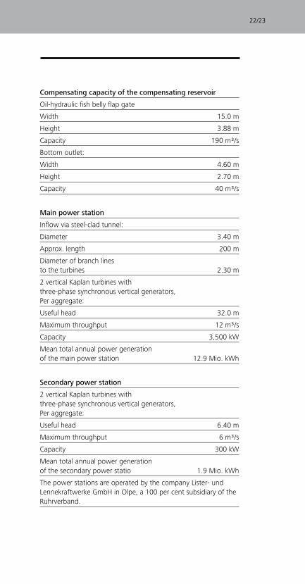
Compensating capacity of the compensating reservoir
Oil-hydraulic fish belly flap gate
Width 15.0 m
Height 3.88 m
Capacity 190 m³/s
Bottom outlet:
Width 4.60 m
Height 2.70 m
Capacity 40 m³/s
Main power station
Inflow via steel-clad tunnel:
Diameter 3.40 m
Approx. length 200 m
Diameter of branch lines to the turbines 2.30 m
2 vertical Kaplan turbines with three-phase synchronous vertical generators, Per aggregate:
Useful head 32.0 m
Maximum throughput 12 m³/s
Capacity 3,500 kW
Mean total annual power generation of the main power station 12.9 Mio. kWh
Secondary power station
2 vertical Kaplan turbines with three-phase synchronous vertical generators, Per aggregate:
Useful head 6.40 m
Maximum throughput 6 m³/s
Capacity 300 kW
Mean total annual power generation of the secondary power statio 1.9 Mio. kWh
The power stations are operated by the company Lister- und Lennekraftwerke GmbH in Olpe, a 100 per cent subsidiary of the Ruhrverband.
22/23
Top Related