


Languages
Pages
Legal


SIMATIC TI505
Thermocouple Input Module
User Manual
Order Number: PPX:505–8111–3Manual Assembly Number: 2586546–0037Third Edition

01/21/92
Copyright 1994 by Siemens Industrial Automation, Inc. All Rights Reserved — Printed in USA
Reproduction, transmission or use of this document orcontents is not permitted without express consent ofSiemens Industrial Automation, Inc. All rights, including rightscreated by patent grant or registration of a utility model ordesign, are reserved.
Since Siemens Industrial Automation, Inc. does not possessfull access to data concerning all of the uses and applicationsof customer’s products, we do not assume responsibility eitherfor customer product design or for any infringements of patentsor rights of others which may result from our assistance.
Technical data is subject to change.
We check the contents of every manual for accuracy at thetime it is approved for printing; however, there may beundetected errors. Any errors found will be corrected insubsequent editions. Any suggestions for improvement arewelcomed.

MANUAL PUBLICATION HISTORY
SIMATIC TI505 Thermocouple Input Module User ManualOrder Manual Number: PPX:505–8111–3Refer to this history in all correspondence and/or discussion about this manual.
Event Date Description
Original Issue 10/90 Original Issue (2586751–0001)Second Edition 12/92 Second Edition (2586751–0002)Third Edition 05/94 Third Edition (2586751–0003)

LIST OF EFFECTIVE PAGES
Pages Description Pages Description
Cover/Copyright ThirdHistory/Effective Pages Thirdiii — vii Third
1-1 — 1-4 Third2-1 — 2-8 Third3-1 — 3-8 Third4-1 — 4-4 ThirdA-1 — A-10 ThirdB-1 — B-2 ThirdIndex-1 — Index-2 Third
Registration Third

Contents iii
Contents
Preface
Chapter 1 Product Overview1.1 General Description 1-2. . . . . . . . . . . . . . . . . . . . . . . . . . . . . . . . . . . . . . . . . . . . . . . . . . . . . . . . . . . .
Overview 1-2. . . . . . . . . . . . . . . . . . . . . . . . . . . . . . . . . . . . . . . . . . . . . . . . . . . . . . . . . . . . . . . . . . . . . . Module Features 1-2. . . . . . . . . . . . . . . . . . . . . . . . . . . . . . . . . . . . . . . . . . . . . . . . . . . . . . . . . . . . . . . .
1.2 Additional Feature Descriptions 1-4. . . . . . . . . . . . . . . . . . . . . . . . . . . . . . . . . . . . . . . . . . . . . . . . Cold Junction Compensation 1-4. . . . . . . . . . . . . . . . . . . . . . . . . . . . . . . . . . . . . . . . . . . . . . . . . . . Data Sampling Rate and Linearization 1-4. . . . . . . . . . . . . . . . . . . . . . . . . . . . . . . . . . . . . . . . . . . Data Word Resolution 1-4. . . . . . . . . . . . . . . . . . . . . . . . . . . . . . . . . . . . . . . . . . . . . . . . . . . . . . . . . . . Power Required 1-4. . . . . . . . . . . . . . . . . . . . . . . . . . . . . . . . . . . . . . . . . . . . . . . . . . . . . . . . . . . . . . . . Probe Temperature Ranges 1-4. . . . . . . . . . . . . . . . . . . . . . . . . . . . . . . . . . . . . . . . . . . . . . . . . . . . .
Chapter 2 Installing the Module2.1 Overview 2-2. . . . . . . . . . . . . . . . . . . . . . . . . . . . . . . . . . . . . . . . . . . . . . . . . . . . . . . . . . . . . . . . . . . . . . .
Installation Tasks 2-2. . . . . . . . . . . . . . . . . . . . . . . . . . . . . . . . . . . . . . . . . . . . . . . . . . . . . . . . . . . . . . . . Handling the Module 2-3. . . . . . . . . . . . . . . . . . . . . . . . . . . . . . . . . . . . . . . . . . . . . . . . . . . . . . . . . . . Inspecting the Module 2-3. . . . . . . . . . . . . . . . . . . . . . . . . . . . . . . . . . . . . . . . . . . . . . . . . . . . . . . . . .
2.2 Setting Options 2-4. . . . . . . . . . . . . . . . . . . . . . . . . . . . . . . . . . . . . . . . . . . . . . . . . . . . . . . . . . . . . . . . . Overview 2-4. . . . . . . . . . . . . . . . . . . . . . . . . . . . . . . . . . . . . . . . . . . . . . . . . . . . . . . . . . . . . . . . . . . . . . Setting Input Type (Dipswitches 1, 2, and 3) 2-5. . . . . . . . . . . . . . . . . . . . . . . . . . . . . . . . . . . . . . . Setting 5F/5C (Dipswitch 4) 2-5. . . . . . . . . . . . . . . . . . . . . . . . . . . . . . . . . . . . . . . . . . . . . . . . . . . . . . Selecting Engineering or Scaling Format (Dipswitch 5) 2-5. . . . . . . . . . . . . . . . . . . . . . . . . . . . Setting 50 or 60 Hz (Dipswitch 6) 2-5. . . . . . . . . . . . . . . . . . . . . . . . . . . . . . . . . . . . . . . . . . . . . . . . . Setting INP or CJ (Dipswitch 7) 2-5. . . . . . . . . . . . . . . . . . . . . . . . . . . . . . . . . . . . . . . . . . . . . . . . . . . Setting RUN or CAL (Dipswitch 8) 2-5. . . . . . . . . . . . . . . . . . . . . . . . . . . . . . . . . . . . . . . . . . . . . . . . . Using the Store Switch 2-5. . . . . . . . . . . . . . . . . . . . . . . . . . . . . . . . . . . . . . . . . . . . . . . . . . . . . . . . . . .
2.3 Connecting the Input Wires 2-6. . . . . . . . . . . . . . . . . . . . . . . . . . . . . . . . . . . . . . . . . . . . . . . . . . . . . . General Wiring Considerations 2-6. . . . . . . . . . . . . . . . . . . . . . . . . . . . . . . . . . . . . . . . . . . . . . . . . . Wiring the Module Input Connector 2-6. . . . . . . . . . . . . . . . . . . . . . . . . . . . . . . . . . . . . . . . . . . . . .
2.4 Inserting the Module Into the Base 2-8. . . . . . . . . . . . . . . . . . . . . . . . . . . . . . . . . . . . . . . . . . . . . . . Installing the Module 2-8. . . . . . . . . . . . . . . . . . . . . . . . . . . . . . . . . . . . . . . . . . . . . . . . . . . . . . . . . . . Tightening Module Screws 2-8. . . . . . . . . . . . . . . . . . . . . . . . . . . . . . . . . . . . . . . . . . . . . . . . . . . . . . . Power Requirements 2-8. . . . . . . . . . . . . . . . . . . . . . . . . . . . . . . . . . . . . . . . . . . . . . . . . . . . . . . . . . . .
iv Contents
Chapter 3 Placing the Module in Operation3.1 Overview 3-2. . . . . . . . . . . . . . . . . . . . . . . . . . . . . . . . . . . . . . . . . . . . . . . . . . . . . . . . . . . . . . . . . . . . . . .
Flow of Tasks 3-2. . . . . . . . . . . . . . . . . . . . . . . . . . . . . . . . . . . . . . . . . . . . . . . . . . . . . . . . . . . . . . . . . . . .
3.2 Programming the Controller 3-3. . . . . . . . . . . . . . . . . . . . . . . . . . . . . . . . . . . . . . . . . . . . . . . . . . . . . Programming Devices 3-3. . . . . . . . . . . . . . . . . . . . . . . . . . . . . . . . . . . . . . . . . . . . . . . . . . . . . . . . . . Updating Module Configuration Data in the PLC 3-3. . . . . . . . . . . . . . . . . . . . . . . . . . . . . . . . .
3.3 Defining the Module’s Input to the Controller 3-4. . . . . . . . . . . . . . . . . . . . . . . . . . . . . . . . . . . . . Data Word Format 3-4. . . . . . . . . . . . . . . . . . . . . . . . . . . . . . . . . . . . . . . . . . . . . . . . . . . . . . . . . . . . . .
3.4 Module Performance Considerations 3-5. . . . . . . . . . . . . . . . . . . . . . . . . . . . . . . . . . . . . . . . . . . . Overview 3-5. . . . . . . . . . . . . . . . . . . . . . . . . . . . . . . . . . . . . . . . . . . . . . . . . . . . . . . . . . . . . . . . . . . . . . Millivolt Performance Data 3-5. . . . . . . . . . . . . . . . . . . . . . . . . . . . . . . . . . . . . . . . . . . . . . . . . . . . . . Thermocouple Performance Data 3-5. . . . . . . . . . . . . . . . . . . . . . . . . . . . . . . . . . . . . . . . . . . . . . . Thermocouple Probe Output Characteristics 3-8. . . . . . . . . . . . . . . . . . . . . . . . . . . . . . . . . . . . .
Chapter 4 Troubleshooting the Module4.1 Using Error Words to Identify Problems 4-2. . . . . . . . . . . . . . . . . . . . . . . . . . . . . . . . . . . . . . . . . . . .
4.2 Identifying Problems Without Error Words 4-4. . . . . . . . . . . . . . . . . . . . . . . . . . . . . . . . . . . . . . . . .
Appendix A Calibrating the ModuleA.1 Preparing to Calibrate the Module A-2. . . . . . . . . . . . . . . . . . . . . . . . . . . . . . . . . . . . . . . . . . . . . . .
Overview A-2. . . . . . . . . . . . . . . . . . . . . . . . . . . . . . . . . . . . . . . . . . . . . . . . . . . . . . . . . . . . . . . . . . . . . . . Flow of Tasks A-2. . . . . . . . . . . . . . . . . . . . . . . . . . . . . . . . . . . . . . . . . . . . . . . . . . . . . . . . . . . . . . . . . . . . Preliminary Steps A-2. . . . . . . . . . . . . . . . . . . . . . . . . . . . . . . . . . . . . . . . . . . . . . . . . . . . . . . . . . . . . . . .
A.2 Calibrating Inputs A-3. . . . . . . . . . . . . . . . . . . . . . . . . . . . . . . . . . . . . . . . . . . . . . . . . . . . . . . . . . . . . . .
A.3 Calibrating Cold Junction A-4. . . . . . . . . . . . . . . . . . . . . . . . . . . . . . . . . . . . . . . . . . . . . . . . . . . . . . . Changes to the CJ Calibration Procedure A-6. . . . . . . . . . . . . . . . . . . . . . . . . . . . . . . . . . . . . . . . Field Connector Errors during Thermocouple Measurement A-7. . . . . . . . . . . . . . . . . . . . . . . Higher Precision Calibration: Method 1 A-7. . . . . . . . . . . . . . . . . . . . . . . . . . . . . . . . . . . . . . . . . . . Example of a Worst Case Error A-8. . . . . . . . . . . . . . . . . . . . . . . . . . . . . . . . . . . . . . . . . . . . . . . . . . . Typical Mean Accuracy A-8. . . . . . . . . . . . . . . . . . . . . . . . . . . . . . . . . . . . . . . . . . . . . . . . . . . . . . . . . Higher Precision Calibration: Method 2 A-8. . . . . . . . . . . . . . . . . . . . . . . . . . . . . . . . . . . . . . . . . . . Example of a Worst Case Error A-9. . . . . . . . . . . . . . . . . . . . . . . . . . . . . . . . . . . . . . . . . . . . . . . . . . . Typical Mean Accuracy A-9. . . . . . . . . . . . . . . . . . . . . . . . . . . . . . . . . . . . . . . . . . . . . . . . . . . . . . . . .
Appendix B Specifications . . . . . . . . . . . . . . . . . . . . . . . . . . . . . . . . . . . . . . . . . . . B-1

Contents v
List of Figures
1-1 Series 505 Thermocouple Input Module 1-3. . . . . . . . . . . . . . . . . . . . . . . . . . . . . . . . . . . . . . . . . .
2-1 Flowchart of Installation 2-2. . . . . . . . . . . . . . . . . . . . . . . . . . . . . . . . . . . . . . . . . . . . . . . . . . . . . . . . . 2-2 Jumper and Dipswitch Locations 2-4. . . . . . . . . . . . . . . . . . . . . . . . . . . . . . . . . . . . . . . . . . . . . . . . 2-3 Setting Module Configuration 2-5. . . . . . . . . . . . . . . . . . . . . . . . . . . . . . . . . . . . . . . . . . . . . . . . . . . 2-4 User Wiring Terminations 2-7. . . . . . . . . . . . . . . . . . . . . . . . . . . . . . . . . . . . . . . . . . . . . . . . . . . . . . . . . 2-5 Inserting the Module Into the Base 2-8. . . . . . . . . . . . . . . . . . . . . . . . . . . . . . . . . . . . . . . . . . . . . . .
3-1 Flowchart of Operation 3-2. . . . . . . . . . . . . . . . . . . . . . . . . . . . . . . . . . . . . . . . . . . . . . . . . . . . . . . . . 3-2 Sample I/O Definition Chart 3-3. . . . . . . . . . . . . . . . . . . . . . . . . . . . . . . . . . . . . . . . . . . . . . . . . . . . . 3-3 Word (WX) Bit Layout 3-4. . . . . . . . . . . . . . . . . . . . . . . . . . . . . . . . . . . . . . . . . . . . . . . . . . . . . . . . . . . .
4-1 RLL Example for Error Detection 4-3. . . . . . . . . . . . . . . . . . . . . . . . . . . . . . . . . . . . . . . . . . . . . . . . . .
A-1 Flowchart of Calibration A-2. . . . . . . . . . . . . . . . . . . . . . . . . . . . . . . . . . . . . . . . . . . . . . . . . . . . . . . . . A-2 User Wiring Terminations A-4. . . . . . . . . . . . . . . . . . . . . . . . . . . . . . . . . . . . . . . . . . . . . . . . . . . . . . . . . A-3 Setting Module Configuration A-5. . . . . . . . . . . . . . . . . . . . . . . . . . . . . . . . . . . . . . . . . . . . . . . . . . .

vi Contents
List of Tables
1-1 Thermocouple Probe Type Temperature Ranges 1-4. . . . . . . . . . . . . . . . . . . . . . . . . . . . . . . . . .
2-1 Probe Type and Extension Wire Descriptions 2-6. . . . . . . . . . . . . . . . . . . . . . . . . . . . . . . . . . . . . .
3-1 Millivolt Operating Characteristics 3-5. . . . . . . . . . . . . . . . . . . . . . . . . . . . . . . . . . . . . . . . . . . . . . . 3-2 Module Performance Using J Probe Measuring 0 to 760°C 3-6. . . . . . . . . . . . . . . . . . . . . . . . 3-3 Module Performance Using J Probe Measuring Near –210°C 3-7. . . . . . . . . . . . . . . . . . . . . . 3-4 Accuracy for All Supported Probe Types Above 0°C 3-7. . . . . . . . . . . . . . . . . . . . . . . . . . . . . . 3-5 T/C Probe Output Characteristics 3-8. . . . . . . . . . . . . . . . . . . . . . . . . . . . . . . . . . . . . . . . . . . . . . . .
4-1 Thermocouple Module Error Words 4-2. . . . . . . . . . . . . . . . . . . . . . . . . . . . . . . . . . . . . . . . . . . . . . . 4-2 Causes and Corrective Action for Faulty Operation 4-4. . . . . . . . . . . . . . . . . . . . . . . . . . . . . . .
A-1 T/C Probe Output Characteristics A-10. . . . . . . . . . . . . . . . . . . . . . . . . . . . . . . . . . . . . . . . . . . . . . . .
B-1 Environmental Specifications B-1. . . . . . . . . . . . . . . . . . . . . . . . . . . . . . . . . . . . . . . . . . . . . . . . . . . . B-2 Electrical/Performance Specifications B-2. . . . . . . . . . . . . . . . . . . . . . . . . . . . . . . . . . . . . . . . . . .

Preface viiThermocouple Input Module User Manual
Preface
This manual is a guide to help you set up, install, configure, calibrate, andtroubleshoot the Series 505 Thermocouple Input Module (PPX:505–7028).Additional information about installing, programming, and troubleshootingSeries 505/Series500 PLCs and their I/O modules is located in thefollowing manuals.
• SIMATIC TI505 Programming Reference Manual, (2586546-0051)
• Installation and hardware manual(s) shipped with your Series 500/505PLC
To order additional manuals, contact your Siemens Industrial Automation,Inc. distributor.
The Thermocouple Input Module complies with the standards of thefollowing agencies:
• Underwriters Laboratories: UL Listed (Industrial Control Equipment)
• Canadian Standards Association: CSA Certified (Process ControlEquipment)
• Factory Mutual Approved; Class I, Div. 2 Hazardous Locations
• Verband Deutscher Elektrotechniker (VDE) 0160 Clearance/Creepagefor Electrical Equipment (Self-Compliance)
This product has been developed with consideration of the draft standard ofthe International Electrotechnical Commission Committee proposedstandard (IEC-65A/WG6) for programmable controllers. Contact yourSiemens Industrial Automation, Inc. distributor for a listing of thestandards to which Series 505 complies.
If you need information that is not included in this manual, or if you haveproblems using the module, contact your your Siemens IndustrialAutomation, Inc. distributor or sales agent. If you need assistance incontacting your distributor or sales agent, call 1–800–964-4114 in theUnited States.
Agency Approvals
Need Assistance?

Product Overview 1-1Thermocouple Input Module User Manual
Chapter 1
Product Overview
1.1 General Description 1-2. . . . . . . . . . . . . . . . . . . . . . . . . . . . . . . . . . . . . . . . . . . . . . . . . . . . . . . . . . . . Overview 1-2. . . . . . . . . . . . . . . . . . . . . . . . . . . . . . . . . . . . . . . . . . . . . . . . . . . . . . . . . . . . . . . . . . . . . . . Module Features 1-2. . . . . . . . . . . . . . . . . . . . . . . . . . . . . . . . . . . . . . . . . . . . . . . . . . . . . . . . . . . . . . . .
1.2 Additional Feature Descriptions 1-4. . . . . . . . . . . . . . . . . . . . . . . . . . . . . . . . . . . . . . . . . . . . . . . . Cold Junction Compensation 1-4. . . . . . . . . . . . . . . . . . . . . . . . . . . . . . . . . . . . . . . . . . . . . . . . . . . Data Sampling Rate and Linearization 1-4. . . . . . . . . . . . . . . . . . . . . . . . . . . . . . . . . . . . . . . . . . . Data Word Resolution 1-4. . . . . . . . . . . . . . . . . . . . . . . . . . . . . . . . . . . . . . . . . . . . . . . . . . . . . . . . . . . Power Required 1-4. . . . . . . . . . . . . . . . . . . . . . . . . . . . . . . . . . . . . . . . . . . . . . . . . . . . . . . . . . . . . . . . Probe Temperature Ranges 1-4. . . . . . . . . . . . . . . . . . . . . . . . . . . . . . . . . . . . . . . . . . . . . . . . . . . . .

Product Overview1-2 Thermocouple Input Module User Manual
1.1 General Description
The TI505 Thermocouple Input Module is a single-wide module that can beused with all Series 505 and Series 500 PLCs. This module mounts in aTI505 base. Series 500 PLCs can communicate with it through TI505 DBCsor RBCs.
The module has the following features:
• Eight differential inputs
• +50 mV input voltage range
• ANSI-defined thermocouple types J, K, T, E, R, S, N and mV can beused as input sources; one selection for all eight inputs
• 250-ms update time for one or all channels
• 14-bit full-scale data resolution
• Isolation: 1500 Vrms between input points, 1500 Vrms between theinput section and the PLC
• Thermocouples can be any combination of grounded and ungrounded
• Open thermocouple probe detection
• Automatic cold junction compensation
• Engineering units (°F or °C) or scaled integer data formats
• Calibration requires precision mV source only
• All eight input points are calibrated simultaneously
• Cold junction can be calibrated independently
• Module uses solid state non-volatile memory for calibration parameters(no trim-pots)
• Removable user wiring connector
• Built-in diagnostics reports through error words
Additional specifications are listed in Appendix B.
Overview
Module Features

Product Overview 1-3Thermocouple Input Module User Manual
A000516
Figure 1-1 Series 505 Thermocouple Input Module

Product Overview1-4 Thermocouple Input Module User Manual
1.2 Additional Feature Descriptions
The module provides automatic cold junction (CJ) compensation forthermocouple input points. The connector temperature is measured by asensor at the input connector. This value is then used to compensate for thesmall junction voltages that occur at the connector terminals.
Inputs are sampled every 250 ms @ 60 Hz or 240 ms @ 50 Hz, providingdigital line filtering. Input circuits also include a three-section, low-passfilter to provide a high level of noise rejection. NTIS (formerly NBS)standard equations are used for thermocouple readings to ensure accuratelinearization in reported data. Linearization for type N probe assumes#28-gauge probe wire below 0C, and #14-gauge probe wire above 0C.
The module provides at least 14-bit, full-scale resolution. With engineeringunits selected, the ±50 mV signal range is reported as a signed integer(±10,000). The module also provides improved resolution for temperaturedata by using a ×10 multiplier for F and C readings. The actual resolutionof temperature data in degrees depends on the probe type, and themeasurement temperatures within the probe range. Typical temperatureresolution is 0.1C.
You can also select scaled integer data format. Details on scaled integerappear in Section 3.3.
Module power requirements (drawn from the base) are the following.
• +5 volt supply —typically 1.6 W; does not exceed 2.2 W
• –5 volt supply — less than 0.01 W
Table 1-1 shows the temperature ranges of the seven probe types supportedby this module.
Table 1-1 Thermocouple Probe Type Temperature Ranges
Probe Type Temperature RangeC F
J –210 to 760 –346 to 1400
K –220 to 1320 –364 to 2408
T –230 to 400 –382 to 752
E –240 to 700 –400 to 1292
R 0 to 1768 32 to 3214
S 0 to 1768 32 to 3214
N –200 to 1300 –328 to 2372
Cold JunctionCompensation
Data SamplingRate andLinearization
Data WordResolution
Power Required
Probe TemperatureRanges

Installing the Module 2-1Thermocouple Input Module User Manual
Chapter 2
Installing the Module
2.1 Overview 2-2. . . . . . . . . . . . . . . . . . . . . . . . . . . . . . . . . . . . . . . . . . . . . . . . . . . . . . . . . . . . . . . . . . . . . . . Installation Tasks 2-2. . . . . . . . . . . . . . . . . . . . . . . . . . . . . . . . . . . . . . . . . . . . . . . . . . . . . . . . . . . . . . . . Handling the Module 2-3. . . . . . . . . . . . . . . . . . . . . . . . . . . . . . . . . . . . . . . . . . . . . . . . . . . . . . . . . . . Inspecting the Module 2-3. . . . . . . . . . . . . . . . . . . . . . . . . . . . . . . . . . . . . . . . . . . . . . . . . . . . . . . . . .
2.2 Setting Options 2-4. . . . . . . . . . . . . . . . . . . . . . . . . . . . . . . . . . . . . . . . . . . . . . . . . . . . . . . . . . . . . . . . . Overview 2-4. . . . . . . . . . . . . . . . . . . . . . . . . . . . . . . . . . . . . . . . . . . . . . . . . . . . . . . . . . . . . . . . . . . . . . . Setting Input Type (Dipswitches 1, 2, and 3) 2-5. . . . . . . . . . . . . . . . . . . . . . . . . . . . . . . . . . . . . . . Setting F/C (Dipswitch 4) 2-5. . . . . . . . . . . . . . . . . . . . . . . . . . . . . . . . . . . . . . . . . . . . . . . . . . . . . . Selecting Engineering or Scaling Format (Dipswitch 5) 2-5. . . . . . . . . . . . . . . . . . . . . . . . . . . . Setting 50 or 60 Hz (Dipswitch 6) 2-5. . . . . . . . . . . . . . . . . . . . . . . . . . . . . . . . . . . . . . . . . . . . . . . . . Setting INP or CJ (Dipswitch 7) 2-5. . . . . . . . . . . . . . . . . . . . . . . . . . . . . . . . . . . . . . . . . . . . . . . . . . . Setting RUN or CAL (Dipswitch 8) 2-5. . . . . . . . . . . . . . . . . . . . . . . . . . . . . . . . . . . . . . . . . . . . . . . . . Using the Store Switch 2-5. . . . . . . . . . . . . . . . . . . . . . . . . . . . . . . . . . . . . . . . . . . . . . . . . . . . . . . . . . .
2.3 Connecting the Input Wires 2-6. . . . . . . . . . . . . . . . . . . . . . . . . . . . . . . . . . . . . . . . . . . . . . . . . . . . . . General Wiring Considerations 2-6. . . . . . . . . . . . . . . . . . . . . . . . . . . . . . . . . . . . . . . . . . . . . . . . . . Wiring the Module Input Connector 2-6. . . . . . . . . . . . . . . . . . . . . . . . . . . . . . . . . . . . . . . . . . . . . .
2.4 Inserting the Module Into the Base 2-8. . . . . . . . . . . . . . . . . . . . . . . . . . . . . . . . . . . . . . . . . . . . . . . Installing the Module 2-8. . . . . . . . . . . . . . . . . . . . . . . . . . . . . . . . . . . . . . . . . . . . . . . . . . . . . . . . . . . Tightening Module Screws 2-8. . . . . . . . . . . . . . . . . . . . . . . . . . . . . . . . . . . . . . . . . . . . . . . . . . . . . . . Power Requirements 2-8. . . . . . . . . . . . . . . . . . . . . . . . . . . . . . . . . . . . . . . . . . . . . . . . . . . . . . . . . . . .

Installing the Module2-2 Thermocouple Input Module User Manual
2.1 Overview
Figure 2-1 shows the general order in which you install the module.
Insert the module into the base
Set the module configuration switches
Plug the input connector into the module
Apply power to the system
Wire the input device wires to the input connector
Visually inspect the module
I000334
Figure 2-1 Flowchart of Installation
Installation Tasks

Installing the Module 2-3Thermocouple Input Module User Manual
Many integrated circuit (IC) devices are susceptible to damage by thedischarge of static electricity. Follow the suggestions listed below to reducethe probability of damage to these devices when you are handling acontroller, a base controller, or any of the I/O modules.
Both the module and the person handling the module should be at the sameground potential. Also, follow these guidelines.
• Transport the module in an anti-static container, or use antistaticmaterial.
• Ensure that the work area has a conductive pad with a lead connectingit to a common ground.
• Ground yourself by making contact with the conductive pad and/or bywearing a grounded wrist strap.
Inspect the module for any visible damage before setting any selectablefeatures. If damage is detected, contact your Siemens IndustrialAutomation, Inc. distributor or sales agent for further instructions. If youneed assistance in contacting your distributor or sales agent in the UnitedStates, call 1–800–964-4114.
Handling theModule
Inspecting theModule
Installing the Module2-4 Thermocouple Input Module User Manual
2.2 Setting Options
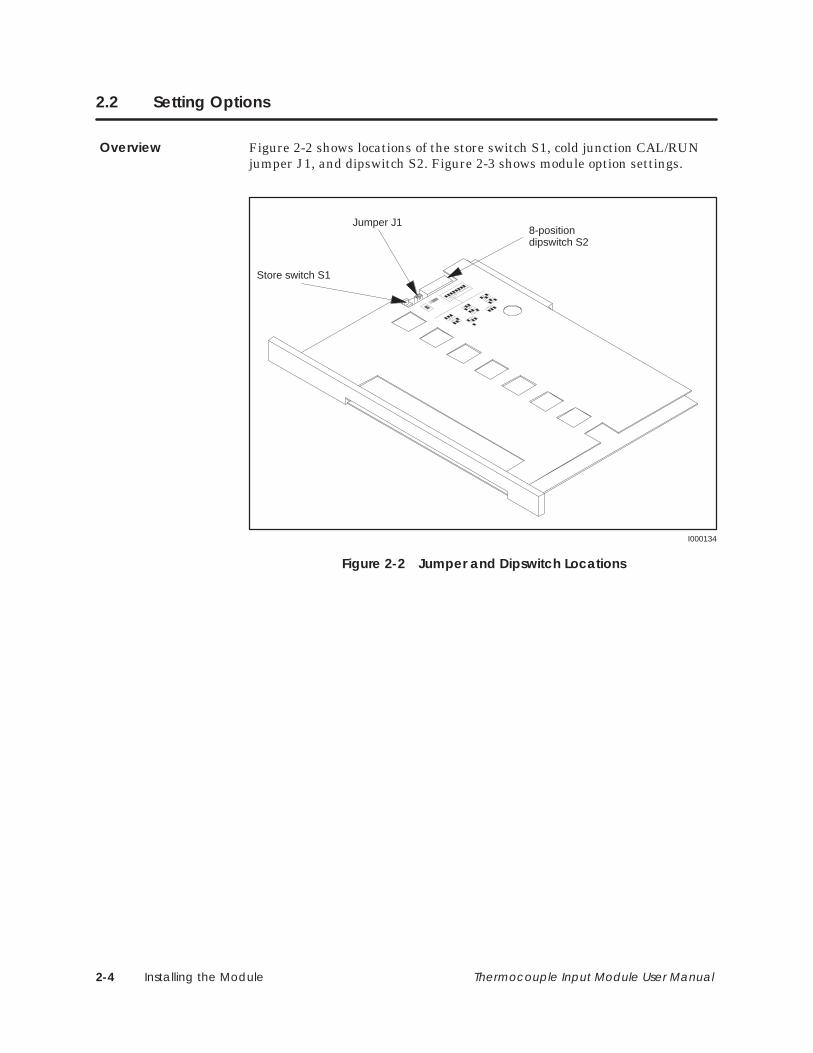
Figure 2-2 shows locations of the store switch S1, cold junction CAL/RUNjumper J1, and dipswitch S2. Figure 2-3 shows module option settings.
8-positiondipswitch S2
Store switch S1
Jumper J1
I000134
Figure 2-2 Jumper and Dipswitch Locations
Overview

Installing the Module 2-5Thermocouple Input Module User Manual
Figure 2-3 illustrates the configuration label on the module cover; themodule is shipped with dipswitches and the cold junction jumper set inthese default positions. As shown, the first three dipswitches are used to setthe input type.
I000138
J K T
E R S
N mV = Depressed
ST
OR
E CA
L
RU
N
F ° EN
G60
Hz
INP
RU
N
SC
ALE
50H
zC
JC
ALC °
INPUT TYPE
1 2 3 4 5 6 7 8
COLDJUNCTION
Figure 2-3 Setting Module Configuration
Set the F/C (degrees Fahrenheit/Centigrade) switch to match the dataformat you want reported to the PLC when using engineering units.
When ENG (engineering) is selected, the module provides formatteddata: ±50 mV as ±10000; thermocouple reading as (C × 10) or (F × 10).When SCALE (scaled integer) is selected, the module provides formatteddata: ±50 mV as ±32000; thermocouple range as 0 to 32000.
For maximum noise rejection, set the 50 Hz/60 Hz switch to match the linefrequency that is being used to power the system.
NOTE: The next three switches are provided for calibrating the module. Themodule has been calibrated at the factory and may be put into service afterverifying that dipswitch 8 is in the RUN position.
The INP/CJ dipswitch is used to select whether the inputs or the CJreference is to be calibrated. This dipswitch is only enabled when theRUN/CAL dipswitch is set to CAL.
The RUN/CAL dipswitch is used to select the CAL mode when calibration isrequired.
After completing a module calibration step, the STORE switch is used tostore the changes in non-volatile memory.
Setting Input Type(Dipswitches 1, 2,and 3)
Setting F/C(Dipswitch 4)
SelectingEngineering orScaling Format(Dipswitch 5)
Setting 50 or 60 Hz(Dipswitch 6)
Setting INP or CJ(Dipswitch 7)
Setting RUN or CAL(Dipswitch 8)
Using the StoreSwitch

Installing the Module2-6 Thermocouple Input Module User Manual
2.3 Connecting the Input Wires
To minimize errors and the potential effects of external noise, follow theseguidelines when connecting the module input wires.
• Extension wire, if used, and the connecting probe must be the sametype of thermocouple wire.
• Use the shortest possible input wires (recommended maximum of 1,000feet of extension wire). The measurement error is 6 µV or 0.006% offull-scale range (FSR) per 1,000 Ω of input lead resistance (500 Ω perlead).
• Avoid placing signal wires parallel to high-energy wires. If the twomust meet, cross them at right angles.
• Avoid bending the wire into sharp angles.
• Use wireways for wire routing.
• When using shielded wires, ground the shield only at the source end forbetter noise immunity. If shielding at the source end is impractical,ground the shield to the chassis terminals of the module inputconnector, and run a wire from the chassis terminals to the earthground on the base, as shown in Figure 2-5.
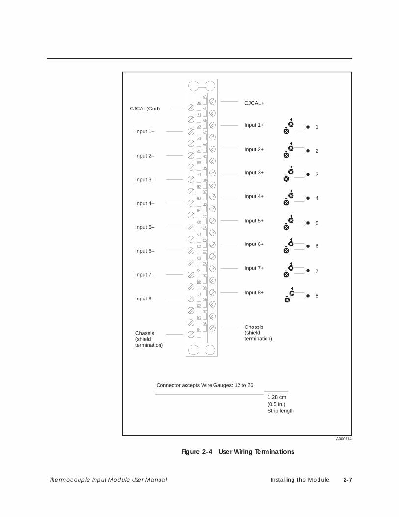
Refer to Figure 2-4 when attaching wires to the module input connector.Normally, it is easier to first attach input wires to the connector, then plugthe connector into the module. Also, follow these guidelines:
• Ensure that you observe thermocouple probe wire polarity; Table 2-1shows lead compositions, colors, and polarities for the seven supportedthermocouple probe types.
• Label the input wires, and record this information (along with moduledipswitch configuration) in an appropriate location.
Table 2-1 Probe Type and Extension Wire Descriptions
Probe Type Negative (–) Lead Positive (+) Lead
J Copper-Nickel (Red) Iron (White)
K Nickel-Aluminum (Red) Nickel-Chromium (Yellow)
T Copper-Nickel (Red) Copper (Blue)
E Copper-Nickel (Red) Nickel-Chromium (Purple)
R Platinum (Red) Platinum-13 % Rhodium (Black)
S Platinum (Red) Platinum-10 % Rhodium (Black)
N Nisil (Red) Nicrosil (Orange)
General WiringConsiderations
Wiring the ModuleInput Connector
Installing the Module 2-7Thermocouple Input Module User Manual
Input 1–
Input 2–
Input 3–
Input 4–
Input 5–
Input 6–
Input 7–
Input 8–
Input 1+
Input 2+
Input 3+
Input 4+
Input 5+
Input 6+
Input 7+
Input 8+
1.28 cm(0.5 in.)
Connector accepts Wire Gauges: 12 to 26
CJCAL+CJCAL(Gnd)
7
6
5
4
3
2
1
Chassis(shieldtermination)
Chassis(shieldtermination)
Strip length
8
A000514
Figure 2-4 User Wiring Terminations

Installing the Module2-8 Thermocouple Input Module User Manual
2.4 Inserting the Module Into the Base
To minimize potential shock, turn off power to the I/O base and anymodules installed in the base, before inserting or removing amodule. Failure to do so may result in potential injury to personnelor damage to equipment.
Install the module in a TI505 base. The thermocouple module performsbetter when placed away from high-energy switching sources. If possible,try to avoid installing the module adjacent to high-energy switchingmodules or other potential sources of EMI (electromagnetic interference).Also, avoid placing the module beside any device that produces excessiveheat. Excessive heat can change the ambient temperature of thethermocouple CJ sensor, thereby distorting CJ measurement values.
Back PlaneConnectors
I000135
0.3 N–m (2.61 in.-lbs.) min torque
0.6 N–m (5.22 in.-lbs.) max torque
PLCP
S
EarthGround
Figure 2-5 Inserting the Module Into the Base
When tightening the module screws, use the specified torque to achieve agood ground connection between the module bezel and the base.
This module receives its power through the TI505 chassis backplane fromthe chassis power supply. The module requires a maximum of 2.2 W (1.6 Wtypical) of +5 V and 0.01 W of –5 V system power. Compute your powerbudget by adding these values to the requirements of all other modules inthe I/O chassis to prevent overloading the base power supply.
WARNING!
Installing the Module
Tightening ModuleScrews
PowerRequirements

Placing the Module in Operation 3-1Thermocouple Input Module User Manual
Chapter 3
Placing the Module in Operation
3.1 Overview 3-2. . . . . . . . . . . . . . . . . . . . . . . . . . . . . . . . . . . . . . . . . . . . . . . . . . . . . . . . . . . . . . . . . . . . . . . Flow of Tasks 3-2. . . . . . . . . . . . . . . . . . . . . . . . . . . . . . . . . . . . . . . . . . . . . . . . . . . . . . . . . . . . . . . . . . . .
3.2 Programming the Controller 3-3. . . . . . . . . . . . . . . . . . . . . . . . . . . . . . . . . . . . . . . . . . . . . . . . . . . . . Programming Devices 3-3. . . . . . . . . . . . . . . . . . . . . . . . . . . . . . . . . . . . . . . . . . . . . . . . . . . . . . . . . . Updating Module Configuration Data in the PLC 3-3. . . . . . . . . . . . . . . . . . . . . . . . . . . . . . . . .
3.3 Defining the Module’s Input to the Controller 3-4. . . . . . . . . . . . . . . . . . . . . . . . . . . . . . . . . . . . . Data Word Format 3-4. . . . . . . . . . . . . . . . . . . . . . . . . . . . . . . . . . . . . . . . . . . . . . . . . . . . . . . . . . . . . .
3.4 Module Performance Considerations 3-5. . . . . . . . . . . . . . . . . . . . . . . . . . . . . . . . . . . . . . . . . . . . Overview 3-5. . . . . . . . . . . . . . . . . . . . . . . . . . . . . . . . . . . . . . . . . . . . . . . . . . . . . . . . . . . . . . . . . . . . . . . Millivolt Performance Data 3-5. . . . . . . . . . . . . . . . . . . . . . . . . . . . . . . . . . . . . . . . . . . . . . . . . . . . . . Thermocouple Performance Data 3-5. . . . . . . . . . . . . . . . . . . . . . . . . . . . . . . . . . . . . . . . . . . . . . . Thermocouple Probe Output Characteristics 3-8. . . . . . . . . . . . . . . . . . . . . . . . . . . . . . . . . . . . .

Placing the Module in Operation3-2 Thermocouple Input Module User Manual
3.1 Overview
Figure 3-1 shows the general order in which you integrate the thermocouplemodule into your control system. Procedures needed to complete the firsttwo tasks are covered in Chapter 2.
Use TISOFT to program PLC to accept input from the module
Place the module in operation
Ensure that module selectable switches are set correctly
Ensure that module external input wires are attached correctly
I000335
Figure 3-1 Flowchart of Operation
Flow of Tasks

Placing the Module in Operation 3-3Thermocouple Input Module User Manual
3.2 Programming the Controller
You can use TISOFT with an IBM PC/XT or PC/AT -compatiblecomputer or other programming device to add Thermocouple Moduleconfiguration data into your PLC program. Refer to the SIMATIC TI505Programming Reference Manual for specific details on designing a program.
Fill in configuration screens as required. Figure 3-2 is a sample I/O moduledefinition chart. Refer to your TISOFT manual for more detailedinstructions including how to display the Configuration Charts, read yourbase(s), and write the data to the PLC.
I/O MODULE DEFINITION FOR : CHANNEL 1 BASE 00
Slot Address X Y WX WY FunctionI/O Number of Bit and Word I/O Special
123456
78
.....
.....
.....
.....
.....
.....
.....
.....
000100000000000000000000
00000000
.....
.....
.....
.....
.....
.....
.....
.....
000000000000
0000
..
..
..
..
..
..
..
..
000000000000
0000
..
..
..
..
..
..
..
..
0000000000
0000
..
..
..
..
..
..
..
..
0000000000
0000
.......
.......
.......
.......
.......
.......
.......
.......
NoNoNoNoNoNo
NoNo
08 00
Base NumberDisplays number of the current base.
Slot Number Install the module intoany available I/O sloton the Series 505base. See Section 2.4.
I/O AddressThe module is logged in aseight input words (WX).
SF ModuleThermocouple is not anSF Module. The defaultfor this definition is No.
I000713
Figure 3-2 Sample I/O Definition Chart
ProgrammingDevices
Updating ModuleConfiguration Datain the PLC

Placing the Module in Operation3-4 Thermocouple Input Module User Manual
3.3 Defining the Module’s Input to the Controller
Figure 3-3 shows the format for a Thermocouple Module WX point (PLCinput) word. Point measurements are reported as signed integers. The mostsignificant bit (MSB) is used as a sign bit (1 denotes the sign is –). Sixteennumbers, 32752 through 32767, are used to report module errors.
Two types of data formatting are provided: engineering units (ENG) andscaled integer (SCALE).
• When ENG and mV are selected, ±50 mV is represented as ±10000.With ENG and a probe type selected, thermocouple values are presentedas C×10 or F×10, depending on whether you select C or F.
• With SCALE and mV selected, ±50 mV is represented as ±32000. WithSCALE and a probe type selected, the thermocouple range is scaled 0 to32000. This feature is useful in conjunction with PID loop applications.
0
0
1 2
0
3
0
4 5 6 7 8
0
9
0
10 11 12
0
13
0
14
0
15
MSB LSB
Bit
15 Bits for Process ValueSign Bit
I000139
1 1 1 1 0101
(Value = –10000 representing –50 mV with ENG and mV format)
Figure 3-3 Word (WX) Bit Layout
Data Word Format

Placing the Module in Operation 3-5Thermocouple Input Module User Manual
3.4 Module Performance Considerations
The following sections explain performance characteristics when the moduleis set to operate in various operating modes. Consider this informationcarefully when evaluating module performance in your application.
Table 3-1 shows module performance data when operating in the mVconfiguration. Typical performance is achieved when the module isre-calibrated in the user base; this allows the module to comprehend theprecise conditions of the installation. Specification limits apply when themodule is put into service as received from the factory.
Table 3-1 Millivolt Operating Characteristics
Characteristic Typical Specification Limit
Resolution 5 µV or 0.005% 6 µV or 0.006%
Repeatability ±10 µV or ±0.01% ±20 µV or ±0.02%
Mean accuracy ±30 µV or ±0.03% ±60 µV or ±0.06%
Temp coefficient ±10 µV/C or ±0.01%/C ±16 µV/C or ±0.016%/C
Over-/underrange ±55 mV Same as typical
NOTE: Percentages refer to full-scale range (FSR) of 100 mV.
With ENG selected, a full scale input of ±50 mV is presented to the PLC assigned integer ±10000. This means the module provides a resolution of 5 µVper count (1 in 20000) for the full-scale range of 100 mV. Overrange occursat about +55 mV; underrange occurs at about –55 mV.
With SCALE selected, a full scale input of ±50 mV is presented to the PLCas signed integer ±32000:
Scaled integer mV x640.
Overrange occurs above +32751 (about 51.173 mV) and underrange occursbelow –32768 (about –51.200 mV).
The module uses special circuits to determine the temperature of the userwiring connector when it is configured for thermocouple operation. Theconnector terminals often are referred to as the CJ, and the module makescorrections for error voltages that occur at this junction. These specialcircuits can contribute an additional maximum error of ±0.5C.
NOTE: The module connector temperature can be monitored by installing ajumper wire (short) between input terminals of an unused channel.
Overview
MillivoltPerformance Data
ThermocouplePerformance Data

Placing the Module in Operation3-6 Thermocouple Input Module User Manual
Module Performance Considerations (continued)
Other sources that can contribute errors include:
• Standard wire errors for the thermocouple probe type and wire size used
• Mechanical stress on the thermocouple wire in the installation
• Lead wire resistance as described in Section 2.3
• Temperature gradient within the user wiring connector (Appendix A)
• Uneven heating of module and connector (Appendix A)
• Calibrating the module using non-precision voltage sources
NOTE: Table 3-1 through Table 3-4 describe the module performance and donot include errors from the external variables described above.
Table 3-2 shows performance with a J-type probe used between 0C and760C (minimum probe output of 50 µV per C). This table shows Cequivalents for resolution, repeatability, accuracy, and temperaturecoefficient (0.5C in accuracy specification is first converted to µV at theambient temperature and then the µV total is evaluated at the measuredtemperature).
Table 3-2 Module Performance Using J Probe Measuring 0 to 760°C
Characteristic Typical Specification Limit
Resolution 5 µV or 0.1C 6 µV or 0.12C
Repeatability ±10 µV or ±0.2C ±20 µV or ±0.4C
Mean accuracy ± (30 µV + 0.5C) or ±1.1C ± (60 µV + 0.5C) or ±1.7C
Temp coefficient ±10 µV/C or ±0.2C/C ±16 µV/C or ±0.32C/C
Over-/underrange 10C beyond range limit Same as typical
With ENG selected, data to the PLC are C×10 or F×10. Overrange occursat about 10C above maximum temperature and underrange occurs at about10C below minimum temperature in range.
With SCALE selected, data are scaled 0 to 32000, with 0 representing theminimum temperature in range and 32000 representing the maximumtemperature in range. Intermediate temperatures have scaled integervalues determined by the relationship:

Placing the Module in Operation 3-7Thermocouple Input Module User Manual
Scaled Integer(Temp min temp)
(Max temp min temp) 32000

Placing the Module in Operation3-8 Thermocouple Input Module User Manual
For example, overrange for probe type J gives:
Scaled integer overrange(770 C ( 210 C))(760 C ( 210 C))
32000 32330°°
°°
Both typical and worst case performances for any supported probe type canbe determined by using Table 3-5 and Table 3-2. For example: to findmodule performance for Probe Type J measuring near –210C, use Table 3-5and find that the rate-of-change for J probe at –210C is about 20 µV/C.With ambient temperature of 25C, 0.5C is 26 µV. Results appear inTable 3-3.
Table 3-3 Module Performance Using J Probe Measuring Near –210°C
Characteristic Typical Specification Limit
Resolution 5 µV or 0.25°C 6 µV or 0.3°C
Repeatability ±10 µV or ±0.5°C ±20 µV; ±1.0°C
Mean accuracy ±(30 µV + 0.5°C) or ±2.8°C ±(60 µV + 0.5°C); ±4.3°C
Temp coefficient ±10 µV/C or ±0.5C/C ±16 µV/C; ±0.8C/C
Table 3-4 defines the overall performance of the module when it isconfigured for thermocouple operation. This table is derived from theaccuracy parameters of Table 3-2 and probe characteristics identified inTable 3-5.
Table 3-4 Accuracy for All Supported Probe Types Above 0°C
ProbeType
Typical MeanAccuracy
TypicalTemperatureCoefficient
Limits forMean Accuracy
Limits forTemperatureCoefficient
J ±1.1°C ±0.20°C/C ±1.7°C ±0.32°C/C
K ±1.4°C ±0.29°C/C ±2.3°C ±0.46°/C
T ±1.3°C ±0.26°/C ±2.0°C ±0.41°CC
E ±1.0°C ±0.17°C/C ±1.5°C ±0.27°C/C
**R ±2.8°C ±0.83°C/C ±5.3°C ±1.33°C/C
**S ±3.0°C ±0.91°C/C ±5.7°C ±1.45°C/C
N ±1.7°C ±0.38°C/C ±2.8°C ±0.62°C/C
**above 800°C for R & S

Placing the Module in Operation 3-9Thermocouple Input Module User Manual
Module Performance Considerations (continued)
Thermocouple probes are not ideal devices, and overall system accuracydepends upon the probe type being used and the measuring point within theprobe range. Table 3-5 shows typical probe output characteristics.
Table 3-5 T/C Probe Output Characteristics
Probe Type Temperature (°C) Rate-of-change (µV/°C)
J Max 760 °C 64 µV / °C275 °C 55 µV / °C25 °C 52 µV / °C0 °C 50 µV / °C
Min –210 °C 20 µV / °C
K Max 1320 °C 35 µV / °C550 °C 43 µV / °C25 °C 40 µV / °C
0 °C 39 µV / °CMin –220 °C 12 µV / °C
T Max 400 °C 62 µV / °C85 °C 46 µV / °C25 °C 41 µV / °C
0 °C 39 µV / °CMin –230 °C 11 µV / °C
E Max 700 °C 80 µV / °C230 °C 75 µV / °C25 °C 61 µV / °C
0 °C 59 µV / °CMin –240 °C 13 µV / °C
R Max 1768 °C 12 µV / °C884 °C 12 µV / °C25 °C 6 µV / °C
Min 0 °C 5 µV / °C
S Max 1768 °C 11 µV / °C884 °C 11 µV / °C25 °C 6 µV / °C
Min 0 °C 5 µV / °C
N Max 1300 °C 36 µV / °C550 °C 39 µV / °C25 °C 27 µV / °C
0 °C 26 µV / °CMin –200 °C 10 µV / °C
ThermocoupleProbe OutputCharacteristics

Troubleshooting the Module 4-1Thermocouple Input Module User Manual
Chapter 4
Troubleshooting the Module
4.1 Using Error Words to Identify Problems 4-2. . . . . . . . . . . . . . . . . . . . . . . . . . . . . . . . . . . . . . . . . . . .
4.2 Identifying Problems Without Error Words 4-4. . . . . . . . . . . . . . . . . . . . . . . . . . . . . . . . . . . . . . . . .

Troubleshooting the Module4-2 Thermocouple Input Module User Manual
4.1 Using Error Words to Identify Problems
The Thermocouple Input Module contains software routines that can detecthardware and software errors in the module and alert the PLC to the fault.During normal operation, each module data word (corresponding to an inputpoint) reports an individual sensor reading to the PLC. Valid data wordranges depend on the specific thermocouple probe or mV input being used.When a single input fault is detected, a unique error word between 32752and 32767 replaces the point data word. The error word value continues tobe reported until the fault is cleared.
Table 4-1 contains a list of error words that are reported to the PLC. Theseerror words may be used as a guide in troubleshooting your mV- ortemperature-sensing system to determine whether the problem is in themodule, in the external wiring and sensor, or in the programming of themodule. If the fault is in the module, contact your Siemens IndustrialAutomation, Inc. distributor for further information and assistance.
Table 4-1 Thermocouple Module Error Words
SignedInteger Hex Problem Comment/Corrective Action
32767 7FFF Failed module Failure is reported to PLC; MODULE GOOD indicator is off.Repair or replace module as required.
32766 7FFE Channel underrange Input signal level is below normal input range. Check processto determine if it is actually low or, if the thermocouple or mVtransmitter is faulty. Module could be out of calibration.
32765 7FFD Channel overrange Input signal level is above normal input range. Check processto determine if it is actually high or, if the thermocouple ormV transmitter is faulty (if you are using thermocouples, themost likely cause is an open probe). Module could also be outof calibration.
32764 7FFC EEROM storage error Re-calibration required; if error persists, repair or replace themodule.
32763 7FFB Faulty inputcalibration
Calibration procedure was completed but this channel wouldnot accept all data points; re-calibration is required. If errorpersists, repair or replace module.
32762 7FFA CJ out-of-range Check calibration jumper position; re-calibrate the CJ. Ifproblem still persists, repair or replace the module.
32761 7FF9 Incomplete inputcalibration
Requires power cycle or re-calibration to clear. Old values arerestored after power cycle if the module is not re-calibrated.
32760 7FF8 CJ calibrationincomplete
Requires power cycle or re-calibration to clear. Old values arerestored after power cycle if the module is not re-calibrated.
32759 7FF732758 7FF6
32757 7FF532756 7FF4 To be defined as required.
32755 7FF332754 7FF2
32753 7FF132752 7FF0 Calibration mode CAL/RUN switch is set to the CAL position; change to RUN.

Troubleshooting the Module 4-3Thermocouple Input Module User Manual
By incorporating an error-detection routine in your relay ladder logic (RLL)program, you can provide alarms to signal faults detected by the module.Figure 4-1 contains a general example of an error-detection routine, asdescribed in the following statements.
• The first rung loads number 32751 into address location V1, and it loadsnumber 32765 into address location V2.
• The second rung compares WX1 (representing one point on thethermocouple input module) with 32751; if WX1 is greater, C3 turns on.
• The third rung compares WX1 (representing one point on thethermocouple input module) with 32765; if WX1 is equal, C5 turns on.
A: WX1B: V1LT: =GT: C3
C2
LDC 0A: V1N: 32751
Other program steps
C1 is latched on.
Set up error compare value in V1:set up open probe compare in V2.C2 is a dummy (not used) output.
Compare data word for this channelwith 32751. If data word > 32751, C3comes on. LT and C4 are not used. C3 on ⇒ error. C3 off ⇒ no error. C4 is a dummy output.
Compare data word for this channelwith 32765. If data word = 32765, C5turns on. Note that LT and GT are notused. C5 on ⇒ open probe. C5 off ⇒ noopen probe
Other program steps
Required at end of each main program.
C4
CMP 0
I000140
LDC 1A: V2N: 32765
C5
CMP 1
A: WX1B: V2LT: =GT: =
END
NOTE: This sample program checks a single channel only.
C1 C1
C1
C1
C1
C1
Figure 4-1 RLL Example for Error Detection

Troubleshooting the Module4-4 Thermocouple Input Module User Manual
4.2 Identifying Problems Without Error Words
Some problems with wiring, software, or programming do not report errorwords to the PLC. If you suspect a problem, but no error word is reported,check to see if one of the following conditions exists.
• The MODULE GOOD indicator is off.
• A module word value (read by the PLC) is not an expected value.
Table 4-2 Causes and Corrective Action for Faulty Operation
Symptom Probable Cause Corrective Action
Base or PLC is off Turn base or PLC on.
MODULE GOOD
Software failure Power cycle the module to attemptto clear the failure.MODULE GOOD
indicator is off Module not fully seatedin base
Re-install module in the base.
Defective module Replace module.
Wrong connections Trace wiring to ensure it is wiredcorrectly.
Noise on signal wire Use shielded wire — check wirerouting.
Incorrect
Not logged in properly forthe program
Perform AUX 43, or read the I/Oconfiguration.
Incorrectreadings Thermocouple or wiring
failureCheck the thermocouple, extensionwire, and the connectors.
Module out of calibration Re-calibrate the module.
Error word Refer to Table 4-1 for problem andsuggested corrective action.
Module configured wrong Check dipswitch settings.
NOTE: If you cannot resolve your problem, contact your Siemens IndustrialAutomation, Inc. distributor in the U. S. for further assistance.

Calibrating the Module A-1Thermocouple Input Module User Manual
Appendix A
Calibrating the Module
A.1 Preparing to Calibrate the Module A-2. . . . . . . . . . . . . . . . . . . . . . . . . . . . . . . . . . . . . . . . . . . . . . . Overview A-2. . . . . . . . . . . . . . . . . . . . . . . . . . . . . . . . . . . . . . . . . . . . . . . . . . . . . . . . . . . . . . . . . . . . . . . Flow of Tasks A-2. . . . . . . . . . . . . . . . . . . . . . . . . . . . . . . . . . . . . . . . . . . . . . . . . . . . . . . . . . . . . . . . . . . . Preliminary Steps A-2. . . . . . . . . . . . . . . . . . . . . . . . . . . . . . . . . . . . . . . . . . . . . . . . . . . . . . . . . . . . . . . .
A.2 Calibrating Inputs A-3. . . . . . . . . . . . . . . . . . . . . . . . . . . . . . . . . . . . . . . . . . . . . . . . . . . . . . . . . . . . . . .
A.3 Calibrating Cold Junction A-4. . . . . . . . . . . . . . . . . . . . . . . . . . . . . . . . . . . . . . . . . . . . . . . . . . . . . . . Changes to the CJ Calibration Procedure A-6. . . . . . . . . . . . . . . . . . . . . . . . . . . . . . . . . . . . . . . . Field Connector Errors during Thermocouple Measurement A-7. . . . . . . . . . . . . . . . . . . . . . . Higher Precision Calibration: Method 1 A-7. . . . . . . . . . . . . . . . . . . . . . . . . . . . . . . . . . . . . . . . . . . Example of a Worst Case Error A-8. . . . . . . . . . . . . . . . . . . . . . . . . . . . . . . . . . . . . . . . . . . . . . . . . . . Typical Mean Accuracy A-8. . . . . . . . . . . . . . . . . . . . . . . . . . . . . . . . . . . . . . . . . . . . . . . . . . . . . . . . . Higher Precision Calibration: Method 2 A-8. . . . . . . . . . . . . . . . . . . . . . . . . . . . . . . . . . . . . . . . . . . Example of a Worst Case Error A-9. . . . . . . . . . . . . . . . . . . . . . . . . . . . . . . . . . . . . . . . . . . . . . . . . . . Typical Mean Accuracy A-9. . . . . . . . . . . . . . . . . . . . . . . . . . . . . . . . . . . . . . . . . . . . . . . . . . . . . . . . .

Calibrating the ModuleA-2 Thermocouple Input Module User Manual
A.1 Preparing to Calibrate the Module
Although the Thermocouple Input module does not require calibration atinstallation, you should set up a routine calibration schedule. For mostapplications, annual calibration is adequate. If you operate outside theambient temperature range of 20°C to 30°C, re-calibration at the currentambient temperature is recommended. Also, to ensure minimum variationin thermocouple accuracy, more frequent calibration may be required.
The calibration process is not difficult. A precision voltage source that cansupply 0 to 600 mV with 10 µV accuracy is all that is required, although aeuro-extender card is helpful. You need access to dipswitches 6, 7, and 8; thejumper plug; and the STORE pushbutton switch.
Figure A-1 shows the general order in which you calibrate the module.
Prepare to Calibrate Calibrate Place modulein run modecold junctioninputscalibrate
Figure A-1 Flowchart of Calibration
Review the following procedures and comments prior to starting thecalibration process.
• Set dipswitch 6 (50 Hz/60 Hz) to match your system power frequency.
• For easy access to switches, place the module on a standard VMEextender board (available from Schroff, part number 20800–188, as wellas other vendors). or in a base slot with at least three empty positions tothe right of the module.
• Apply power to the base and Thermocouple module for at least 15minutes prior to calibration.
• Calibrate all input channels at the same time.
NOTE: If dipswitch 6 is changed during the calibration procedure, repeatthe procedure.
NOTE: If you are operating the module with mV inputs, it is not necessaryto calibrate the CJ; calibration procedures can be performed independently.
Overview
Flow of Tasks
Preliminary Steps

Calibrating the Module A-3Thermocouple Input Module User Manual
A.2 Calibrating Inputs
Follow these procedures to calibrate thermocouple module inputs (INP).Refer to the user wiring label or to Figure A-2 for connector terminalassignments.
1. Set dipswitch 7 to INP.
2. Set dipswitch 8 to CAL. If the MODULE GOOD indicator flashes, anderror word 7FF0 is reported to module WX locations (in the PLC), thenthe module is in calibration mode.
3. Using copper wire, strap all eight negative input terminals together onconnector.
4. Strap all eight positive input terminals together.
5. Observing correct polarity, attach a precision –50 mV source to theeight parallel inputs.
6. Wait approximately 30 seconds for the circuits to stabilize, then pressthe STORE pushbutton. The MODULE GOOD indicator goes out forapproximately 5 seconds; after the data is read, the indicator beginsflashing again.
7. Apply 0 mV (short) to the parallel inputs.
8. Wait approximately 30 seconds for the circuits to stabilize, then pressthe STORE pushbutton. The MODULE GOOD indicator goes out forapproximately 5 seconds; after the data is read, the indicator beginsflashing again.
9. Attach a precision +50 mV voltage source to the parallel inputs.
10. Wait approximately 30 seconds for the circuits to stabilize, then pressthe STORE pushbutton. The MODULE GOOD indicator goes out forapproximately 5 seconds. The data is read and a curve-fitting algorithmis used to compute correction factors. When this process is finished, theindicator begins flashing again.
11. Return the CAL/RUN switch to RUN. The MODULE GOOD indicatorgoes out for at least two seconds while the system is updated. When theprocess is complete, the indicator returns to a steady on state. Inputcalibration is now complete.
NOTE: If calibration was not successful, the MODULE GOOD indicator goesoff and remains off until the unit is power-cycled or re-calibrated. Also, errorcode 7FF9 or 7FFB is sent to the module WX locations to indicate theincomplete or faulty calibration.

Calibrating the ModuleA-4 Thermocouple Input Module User Manual
A.3 Calibrating Cold Junction
Follow these procedures to calibrate the CJ. Refer to the user wiring label orto Figure A-2 for connector terminal assignments.
Input 1–
Input 2–
Input 3–
Input 4–
Input 5–
Input 6–
Input 7–
Input 8–
Input 1+
Input 2+
Input 3+
Input 4+
Input 5+
Input 6+
Input 7+
Input 8+
1.28 cm(0.5 in.)
Connector accepts Wire Gauges: 12 to 26
CJCAL+CJCAL(Gnd)
7
6
5
4
3
2
1
Chassis(shieldtermination)
Chassis(shieldtermination)
Strip length
8
Figure A-2 User Wiring Terminations

Calibrating the Module A-5Thermocouple Input Module User Manual
1. Set dipswitch 6 to match your system power frequency.
2. Set dipswitch 7 to CJ; set dipswitch 8 to CAL. These conditions indicatethat the module is in calibration mode: the MODULE GOOD indicatorflashes, and error word 7FF0 is reported to module WX in the PLC.
3. Move the cold junction (CJ) jumper plug to the CAL position; seeFigure A-3.
J K T
E R S
N mV = Depressed
ST
OR
E CA
L
RU
N
F ° EN
G60
Hz
INP
RU
N
SC
ALE
50H
zC
JC
ALC °
INPUT TYPE
1 2 3 4 5 6 7 8
COLDJUNCTION
Figure A-3 Setting Module Configuration
4. Observing correct polarity, apply a precision voltage of 15 mV to theconnector CJ CAL terminals. (This is a new value; see pages A-6through A-10.)
5. Wait approximately 5 seconds for the circuits to stabilize, then pressthe STORE pushbutton. The MODULE GOOD indicator goes out forapproximately 5 seconds; after the data is read, the indicator beginsflashing again.
6. Adjust the precision voltage to 615 mV. (This is a new value; see pagesA-6 through A-10.)
7. Wait approximately 5 seconds for the circuits to stabilize, then pressthe STORE pushbutton. The MODULE GOOD indicator goes out forapproximately 5 seconds; after the data is read, the indicator beginsflashing again.
8. Now adjust the precision voltage to 315 mV. (This is a new value; seepages A-6 through A-10.)
Calibrating the ModuleA-6 Thermocouple Input Module User Manual
Calibrating Cold Junction (continued)
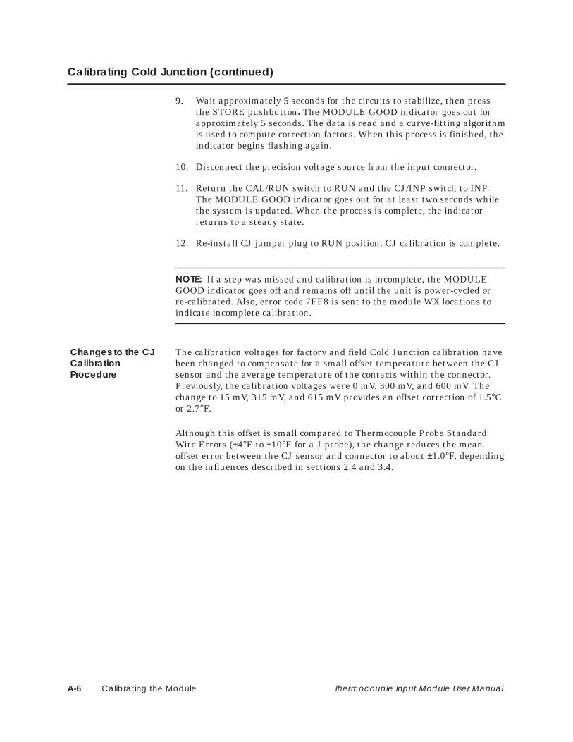
9. Wait approximately 5 seconds for the circuits to stabilize, then pressthe STORE pushbutton. The MODULE GOOD indicator goes out forapproximately 5 seconds. The data is read and a curve-fitting algorithmis used to compute correction factors. When this process is finished, theindicator begins flashing again.
10. Disconnect the precision voltage source from the input connector.
11. Return the CAL/RUN switch to RUN and the CJ/INP switch to INP.The MODULE GOOD indicator goes out for at least two seconds whilethe system is updated. When the process is complete, the indicatorreturns to a steady state.
12. Re-install CJ jumper plug to RUN position. CJ calibration is complete.
NOTE: If a step was missed and calibration is incomplete, the MODULEGOOD indicator goes off and remains off until the unit is power-cycled orre-calibrated. Also, error code 7FF8 is sent to the module WX locations toindicate incomplete calibration.
The calibration voltages for factory and field Cold Junction calibration havebeen changed to compensate for a small offset temperature between the CJsensor and the average temperature of the contacts within the connector.Previously, the calibration voltages were 0 mV, 300 mV, and 600 mV. Thechange to 15 mV, 315 mV, and 615 mV provides an offset correction of 1.5°Cor 2.7°F.
Although this offset is small compared to Thermocouple Probe StandardWire Errors (±4°F to ±10°F for a J probe), the change reduces the meanoffset error between the CJ sensor and connector to about ±1.0°F, dependingon the influences described in sections 2.4 and 3.4.
Changes to the CJCalibrationProcedure

Calibrating the Module A-7Thermocouple Input Module User Manual
Because the field connector does not have much thermal mass, atemperature gradient can exist, from top to bottom, from 0.4°F to as muchas 2.6°F, depending on forced air circulation, radiant heating, etc. The topterminals are usually warmer. The calibration procedure cannot account forthis on a channel-by-channel basis, so the Channel 5 terminals are used asan average reference for the following procedures.
Additional errors, typically less than ±0.2°F, can be caused by differences inthe connector terminal composition.
NOTE: Connector errors are not included in the published accuracyspecification; the direction and magnitude of these errors depend on theinstallation details. Refer to section 3.4.
Follow the steps below for calibration with an accurate, external method oftemperature measurement:
1. With the unit at “INSTALLED AMBIENT TEMPERATURE” and aprecision voltage source, perform the Input calibration procedure.
2. Use the former calibration voltages of 0 mV, 300 mV, and 600 mV, andperform the CJ calibration.
3. Install a jumper wire in the Channel 5 position.
4. With the unit operating in T/C mode and °C, record the PLC reading forthe Channel 5 position. This represents the temperature used for theCJ correction by the software.
5. Under the conditions of step 4., obtain the temperature of theChannel 5terminals with an external precision measurement systemin °C.
6. Determine the difference between the PLC reading for Channel 5 andthe externally measured temperature for the same connector terminals.
7. For each degree C difference, add 10.0 mV to the CJ voltages used instep 2. Perform the CJ calibration again.
For example, if the difference is determined to be 0.8°C, use 8 mV, 308mV, and 608 mV as the calibration voltages for the CJ procedure.
Field ConnectorErrors duringThermocoupleMeasurement
Higher PrecisionCalibration:Method 1

Calibrating the ModuleA-8 Thermocouple Input Module User Manual
Calibrating Cold Junction (continued)
The results from using this higher precision calibration, with an accurate,external method of temperature measurement, follow:
• Errors due to the temperature coefficients of the internal componentscan be reduced or eliminated by calibrating the unit at the “INSTALLEDAMBIENT TEMPERATURE.”
• The small error of the CJ sensor (guaranteed to be less than 0.5°C) isaccounted for by determining the CJ offset with steps 4. and 5.
• Step 5. provides for centering the CJ calibration within the temperaturegradient of the connector.
After this calibration has been completed, the errors internal to the moduleare less than ±50 V (±1.8°F for a J probe). To arrive at a worst-case error,consider:
• The variance within the connector of ±1.3°F, and
• The error from non-homogenous materials of ±0.2°F.
The result is a worst-case error of ±3.3°F, using a type J probe withmeasurements above 0°C.
Typical module error is within ±30 V (±1.1°F for a J probe). Thetemperature gradient within the connector is usually less than ±0.5°F.Therefore, the typical mean accuracy is ±1.6°F, after the precisioncalibration described above has been made.
Follow the steps below for calibration without an external method oftemperature measurement:
1. With the unit at “INSTALLED AMBIENT TEMPERATURE” and aprecision voltage source, perform the Input calibration procedure.
2. Use the newly published CJ calibration voltages of 15 mV, 315 mV, and615 mV to perform the CJ calibration.
Example of aWorst-Case Error
Typical MeanAccuracy
Higher PrecisionCalibration:Method 2

Calibrating the Module A-9Thermocouple Input Module User Manual
The results from using this higher precision calibration, without an externalmethod of temperature measurement, follow:
• Errors due to the temperature coefficients of the internal componentscan be reduced or eliminated by calibrating the unit at the “INSTALLEDAMBIENT TEMPERATURE.”
• Using the new CJ calibration voltages, the offset error between the CJsensor and the middle terminals of the connector should be less than±1.0°F.
After this calibration has been completed, the errors internal to the moduleare less than ±50 V (±1.8°F for a J probe). To arrive at a worst-case error,consider:
• The variance within the connector of ±1.3°F; and
• The error from non-homogenous materials of ±0.2°F; and
• ±1.0°F for the CJ connector terminals offset error.
The result is a worst-case error of ±4.3°F, using a type J probe withmeasurements above 0°C.
Typical module error is within ±30 V (±1.1°F for a J probe). Thetemperature gradient within the connector is usually less than ±0.5°F, andthe CJ to connector terminals offset error is ±1.0°F. Therefore, the typicalmean accuracy is ±2.6°F, after the precision calibration described above hasbeen made.
To determine the accuracy limits for Thermocouple Probe types (other thantype J), convert the ±50 V and ±30 V figures to temperature usingTable A-1.
NOTE: The CJ offset must be limited to about 3°C, or 30.0 mV. Greateroffsets are not feasible because they can create problems with the CJcalibration auto-ranging function. This CJ auto-ranging function allows theproduct to automatically recognize which of the three calibration voltages isbeing applied during calibration.
Example of aWorst-Case Error
Typical MeanAccuracy

Calibrating the ModuleA-10 Thermocouple Input Module User Manual
Calibrating Cold Junction (continued)
Table A-1 T/C Probe Output Characteristics
Probe Type Temperature (°C) Rate-of-change (µV/°C)
J Max 760 °C 64 µV / °C275 °C 55 µV / °C25 °C 52 µV / °C0 °C 50 µV / °C
Min –210 °C 20 µV / °C
K Max 1320 °C 35 µV / °C550 °C 43 µV / °C25 °C 40 µV / °C
0 °C 39 µV / °CMin –220 °C 12 µV / °C
T Max 400 °C 62 µV / °C85 °C 46 µV / °C25 °C 41 µV / °C
0 °C 39 µV / °CMin –230 °C 11 µV / °C
E Max 700 °C 80 µV / °C230 °C 75 µV / °C25 °C 61 µV / °C
0 °C 59 µV / °CMin –240 °C 13 µV / °C
R Max 1768 °C 12 µV / °C884 °C 12 µV / °C25 °C 6 µV / °C
Min 0 °C 5 µV / °C
S Max 1768 °C 11 µV / °C884 °C 11 µV / °C25 °C 6 µV / °C
Min 0 °C 5 µV / °C
N Max 1300 °C 36 µV / °C550 °C 39 µV / °C25 °C 27 µV / °C
0 °C 26 µV / °CMin –200 °C 10 µV / °C

Specifications B-1Thermocouple Input Module User Manual
Appendix B
Specifications
Table B-1 Environmental Specifications
Operating temperature 0° to 60°C (32° to 140°F)
Storage temperature –40° to 70°C (–40° to 158°F)
Relative humidity 5% to 95% noncondensing
Pollution degree 2, IEC 664, 664 A
Vibration: Sinusoidal
Random
IEC 68-2-6, Test Fc: 0.15 mm peak-to-peak,10–57 Hz;1.0 g, 57–150 Hz
NAVMAT P–9492 or IEC 68–2–34, Test Fdcwith 0.04 g2/Hz, 80–350 Hz, and 3 dB/octave rolloff,80–20 Hz and 350–2000 Hz at 10 min/axis
Impact shock IEC 68–2–27. Test Ea half sine, 15 g, 11 ms
Electrostatic discharge IEC 801, Part 2, Level 4, (15 kV)
Noise immunity
Conducted IEC 801, Part 4, Level 3
On user powerlines MIL STD 461B, CS01, CS02, CS06IEC 255-4, IEEE 472
Noise immunity
(Radiated) IEC 801, Part 3, Level 3MIL STD 461B, RS01, RS02, RS03
Corrosion protection All parts are corrosion-resistant or are plated orpainted as corrosion protection.
Torque for bezel screws 0.3 Nm (2.61 in.-lbs.) minimum0.6 Nm (5.22 in.-lbs.) maximum
Weight and dimensions ofpacked module
2 lbs., 9 oz; 12.75″ × 13.5″ × 3.75″
Weight and dimensions ofunpacked module
1 lb., 3 oz; 10.5″ × 8.0″ × 0.8″

SpecificationsB-2 Thermocouple Input Module User Manual
Table B-2 Electrical/Performance Specifications
Form factor 8 channels in single-wide Series 505 module.
Signal range –50 mV to +50 mV; full-scale range (FSR) of 100 mV.
TC input types J, K, T, E, R, S, N, mV; all channels same type,selected with dipswitch on circuit board.
Isolation (channel-channel) 1500 Vrms
Isolation (channel-PLC) 1500 Vrms
Input impedance >10 MΩ DC; 100 kΩ @ 60 Hz AC
Common-mode rejection >130 dB @ 50/60 Hz
Normal-mode rejection >100 dB @ 50/60 Hz
Input overvoltage Protected to 130 Vrms AC @ 50/60 Hz or 100 VDC.
Resolution 5 µV (0.005% of FSR) typical; 14-bit minimum
Repeatability ±10 µV (±0.01% of FSR) typical
Overall accuracy ±40 µV (±0.04% of FSR) typical at 25°C ambientwith 100 ppm/°C temperature coefficient
Update/sampling time 250 ms for one or all channels. Data are processedas four-sample running average providing superiorrepeatability. Step response time to 98% of finalvalue < 1.5 seconds.
Upscale error reporting Thermocouple burnout and other errors reported toPLC. Typical open probe response less than 1minute.
Cold junction compensation Automatic; can be calibrated independently.
Input signal wiring 12–26 AWG or 0.16–3.2 mm2
Module power from base 2.2 W max (1.6W typical) of +5 V, and 0.01 W of –5 V
Data formatting options Engineering units (±10000 for mV, and °C×10 or°F×10 for thermocouple); scaled integer (±32000 formV, and 0 to 32000 for thermocouple); selectionmade with dipswitch on circuit board, all channelssame

Index-1
Index
" (2 **,)0&- 0$$
--$-.(
)(..$(" !), 0$$. & *#)($(" !), 4
&$,.$)(!&)1#,. 4
*, &$'$(,2 -. *- 454- ..$(" $*-1$.# - 4
/- , 4
)& %/(.$)(
#(" - $( &$,.$)( *,) /, 4!$ & )(( .), ,,),- 454
#$"# , *, $-$)( &$,.$)( 454
)& %/(.$)( )'* (-.$)( 4
)(.,)&& , *,)",''$("*,)",''$(" 0$ - 4-'*& !$(.$)( #,. 4
/*.$(" ')/& )(!$"/,.$)( . 4
.' -/,$(" '$&&$0)&.- 41), !),'. 4
. -'*&$(" ,. ( &$( ,$3.$)( 4
$*-1$.# -
&).$)( )! 4- & .$(" ("$( ,$(" ), -&$(" 4
- ..$(" 33 4- ..$(" ", - ), 4
- ..$(" !), &$,.$)( 4- ..$(" $(*/. ), )& %/(.$)( 4
- ..$(" $(*/. .2* 4- ..$(" 4
(*/. 1$, -)(( .$(" 4$(*/. )(( .), 4/- , 1$, . ,'$(.$)(- 4 4
(*/.- &$,.$(" 4
$&&$0)&.- )* ,.$(" #,. ,$-.$- 4
)/& ! ./, - 4 4#(&$(" 4$(-* .$(" 4$(-.&&.$)( !&)1#,. 4$(-.&&$(" 4*)1 , , +/$, ' (.- 4.$"#. ($(" -, 1- 4
0 ,0$ 1&$,.$)( 4" ( ,& -,$*.$)( 4$(-.&&.$)( 454')/& * ,!),'( 4)*.$)( - ..$(" 4*&$(" ')/& $( )* ,.$)( 4.,)/& -#)).$(" 454
,!),'( . .# ,'))/*& 4
)1 , /" . 4
)1 , , +/$, ' (.- 4
,) /,2 )! 4 .2* - 4
,) )/.*/. #,. ,$-.$- 4
,) .2* . '* ,./, ,(" - 4

Index-2
! ! &#! &
!! !!% &
$! ! " & ! $! &
" !" !# ! ! &
$ &
$! $
$ &
!! &
$!"! $ &
"! ! &
" !! & &

% &$ $ " !%
$% $% ! $ &$ $% " !% !'%&$ '&" &"! !
! $ $%&$ &$ $% " !&$!&"! '%!%% !% "$#
% &$ $ " )% !%&$' !&% !"$#"$&
% $%&$ &$ $ " !$($&$% "$&"$%

Customer Registration
We would like to know what you think about our user manuals so that we can serve you better.How would you rate the quality of our manuals?
Excellent Good Fair Poor
AccuracyOrganizationClarityCompletenessOverall designSizeIndex
Would you be interested in giving us more detailed comments about our manuals?
Yes! Please send me a questionnaire.
No. Thanks anyway.
Your Name:
Title:
Telephone Number: ( )
Company Name:
Company Address:
Manual Name: SIMATIC TI505 Thermocouple Input Module User Manual Edition: Third
Manual Assembly Number: 2586546-0037 Date: 05/94
Order Number: PPX:505–8111–3

BUSINESS REPLY MAILFIRST CLASS PERMIT NO.3 JOHNSON CITY, TN
FOLD
FOLD
POSTAGE WILL BE PAID BY ADDRESSEE
NO POSTAGENECESSARYIF MAILED
IN THEUNITED STATES
SIEMENS INDUSTRIAL AUTOMATION, INC. 3000 BILL GARLAND RD.P.O. BOX 1255JOHNSON CITY TN 37605–1255
ATTN: Technical Communications M/S 3519
Top Related