


Languages
Pages
Legal


1
©Silberschatz, Korth and Sudarshan1.1Database System Concepts
Chapter 19: Distributed DatabasesChapter 19: Distributed Databases
Heterogeneous and Homogeneous Databases
Distributed Data Storage Distributed Transactions Commit Protocols Concurrency Control in Distributed Databases Availability Distributed Query Processing Heterogeneous Distributed Databases Directory Systems
2
©Silberschatz, Korth and Sudarshan1.2Database System Concepts
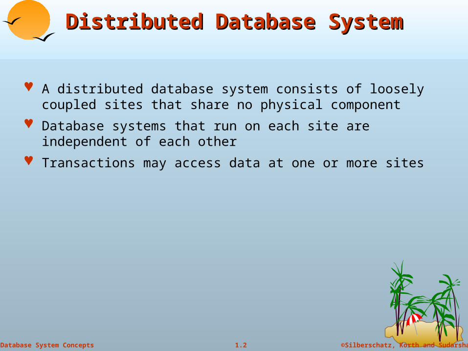
Distributed Database SystemDistributed Database System
A distributed database system consists of loosely coupled sites that share no physical component
Database systems that run on each site are independent of each other
Transactions may access data at one or more sites

3
©Silberschatz, Korth and Sudarshan1.3Database System Concepts
Homogeneous Distributed DatabasesHomogeneous Distributed Databases
In a homogeneous distributed database All sites have identical software Are aware of each other and agree to cooperate in processing user
requests. Each site surrenders part of its autonomy in terms of right to change
schemas or software Appears to user as a single system
In a heterogeneous distributed database Different sites may use different schemas and software
Difference in schema is a major problem for query processing Difference in software is a major problem for transaction
processing Sites may not be aware of each other and may provide only
limited facilities for cooperation in transaction processing

4
©Silberschatz, Korth and Sudarshan1.4Database System Concepts
Distributed Data StorageDistributed Data Storage
Assume relational data model
Replication System maintains multiple copies of data, stored in different sites,
for faster retrieval and fault tolerance.
Fragmentation Relation is partitioned into several fragments stored in distinct sites
Replication and fragmentation can be combined Relation is partitioned into several fragments: system maintains
several identical replicas of each such fragment.
5
©Silberschatz, Korth and Sudarshan1.5Database System Concepts
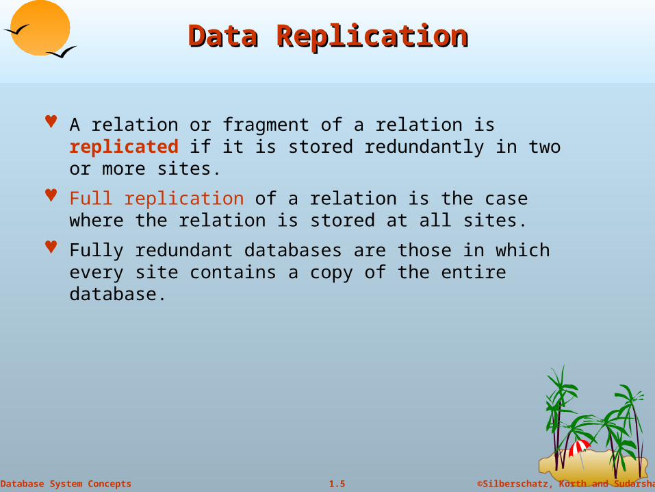
Data ReplicationData Replication
A relation or fragment of a relation is replicated if it is stored redundantly in two or more sites.
Full replication of a relation is the case where the relation is stored at all sites.
Fully redundant databases are those in which every site contains a copy of the entire database.
6
©Silberschatz, Korth and Sudarshan1.6Database System Concepts
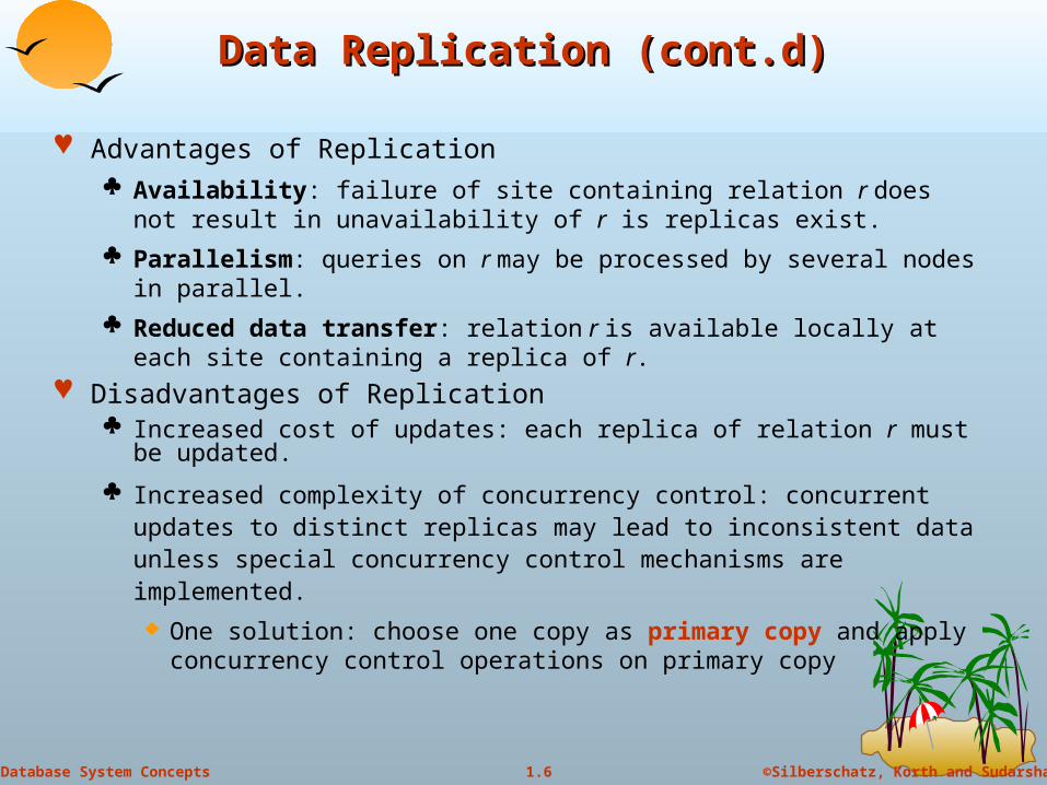
Data Replication (cont.d)Data Replication (cont.d)
Advantages of Replication Availability: failure of site containing relation r does not result in
unavailability of r is replicas exist.
Parallelism: queries on r may be processed by several nodes in parallel.
Reduced data transfer: relation r is available locally at each site containing a replica of r.
Disadvantages of Replication Increased cost of updates: each replica of relation r must be updated.
Increased complexity of concurrency control: concurrent updates to distinct replicas may lead to inconsistent data unless special concurrency control mechanisms are implemented.
One solution: choose one copy as primary copy and apply concurrency control operations on primary copy

7
©Silberschatz, Korth and Sudarshan1.7Database System Concepts
Data FragmentationData Fragmentation
Division of relation r into fragments r1, r2, …, rn which contain sufficient information to reconstruct relation r.
Horizontal fragmentation: each tuple of r is assigned to one or more fragments
Vertical fragmentation: the schema for relation r is split into several smaller schemas All schemas must contain a common candidate key (or superkey) to
ensure lossless join property.
A special attribute, the tuple-id attribute may be added to each schema to serve as a candidate key.
Example : relation account with following schema
Account-schema = (branch-name, account-number, balance)
8
©Silberschatz, Korth and Sudarshan1.8Database System Concepts
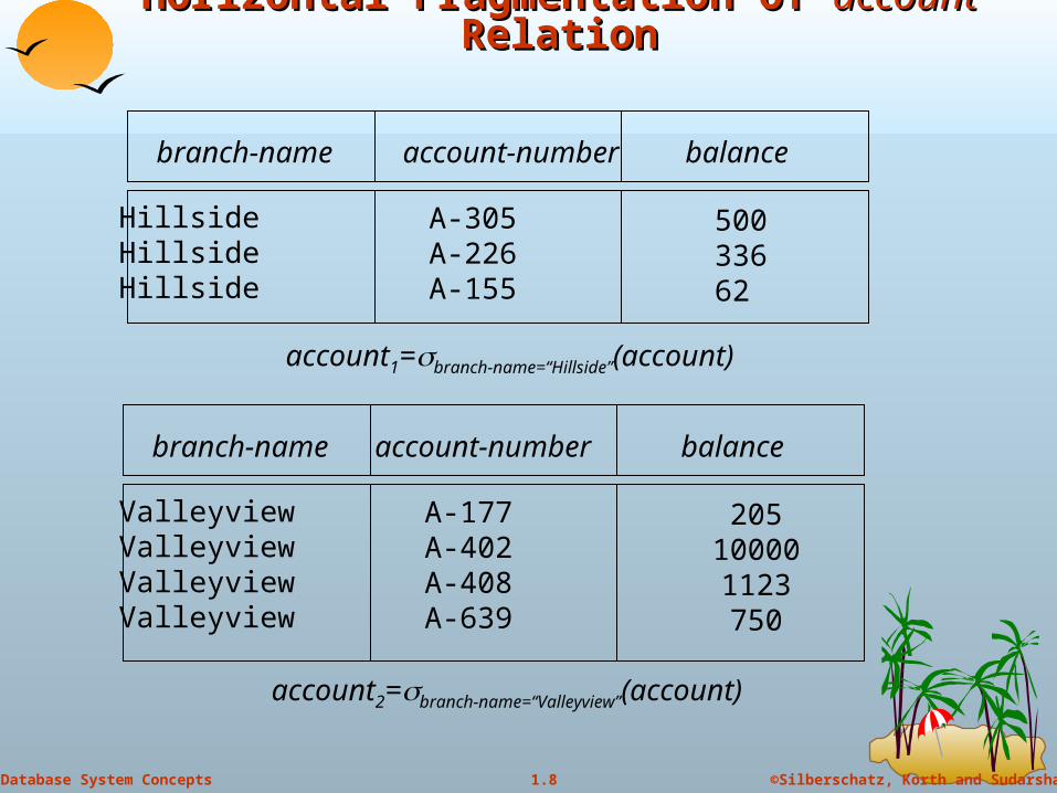
Horizontal Fragmentation of Horizontal Fragmentation of accountaccount Relation Relation
branch-name account-number balance
HillsideHillsideHillside
A-305A-226A-155
50033662
account1=branch-name=“Hillside”(account)
branch-name account-number balance
ValleyviewValleyviewValleyviewValleyview
A-177A-402A-408A-639
205100001123750
account2=branch-name=“Valleyview”(account)
9
©Silberschatz, Korth and Sudarshan1.9Database System Concepts
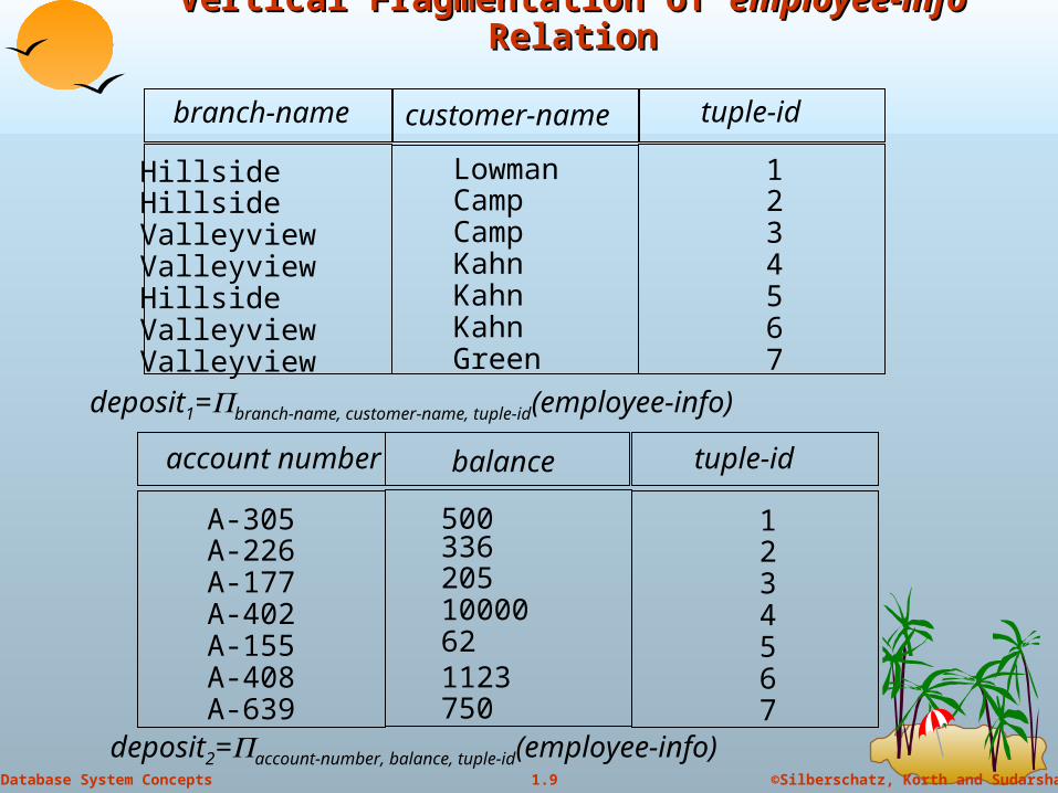
Vertical Fragmentation of Vertical Fragmentation of employee-info employee-info RelationRelation
branch-name customer-name tuple-id
HillsideHillsideValleyviewValleyviewHillsideValleyviewValleyview
LowmanCampCampKahnKahnKahnGreen
deposit1=branch-name, customer-name, tuple-id(employee-info)
1234567
account number balance tuple-id
50033620510000621123750
1234567
A-305A-226A-177A-402A-155A-408A-639
deposit2=account-number, balance, tuple-id(employee-info)
10
©Silberschatz, Korth and Sudarshan1.10Database System Concepts
Advantages of FragmentationAdvantages of Fragmentation
Horizontal: allows processing of fragments of a relation in parallel
allows a relation to be split so that tuples are located where they are most frequently accessed
Vertical:
allows tuples to be split so that each part of the tuple is stored where it is most frequently accessed
tuple-id attribute allows efficient joining of vertical fragments
allows parallel processing on a relation
Vertical and horizontal fragmentation can be mixed. Fragments may be successively fragmented to an arbitrary depth.
11
©Silberschatz, Korth and Sudarshan1.11Database System Concepts
Data TransparencyData Transparency
Data transparency: Degree to which system user may remain unaware of the details of how and where the data items are stored in a distributed system
Consider transparency issues in relation to: Fragmentation transparency
Replication transparency
Location transparency

12
©Silberschatz, Korth and Sudarshan1.12Database System Concepts
Naming of Data Items - CriteriaNaming of Data Items - Criteria
1. Every data item must have a system-wide unique name.
2. It should be possible to find the location of data items efficiently.
3. It should be possible to change the location of data items transparently.
4. Each site should be able to create new data items autonomously.
13
©Silberschatz, Korth and Sudarshan1.13Database System Concepts
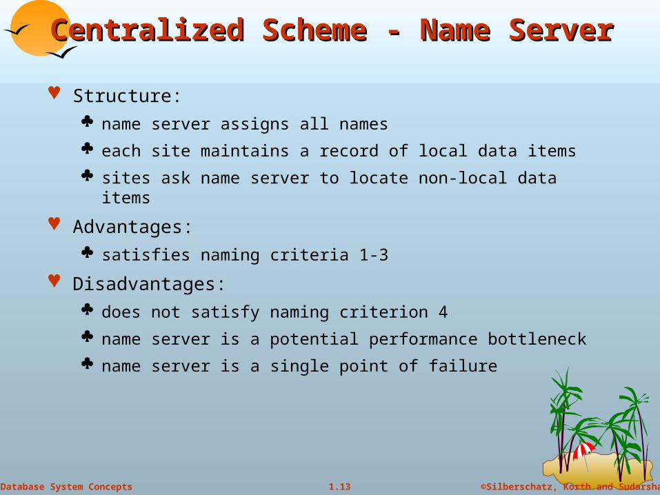
Centralized Scheme - Name ServerCentralized Scheme - Name Server
Structure: name server assigns all names
each site maintains a record of local data items
sites ask name server to locate non-local data items
Advantages: satisfies naming criteria 1-3
Disadvantages: does not satisfy naming criterion 4
name server is a potential performance bottleneck
name server is a single point of failure

14
©Silberschatz, Korth and Sudarshan1.14Database System Concepts
Use of AliasesUse of Aliases
Alternative to centralized scheme: each site prefixes its own site identifier to any name that it generates i.e., site 17.account. Fulfills having a unique identifier, and avoids problems associated
with central control.
However, fails to achieve network transparency.
Solution: Create a set of aliases for data items; Store the mapping of aliases to the real names at each site.
The user can be unaware of the physical location of a data item, and is unaffected if the data item is moved from one site to another.
Copyright: Silberschatz, Korth and Sudarhan
15
Distributed TransactionsDistributed Transactions
16
©Silberschatz, Korth and Sudarshan1.16Database System Concepts
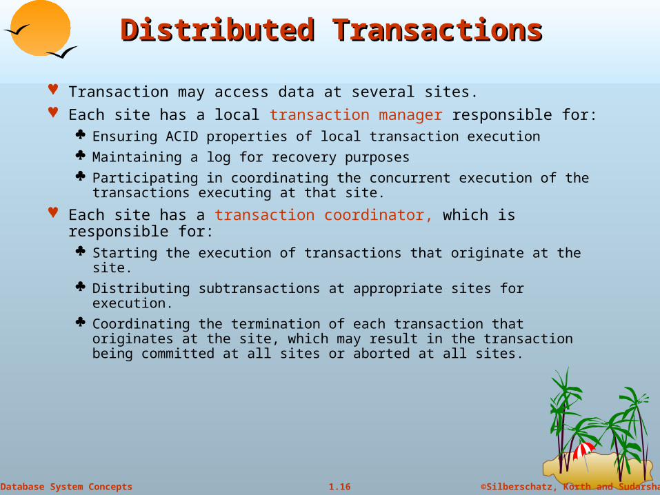
Distributed TransactionsDistributed Transactions
Transaction may access data at several sites. Each site has a local transaction manager responsible for:
Ensuring ACID properties of local transaction execution Maintaining a log for recovery purposes Participating in coordinating the concurrent execution of the
transactions executing at that site.
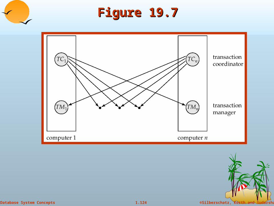
Each site has a transaction coordinator, which is responsible for: Starting the execution of transactions that originate at the site. Distributing subtransactions at appropriate sites for execution. Coordinating the termination of each transaction that originates at
the site, which may result in the transaction being committed at all sites or aborted at all sites.
18
©Silberschatz, Korth and Sudarshan1.18Database System Concepts
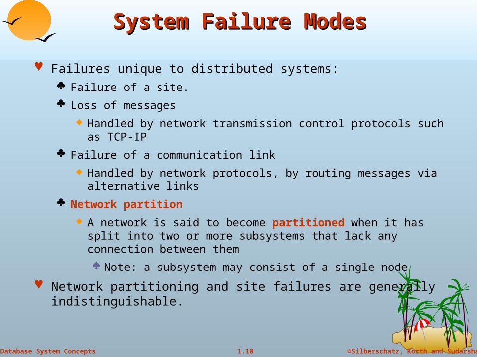
System Failure ModesSystem Failure Modes
Failures unique to distributed systems: Failure of a site.
Loss of messages
Handled by network transmission control protocols such as TCP-IP
Failure of a communication link
Handled by network protocols, by routing messages via alternative links
Network partition
A network is said to become partitioned when it has split into two or more subsystems that lack any connection between them
Note: a subsystem may consist of a single node
Network partitioning and site failures are generally indistinguishable.
19
©Silberschatz, Korth and Sudarshan1.19Database System Concepts
Commit ProtocolsCommit Protocols
Commit protocols are used to ensure atomicity across sites a transaction which executes at multiple sites must either be
committed at all the sites, or aborted at all the sites.
not acceptable to have a transaction committed at one site and aborted at another
The two-phase commit (2 PC) protocol is widely used
The three-phase commit (3 PC) protocol is more complicated and more expensive, but avoids some drawbacks of two-phase commit protocol. Less used.
20
©Silberschatz, Korth and Sudarshan1.20Database System Concepts
Two Phase Commit Protocol (2PC)Two Phase Commit Protocol (2PC)
Assumes fail-stop model – failed sites simply stop working, and do not cause any other harm, such as sending incorrect messages to other sites.
Execution of the protocol is initiated by the coordinator after the last step of the transaction has been reached.
The protocol involves all the local sites at which the transaction executed
Let T be a transaction initiated at site Si, and let the transaction coordinator at Si be Ci

21
©Silberschatz, Korth and Sudarshan1.21Database System Concepts
Phase 1: Obtaining a DecisionPhase 1: Obtaining a Decision
Coordinator asks all participants to prepare to commit transaction Ti.
Ci adds the records <prepare T> to the log and forces log to stable storage
sends prepare T messages to all sites at which T executed
Upon receiving message, transaction manager at site determines if it can commit the transaction
if not, add a record <no T> to the log and send abort T message to Ci
if the transaction can be committed, then:
add the record <ready T> to the log
force all records for T to stable storage
send ready T message to Ci
22
©Silberschatz, Korth and Sudarshan1.22Database System Concepts
Phase 2: Recording the DecisionPhase 2: Recording the Decision
T can be committed of Ci received a ready T message from all the participating sites: otherwise T must be aborted.
Coordinator adds a decision record, <commit T> or <abort T>, to the log and forces record onto stable storage. Once the record is in stable storage it becomes irrevocable within this transaction (even if failures occur)
Coordinator sends a message to each participant informing it of the decision (commit or abort), possibly for all active transactions
Participants take appropriate action locally.

23
©Silberschatz, Korth and Sudarshan1.23Database System Concepts
Handling of Failures - Site FailureHandling of Failures - Site Failure
When site Si recovers, it examines its log to determine the fate of
transactions active at the time of the failure.
Log contain <commit T> record: site executes redo (T)
Log contains <abort T> record: site executes undo (T)
Log contains <ready T> record: site must consult Ci to determine the fate of T.
If Ci says T committed, redo (T)
If Ci says T aborted, undo (T)
The log contains no control records concerning T implies that Sk failed before responding to the prepare T message from Ci
since the failure of Sk precludes the earlier sending of a commitresponse, Ci must abort T
Sk must execute undo (T)

24
©Silberschatz, Korth and Sudarshan1.24Database System Concepts
Handling of Failures- Coordinator FailureHandling of Failures- Coordinator Failure
If coordinator fails while the commit protocol for T is executing then other participating sites must decide on T’s fate:
1. If an active site contains a <commit T> record in its log, then T must be committed.
2. If an active site contains an <abort T> record in its log, then T must be aborted (rolled back).
3. If some active participating site does not contain a <ready T> record in its log, then the failed coordinator Ci cannot have decided to commit T. Can therefore abort T.
4. If none of the above cases holds, then all active sites must have a <ready T> record in their logs, but no additional control records (such as <abort T> of <commit T>). In this case active sites must wait for Ci to recover, to find decision.
Blocking problem : active sites may have to wait for failed coordinator to recover.

25
©Silberschatz, Korth and Sudarshan1.25Database System Concepts
Handling of Failures - Network PartitionHandling of Failures - Network Partition
If the coordinator and all its participants remain in one partition, the failure has no effect on the commit protocol.
If the coordinator and its participants belong to different partitions: Sites that are not in the partition containing the coordinator think the
coordinator has failed, and execute the protocol to deal with failure of the coordinator.
No harm results, but sites may still have to wait for decision from coordinator.
The coordinator and the sites in the same partition as the coordinator think that the sites in the other partition have failed, and follow the usual 2-phase commit protocol.
Again, no harm results
26
©Silberschatz, Korth and Sudarshan1.26Database System Concepts
Recovery and Concurrency ControlRecovery and Concurrency Control
In-doubt transactions have a <ready T>, but neither a <commit T>, nor an <abort T> log record.
The recovering site must determine the commit-abort status of such transactions by contacting other sites; this can slow and potentially block recovery.
Recovery algorithms can note lock information in the log: Instead of <ready T>, write out <ready T, L> L = list of locks held by
T when the log is written (read locks can be omitted).
For every in-doubt transaction T, all the locks noted in the <ready T, L> log record are reacquired.
After lock reacquisition, transaction processing can resume; the commit or rollback of in-doubt transactions is performed concurrently with the execution of new transactions.

27
©Silberschatz, Korth and Sudarshan1.27Database System Concepts
Three Phase Commit (3PC)Three Phase Commit (3PC)
Assumptions: No network partitioning At any point, at least one site must be up. At most K sites (participants as well as coordinator) can fail
Phase 1: Obtaining Preliminary Decision: Identical to 2PC Phase 1. Every site is ready to commit if instructed to do so
Phase 2 of 2PC is split into 2 phases, Phase 2 and Phase 3 of 3PC In phase 2 coordinator makes a decision as in 2PC (called the pre-commit
decision) and records it in multiple (at least K) sites In phase 3, coordinator sends commit/abort message to all participating sites,
Under 3PC, knowledge of pre-commit decision can be used to commit despite coordinator failure Avoids blocking problem as long as < K sites fail
Drawbacks: higher overheads assumptions may not be satisfied in practice
Won’t study it further here

28
©Silberschatz, Korth and Sudarshan1.28Database System Concepts
Alternative Models of Transaction Alternative Models of Transaction ProcessingProcessing
Notion of a single transaction spanning multiple sites is inappropriate for many applications E.g. transaction crossing an organizational boundary Few organizations would permit an externally initiated transaction to
block local transactions for an indeterminate period
Alternative models carry out transactions by sending messages Code to handle messages must be carefully designed to ensure
atomicity and durability properties for updates Isolation cannot be guaranteed, in that intermediate stages are
visible, but code must ensure no inconsistent states result due to concurrency
Persistent messaging systems are systems that provide transactional properties to messages Messages are guaranteed to be delivered exactly once Need to discuss implementation techniques
29
©Silberschatz, Korth and Sudarshan1.29Database System Concepts
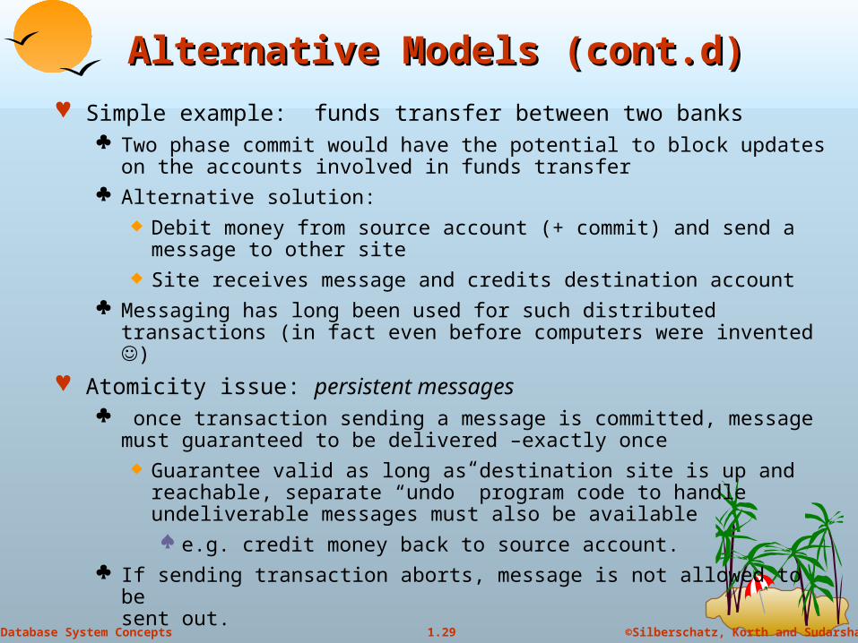
Alternative Models (cont.d)Alternative Models (cont.d)
Simple example: funds transfer between two banks Two phase commit would have the potential to block updates on the
accounts involved in funds transfer Alternative solution:
Debit money from source account (+ commit) and send a message to other site
Site receives message and credits destination account Messaging has long been used for such distributed transactions (in fact
even before computers were invented )
Atomicity issue: persistent messages once transaction sending a message is committed, message must
guaranteed to be delivered –exactly once Guarantee valid as long as destination site is up and reachable,
separate “undo” program code to handle undeliverable messages must also be available e.g. credit money back to source account.
If sending transaction aborts, message is not allowed to be sent out.

30
©Silberschatz, Korth and Sudarshan1.30Database System Concepts
Error Conditions with Persistent Error Conditions with Persistent MessagingMessaging
Code to handle messages has to take care of variety of “semantic” failure situations (even assuming guaranteed message delivery) E.g. if destination account does not exist, failure message must be
sent back to source site When failure message is received from destination site, or
destination site itself does not exist, money must be deposited back in source account Problem e.g. if source account has been closed…
get humans to take care of problem
User code executing transaction processing using 2PC does not have to deal with such failures
There are many situations where extra effort of error handling is worth the benefit of absence of blocking E.g. pretty much all transactions that go across organizations
31
©Silberschatz, Korth and Sudarshan1.31Database System Concepts
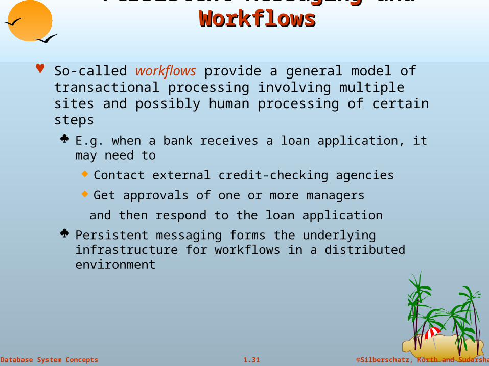
Persistent Messaging and WorkflowsPersistent Messaging and Workflows
So-called workflows provide a general model of transactional processing involving multiple sites and possibly human processing of certain steps E.g. when a bank receives a loan application, it may need to
Contact external credit-checking agencies
Get approvals of one or more managers
and then respond to the loan application
Persistent messaging forms the underlying infrastructure for workflows in a distributed environment
32
©Silberschatz, Korth and Sudarshan1.32Database System Concepts
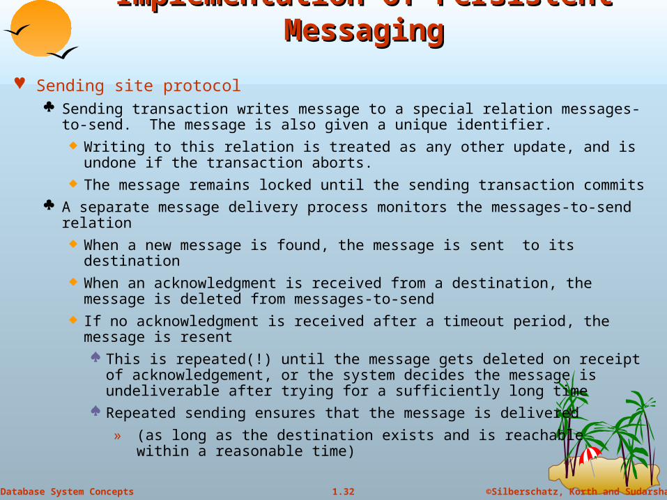
Implementation of Persistent MessagingImplementation of Persistent Messaging
Sending site protocol Sending transaction writes message to a special relation messages-to-send.
The message is also given a unique identifier. Writing to this relation is treated as any other update, and is undone if the
transaction aborts. The message remains locked until the sending transaction commits
A separate message delivery process monitors the messages-to-send relation When a new message is found, the message is sent to its destination When an acknowledgment is received from a destination, the message is
deleted from messages-to-send If no acknowledgment is received after a timeout period, the message is
resent This is repeated(!) until the message gets deleted on receipt of
acknowledgement, or the system decides the message is undeliverable after trying for a sufficiently long time
Repeated sending ensures that the message is delivered
» (as long as the destination exists and is reachable within a reasonable time)
33
©Silberschatz, Korth and Sudarshan1.33Database System Concepts
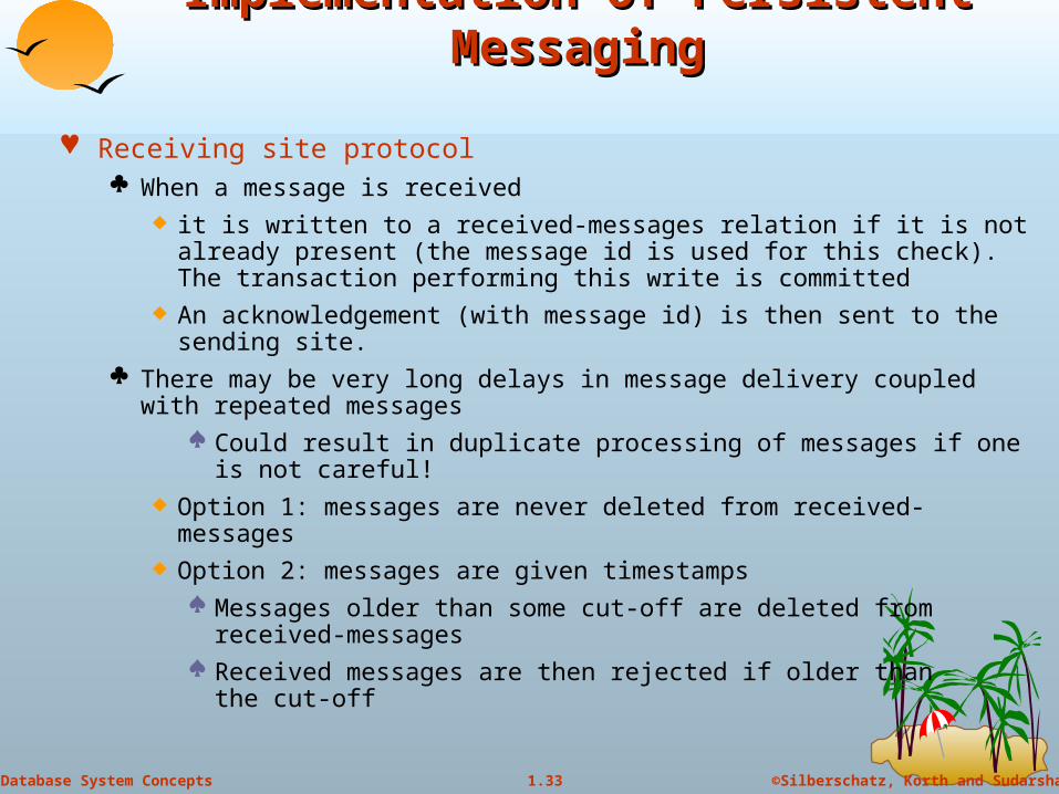
Implementation of Persistent MessagingImplementation of Persistent Messaging
Receiving site protocol When a message is received
it is written to a received-messages relation if it is not already present (the message id is used for this check). The transaction performing this write is committed
An acknowledgement (with message id) is then sent to the sending site. There may be very long delays in message delivery coupled with repeated
messages Could result in duplicate processing of messages if one is not
careful! Option 1: messages are never deleted from received-messages Option 2: messages are given timestamps
Messages older than some cut-off are deleted from received-messages
Received messages are then rejected if older than the cut-off

Copyright: Silberschatz, Korth and Sudarhan
34
Concurrency Control in Distributed Concurrency Control in Distributed DatabasesDatabases
35
©Silberschatz, Korth and Sudarshan1.35Database System Concepts
Concurrency ControlConcurrency Control
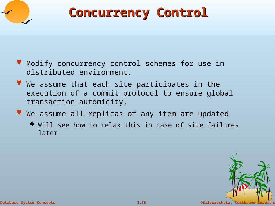
Modify concurrency control schemes for use in distributed environment.
We assume that each site participates in the execution of a commit protocol to ensure global transaction automicity.
We assume all replicas of any item are updated Will see how to relax this in case of site failures later
36
©Silberschatz, Korth and Sudarshan1.36Database System Concepts
Single- Lock- Manager ApproachSingle- Lock- Manager Approach
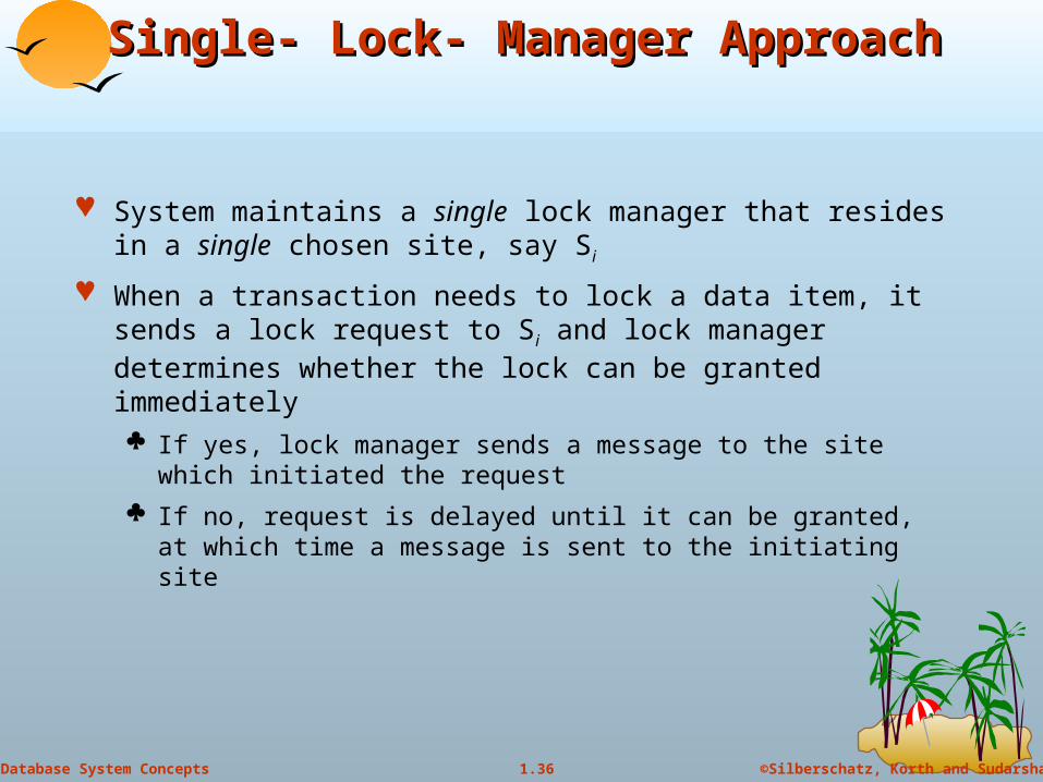
System maintains a single lock manager that resides in a single chosen site, say Si
When a transaction needs to lock a data item, it sends a lock request to Si and lock manager determines whether the lock can be granted immediately If yes, lock manager sends a message to the site which initiated the
request
If no, request is delayed until it can be granted, at which time a message is sent to the initiating site

37
©Silberschatz, Korth and Sudarshan1.37Database System Concepts
Single- Lock- Manager Approach Single- Lock- Manager Approach (cont.d)(cont.d)
The transaction can read the data item from any one of the sites at which a replica of the data item resides.
Writes must be performed on all replicas of a data item
Advantages of scheme: Simple implementation
Simple deadlock handling
Disadvantages of scheme are: Bottleneck: lock manager site becomes a bottleneck
Vulnerability: system is vulnerable to lock manager site failure.

38
©Silberschatz, Korth and Sudarshan1.38Database System Concepts
Distributed Lock ManagerDistributed Lock Manager
In this approach, functionality of locking is implemented by lock managers at each site Lock managers control access to local data items
But special protocols may be used for replicas
Advantage: work is distributed and can be made robust to failures
Disadvantage: deadlock detection is more complicated Lock managers cooperate for deadlock detection
Several variants of this approach Primary copy Majority protocol Biased protocol Quorum consensus
39
©Silberschatz, Korth and Sudarshan1.39Database System Concepts
Primary CopyPrimary Copy
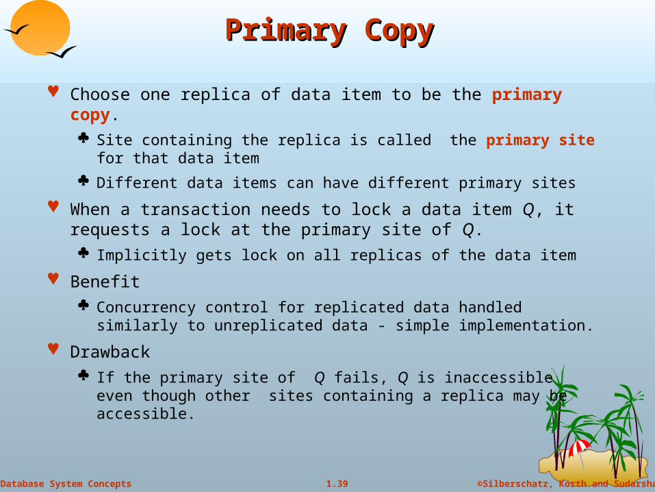
Choose one replica of data item to be the primary copy. Site containing the replica is called the primary site for that data
item
Different data items can have different primary sites
When a transaction needs to lock a data item Q, it requests a lock at the primary site of Q. Implicitly gets lock on all replicas of the data item
Benefit Concurrency control for replicated data handled similarly to
unreplicated data - simple implementation.
Drawback If the primary site of Q fails, Q is inaccessible even though other
sites containing a replica may be accessible.

40
©Silberschatz, Korth and Sudarshan1.40Database System Concepts
Majority ProtocolMajority Protocol
Local lock manager at each site administers lock and unlock requests for data items stored at that site.
When a transaction wishes to lock an unreplicated data item Q residing at site Si, a message is sent to Si ‘s lock manager.
If Q is locked in an incompatible mode, then the request is delayed until it can be granted.
When the lock request can be granted, the lock manager sends a message back to the initiator indicating that the lock request has been granted.

41
©Silberschatz, Korth and Sudarshan1.41Database System Concepts
Majority Protocol (cont.d)Majority Protocol (cont.d)
In case of replicated data If Q is replicated at n sites, then a lock request message must be
sent to more than half of the n sites in which Q is stored. The transaction does not operate on Q until it has obtained a lock on
a majority of the replicas of Q. When writing the data item, transaction performs writes on all
replicas.
Benefit Can be used even when some sites are unavailable
details on how handle writes in the presence of site failure later
Drawback Requires 2(n/2 + 1) messages for handling lock requests, and (n/2 +
1) messages for handling unlock requests. Potential for deadlock even with single item - e.g., each of 3
transactions may have locks on 1/3rd of the replicas of a data.
42
©Silberschatz, Korth and Sudarshan1.42Database System Concepts
Biased ProtocolBiased Protocol
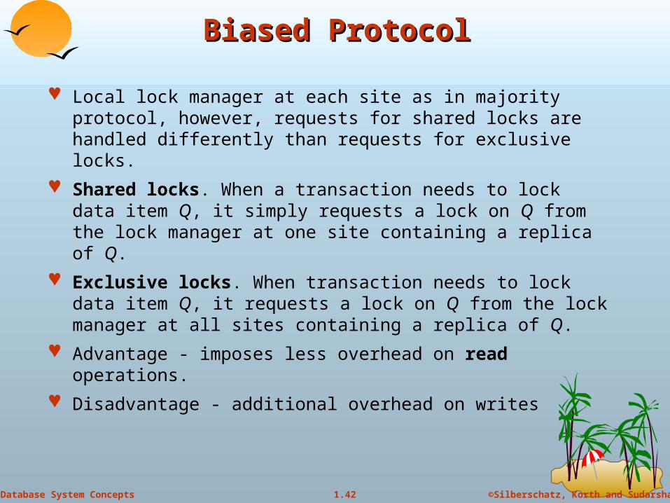
Local lock manager at each site as in majority protocol, however, requests for shared locks are handled differently than requests for exclusive locks.
Shared locks. When a transaction needs to lock data item Q, it simply requests a lock on Q from the lock manager at one site containing a replica of Q.
Exclusive locks. When transaction needs to lock data item Q, it requests a lock on Q from the lock manager at all sites containing a replica of Q.
Advantage - imposes less overhead on read operations.
Disadvantage - additional overhead on writes

43
©Silberschatz, Korth and Sudarshan1.43Database System Concepts
Quorum Consensus ProtocolQuorum Consensus Protocol
A generalization of both majority and biased protocols
Each site is assigned a weight. Let S be the total of all site weights
Choose two values read quorum Qr and write quorum Qw
Such that Qr + Qw > S and 2 * Qw > S
Quorums can be chosen (and S computed) separately for each item
Each read must lock enough replicas that the sum of the site weights is >= Qr
Each write must lock enough replicas that the sum of the site weights is >= Qw
For now we assume all replicas are written Extensions to allow some sites to be unavailable described later
44
©Silberschatz, Korth and Sudarshan1.44Database System Concepts
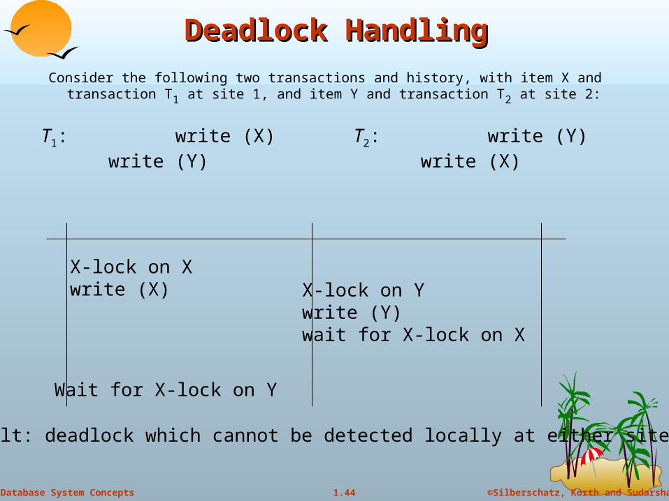
Deadlock HandlingDeadlock Handling
Consider the following two transactions and history, with item X and transaction T1 at site 1, and item Y and transaction T2 at site 2:
T1: write (X)write (Y)
T2: write (Y)write (X)
X-lock on Xwrite (X) X-lock on Y
write (Y)wait for X-lock on X
Wait for X-lock on Y
Result: deadlock which cannot be detected locally at either site

45
©Silberschatz, Korth and Sudarshan1.45Database System Concepts
Centralized ApproachCentralized Approach
A global wait-for graph is constructed and maintained in a single site; the deadlock-detection coordinator Real graph: Real, but unknown, state of the system.
Constructed graph:Approximation generated by the controller during the execution of its algorithm .
the global wait-for graph can be constructed when: a new edge is inserted in or removed from one of the local wait-for
graphs.
a number of changes have occurred in a local wait-for graph.
the coordinator needs to invoke cycle-detection.
If the coordinator finds a cycle, it selects a victim and notifies all sites. The sites roll back the victim transaction.

46
©Silberschatz, Korth and Sudarshan1.46Database System Concepts
Local and Global Wait-For GraphsLocal and Global Wait-For Graphs
Local
Global
47
©Silberschatz, Korth and Sudarshan1.47Database System Concepts
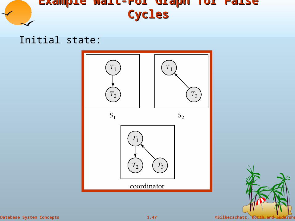
Example Wait-For Graph for False CyclesExample Wait-For Graph for False Cycles
Initial state:
48
©Silberschatz, Korth and Sudarshan1.48Database System Concepts
False Cycles (cont.d)False Cycles (cont.d)
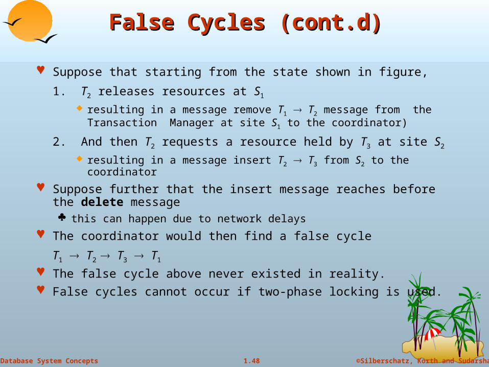
Suppose that starting from the state shown in figure,
1. T2 releases resources at S1 resulting in a message remove T1 T2 message from the
Transaction Manager at site S1 to the coordinator)
2. And then T2 requests a resource held by T3 at site S2 resulting in a message insert T2 T3 from S2 to the coordinator
Suppose further that the insert message reaches before the delete message this can happen due to network delays
The coordinator would then find a false cycle
T1 T2 T3 T1
The false cycle above never existed in reality. False cycles cannot occur if two-phase locking is used.
49
©Silberschatz, Korth and Sudarshan1.49Database System Concepts
Unnecessary RollbacksUnnecessary Rollbacks
Unnecessary rollbacks may result when deadlock has indeed occurred and a victim has been picked, and meanwhile one of the transactions was aborted for reasons unrelated to the deadlock.
Unnecessary rollbacks can result from false cycles in the global wait-for graph; however, likelihood of false cycles is low.

50
©Silberschatz, Korth and Sudarshan1.50Database System Concepts
TimestampingTimestamping
Timestamp based concurrency-control protocols can be used in distributed systems
Each transaction must be given a unique timestamp
Main problem: how to generate a timestamp in a distributed fashion Each site generates a unique local timestamp using either a logical
counter or the local clock.
Global unique timestamp is obtained by concatenating the unique local timestamp with the unique identifier.
51
©Silberschatz, Korth and Sudarshan1.51Database System Concepts
Timestamping (cont.d)Timestamping (cont.d)
A site with a slow clock will assign smaller timestamps Still logically correct: serializability not affected
But: “disadvantages” transactions
To fix this problem
Define within each site Si a logical clock (LCi), which generates the unique local timestamp
Require that Si advance its logical clock whenever a request is received from a transaction Ti with timestamp < x,y> and x is greater that the current value of LCi.
In this case, site Si advances its logical clock to the value x + 1.

52
©Silberschatz, Korth and Sudarshan1.52Database System Concepts
Replication with Weak ConsistencyReplication with Weak Consistency
Many commercial databases support replication of data with weak degrees of consistency (I.e., without a guarantee of serializabiliy)
E.g.: master-slave replication: updates are performed at a single “master” site, and propagated to “slave” sites. Propagation is not part of the update transaction: its is decoupled
May be immediately after transaction commits May be periodic
Data may only be read at slave sites, not updated No need to obtain locks at any remote site
Particularly useful for distributing information E.g. from central office to branch-office
Also useful for running read-only queries offline from the main database

53
©Silberschatz, Korth and Sudarshan1.53Database System Concepts
Replication with Weak Consistency (cont.d)Replication with Weak Consistency (cont.d)
Replicas should see a transaction-consistent snapshot of the database That is, a state of the database reflecting all effects of all
transactions up to some point in the serialization order, and no effects of any later transactions.
E.g. Oracle provides a create snapshot statement to create a snapshot of a relation or a set of relations at a remote site snapshot refresh either by recomputation or by incremental update
Automatic refresh (continuous or periodic) or manual refresh

54
©Silberschatz, Korth and Sudarshan1.54Database System Concepts
Multimaster ReplicationMultimaster Replication
With multimaster replication (also called update-anywhere replication) updates are permitted at any replica, and are automatically propagated to all replicas Basic model in distributed databases, where transactions are
unaware of the details of replication, and database system propagates updates as part of the same transaction
Coupled with 2 phase commit
Many systems support lazy propagation where updates are transmitted after transaction commits
Allow updates to occur even if some sites are disconnected from the network, but at the cost of consistency

55
©Silberschatz, Korth and Sudarshan1.55Database System Concepts
Lazy Propagation (cont.d)Lazy Propagation (cont.d)
Two approaches to lazy propagation Updates at any replica translated into update at primary site, and then propagated
back to all replicas
Updates to an item are ordered serially
But transactions may read an old value of an item and use it to perform an update, result in non-serializability
Updates are performed at any replica and propagated to all other replicas
Causes even more serialization problems:
Same data item may be updated concurrently at multiple sites!
Conflict detection is a problem Some conflicts due to lack of distributed concurrency control can be detected
when updates are propagated to other sites (will see later, in Section 23.5.4)
Conflict resolution is very messy Resolution may require committed transactions to be rolled back
Durability violated
Automatic resolution may not be possible, and human intervention may be required

Copyright: Silberschatz, Korth and Sudarhan
56
AvailabilityAvailability
57
©Silberschatz, Korth and Sudarshan1.57Database System Concepts
AvailabilityAvailability
High availability: time for which system is not fully usable should be extremely low (e.g. 99.99% availability)
Robustness: ability of system to function spite of failures of components
Failures are more likely in large distributed systems
To be robust, a distributed system must Detect failures
Reconfigure the system so computation may continue
Recovery/reintegration when a site or link is repaired
Failure detection: distinguishing link failure from site failure is hard (partial) solution: have multiple links, multiple link failure is likely a
site failure
58
©Silberschatz, Korth and Sudarshan1.58Database System Concepts
ReconfigurationReconfiguration
Reconfiguration: Abort all transactions that were active at a failed site
Making them wait could interfere with other transactions since they may hold locks on other sites
However, in case only some replicas of a data item failed, it may be possible to continue transactions that had accessed data at a failed site (more on this later)
If replicated data items were at failed site, update system catalog to remove them from the list of replicas. This should be reversed when failed site recovers, but additional
care needs to be taken to bring values up to date If a failed site was a central server for some subsystem, an election
must be held to determine the new server E.g. name server, concurrency coordinator, global deadlock
detector
59
©Silberschatz, Korth and Sudarshan1.59Database System Concepts
Reconfiguration (cont.d)Reconfiguration (cont.d)
Since network partition may not be distinguishable from site failure, the following situations must be avoided Two ore more central servers elected in distinct partitions
More than one partition updates a replicated data item
Updates must be able to continue even if some sites are down
Solution: majority based approach Alternative of “read one write all available” is tantalizing but causes
problems

60
©Silberschatz, Korth and Sudarshan1.60Database System Concepts
Majority-Based ApproachMajority-Based Approach
The majority protocol for distributed concurrency control can be modified to work even if some sites are unavailable Each replica of each item has a version number which is updated
when the replica is updated, as outlined below
A lock request is sent to at least ½ the sites at which item replicas are stored and operation continues only when a lock is obtained on a majority of the sites
Read operations look at all replicas locked, and read the value from the replica with largest version number
May write this value and version number back to replicas with lower version numbers (no need to obtain locks on all replicas for this task)
61
©Silberschatz, Korth and Sudarshan1.61Database System Concepts
Majority-Based ApproachMajority-Based Approach
Majority protocol (cont.d) Write operations
find highest version number like reads, and set new version number to old highest version + 1
Writes are then performed on all locked replicas and version number on these replicas is set to new version number
Failures (network and site) cause no problems as long as Sites at commit contain a majority of replicas of any updated data
items During reads a majority of replicas are available to find version
numbers Subject to above, 2 phase commit can be used to update replicas
Note: reads are guaranteed to see latest version of data item Reintegration is trivial: nothing needs to be done
Quorum consensus algorithm can be similarly extended
62
©Silberschatz, Korth and Sudarshan1.62Database System Concepts
Read One Write All (Available)Read One Write All (Available)
Biased protocol is a special case of quorum consensus Allows reads to read any one replica but updates require all replicas
to be available at commit time (called read one write all)
Read one write all available (ignoring failed sites) is attractive, but incorrect If failed link may come back up, without a disconnected site ever
being aware that it was disconnected
The site then has old values, and a read from that site would return an incorrect value
If site was aware of failure reintegration could have been performed, but no way to guarantee this
With network partitioning, sites in each partition may update same item concurrently
believing sites in other partitions have all failed

63
©Silberschatz, Korth and Sudarshan1.63Database System Concepts
Site ReintegrationSite Reintegration
When failed site recovers, it must catch up with all updates that it missed while it was down Problem: updates may be happening to items whose replica is
stored at the site while the site is recovering
Solution 1: halt all updates on system while reintegrating a site
Unacceptable disruption
Solution 2: lock all replicas of all data items at the site, update to latest version, then release locks
Other solutions with better concurrency also available
64
©Silberschatz, Korth and Sudarshan1.64Database System Concepts
Comparison with Remote BackupComparison with Remote Backup
Remote backup (hot spare) systems (Section 17.10) are also designed to provide high availability
Remote backup systems are simpler and have lower overhead All actions performed at a single site, and only log records shipped
No need for distributed concurrency control, or 2 phase commit
Using distributed databases with replicas of data items can provide higher availability by having multiple (> 2) replicas and using the majority protocol Also avoid failure detection and switchover time associated with
remote backup systems
65
©Silberschatz, Korth and Sudarshan1.65Database System Concepts
Coordinator SelectionCoordinator Selection
Backup coordinators site which maintains enough information locally to assume the role
of coordinator if the actual coordinator fails
executes the same algorithms and maintains the same internal state information as the actual coordinator fails executes state information as the actual coordinator
allows fast recovery from coordinator failure but involves overhead during normal processing.
Election algorithms used to elect a new coordinator in case of failures
Example: Bully Algorithm - applicable to systems where every site can send a message to every other site.
66
©Silberschatz, Korth and Sudarshan1.66Database System Concepts
Bully AlgorithmBully Algorithm
If site Si sends a request that is not answered by the coordinator within a time interval T, assume that the coordinator has failed Si tries to elect itself as the new coordinator.
Si sends an election message to every site with a higher identification number, Si then waits for any of these processes to answer within T.
If no response within T, assume that all sites with number greater than i have failed, Si elects itself the new coordinator.
If answer is received Si begins time interval T’, waiting to receive a message that a site with a higher identification number has been elected.
67
©Silberschatz, Korth and Sudarshan1.67Database System Concepts
Bully Algorithm (cont.d)Bully Algorithm (cont.d)
If no message is sent within T’, assume the site with a higher number has failed; Si restarts the algorithm.
After a failed site recovers, it immediately begins execution of the same algorithm.
If there are no active sites with higher numbers, the recovered site forces all processes with lower numbers to let it become the coordinator site, even if there is a currently active coordinator with a lower number.
Copyright: Silberschatz, Korth and Sudarhan
68
Distributed Query ProcessingDistributed Query Processing
69
©Silberschatz, Korth and Sudarshan1.69Database System Concepts
Distributed Query ProcessingDistributed Query Processing
For centralized systems, the primary criterion for measuring the cost of a particular strategy is the number of disk accesses.
In a distributed system, other issues must be taken into account: The cost of a data transmission over the network.
The potential gain in performance from having several sites process parts of the query in parallel.
70
©Silberschatz, Korth and Sudarshan1.70Database System Concepts
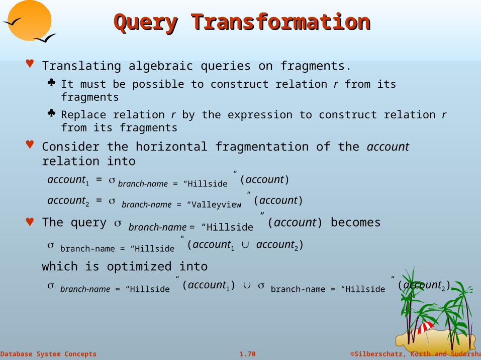
Query TransformationQuery Transformation
Translating algebraic queries on fragments. It must be possible to construct relation r from its fragments
Replace relation r by the expression to construct relation r from its fragments
Consider the horizontal fragmentation of the account relation into
account1 = branch-name = “Hillside” (account)
account2 = branch-name = “Valleyview” (account)
The query branch-name = “Hillside” (account) becomes
branch-name = “Hillside” (account1 account2)
which is optimized into
branch-name = “Hillside” (account1) branch-name = “Hillside” (account2)
71
©Silberschatz, Korth and Sudarshan1.71Database System Concepts
Example Query (cont.d)Example Query (cont.d)
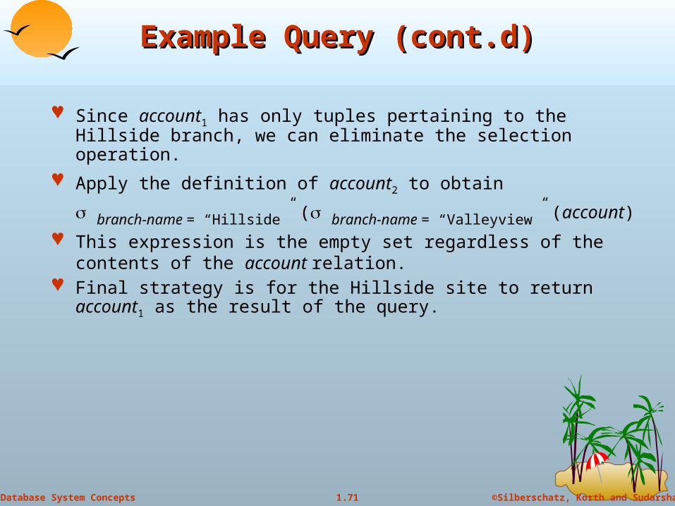
Since account1 has only tuples pertaining to the Hillside branch, we can eliminate the selection operation.
Apply the definition of account2 to obtain
branch-name = “Hillside” ( branch-name = “Valleyview” (account)
This expression is the empty set regardless of the contents of the account relation.
Final strategy is for the Hillside site to return account1 as the result of the query.

72
©Silberschatz, Korth and Sudarshan1.72Database System Concepts
Simple Join ProcessingSimple Join Processing
Consider the following relational algebra expression in which the three relations are neither replicated nor fragmented
account depositor branch
account is stored at site S1
depositor at S2
branch at S3
For a query issued at site SI, the system needs to produce the result at site SI

73
©Silberschatz, Korth and Sudarshan1.73Database System Concepts
Possible Query Processing StrategiesPossible Query Processing Strategies
Ship copies of all three relations to site SI and choose a strategy for processing the entire locally at site SI.
Ship a copy of the account relation to site S2 and compute temp1 = account depositor at S2. Ship temp1 from S2 to S3, and compute temp2 = temp1 branch at S3. Ship the result temp2 to SI.
Devise similar strategies, exchanging the roles S1, S2, S3
Must consider following factors: amount of data being shipped
cost of transmitting a data block between sites
relative processing speed at each site
74
©Silberschatz, Korth and Sudarshan1.74Database System Concepts
Semijoin StrategySemijoin Strategy
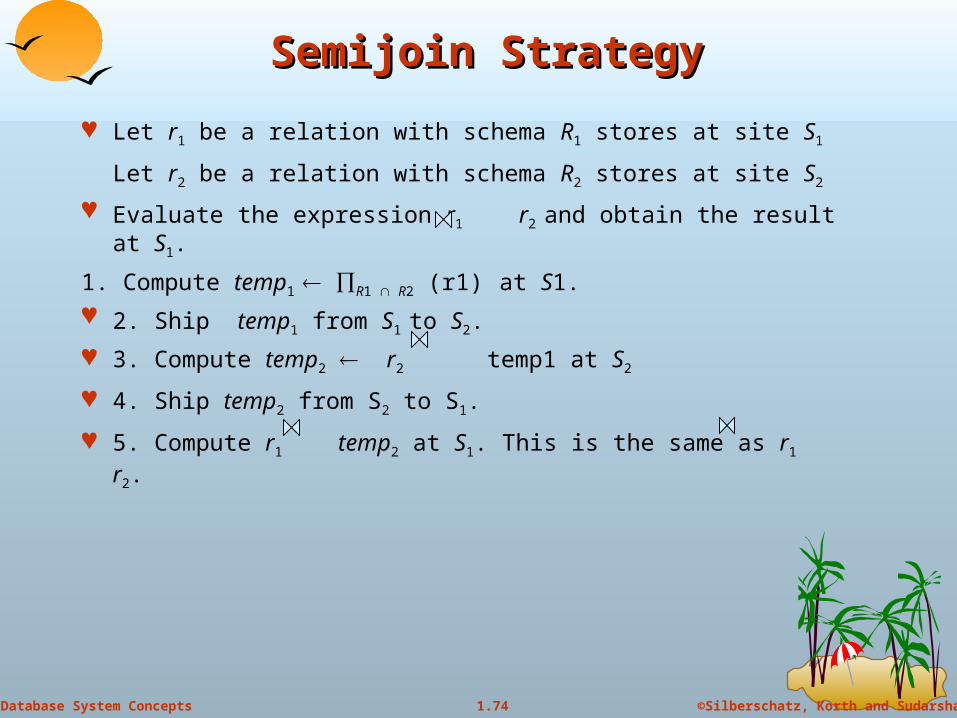
Let r1 be a relation with schema R1 stores at site S1
Let r2 be a relation with schema R2 stores at site S2
Evaluate the expression r1 r2 and obtain the result at S1.
1. Compute temp1 R1 R2 (r1) at S1.
2. Ship temp1 from S1 to S2.
3. Compute temp2 r2 temp1 at S2
4. Ship temp2 from S2 to S1.
5. Compute r1 temp2 at S1. This is the same as r1 r2.
75
©Silberschatz, Korth and Sudarshan1.75Database System Concepts
Formal DefinitionFormal Definition
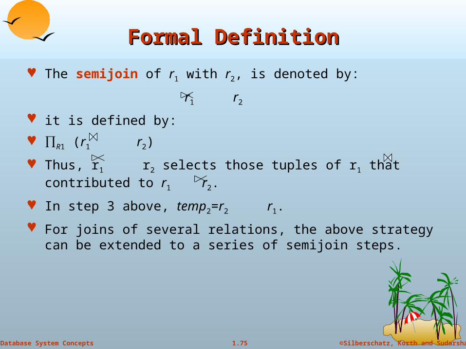
The semijoin of r1 with r2, is denoted by:
r1 r2
it is defined by:
R1 (r1 r2)
Thus, r1 r2 selects those tuples of r1 that contributed to r1 r2.
In step 3 above, temp2=r2 r1.
For joins of several relations, the above strategy can be extended to a series of semijoin steps.

76
©Silberschatz, Korth and Sudarshan1.76Database System Concepts
Join Strategies that Exploit ParallelismJoin Strategies that Exploit Parallelism
Consider r1 r2 r3 r4 where relation ri is stored at site Si. The
result must be presented at site S1.
r1 is shipped to S2 and r1 r2 is computed at S2: simultaneously r3 is
shipped to S4 and r3 r4 is computed at S4
S2 ships tuples of (r1 r2) to S1 as they produced;
S4 ships tuples of (r3 r4) to S1
Once tuples of (r1 r2) and (r3 r4) arrive at S1 (r1 r2) (r3 r4) is
computed in parallel with the computation of (r1 r2) at S2 and the
computation of (r3 r4) at S4.
77
©Silberschatz, Korth and Sudarshan1.77Database System Concepts
Heterogeneous Distributed DatabasesHeterogeneous Distributed Databases
Many database applications require data from a variety of preexisting databases located in a heterogeneous collection of hardware and software platforms
Data models may differ (hierarchical, relational , etc.)
Transaction commit protocols may be incompatible
Concurrency control may be based on different techniques (locking, timestamping, etc.)
System-level details almost certainly are totally incompatible.
A multidatabase system is a software layer on top of existing database systems, which is designed to manipulate information in heterogeneous databases Creates an illusion of logical database integration without any
physical database integration
78
©Silberschatz, Korth and Sudarshan1.78Database System Concepts
AdvantagesAdvantages
Preservation of investment in existing hardware
system software
Applications
Local autonomy and administrative control
Allows use of special-purpose DBMSs
Step towards a unified homogeneous DBMS Full integration into a homogeneous DBMS faces
Technical difficulties and cost of conversion
Organizational/political difficulties
Organizations do not want to give up control on their data
Local databases wish to retain a great deal of autonomy
79
©Silberschatz, Korth and Sudarshan1.79Database System Concepts
Unified View of DataUnified View of Data
Agreement on a common data model Typically the relational model
Agreement on a common conceptual schema Different names for same relation/attribute Same relation/attribute name means different things
Agreement on a single representation of shared data E.g. data types, precision, Character sets
ASCII vs EBCDIC Sort order variations
Agreement on units of measure Variations in names
E.g. Köln vs Cologne, Mumbai vs Bombay
80
©Silberschatz, Korth and Sudarshan1.80Database System Concepts
Query ProcessingQuery Processing
Several issues in query processing in a heterogeneous database
Schema translation Write a wrapper for each data source to translate data to a global
schema
Wrappers must also translate updates on global schema to updates on local schema
Limited query capabilities Some data sources allow only restricted forms of selections
E.g. web forms, flat file data sources
Queries have to be broken up and processed partly at the source and partly at a different site
Removal of duplicate information when sites have overlapping information Decide which sites to execute query
Global query optimization

81
©Silberschatz, Korth and Sudarshan1.81Database System Concepts
Mediator SystemsMediator Systems
Mediator systems are systems that integrate multiple heterogeneous data sources by providing an integrated global view, and providing query facilities on global view Unlike full fledged multidatabase systems, mediators generally do
not bother about transaction processing
But the terms mediator and multidatabase are sometimes used interchangeably
The term virtual database is also used to refer to mediator/multidatabase systems
Copyright: Silberschatz, Korth and Sudarhan
82
Distributed Directory SystemsDistributed Directory Systems
83
©Silberschatz, Korth and Sudarshan1.83Database System Concepts
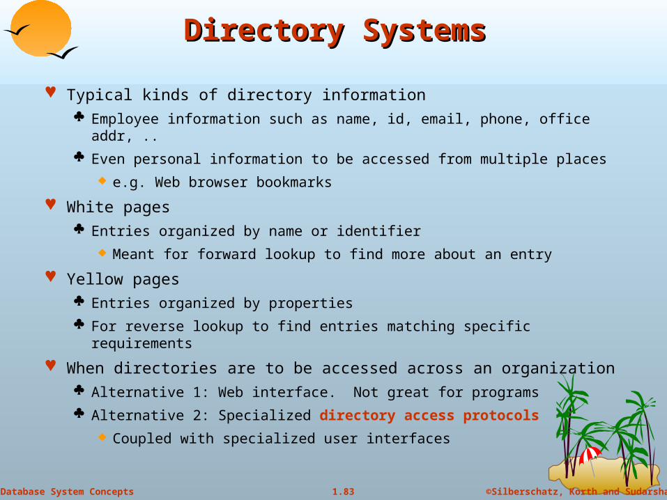
Directory SystemsDirectory Systems
Typical kinds of directory information Employee information such as name, id, email, phone, office addr, ..
Even personal information to be accessed from multiple places
e.g. Web browser bookmarks
White pages Entries organized by name or identifier
Meant for forward lookup to find more about an entry
Yellow pages Entries organized by properties
For reverse lookup to find entries matching specific requirements
When directories are to be accessed across an organization Alternative 1: Web interface. Not great for programs
Alternative 2: Specialized directory access protocols
Coupled with specialized user interfaces
84
©Silberschatz, Korth and Sudarshan1.84Database System Concepts
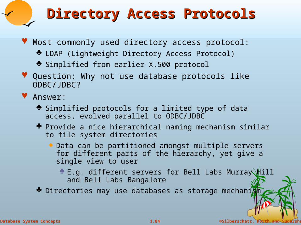
Directory Access ProtocolsDirectory Access Protocols
Most commonly used directory access protocol: LDAP (Lightweight Directory Access Protocol) Simplified from earlier X.500 protocol
Question: Why not use database protocols like ODBC/JDBC? Answer:
Simplified protocols for a limited type of data access, evolved parallel to ODBC/JDBC
Provide a nice hierarchical naming mechanism similar to file system directories Data can be partitioned amongst multiple servers for different
parts of the hierarchy, yet give a single view to user E.g. different servers for Bell Labs Murray Hill and Bell Labs
Bangalore Directories may use databases as storage mechanism

85
©Silberschatz, Korth and Sudarshan1.85Database System Concepts
LDAP:Lightweight Directory Access LDAP:Lightweight Directory Access ProtocolProtocol
LDAP Data Model
Data Manipulation
Distributed Directory Trees

86
©Silberschatz, Korth and Sudarshan1.86Database System Concepts
LDAP Data ModelLDAP Data Model
LDAP directories store entries Entries are similar to objects
Each entry must have unique distinguished name (DN)
DN made up of a sequence of relative distinguished names (RDNs)
E.g. of a DN cn=Silberschatz, ou-Bell Labs, o=Lucent, c=USA
Standard RDNs (can be specified as part of schema)
cn: common name ou: organizational unit
o: organization c: country
Similar to paths in a file system but written in reverse direction

87
©Silberschatz, Korth and Sudarshan1.87Database System Concepts
LDAP Data Model (cont.d)LDAP Data Model (cont.d)
Entries can have attributes Attributes are multi-valued by default
LDAP has several built-in types
Binary, string, time types
Tel: telephone number PostalAddress: postal address
LDAP allows definition of object classes Object classes specify attribute names and types
Can use inheritance to define object classes
Entry can be specified to be of one or more object classes
No need to have single most-specific type
88
©Silberschatz, Korth and Sudarshan1.88Database System Concepts
LDAP Data Model (cont.d)LDAP Data Model (cont.d)
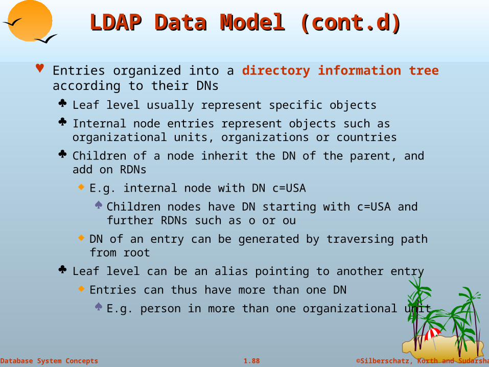
Entries organized into a directory information tree according to their DNs Leaf level usually represent specific objects
Internal node entries represent objects such as organizational units, organizations or countries
Children of a node inherit the DN of the parent, and add on RDNs
E.g. internal node with DN c=USA
Children nodes have DN starting with c=USA and further RDNs such as o or ou
DN of an entry can be generated by traversing path from root
Leaf level can be an alias pointing to another entry
Entries can thus have more than one DN
E.g. person in more than one organizational unit
89
©Silberschatz, Korth and Sudarshan1.89Database System Concepts
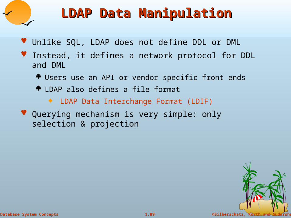
LDAP Data ManipulationLDAP Data Manipulation
Unlike SQL, LDAP does not define DDL or DML
Instead, it defines a network protocol for DDL and DML Users use an API or vendor specific front ends
LDAP also defines a file format
LDAP Data Interchange Format (LDIF)
Querying mechanism is very simple: only selection & projection

90
©Silberschatz, Korth and Sudarshan1.90Database System Concepts
LDAP QueriesLDAP Queries
LDAP query must specify Base: a node in the DIT from where search is to start
A search condition
Boolean combination of conditions on attributes of entries
Equality, wild-cards and approximate equality supported
A scope
Just the base, the base and its children, or the entire subtree from the base
Attributes to be returned
Limits on number of results and on resource consumption
May also specify whether to automatically dereference aliases
LDAP URLs are one way of specifying query
LDAP API is another alternative
91
©Silberschatz, Korth and Sudarshan1.91Database System Concepts
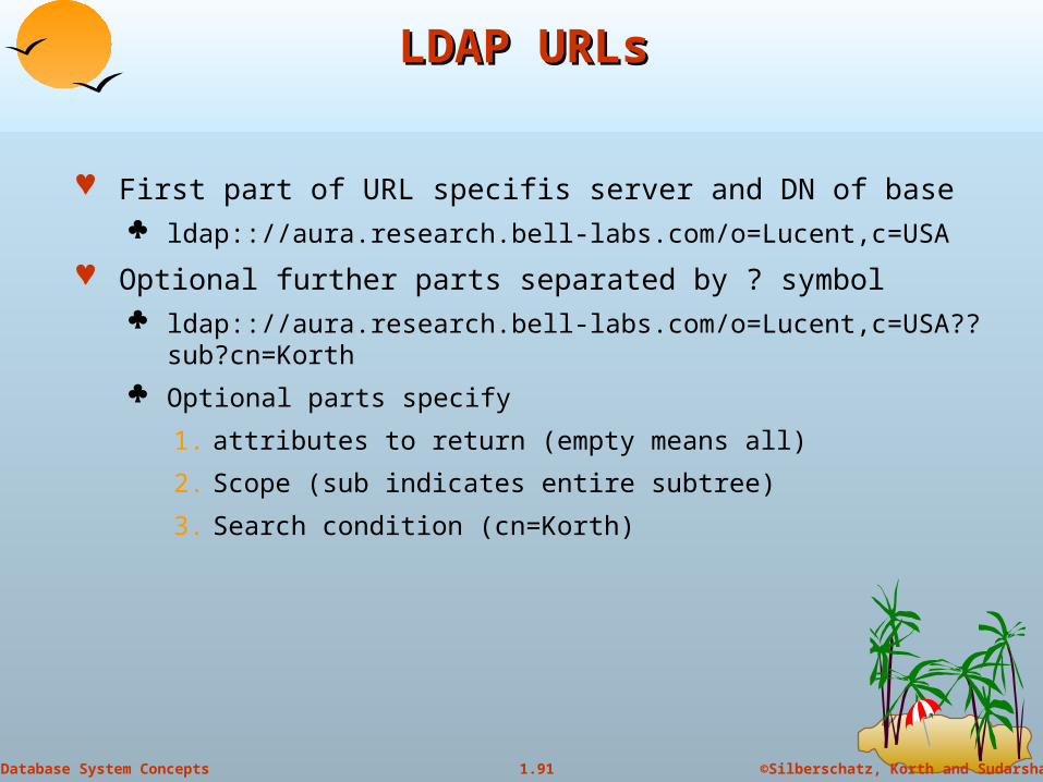
LDAP URLsLDAP URLs
First part of URL specifis server and DN of base ldap:://aura.research.bell-labs.com/o=Lucent,c=USA
Optional further parts separated by ? symbol ldap:://aura.research.bell-labs.com/o=Lucent,c=USA??sub?cn=Korth
Optional parts specify
1. attributes to return (empty means all)
2. Scope (sub indicates entire subtree)
3. Search condition (cn=Korth)

92
©Silberschatz, Korth and Sudarshan1.92Database System Concepts
C Code using LDAP APIC Code using LDAP API
#include <stdio.h>#include <ldap.h>main( ) {
LDAP *ld;LDAPMessage *res, *entry;char *dn, *attr, *attrList [ ] = {“telephoneNumber”,
NULL};BerElement *ptr;int vals, i; // Open a connection to serverld = ldap_open(“aura.research.bell-labs.com”, LDAP_PORT);ldap_simple_bind(ld, “avi”, “avi-passwd”);
… actual query (next slide) …
ldap_unbind(ld);}
93
©Silberschatz, Korth and Sudarshan1.93Database System Concepts
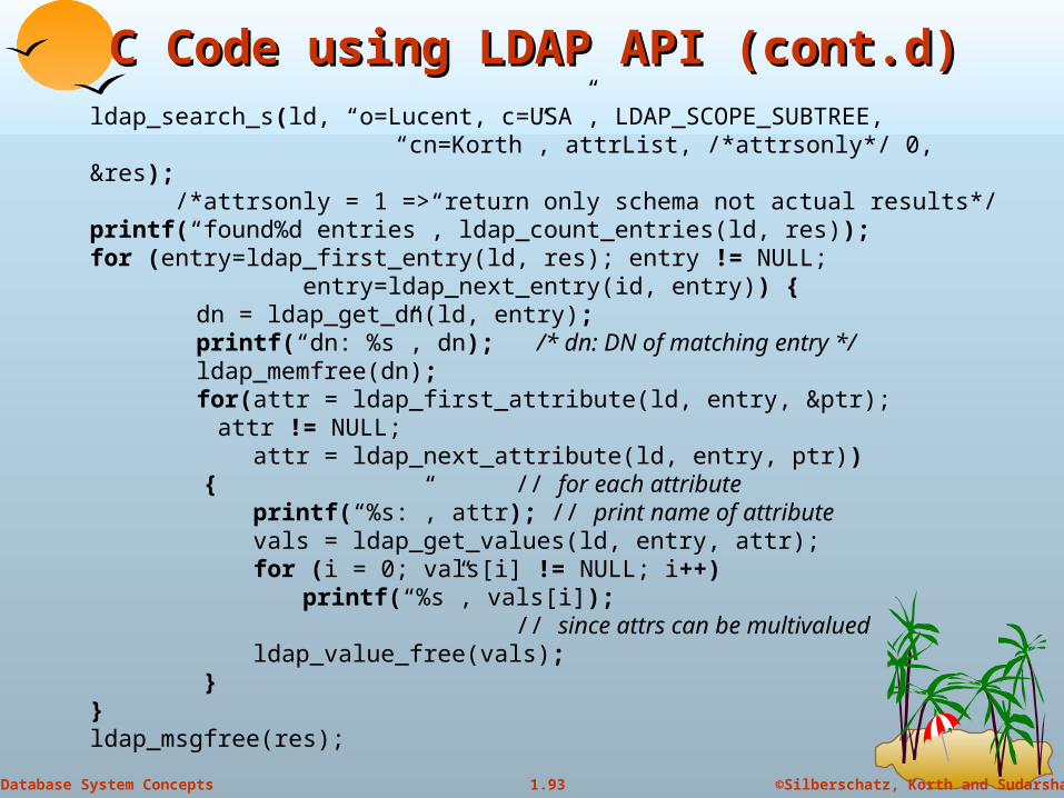
C Code using LDAP API (cont.d)C Code using LDAP API (cont.d)ldap_search_s(ld, “o=Lucent, c=USA”, LDAP_SCOPE_SUBTREE,
“cn=Korth”, attrList, /*attrsonly*/ 0, &res); /*attrsonly = 1 => return only schema not actual results*/ printf(“found%d entries”, ldap_count_entries(ld, res));for (entry=ldap_first_entry(ld, res); entry != NULL;
entry=ldap_next_entry(id, entry)) {dn = ldap_get_dn(ld, entry);printf(“dn: %s”, dn); /* dn: DN of matching entry */ldap_memfree(dn);for(attr = ldap_first_attribute(ld, entry, &ptr);
attr != NULL; attr = ldap_next_attribute(ld, entry, ptr))
{ // for each attribute printf(“%s:”, attr); // print name of attribute
vals = ldap_get_values(ld, entry, attr); for (i = 0; vals[i] != NULL; i++)
printf(“%s”, vals[i]); // since attrs can be multivalued
ldap_value_free(vals); }}ldap_msgfree(res);
94
©Silberschatz, Korth and Sudarshan1.94Database System Concepts
LDAP API (cont.d)LDAP API (cont.d)
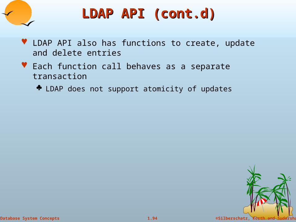
LDAP API also has functions to create, update and delete entries
Each function call behaves as a separate transaction LDAP does not support atomicity of updates

95
©Silberschatz, Korth and Sudarshan1.95Database System Concepts
Distributed Directory TreesDistributed Directory Trees
Organizational information may be split into multiple directory information trees Suffix of a DIT gives RDN to be tagged onto to all entries to get an overall DN
E.g. two DITs, one with suffix o=Lucent, c=USA and another with suffix o=Lucent, c=India
Organizations often split up DITs based on geographical location or by organizational structure
Many LDAP implementations support replication (master-slave or multi-master replication) of DITs (not part of LDAP 3 standard)
A node in a DIT may be a referral to a node in another DIT E.g. Ou= Bell Labs may have a separate DIT, and DIT for o=Lucent may have a
leaf with ou=Bell Labs containing a referral to the Bell Labs DIT
Referalls are the key to integrating a distributed collection of directories
When a server gets a query reaching a referral node, it may either
Forward query to referred DIT and return answer to client, or
Give referral back to client, which transparently sends query to referred DIT (without user intervention)
Copyright: Silberschatz, Korth and Sudarhan
96
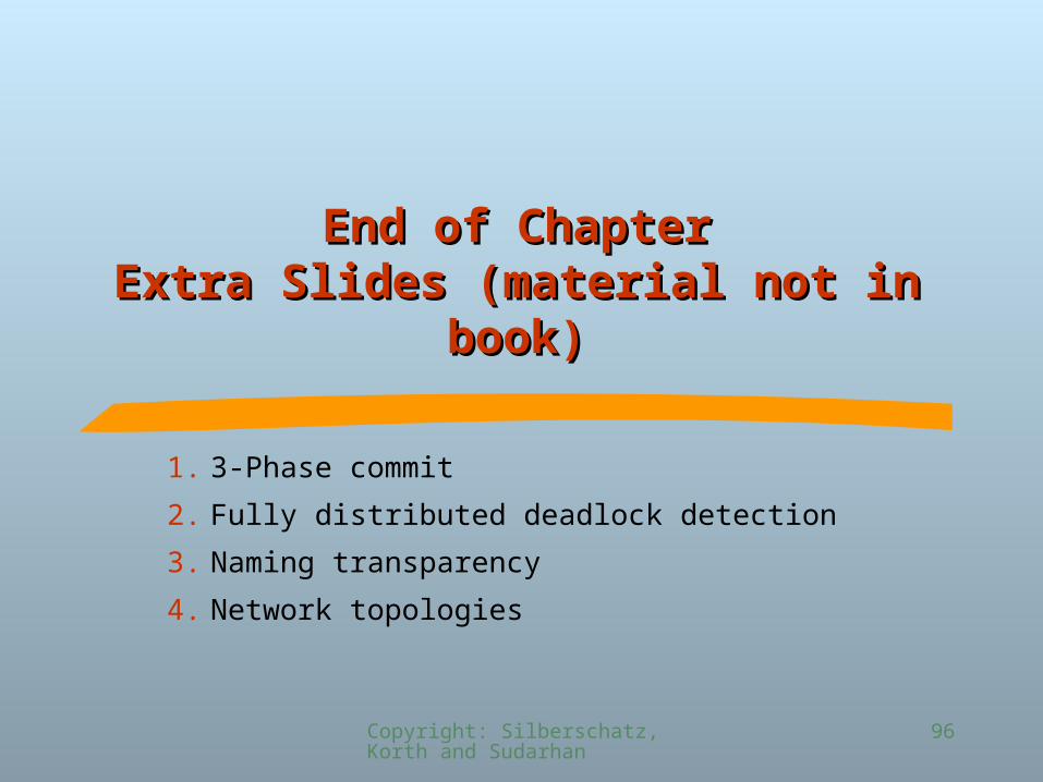
End of ChapterEnd of ChapterExtra Slides (material not in book)Extra Slides (material not in book)
1. 3-Phase commit
2. Fully distributed deadlock detection
3. Naming transparency
4. Network topologies
97
©Silberschatz, Korth and Sudarshan1.97Database System Concepts
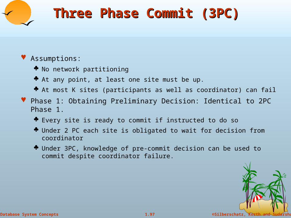
Three Phase Commit (3PC)Three Phase Commit (3PC)
Assumptions: No network partitioning
At any point, at least one site must be up.
At most K sites (participants as well as coordinator) can fail
Phase 1: Obtaining Preliminary Decision: Identical to 2PC Phase 1. Every site is ready to commit if instructed to do so
Under 2 PC each site is obligated to wait for decision from coordinator
Under 3PC, knowledge of pre-commit decision can be used to commit despite coordinator failure.
98
©Silberschatz, Korth and Sudarshan1.98Database System Concepts
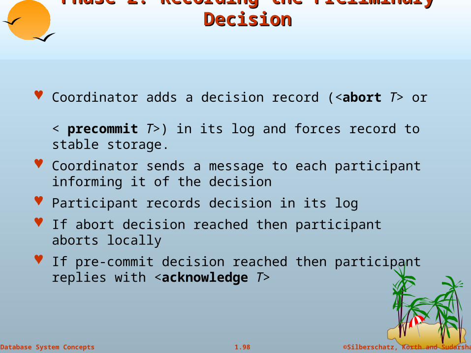
Phase 2. Recording the Preliminary DecisionPhase 2. Recording the Preliminary Decision
Coordinator adds a decision record (<abort T> or < precommit T>) in its log and forces record to stable storage.
Coordinator sends a message to each participant informing it of the decision
Participant records decision in its log
If abort decision reached then participant aborts locally
If pre-commit decision reached then participant replies with <acknowledge T>
99
©Silberschatz, Korth and Sudarshan1.99Database System Concepts
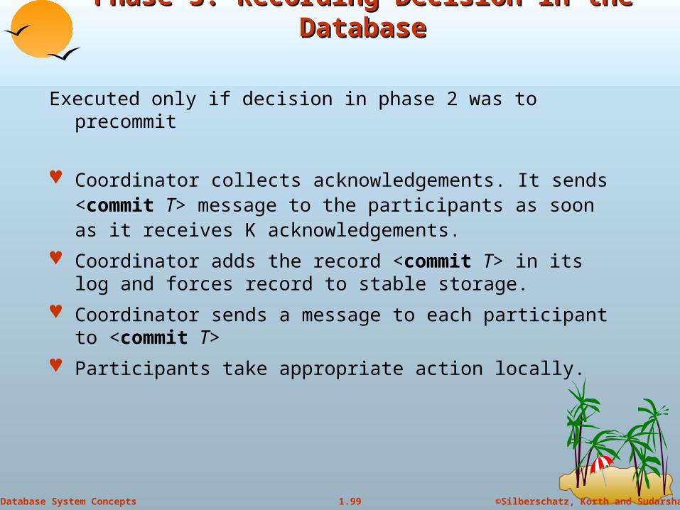
Phase 3. Recording Decision in the DatabasePhase 3. Recording Decision in the Database
Executed only if decision in phase 2 was to precommit
Coordinator collects acknowledgements. It sends <commit T> message to the participants as soon as it receives K acknowledgements.
Coordinator adds the record <commit T> in its log and forces record to stable storage.
Coordinator sends a message to each participant to <commit T>
Participants take appropriate action locally.
100
©Silberschatz, Korth and Sudarshan1.100Database System Concepts
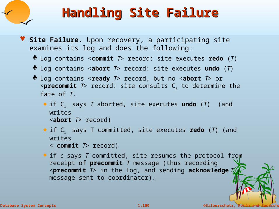
Handling Site FailureHandling Site Failure
Site Failure. Upon recovery, a participating site examines its log and does the following: Log contains <commit T> record: site executes redo (T)
Log contains <abort T> record: site executes undo (T)
Log contains <ready T> record, but no <abort T> or <precommit T> record: site consults Ci to determine the fate of T.
if Ci says T aborted, site executes undo (T) (and writes <abort T> record)
if Ci says T committed, site executes redo (T) (and writes < commit T> record)
if c says T committed, site resumes the protocol from receipt of precommit T message (thus recording <precommit T> in the log, and sending acknowledge T message sent to coordinator).
101
©Silberschatz, Korth and Sudarshan1.101Database System Concepts
Handling Site Failure (cont.d)Handling Site Failure (cont.d)
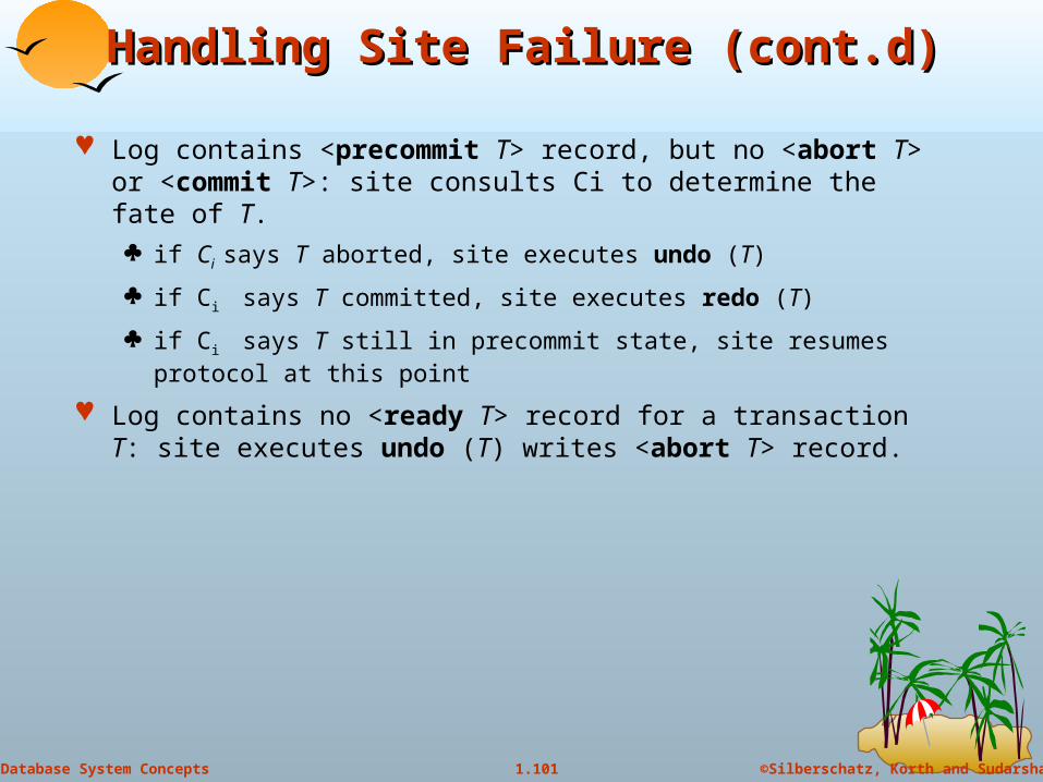
Log contains <precommit T> record, but no <abort T> or <commit T>: site consults Ci to determine the fate of T.
if Ci says T aborted, site executes undo (T)
if Ci says T committed, site executes redo (T)
if Ci says T still in precommit state, site resumes protocol at this point
Log contains no <ready T> record for a transaction T: site executes undo (T) writes <abort T> record.
102
©Silberschatz, Korth and Sudarshan1.102Database System Concepts
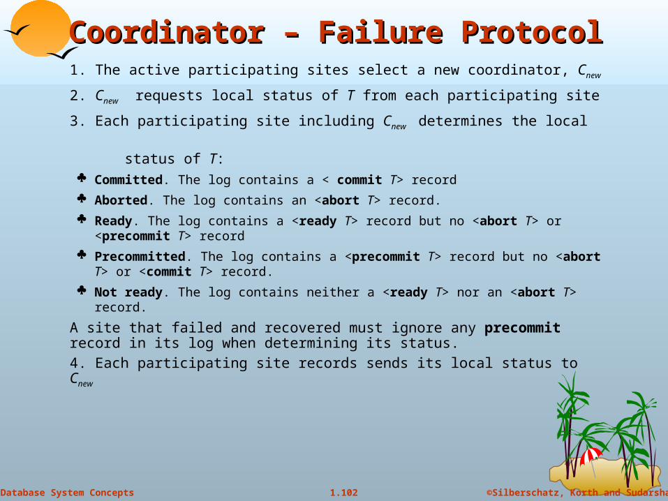
Coordinator – Failure ProtocolCoordinator – Failure Protocol1. The active participating sites select a new coordinator, Cnew
2. Cnew requests local status of T from each participating site
3. Each participating site including Cnew determines the local
status of T: Committed. The log contains a < commit T> record
Aborted. The log contains an <abort T> record.
Ready. The log contains a <ready T> record but no <abort T> or <precommit T> record
Precommitted. The log contains a <precommit T> record but no <abort T> or <commit T> record.
Not ready. The log contains neither a <ready T> nor an <abort T> record.
A site that failed and recovered must ignore any precommit record in its log when determining its status.
4. Each participating site records sends its local status to Cnew

103
©Silberschatz, Korth and Sudarshan1.103Database System Concepts
Coordinator Failure Protocol (cont.d)Coordinator Failure Protocol (cont.d)
5. Cnew decides either to commit or abort T, or to restart the
three-phase commit protocol: Commit state for any one participant commit
Abort state for any one participant abort.
Precommit state for any one participant and above 2 cases do not hold
A precommit message is sent to those participants in the uncertain state. Protocol is resumed from that point.
Uncertain state at all live participants abort. Since at least n - k sites are up, the fact that all participants are in an uncertain state means that the coordinator has not sent a <commit T> message implying that no site has committed T.
104
©Silberschatz, Korth and Sudarshan1.104Database System Concepts
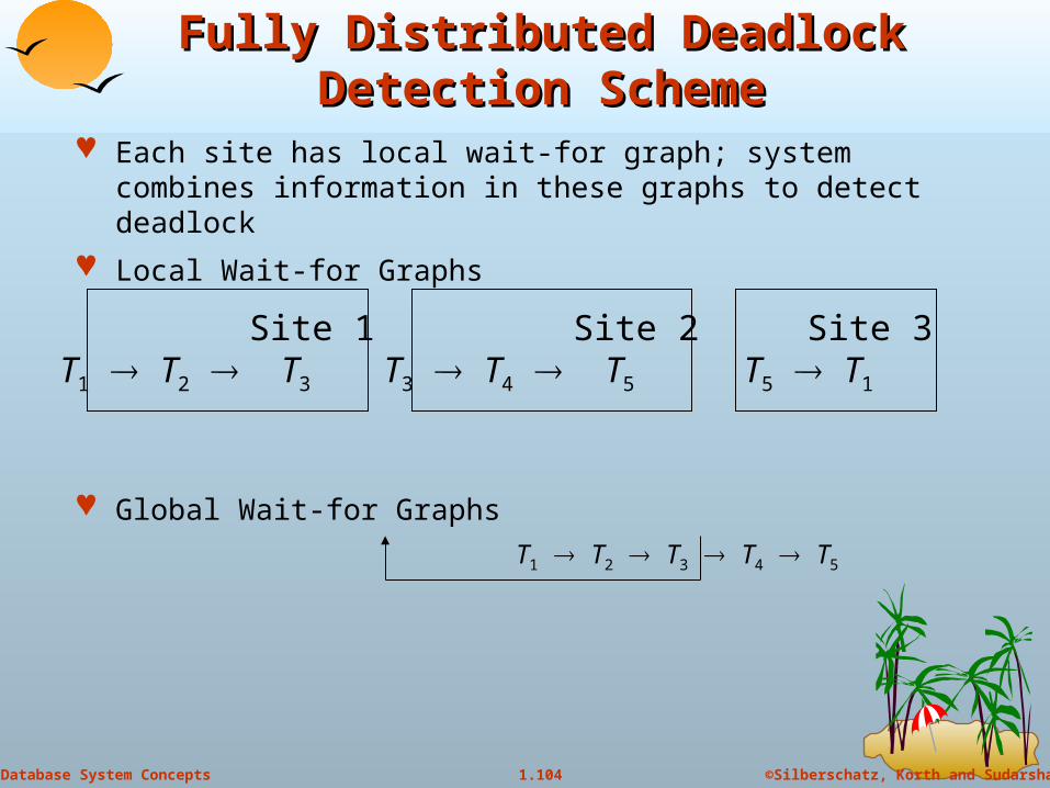
Fully Distributed Deadlock Detection Fully Distributed Deadlock Detection SchemeScheme
Each site has local wait-for graph; system combines information in these graphs to detect deadlock
Local Wait-for Graphs
Global Wait-for Graphs
T1 T2 T3 T4 T5
Site 1T1 T2 T3
Site 2T3 T4 T5
Site 3T5 T1

105
©Silberschatz, Korth and Sudarshan1.105Database System Concepts
Fully Distributed Approach (cont.d)Fully Distributed Approach (cont.d)
System model: a transaction runs at a single site, and makes requests to other sites for accessing non-local data.
Each site maintains its own local wait-for graph in the normal fashion: there is an edge Ti Tj if Ti is waiting on a lock held by Tj (note: Ti and Tj may be non-local).
Additionally, arc Ti Tex exists in the graph at site Sk if
(a) Ti is executing at site Sk, and is waiting for a reply to a request made on another site, or
(b) Ti is non-local to site Sk, and a lock has been granted to Ti at Sk.
Similarly arc Tex Ti exists in the graph at site Sk if
(a) Ti is non-local to site Sk, and is waiting on a lock for data at site Sk, or
(b) Ti is local to site Sk, and has accessed data from an external site.
106
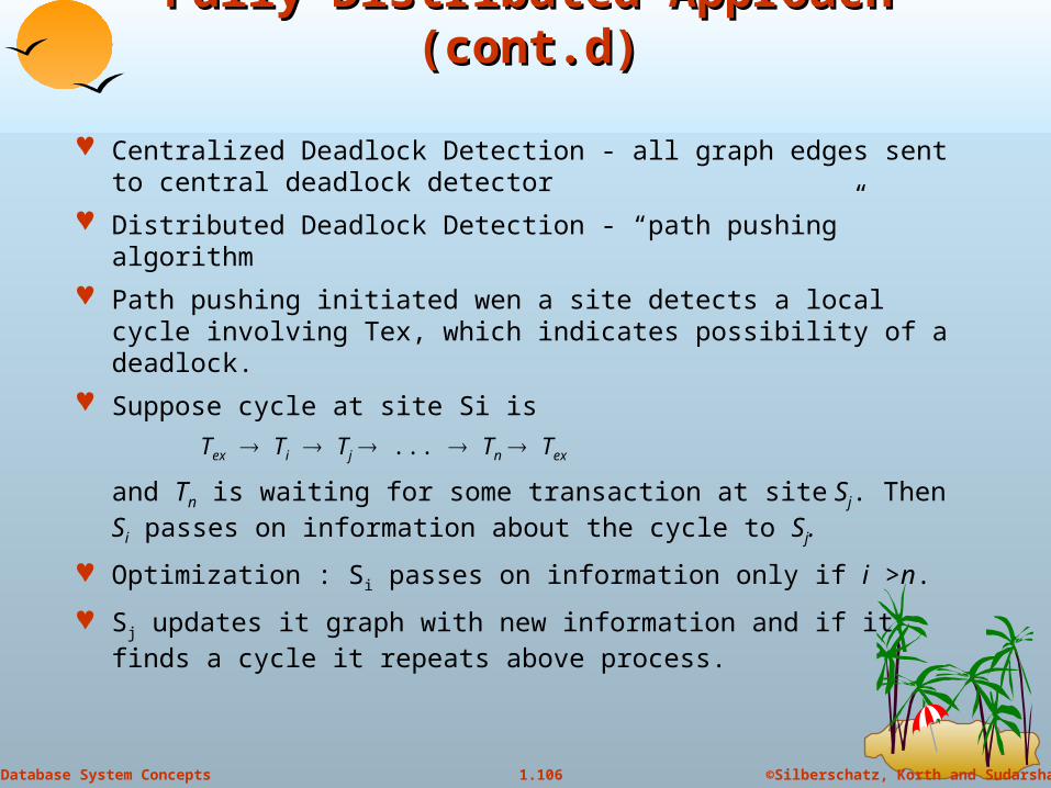
©Silberschatz, Korth and Sudarshan1.106Database System Concepts
Fully Distributed Approach (cont.d)Fully Distributed Approach (cont.d)
Centralized Deadlock Detection - all graph edges sent to central deadlock detector
Distributed Deadlock Detection - “path pushing” algorithm
Path pushing initiated wen a site detects a local cycle involving Tex, which indicates possibility of a deadlock.
Suppose cycle at site Si is
Tex Ti Tj ... Tn Tex
and Tn is waiting for some transaction at site Sj. Then Si passes on information about the cycle to Sj.
Optimization : Si passes on information only if i >n.
Sj updates it graph with new information and if it finds a cycle it repeats above process.

107
©Silberschatz, Korth and Sudarshan1.107Database System Concepts
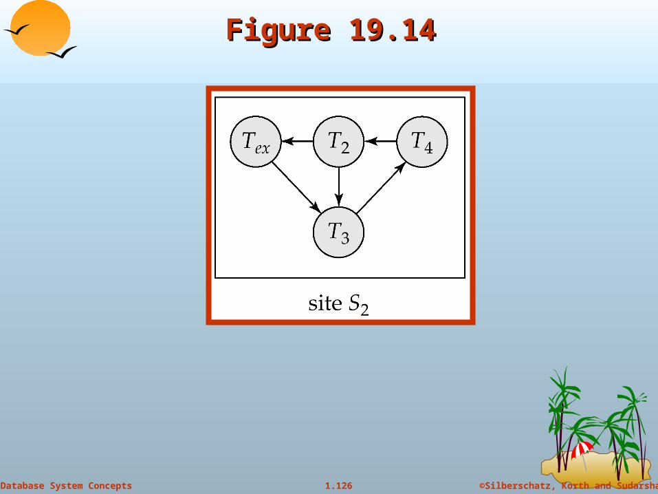
Fully Distributed Approach: ExampleFully Distributed Approach: Example
Site 1
EX(3) T1 T2 T3 EX(2)
Site 2
EX(1) T3 T4 T5 EX(3)
Site 3
EX(2) T5 T1 T3 EX(1)
EX (i): Indicates Tex, plus wait is on/by a transaction at Site i

108
©Silberschatz, Korth and Sudarshan1.108Database System Concepts
Fully Distributed Approach Example (cont.d)Fully Distributed Approach Example (cont.d)
Site passes wait-for information along path in graph:
Let EX(j) Ti ... Tn EX (k) be a path in local wait-for graph at Site m
Site m “pushes” the path information to site k if i > n
Example: Site 1 does not pass information : 1 > 3
Site 2 does not pass information : 3 > 5
Site 3 passes (T5, T1) to Site 1 because:
5 > 1
T1 is waiting for a data item at site 1
109
©Silberschatz, Korth and Sudarshan1.109Database System Concepts
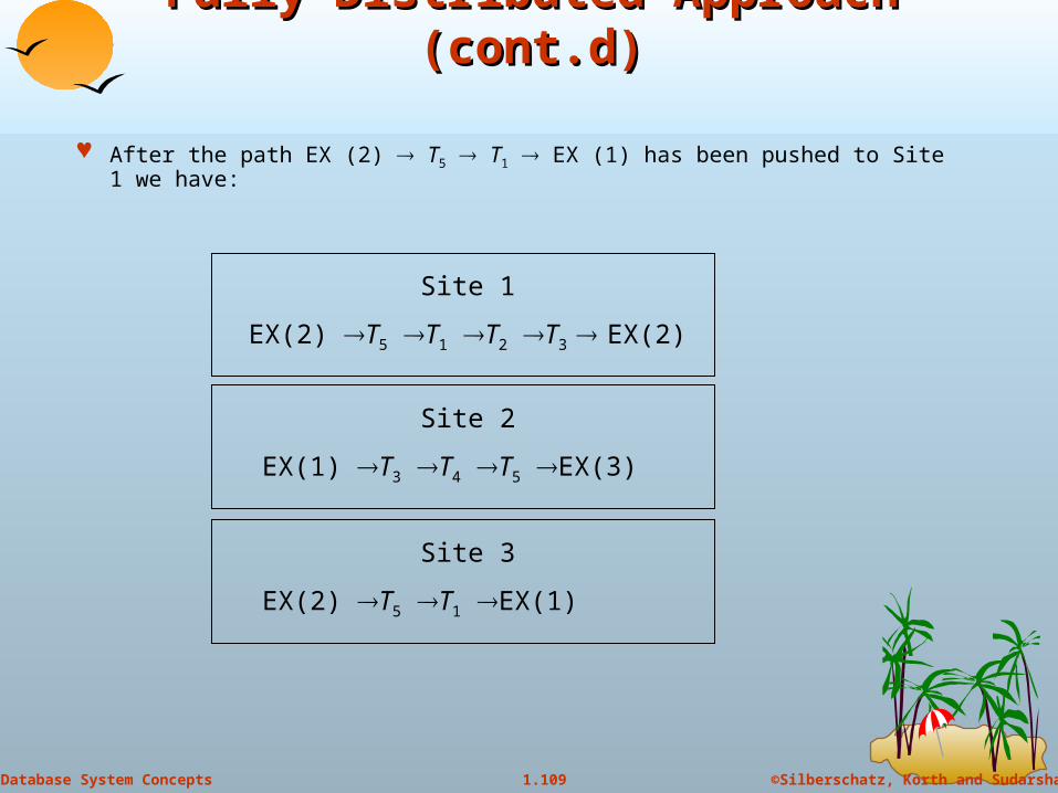
Fully Distributed Approach (cont.d)Fully Distributed Approach (cont.d)
After the path EX (2) T5 T1 EX (1) has been pushed to Site 1 we have:
Site 1
EX(2) T5 T1 T2 T3 EX(2)
Site 2
EX(1) T3 T4 T5 EX(3)
Site 3
EX(2) T5 T1 EX(1)
110
©Silberschatz, Korth and Sudarshan1.110Database System Concepts
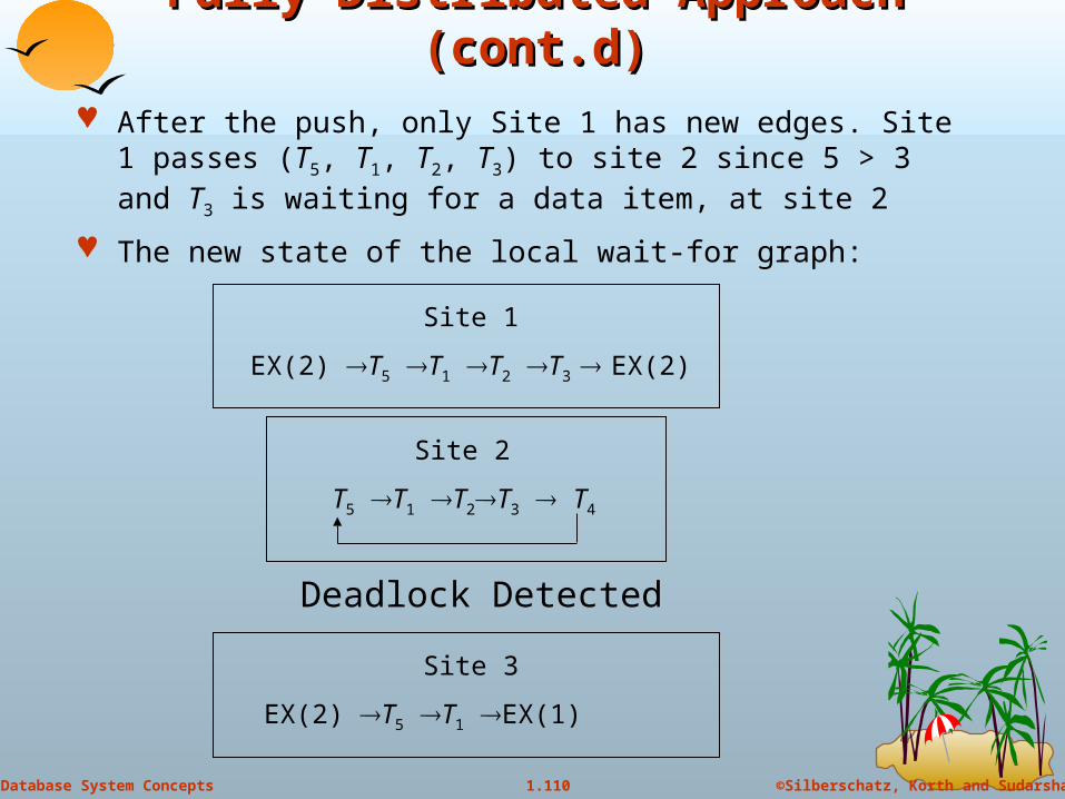
Fully Distributed Approach (cont.d)Fully Distributed Approach (cont.d)
After the push, only Site 1 has new edges. Site 1 passes (T5, T1, T2, T3) to site 2 since 5 > 3 and T3 is waiting for a data item, at site 2
The new state of the local wait-for graph:
Site 1
EX(2) T5 T1 T2 T3 EX(2)
Site 2
T5 T1 T2T3 T4
Site 3
EX(2) T5 T1 EX(1)
Deadlock Detected
Copyright: Silberschatz, Korth and Sudarhan
111
Naming of ItemsNaming of Items
112
©Silberschatz, Korth and Sudarshan1.112Database System Concepts
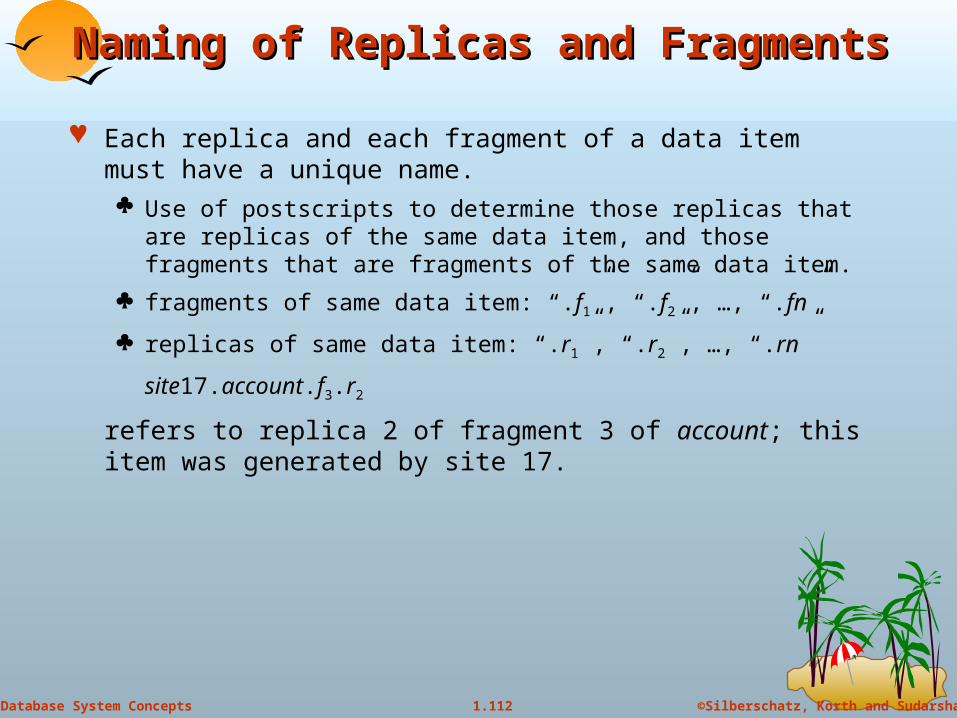
Naming of Replicas and FragmentsNaming of Replicas and Fragments
Each replica and each fragment of a data item must have a unique name. Use of postscripts to determine those replicas that are replicas of
the same data item, and those fragments that are fragments of the same data item.
fragments of same data item: “.f1”, “.f2”, …, “.fn”
replicas of same data item: “.r1”, “.r2”, …, “.rn”
site17.account.f3.r2
refers to replica 2 of fragment 3 of account; this item was generated by site 17.

113
©Silberschatz, Korth and Sudarshan1.113Database System Concepts
Name - Translation AlgorithmName - Translation Algorithmif name appears in the alias table
then expression := map (name)
else expression := name;
function map (n)
if n appears in the replica table
then result := name of replica of n;
if n appears in the fragment table
then begin
result := expression to construct fragment;
for each n’ in result do begin
replace n’ in result with map (n’);end
end
return result;
114
©Silberschatz, Korth and Sudarshan1.114Database System Concepts
Example of Name - Translation SchemeExample of Name - Translation Scheme
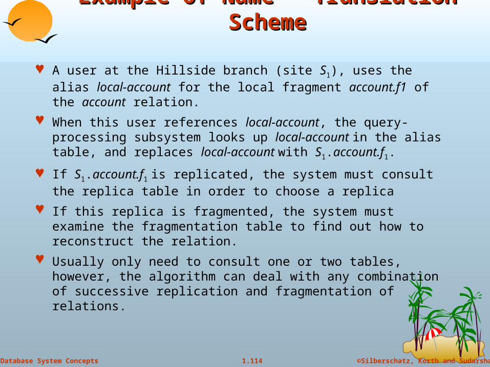
A user at the Hillside branch (site S1), uses the alias local-account for the local fragment account.f1 of the account relation.
When this user references local-account, the query-processing subsystem looks up local-account in the alias table, and replaces local-account with S1.account.f1.
If S1.account.f1 is replicated, the system must consult the replica table in order to choose a replica
If this replica is fragmented, the system must examine the fragmentation table to find out how to reconstruct the relation.
Usually only need to consult one or two tables, however, the algorithm can deal with any combination of successive replication and fragmentation of relations.
115
©Silberschatz, Korth and Sudarshan1.115Database System Concepts
Transparency and UpdatesTransparency and Updates
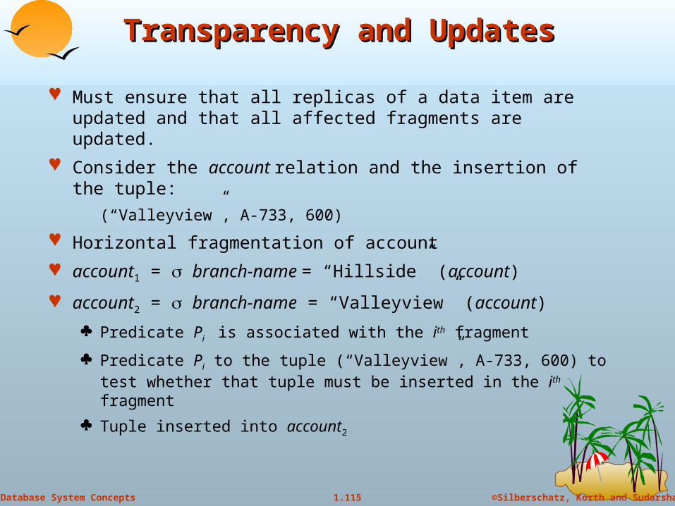
Must ensure that all replicas of a data item are updated and that all affected fragments are updated.
Consider the account relation and the insertion of the tuple:
(“Valleyview”, A-733, 600)
Horizontal fragmentation of account
account1 = branch-name = “Hillside” (account)
account2 = branch-name = “Valleyview” (account)
Predicate Pi is associated with the ith fragment
Predicate Pi to the tuple (“Valleyview”, A-733, 600) to test whether that tuple must be inserted in the ith fragment
Tuple inserted into account2
116
©Silberschatz, Korth and Sudarshan1.116Database System Concepts
Transparency and Updates (cont.d)Transparency and Updates (cont.d)
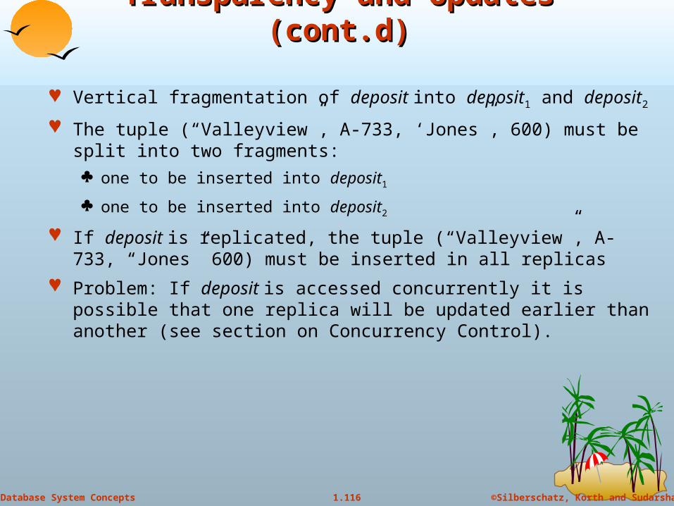
Vertical fragmentation of deposit into deposit1 and deposit2
The tuple (“Valleyview”, A-733, ‘Jones”, 600) must be split into two fragments:
one to be inserted into deposit1
one to be inserted into deposit2
If deposit is replicated, the tuple (“Valleyview”, A-733, “Jones” 600) must be inserted in all replicas
Problem: If deposit is accessed concurrently it is possible that one replica will be updated earlier than another (see section on Concurrency Control).
Copyright: Silberschatz, Korth and Sudarhan
117
Network TopologiesNetwork Topologies

118
©Silberschatz, Korth and Sudarshan1.118Database System Concepts
Network TopologiesNetwork Topologies
119
©Silberschatz, Korth and Sudarshan1.119Database System Concepts
Network Topologies (cont.d)Network Topologies (cont.d)
120
©Silberschatz, Korth and Sudarshan1.120Database System Concepts
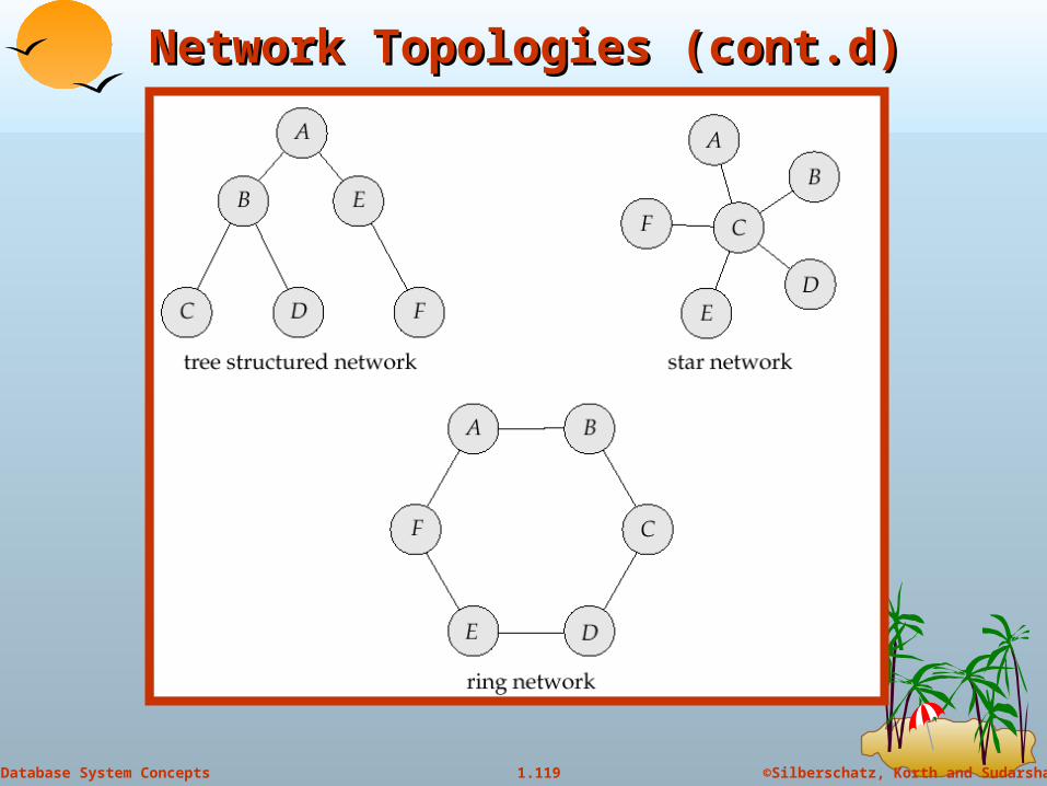
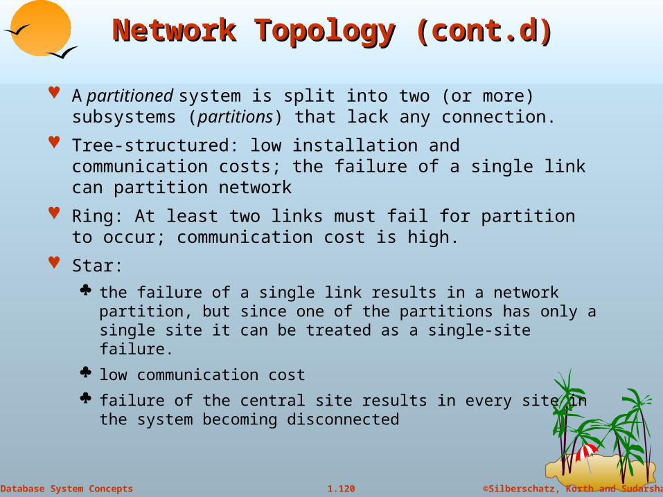
Network Topology (cont.d)Network Topology (cont.d)
A partitioned system is split into two (or more) subsystems (partitions) that lack any connection.
Tree-structured: low installation and communication costs; the failure of a single link can partition network
Ring: At least two links must fail for partition to occur; communication cost is high.
Star: the failure of a single link results in a network partition, but since one
of the partitions has only a single site it can be treated as a single-site failure.
low communication cost
failure of the central site results in every site in the system becoming disconnected
121
©Silberschatz, Korth and Sudarshan1.121Database System Concepts
RobustnessRobustness
A robustness system must: Detect site or link failures
Reconfigure the system so that computation may continue.
Recover when a processor or link is repaired
Handling failure types: Retransmit lost messages
Unacknowledged retransmits indicate link failure; find alternative route for message.
Failure to find alternative route is a symptom of network partition.
Network link failures and site failures are generally indistinguishable.

122
©Silberschatz, Korth and Sudarshan1.122Database System Concepts
Procedure to Reconfigure SystemProcedure to Reconfigure System
If replicated data is stored at the failed site, update the catalog so that queries do not reference the copy at the failed site.
Transactions active at the failed site should be aborted.
If the failed site is a central server for some subsystem, an election must be held to determine the new server.
Reconfiguration scheme must work correctly in case of network partitioning; must avoid: Electing two or more central servers in distinct partitions.
Updating replicated data item by more than one partition
Represent recovery tasks as a series of transactions; concurrent control subsystem and transactions management subsystem may then be relied upon for proper reintegration.

Copyright: Silberschatz, Korth and Sudarhan
123
End of ChapterEnd of Chapter
124
©Silberschatz, Korth and Sudarshan1.124Database System Concepts
Figure 19.7Figure 19.7

125
©Silberschatz, Korth and Sudarshan1.125Database System Concepts
Figure 19.13Figure 19.13
126
©Silberschatz, Korth and Sudarshan1.126Database System Concepts
Figure 19.14Figure 19.14
Top Related