


Languages
Pages
Legal

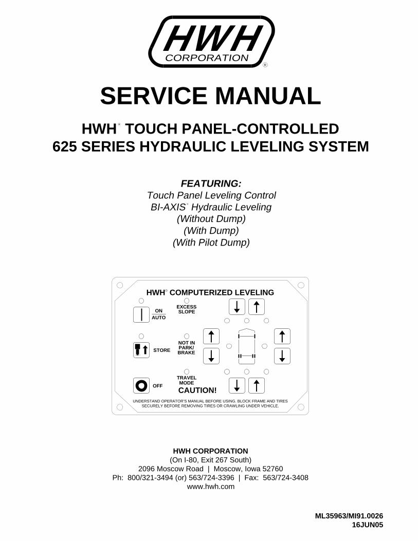
SERVICE MANUAL
ML35963/MI91.002616JUN05
Touch Panel Leveling ControlBI-AXIS Hydraulic Leveling
FEATURING:
HWH CORPORATION(On I-80, Exit 267 South)
2096 Moscow Road | Moscow, Iowa 52760Ph: 800/321-3494 (or) 563/724-3396 | Fax: 563/724-3408
www.hwh.com
625 SERIES HYDRAULIC LEVELING SYSTEMHWH TOUCH PANEL-CONTROLLED
R
(Without Dump)
R
HWH COMPUTERIZED LEVELING
UNDERSTAND OPERATOR’S MANUAL BEFORE USING. BLOCK FRAME AND TIRESSECURELY BEFORE REMOVING TIRES OR CRAWLING UNDER VEHICLE.
CAUTION!
EXCESS
STORE
AUTO
OFF
ON
TRAVELMODE
SLOPE
NOT IN
BRAKEPARK/
R
CORPORATIONWH H
R
(With Dump)(With Pilot Dump)
SECTION 1
MI91.113201NOV11
SECTION2
DIAGRAMS
SECTION
1
AND TROUBLE
SHOOTING
GUIDE
2 PART FOLDER
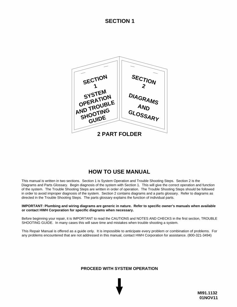
HOW TO USE MANUAL
Before beginning your repair, it is IMPORTANT to read the CAUTIONS and NOTES AND CHECKS in the first section, TROUBLESHOOTING GUIDE. In many cases this will save time and mistakes when trouble shooting a system.
This Repair Manual is offered as a guide only. It is impossible to anticipate every problem or combination of problems. Forany problems encountered that are not addressed in this manual, contact HWH Corporation for assistance. (800-321-3494)
PROCEED WITH SYSTEM OPERATION
ANDGLOSSARY
OPERATIONSYSTEM
This manual is written in two sections. Section 1 is System Operation and Trouble Shooting Steps. Section 2 is the Diagrams and Parts Glossary. Begin diagnosis of the system with Section 1. This will give the correct operation and function of the system. The Trouble Shooting Steps are written in order of operation. The Trouble Shooting Steps should be followed in order to avoid improper diagnosis of the system. Section 2 contains diagrams and a parts glossary. Refer to diagrams as directed in the Trouble Shooting Steps. The parts glossary explains the function of individual parts.
IMPORTANT: Plumbing and wiring diagrams are generic in nature. Refer to specific owner’s manuals when availableor contact HWH Corporation for specific diagrams when necessary.
TROUBLE SHOOTING
MI91.114225APR11
WARNING!
BLOCK FRAME AND TIRES SECURELY BEFORE CRAWLING UNDER VEHICLE. DO NOT USE THE LEVELINGJACKS OR AIR SUSPENSION TO SUPPORT VEHICLE WHILE UNDER VEHICLE OR CHANGING TIRES. VEHICLEMAY DROP AND OR MOVE FORWARD OR BACKWARD WITHOUT WARNING CAUSING INJURY OR DEATH.
WHEN ROUTING OR REROUTING HYDRAULIC HOSES AND WIRES, BE SURE THEY ARE NOT EXPOSED TO ENGINEEXHAUST OR ANY HIGH TEMPERATURE COMPONENTS OF THE VEHICLE.
NEVER PLACE HAND OR OTHER PARTS OF THE BODY NEAR HYDRAULIC LEAKS. OIL MAY CUT AND PENETRATE THE SKIN CAUSING INJURY OR DEATH.
SAFETY CLASSES ARE TO BE WORN TO PROTECT EYES FROM DIRT, METAL CHIPS, OIL LEAKS, ECT. FOLLOWALL OTHER SHOP SAFETY PRACTICES.
NOTES AND CHECKSRead and check before proceeding with Trouble Shooting Steps.
NOTE: HWH CORPORATION ASSUMES NO LIABILITYFOR DAMAGES OR INJURIES RESULTING FROM THEINSTALLATION OR REPAIR OF THIS PRODUCT.
1. If the jacks cannot be retracted, see TROUBLE SHOOTING PART 15 Step 2 for temporary measures. Make sure the manual retract valves are closed before trouble shooting.
2. The Trouble Shooting Guide must be followed in order. Problems checked for in one step are assumed correct and may not be checked again in following steps.
retracted position. If the vehicle is equipped with HWH room
4. Most coaches have more than one battery; one for the engineand the other(s) for the coach. The engine battery suppliespower for the control box and hydraulic pump. Batteries underno load should read 12.6 volts. Batteries must maintain good
6. Do not replace the control box unless the Repair Steps sayto replace it. Otherwise the malfunctions may damage thenew control box.
5. Proper grounding of all components is critical. See the electrical circuit for specific grounds required. Faulty grounds,especially for the control box, solenoid manifold or the pumpassembly, may cause control box component damage and /orimproper or erratic operation.
This manual is intended for use by experienced mechanicswith knowledge of hydraulic and automotive electricalsystems. People with little or no experience with HWHleveling systems should contact HWH technical service(800-321-3494) before beginning. Special attention shouldbe given to all cautions, wiring, and hydraulic diagrams.
Special note: When installing a new control box, makesure the box is properly grounded before applying powerto the system.
Suggested tools for trouble shooting the HWH leveling systems:JUMPER WIRES (UP TO 10 GAUGE)PRESSURE GAUGE (3500 PSI MIN.)MULTI-METER12 VOLT TEST LIGHT
PROCEED WITH THE TROUBLESHOOTING STEPS ON THE
FOLLOWING PAGE
3. Check that the oil reservoir is full with the jacks in the fully
voltage under load. Batteries must be in good condition withno weak cells. An alternator, converter or battery charger willnot supply enough power for the system to operate properly.
existing hose end, tighten the hose end to snug plus 1/4tighten the hose end 1/3 turn (2 FLATS). If tightening anmake the hose end snug (finger tight) on the fitting, thenTightening of hose ends: If tightening a new hose end,
turn (1 FLAT).
extensions, refer to the HWH Owners Manual for properposition of the room when checking the oil level.
MI91.115222MAY07
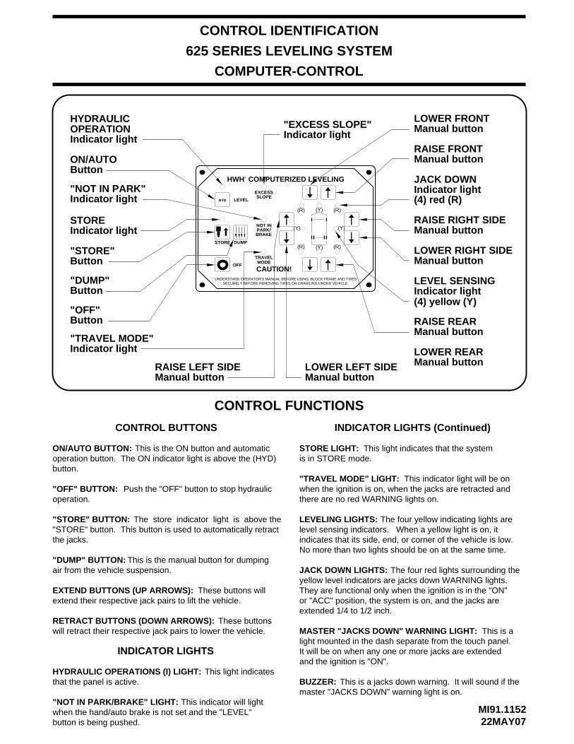
"OFF" BUTTON:operation.
ON/AUTO BUTTON:
"STORE" BUTTON:"STORE" button. This button is used to automatically retractthe jacks.
JACK DOWN LIGHTS:
"NOT IN PARK/BRAKE" LIGHT:when the hand/auto brake is not set and the "LEVEL"
"TRAVEL MODE" LIGHT:when the ignition is on, when the jacks are retracted and there are no red WARNING lights on.
MASTER "JACKS DOWN" WARNING LIGHT:light mounted in the dash separate from the touch panel.
and the ignition is "ON".
BUZZER:
CONTROL FUNCTIONS
INDICATOR LIGHTS
CONTROL BUTTONS
Push the "OFF" button to stop hydraulic
The store indicator light is above the
This indicator will light
This indicator light will be on
This is a
This is a jacks down warning. It will sound if the
EXTEND BUTTONS (UP ARROWS):
RETRACT BUTTONS (DOWN ARROWS):
LEVELING LIGHTS:
These buttons will extend their respective jack pairs to lift the vehicle.
These buttonswill retract their respective jack pairs to lower the vehicle.
The four yellow indicating lights are level sensing indicators. When a yellow light is on, it indicates that its side, end, or corner of the vehicle is low. No more than two lights should be on at the same time.
This is the ON button and automatic
The four red lights surrounding the yellow level indicators are jacks down WARNING lights. They are functional only when the ignition is in the "ON"
extended 1/4 to 1/2 inch.
operation button. The ON indicator light is above the (HYD)
master "JACKS DOWN" warning light is on.
CONTROL IDENTIFICATION
625 SERIES LEVELING SYSTEM
COMPUTER-CONTROL
or "ACC" position, the system is on, and the jacks are
It will be on when any one or more jacks are extended
button.
button is being pushed.
INDICATOR LIGHTS (Continued)
HYDRAULIC OPERATIONS (I) LIGHT:
HWH COMPUTERIZED LEVELING
UNDERSTAND OPERATOR’S MANUAL BEFORE USING. BLOCK FRAME AND TIRESSECURELY BEFORE REMOVING TIRES OR CRAWLING UNDER VEHICLE.
CAUTION!
HYDRAULIC
Indicator lightSTORE
Indicator light"TRAVEL MODE"
ON/AUTO
Indicator light OPERATION
Indicator light"NOT IN PARK"
Button"OFF"
Button"STORE"
Button
Manual buttonLOWER LEFT SIDE
Manual buttonRAISE LEFT SIDE
Indicator light"EXCESS SLOPE"
EXCESS
OFF
TRAVELMODE
SLOPE
NOT IN
BRAKEPARK/
R
Manual buttonLOWER REAR
Manual buttonRAISE REAR
Indicator light LEVEL SENSING
Manual buttonLOWER RIGHT SIDE
Manual buttonRAISE RIGHT SIDE
Indicator lightJACK DOWN
Manual buttonRAISE FRONT
Manual buttonLOWER FRONT
This light indicatesthat the panel is active.
STORE LIGHT: This light indicates that the systemis in STORE mode.
(4) red (R)
(4) yellow (Y)
(R)(Y)(R)
(Y)
(R) (Y) (R)
(Y)
DUMPSTORE
LEVELHYD
"DUMP"Button
"DUMP" BUTTON: This is the manual button for dumpingair from the vehicle suspension.

MI91.116224NOV15
SYSTEM OPERATION
The 625 leveling system is a computer controlled, BI-AXIS push button system. This system has automatic or optional manualcontrol. This system will always extend two (2) jacks at the same time in the automatic or manual mode, both front jacks, theleft front and left rear jacks, the right front and right rear jacks or both rear jacks. In the manual mode, the jacks are controlledby the UP and DOWN arrow buttons on the right hand side of the touch panel. The UP arrows extend jack pairs and the DOWNarrows retract jack pairs.
If the vehicle is equipped with an air suspension, the air must be exhausted from the suspension before leveling the vehicle. Ifthe air is not exhausted, the suspension height control valves will interfere with the leveling procedure. There are two types ofair dump systems that HWH controls. One system uses air solenoid valves supplied by HWH. The second system is suppliedby the chassis manufacturer. This is a pilot air dump system. In the automatic mode, the air is dumped automatically beforethe leveling process is started. For manual leveling, the HWH touch panel has a "DUMP" button. The "DUMP" button will onlywork if the POWER ON light is on. If the vehicle uses the HWH air dump valves, the "DUMP" button must be pushed and helduntil all of the air is exhausted from the vehicle suspension system. The engine must be off. If a pilot air dump system is used,the engine may be on or off. The "DUMP" button can be pushed and released. The pilot air dump system will return to the travel position if the ignition is on and the "STORE" button is pushed or the park brake is released.
AUTOMATIC OPERATIONThe ignition must be in the "ON" or "ACC." position and the park brake must be set to turn the system on. The "NOT IN PARK/BRAKE" indicator light will come on while the "ON" button is being pushed if the park brake signal is not present. The systemwill not turn on.
Pushing the "ON" (I) button will turn the system on. The POWER ON light should be lit and the DUMP button (if so equipped)
Push the "ON" (I) button a second time. The POWER ON light will flash. If applicable, the air will dump for thirty(30) seconds
On the right hand side of the touch panel there are four (4) red and four (4) yellow indicator lights. The four red indicator lightsare JACK DOWN warning lights. There is one light for each jack. These warning lights come on when their respective jacks are extended about 1/4 to 1/2 inch. The four yellow indicator lights are level indicators, front, left side, right side and rear. A lityellow level light indicates that a side, end or corner is low. When all four yellow level lights are out, the vehicle is level withinthe tolerance of the level sensing unit.
The computer will extend jack pairs according to the level lights starting with a lit side light. When all four level lights are out,the computer will extend any jacks not used for leveling to stabilize the vehicle. The computer looks for a jack pressure switchfrom each jack to know all jacks are on the ground. NOTE: Both front solenoid valves will come on during the stabilizeprocedure when either front jack pressure switch is not on. When both front jack pressure switches are on, both frontsolenoid valves will be off.
EXCESS SLOPE: Excess slope is when one or two jacks extend as far as they can without turning a yellow level light out.The pump will go to relief and trip a 3000# pressure switch on the leveling manifold. The "EXCESS SLOPE" light will come on.Jacks that have not been extended will not extend when the "EXCESS SLOPE" light is on. The "EXCESS SLOPE" light will beon whenever the ignition is on until the park brake is released (with the ignition on) or the jacks are completely retracted with the
The "OFF" button will turn the system off at any time.
"STORE" button.
There are two parts to leveling a vehicle. First the vehicle is leveled. The jacks are used to turn all the yellow level indicatorsoff. The second part of leveling is to stabilize the vehicle. This is accomplished by extending any jacks not used for leveling tothe ground and lifting the vehicle between 1/4 and 3/4 inch.
NOTE: Releasing the park brake to return the suspension to travel mode (vehicle to ride height) is not recommendedfor normal operation. This is a fail safe if the "STORE" button is not used to retract the jacks.
will function.
before the leveling procedure starts.
The master relay will be on any time the ignition is on. The park brake does not have to be set.
MI91.117203AUG09
625 TROUBLE SHOOTING GUIDE
On the right hand side of the touch panel there are four (4) red and four (4) yellow indicator lights. The four red indicator lightsare JACK DOWN warning lights. There is one light for each jack. These warning lights come on when their respective jacksare extended about 1/4 to 1/2 inch. The four yellow indicator lights are level indicators, front, left side, right side and rear. A lityellow level light indicates that a side, end or corner is low. When all four yellow level lights are out, the vehicle is level withinthe tolerance of the level sensing unit.
Use the UP ARROW (Extend jack pairs) and DOWN ARROW (Retract jack pairs) buttons to extend jack pairs asneeded to level and stabilize the vehicle. Side level lights should be turned off before turning off front or rear level lights.
The "OFF" button will turn the system off at any time.
STORE MODEThe touch panel has a "STORE" button and light. The "STORE" button will work with the POWER ON light on or off.The ignition must be in the "ON" or "ACC." position. The STORE light will come on when the "STORE" button is pushed. TheSTORE light will go out six (6) minutes after the last of the four individual red WARNING lights go out. If the POWER ON lightis on while the STORE light is on, the POWER ON light will go out at this time also. Vehicles equipped with a pilot air dump
The "STORE" button should always be used to retract the jacks. This allows the system to store any jack that extends due to
The ignition must be in the "ON" or "ACC." position and the park brake must be set to turn the system on. The "NOT IN PARK/BRAKE" indicator light will come on while the "ON" button is being pushed if the park brake signal is not present. The system
Pushing the "ON" (I) button will turn the system on. The POWER ON light should be lit. With the POWER ON light on, the UP
MANUAL OPERATION
or DOWN arrows and the DUMP button will function.
Use the DUMP button to dump the air before extending jacks.
will not turn on.
thermal expansion of the hydraulic fluid while traveling. When traveling, if a jack extends enough to allow a jack warning switchto turn on, the processor will turn the appropriate solenoid valve on so the jack can retract. The master warning light and buzzerwill NOT come on at this time. If thirty (30) seconds after the solenoid valve is turned on the warning switch is still on, theprocessor will turn the master warning light, the buzzer and the appropriate red WARNING light on the touch panel on.
IMPORTANT: When testing a leveling system, all four sets of UP and DOWN arrow buttons should be used to makesure the complete system operates correctly, including the red WARNING lights and the yellow LEVEL lights. If thesystem will not work in the manual mode it is very unlikely the system will function properly in the automatic mode.
system should return to ride height when the "STORE" button is pushed.
MI91.118215MAY08
625 TROUBLE SHOOTING STEPS
MANUAL OPERATION
NOTE: The following diagnostic functions are written in order of operation and should be checked in this order.Failure to do so may cause improper diagnoses of the problem(s) and increase the time needed to repair the system.
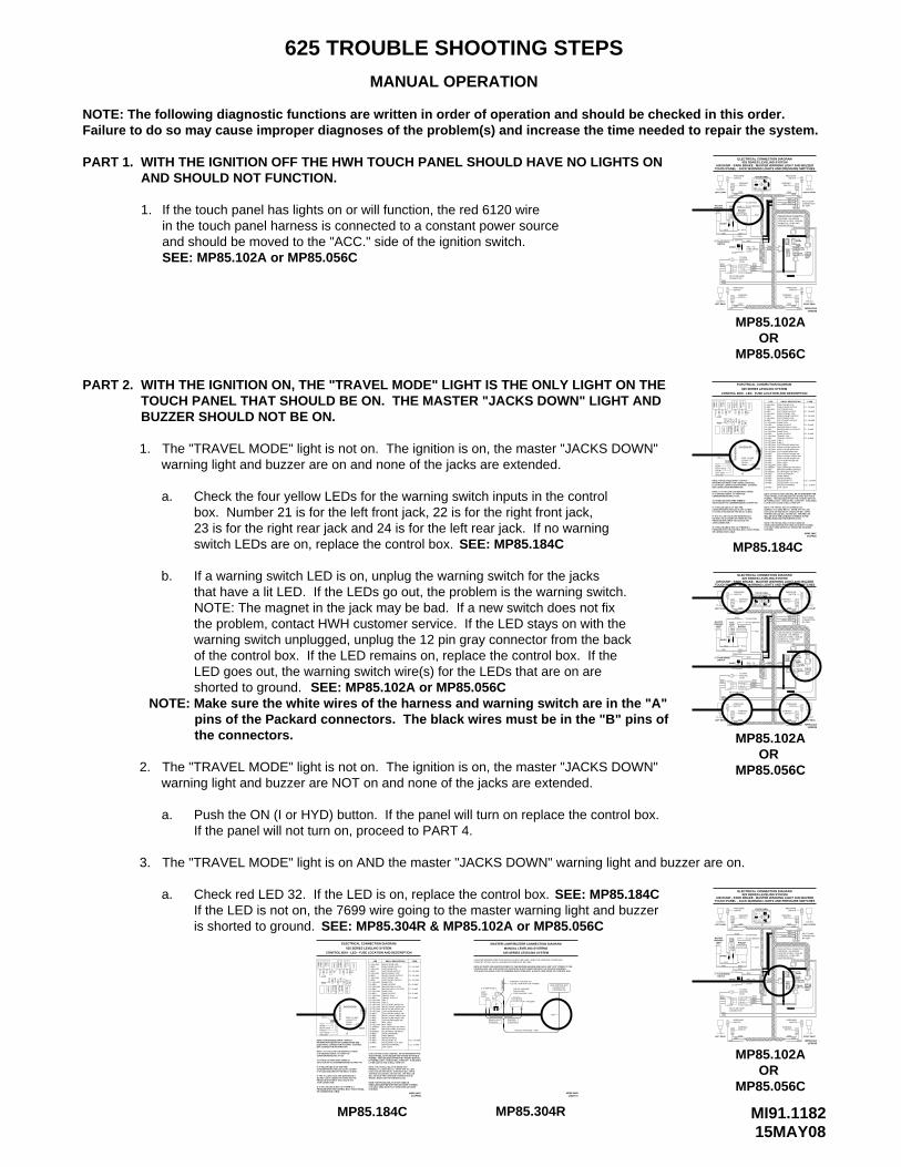
PART 1. WITH THE IGNITION OFF THE HWH TOUCH PANEL SHOULD HAVE NO LIGHTS ON AND SHOULD NOT FUNCTION.
1.in the touch panel harness is connected to a constant power source
PART 2.TOUCH PANEL THAT SHOULD BE ON. THE MASTER "JACKS DOWN" LIGHT AND
1.warning light and buzzer are on and none of the jacks are extended.
a.
b.
NOTE: The magnet in the jack may be bad. If a new switch does not fix the problem, contact HWH customer service. If the LED stays on with the warning switch unplugged, unplug the 12 pin gray connector from the back
Check the four yellow LEDs for the warning switch inputs in the control box. Number 21 is for the left front jack, 22 is for the right front jack,23 is for the right rear jack and 24 is for the left rear jack. If no warning
If a warning switch LED is on, unplug the warning switch for the jacks that have a lit LED. If the LEDs go out, the problem is the warning switch.
If the touch panel has lights on or will function, the red 6120 wire
The "TRAVEL MODE" light is not on. The ignition is on, the master "JACKS DOWN"
The "TRAVEL MODE" light is not on. The ignition is on, the master "JACKS DOWN"warning light and buzzer are NOT on and none of the jacks are extended.
2.
Push the ON (I or HYD) button. If the panel will turn on replace the control box. a.If the panel will not turn on, proceed to PART 4.
The "TRAVEL MODE" light is on AND the master "JACKS DOWN" warning light and buzzer are on.3.
a. Check red LED 32. If the LED is on, replace the control box. If the LED is not on, the 7699 wire going to the master warning light and buzzer
and should be moved to the "ACC." side of the ignition switch.SEE: MP85.102A or MP85.056C
LATER LED’S 3 AND 19 WILL TURN OFF.IS PUSHED, LED’s 7 AND 20 WILL TURN OFF. 5 SECONDSPUSHED. TWO SECONDS AFTER THE "STORE" BUTTONTOUCH PANEL IS ON UNLESS THE "STORE" BUTTON ISLED’S 19 AND 20 (YELLOW) WILL BE ON WHENEVER THE
SYSTEMS.IT IS ONLY USED WITH PILOT OPERATED AIR DUMPVEHICLES EQUIPPED WITH HWH AIR DUMP SYSTEMS.NOTE: THE TRAVEL RELAY IS NOT USED ON
TRAVEL MODE AND THE IGNITION IS ON.WILL BE ON IF THE LEVELING SYSTEM IS IN THE
NOTE: THE TRAVEL RELAY IS WIRED AS A NORMALLY CLOSED RELAY. WHEN THE YELLOWLED (17) IS ON THE RELAY CONTACTS WILL OPEN.THE RED LED (18) WILL NOT BE ON. THE RED LED
CONTROL BOX - LED - FUSE LOCATION AND DESCRIPTION
625 SERIES LEVELING SYSTEM
ELECTRICAL CONNECTION DIAGRAM
OR CONNECTION CABLEPROBLEM WITH THE CONTROL BOX, TOUCH PANEL
NOTE: A LIT YELLOW LED INDICATES THEREIS A GROUND SIGNAL TO TURN THE CORRESPONDING RELAY ON.
A LIT RED LED INDICATES THERE IS VOLTAGE ON IT’S CORRESPONDING OUTPUT PIN.
CORRESPONDING RED LED IS OFF, EITHERIT’S FUSE IS BLOWN OR THE RELAY IS BAD.
IF THE YELLOW LED’S ARE WORKING BUTNO RED LED IS COMING ON THERE MAY BEPROBLEM WITH INPUT VOLTAGE IN THE 4-PIN CONNECTOR.
IF A YELLOW LED IS NOT LIT, THERE IS A
IF A YELLOW LED IS LIT AND THE
BOX CONNECTION INFORMATION.ELECTRICAL CONNECTION DIAGRAM - CONTROLINFORMATION ABOUT PIN CONNECTIONS SEE NOTE: FOR DETAILED INPUT / OUTPUT
+12VREAR
FRONT
GROUND
RIGHT SIDE
LEFT SIDE
PANELTOUCH+12 ACC TO28
39
F12
383736
SENSING UNIT
31
PIN 1
FUSE
LED
2
DU
MP
4
F1
12
11
F2
RE
AR
RIG
HT
RE
AR
LEF
T
75
FUSE 7.5 AMP
32
F4
F9
21
26
27
25
24
23
22313029
15
16
F7
MA
ST
ER
RE
LAY
RE
LAY
F6
14
13
196
F8
PU
MP
TR
AV
EL
17
F3
18
8
353433
F10
F11
20
RIG
HT
CR
X2
FR
ON
T
FR
ON
TLE
FT
CR
X1
RIGHT REAR PRESS SW
MASTER WARNINGLINK LIGHT
ACCESSORY OUT FORACCESSORY INBOARD ENABLEPARK BRAKEJACK INTERRUPT50 LB PRESS SW INPUTMASTER WARN CONTROL3000 LB PRESS SW INPUTNOT USEDNOT USEDLEFT REAR PRESS SW
38-RED
39-RED
33-GREEN
31-GREEN30-YELLOW
37-RED36-RED35-RED34-RED
32-RED
29-RED28-RED
MP85.184C
F11 - 3 AMP
F10 - 10 AMP
RIGHT FRONT PRESS SWLEFT FRONT PRESS SWLEFT REAR WARN SWRIGHT REAR WARN SWRIGHT FRONT WARN SWLEFT FRONT WARN SW
CRX 2TRAVEL OUTPUTTRAVEL COILPUMP OUTPUTPUMP COILMASTER RELAY OUTPUTMASTER RELAY COILDUMP OUTPUTDUMP COILLEFT FRONT OUTPUTLEFT FRONT COILRIGHT FRONT OUTPUTRIGHT FRONT COILLEFT REAR OUTPUT
24-YELLOW23-YELLOW22-YELLOW21-YELLOW20-YELLOW19-YELLOW
17-YELLOW
27-RED26-RED25-RED
18-RED
CRX 1
15-YELLOW
13-YELLOW
11-YELLOW
7-YELLOW
5-YELLOW
16-RED
14-RED
12-RED
8-RED
6-RED
4-REDLEFT REAR COILRIGHT REAR OUTPUTRIGHT REAR COIL
RELAY DESCRIPTION
3-YELLOW
1-YELLOW2-RED
LED
F9 - 5 AMP
F8 - 5 AMP
F7 - 5 AMP
F6 - 5 AMP
F4 - 15 AMP
F3 - 15 AMP
F2 - 15 AMP
F1 - 15 AMP
FUSE
27APR05
SEE: MP85.184C
SEE: MP85.102A or MP85.056C
AIR DUMP - PARK BRAKE - MASTER WARNING LIGHT AND BUZZERTOUCH PANEL - JACK WARNING LIGHTS AND PRESSURE SWITCHES
TOUCH PANELHWH COMPUTERIZED LEVELING
UNDERSTAND OPERATOR’S MANUAL BEFORE USING. BLOCK FRAME AND TIRES
SECURELY BEFORE REMOVING TIRES OR CRAWLING UNDER VEHICLE.
625 SERIES LEVELING SYSTEMELECTRICAL CONNECTION DIAGRAM
7699 7699
PARK BRAKE
9300
LEFT REAR
9301
62316230
SWITCH
WARNING
4200
PRESSURESWITCH
4000
B A
SWITCH
6235
GROUNDTO HWH
CONNECTIONPILOT AIR DUMP
STUD
DIODE
7699
62316230
93019300
CB
A
PARK BRAKELIGHT
9001 - TO
9000
6111
LIGHT
DIODE
LEFT FRONT
WARNINGMASTER
SWITCH BRAKE
TO ACCESSORY
TO IGNITION
_+
6111
BUZZER
6110
1000
FUSE5AMP
1200
B A
6235
6120
STORE
CAUTION!
TRAVEL
OFF
DUMP
MODE
WARNING
PRESSURESWITCH
HYD
NOT IN
EXCESSSLOPELEVEL
PARK/
8 PINBLACK
BLACK12 PIN
WARNING
3200
SWITCHPRESSURE
6235
SWITCH
3000
B A
76999000 4 PIN
GRAY
GREEN12 PIN
12 PINBROWN
16FEB05MP85.102A
RIGHT REAR
GRAY12 PIN
LEVELING SYSTEM - LEVELING
SEE ELECTRICAL CONNECTION
SWITCH
6230 - 6231
MASTER RELAYSMANIFOLD - PUMP AND
DIAGRAM - 625 SERIES
6235
93009301
2000
2200
B A
WARNING
SWITCHPRESSURE
CONNECTIONPILOT DUMP
RIGHT FRONT
BY OEM
MP85.184C
SEE: MP85.304R & MP85.102A or MP85.056C
MP85.184C
RIG
HT
NOTE: FOR DETAILED INPUT / OUTPUT INFORMATION ABOUT PIN CONNECTIONS SEE ELECTRICAL CONNECTION DIAGRAM - CONTROLBOX CONNECTION INFORMATION.
IF A YELLOW LED IS LIT AND THE
IF THE YELLOW LED’S ARE WORKING BUT
IT’S FUSE IS BLOWN OR THE RELAY IS BAD.CORRESPONDING RED LED IS OFF, EITHER
VOLTAGE ON IT’S CORRESPONDING OUTPUT PIN.A LIT RED LED INDICATES THERE IS
IS A GROUND SIGNAL TO TURN THE NOTE: A LIT YELLOW LED INDICATES THERE
CORRESPONDING RELAY ON.
PROBLEM WITH INPUT VOLTAGE IN THE NO RED LED IS COMING ON THERE MAY BE
IF A YELLOW LED IS NOT LIT, THERE IS A PROBLEM WITH THE CONTROL BOX, TOUCH PANEL
4-PIN CONNECTOR.
OR CONNECTION CABLE
LEFT SIDEGROUND
RIGHT SIDE
SENSING UNIT
+12V
FRONT
REAR
FUSE
1
2
RE
AR
625 SERIES LEVELING SYSTEM
CONTROL BOX - LED - FUSE LOCATION AND DESCRIPTION
THE RED LED (18) WILL NOT BE ON. THE RED LEDLED (17) IS ON THE RELAY CONTACTS WILL OPEN.NORMALLY CLOSED RELAY. WHEN THE YELLOWNOTE: THE TRAVEL RELAY IS WIRED AS A
WILL BE ON IF THE LEVELING SYSTEM IS IN THE
LED’S 19 AND 20 (YELLOW) WILL BE ON WHENEVER THETOUCH PANEL IS ON UNLESS THE "STORE" BUTTON ISPUSHED. TWO SECONDS AFTER THE "STORE" BUTTONIS PUSHED, LED’s 7 AND 20 WILL TURN OFF. 5 SECONDSLATER LED’S 3 AND 19 WILL TURN OFF.
TRAVEL MODE AND THE IGNITION IS ON.
NOTE: THE TRAVEL RELAY IS NOT USED ONVEHICLES EQUIPPED WITH HWH AIR DUMP SYSTEMS.IT IS ONLY USED WITH PILOT OPERATED AIR DUMP
ACCESSORY INACCESSORY OUT FORMASTER WARNINGLINK LIGHT
MASTER RELAY OUTPUT
RIGHT FRONT OUTPUT
LEFT FRONT WARN SWRIGHT FRONT WARN SWRIGHT REAR WARN SW
3000 LB PRESS SW INPUTMASTER WARN CONTROL50 LB PRESS SW INPUT
RIGHT REAR PRESS SW
LEFT FRONT PRESS SWRIGHT FRONT PRESS SW
CRX 1
JACK INTERRUPT
BOARD ENABLEPARK BRAKE
LEFT REAR PRESS SWNOT USEDNOT USED
LEFT REAR WARN SW
RIGHT REAR OUTPUT
LEFT REAR OUTPUTLEFT REAR COIL
TRAVEL COILTRAVEL OUTPUTCRX 2
LEFT FRONT OUTPUT
MASTER RELAY COILDUMP OUTPUT
PUMP OUTPUT
DUMP COIL
PUMP COIL
LEFT FRONT COIL
RIGHT FRONT COIL
RIGHT REAR COIL
30-YELLOWF12PANEL
39
SYSTEMS.
3736 3831-GREEN
33-GREEN32-RED
34-RED35-RED36-RED
39-RED
38-RED37-RED
FUSE 7.5 AMP
33
+12 ACC TOTOUCH
20
PU
MP
RE
LAY
TR
AV
EL
MA
ST
ER
RE
LAY
DU
MP
PIN 1
22
21
27
28
25
26
24
23
29 30 31 32
3
4
LED
F1
F6
11 13
12 14
F2 19
LEF
T
CR
X2
RE
AR
5
F7 15
6
16
7
F8 18
17
F9
8
F3
F4
LEF
TF
RO
NT
RIG
HT
FR
ON
T
13-YELLOW
34 35
F10
F11
15-YELLOW
17-YELLOW
19-YELLOW
14-RED
16-RED
18-RED
24-YELLOW
29-RED
25-RED26-RED27-RED28-RED
21-YELLOW22-YELLOW23-YELLOW
20-YELLOW
CR
X1
LED
3-YELLOW2-RED
4-RED
7-YELLOW
11-YELLOW8-RED
12-RED
6-RED5-YELLOW
1-YELLOW
MP85.184C27APR05
F11 - 3 AMP
F10 - 10 AMP
FUSE
F1 - 15 AMP
F2 - 15 AMP
F9 - 5 AMP
F4 - 15 AMP
F6 - 5 AMP
F7 - 5 AMP
F8 - 5 AMP
F3 - 15 AMP
RELAY DESCRIPTION
ELECTRICAL CONNECTION DIAGRAM
7699
PIGTAIL PROVIDED - 7699
FUSE HOLDER - 6121
PIGTAIL W/DIODE
THE NEGATIVE SIGNAL FOR THE WARNING INDICATORS MUST ALWAYS COME FROM THE CONTROL BOX.CONTROL BOX, THE SYSTEM MAY BE OPERATED IN ACCESSORY WITHOUT THE BUZZER SOUNDING. NOTE: BY SUPPLYING IGNITION POWER TO THE WARNING BUZZER AND LIGHT, AND "ACC" POWER TO THE
STRAIGHT-ACTING JACKS A WARNING BUZZER MUST BE USED.A MASTER WARNING INDICATOR SHOULD ALWAYS BE USED. WHEN THE LEVELING SYSTEM HAS
625 SERIES LEVELING SYSTEM
MANUAL LEVELING SYSTEMSMASTER LIGHT/BUZZER CONNECTION DIAGRAM
+12 VOLT IGNITION "ON" POWERCONNECT THIS END TO
CONTROLWARN LIGHT
CONTROLBUZZER
5-15 AMP FUSE
DOWN
7699
LIGHT
JACK
61116111
IGN
ITIO
N
+ _
AND IN-LINE
13MAY04MP85.304R
INFORMATIONCONNECTION
SEE CONTROL BOX
BUZZER
7699
MP85.304R
of the control box. If the LED remains on, replace the control box. If the LED goes out, the warning switch wire(s) for the LEDs that are on areshorted to ground.
switch LEDs are on, replace the control box.
AIR DUMP - PARK BRAKE - MASTER WARNING LIGHT AND BUZZERTOUCH PANEL - JACK WARNING LIGHTS AND PRESSURE SWITCHES
RIGHT REAR
MP85.102A
GRAY12 PIN
PILOT DUMPCONNECTIONBY OEM
RIGHT FRONT
TOUCH PANEL
TO IGNITION
WARNING
WARNING
GROUNDTO HWH
_
TO ACCESSORY
LEFT REAR
42004000
AB
SWITCH
6235
PILOT AIR DUMPCONNECTION
62316230
93009301
STUD
PRESSURESWITCH
LEFT FRONT
LIGHTWARNINGMASTER
DIODE
DIODE
7699
6111
PARK BRAKESWITCH
7699
7699
+
6111
1200
FUSE5AMP
AB
SWITCH
62351000
SWITCH
6110
BUZZER
8 PIN
62309300
6231
9301
CB
A
6235
WARNINGSWITCH
3000
3200
B A
PRESSURESWITCH
BLACK
6120
9000
PARK BRAKELIGHT
9001 - TO90007699
HWH COMPUTERIZED LEVELING
UNDERSTAND OPERATOR’S MANUAL BEFORE USING. BLOCK FRAME AND TIRES
SECURELY BEFORE REMOVING TIRES OR CRAWLING UNDER VEHICLE.
NOT IN
EXCESSSLOPE
BRAKEPARK/
HYD
STORE DUMP
LEVEL
CAUTION!
TRAVELMODEOFF
LEVELING SYSTEM - LEVELING
SEE ELECTRICAL CONNECTION
MANIFOLD - PUMP AND
DIAGRAM - 625 SERIES
MASTER RELAYS
4 PINGRAY
BROWN12 PIN
BLACK12 PIN
12 PINGREEN
SWITCH
6235
SWITCHWARNING
9300
2000
6230 - 62319301
2200
B A
625 SERIES LEVELING SYSTEMELECTRICAL CONNECTION DIAGRAM
PRESSURE PRESSURE
16FEB05
SEE: MP85.184C
WITH THE IGNITION ON, THE "TRAVEL MODE" LIGHT IS THE ONLY LIGHT ON THE
BUZZER SHOULD NOT BE ON.
MASTERWARNING
LEFT FRONT
LIGHT
SWITCH
LEFT REAR
PARK BRAKE
TOUCH PANEL - JACK WARNING LIGHTS AND PRESSURE SWITCHESAIR DUMP - PARK BRAKE - MASTER WARNING LIGHT AND BUZZER
MP85.102A
WARNING
DIAGRAM - 625 SERIES
MANIFOLD - PUMP AND MASTER RELAYS
6230 - 6231
SWITCH
SEE ELECTRICAL CONNECTION
LEVELING SYSTEM - LEVELING
SWITCHWARNING
LIGHT
93009301
62306231
WARNING
4000
AB
4200
SWITCH
6235
PILOT AIR DUMPCONNECTION
SWITCHPRESSURE
93019300
62306231
STUD
TO HWHGROUND
AB
C
TO IGNITION
TO ACCESSORY
9001 - TOPARK BRAKE
6111
7699
DIODE
DIODE
5AMP
6111
7699
7699
9000
BUZZER
+ _
SWITCHPRESSURE
1000
6110
AB
1200
FUSE
SWITCH
6235
WARNING
90007699
6120
UNDERSTAND OPERATOR’S MANUAL BEFORE USING. BLOCK FRAME AND TIRES
DUMPSTORE
CAUTION!
SECURELY BEFORE REMOVING TIRES OR CRAWLING UNDER VEHICLE.
MODEOFF
TRAVEL
HWH COMPUTERIZED LEVELING
TOUCH PANEL
PARK/
LEVEL SLOPEEXCESS
NOT IN
HYD
BRAKE
GRAY
62353000
AB
3200
RIGHT REAR
MP85.102A16FEB05
BLACK8 PIN
PRESSURESWITCH
12 PINGRAY
12 PINBLACK4 PIN
BROWN12 PIN
12 PINGREEN
62352000
93019300
AB
2200
PRESSURESWITCH
RIGHT FRONT
PILOT DUMPCONNECTIONBY OEM
ELECTRICAL CONNECTION DIAGRAM625 SERIES LEVELING SYSTEM
ORMP85.056C
MP85.056C
MP85.102AOR
is shorted to ground.
ORMP85.056C
MP85.102A
NOTE: Make sure the white wires of the harness and warning switch are in the "A" pins of the Packard connectors. The black wires must be in the "B" pins of the connectors.
MI91.119205MAY15
625 TROUBLE SHOOTING STEPS
MANUAL OPERATION
PART 3.
1.
PART 4.
1.
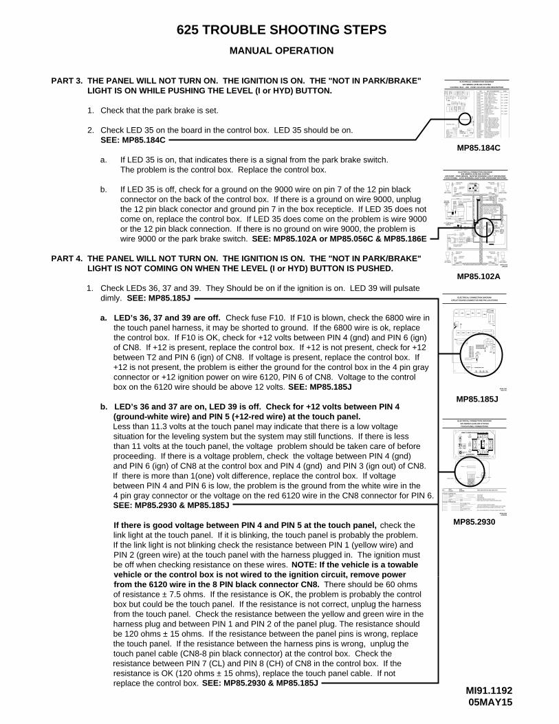
Check that the park brake is set.
MP85.184C
AIR DUMP - PARK BRAKE - MASTER WARNING LIGHT AND BUZZERTOUCH PANEL - JACK WARNING LIGHTS AND PRESSURE SWITCHES
RIGHT REAR
MP85.102A
GRAY12 PIN
PILOT DUMPCONNECTIONBY OEM
RIGHT FRONT
TOUCH PANEL
TO IGNITION
WARNING
WARNING
GROUNDTO HWH
_
MP85.102A
TO ACCESSORY
LEFT REAR
42004000
AB
SWITCH
6235
PILOT AIR DUMPCONNECTION
62316230
93009301
STUD
PRESSURESWITCH
LEFT FRONT
LIGHTWARNINGMASTER
DIODE
DIODE
7699
6111
PARK BRAKESWITCH
7699
7699
+
6111
1200
FUSE5AMP
AB
SWITCH
62351000
SWITCH
6110
BUZZER
8 PIN
62309300
6231
9301
CB
A
6235
WARNINGSWITCH
3000
3200
B A
PRESSURESWITCH
BLACK
6120
9000
PARK BRAKELIGHT
9001 - TO90007699
HWH COMPUTERIZED LEVELING
UNDERSTAND OPERATOR’S MANUAL BEFORE USING. BLOCK FRAME AND TIRES
SECURELY BEFORE REMOVING TIRES OR CRAWLING UNDER VEHICLE.
NOT IN
EXCESSSLOPE
BRAKEPARK/
HYD
STORE DUMP
LEVEL
CAUTION!
TRAVELMODEOFF
LEVELING SYSTEM - LEVELING
SEE ELECTRICAL CONNECTION
MANIFOLD - PUMP AND
DIAGRAM - 625 SERIES
MASTER RELAYS
4 PINGRAY
BROWN12 PIN
BLACK12 PIN
12 PINGREEN
SWITCH
6235
SWITCHWARNING
9300
2000
6230 - 62319301
2200
B A
625 SERIES LEVELING SYSTEMELECTRICAL CONNECTION DIAGRAM
PRESSURE PRESSURE
16FEB05
THE PANEL WILL NOT TURN ON. THE IGNITION IS ON. THE "NOT IN PARK/BRAKE"LIGHT IS ON WHILE PUSHING THE LEVEL (I or HYD) BUTTON.
Check LED 35 on the board in the control box. LED 35 should be on.2.
If LED 35 is on, that indicates there is a signal from the park brake switch.a.
b. If LED 35 is off, check for a ground on the 9000 wire on pin 7 of the 12 pin blackconnector on the back of the control box. If there is a ground on wire 9000, unplug
SEE: MP85.184C
SEE: MP85.102A or MP85.056C & MP85.186E
LIGHT IS NOT COMING ON WHEN THE LEVEL (I or HYD) BUTTON IS PUSHED.THE PANEL WILL NOT TURN ON. THE IGNITION IS ON. THE "NOT IN PARK/BRAKE"
Check LEDs 36, 37 and 39. They Should be on if the ignition is on. LED 39 will pulsatedimly. SEE: MP85.185J
the 12 pin black conector and ground pin 7 in the box recepticle. If LED 35 does notcome on, replace the control box. If LED 35 does come on the problem is wire 9000or the 12 pin black connection. If there is no ground on wire 9000, the problem iswire 9000 or the park brake switch.
SEE: MP85.185J
Check fuse F10. If F10 is blown, check the 6800 wire ina. LED’s 36, 37 and 39 are off.
than 11 volts at the touch panel, the voltage problem should be taken care of before
and PIN 6 (ign) of CN8 at the control box and PIN 4 (gnd) and PIN 3 (ign out) of CN8.
between PIN 4 and PIN 6 is low, the problem is the ground from the white wire in the 4 pin gray connector or the voltage on the red 6120 wire in the CN8 connector for PIN 6.
b. LED’s 36 and 37 are on, LED 39 is off. Check for +12 volts between PIN 4 (ground-white wire) and PIN 5 (+12-red wire) at the touch panel.Less than 11.3 volts at the touch panel may indicate that there is a low voltage situation for the leveling system but the system may still functions. If there is less
proceeding. If there is a voltage problem, check the voltage between PIN 4 (gnd)
If there is more than 1(one) volt difference, replace the control box. If voltage
SEE: MP85.2930 & MP85.185J
SEE: MP85.2930 & MP85.185J
SW GND FROM TOUCH PANEL FOR LEVEL LED
SW +12V FROM SW TO TOUCH PANEL FOR LEVEL
SW +12V FROM SW TO TOUCH PANEL FOR STORE
SWITCHED BATTERY FROM CONTROL BOX
WIRE DESCRIPTION AND FUNCTION
MP85.185J
MP85.2930
6 PIN UML CONNECTOR
5 PIN MTA CONNECTOR
2
5
34
6
1
PIN #
3
54
21
WIRE
REDWHITE
COLOR
GREENYELLOW
LINK LIGHT
NO CONNECTIONACCESSORY
NO CONNECTIONLEVEL
STORELED
WIRE NUMBER
62306800
+12V ACC FROM TOUCH PANEL
GROUND FROM CONTROL BOXCAN SHIELD
CAN HIGHCAN LOW
PIN 4 PIN 1
MP85.293022FEB05
EXTEND
RETRACT
HWH COMPUTERIZED LEVELING
SECURELY BEFORE REMOVING TIRES OR CRAWLING UNDER VEHICLE.UNDERSTAND OPERATOR’S MANUAL BEFORE USING. BLOCK FRAME AND TIRES
TOUCH PANEL CONNECTIONS
625 SERIES LEVELING SYSTEM
EMERGENCY
PIN 1
STOPMODE
TRAVEL
CAUTION!
MANUALDUMPSTORE
AUTO
AUTOLEVEL
SLOPE
NOT INPARK/BRAKE
EXCESS
R
RETRACT
MANUAL
EXTEND
ELECTRICAL CONNECTION DIAGRAM
CONTROL BOX - LED - FUSE LOCATION AND DESCRIPTION
625 SERIES LEVELING SYSTEM
ELECTRICAL CONNECTION DIAGRAM
+12VREAR
FRONT
GROUND
RIGHT SIDE
LEFT SIDE
LOCATION
9
BOARDOLD
(39)
383736
36
F12
3837
SENSING UNIT
F2F1
FUSE
LED
2
DU
MP
4
12
11
RIG
HT
RE
AR
1 3
RE
AR
LEF
T
F319
F4
32
F9
22
27
28
26
24
25
23
21 29 3130
15
16
MA
ST
ER
RE
LAY
RE
LAY
F6
13
14F
7
6
PU
MP
TR
AV
EL
F8 18
17
8
F10
33 34 35
(F11)
PF
4P
F3
20
RIG
HT
CR
X2
FR
ON
T
5
FR
ON
TLE
FT
7
CR
X1
LEFT REAR PRESS SW28-RED
PARK BRAKEJACK INTERRUPT50 LB PRESS SW INPUTMASTER WARN CONTROL3000 LB PRESS SW INPUTNOT USEDNOT USED
33-GREEN
31-GREEN30-YELLOW
35-RED34-RED
32-RED
29-RED
LEFT REAR OUTPUT
RIGHT REAR PRESS SWRIGHT FRONT PRESS SWLEFT FRONT PRESS SWLEFT REAR WARN SWRIGHT REAR WARN SWRIGHT FRONT WARN SWLEFT FRONT WARN SW
CRX 2TRAVEL OUTPUTTRAVEL COILPUMP OUTPUTPUMP COILMASTER RELAY OUTPUTMASTER RELAY COILDUMP OUTPUTDUMP COILLEFT FRONT OUTPUTLEFT FRONT COILRIGHT FRONT OUTPUTRIGHT FRONT COIL
17-YELLOW
24-YELLOW23-YELLOW22-YELLOW21-YELLOW20-YELLOW19-YELLOW
27-RED26-RED25-RED
18-RED
CRX 1
15-YELLOW
13-YELLOW
11-YELLOW
7-YELLOW
5-YELLOW
12-RED
16-RED
14-RED
8-RED
6-RED
LEFT REAR COILRIGHT REAR OUTPUTRIGHT REAR COIL
RELAY DESCRIPTION
3-YELLOW
1-YELLOW
4-RED
2-RED
LED
F2 - 15 AMP
F9 - 5 AMP
F8 - 5 AMP
F7 - 5 AMP
F6 - 5 AMP
F4 - 15 AMP
F3 - 15 AMP
F1 - 15 AMP
FUSE
CIRCUIT BOARD CONNECTOR AND PIN LOCATIONS
CR8
CN1
ELECTRICAL CONNECTION DIAGRAM
A32433- 5
12
LD23 Y
LD28LD27LD26LD25LD24
R
RR
RY
LD22LD21
YY
CR6
CR2
CN6
CR5
CR1
GN
D PF1
CR7
1
CR10CR3
(SHIELD)
LD38
PROGRAM CHIP
LD36R
LD39R
LD37R
CN9
T2
LD
29
R
LD
31L
D30
Y G LD
35
LD
33L
D32
R G
LD
34
R R
R
8
F10
GND
IGN CL CH
PF4
PF3
CN8
08OCT07MP85.185J
CR9
CR4CR11
1
12
IGN OUT
GND AUX
1
CN7
12
CN3
1
+12
from the 6120 wire in the 8 PIN black connector CN8.
be off when checking resistance on these wires.
box but could be the touch panel. If the resistance is not correct, unplug the harness
vehicle or the control box is not wired to the ignition circuit, remove power
link light at the touch panel. If it is blinking, the touch panel is probably the problem.If the link light is not blinking check the resistance between PIN 1 (yellow wire) and
from the touch panel. Check the resistance between the yellow and green wire in the
the touch panel. If the resistance between the harness pins is wrong, unplug the touch panel cable (CN8-8 pin black connector) at the control box. Check the
If there is good voltage between PIN 4 and PIN 5 at the touch panel,
PIN 2 (green wire) at the touch panel with the harness plugged in. The ignition must
of resistance ± 7.5 ohms. If the resistance is OK, the problem is probably the control
harness plug and between PIN 1 and PIN 2 of the panel plug. The resistance shouldbe 120 ohms ± 15 ohms. If the resistance between the panel pins is wrong, replace
resistance between PIN 7 (CL) and PIN 8 (CH) of CN8 in the control box. If the resistance is OK (120 ohms ± 15 ohms), replace the touch panel cable. If not replace the control box.
There should be 60 ohms
NOTE: If the vehicle is a towable
check the
the touch panel harness, it may be shorted to ground. If the 6800 wire is ok, replace the control box. If F10 is OK, check for +12 volts between PIN 4 (gnd) and PIN 6 (ign) of CN8. If +12 is present, replace the control box. If +12 is not present, check for +12 between T2 and PIN 6 (ign) of CN8. If voltage is present, replace the control box. If +12 is not present, the problem is either the ground for the control box in the 4 pin gray connector or +12 ignition power on wire 6120, PIN 6 of CN8. Voltage to the control box on the 6120 wire should be above 12 volts.
The problem is the control box. Replace the control box.

MI91.120323OCT07
625 TROUBLE SHOOTING STEPS
MANUAL OPERATION
MP85.184C
Check
good voltage, the problem is the touch panel cable or it’s connections. If there is no voltage between pins 3 and 4, check for voltage on the legs of poly fuse PF3. If there is no voltage on either leg, replace the control box. If there is voltage on one leg of
present, replace the touch panel. If there is still no voltage, remove the 6800 wire from the CN8 connector and recheck pins 3 and 4. If there is voltage now, the 6800 wire is
voltage between PIN 4 (gnd) and PIN 6 (ign) of CN8 at the control box. If there is less than 12 volts present, check the ground and ignition supply connections for
PART 5. THE PUMP STARTS TO RUN WHEN THE TOUCH PANEL IS TURNED ON.
If LEDs 15 and/or 16 are off replace the pump relay.
If LEDs 15 and/or 16 are on, replace the control box.
Check LEDs 15 (YELLOW) and 16 (RED)
any problems including corrosion. If there is good voltage between pins 4 and 6,
The pump relay contacts are stuck.
SEE: MP85.185J
b.
SEE: MP85.184C
a.
1.
c. LED 37 is on. LED 36 is off. LED 39 may or may not be on, blinking.
voltage between pins 3 (ign out) and 4 (gnd) of CN8 at the control box. If there is
the poly fuse, unplug the touch panel cable at the touch panel and recheck pins 3 and 4. (It will take about 30 seconds for the poly fuse to reset). If voltage is now
shorted to ground. If voltage is still not present, replace the control box.SEE: MP85.2930 & MP85.185J & MP85.102K
If there is no voltage between PIN 4 and PIN 5 at the touch panel, check for
MP85.102K
PART 4. continued. . .
MP85.2930
LINK LIGHTPIN 4 PIN 1
LD38
ELECTRICAL CONNECTION DIAGRAM
625 SERIES LEVELING SYSTEM
TOUCH PANEL CONNECTIONS
UNDERSTAND OPERATOR’S MANUAL BEFORE USING. BLOCK FRAME AND TIRESSECURELY BEFORE REMOVING TIRES OR CRAWLING UNDER VEHICLE.
HWH COMPUTERIZED LEVELING
MP85.185J
CAUTION!EMERGENCY
LEVEL
PIN 1
AUTOSTORE DUMP
MANUAL
STOP
AUTO
R
RETRACT
BRAKEPARK/NOT IN
TRAVELMODE
MANUAL
EXCESSSLOPE
EXTEND
A32433
LD39
PROGRAM CHIP- 5
RLD37
RLD36
RR
RETRACT
EXTEND
MP85.185J08OCT07
IGN OUT
(SHIELD)
ELECTRICAL CONNECTION DIAGRAM
CIRCUIT BOARD CONNECTOR AND PIN LOCATIONS
CR10
12
CR5 CR6
CN6 1
CR1
GN
D PF1
CR2
CR9CR7 CR8
T2
CN9
LD
29YLD21LD22
LD24LD25LD26LD27LD28
LD23RY
YR
RR
R
Y
CN1
GND
LD
34
LD
32L
D33
LD
30L
D31
GRGY RR LD
35
GND
CR3 CR4CR11
PF3
F10PF4
CN7
AUX
12
1
CHCLIGN8
CN8
CN3
12
1
1
+12
replace the control box.
6230 - TO HWHGROUND STUD
LEVELING MANIFOLD
ELECTRICAL CONNECTION DIAGRAM625 SERIES LEVELING SYSTEM
PUMP AND MASTER RELAYSLEVELING MANIFOLD
PUMPMOTOR
MOTOR
#7
#6
PUMPRELAY
#4
#5
6231 - TO HWHGROUND STUD
TO PUMP
#9
+
8600
HWH GROUND
MANIFOLD
STUD
24007600
34007601
62404400
14006240
TO HWH GROUND STUD - 6240
TO 3000 LB PRESSURE SWITCH - 8100
LEVELING
AB
AB
BA
AB
P.E
.DP
.E.D
P.E
.DP
.E.D
LR
LF
RF
RR
TO 50 LB PRESSURE SWITCH - 8101
HARNESSTOUCH PANEL
BLACK8 PIN
MASTERRELAY
#3
#1
BATTERY
#2
#8
8500
TO HOUSE
6800
22OCT07MP85.102K
BROWN
GRAY4 PIN
12 PIN
WIRE AS A FUSE DOES EXCEPT THE POLY SWITCH WILL ALLOW CURRENT THROUGH WHEN THE OVERLOAD OR SHORT IS REMOVED. POLY SWITCHES ARE NOTREPLACEABLE.
F12 HAVE BEEN REPLACED WITH POLY SWITCHES PF4 NOTE: ON NEWER CONTROL BOXES, FUSE F11 AND FUSE
AND PF3. POLY SWITCHES PROTECT A COMPONENT OR
SYSTEMS.IT IS ONLY USED WITH PILOT OPERATED AIR DUMPVEHICLES EQUIPPED WITH HWH AIR DUMP SYSTEMS.NOTE: THE TRAVEL RELAY IS NOT USED ON
TRAVEL MODE AND THE IGNITION IS ON.WILL BE ON IF THE LEVELING SYSTEM IS IN THE
NOTE: THE TRAVEL RELAY IS WIRED AS A NORMALLY CLOSED RELAY. WHEN THE YELLOWLED (17) IS ON THE RELAY CONTACTS WILL OPEN.THE RED LED (18) WILL NOT BE ON. THE RED LED
CONTROL BOX - LED - FUSE LOCATION AND DESCRIPTION
625 SERIES LEVELING SYSTEM
ELECTRICAL CONNECTION DIAGRAM
LATER LED’S 3 AND 19 WILL TURN OFF.IS PUSHED, LED’s 7 AND 20 WILL TURN OFF. 5 SECONDSPUSHED. TWO SECONDS AFTER THE "STORE" BUTTONTOUCH PANEL IS ON UNLESS THE "STORE" BUTTON ISLED’S 19 AND 20 (YELLOW) WILL BE ON WHENEVER THE
THE CONTROL BOX, TOUCH PANEL OR CONNECTION CABLE.
NOTE: A LIT YELLOW LED INDICATES THERE IS A GROUNDSIGNAL TO TURN THE CORRESPONDING RELAY ON.
A LIT RED LED INDICATES THERE IS VOLTAGE ON IT’S CORRESPONDING OUTPUT PIN.
CORRESPONDING RED LED IS OFF, EITHERIT’S FUSE IS BLOWN OR THE RELAY IS BAD.
IF THE YELLOW LED’S ARE WORKING BUT NO RED LEDIS COMING ON THERE MAY BE PROBLEM WITH INPUT VOLTAGE IN THE 4-PIN CONNECTOR.
IF A YELLOW LED IS NOT LIT, THERE IS A PROBLEM WITH
IF A YELLOW LED IS LIT AND THE
DIAGRAM - CONTROL BOX CONNECTION INFORMATION.PIN CONNECTIONS SEE ELECTRICAL CONNECTIONNOTE: FOR DETAILED INPUT / OUTPUT INFORMATION ABOUT
MP85.184J
+12VREAR
FRONT
GROUND
RIGHT SIDE
LEFT SIDE
LOCATION
9
BOARDOLD
(39)
383736
36
F12
3837
SENSING UNIT
F2F1
FUSE
LED
2
DU
MP
4
12
11
RIG
HT
RE
AR
1 3
RE
AR
LEF
T
F319
F4
32
F9
22
27
28
26
24
25
23
21 29 3130
15
16
MA
ST
ER
RE
LAY
RE
LAY
F6
13
14
F7
6
PU
MP
TR
AV
EL
F8 18
17
8
F10
33 34 35
(F11)
PF
4P
F3
20
RIG
HT
CR
X2
FR
ON
T
5
FR
ON
TLE
FT
7
CR
X1
LEFT REAR PRESS SW28-RED
MASTER WARNINGLINK LIGHT
ACCESSORY OUT FORACCESSORY INBOARD ENABLEPARK BRAKEJACK INTERRUPT50 LB PRESS SW INPUTMASTER WARN CONTROL3000 LB PRESS SW INPUTNOT USEDNOT USED
(39) 9-RED
33-GREEN
31-GREEN30-YELLOW
38-RED37-RED36-RED35-RED34-RED
32-RED
29-RED
23OCT07MP85.184C
PF4 (F11)
F10 - 10 AMP
LEFT REAR OUTPUT
RIGHT REAR PRESS SWRIGHT FRONT PRESS SWLEFT FRONT PRESS SWLEFT REAR WARN SWRIGHT REAR WARN SWRIGHT FRONT WARN SWLEFT FRONT WARN SW
CRX 2TRAVEL OUTPUTTRAVEL COILPUMP OUTPUTPUMP COILMASTER RELAY OUTPUTMASTER RELAY COILDUMP OUTPUTDUMP COILLEFT FRONT OUTPUTLEFT FRONT COILRIGHT FRONT OUTPUTRIGHT FRONT COIL
17-YELLOW
24-YELLOW23-YELLOW22-YELLOW21-YELLOW20-YELLOW19-YELLOW
27-RED26-RED25-RED
18-RED
CRX 1
15-YELLOW
13-YELLOW
11-YELLOW
7-YELLOW
5-YELLOW
12-RED
16-RED
14-RED
8-RED
6-RED
LEFT REAR COILRIGHT REAR OUTPUTRIGHT REAR COIL
RELAY DESCRIPTION
3-YELLOW
1-YELLOW
4-RED
2-RED
LED
F2 - 15 AMP
F9 - 5 AMP
F8 - 5 AMP
F7 - 5 AMP
F6 - 5 AMP
F4 - 15 AMP
F3 - 15 AMP
F1 - 15 AMP
FUSE
MI91.121213APR07
625 TROUBLE SHOOTING STEPS
MANUAL OPERATION
PART 6.
1.
MP85.184C
RIG
HT
NOTE: FOR DETAILED INPUT / OUTPUT INFORMATION ABOUT PIN CONNECTIONS SEE ELECTRICAL CONNECTION DIAGRAM - CONTROLBOX CONNECTION INFORMATION.
IF A YELLOW LED IS LIT AND THE
IF THE YELLOW LED’S ARE WORKING BUT
IT’S FUSE IS BLOWN OR THE RELAY IS BAD.CORRESPONDING RED LED IS OFF, EITHER
VOLTAGE ON IT’S CORRESPONDING OUTPUT PIN.A LIT RED LED INDICATES THERE IS
IS A GROUND SIGNAL TO TURN THE NOTE: A LIT YELLOW LED INDICATES THERE
CORRESPONDING RELAY ON.
PROBLEM WITH INPUT VOLTAGE IN THE NO RED LED IS COMING ON THERE MAY BE
IF A YELLOW LED IS NOT LIT, THERE IS A PROBLEM WITH THE CONTROL BOX, TOUCH PANEL
4-PIN CONNECTOR.
OR CONNECTION CABLE
LEFT SIDEGROUND
RIGHT SIDE
SENSING UNIT
+12V
FRONT
REAR
FUSE
1
2
RE
AR
625 SERIES LEVELING SYSTEM
CONTROL BOX - LED - FUSE LOCATION AND DESCRIPTION
THE RED LED (18) WILL NOT BE ON. THE RED LEDLED (17) IS ON THE RELAY CONTACTS WILL OPEN.NORMALLY CLOSED RELAY. WHEN THE YELLOWNOTE: THE TRAVEL RELAY IS WIRED AS A
WILL BE ON IF THE LEVELING SYSTEM IS IN THE
LED’S 19 AND 20 (YELLOW) WILL BE ON WHENEVER THETOUCH PANEL IS ON UNLESS THE "STORE" BUTTON ISPUSHED. TWO SECONDS AFTER THE "STORE" BUTTONIS PUSHED, LED’s 7 AND 20 WILL TURN OFF. 5 SECONDSLATER LED’S 3 AND 19 WILL TURN OFF.
TRAVEL MODE AND THE IGNITION IS ON.
NOTE: THE TRAVEL RELAY IS NOT USED ONVEHICLES EQUIPPED WITH HWH AIR DUMP SYSTEMS.IT IS ONLY USED WITH PILOT OPERATED AIR DUMP
ACCESSORY INACCESSORY OUT FORMASTER WARNINGLINK LIGHT
MASTER RELAY OUTPUT
RIGHT FRONT OUTPUT
LEFT FRONT WARN SWRIGHT FRONT WARN SWRIGHT REAR WARN SW
3000 LB PRESS SW INPUTMASTER WARN CONTROL50 LB PRESS SW INPUT
RIGHT REAR PRESS SW
LEFT FRONT PRESS SWRIGHT FRONT PRESS SW
CRX 1
JACK INTERRUPT
BOARD ENABLEPARK BRAKE
LEFT REAR PRESS SWNOT USEDNOT USED
LEFT REAR WARN SW
RIGHT REAR OUTPUT
LEFT REAR OUTPUTLEFT REAR COIL
TRAVEL COILTRAVEL OUTPUTCRX 2
LEFT FRONT OUTPUT
MASTER RELAY COILDUMP OUTPUT
PUMP OUTPUT
DUMP COIL
PUMP COIL
LEFT FRONT COIL
RIGHT FRONT COIL
RIGHT REAR COIL
30-YELLOWF12PANEL
39
SYSTEMS.
3736 3831-GREEN
33-GREEN32-RED
34-RED35-RED36-RED
39-RED
38-RED37-RED
FUSE 7.5 AMP
33
+12 ACC TOTOUCH
20P
UM
PR
ELA
Y
TR
AV
EL
MA
ST
ER
RE
LAY
DU
MP
PIN 1
22
21
27
28
25
26
24
23
29 30 31 32
3
4
LED
F1
F6
11 13
12 14
F2 19
LEF
T
CR
X2
RE
AR
5
F7 15
6
16
7F
8 18
17
F9
8
F3
F4
LEF
TF
RO
NT
RIG
HT
FR
ON
T
13-YELLOW
34 35
F10
F11
15-YELLOW
17-YELLOW
19-YELLOW
14-RED
16-RED
18-RED
24-YELLOW
29-RED
25-RED26-RED27-RED28-RED
21-YELLOW22-YELLOW23-YELLOW
20-YELLOW
CR
X1
LED
3-YELLOW2-RED
4-RED
7-YELLOW
11-YELLOW8-RED
12-RED
6-RED5-YELLOW
1-YELLOW
MP85.184C27APR05
F11 - 3 AMP
F10 - 10 AMP
FUSE
F1 - 15 AMP
F2 - 15 AMP
F9 - 5 AMP
F4 - 15 AMP
F6 - 5 AMP
F7 - 5 AMP
F8 - 5 AMP
F3 - 15 AMP
RELAY DESCRIPTION
ELECTRICAL CONNECTION DIAGRAM
MP85.102K
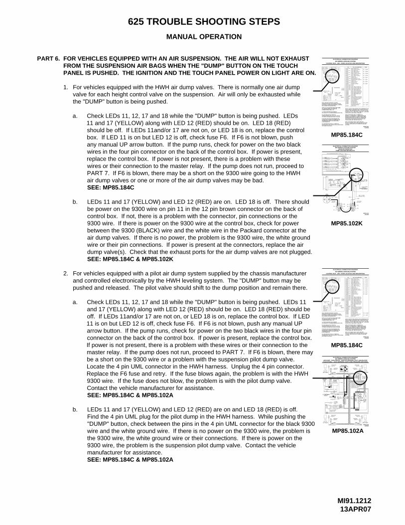
FOR VEHICLES EQUIPPED WITH AN AIR SUSPENSION. THE AIR WILL NOT EXHAUST FROM THE SUSPENSION AIR BAGS WHEN THE "DUMP" BUTTON ON THE TOUCHPANEL IS PUSHED. THE IGNITION AND THE TOUCH PANEL POWER ON LIGHT ARE ON.
For vehicles equipped with the HWH air dump valves. There is normally one air dumpvalve for each height control valve on the suspension. Air will only be exhausted whilethe "DUMP" button is being pushed.
a.
b. LEDs 11 and 17 (YELLOW) and LED 12 (RED) are on. LED 18 is off. There shouldbe power on the 9300 wire on pin 11 in the 12 pin brown connector on the back ofcontrol box. If not, there is a problem with the connector, pin connections or the9300 wire. If there is power on the 9300 wire at the control box, check for powerbetween the 9300 (BLACK) wire and the white wire in the Packard connector at theair dump valves. If there is no power, the problem is the 9300 wire, the white groundwire or their pin connections. If power is present at the connectors, replace the airdump valve(s). Check that the exhaust ports for the air dump valves are not plugged.
2. For vehicles equipped with a pilot air dump system supplied by the chassis manufacturerand controlled electronically by the HWH leveling system. The "DUMP" button may bepushed and released. The pilot valve should shift to the dump position and remain there.
a.
b. LEDs 11 and 17 (YELLOW) and LED 12 (RED) are on and LED 18 (RED) is off.Find the 4 pin UML plug for the pilot dump in the HWH harness. While pushing the"DUMP" button, check between the pins in the 4 pin UML connector for the black 9300wire and the white ground wire. If there is no power on the 9300 wire, the problem isthe 9300 wire, the white ground wire or their connections. If there is power on the9300 wire, the problem is the suspension pilot dump valve. Contact the vehiclemanufacturer for assistance.
SEE: MP85.184C
SEE: MP85.184C & MP85.102K
SEE: MP85.184C & MP85.102A
GROUND
+12V
CORRESPONDING RELAY ON.
LEFT SIDE
4-PIN CONNECTOR.
OR CONNECTION CABLE
NOTE: FOR DETAILED INPUT / OUTPUT INFORMATION ABOUT PIN CONNECTIONS SEE ELECTRICAL CONNECTION DIAGRAM - CONTROLBOX CONNECTION INFORMATION.
IF A YELLOW LED IS LIT AND THE
IF THE YELLOW LED’S ARE WORKING BUT
IT’S FUSE IS BLOWN OR THE RELAY IS BAD.CORRESPONDING RED LED IS OFF, EITHER
VOLTAGE ON IT’S CORRESPONDING OUTPUT PIN.A LIT RED LED INDICATES THERE IS
IS A GROUND SIGNAL TO TURN THE NOTE: A LIT YELLOW LED INDICATES THERE
PROBLEM WITH INPUT VOLTAGE IN THE NO RED LED IS COMING ON THERE MAY BE
IF A YELLOW LED IS NOT LIT, THERE IS A PROBLEM WITH THE CONTROL BOX, TOUCH PANEL
RE
AR
24
LEFT FRONT PRESS SW
PARK BRAKE
NOT USEDNOT USED
LINK LIGHT
ACCESSORY INACCESSORY OUT FORMASTER WARNING
3000 LB PRESS SW INPUTMASTER WARN CONTROL50 LB PRESS SW INPUT
RIGHT REAR PRESS SW
JACK INTERRUPT
BOARD ENABLE
LEFT REAR PRESS SW
RIGHT FRONT PRESS SW
MP85.184C
THE RED LED (18) WILL NOT BE ON. THE RED LEDLED (17) IS ON THE RELAY CONTACTS WILL OPEN.NORMALLY CLOSED RELAY. WHEN THE YELLOWNOTE: THE TRAVEL RELAY IS WIRED AS A
WILL BE ON IF THE LEVELING SYSTEM IS IN THE
LED’S 19 AND 20 (YELLOW) WILL BE ON WHENEVER THETOUCH PANEL IS ON UNLESS THE "STORE" BUTTON ISPUSHED. TWO SECONDS AFTER THE "STORE" BUTTONIS PUSHED, LED’s 7 AND 20 WILL TURN OFF. 5 SECONDSLATER LED’S 3 AND 19 WILL TURN OFF.
TRAVEL MODE AND THE IGNITION IS ON.
NOTE: THE TRAVEL RELAY IS NOT USED ONVEHICLES EQUIPPED WITH HWH AIR DUMP SYSTEMS.IT IS ONLY USED WITH PILOT OPERATED AIR DUMP
FUSE 7.5 AMP+12 ACC TO
SENSING UNIT
RIGHT SIDE
PIN 1
FRONT
REAR
39
25
27
28
26
PANELTOUCH
SYSTEMS.
25-RED
32-RED
34-RED35-RED
29-RED
27-RED28-RED
39-RED
38-RED37-RED36-RED
26-RED
30-YELLOW31-GREEN
33-GREEN
F12
36 3837
MP85.184C27APR05
F10 - 10 AMP
F11 - 3 AMP
RIGHT REAR OUTPUT
LEFT REAR OUTPUTLEFT REAR COIL
RIGHT REAR COIL
RELAY DESCRIPTION
DUMP COIL
PUMP COIL
CRX 1
TRAVEL COIL
CRX 2
MASTER RELAY OUTPUT
RIGHT FRONT OUTPUT
LEFT FRONT WARN SWRIGHT FRONT WARN SWRIGHT REAR WARN SWLEFT REAR WARN SW
TRAVEL OUTPUT
LEFT FRONT OUTPUT
MASTER RELAY COILDUMP OUTPUT
PUMP OUTPUT
LEFT FRONT COIL
RIGHT FRONT COIL
625 SERIES LEVELING SYSTEM
CONTROL BOX - LED - FUSE LOCATION AND DESCRIPTION
ELECTRICAL CONNECTION DIAGRAM
MA
ST
ER
RE
LAY
DU
MP
31
FUSE
LED
2 4
F1 19
F6
11 13
12 14
F2
TR
AV
EL
PU
MP
RE
LAY
2922
21
23
3330 31 32
5
F7 15
16
F8
6
F3
7
18
17
F9
208
F4
LEF
T
RIG
HT
RE
AR
CR
X2
RIG
HT
FR
ON
T
LEF
TF
RO
NT
3-YELLOW4-RED
8-RED
6-RED
24-YELLOW
21-YELLOW22-YELLOW23-YELLOW
20-YELLOW
7-YELLOW
5-YELLOW
F10
3534
F11
15-YELLOW
17-YELLOW
19-YELLOW18-RED
16-RED
13-YELLOW
11-YELLOW
14-RED
12-RED
2-RED
CR
X1
1-YELLOW
LED
F9 - 5 AMP
F8 - 5 AMP
F2 - 15 AMP
F4 - 15 AMP
F6 - 5 AMP
F7 - 5 AMP
F3 - 15 AMP
F1 - 15 AMP
FUSE
MASTERWARNING
LEFT FRONT
LIGHT
SWITCH
LEFT REAR
PARK BRAKE
TOUCH PANEL - JACK WARNING LIGHTS AND PRESSURE SWITCHESAIR DUMP - PARK BRAKE - MASTER WARNING LIGHT AND BUZZER
MP85.102A
WARNING
DIAGRAM - 625 SERIES
MANIFOLD - PUMP AND MASTER RELAYS
6230 - 6231
SWITCH
SEE ELECTRICAL CONNECTION
LEVELING SYSTEM - LEVELING
SWITCHWARNING
LIGHT
93009301
62306231
WARNING
4000
AB
4200
SWITCH
6235
PILOT AIR DUMPCONNECTION
SWITCHPRESSURE
93019300
62306231
STUD
TO HWHGROUND
AB
C
TO IGNITION
TO ACCESSORY
9001 - TOPARK BRAKE
6111
7699
DIODE
DIODE
5AMP
6111
7699
7699
9000
BUZZER
+ _
SWITCHPRESSURE
1000
6110
AB
1200
FUSE
SWITCH
6235
WARNING
90007699
6120
UNDERSTAND OPERATOR’S MANUAL BEFORE USING. BLOCK FRAME AND TIRES
DUMPSTORE
CAUTION!
SECURELY BEFORE REMOVING TIRES OR CRAWLING UNDER VEHICLE.
MODEOFF
TRAVEL
HWH COMPUTERIZED LEVELING
TOUCH PANEL
PARK/
LEVEL SLOPEEXCESS
NOT IN
HYD
BRAKE
GRAY
62353000
AB
3200
RIGHT REAR
MP85.102A16FEB05
BLACK8 PIN
PRESSURESWITCH
12 PINGRAY
12 PINBLACK4 PIN
BROWN12 PIN
12 PINGREEN
62352000
93019300
AB
2200
PRESSURESWITCH
RIGHT FRONT
PILOT DUMPCONNECTIONBY OEM
ELECTRICAL CONNECTION DIAGRAM625 SERIES LEVELING SYSTEM
SEE: MP85.184C & MP85.102A
LEVELING MANIFOLD
ELECTRICAL CONNECTION DIAGRAM625 SERIES LEVELING SYSTEM
PUMP AND MASTER RELAYSLEVELING MANIFOLD
PUMPMOTOR
MOTOR
#7
#6
PUMPRELAY
#4
#5
TO PUMP
#9
+
8600
HWH GROUND
MANIFOLD
STUD
TO HWH GROUND STUD - 6240
TO 3000 LB PRESSURE SWITCH - 8100
TO 50 LB PRESSURE SWITCH - 8101
1400
44006240
6240
AB
AB
24007600
7601
BA
AB
3400
LEVELING
P.E
.DP
.E.D
P.E
.DP
.E.D
RF
RR
LR
LF
HARNESSTOUCH PANEL
GROUND STUD6230 - TO HWH
BLACK8 PIN
MASTERRELAY
#3
#1
BATTERY
#2
#8
8500
TO HOUSE
6800
14JUN05MP85.102K
BROWN
GRAY4 PIN
12 PIN
Check LEDs 11, 12, 17 and 18 while the "DUMP" button is being pushed. LEDs 11 and 17 (YELLOW) along with LED 12 (RED) should be on. LED 18 (RED) should be off. If LEDs 11and/or 17 are not on, or LED 18 is on, replace the control box. If LED 11 is on but LED 12 is off, check fuse F6. If F6 is not blown, push any manual UP arrow button. If the pump runs, check for power on the two black wires in the four pin connector on the back of the control box. If power is present, replace the control box. If power is not present, there is a problem with these wires or their connection to the master relay. If the pump does not run, proceed to PART 7. If F6 is blown, there may be a short on the 9300 wire going to the HWHair dump valves or one or more of the air dump valves may be bad.
Check LEDs 11, 12, 17 and 18 while the "DUMP" button is being pushed. LEDs 11 and 17 (YELLOW) along with LED 12 (RED) should be on. LED 18 (RED) should be off. If LEDs 11and/or 17 are not on, or LED 18 is on, replace the control box. If LED 11 is on but LED 12 is off, check fuse F6. If F6 is not blown, push any manual UP arrow button. If the pump runs, check for power on the two black wires in the four pin connector on the back of the control box. If power is present, replace the control box. If power is not present, there is a problem with these wires or their connection to the master relay. If the pump does not run, proceed to PART 7. If F6 is blown, there may be a short on the 9300 wire or a problem with the suspension pilot dump valve. Locate the 4 pin UML connector in the HWH harness. Unplug the 4 pin connector. Replace the F6 fuse and retry. If the fuse blows again, the problem is with the HWH 9300 wire. If the fuse does not blow, the problem is with the pilot dump valve. Contact the vehicle manufacturer for assistance.

MI91.122208OCT07
625 TROUBLE SHOOTING STEPS
MANUAL OPERATION
1.
MP85.184C
RIG
HT
NOTE: FOR DETAILED INPUT / OUTPUT INFORMATION ABOUT PIN CONNECTIONS SEE ELECTRICAL CONNECTION DIAGRAM - CONTROLBOX CONNECTION INFORMATION.
IF A YELLOW LED IS LIT AND THE
IF THE YELLOW LED’S ARE WORKING BUT
IT’S FUSE IS BLOWN OR THE RELAY IS BAD.CORRESPONDING RED LED IS OFF, EITHER
VOLTAGE ON IT’S CORRESPONDING OUTPUT PIN.A LIT RED LED INDICATES THERE IS
IS A GROUND SIGNAL TO TURN THE NOTE: A LIT YELLOW LED INDICATES THERE
CORRESPONDING RELAY ON.
PROBLEM WITH INPUT VOLTAGE IN THE NO RED LED IS COMING ON THERE MAY BE
IF A YELLOW LED IS NOT LIT, THERE IS A PROBLEM WITH THE CONTROL BOX, TOUCH PANEL
4-PIN CONNECTOR.
OR CONNECTION CABLE
LEFT SIDEGROUND
RIGHT SIDE
SENSING UNIT
+12V
FRONT
REAR
FUSE
1
2
RE
AR
625 SERIES LEVELING SYSTEM
CONTROL BOX - LED - FUSE LOCATION AND DESCRIPTION
THE RED LED (18) WILL NOT BE ON. THE RED LEDLED (17) IS ON THE RELAY CONTACTS WILL OPEN.NORMALLY CLOSED RELAY. WHEN THE YELLOWNOTE: THE TRAVEL RELAY IS WIRED AS A
WILL BE ON IF THE LEVELING SYSTEM IS IN THE
LED’S 19 AND 20 (YELLOW) WILL BE ON WHENEVER THETOUCH PANEL IS ON UNLESS THE "STORE" BUTTON ISPUSHED. TWO SECONDS AFTER THE "STORE" BUTTONIS PUSHED, LED’s 7 AND 20 WILL TURN OFF. 5 SECONDSLATER LED’S 3 AND 19 WILL TURN OFF.
TRAVEL MODE AND THE IGNITION IS ON.
NOTE: THE TRAVEL RELAY IS NOT USED ONVEHICLES EQUIPPED WITH HWH AIR DUMP SYSTEMS.IT IS ONLY USED WITH PILOT OPERATED AIR DUMP
ACCESSORY INACCESSORY OUT FORMASTER WARNINGLINK LIGHT
MASTER RELAY OUTPUT
RIGHT FRONT OUTPUT
LEFT FRONT WARN SWRIGHT FRONT WARN SWRIGHT REAR WARN SW
3000 LB PRESS SW INPUTMASTER WARN CONTROL50 LB PRESS SW INPUT
RIGHT REAR PRESS SW
LEFT FRONT PRESS SWRIGHT FRONT PRESS SW
CRX 1
JACK INTERRUPT
BOARD ENABLEPARK BRAKE
LEFT REAR PRESS SWNOT USEDNOT USED
LEFT REAR WARN SW
RIGHT REAR OUTPUT
LEFT REAR OUTPUTLEFT REAR COIL
TRAVEL COILTRAVEL OUTPUTCRX 2
LEFT FRONT OUTPUT
MASTER RELAY COILDUMP OUTPUT
PUMP OUTPUT
DUMP COIL
PUMP COIL
LEFT FRONT COIL
RIGHT FRONT COIL
RIGHT REAR COIL
30-YELLOWF12PANEL
39
SYSTEMS.
3736 3831-GREEN
33-GREEN32-RED
34-RED35-RED36-RED
39-RED
38-RED37-RED
FUSE 7.5 AMP
33
+12 ACC TOTOUCH
20
PU
MP
RE
LAY
TR
AV
EL
MA
ST
ER
RE
LAY
DU
MP
PIN 1
22
21
27
28
25
26
24
23
29 30 31 32
3
4
LEDF
1
F6
11 13
12 14
F2 19
LEF
T
CR
X2
RE
AR
5
F7 15
6
16
7
F8 18
17
F9
8
F3
F4
LEF
TF
RO
NT
RIG
HT
FR
ON
T
13-YELLOW
34 35
F10
F11
15-YELLOW
17-YELLOW
19-YELLOW
14-RED
16-RED
18-RED
24-YELLOW
29-RED
25-RED26-RED27-RED28-RED
21-YELLOW22-YELLOW23-YELLOW
20-YELLOW
CR
X1
LED
3-YELLOW2-RED
4-RED
7-YELLOW
11-YELLOW8-RED
12-RED
6-RED5-YELLOW
1-YELLOW
MP85.184C27APR05
F11 - 3 AMP
F10 - 10 AMP
FUSE
F1 - 15 AMP
F2 - 15 AMP
F9 - 5 AMP
F4 - 15 AMP
F6 - 5 AMP
F7 - 5 AMP
F8 - 5 AMP
F3 - 15 AMP
RELAY DESCRIPTION
ELECTRICAL CONNECTION DIAGRAM
If the pump will not run when one or more UP ARROWS are pushed but other UP ARROWS will run the pump, replace the touch panel.
2. Check LEDs 13 (YELLOW), 14 (RED), 15 (YELLOW) and 16 (RED) while an UP ARROW is being pushed. All four LEDs should be lit. If all four LED’s are
SEE: MP85.184C
lit, both red LEDs should be lit. (Check LEDs while pushing an UP ARROW)replace the control box. If both yellow LEDs area.
b. If F7 is OK, replace the control box. If F7is blown, the 8500 wire going to the master relay is shorted to ground or the masterrelay is bad. Wire 8500 is in pin 1 in the 12 pin brown connector on the back of thecontrol box. Disconnect this wire from the master relay, replace the fuse and retry.If the fuse only blows with the 8500 wire connected to the master relay, the masterrelay is bad. SEE: MP85.102K
c. If F8 is OK, replace the control box. If F8is blown, the 8600 wire going to the pump relay is shorted to ground or the pumprelay is bad. Wire 8600 is on pin 12 in the 12 pin brown connector on the back ofthe control box. Disconnect this wire from the pump relay, replace the fuse and retry. If the fuse only blows with the 8600 wire connected to the pump relay, the pump relay is bad. SEE: MP85.102K
is being pushed. The problem is with the relays or the pump motor.LEDs 13 (YELLOW), 14 (RED), 15 (YELLOW) and 16 (RED) are lit when an UP ARROW
SEE: MP85.184C3.
RE
AR
MP85.184C
ELECTRICAL CONNECTION DIAGRAM
RELAY DESCRIPTION
RIGHT REAR COIL
RIGHT FRONT COIL
LEFT FRONT COIL
PUMP COIL
DUMP COIL
PUMP OUTPUT
DUMP OUTPUTMASTER RELAY COIL
LEFT FRONT OUTPUT
TRAVEL OUTPUTTRAVEL COIL
LEFT REAR COILLEFT REAR OUTPUT
RIGHT REAR OUTPUT
RIGHT FRONT OUTPUT
MASTER RELAY OUTPUT
CONTROL BOX - LED - FUSE LOCATION AND DESCRIPTION
625 SERIES LEVELING SYSTEM
MA
ST
ER
DU
MP
RE
LAY
F1
LED
4
3
2
1
FUSE
19
F2
1412
1311
F6
TR
AV
EL
RE
LAY
PU
MP
F3
F8
16
6
15
F7
5
F48
F9
17
18
7
20
LEF
TR
EA
R
RIG
HT
CR
X2
FR
ON
TR
IGH
T
FR
ON
TLE
FT
3-YELLOW
5-YELLOW6-RED
8-RED7-YELLOW
4-RED
17-YELLOW
15-YELLOW
18-RED
16-RED
11-YELLOW
13-YELLOW12-RED
14-RED
2-RED
CR
X1
1-YELLOW
LED
F8 - 5 AMP
F9 - 5 AMP
F3 - 15 AMP
F7 - 5 AMP
F6 - 5 AMP
F4 - 15 AMP
F2 - 15 AMP
F1 - 15 AMP
FUSE
a. Terminals 1, 2, 3, 4, 5, 6 and 9 should all have power when above LEDs are lit.Terminals 7 and 8 should be connected to the ground stud on the side of the pump.Make sure all terminals are tight and that the wires, ring terminals and the relayterminals are free of corrosion. SEE: MP85.1035
GROUND STUD6230 - TO HWH
LEVELING MANIFOLD
ELECTRICAL CONNECTION DIAGRAM625 SERIES LEVELING SYSTEM
PUMP AND MASTER RELAYS WITH PILOT AIR DUMPLEVELING MANIFOLD
MOTORPUMP
MOTOR
#7
#6
RELAYPUMP
#4
#5
6231 - TO HWH
#9
GROUND STUD
TO PUMP+
8600
HWH GROUND
MANIFOLD
STUD
TO HWH GROUND STUD - 6240TO 3000 LB PRESSURE SWITCH - 8100
TO 50 LB PRESSURE SWITCH - 8101
1400
44006240
6240
AB
AB
24007600
7601
BA
AB
3400
MANIFOLD NOT SHOWNNOTE: ROOM EXTENSION
LEVELING
P.E
.DP
.E.D
P.E
.DP
.E.D
RF
RR
LR
LF
BLACK8 PIN
RELAYMASTER
#1
#3
#8
#2
BATTERY
8500 6800
TO +12V
6100
27APR05MP85.1035
12 PINGRAY
GROUND STUDTO HWH
SYSTEM - AIR DUMP625 SERIES LEVELINGDIAGRAMCONNECTIONSEE ELECTRICAL
12 PINBLACK
BROWN
9300
GRAY4 PIN
12 PIN
6230
9301
MP85.1035
b. If terminal 1 has no power, the problem is the 8500 wire or it’s connections to thecontrol box or to the master relay.
c. If terminal 2 has no power, the problem is the battery cable from the battery supplyor it’s connections to the battery supply or to the master relay.
SEE: MP85.1035
SEE: MP85.1035
d. If terminals 1 and 2 have power, check terminal 8 for ground. If ground is notpresent, the problem is the white ground wire or it’s connections to the ground studor to the master relay. SEE: MP85.1035
e. If terminals 1 and 2 have power and terminal 8 has a ground, check terminal 3 forpower. If there is no power on terminal 3, replace the master relay. SEE: MP85.1035
f. If terminals 1,2 and 3 have power, check terminal 4. If terminal 4 has no power, the problem is the short cable between terminals 3 and 4 or it’s connection to these terminals.
g. If terminal 4 has power, check terminal 5 for power. If terminal 5 has no power, the problem is the 8600 wire or it’s connections to the control box or to the pump relay.
h. If terminal 5 has power, check terminal 7 for ground. If a ground is not present, the problem isthe white ground wire or it’s connections to the ground stud or to the pump relay.
SEE: MP85.1035
i. If terminal 5 has power and terminal 7 has a ground, check terminal 6 for power.If terminal 6 does not have power, replace the pump relay.
SEE: MP85.1035
SEE: MP85.1035
SEE: MP85.1035
j. If terminal 6 has power, check terminal 9 on the pump motor. If terminal 9 has no power, the problem is theshort cable between the pump relay and the pump motor or it’s connections. If terminal 9 has power, makesure the power unit assembly has a good frame mounting. The pump motor is internally grounded and the mounting of the assembly supplies the ground for the motor. Make sure the stud on the pump motor istight. If all connections, mountings and wires are OK, replace the pump motor. SEE: MP85.1035
MASTERRELAY
MP85.102K
RELAYPUMP
MOTOR
#6
#7
HWH GROUNDSTUD
PUMPMOTOR
+ TO PUMP
#98600
#4
#5
#3
#1
8500
MP85.102K14JUN05
BATTERY
#2
#8
GROUND STUD6230 - TO HWH
TO HOUSE
6800
HARNESSTOUCH PANEL
ELECTRICAL CONNECTION DIAGRAM625 SERIES LEVELING SYSTEM
PUMP AND MASTER RELAYS
TO 3000 LB PRESSURE SWITCH - 8100
TO 50 LB PRESSURE SWITCH - 8101
LEVELING MANIFOLD
1400
TO HWH GROUND STUD - 6240
MANIFOLDLEVELING
AB
AB
44006240
6240
P.E
.DP
.E.D
AB
BA
34007601
24007600
P.E
.DP
.E.D
LR
LF
LEVELING MANIFOLD
RR
RF
BROWN12 PIN
4 PINGRAY
8 PINBLACK
lit, proceed to #3.
If red LED 14 is not lit, check fuse F7.
If red LED 16 is not lit, check fuse F8.
If either yellow LED is not lit,
(EXTEND) BUTTON IS PUSHED. THE ON LIGHT IS ON.THE PUMP WILL NOT RUN OR RUNS ERRATICALLY WHEN AN UP ARROW PART 7.
IMPORTANT: THE DEFINITION OF POWER IS 10.0 VOLTS OR MORE ATTHE MASTER AND PUMP RELAYS WITH LEDs 13, 14, 15 AND 16 ON.
The pump runs erratically or slowly. Review number 3 of PART 7.4.

MI91.123222OCT07
625 TROUBLE SHOOTING STEPS
MANUAL OPERATION
PART 8.
1.
MP85.184C
RIG
HT
FUSE
1
2
RE
AR
625 SERIES LEVELING SYSTEM
CONTROL BOX - LED - FUSE LOCATION AND DESCRIPTION
MASTER RELAY OUTPUT
RIGHT FRONT OUTPUT
RIGHT REAR OUTPUT
LEFT REAR OUTPUTLEFT REAR COIL
TRAVEL COILTRAVEL OUTPUT
LEFT FRONT OUTPUT
MASTER RELAY COILDUMP OUTPUT
PUMP OUTPUT
DUMP COIL
PUMP COIL
LEFT FRONT COIL
RIGHT FRONT COIL
RIGHT REAR COIL
20
PU
MP
RE
LAY
TR
AV
EL
MA
ST
ER
RE
LAY
DU
MP
3
4
LED
F1
F6
11 13
12 14
F2 19
LEF
T
CR
X2
RE
AR
5
F7 15
6
16
7
F8 18
17
F9
8
F3
F4
LEF
TF
RO
NT
RIG
HT
FR
ON
T
13-YELLOW
15-YELLOW
17-YELLOW
14-RED
16-RED
18-RED
CR
X1
LED
3-YELLOW2-RED
4-RED
7-YELLOW
11-YELLOW8-RED
12-RED
6-RED5-YELLOW
1-YELLOW
FUSE
F1 - 15 AMP
F2 - 15 AMP
F9 - 5 AMP
F4 - 15 AMP
F6 - 5 AMP
F7 - 5 AMP
F8 - 5 AMP
F3 - 15 AMP
RELAY DESCRIPTION
ELECTRICAL CONNECTION DIAGRAM
WHEN PUSHING ANY UP ARROW (EXTEND) BUTTON, NO JACKS WILL EXTEND,THE PUMP RUNS UNDER A LOAD.
The shuttle valve must shift and the control box must see the 50 p.s.i. manifold pressure switch before the control box will allow any solenoid valves to open.
a. Check yellow LEDs 19 and 20. If either LED is not lit, replace the control box.
b. Check yellow LEDs 1 (right rear solenoid valve), 3 (left rear solenoid valve),
SEE: MP85.184C
5 (right front solenoid valve) and 7 (right rear solenoid valve). If these LEDs arecoming on when UP ARROWS are being pushed, the shuttle valve and the 50 p.s.i.switch are functioning properly. The red LEDs 2 (right rear solenoid valve), 4 (left rear solenoid valve), 6 (right front solenoid valve) and 8 (left front solenoid valve)should come on. The LEDs will come on with their respective UP ARROWS as follows:FRONT UP ARROWREAR UP ARROWRIGHT SIDE UP ARROWLEFT SIDE UP ARROW
LEDs 5 and 7 (YELLOW) and LEDs 6 and 8 (RED)LEDs 1 and 3 (YELLOW) and LEDs 2 and 4 (RED)LEDs 1 and 5 (YELLOW) and LEDs 2 and 6 (RED)LEDs 3 and 7 (YELLOW) and LEDs 4 and 8 (RED) SEE: MP85.184C
c. If the red LEDs are not coming on, the 6800 wire going to the 4 pin gray connector on the back of thecontrol box may be the problem. Check fuses F1, F2, F3 and F4. If these fuses are blown, the solenoidvalves may be bad. Whenever the system is on, the 6800 wire should have power on it. The 6800 wireconnects to terminal 3 of the master relay. If there is no power on the 6800 wire, the problem is with the6800 wire or it’s connections to the control box or to the master relay. If the pump runs, the master relayis good. If the pump does not run, refer to PART 7, 2a. and 2b. If there is power on the 6800 wire, fusesF1, F2, F3 and F4 are OK and the red LEDs will not come on, replace the control box.
d. If the red LEDs are coming on as necessary, this indicates there should be power on theappropriate output pins for the solenoid valves. There is most likely a problem with the12 pin brown connector on the back of the control box the wires to the solenoid valvesor their connections.
SEE: MP85.102K
SEE: MP85.102K
2. If yellow LEDs 1,3,5, and 7 are not coming on, (or the yellow LEDs are coming on and the chip is -5 or greater) check LED 33 (GREEN). This LED should be on when the pump is running. This would indicate the control box is receiving a ground signal from the 50 p.s.i.
SEE: MP85.184C
+12V
RE
AR
24
NOT USEDNOT USEDLEFT REAR PRESS SW
RIGHT FRONT PRESS SWLEFT FRONT PRESS SW
RIGHT REAR PRESS SW
MP85.184C
+12 ACC TOFUSE 7.5 AMP
SENSING UNIT
PIN 126
25
28
27
TOUCHPANEL
28-RED27-RED26-RED25-RED
29-RED30-YELLOWF12
ELECTRICAL CONNECTION DIAGRAM
RELAY DESCRIPTION
RIGHT REAR COIL
RIGHT FRONT COIL
LEFT FRONT COIL
PUMP COIL
DUMP COIL
PUMP OUTPUT
DUMP OUTPUTMASTER RELAY COIL
LEFT FRONT OUTPUT
CRX 2TRAVEL OUTPUTTRAVEL COIL
LEFT REAR COILLEFT REAR OUTPUT
RIGHT REAR OUTPUT
LEFT REAR WARN SW
CRX 1
RIGHT REAR WARN SWRIGHT FRONT WARN SWLEFT FRONT WARN SW
RIGHT FRONT OUTPUT
MASTER RELAY OUTPUT
CONTROL BOX - LED - FUSE LOCATION AND DESCRIPTION
625 SERIES LEVELING SYSTEM
MA
ST
ER
DU
MP
RE
LAY
F1
LED
4
3
2
1
FUSE
19
F2
1412
1311
F6
TR
AV
EL
RE
LAY
PU
MP
29
23
21
22323130 33
F3
F8
16
6
15
F7
5
F48
F9
17
18
7
20
LEF
TR
EA
R
RIG
HT
CR
X2
FR
ON
TR
IGH
T
FR
ON
TLE
FT
3-YELLOW
5-YELLOW6-RED
8-RED7-YELLOW
4-RED
20-YELLOW
23-YELLOW22-YELLOW21-YELLOW
24-YELLOW
F10
3534
F11
19-YELLOW
17-YELLOW
15-YELLOW
18-RED
16-RED
11-YELLOW
13-YELLOW12-RED
14-RED
2-RED
CR
X1
1-YELLOW
LED
F8 - 5 AMP
F9 - 5 AMP
F3 - 15 AMP
F7 - 5 AMP
F6 - 5 AMP
F4 - 15 AMP
F2 - 15 AMP
F1 - 15 AMP
FUSE
a. If LED 33 is coming on and the yellow LEDs are not, replace the control box.
b.
c. If the shuttle valve and the pump are OK, unplug the 50 p.s.i. switch and apply a groundon the 8101 wire going to the control box. If the green LED 33 comes on, replace the pressure switch. If the LED does not come on, unplug the 12 pin brown connector fromthe control box and apply a ground to pin 3 in the 12 pin brown control box connector.If LED 33 comes on, the problem is the 8101 wire or it’s connections in the harnessplugs. If LED 33 does not come on, replace the control box.
SEE: MP65.600C
SEE: MP85.1035
LEVELING MANIFOLD
ELECTRICAL CONNECTION DIAGRAM625 SERIES LEVELING SYSTEM
PUMP AND MASTER RELAYS WITH PILOT AIR DUMPLEVELING MANIFOLD
HWH GROUND
MANIFOLD
STUD
TO HWH GROUND STUD - 6240TO 3000 LB PRESSURE SWITCH - 8100
TO 50 LB PRESSURE SWITCH - 8101
1400
44006240
6240
AB
AB
24007600
7601
BA
AB
3400
MANIFOLD NOT SHOWNNOTE: ROOM EXTENSION
LEVELING
P.E
.DP
.E.D
P.E
.DP
.E.D
RF
RR
LR
LF
BLACK8 PIN
12 PINGRAY
GROUND STUDTO HWH
SYSTEM - AIR DUMP625 SERIES LEVELINGDIAGRAMCONNECTIONSEE ELECTRICAL
12 PINBLACK
BROWN
9300
GRAY4 PIN
12 PIN
6230
9301
MP85.1035
MP85.102K
STUDHWH GROUND
LEVELINGMANIFOLD
12 PINBROWN
GRAY4 PIN
TOUCH PANELHARNESS
BLACK8 PIN
PUMP AND MASTER RELAYS
625 SERIES LEVELING SYSTEMELECTRICAL CONNECTION DIAGRAM
LEVELING MANIFOLD
TO 50 LB PRESSURE SWITCH - 8101
TO 3000 LB PRESSURE SWITCH - 8100
TO HWH GROUND STUD - 6240
6240
BB
AA6240
4400
AB
BA
76002400
76013400
1400
P.E
.DP
.E.D
P.E
.DP
.E.D
LF
LR
RF
RR
LEVELING MANIFOLD
IMPORTANT: Check the number on the program chip on the board in the control box. (See MP85.185J) If the number on the chip is a -5 or greater number, the control box does not need to see the 50 P.S.I.pressure switch. If the chip number is a -5 or greater and the LED’s in PART 8 step 1, are not workingproperly, replace the control box. After replacing the control box, check step 2. If the LED’s in step 1are working properly, proceed to PART 8 step 2b.
If LED 33 is not coming on, the shuttle valve is not shifting, the 50 p.s.i. switch or itsconnections to the control box are bad, the control box is bad or the pump is bad.Open a valve release nut or T-handleUP ARROW. If the jacks start to extend, the shuttle valve is shifting. The problem is the 50 p.s.i. switch, its connections to the control box or the control box. Proceed to c. If the jacks do not extend, check the pump pressure. The pump pressure should be a minimum of 3300 p.s.i. and a maximumof 3600 p.s.i. (if the pump develops at least 1000 p.s.i., the shuttle valve should shift.) If the pump pressureis low, check voltage at the power stud on the motor while the motor is running. Less than 9 volts at themotor while it is running may cause a pressure drop. If the pressure is OK, the problem is the shuttle valve.
IMPORTANT: (SEE: MI91.999X)
switch on the manifold.
and push an
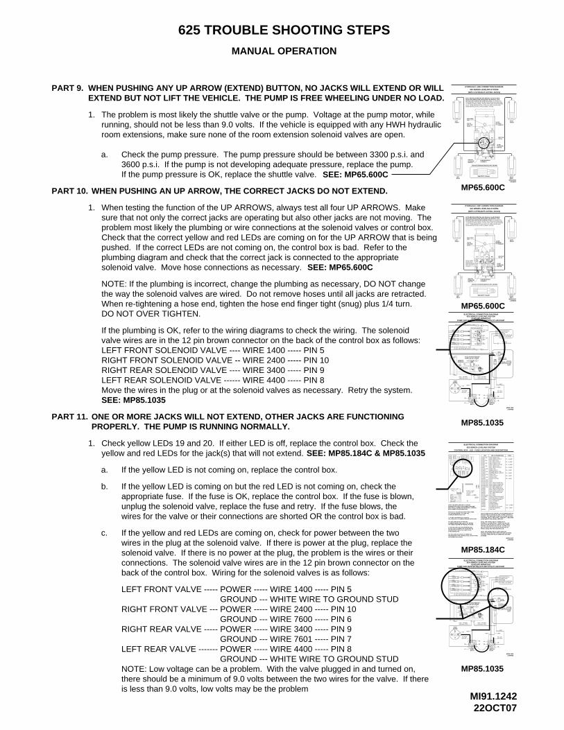
MI91.124222OCT07
625 TROUBLE SHOOTING STEPS
MANUAL OPERATION
PART 9.
1.
WHEN PUSHING ANY UP ARROW (EXTEND) BUTTON, NO JACKS WILL EXTEND OR WILLEXTEND BUT NOT LIFT THE VEHICLE. THE PUMP IS FREE WHEELING UNDER NO LOAD.
The problem is most likely the shuttle valve or the pump. Voltage at the pump motor, whilerunning, should not be less than 9.0 volts. If the vehicle is equipped with any HWH hydraulicroom extensions, make sure none of the room extension solenoid valves are open.
a. Check the pump pressure. The pump pressure should be between 3300 p.s.i. and3600 p.s.i. If the pump is not developing adequate pressure, replace the pump. If the pump pressure is OK, replace the shuttle valve.
PART 10. WHEN PUSHING AN UP ARROW, THE CORRECT JACKS DO NOT EXTEND.
1. When testing the function of the UP ARROWS, always test all four UP ARROWS. Make sure that not only the correct jacks are operating but also other jacks are not moving. The problem most likely the plumbing or wire connections at the solenoid valves or control box. Check that the correct yellow and red LEDs are coming on for the UP ARROW that is being pushed. If the correct LEDs are not coming on, the control box is bad. Refer to the plumbing diagram and check that the correct jack is connected to the appropriate solenoid valve. Move hose connections as necessary. SEE: MP65.600C
IS SHOWN WITH (2) LARGE VALVES THAT HAVE VALVE RELEASE
SOME MANIFOLDS WILL HAVE (4) SMALL VALVES.NUTS. SOME MANIFOLDS WILL HAVE (4) LARGE VALVES AND "T"-HANDLES AND (2) SMALL VALVES THAT HAVE VALVE RELEASE
(ROOM EXTENSION MANIFOLD NOT SHOWN)
VELOCITY VALVE
625 SERIES LEVELING SYSTEM
ASSEMBLYPUMP/MANIFOLD
(WITH 4 STRAIGHT-ACTING JACKS)
HYDRAULIC LINE CONNECTION DIAGRAM
RETRACTION IN OPERATOR’S INSTRUCTIONS.READ AND UNDERSTAND PROCEDURE FOR MANUAL JACK NOTE: BEFORE OPERATING ANY MANUAL VALVE RELEASE
REARLEFT
3000 PSIPRESSURE
WITH VELOCITYARE EQUIPPED
NOTE: SOME
SWITCH
VALVES
MANIFOLDS
LR LF
FRONTLEFT
BREATHER
NUTSRELEASEVALVE
CAP
RF RR
PRESSURE
VALVESHUTTLE
SWITCH
50 PSI
23FEB04MP65.600C
RIGHTREAR
"T" HANDLES
VALVERELEASE
THIS MANIFOLD
FRONTRIGHT
MP65.600C
NOTE: If the plumbing is incorrect, change the plumbing as necessary, DO NOT changethe way the solenoid valves are wired. Do not remove hoses until all jacks are retracted.When re-tightening a hose end, tighten the hose end finger tight (snug) plus 1/4 turn.DO NOT OVER TIGHTEN.
If the plumbing is OK, refer to the wiring diagrams to check the wiring. The solenoidvalve wires are in the 12 pin brown connector on the back of the control box as follows:LEFT FRONT SOLENOID VALVE ---- WIRE 1400 ----- PIN 5RIGHT FRONT SOLENOID VALVE -- WIRE 2400 ----- PIN 10RIGHT REAR SOLENOID VALVE ---- WIRE 3400 ----- PIN 9LEFT REAR SOLENOID VALVE ------ WIRE 4400 ----- PIN 8Move the wires in the plug or at the solenoid valves as necessary. Retry the system.
ONE OR MORE JACKS WILL NOT EXTEND, OTHER JACKS ARE FUNCTIONING PART 11.
SEE: MP85.1035
MP85.1035
MASTERRELAY
PUMPRELAY
MOTOR
#6
#7
#5
#4 #3
#1
MP85.103527APR05
BATTERY
#2
#8
PUMP AND MASTER RELAYS WITH PILOT AIR DUMP
625 SERIES LEVELING SYSTEMELECTRICAL CONNECTION DIAGRAM
NOTE: ROOM EXTENSIONMANIFOLD NOT SHOWN
TO 3000 LB PRESSURE SWITCH - 8100
HWH GROUND
GROUND STUD6231 - TO HWH
TO PUMP
#98600
LEVELING
TO HWH GROUND STUD - 6240
MANIFOLD
6230 - TO HWHGROUND STUD
8500
LR
LF
TO 50 LB PRESSURE SWITCH - 8101
LEVELING MANIFOLD
LEVELING MANIFOLD
RR
RF
12 PIN
6100
TO +12V
6800
GRAY
12 PINBROWN
4 PINGRAY
BLACK12 PIN
8 PINBLACK
GROUND STUDTO HWH
SEE ELECTRICALCONNECTIONDIAGRAM625 SERIES LEVELINGSYSTEM - AIR DUMP
9301
6230
9300
STUD
PUMPMOTOR
+
BA
BA
6240
62404400
1400
P.E
.DP
.E.D
BA
AB
34007601
76002400
P.E
.DP
.E.D
PROPERLY. THE PUMP IS RUNNING NORMALLY.
1. Check yellow LEDs 19 and 20. If either LED is off, replace the control box. Check the
a. If the yellow LED is not coming on, replace the control box.
b. If the yellow LED is coming on but the red LED is not coming on, check theappropriate fuse. If the fuse is OK, replace the control box. If the fuse is blown,unplug the solenoid valve, replace the fuse and retry. If the fuse blows, thewires for the valve or their connections are shorted OR the control box is bad.
SEE: MP85.184C & MP85.1035
c. If the yellow and red LEDs are coming on, check for power between the twowires in the plug at the solenoid valve. If there is power at the plug, replace thesolenoid valve. If there is no power at the plug, the problem is the wires or theirconnections. The solenoid valve wires are in the 12 pin brown connector on theback of the control box. Wiring for the solenoid valves is as follows:
LEFT FRONT VALVE ----- POWER ----- WIRE 1400 ----- PIN 5GROUND --- WHITE WIRE TO GROUND STUD
RIGHT FRONT VALVE --- POWER ----- WIRE 2400 ----- PIN 10GROUND --- WIRE 7600 ----- PIN 6
GROUND --- WIRE 7601 ----- PIN 7RIGHT REAR VALVE ----- POWER ----- WIRE 3400 ----- PIN 9
GROUND --- WHITE WIRE TO GROUND STUDLEFT REAR VALVE ------- POWER ----- WIRE 4400 ----- PIN 8
NOTE: Low voltage can be a problem. With the valve plugged in and turned on, there should be a minimum of 9.0 volts between the two wires for the valve. If there is less than 9.0 volts, low volts may be the problem
+12V
GROUNDLEFT SIDE
OR CONNECTION CABLE
4-PIN CONNECTOR.
PROBLEM WITH THE CONTROL BOX, TOUCH PANEL IF A YELLOW LED IS NOT LIT, THERE IS A
NO RED LED IS COMING ON THERE MAY BEPROBLEM WITH INPUT VOLTAGE IN THE
CORRESPONDING RELAY ON.
NOTE: A LIT YELLOW LED INDICATES THEREIS A GROUND SIGNAL TO TURN THE
A LIT RED LED INDICATES THERE IS VOLTAGE ON IT’S CORRESPONDING OUTPUT PIN.
CORRESPONDING RED LED IS OFF, EITHERIT’S FUSE IS BLOWN OR THE RELAY IS BAD.
IF THE YELLOW LED’S ARE WORKING BUT
IF A YELLOW LED IS LIT AND THE
BOX CONNECTION INFORMATION.ELECTRICAL CONNECTION DIAGRAM - CONTROLINFORMATION ABOUT PIN CONNECTIONS SEE NOTE: FOR DETAILED INPUT / OUTPUT
RE
AR
24
NOT USEDNOT USEDLEFT REAR PRESS SW
PARK BRAKEBOARD ENABLE
JACK INTERRUPT
RIGHT FRONT PRESS SWLEFT FRONT PRESS SW
RIGHT REAR PRESS SW
50 LB PRESS SW INPUTMASTER WARN CONTROL3000 LB PRESS SW INPUT
LINK LIGHTMASTER WARNINGACCESSORY OUT FORACCESSORY IN
IT IS ONLY USED WITH PILOT OPERATED AIR DUMPVEHICLES EQUIPPED WITH HWH AIR DUMP SYSTEMS.NOTE: THE TRAVEL RELAY IS NOT USED ON
TRAVEL MODE AND THE IGNITION IS ON.
LATER LED’S 3 AND 19 WILL TURN OFF.IS PUSHED, LED’s 7 AND 20 WILL TURN OFF. 5 SECONDSPUSHED. TWO SECONDS AFTER THE "STORE" BUTTONTOUCH PANEL IS ON UNLESS THE "STORE" BUTTON ISLED’S 19 AND 20 (YELLOW) WILL BE ON WHENEVER THE
WILL BE ON IF THE LEVELING SYSTEM IS IN THE
NOTE: THE TRAVEL RELAY IS WIRED AS A NORMALLY CLOSED RELAY. WHEN THE YELLOWLED (17) IS ON THE RELAY CONTACTS WILL OPEN.THE RED LED (18) WILL NOT BE ON. THE RED LED
MP85.184C
+12 ACC TOFUSE 7.5 AMP
SENSING UNIT
RIGHT SIDE
PIN 1
REAR
FRONT
39
26
25
28
27
TOUCHPANEL
SYSTEMS.
28-RED27-RED26-RED25-RED
29-RED
37-RED38-RED
39-RED
36-RED35-RED34-RED
32-RED33-GREEN
31-GREEN30-YELLOW
36
F12
3837
F10 - 10 AMP
27APR05MP85.184C
F11 - 3 AMP
ELECTRICAL CONNECTION DIAGRAM
RELAY DESCRIPTION
RIGHT REAR COIL
RIGHT FRONT COIL
LEFT FRONT COIL
PUMP COIL
DUMP COIL
PUMP OUTPUT
DUMP OUTPUTMASTER RELAY COIL
LEFT FRONT OUTPUT
CRX 2TRAVEL OUTPUTTRAVEL COIL
LEFT REAR COILLEFT REAR OUTPUT
RIGHT REAR OUTPUT
LEFT REAR WARN SW
CRX 1
RIGHT REAR WARN SWRIGHT FRONT WARN SWLEFT FRONT WARN SW
RIGHT FRONT OUTPUT
MASTER RELAY OUTPUT
CONTROL BOX - LED - FUSE LOCATION AND DESCRIPTION
625 SERIES LEVELING SYSTEM
DU
MP
RE
LAY
MA
ST
ER
F1
LED
4
3
2
1
FUSE
19
F2
1412
1311
F6
TR
AV
EL
RE
LAY
PU
MP
29
23
21
22323130 33
F3
F8
16
6
15
F7
5
F48
F9
17
18
7
20
LEF
TR
EA
R
RIG
HT
CR
X2
FR
ON
TR
IGH
T
FR
ON
TLE
FT
3-YELLOW
5-YELLOW6-RED
8-RED7-YELLOW
4-RED
20-YELLOW
23-YELLOW22-YELLOW21-YELLOW
24-YELLOW
F10
3534
F11
19-YELLOW
17-YELLOW
15-YELLOW
18-RED
16-RED
11-YELLOW
13-YELLOW12-RED
14-RED
2-RED
CR
X1
1-YELLOW
LED
F8 - 5 AMP
F9 - 5 AMP
F3 - 15 AMP
F7 - 5 AMP
F6 - 5 AMP
F4 - 15 AMP
F2 - 15 AMP
F1 - 15 AMP
FUSE
MP85.1035
MASTERRELAY
PUMPRELAY
MOTOR
#6
#7
#5
#4 #3
#1
MP85.103527APR05
BATTERY
#2
#8
PUMP AND MASTER RELAYS WITH PILOT AIR DUMP
625 SERIES LEVELING SYSTEMELECTRICAL CONNECTION DIAGRAM
NOTE: ROOM EXTENSIONMANIFOLD NOT SHOWN
TO 3000 LB PRESSURE SWITCH - 8100
STUDHWH GROUND
GROUND STUD6231 - TO HWH
PUMPMOTOR
+ TO PUMP
#98600
LEVELING
TO HWH GROUND STUD - 6240
MANIFOLD
BA
BA
6240
62404400
1400
P.E
.DP
.E.D
6230 - TO HWHGROUND STUD
8500
LR
LF
TO 50 LB PRESSURE SWITCH - 8101
LEVELING MANIFOLD
BA
AB
34007601
76002400
P.E
.DP
.E.D
LEVELING MANIFOLD
RR
RF
12 PIN
6100
TO +12V
6800
GRAY
12 PINBROWN
4 PINGRAY
BLACK12 PIN
8 PINBLACK
GROUND STUDTO HWH
SEE ELECTRICALCONNECTIONDIAGRAM625 SERIES LEVELINGSYSTEM - AIR DUMP
9301
6230
9300
SEE: MP65.600C(ROOM EXTENSION MANIFOLD NOT SHOWN)
MP65.600C
3000 PSIPRESSURESWITCH
REARLEFT
VELOCITY VALVE
ASSEMBLYPUMP/MANIFOLD
23FEB04MP65.600C
RIGHTREAR
PRESSURESWITCH
IS SHOWN WITH (2) LARGE VALVES THAT HAVE VALVE RELEASE
SOME MANIFOLDS WILL HAVE (4) SMALL VALVES.NUTS. SOME MANIFOLDS WILL HAVE (4) LARGE VALVES AND "T"-HANDLES AND (2) SMALL VALVES THAT HAVE VALVE RELEASE
625 SERIES LEVELING SYSTEM
(WITH 4 STRAIGHT-ACTING JACKS)
HYDRAULIC LINE CONNECTION DIAGRAM
RETRACTION IN OPERATOR’S INSTRUCTIONS.READ AND UNDERSTAND PROCEDURE FOR MANUAL JACK NOTE: BEFORE OPERATING ANY MANUAL VALVE RELEASE
RR
BREATHER
RELEASE
LEFTFRONT
CAP
NUTS
VALVE
LFLR RF
FRONTRIGHT
"T" HANDLES
SHUTTLEVALVE
50 PSI
VALVERELEASE
THIS MANIFOLD
yellow and red LEDs for the jack(s) that will not extend.
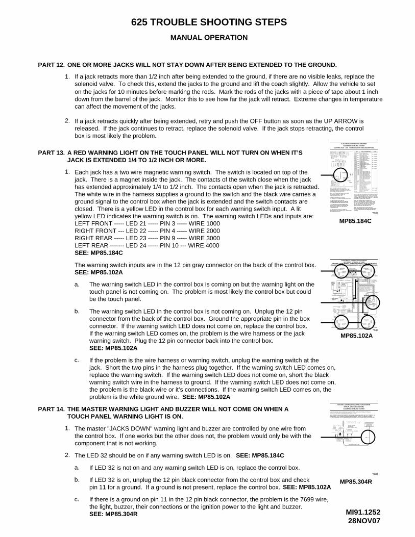
MI91.125228NOV07
625 TROUBLE SHOOTING STEPS
MANUAL OPERATION
PART 12.
MP85.184C
RIG
HT
NOTE: FOR DETAILED INPUT / OUTPUT INFORMATION ABOUT PIN CONNECTIONS SEE ELECTRICAL CONNECTION DIAGRAM - CONTROLBOX CONNECTION INFORMATION.
IF A YELLOW LED IS LIT AND THE
IF THE YELLOW LED’S ARE WORKING BUT
IT’S FUSE IS BLOWN OR THE RELAY IS BAD.CORRESPONDING RED LED IS OFF, EITHER
VOLTAGE ON IT’S CORRESPONDING OUTPUT PIN.A LIT RED LED INDICATES THERE IS
IS A GROUND SIGNAL TO TURN THE NOTE: A LIT YELLOW LED INDICATES THERE
CORRESPONDING RELAY ON.
PROBLEM WITH INPUT VOLTAGE IN THE NO RED LED IS COMING ON THERE MAY BE
IF A YELLOW LED IS NOT LIT, THERE IS A PROBLEM WITH THE CONTROL BOX, TOUCH PANEL
4-PIN CONNECTOR.
OR CONNECTION CABLE
LEFT SIDEGROUND
RIGHT SIDE
SENSING UNIT
+12V
FRONT
REAR
FUSE
1
2
RE
AR
625 SERIES LEVELING SYSTEM
CONTROL BOX - LED - FUSE LOCATION AND DESCRIPTION
THE RED LED (18) WILL NOT BE ON. THE RED LEDLED (17) IS ON THE RELAY CONTACTS WILL OPEN.NORMALLY CLOSED RELAY. WHEN THE YELLOWNOTE: THE TRAVEL RELAY IS WIRED AS A
WILL BE ON IF THE LEVELING SYSTEM IS IN THE
LED’S 19 AND 20 (YELLOW) WILL BE ON WHENEVER THETOUCH PANEL IS ON UNLESS THE "STORE" BUTTON ISPUSHED. TWO SECONDS AFTER THE "STORE" BUTTONIS PUSHED, LED’s 7 AND 20 WILL TURN OFF. 5 SECONDSLATER LED’S 3 AND 19 WILL TURN OFF.
TRAVEL MODE AND THE IGNITION IS ON.
NOTE: THE TRAVEL RELAY IS NOT USED ONVEHICLES EQUIPPED WITH HWH AIR DUMP SYSTEMS.IT IS ONLY USED WITH PILOT OPERATED AIR DUMP
ACCESSORY INACCESSORY OUT FORMASTER WARNINGLINK LIGHT
MASTER RELAY OUTPUT
RIGHT FRONT OUTPUT
LEFT FRONT WARN SWRIGHT FRONT WARN SWRIGHT REAR WARN SW
3000 LB PRESS SW INPUTMASTER WARN CONTROL50 LB PRESS SW INPUT
RIGHT REAR PRESS SW
LEFT FRONT PRESS SWRIGHT FRONT PRESS SW
CRX 1
JACK INTERRUPT
BOARD ENABLEPARK BRAKE
LEFT REAR PRESS SWNOT USEDNOT USED
LEFT REAR WARN SW
RIGHT REAR OUTPUT
LEFT REAR OUTPUTLEFT REAR COIL
TRAVEL COILTRAVEL OUTPUTCRX 2
LEFT FRONT OUTPUT
MASTER RELAY COILDUMP OUTPUT
PUMP OUTPUT
DUMP COIL
PUMP COIL
LEFT FRONT COIL
RIGHT FRONT COIL
RIGHT REAR COIL
30-YELLOWF12PANEL
39
SYSTEMS.
3736 3831-GREEN
33-GREEN32-RED
34-RED35-RED36-RED
39-RED
38-RED37-RED
FUSE 7.5 AMP
33
+12 ACC TOTOUCH
20
PU
MP
RE
LAY
TR
AV
EL
MA
ST
ER
RE
LAY
DU
MP
PIN 1
22
21
27
28
25
26
24
23
29 30 31 32
3
4
LED
F1
F6
11 13
12 14
F2 19
LEF
T
CR
X2
RE
AR
5
F7 15
6
16
7
F8 18
17
F9
8
F3
F4
LEF
TF
RO
NT
RIG
HT
FR
ON
T
13-YELLOW
34 35
F10
F11
15-YELLOW
17-YELLOW
19-YELLOW
14-RED
16-RED
18-RED
24-YELLOW
29-RED
25-RED26-RED27-RED28-RED
21-YELLOW22-YELLOW23-YELLOW
20-YELLOW
CR
X1
LED
3-YELLOW2-RED
4-RED
7-YELLOW
11-YELLOW8-RED
12-RED
6-RED5-YELLOW
1-YELLOW
MP85.184C27APR05
F11 - 3 AMP
F10 - 10 AMP
FUSE
F1 - 15 AMP
F2 - 15 AMP
F9 - 5 AMP
F4 - 15 AMP
F6 - 5 AMP
F7 - 5 AMP
F8 - 5 AMP
F3 - 15 AMP
RELAY DESCRIPTION
ELECTRICAL CONNECTION DIAGRAM
ONE OR MORE JACKS WILL NOT STAY DOWN AFTER BEING EXTENDED TO THE GROUND.
SEE: MP85.184C
touch panel is not coming on. The problem is most likely the control box but could The warning switch LED in the control box is coming on but the warning light on thea.
PART 13. A RED WARNING LIGHT ON THE TOUCH PANEL WILL NOT TURN ON WHEN IT’SJACK IS EXTENDED 1/4 TO 1/2 INCH OR MORE.
1. Each jack has a two wire magnetic warning switch. The switch is located on top of thejack. There is a magnet inside the jack. The contacts of the switch close when the jackhas extended approximately 1/4 to 1/2 inch. The contacts open when the jack is retracted.The white wire in the harness supplies a ground to the switch and the black wire carries aground signal to the control box when the jack is extended and the switch contacts are closed. There is a yellow LED in the control box for each warning switch input. A lit yellow LED indicates the warning switch is on. The warning switch LEDs and inputs are:LEFT FRONT ----- LED 21 ----- PIN 3 ----- WIRE 1000RIGHT FRONT --- LED 22 ----- PIN 4 ----- WIRE 2000RIGHT REAR ----- LED 23 ----- PIN 9 ----- WIRE 3000LEFT REAR ------- LED 24 ----- PIN 10 --- WIRE 4000
The warning switch inputs are in the 12 pin gray connector on the back of the control box.
be the touch panel.
b.
SEE: MP85.102A
The warning switch LED in the control box is not coming on. Unplug the 12 pinconnector from the back of the control box. Ground the appropriate pin in the boxconnector. If the warning switch LED does not come on, replace the control box.If the warning switch LED comes on, the problem is the wire harness or the jackwarning switch. Plug the 12 pin connector back into the control box.
c. If the problem is the wire harness or warning switch, unplug the warning switch at thejack. Short the two pins in the harness plug together. If the warning switch LED comes on,replace the warning switch. If the warning switch LED does not come on, short the blackwarning switch wire in the harness to ground. If the warning switch LED does not come on,the problem is the black wire or it’s connections. If the warning switch LED comes on, theproblem is the white ground wire.
SEE: MP85.102A
SEE: MP85.102A
MASTERWARNING
LEFT FRONT
LIGHT
SWITCH
LEFT REAR
PARK BRAKE
TOUCH PANEL - JACK WARNING LIGHTS AND PRESSURE SWITCHESAIR DUMP - PARK BRAKE - MASTER WARNING LIGHT AND BUZZER
MP85.102A
WARNING
DIAGRAM - 625 SERIES
MANIFOLD - PUMP AND MASTER RELAYS
6230 - 6231
SWITCH
SEE ELECTRICAL CONNECTION
LEVELING SYSTEM - LEVELING
SWITCHWARNING
LIGHT
93009301
62306231
WARNING
4000
AB
4200
SWITCH
6235
PILOT AIR DUMPCONNECTION
SWITCHPRESSURE
93019300
62306231
STUD
TO HWHGROUND
AB
C
TO IGNITION
TO ACCESSORY
9001 - TOPARK BRAKE
6111
7699
DIODE
DIODE
5AMP
6111
7699
7699
9000
BUZZER
+ _
SWITCHPRESSURE
1000
6110
AB
1200
FUSE
SWITCH
6235
WARNING
90007699
6120
UNDERSTAND OPERATOR’S MANUAL BEFORE USING. BLOCK FRAME AND TIRES
DUMPSTORE
CAUTION!
SECURELY BEFORE REMOVING TIRES OR CRAWLING UNDER VEHICLE.
MODEOFF
TRAVEL
HWH COMPUTERIZED LEVELING
TOUCH PANEL
PARK/
LEVEL SLOPEEXCESS
NOT IN
HYD
BRAKE
GRAY
62353000
AB
3200
RIGHT REAR
MP85.102A16FEB05
BLACK8 PIN
PRESSURESWITCH
12 PINGRAY
12 PINBLACK4 PIN
BROWN12 PIN
12 PINGREEN
62352000
93019300
AB
2200
PRESSURESWITCH
RIGHT FRONT
PILOT DUMPCONNECTIONBY OEM
ELECTRICAL CONNECTION DIAGRAM625 SERIES LEVELING SYSTEM
THE MASTER WARNING LIGHT AND BUZZER WILL NOT COME ON WHEN A TOUCH PANEL WARNING LIGHT IS ON.
PART 14.
1. The master "JACKS DOWN" warning light and buzzer are controlled by one wire fromthe control box. If one works but the other does not, the problem would only be with thecomponent that is not working.
2. The LED 32 should be on if any warning switch LED is on.
a. If LED 32 is not on and any warning switch LED is on, replace the control box.
b. If LED 32 is on, unplug the 12 pin black connector from the control box and check pin 11 for a ground. If a ground is not present, replace the control box.
c. If there is a ground on pin 11 in the 12 pin black connector, the problem is the 7699 wire,the light, buzzer, their connections or the ignition power to the light and buzzer.
SEE: MP85.184C
SEE: MP85.102A
SEE: MP85.304R
MP85.304R
BUZZERCONTROL
CONNECT THIS END TO+12 VOLT IGNITION "ON" POWER
MASTER LIGHT/BUZZER CONNECTION DIAGRAMMANUAL LEVELING SYSTEMS
625 SERIES LEVELING SYSTEM
A MASTER WARNING INDICATOR SHOULD ALWAYS BE USED. WHEN THE LEVELING SYSTEM HAS STRAIGHT-ACTING JACKS A WARNING BUZZER MUST BE USED.
NOTE: BY SUPPLYING IGNITION POWER TO THE WARNING BUZZER AND LIGHT, AND "ACC" POWER TO THE CONTROL BOX, THE SYSTEM MAY BE OPERATED IN ACCESSORY WITHOUT THE BUZZER SOUNDING. THE NEGATIVE SIGNAL FOR THE WARNING INDICATORS MUST ALWAYS COME FROM THE CONTROL BOX.
WARN LIGHTCONTROL
6111
5-15 AMP FUSE
DOWNLIGHT
7699
JACK
6111
IGN
ITIO
N
MP85.304R13MAY04
PIGTAIL PROVIDED - 7699
BUZZER
PIGTAIL W/DIODE
FUSE HOLDER - 6121
7699
+ _
AND IN-LINE
SEE CONTROL BOXCONNECTION INFORMATION
7699
down from the barrel of the jack. Monitor this to see how far the jack will retract. Extreme changes in temperatureon the jacks for 10 minutes before marking the rods. Mark the rods of the jacks with a piece of tape about 1 inch
released. If the jack continues to retract, replace the solenoid valve. If the jack stops retracting, the control If a jack retracts quickly after being extended, retry and push the OFF button as soon as the UP ARROW is
solenoid valve. To check this, extend the jacks to the ground and lift the coach slightly. Allow the vehicle to set If a jack retracts more than 1/2 inch after being extended to the ground, if there are no visible leaks, replace the
box is most likely the problem.
can affect the movement of the jacks.
2.
1.

MI91.126215MAY08
625 TROUBLE SHOOTING STEPS
MANUAL OPERATION
PART 15. BUTTON IS PUSHED. SOME JACKS WILL RETRACT.
1.
If the jack will not retract, the problem is the hose, velocity valve (if so equipped) a.
LATER LED’S 3 AND 19 WILL TURN OFF.IS PUSHED, LED’s 7 AND 20 WILL TURN OFF. 5 SECONDSPUSHED. TWO SECONDS AFTER THE "STORE" BUTTONTOUCH PANEL IS ON UNLESS THE "STORE" BUTTON ISLED’S 19 AND 20 (YELLOW) WILL BE ON WHENEVER THE
SYSTEMS.IT IS ONLY USED WITH PILOT OPERATED AIR DUMPVEHICLES EQUIPPED WITH HWH AIR DUMP SYSTEMS.NOTE: THE TRAVEL RELAY IS NOT USED ON
TRAVEL MODE AND THE IGNITION IS ON.WILL BE ON IF THE LEVELING SYSTEM IS IN THE
NOTE: THE TRAVEL RELAY IS WIRED AS A NORMALLY CLOSED RELAY. WHEN THE YELLOWLED (17) IS ON THE RELAY CONTACTS WILL OPEN.THE RED LED (18) WILL NOT BE ON. THE RED LED
CONTROL BOX - LED - FUSE LOCATION AND DESCRIPTION
625 SERIES LEVELING SYSTEM
ELECTRICAL CONNECTION DIAGRAM
OR CONNECTION CABLEPROBLEM WITH THE CONTROL BOX, TOUCH PANEL
NOTE: A LIT YELLOW LED INDICATES THEREIS A GROUND SIGNAL TO TURN THE CORRESPONDING RELAY ON.
A LIT RED LED INDICATES THERE IS VOLTAGE ON IT’S CORRESPONDING OUTPUT PIN.
CORRESPONDING RED LED IS OFF, EITHERIT’S FUSE IS BLOWN OR THE RELAY IS BAD.
IF THE YELLOW LED’S ARE WORKING BUTNO RED LED IS COMING ON THERE MAY BEPROBLEM WITH INPUT VOLTAGE IN THE 4-PIN CONNECTOR.
IF A YELLOW LED IS NOT LIT, THERE IS A
IF A YELLOW LED IS LIT AND THE
BOX CONNECTION INFORMATION.ELECTRICAL CONNECTION DIAGRAM - CONTROLINFORMATION ABOUT PIN CONNECTIONS SEE NOTE: FOR DETAILED INPUT / OUTPUT
+12VREAR
FRONT
GROUND
RIGHT SIDE
LEFT SIDE
PANELTOUCH+12 ACC TO28
39
F12
383736
SENSING UNIT
31
PIN 1
FUSE
LED
2
DU
MP
4
F1
12
11
F2
RE
AR
RIG
HT
RE
AR
LEF
T
75
FUSE 7.5 AMP
32
F4
F9
21
26
27
25
24
23
22313029
15
16
F7
MA
ST
ER
RE
LAY
RE
LAY
F6
14
13
196
F8
PU
MP
TR
AV
EL
17
F3
18
8
353433
F10
F11
20
RIG
HT
CR
X2
FR
ON
T
FR
ON
TLE
FT
CR
X1
RIGHT REAR PRESS SW
MASTER WARNINGLINK LIGHT
ACCESSORY OUT FORACCESSORY INBOARD ENABLEPARK BRAKEJACK INTERRUPT50 LB PRESS SW INPUTMASTER WARN CONTROL3000 LB PRESS SW INPUTNOT USEDNOT USEDLEFT REAR PRESS SW
38-RED
39-RED
33-GREEN
31-GREEN30-YELLOW
37-RED36-RED35-RED34-RED
32-RED
29-RED28-RED
MP85.184C
F11 - 3 AMP
F10 - 10 AMP
RIGHT FRONT PRESS SWLEFT FRONT PRESS SWLEFT REAR WARN SWRIGHT REAR WARN SWRIGHT FRONT WARN SWLEFT FRONT WARN SW
CRX 2TRAVEL OUTPUTTRAVEL COILPUMP OUTPUTPUMP COILMASTER RELAY OUTPUTMASTER RELAY COILDUMP OUTPUTDUMP COILLEFT FRONT OUTPUTLEFT FRONT COILRIGHT FRONT OUTPUTRIGHT FRONT COILLEFT REAR OUTPUT
24-YELLOW23-YELLOW22-YELLOW21-YELLOW20-YELLOW19-YELLOW
17-YELLOW
27-RED26-RED25-RED
18-RED
CRX 1
15-YELLOW
13-YELLOW
11-YELLOW
7-YELLOW
5-YELLOW
16-RED
14-RED
12-RED
8-RED
6-RED
4-REDLEFT REAR COILRIGHT REAR OUTPUTRIGHT REAR COIL
RELAY DESCRIPTION
3-YELLOW
1-YELLOW2-RED
LED
F9 - 5 AMP
F8 - 5 AMP
F7 - 5 AMP
F6 - 5 AMP
F4 - 15 AMP
F3 - 15 AMP
F2 - 15 AMP
F1 - 15 AMP
FUSE
27APR05
MP85.184C
ONE OR MORE JACKS WILL NOT RETRACT WHEN A DOWN ARROW (RETRACT)
The pump should not run when a DOWN ARROW is pushed. If a pump runs whena DOWN ARROW is pushed, the control box or touch panel is the problem.
2. Open the valve release nut (small valve) 4 1/2 complete turns or the valve releaseT-handle (large valve) approximately 5 full turns counter-clockwise.
or the jack. Slowly remove the hose from the jack. If the jack does not retract,replace the jack. If the jack starts to retract, tighten the hose and loosen the hoseat the manifold. If the jack does not retract, there is a problem with the hose, suchas a kink. If the jack retracts and the manifold is equipped with a velocity valve,the valve is most likely the problem. If there is no velocity valve, there may be acheck valve or solenoid valve problem. Contact HWH technical service.
3. If the jack retracts when the valve is manually opened, the control box is most likely theproblem. If the jack will extend, the valve and it’s connection to the control box shouldbe OK.
a. Check the yellow and red LEDs for the jack that is not retracting. If the yellow LEDis not coming on while the down arrow is being pushed, replace the control box.If the yellow LED is coming on, review PART 11, 1b and 1c. If a jack will extend,the solenoid valve and wiring should be OK when pushing a DOWN ARROW also.REMEMBER LOW VOLTAGE WILL CAUSE PROBLEMS.
CAUTION: DO NOT CRAWL UNDER ANY VEHICLE SUPPORTED ON THE LEVELINGJACKS WITHOUT PROPERLY SUPPORTING THE FRAME OF THE VEHICLESO IT CANNOT DROP WHEN THE FLUID IS RELEASED FROM A JACK.
PART 16. NO JACKS WILL RETRACT WHEN PUSHING ANY OF THE DOWN ARROW (RETRACT) BUTTONS.
1. Check the yellow and red LEDs for the solenoid valves while pushing the DOWN ARROW buttons. If the yellow LEDs are not coming on, the problem is the control box or touch panel. If the red LEDs are not coming on, the master relay mayhave a problem, refer to PART 7. If the yellow and red LEDs are coming on, theproblem is most likely the shuttle valve. Turn the valve release nuts (small valves)4 1/2 complete turns (no more) or valve release T-handles (large valves) 5 full turnscounterclockwise. If the jacks retract, the problem is the solenoid valves or their connections. If the jacks do not retract, replace the shuttle valve. IMPORTANT:Do not remove the shuttle valve until all solenoid valves are closed, electrically ormanually.
NOTE: Remember yellow LEDs 19 and 20 should be on whenever the touch panel is on except duringthe automatic retract mode. If LED 19 is not on, the right rear solenoid valve will not function.If LED 20 is not on, the right front solenoid valve will not function. If either LED 19 or 20 is noton, replace the control box.
MP65.600C
RR
(ROOM EXTENSION MANIFOLD NOT SHOWN)
MANIFOLDS
SWITCH
NOTE: SOME
ARE EQUIPPEDWITH VELOCITY
PRESSURE3000 PSI
LEFTREAR
VALVES
VELOCITY VALVE
LF
PUMP/MANIFOLDASSEMBLY
LR RF
REARRIGHT
MP65.600C23FEB04
SHUTTLE
PRESSURE50 PSI
SWITCH
VALVE
NOTE: BEFORE OPERATING ANY MANUAL VALVE RELEASEREAD AND UNDERSTAND PROCEDURE FOR MANUAL JACK RETRACTION IN OPERATOR’S INSTRUCTIONS.
HYDRAULIC LINE CONNECTION DIAGRAM
(WITH 4 STRAIGHT-ACTING JACKS)
625 SERIES LEVELING SYSTEM
"T"-HANDLES AND (2) SMALL VALVES THAT HAVE VALVE RELEASENUTS. SOME MANIFOLDS WILL HAVE (4) LARGE VALVES AND SOME MANIFOLDS WILL HAVE (4) SMALL VALVES.
IS SHOWN WITH (2) LARGE VALVES THAT HAVE VALVE RELEASE
RELEASE
BREATHER
FRONTLEFT
VALVE
NUTS
CAPRIGHTFRONT
"T" HANDLESRELEASEVALVE
THIS MANIFOLD
SEE: MP85.600C
SEE: MP85.600C
SEE: MP85.184C
SEE: MP85.184C & MP65.600C
SEE: MP85.184C
THE RED WARNING LIGHT FOR A JACK WILL NOT GO OUT WHEN THE JACK IS FULLY RETRACTED.PART 17.
Check the yellow LED for the proper warning switch input in the control box. Number 21 is for the1.left front jack, 22 is for the right front jack, 23 is for the right rear jack and 24 is for the left rear jack.If the warning switch LED is not on, replace the control box.
2. If a warning switch LED is on, unplug the warning switch for the jack(s) that have a litLED. If the LED(s) go out, the problem is the warning switch. NOTE: The magnet inthe jack may be bad. If a new switch does not fix the problem, contact HWH customerservice. If the LED stays on with the warning switch unplugged, unplug the 12 pin grayconnector from the back of the control box. If the LED remains on, replace the controlbox. If the LED goes out, the warning switch wire(s) for the LED(s) that are on areshorted to ground.
SEE: MP85.184C
MASTERWARNING
LEFT FRONT
LIGHT
SWITCH
LEFT REAR
PARK BRAKE
TOUCH PANEL - JACK WARNING LIGHTS AND PRESSURE SWITCHESAIR DUMP - PARK BRAKE - MASTER WARNING LIGHT AND BUZZER
MP85.102A
WARNING
DIAGRAM - 625 SERIES
MANIFOLD - PUMP AND MASTER RELAYS
6230 - 6231
SWITCH
SEE ELECTRICAL CONNECTION
LEVELING SYSTEM - LEVELING
SWITCHWARNING
LIGHT
93009301
62306231
WARNING
4000
AB
4200
SWITCH
6235
PILOT AIR DUMPCONNECTION
SWITCHPRESSURE
93019300
62306231
STUD
TO HWHGROUND
AB
C
TO IGNITION
TO ACCESSORY
9001 - TOPARK BRAKE
6111
7699
DIODE
DIODE
5AMP
6111
7699
7699
9000
BUZZER
+ _
SWITCHPRESSURE
1000
6110
AB
1200
FUSE
SWITCH
6235
WARNING
90007699
6120
UNDERSTAND OPERATOR’S MANUAL BEFORE USING. BLOCK FRAME AND TIRES
DUMPSTORE
CAUTION!
SECURELY BEFORE REMOVING TIRES OR CRAWLING UNDER VEHICLE.
MODEOFF
TRAVEL
HWH COMPUTERIZED LEVELING
TOUCH PANEL
PARK/
LEVEL SLOPEEXCESS
NOT IN
HYD
BRAKE
GRAY
62353000
AB
3200
RIGHT REAR
MP85.102A16FEB05
BLACK8 PIN
PRESSURESWITCH
12 PINGRAY
12 PINBLACK4 PIN
BROWN12 PIN
12 PINGREEN
62352000
93019300
AB
2200
PRESSURESWITCH
RIGHT FRONT
PILOT DUMPCONNECTIONBY OEM
ELECTRICAL CONNECTION DIAGRAM625 SERIES LEVELING SYSTEM
SEE: MP85.102A
pins of the Packard connectors. The black wires must be in the "B" pins of NOTE: Make sure the white wires of the harness and warning switch are in the "A"
the connectors.
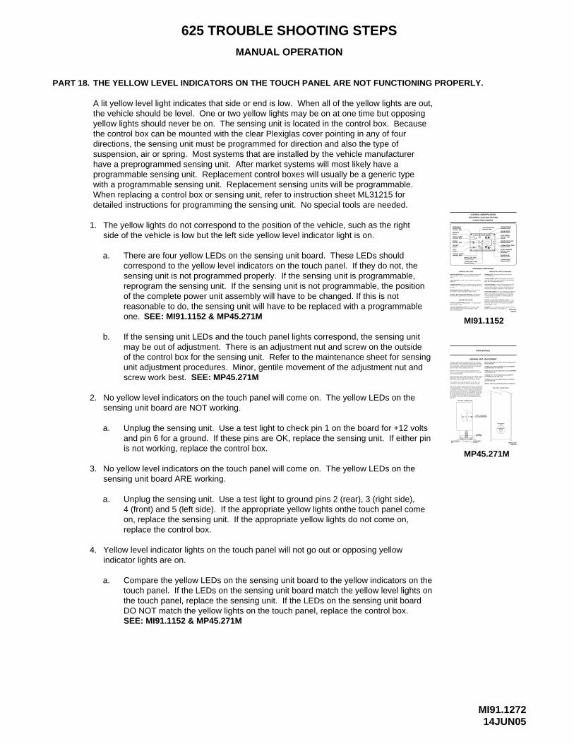
MI91.127214JUN05
625 TROUBLE SHOOTING STEPS
MANUAL OPERATION
PART 18.
1.
a.
THE YELLOW LEVEL INDICATORS ON THE TOUCH PANEL ARE NOT FUNCTIONING PROPERLY.
A lit yellow level light indicates that side or end is low. When all of the yellow lights are out,the vehicle should be level. One or two yellow lights may be on at one time but opposingyellow lights should never be on. The sensing unit is located in the control box. Becausethe control box can be mounted with the clear Plexiglas cover pointing in any of fourdirections, the sensing unit must be programmed for direction and also the type of suspension, air or spring. Most systems that are installed by the vehicle manufacturerhave a preprogrammed sensing unit. After market systems will most likely have a programmable sensing unit. Replacement control boxes will usually be a generic typewith a programmable sensing unit. Replacement sensing units will be programmable.When replacing a control box or sensing unit, refer to instruction sheet ML31215 fordetailed instructions for programming the sensing unit. No special tools are needed.
The yellow lights do not correspond to the position of the vehicle, such as the rightside of the vehicle is low but the left side yellow level indicator light is on.
There are four yellow LEDs on the sensing unit board. These LEDs shouldcorrespond to the yellow level indicators on the touch panel. If they do not, thesensing unit is not programmed properly. If the sensing unit is programmable,reprogram the sensing unit. If the sensing unit is not programmable, the positionof the complete power unit assembly will have to be changed. If this is not reasonable to do, the sensing unit will have to be replaced with a programmableone.
b. If the sensing unit LEDs and the touch panel lights correspond, the sensing unitmay be out of adjustment. There is an adjustment nut and screw on the outsideof the control box for the sensing unit. Refer to the maintenance sheet for sensingunit adjustment procedures. Minor, gentile movement of the adjustment nut andscrew work best.
2. No yellow level indicators on the touch panel will come on. The yellow LEDs on the sensing unit board are NOT working.
a. Unplug the sensing unit. Use a test light to check pin 1 on the board for +12 voltsand pin 6 for a ground. If these pins are OK, replace the sensing unit. If either pinis not working, replace the control box.
3. No yellow level indicators on the touch panel will come on. The yellow LEDs on the sensing unit board ARE working.
a. Unplug the sensing unit. Use a test light to ground pins 2 (rear), 3 (right side),4 (front) and 5 (left side). If the appropriate yellow lights onthe touch panel come on, replace the sensing unit. If the appropriate yellow lights do not come on,replace the control box.
4. Yellow level indicator lights on the touch panel will not go out or opposing yellowindicator lights are on.
a. Compare the yellow LEDs on the sensing unit board to the yellow indicators on thetouch panel. If the LEDs on the sensing unit board match the yellow level lights on the touch panel, replace the sensing unit. If the LEDs on the sensing unit board DO NOT match the yellow lights on the touch panel, replace the control box.
"EXCESS SLOPE"Indicator light
CAUTION!
SECURELY BEFORE REMOVING TIRES OR CRAWLING UNDER VEHICLE.UNDERSTAND OPERATOR’S MANUAL BEFORE USING. BLOCK FRAME AND TIRES
HWH COMPUTERIZED LEVELING
COMPUTER-CONTROL
625 SERIES LEVELING SYSTEM
CONTROL IDENTIFICATION
CONTROL FUNCTIONS
LOWER LEFT SIDE
that the panel is active.HYDRAULIC OPERATIONS (I) LIGHT:
button is being pushed.
operation button. The on indicator light is above the (I)
will retract their respective jack pairs to lower the vehicle.
extend their respective jack pairs to lift the vehicle.
RETRACT BUTTONS (DOWN ARROWS):
EXTEND BUTTONS (UP ARROWS):
CONTROL BUTTONS
INDICATOR LIGHTS
when the hand/auto brake is not set and the "LEVEL""NOT IN PARK/BRAKE" LIGHT:
"STORE" button. This button is used to automatically retract"STORE" BUTTON:
ON/AUTO (I) BUTTON:
button.
the jacks.
operation."OFF" BUTTON:
This indicator will light
This light indicates
These buttons
Manual button
This is the on button and automatic
These buttons will
The store indicator light is above the
Push the "OFF" button to stop hydraulic
"NOT IN PARK"Indicator light
OPERATIONIndicator light
"TRAVEL MODE"Indicator light
Indicator light
HYDRAULIC
Button
"OFF"Button
Button
"STORE"
ON/AUTO
STORE
RAISE LEFT SIDEManual button
TRAVEL
OFFMODE
STORE
AUTOON
R
PARK/BRAKE
NOT IN
SLOPEEXCESS
This light indicates that the system
INDICATOR LIGHTS (Continued)
It will be on when any one or more jacks are extended
or "ACC" position, the system is on, and the jacks are
master "JACKS DOWN" warning light is on.
They are functional only when the ignition is in the "ON" yellow level indicators are jacks down WARNING lights.
The four red lights surrounding the
No more than two lights should be on at the same time.indicates that its side, end, or corner of the vehicle is low. level sensing indicators. When a yellow light is on, it
The four yellow indicating lights are
This is a jacks down warning. It will sound if the
This indicator light will be on
light mounted in the dash separate from the touch panel. MASTER "JACKS DOWN" WARNING LIGHT:
when the ignition is on, when the jacks are retracted and
extended 1/4 to 1/2 inch.
and the ignition is "ON".
BUZZER:
LEVELING LIGHTS:
there are no red WARNING lights on.
"TRAVEL MODE" LIGHT:
JACK DOWN LIGHTS:
is in STORE mode.STORE LIGHT:
17DEC02MP25.6010
This is a
LOWER FRONTManual button
RAISE FRONTManual button
JACK DOWNIndicator light
RAISE RIGHT SIDEManual button
LOWER RIGHT SIDEManual button
LEVEL SENSINGIndicator light (4) yellow
RAISE REARManual button
LOWER REARManual button
(4) red
SEE: MI91.1152 & MP45.271M MI91.1152
MAY BE DIFFERENTLED’S - LOCATION
SENSING UNIT ADJUSTMENT
MAINTENANCE
be a problem with the Sensing Unit or the mounting of the Control Box. If two LED’s are on, either adjustment may be
TOP VIEW - SENSING UNIT
NUTADJUSTMENT
made first.
SCREW
BOX WALLCONTROL
ADJUSTMENT
BD
C
A
be turned more than 1/4 turn to turn the LED out, there may to be turned more than 1/2 flat or the adjustment screw has to screw will turn out LED’s A and C. If the adjustment nut has the adjustment nut to turn out LED’s B and D. The adjustment to the drawing below. The Sensing Unit is adjusted by turning There are four LED’s on the Sensing Unit, A,B,C and D. Refer
Control Box is mounted to the power unit/valve assembly.The Sensing Unit is mounted inside the Control Box. The
socket w/driver and a philips screw driver will be needed.adjustments to the Sensing Unit are needed. A 7/8" or 3/4"If there are yellow LEVEL lights lit on the Touch Panel, manual
unit is properly adjusted.there are no yellow lights lit on the Touch Panel, the sensingWhen the vehicle is level according to the bubble level, if
level the vehicle until the bubble is centered.level, ignoring the yellow LEVEL lights on the Touch Panel,that is to be level. Using the Leveling System and the bubblethe freezer floor or upon whichever surface within the vehicleLevel the vehicle by placing a bubble level in the center of
ADJUSTMENTSCREW
NUTADJUSTMENT
MP45.271M12APR04
When all 4 LED’s are off, the Sensing Unit is adjusted.
SIDE VIEW - CONTROL BOX
If LED (D) is lit: Turn the adjustment nut CLOCKWISE
If LED (B) is lit: Turn the adjustment nut COUNTER
If LED (C) is lit: Turn the adjustment screw CLOCKWISE
If LED (A) is lit: Turn the adjustment screw COUNTER
NOTE: If opposing LED’s are lit, there is a problem withthe Sensing Unit.
until the LED is off.
CLOCKWISE until the LED is off.
until the LED is off.
CLOCKWISE until the LED is off.
MP45.271M
SEE: MP45.271M
SEE: MI91.1152 & MP45.271M
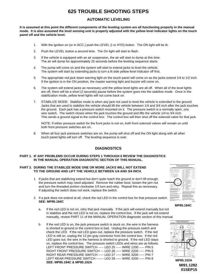
MI91.128201SEP15
625 TROUBLE SHOOTING STEPS
AUTOMATIC LEVELING
It is assumed at this point the different components of the leveling system are all functioning properly in the manual mode. It is also assumed the level sensing unit is properly adjusted with the yellow level indicator lights on the touchpanel off and the vehicle level.
1. With the ignition on (or in ACC.) push the LEVEL (I or HYD) button. The ON light will be lit.
2. Push the LEVEL button a second time. The On light will start to flash.
3. If the vehicle is equipped with an air suspension, the air will start to dump at this time.The air will dump for approximately 25 seconds before the leveling sequence starts.
4. The pump will come on and the system will start to extend jacks to level the vehicle.The system will start by extending jacks to turn a lit side yellow level indicator off first.
5. The appropriate red jack down warning light on the touch panel will come on as the jacks extend 1/4 to 1/2 inch.If the ignition is in the ON position, the master warning light and buzzer will come on.
6. The system will extend jacks as necessary until the yellow level lights are all off. When all of the level lights are off, there will be a short (2 seconds) pause before the system goes into the stabilize mode. Once in the stabilization mode, yellow level lights will not come back on.
7. STABILIZE MODE: Stabilize mode is when any jack not used to level the vehicle is extended to the ground. Jacks that are used to stabilize the vehicle should lift the vehicle between 1/4 and 3/4 inch after the jack touchesthe ground. Each jack has a pressure switch mounted on it. The pressure switch is a normally open, one wire switch. The switch closes when the jack touches the ground and lifts the vehicle 1/4 to 3/4 inch.
NOTE: If either pressure switch for the front jacks is not on, both front solenoid valves will remain on until both front pressure switches are on.
8. When all four jack pressure switches are on, the pump will shut off and the ON light along with all other touch panel lights will turn off. The leveling sequence is over.
This sends a ground signal to the control box. The control box will then shut off the solenoid valve for that jack.
DIAGNOSTICS
PART 1.
1.
a.
IF ANY PROBLEMS OCCUR DURING STEPS 1 THROUGH 6 REVIEW THE DIAGNOSTICSIN THE MANUAL OPERATION DIAGNOSTIC SECTION OF THIS MANUAL.
If jacks that are stabilizing extend but don’t quite reach the ground or don’t lift enough,the pressure switch may need adjusted. Remove the rubber boot, loosen the jam nutand turn the threaded portion clockwise 1/4 turn and retry. Repeat this as necessary.If adjusting the switch does not work, replace the switch.
If the red LED is not on, retry that jack manually. If the jack will extend manually but not
TO THE GROUND AND LIFT THE VEHICLE BETWEEN 1/4 AND 3/4 INCH.DURING THE STABILIZE MODE ONE OR MORE JACKS WILL NOT EXTENDPART 2.
2. If a jack does not extend at all, check the red LED in the control box for that pressure switch.
in stabilize and the red LED is not on, replace the control box. If the jack will not extendmanually, review PART 11 of the MANUAL OPERATION diagnostic section of this manual.
b. If the red LED is on, the jack pressure switch is stuck on, the wire in the harness is shorted to ground or the control box is bad. Unplug the pressure switch and check the LED. If the red LED goes out, replace the pressure switch. If the red LED is still on, unplug the 12 pin gray connector from the control box. If the red LED goes out, the wire in the harness is shorted to ground. If the red LED stays on, replace the control box. The pressure switch LEDs and wires are as follows:LEFT FRONT PRESSURE SWITCH ----- LED 25 ----- WIRE 1200 ----- PIN 5RIGHT FRONT PRESSURE SWITCH --- LED 26 ----- WIRE 2200 ----- PIN 6RIGHT REAR PRESSURE SWITCH ----- LED 27 ----- WIRE 3200 ----- PIN 7LEFT REAR PRESSURE SWITCH ------- LED 28 ----- WIRE 4200 ----- PIN 8
SEE: MP85.184C
ELECTRICAL CONNECTION DIAGRAM
1-YELLOW
5-YELLOW
11-YELLOW
7-YELLOW
3-YELLOW
20-YELLOW
23-YELLOW22-YELLOW21-YELLOW
24-YELLOW
19-YELLOW
17-YELLOW
15-YELLOW
13-YELLOW
33-GREEN
31-GREEN30-YELLOW
IT IS ONLY USED WITH PILOT OPERATED AIR DUMPVEHICLES EQUIPPED WITH HWH AIR DUMP SYSTEMS.NOTE: THE TRAVEL RELAY IS NOT USED ON
TRAVEL MODE AND THE IGNITION IS ON.
LATER LED’S 3 AND 19 WILL TURN OFF.IS PUSHED, LED’s 7 AND 20 WILL TURN OFF. 5 SECONDSPUSHED. TWO SECONDS AFTER THE "STORE" BUTTONTOUCH PANEL IS ON UNLESS THE "STORE" BUTTON ISLED’S 19 AND 20 (YELLOW) WILL BE ON WHENEVER THE
WILL BE ON IF THE LEVELING SYSTEM IS IN THE
NOTE: THE TRAVEL RELAY IS WIRED AS A NORMALLY CLOSED RELAY. WHEN THE YELLOWLED (17) IS ON THE RELAY CONTACTS WILL OPEN.THE RED LED (18) WILL NOT BE ON. THE RED LED
CONTROL BOX - LED - FUSE LOCATION AND DESCRIPTION
625 SERIES LEVELING SYSTEM
MP85.184C
26-RED26
PROBLEM WITH THE CONTROL BOX, TOUCH PANEL IF A YELLOW LED IS NOT LIT, THERE IS A
NO RED LED IS COMING ON THERE MAY BEPROBLEM WITH INPUT VOLTAGE IN THE
NOTE: A LIT YELLOW LED INDICATES THEREIS A GROUND SIGNAL TO TURN THE
A LIT RED LED INDICATES THERE IS VOLTAGE ON IT’S CORRESPONDING OUTPUT PIN.
CORRESPONDING RED LED IS OFF, EITHERIT’S FUSE IS BLOWN OR THE RELAY IS BAD.
IF THE YELLOW LED’S ARE WORKING BUT
IF A YELLOW LED IS LIT AND THE
BOX CONNECTION INFORMATION.ELECTRICAL CONNECTION DIAGRAM - CONTROLINFORMATION ABOUT PIN CONNECTIONS SEE NOTE: FOR DETAILED INPUT / OUTPUT
OR CONNECTION CABLE
4-PIN CONNECTOR.
RIGHT SIDE
LEFT SIDE
CORRESPONDING RELAY ON.
REAR
FRONT
+12V
GROUND
PIN 128
27
SYSTEMS.
37
+12 ACC TOFUSE 7.5 AMP
TOUCH
39
PANEL
36
F12
36-RED37-RED38-RED
39-RED
28-RED27-RED
29-RED
35-RED34-RED
32-RED38
FR
ON
TF
3619
F2F1 42
DU
MP
SENSING UNIT
LED
FUSE
29
23
24
25
21
22
1412
1311
F6
RE
LAY
MA
ST
ER
F8
16
15
F7
RE
LAY
PU
MP
LEF
T
1
RE
AR
RE
AR
3
RIG
HT
CR
X2
FR
ON
TR
IGH
T
5
F48 20
F10
34323130 33 35
F9
17
18
TR
AV
EL
16-RED
25-RED
18-RED
F11
6-RED
12-RED
8-RED
14-RED
CR
X1
LEF
T
7
4-RED
2-RED
LED
RIGHT FRONT PRESS SW
F10 - 10 AMP
F11 - 3 AMP
27APR05MP85.184C
LEFT REAR PRESS SW
BOARD ENABLE
JACK INTERRUPT
RIGHT REAR PRESS SW
50 LB PRESS SW INPUTMASTER WARN CONTROL3000 LB PRESS SW INPUT
MASTER WARNINGACCESSORY OUT FORACCESSORY IN
LINK LIGHT
NOT USEDNOT USED
PARK BRAKE
F3 - 15 AMP
F8 - 5 AMP
F7 - 5 AMP
F6 - 5 AMP
F4 - 15 AMP
F9 - 5 AMP
F2 - 15 AMP
F1 - 15 AMP
RIGHT FRONT COIL
LEFT FRONT COIL
PUMP OUTPUT
DUMP OUTPUTMASTER RELAY COIL
LEFT FRONT OUTPUT
TRAVEL OUTPUT
LEFT REAR WARN SWLEFT FRONT PRESS SW
RIGHT REAR WARN SWRIGHT FRONT WARN SWLEFT FRONT WARN SW
RIGHT FRONT OUTPUT
MASTER RELAY OUTPUT
CRX 2
TRAVEL COIL
CRX 1
PUMP COIL
DUMP COIL
RELAY DESCRIPTION
RIGHT REAR COIL
LEFT REAR COILLEFT REAR OUTPUT
RIGHT REAR OUTPUT
FUSE
SEE: MP85.184C & MP85.102A
SWITCHPARK BRAKE
6111
7699
DIODE
LEFT FRONT
93019300
LEFT REAR
TOUCH PANEL - JACK WARNING LIGHTS AND PRESSURE SWITCHESAIR DUMP - PARK BRAKE - MASTER WARNING LIGHT AND BUZZER
62306231
LIGHT
MASTERWARNING
MP85.102A
PRESSURE
ELECTRICAL CONNECTION DIAGRAM
93016230 - 6231
2000
9300
SWITCH
MASTER RELAYS
DIAGRAM - 625 SERIES
MANIFOLD - PUMP AND
SEE ELECTRICAL CONNECTION
LEVELING SYSTEM - LEVELING
SWITCHPRESSURE
3000
SWITCHWARNING
PARK BRAKE
PRESSURE
CONNECTIONPILOT AIR DUMP
6235
SWITCHWARNING
AB
42004000
SWITCH
7699
7699
STUD
TO HWHGROUND
DIODE
AB
C
9301
6231
93006230
9001 - TO
LIGHT
9000
76999000
GRAY4 PIN
625 SERIES LEVELING SYSTEM
CAUTION!
SECURELY BEFORE REMOVING TIRES OR CRAWLING UNDER VEHICLE.
UNDERSTAND OPERATOR’S MANUAL BEFORE USING. BLOCK FRAME AND TIRES
HWH COMPUTERIZED LEVELING
6120
TO ACCESSORY
TOUCH PANEL
BUZZER
6235
5AMP
+
A
FUSE
B
1200
6110
1000
6111
_
TO IGNITION
OFF
PRESSURE
SWITCHWARNING
SWITCH
LEVEL
DUMPSTORE
HYD
TRAVELMODE
PARK/BRAKE
SLOPEEXCESS
NOT INWARNING
SWITCH
MP85.102A
RIGHT REAR
3200
AB
6235
16FEB05
12 PINGRAY
8 PINBLACK
GREEN12 PIN
12 PINBROWN
12 PINBLACK
RIGHT FRONT
BY OEMCONNECTIONPILOT DUMP
2200
AB
6235
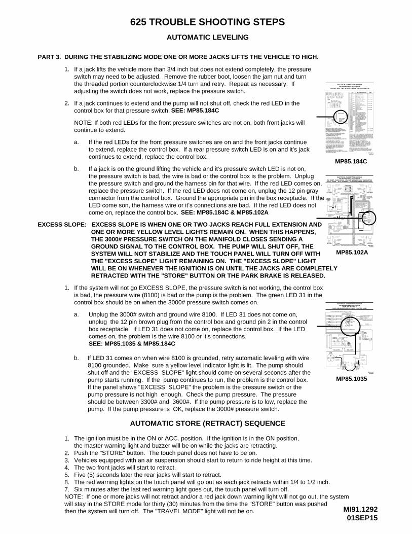
MI91.129201SEP15
625 TROUBLE SHOOTING STEPS
AUTOMATIC LEVELING
PART 3.
1.
a.
DURING THE STABILIZING MODE ONE OR MORE JACKS LIFTS THE VEHICLE TO HIGH.
If a jack lifts the vehicle more than 3/4 inch but does not extend completely, the pressure
If the red LEDs for the front pressure switches are on and the front jacks continue
switch may need to be adjusted. Remove the rubber boot, loosen the jam nut and turnthe threaded portion counterclockwise 1/4 turn and retry. Repeat as necessary. Ifadjusting the switch does not work, replace the pressure switch.
2. If a jack continues to extend and the pump will not shut off, check the red LED in thecontrol box for that pressure switch.
NOTE: If both red LEDs for the front pressure switches are not on, both front jacks will continue to extend.
to extend, replace the control box. If a rear pressure switch LED is on and it’s jack continues to extend, replace the control box.
b. If a jack is on the ground lifting the vehicle and it’s pressure switch LED is not on,the pressure switch is bad, the wire is bad or the control box is the problem. Unplugthe pressure switch and ground the harness pin for that wire. If the red LED comes on,replace the pressure switch. If the red LED does not come on, unplug the 12 pin grayconnector from the control box. Ground the appropriate pin in the box receptacle. If theLED come son, the harness wire or it’s connections are bad. If the red LED does not come on, replace the control box.
EXCESS SLOPE: EXCESS SLOPE IS WHEN ONE OR TWO JACKS REACH FULL EXTENSION AND ONE OR MORE YELLOW LEVEL LIGHTS REMAIN ON. WHEN THIS HAPPENS, THE 3000# PRESSURE SWITCH ON THE MANIFOLD CLOSES SENDING A GROUND SIGNAL TO THE CONTROL BOX. THE PUMP WILL SHUT OFF, THE SYSTEM WILL NOT STABILIZE AND THE TOUCH PANEL WILL TURN OFF WITH THE "EXCESS SLOPE" LIGHT REMAINING ON. THE "EXCESS SLOPE" LIGHT WILL BE ON WHENEVER THE IGNITION IS ON UNTIL THE JACKS ARE COMPLETELYRETRACTED WITH THE "STORE" BUTTON OR THE PARK BRAKE IS RELEASED.
1. If the system will not go EXCESS SLOPE, the pressure switch is not working, the control boxis bad, the pressure wire (8100) is bad or the pump is the problem. The green LED 31 in thecontrol box should be on when the 3000# pressure switch comes on.
a. Unplug the 3000# switch and ground wire 8100. If LED 31 does not come on, unplug the 12 pin brown plug from the control box and ground pin 2 in the control box receptacle. If LED 31 does not come on, replace the control box. If the LED comes on, the problem is the wire 8100 or it’s connections.
b.
AUTOMATIC STORE (RETRACT) SEQUENCE
1. The ignition must be in the ON or ACC. position. If the ignition is in the ON position,the master warning light and buzzer will be on while the jacks are retracting.
2. Push the "STORE" button. The touch panel does not have to be on.
4. The two front jacks will start to retract.5. Five (5) seconds later the rear jacks will start to retract.8. The red warning lights on the touch panel will go out as each jack retracts within 1/4 to 1/2 inch.7. Six minutes after the last red warning light goes out, the touch panel will turn off.NOTE: If one or more jacks will not retract and/or a red jack down warning light will not go out, the systemwill stay in the STORE mode for thirty (30) minutes from the time the "STORE" button was pushedthen the system will turn off. The "TRAVEL MODE" light will not be on.
SWITCHPARK BRAKE
LEFT FRONT
LEFT REAR
TOUCH PANEL - JACK WARNING LIGHTS AND PRESSURE SWITCHESAIR DUMP - PARK BRAKE - MASTER WARNING LIGHT AND BUZZER
LIGHT
MASTERWARNING
F1
LED
FUSE
+12V
PIN 1
RIGHT SIDE
LEFT SIDEFRONT
GROUND
REAR
PROBLEM WITH THE CONTROL BOX, TOUCH PANEL IF A YELLOW LED IS NOT LIT, THERE IS A
NO RED LED IS COMING ON THERE MAY BEPROBLEM WITH INPUT VOLTAGE IN THE
NOTE: A LIT YELLOW LED INDICATES THEREIS A GROUND SIGNAL TO TURN THE
A LIT RED LED INDICATES THERE IS VOLTAGE ON IT’S CORRESPONDING OUTPUT PIN.
CORRESPONDING RED LED IS OFF, EITHERIT’S FUSE IS BLOWN OR THE RELAY IS BAD.
IF THE YELLOW LED’S ARE WORKING BUT
IF A YELLOW LED IS LIT AND THE
BOX CONNECTION INFORMATION.ELECTRICAL CONNECTION DIAGRAM - CONTROLINFORMATION ABOUT PIN CONNECTIONS SEE NOTE: FOR DETAILED INPUT / OUTPUT
OR CONNECTION CABLE
4-PIN CONNECTOR.
CORRESPONDING RELAY ON.
SENSING UNIT
2
1
RE
AR
RIG
HT
ELECTRICAL CONNECTION DIAGRAM
GRAY4 PIN
625 SERIES LEVELING SYSTEM
WARNINGSWITCH
PRESSURE
6230 - 6231
MASTER RELAYS
DIAGRAM - 625 SERIES
MANIFOLD - PUMP AND
SEE ELECTRICAL CONNECTION
LEVELING SYSTEM - LEVELING
SWITCHWARNING
MP85.102A
76999001 - TO
9301
6231
93006230
PARK BRAKE
SWITCH
4000
AB
4200
SWITCHWARNING
6235
CONNECTIONPILOT AIR DUMP
PRESSURE
93019300
62306231
DIODE
BC
TO HWHGROUNDSTUD
LIGHT
A
9000
TO ACCESSORY
TO IGNITION
6111
7699
DIODE
5AMPFUSE
6111
7699
7699
9000
BUZZER
+ _
1000
PRESSURESWITCH
6110
AB
1200
SWITCHWARNING
6235
6120
UNDERSTAND OPERATOR’S MANUAL BEFORE USING. BLOCK FRAME AND TIRES
EXCESS
CAUTION!
SECURELY BEFORE REMOVING TIRES OR CRAWLING UNDER VEHICLE.
OFF
LEVEL
DUMPSTORE
HYD
TRAVELMODE
PARK/BRAKE
SLOPE
NOT IN
HWH COMPUTERIZED LEVELING
TOUCH PANEL
GREEN
SWITCH
62353000
AB
3200
16FEB05
RIGHT REAR
MP85.102A
BLACK
12 PINBLACK
PRESSURE
8 PIN
12 PINGRAY
BY OEMCONNECTION
12 PINBROWN
12 PIN
PILOT DUMP
62352000
93019300
2200
AB
SWITCH
RIGHT FRONT
21-YELLOW LEFT FRONT WARN SW
NOT USEDNOT USED
BOARD ENABLEACCESSORY IN
PARK BRAKE
LINK LIGHT
IT IS ONLY USED WITH PILOT OPERATED AIR DUMPVEHICLES EQUIPPED WITH HWH AIR DUMP SYSTEMS.NOTE: THE TRAVEL RELAY IS NOT USED ON
TRAVEL MODE AND THE IGNITION IS ON.
LATER LED’S 3 AND 19 WILL TURN OFF.IS PUSHED, LED’s 7 AND 20 WILL TURN OFF. 5 SECONDSPUSHED. TWO SECONDS AFTER THE "STORE" BUTTONTOUCH PANEL IS ON UNLESS THE "STORE" BUTTON ISLED’S 19 AND 20 (YELLOW) WILL BE ON WHENEVER THE
WILL BE ON IF THE LEVELING SYSTEM IS IN THE
NOTE: THE TRAVEL RELAY IS WIRED AS A NORMALLY CLOSED RELAY. WHEN THE YELLOWLED (17) IS ON THE RELAY CONTACTS WILL OPEN.THE RED LED (18) WILL NOT BE ON. THE RED LED
MP85.184C
RIGHT FRONT PRESS SW
LEFT REAR PRESS SW
JACK INTERRUPT
RIGHT REAR PRESS SW
50 LB PRESS SW INPUTMASTER WARN CONTROL3000 LB PRESS SW INPUT
MASTER WARNINGACCESSORY OUT FOR
LEFT REAR WARN SWLEFT FRONT PRESS SW
RIGHT REAR WARN SWRIGHT FRONT WARN SW
FUSE 7.5 AMP26
28
27
23
24
25
21
22
39
+12 ACC TOTOUCHPANEL
3129 30 3432 33 35
39-RED
SYSTEMS.
23-YELLOW22-YELLOW
24-YELLOW
30-YELLOW
26-RED
28-RED27-RED
29-RED
25-RED
33-GREEN
31-GREEN
36-RED37-RED38-RED
35-RED34-RED
32-RED3736 38
F11
F12
F10
27APR05MP85.184C
F10 - 10 AMP
F11 - 3 AMP
LEFT REAR COIL
PUMP OUTPUT
DUMP OUTPUT
TRAVEL COIL
PUMP COIL
DUMP COIL
ELECTRICAL CONNECTION DIAGRAM
625 SERIES LEVELING SYSTEM
RIGHT FRONT COIL
LEFT FRONT COIL
MASTER RELAY COIL
LEFT FRONT OUTPUT
TRAVEL OUTPUT
RIGHT FRONT OUTPUT
MASTER RELAY OUTPUT
RELAY DESCRIPTION
RIGHT REAR COIL
LEFT REAR OUTPUT
RIGHT REAR OUTPUT
CONTROL BOX - LED - FUSE LOCATION AND DESCRIPTION
16
15
RIG
HT
RE
LAY
F7
DU
MP
RE
LAY
MA
ST
ER
F6
4
12
11
LEF
TR
EA
R
3
F2 6
5
19
14
13
CR
X2
FR
ON
T
F9
F8
PU
MP
17
TR
AV
EL
FR
ON
TF
3 8
18
7
LEF
TF
4 20
CR
X1
LED
1-YELLOW
5-YELLOW
7-YELLOW
3-YELLOW
6-RED
8-RED
4-RED
2-RED
20-YELLOW19-YELLOW
17-YELLOW
15-YELLOW
13-YELLOW
16-RED
18-RED
12-RED
14-RED
11-YELLOW
CRX 2CRX 1
F8 - 5 AMP
F7 - 5 AMP
F6 - 5 AMP
F9 - 5 AMP
F3 - 15 AMP
F4 - 15 AMP
F2 - 15 AMP
F1 - 15 AMP
FUSE
SEE: MP85.184C
SEE: MP85.184C & MP85.102A
SEE: MP85.1035 & MP85.184CGROUND STUD6230 - TO HWH
LEVELING MANIFOLD
ELECTRICAL CONNECTION DIAGRAM625 SERIES LEVELING SYSTEM
PUMP AND MASTER RELAYS WITH PILOT AIR DUMPLEVELING MANIFOLD
MOTORPUMP
MOTOR
#7
#6
RELAYPUMP
#4
#5
6231 - TO HWH
#9
GROUND STUD
TO PUMP+
8600
HWH GROUND
MANIFOLD
STUD
TO HWH GROUND STUD - 6240TO 3000 LB PRESSURE SWITCH - 8100
TO 50 LB PRESSURE SWITCH - 8101
1400
44006240
6240
AB
AB
24007600
7601
BA
AB
3400
MANIFOLD NOT SHOWNNOTE: ROOM EXTENSION
LEVELING
P.E
.DP
.E.D
P.E
.DP
.E.D
RF
RR
LR
LF
BLACK8 PIN
RELAYMASTER
#1
#3
#8
#2
BATTERY
8500 6800
TO +12V
6100
27APR05MP85.1035
12 PINGRAY
GROUND STUDTO HWH
SYSTEM - AIR DUMP625 SERIES LEVELINGDIAGRAMCONNECTIONSEE ELECTRICAL
12 PINBLACK
BROWN
9300
GRAY4 PIN
12 PIN
6230
9301
MP85.1035
If LED 31 comes on when wire 8100 is grounded, retry automatic leveling with wire 8100 grounded. Make sure a yellow level indicator light is lit. The pump should shut off and the "EXCESS SLOPE" light should come on several seconds after the pump starts running. If the pump continues to run, the problem is the control box.If the panel shows "EXCESS SLOPE" the problem is the pressure switch or the pump pressure is not high enough. Check the pump pressure. The pressure should be between 3300# and 3600#. If the pump pressure is to low, replace the pump. If the pump pressure is OK, replace the 3000# pressure switch.
Vehicles equipped with an air suspension should start to return to ride height at this time.3.
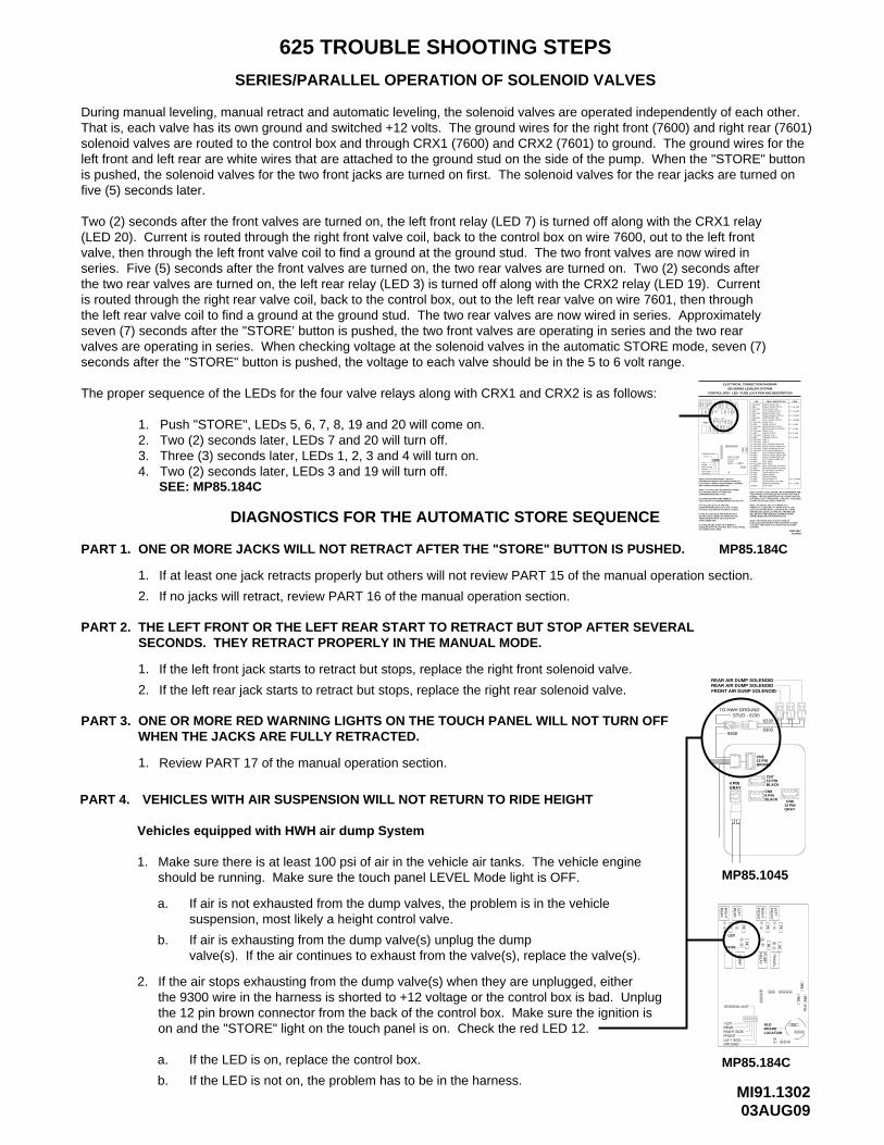
MI91.130203AUG09
625 TROUBLE SHOOTING STEPS
SERIES/PARALLEL OPERATION OF SOLENOID VALVES
DIAGNOSTICS FOR THE AUTOMATIC STORE SEQUENCE
During manual leveling, manual retract and automatic leveling, the solenoid valves are operated independently of each other.That is, each valve has its own ground and switched +12 volts. The ground wires for the right front (7600) and right rear (7601)solenoid valves are routed to the control box and through CRX1 (7600) and CRX2 (7601) to ground. The ground wires for theleft front and left rear are white wires that are attached to the ground stud on the side of the pump. When the "STORE" buttonis pushed, the solenoid valves for the two front jacks are turned on first. The solenoid valves for the rear jacks are turned onfive (5) seconds later.
Two (2) seconds after the front valves are turned on, the left front relay (LED 7) is turned off along with the CRX1 relay(LED 20). Current is routed through the right front valve coil, back to the control box on wire 7600, out to the left frontvalve, then through the left front valve coil to find a ground at the ground stud. The two front valves are now wired inseries. Five (5) seconds after the front valves are turned on, the two rear valves are turned on. Two (2) seconds afterthe two rear valves are turned on, the left rear relay (LED 3) is turned off along with the CRX2 relay (LED 19). Currentis routed through the right rear valve coil, back to the control box, out to the left rear valve on wire 7601, then throughthe left rear valve coil to find a ground at the ground stud. The two rear valves are now wired in series. Approximatelyseven (7) seconds after the "STORE’ button is pushed, the two front valves are operating in series and the two rearvalves are operating in series. When checking voltage at the solenoid valves in the automatic STORE mode, seven (7)seconds after the "STORE" button is pushed, the voltage to each valve should be in the 5 to 6 volt range.
The proper sequence of the LEDs for the four valve relays along with CRX1 and CRX2 is as follows:
1. Push "STORE", LEDs 5, 6, 7, 8, 19 and 20 will come on.2. Two (2) seconds later, LEDs 7 and 20 will turn off.3. Three (3) seconds later, LEDs 1, 2, 3 and 4 will turn on.4. Two (2) seconds later, LEDs 3 and 19 will turn off.
ONE OR MORE JACKS WILL NOT RETRACT AFTER THE "STORE" BUTTON IS PUSHED.PART 1.
If at least one jack retracts properly but others will not review PART 15 of the manual operation section.1.
If no jacks will retract, review PART 16 of the manual operation section.2.
THE LEFT FRONT OR THE LEFT REAR START TO RETRACT BUT STOP AFTER SEVERALPART 2. SECONDS. THEY RETRACT PROPERLY IN THE MANUAL MODE.
2.
1. If the left front jack starts to retract but stops, replace the right front solenoid valve.
If the left rear jack starts to retract but stops, replace the right rear solenoid valve.
WHEN THE JACKS ARE FULLY RETRACTED.ONE OR MORE RED WARNING LIGHTS ON THE TOUCH PANEL WILL NOT TURN OFFPART 3.
1. Review PART 17 of the manual operation section.
F1
LED
FUSE
+12V
PIN 1
RIGHT SIDE
LEFT SIDEFRONT
GROUND
REAR
PROBLEM WITH THE CONTROL BOX, TOUCH PANEL IF A YELLOW LED IS NOT LIT, THERE IS A
NO RED LED IS COMING ON THERE MAY BEPROBLEM WITH INPUT VOLTAGE IN THE
NOTE: A LIT YELLOW LED INDICATES THEREIS A GROUND SIGNAL TO TURN THE
A LIT RED LED INDICATES THERE IS VOLTAGE ON IT’S CORRESPONDING OUTPUT PIN.
CORRESPONDING RED LED IS OFF, EITHERIT’S FUSE IS BLOWN OR THE RELAY IS BAD.
IF THE YELLOW LED’S ARE WORKING BUT
IF A YELLOW LED IS LIT AND THE
BOX CONNECTION INFORMATION.ELECTRICAL CONNECTION DIAGRAM - CONTROLINFORMATION ABOUT PIN CONNECTIONS SEE NOTE: FOR DETAILED INPUT / OUTPUT
OR CONNECTION CABLE
4-PIN CONNECTOR.
CORRESPONDING RELAY ON.
SENSING UNIT
RE
AR
RIG
HT
2
1
ELECTRICAL CONNECTION DIAGRAM
LEFT REAR COIL
PUMP OUTPUT
DUMP OUTPUT
TRAVEL COIL
PUMP COIL
DUMP COIL
625 SERIES LEVELING SYSTEM
RIGHT FRONT COIL
LEFT FRONT COIL
MASTER RELAY COIL
LEFT FRONT OUTPUT
TRAVEL OUTPUT
RIGHT FRONT OUTPUT
MASTER RELAY OUTPUT
RELAY DESCRIPTION
RIGHT REAR COIL
LEFT REAR OUTPUT
RIGHT REAR OUTPUT
CONTROL BOX - LED - FUSE LOCATION AND DESCRIPTION
NOT USEDNOT USED
BOARD ENABLEACCESSORY IN
PARK BRAKE
LINK LIGHT
IT IS ONLY USED WITH PILOT OPERATED AIR DUMPVEHICLES EQUIPPED WITH HWH AIR DUMP SYSTEMS.NOTE: THE TRAVEL RELAY IS NOT USED ON
TRAVEL MODE AND THE IGNITION IS ON.
LATER LED’S 3 AND 19 WILL TURN OFF.IS PUSHED, LED’s 7 AND 20 WILL TURN OFF. 5 SECONDSPUSHED. TWO SECONDS AFTER THE "STORE" BUTTONTOUCH PANEL IS ON UNLESS THE "STORE" BUTTON ISLED’S 19 AND 20 (YELLOW) WILL BE ON WHENEVER THE
WILL BE ON IF THE LEVELING SYSTEM IS IN THE
NOTE: THE TRAVEL RELAY IS WIRED AS A NORMALLY CLOSED RELAY. WHEN THE YELLOWLED (17) IS ON THE RELAY CONTACTS WILL OPEN.THE RED LED (18) WILL NOT BE ON. THE RED LED
MP85.184C
RIGHT FRONT PRESS SW
LEFT REAR PRESS SW
JACK INTERRUPT
RIGHT REAR PRESS SW
50 LB PRESS SW INPUTMASTER WARN CONTROL3000 LB PRESS SW INPUT
MASTER WARNINGACCESSORY OUT FOR
LEFT REAR WARN SWLEFT FRONT PRESS SW
RIGHT REAR WARN SWRIGHT FRONT WARN SWLEFT FRONT WARN SW
39
SYSTEMS.
33-GREEN
36-RED37-RED38-RED
35-RED34-RED
39-RED
FUSE 7.5 AMP
PU
MP
TR
AV
EL
RE
LAY
MA
ST
ER
RE
LAY
26
28
27
23
24
25
21
22
DU
MP
+12 ACC TOTOUCHPANEL
3129 30 3432 33 35
16
15
RIG
HT
CR
X2
FR
ON
T
LEF
TR
EA
R
F6
4
12
11
3
F2 6
5
19
14
13
F7
CR
X1
FR
ON
TLE
FT
F3 8
18
7
17
F8
F4 20
F9
13-YELLOW
20-YELLOW19-YELLOW
17-YELLOW
15-YELLOW16-RED
18-RED
14-RED
23-YELLOW22-YELLOW
24-YELLOW
30-YELLOW
26-RED
28-RED27-RED
29-RED
25-RED
31-GREEN32-RED
21-YELLOW
F11
F12
F10
3736 38
CRX 2CRX 1
LED
1-YELLOW
5-YELLOW
7-YELLOW
3-YELLOW
6-RED
8-RED
4-RED
2-RED
12-RED11-YELLOW
27APR05MP85.184C
F10 - 10 AMP
F11 - 3 AMP
F8 - 5 AMP
F7 - 5 AMP
F9 - 5 AMP
F3 - 15 AMP
F4 - 15 AMP
F2 - 15 AMP
F1 - 15 AMP
F6 - 5 AMP
FUSE
SEE: MP85.184C
suspension, most likely a height control valve.If air is not exhausted from the dump valves, the problem is in the vehicle
If the LED is not on, the problem has to be in the harness.
on and the "STORE" light on the touch panel is on. Check the red LED 12. the 12 pin brown connector from the back of the control box. Make sure the ignition isthe 9300 wire in the harness is shorted to +12 voltage or the control box is bad. UnplugIf the air stops exhausting from the dump valve(s) when they are unplugged, either
valve(s). If the air continues to exhaust from the valve(s), replace the valve(s).If air is exhausting from the dump valve(s) unplug the dump
should be running. Make sure the touch panel LEVEL Mode light is OFF.Make sure there is at least 100 psi of air in the vehicle air tanks. The vehicle engine
VEHICLES WITH AIR SUSPENSION WILL NOT RETURN TO RIDE HEIGHT
Vehicles equipped with HWH air dump System
a.
b.
1.
b.
2.
a.
PART 4.
If the LED is on, replace the control box.
F3
F4
F2F1
MP85.184C
29
OLDBOARDLOCATION
LEFT SIDE
RIGHT SIDE
GROUND
FRONT
REAR+12V
4
SENSING UNIT
FUSE
LED
2
21
22
24
23
DU
MP
12
11
F6
RE
LAY
PU
MP
6
F8
16
15
38
379
(39)
36 38
F12
3736
PF
3
3430 3332 35
F10
17
F9
TR
AV
EL
8
18
PF
4(F
11)
CN3
BROWN
12 PINBLACK
CN7
CN8
BLACK8 PIN
MP85.1045
3
RE
AR
RIG
HT
1
RE
AR
LEF
T
RIG
HT
5
FR
ON
T
4 PINGRAY
12 PIN
LEF
TF
RO
NT
7
GRAY12 PINCN6
6230
9300
REAR AIR DUMP SOLENOIDREAR AIR DUMP SOLENOIDFRONT AIR DUMP SOLENOID
STUD - 6230TO HWH GROUND
9300
AB
P.E
.D
B A AB B A
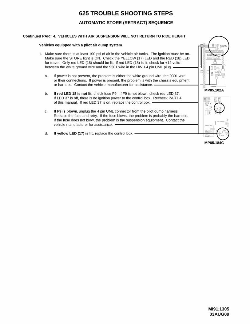
MI91.130503AUG09
625 TROUBLE SHOOTING STEPS
AUTOMATIC STORE (RETRACT) SEQUENCE
VEHICLES WITH AIR SUSPENSION WILL NOT RETURN TO RIDE HEIGHTContinued PART 4.
Vehicles equipped with a pilot air dump system
Make sure there is at least 100 psi of air in the vehicle air tanks. The ignition must be on.1.Make sure the STORE light is ON. Check the YELLOW (17) LED and the RED (18) LED
or harness. Contact the vehicle manufacturer for assistance.
+12VREAR
FRONT
GROUND
RIGHT SIDE
LEFT SIDE
LOCATION
(39)
9
BOARDOLD
383736
F12
36 3837
SENSING UNIT
31
FUSE
LED
2
DU
MP
4
F1
11
12
F2
RE
AR
RIG
HT
RE
AR
LEF
T
75
32
F9
F4
21
23
24
223029
15
16
RE
LAY
F6
6
F8
PU
MP
TR
AV
EL
17
F3
18
8
F10
353433
(F11)
PF
4P
F3
RIG
HT
FR
ON
T
FR
ON
TLE
FT
MP85.184C
a.
b.
for travel. Only red LED (18) should be lit. If red LED (18) is lit, check for +12 volts between the white ground wire and the 9301 wire in the HWH 4 pin UML plug.
If power is not present, the problem is either the white ground wire, the 9301 wireor their connections. If power is present, the problem is with the chassis equipment
c.
If red LED 18 is not lit,If LED 37 is off, there is no ignition power to the control box. Recheck PART 4of this manual. If red LED 37 is on, replace the control box.
If F9 is blown, Replace the fuse and retry. If the fuse blows, the problem is probably the harness.If the fuse does not blow, the problem is the suspension equipment. Contact thevehicle manufacturer for assistance.
d.
check fuse F9. If F9 is not blown, check red LED 37.
unplug the 4 pin UML connector from the pilot dump harness.
If yellow LED (17) is lit, replace the control box.
CN7
8 PIN
BLACK12 PIN
BLACK
76999000 4 PIN
GRAYCN8
CN312 PINBROWN
12 PINGRAY
CN6
LEVELING SYSTEM - LEVELING
SEE ELECTRICAL CONNECTION
MANIFOLD - PUMP RELAY
DIAGRAM - 325 SERIES
623093019300
CONNECTIONPILOT DUMP
BY OEM
MP85.102A
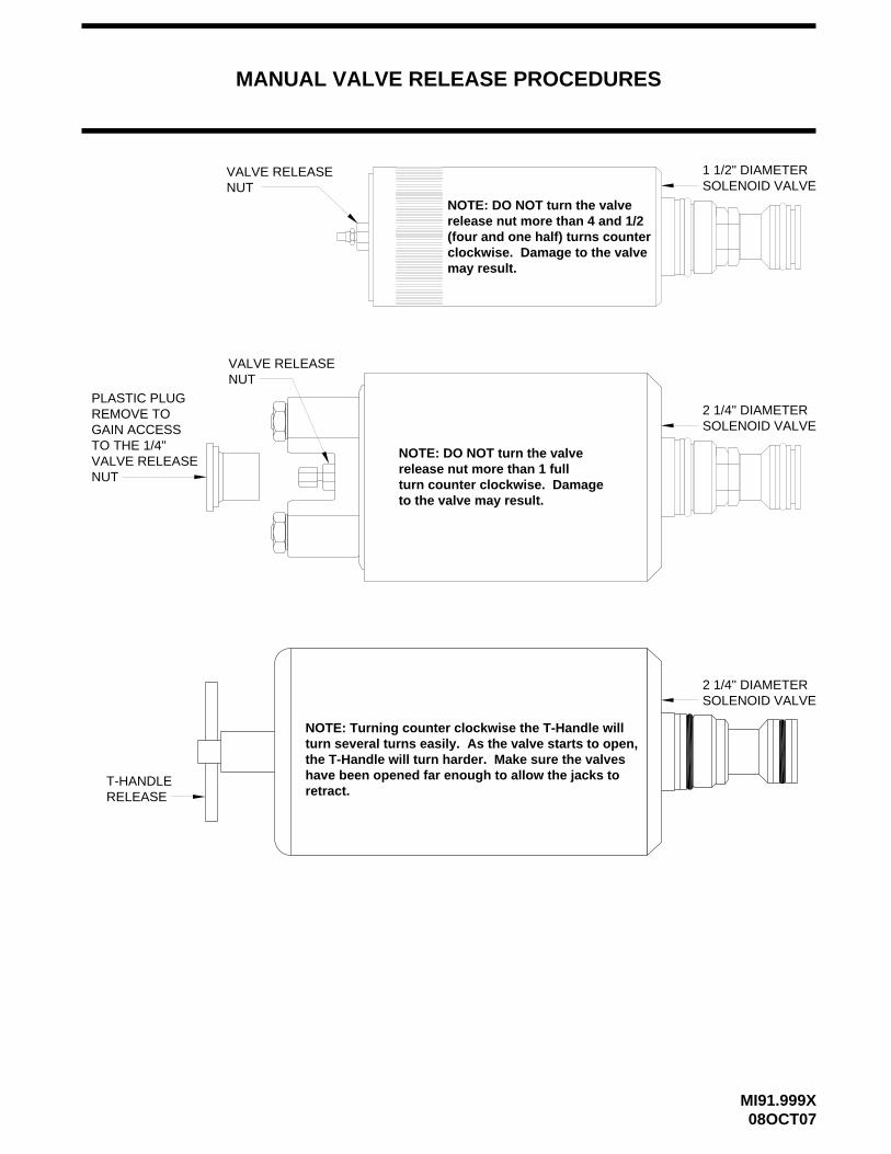
MANUAL VALVE RELEASE PROCEDURES
MI91.999X08OCT07
VALVE RELEASE NUT
1 1/2" DIAMETERSOLENOID VALVE
NOTE: DO NOT turn the valverelease nut more than 4 and 1/2 (four and one half) turns counter clockwise. Damage to the valvemay result.
VALVE RELEASE NUT
to the valve may result.turn counter clockwise. Damage
NOTE: DO NOT turn the valverelease nut more than 1 full
PLASTIC PLUGREMOVE TOGAIN ACCESSTO THE 1/4"VALVE RELEASENUT
SOLENOID VALVE2 1/4" DIAMETER
2 1/4" DIAMETERSOLENOID VALVE
T-HANDLERELEASE
turn several turns easily. As the valve starts to open, NOTE: Turning counter clockwise the T-Handle will
the T-Handle will turn harder. Make sure the valves have been opened far enough to allow the jacks toretract.

01JUN10MP45.271M
MP85.6148
SENSING UNIT MAINTENANCE/SERVICE
± 1 inch side to side on a 36 foot vehicle. Typical leveling results will be better.The sensing unit has an accuracy tolerance of ± 5.4 inches front to rear and
SENSING UNIT ACCURACY TOLERANCE
SENSING UNIT ADJUSTMENT
There are four LED’s on the Sensing Unit, A,B,C and D. Refer
while making the A-C adjustment.adjustments first, then hold the adjustment nut from movingControl Box. If two LED’s are on, it is best to make the B-D be a problem with the Sensing Unit or the mounting of the be turned more than 3/4 turn to turn the LED out, there may to be turned more than 1/2 flat or the adjustment screw has to screw will turn out LED’s A and C. If the adjustment nut has the adjustment nut to turn out LED’s B and D. The adjustment to the drawing below. The Sensing Unit is adjusted by turning
MAY BE DIFFERENTLED’S - LOCATION
A
C
TOP VIEW - SENSING UNIT
D B
7/8, 3/4, 1/2, 5/16 or 1/4 sizes will be needed.screw driver or sockets w/driver or box end wrenches ofadjustments to the Sensing Unit are needed. A Phillipsare yellow LEVEL lights lit on the Touch Panel, manualTouch Panel, the sensing unit is properly adjusted. If thereWith the vehicle level , if there are no yellow light lit on the
Control Box is mounted to the power unit/valve assembly.The Sensing Unit is mounted inside the Control Box. The
LEVEL lights. Recheck the level. If more adjustment is
"tweaking" process until the system levels the vehicle touch panel. Recheck with a level. Repeat the relevel the vehicle using the yellow level lights on the the front up more. Again, unlevel the vehicle then the front yellow light to stay on slightly longer to bring instructions for LED’s A, B, C, and D. This will allow the OPPOSITE direction that is given in the above Move the adjustment for that light very, very, slightly in which sensing unit light is the front light, A-B-C or D. yellow level light is turning off too soon. Determine the vehicle, the front is still low. This means the front Example: After the initial adjustment and releveling
sensing unit, ignoring the LED’s on the sensing unit. yellow level lights go out, instead just "tweak" the needed, DO NOT try to adjust the sensing unit until the
SIDE VIEW - CONTROL BOX
NUT (5/16" OLD) - (1/2" NEW)ADJUSTMENT
properly.
lights are on. Level the vehicle according to the yellow vehicle to an unlevel position so one or two yellow IMPORTANT: When all 4 LED’s are off, move the
If LED (D) is lit: Turn the adjustment nut CLOCKWISE
If LED (B) is lit: Turn the adjustment nut COUNTER
If LED (C) is lit: Turn the adjustment screw CLOCKWISE
If LED (A) is lit: Turn the adjustment screw COUNTER
NOTE: If opposing LED’s are lit, there is a problem with
until the LED is off.
CLOCKWISE until the LED is off.
until the LED is off.
CLOCKWISE until the LED is off.
the Sensing Unit.
ADJUSTMENT SCREWSCREW (Phillips or 1/4")
ADJUSTMENT
NUT (7/8" or 3/4")
(OLD STYLE)ADJUSTMENT
ADJUSTMENT NUT (5/16" OLD) - (1/2" NEW)
ADJUSTMENTNUT (7/8" or 3/4")
BOX WALLCONTROL
(OLD STYLE)
the control box/sensing unit.be placed on a flat surface close to the mounting location ofuse a small bubble level. If using a bubble level, the level shouldvehicle trim line to determine level. An alternative would be toto manually level the vehicle. It is recommended to use theposition the vehicle on a level surface or use the leveling systemTo adjust the sensing unit, first the vehicle must be level. Either

MP45.272M17SEP07
JP1 AND JP2 - CONTROL BOX ORIENTATION (Page 1 of 2)
JP3JP2
JP4
JP1 SHIPPEDPOSITION POSITION
MOVED
FOR SHIPPING PURPOSES THE (4) JUMPERS ARE SLID ONTO ONE SIDE OF JP1 THROUGH JP4. MOVE ONLY THE JUMPERS NEEDED TO DETERMINE ORIENTATION AND SUSPENSION. LEAVING THE REMAINING JUMPERS AS THEY ARE SHIPPED WILL NOT CAUSE PROBLEMS.
MOVE JUMPERS JP1 AND JP2 ACCORDING TO THE ORIENTATION OF THE CONTROL BOX. USE THE DRAWINGSPROVIDED TO DETERMINE WHICH APPLICATION IS FOR THE ORIENTATION OF YOUR CONTROL BOX.
ELECTRONIC SENSING UNIT REPLACEMENT
325 AND 625 AFTER MARKET INSTALLATIONS OR
INSTRUCTION SHEET - JUMPER PLACEMENT FORTHOROUGHLYBEFOREPROCEEDING
INSTRUCTIONSREAD
STOP
THE FOLLOWING DRAWINGS SHOW THE SENSING UNIT, INSIDE THE CONTROL BOX, AS VIEWED WHEN LOOKING DOWN FROM THE TOP OF THE CONTROL BOX. REMOVE THE RUBBER RING AND PLASTIC COVER ONLY IF NEEDED. THE RING AND COVER MUST BE REINSTALLED.
FRONT OF VEHICLE FRONT OF VEHICLE
FRONT OF VEHICLEFRONT OF VEHICLE
PLEXIGLASS PLEXIGLASS
JUMPERS
JUMPERS
PLEXIGLASS
PLEXIGLASS
JUMPERS MOVE - JP2 ONLYJUMPERS
IN ORDER TO SET THE JUMPERS AS NEEDED TO PROGRAM THE SENSING UNIT TO THE COACH.MOUNTED ORIENTATION OF THE CONTROL BOX ASSEMBLY AND THE SUSPENSION TYPE MUST BE ESTABLISHED OF AN ELECTRONIC SENSING UNIT DO NOT ASSUME THAT THE SENSING UNIT JUMPERS ARE PRE-SET. THEREPLACEMENT SITUATIONS ARE PROGRAMMABLE. DURING INSTALLATION OF A SYSTEM OR REPLACEMENTIMPORTANT: 325 AND 625 ELECTRONIC SENSING UNITS USED IN AFTER MARKET INSTALLATIONS OR
1 2 3 4
4 3 2 1
1234 1
32
4
LEAVE JP1AND JP2 AS
MOVE - JP1 ONLY
SHIPPED
MOVE - JP1 AND JP2
MI15.100A
NOTE: AFTER MOVING THE JUMPERS, REMOVE AND REAPPLY +12 POWERFOR THE CONTROL BOX. THIS WILL "RE-BOOT" THE SENSING UNIT.

MP45.273M17SEP07
JP3 AND JP4 - CONTROL SUSPENSION TYPE (Page 2 of 2)
MOVE JUMPERS JP3 AND JP4 ACCORDING TO THE TYPE OF SUSPENSION ON THE VEHICLE.
LEAVE JUMPER JP4 AS SHIPPED, MOVE JP3 ONLY.
LEAVE JUMPERS JP3 AND JP4 AS SHIPPED.
JUMPERS JP3 AND JP4 DETERMINE SUSPENSION TYPE.
NEITHER JUMPER NEEDS TO BE MOVED.
AIR -
SPRING -
JP3JP4
DIAGRAM BELOW SHOWS AIR SUSPENSION SETUP.
ELECTRONIC SENSING UNIT REPLACEMENT
325 AND 625 AFTER MARKET INSTALLATIONS OR
INSTRUCTION SHEET - JUMPER PLACEMENT FORTHOROUGHLYBEFOREPROCEEDING
INSTRUCTIONSREAD
STOP
IMPORTANT: 325 AND 625 ELECTRONIC SENSING UNITS USED IN AFTER MARKET INSTALLATIONS ORREPLACEMENT SITUATIONS ARE PROGRAMMABLE. DURING INSTALLATION OF A SYSTEM OR REPLACEMENTOF AN ELECTRONIC SENSING UNIT DO NOT ASSUME THAT THE SENSING UNIT JUMPERS ARE PRE-SET. THEMOUNTED ORIENTATION OF THE CONTROL BOX ASSEMBLY AND THE SUSPENSION TYPE MUST BE ESTABLISHED IN ORDER TO SET THE JUMPERS AS NEEDED TO PROGRAM THE SENSING UNIT TO THE COACH.
MI15.100B
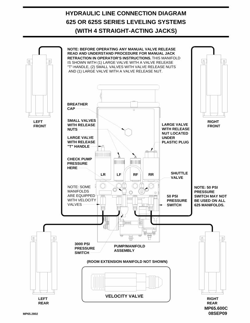
NOTE: BEFORE OPERATING ANY MANUAL VALVE RELEASEREAD AND UNDERSTAND PROCEDURE FOR MANUAL JACK RETRACTION IN OPERATOR’S INSTRUCTIONS.
HYDRAULIC LINE CONNECTION DIAGRAM
MP65.600C08SEP09
(WITH 4 STRAIGHT-ACTING JACKS)
PUMP/MANIFOLDASSEMBLY
SHUTTLEVALVE
LEFTFRONT
RIGHTFRONT
RIGHTREAR
LEFTREAR
625 OR 625S SERIES LEVELING SYSTEMS
BREATHERCAP
VELOCITY VALVE
NOTE: SOMEMANIFOLDSARE EQUIPPEDWITH VELOCITYVALVES
PRESSURE50 PSI
SWITCH
PRESSURE3000 PSI
SWITCH
(ROOM EXTENSION MANIFOLD NOT SHOWN)
THIS MANIFOLD
"T"-HANDLE, (2) SMALL VALVES WITH VALVE RELEASE NUTS AND (1) LARGE VALVE WITH A VALVE RELEASE NUT.
IS SHOWN WITH (1) LARGE VALVE WITH A VALVE RELEASE
LF RFLR RR
NUTS
SMALL VALVESWITH RELEASE
CHECK PUMPPRESSUREHERE
MP65.2802
625 MANIFOLDS.BE USED ON ALLSWITCH MAY NOTPRESSURENOTE: 50 PSI
LARGE VALVEWITH RELEASE"T" HANDLE
NUT LOCATEDWITH RELEASELARGE VALVE
UNDERPLASTIC PLUG
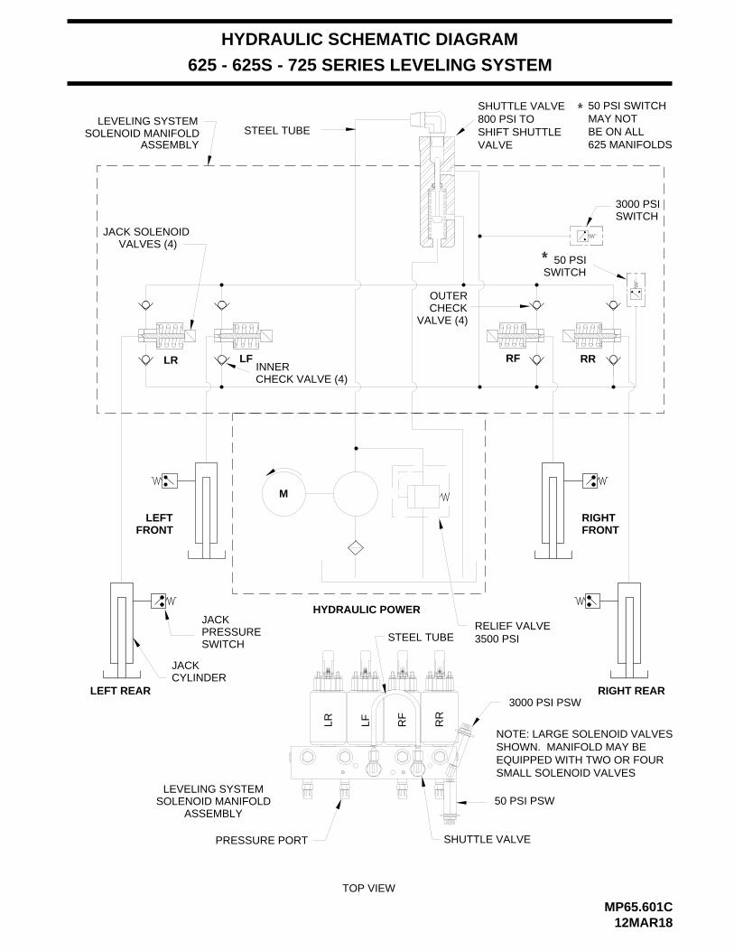
3500 PSI
RR
LR RFLF
50 PSI SWITCH
50 PSISWITCH
JACKPRESSURESWITCH
JACKCYLINDER
LEFT REAR RIGHT REAR
RIGHTFRONT
LEFTFRONT
MP65.601C12MAR18
3000 PSISWITCH
RELIEF VALVE
RR
625 - 625S - 725 SERIES LEVELING SYSTEM
HYDRAULIC SCHEMATIC DIAGRAM
STEEL TUBE
VALVES (4)JACK SOLENOID
M
HYDRAULIC POWER
TOP VIEW
STEEL TUBE
RF
CHECK VALVE (4)INNER
LEVELING SYSTEMSOLENOID MANIFOLD
ASSEMBLY50 PSI PSW
SHUTTLE VALVEPRESSURE PORT
OUTERCHECK
VALVE (4)
LEVELING SYSTEMSOLENOID MANIFOLD
ASSEMBLY
3000 PSI PSW
800 PSI TOSHIFT SHUTTLEVALVE
SHUTTLE VALVEMAY NOTBE ON ALL625 MANIFOLDS
LFLR
NOTE: LARGE SOLENOID VALVESSHOWN. MANIFOLD MAY BEEQUIPPED WITH TWO OR FOURSMALL SOLENOID VALVES

ELECTRICAL CONNECTION DIAGRAM625 SERIES LEVELING SYSTEM
MP85.056C29OCT07
+ _
MASTERWARNING
LIGHT BUZZER
CONNECT TO12V IGNITION
5AMPFUSE
DIODE
76997699
6111 6111
7699
PARK BRAKESWITCH
DIODE 9001 - TOPARK BRAKELIGHT
TOUCH PANEL
GRAY4 PIN
TOUCH PANEL - JACK WARNING LIGHTS AND PRESSURE SWITCHESPARK BRAKE - MASTER WARNING LIGHT AND BUZZER
LF RF
LR RR
AB B A
B A B A
62354000
4200 32006235
3000
62351000
1200 22006235
2000
WARNINGSWITCH
SWITCHPRESSURE PRESSURE
SWITCHWARNING
SWITCH
SWITCHWARNING
SWITCHPRESSURE
SWITCHWARNING
PRESSURESWITCH
SEE 625 SERIES LEVELINGSYSTEM - LEVELINGMANIFOLD - PUMPAND MASTER RELAYS
6121
76999000
9000
6120 - TOACCESSORY
6230 - TO HWHGROUNDSTUD
6800
6120
TOUCHPANELHARNESS
SEE 625 SERIES LEVELING
AND MASTER RELAYSMANIFOLD - PUMPSYSTEM - LEVELING
CAUTION!
SECURELY BEFORE REMOVING TIRES OR CRAWLING UNDER VEHICLE.UNDERSTAND OPERATOR’S MANUAL BEFORE USING. BLOCK FRAME AND TIRES
HWH COMPUTERIZED LEVELINGR
ON
OFF
AUTO
STORE
MODETRAVEL
PARK/BRAKE
NOT IN
SLOPEEXCESS
12 PINGRAY
CN6
CN7
8 PIN
BLACK12 PIN
BLACK
CN8
CN312 PINBROWN
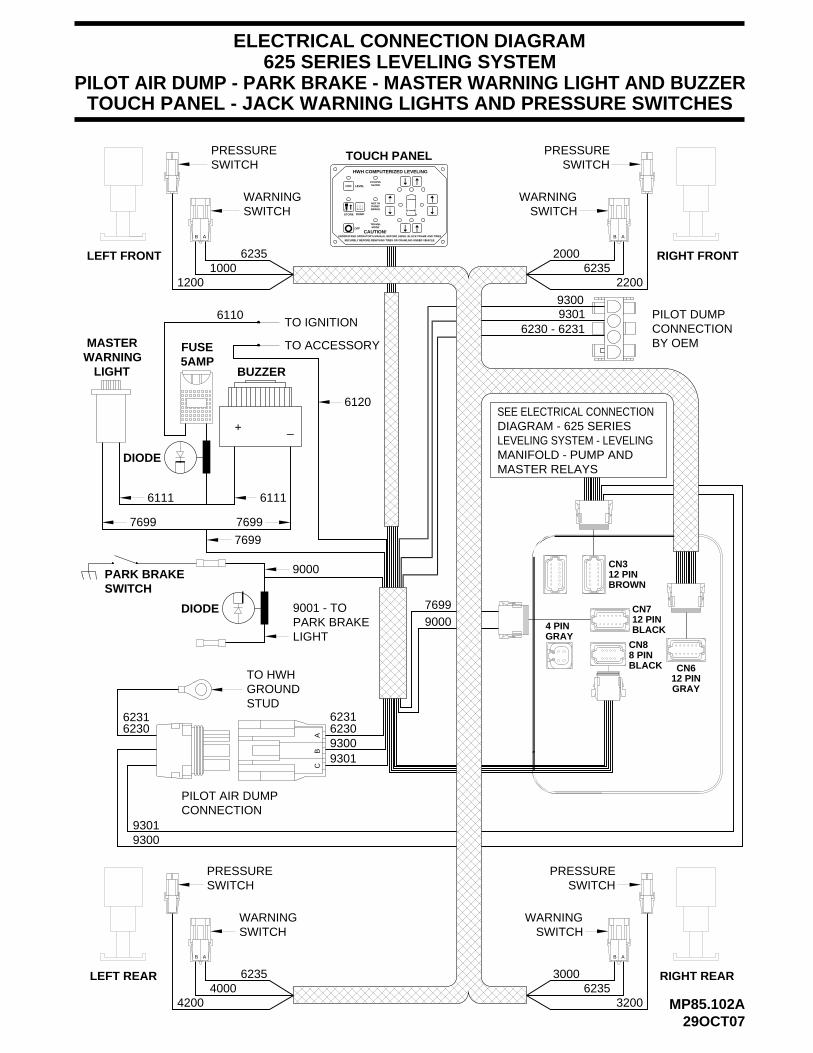
ELECTRICAL CONNECTION DIAGRAM625 SERIES LEVELING SYSTEM
SECURELY BEFORE REMOVING TIRES OR CRAWLING UNDER VEHICLE.
UNDERSTAND OPERATOR’S MANUAL BEFORE USING. BLOCK FRAME AND TIRES
HWH COMPUTERIZED LEVELING
LEVEL
STORE
OFF MODETRAVEL
CAUTION!
SLOPEEXCESS
BRAKEPARK/NOT IN
+ _
MASTERWARNING
LIGHT BUZZER5AMPFUSE
DIODE
76997699
6111 6111
7699
PARK BRAKESWITCH
DIODE 9001 - TOPARK BRAKELIGHT
TOUCH PANEL
GRAY4 PIN
TOUCH PANEL - JACK WARNING LIGHTS AND PRESSURE SWITCHESPILOT AIR DUMP - PARK BRAKE - MASTER WARNING LIGHT AND BUZZER
AB B A
B A B A
62354000
4200 32006235
3000
62351000
1200 22006235
2000
WARNINGSWITCH
SWITCHPRESSURE PRESSURE
SWITCHWARNING
SWITCH
SWITCHWARNING
SWITCHPRESSURE
SWITCHWARNING
PRESSURESWITCH
SEE ELECTRICAL CONNECTION DIAGRAM - 625 SERIES LEVELING SYSTEM - LEVELING MANIFOLD - PUMP AND
HYD
76999000
9000
LEFT REAR
LEFT FRONT
RIGHT REAR
RIGHT FRONT
MP85.102A29OCT07
DUMP
TO IGNITION
TO ACCESSORY
6120
MASTER RELAYS
CB
A
PILOT AIR DUMPCONNECTION
93009301
6230
93009301
TO HWHGROUNDSTUD
6230
6110
6231 6231
6230 - 623193019300
PILOT DUMPCONNECTIONBY OEM
BROWN12 PINCN3
BLACK
12 PINBLACK
CN88 PIN
CN7
12 PINGRAY
CN6

MP85.102K29OCT07
LEVELING MANIFOLDPUMP AND MASTER RELAYS
625 SERIES LEVELING SYSTEMELECTRICAL CONNECTION DIAGRAM
4 PINGRAY
TO 50 LB PRESSURE SWITCH - 8101
LEVELING MANIFOLD
TO 3000 LB PRESSURE SWITCH - 8100
TO HWH GROUND STUD - 6240
BA
AB
BA
BA
62401400
44006240
76013400
76002400
P.E
.DP
.E.D
P.E
.DP
.E.D
LF
LR
RR
RF
8600
6800
LEVELINGMANIFOLD
HWH GROUNDSTUD
TOUCH PANELHARNESS
8500
MOTORPUMP
MOTOR
#9
TO PUMP+
#7
#6
RELAYPUMP
#4
#5
RELAYMASTER
#1
#3
#8
#2
BATTERYTO HOUSE
GROUND STUD6230 - TO HWH6231 - TO HWH
GROUND STUD
8 PINBLACK
CN8
CN7
BLACK12 PIN
CN312 PINBROWN
12 PINGRAY
CN6

PUMP MASTER
LEVELING MANIFOLDPUMP AND MASTER RELAYS WITH PILOT AIR DUMP
625 SERIES LEVELING SYSTEMELECTRICAL CONNECTION DIAGRAM
4 PINGRAY
TO 50 LB PRESSURE SWITCH - 8101
LEVELING MANIFOLD
TO 3000 LB PRESSURE SWITCH - 8100TO HWH GROUND STUD - 6240
BA
AB
BA
BA
62401400
44006240
76013400
76002400
P.E
.DP
.E.D
P.E
.DP
.E.D
LF
LR
RR
RF
RELAY RELAY
TO +12VBATTERYMOTOR
TO PUMP
GROUND STUD6231 - TO HWH
8600
6800
6100
LEVELINGMANIFOLD
HWH GROUNDSTUD
MP85.103529OCT07
6230 - TO HWHGROUND STUD
8500
NOTE: ROOM EXTENSIONMANIFOLD NOT SHOWN
SEE ELECTRICALCONNECTIONDIAGRAM625 SERIES LEVELINGSYSTEM - AIR DUMP
9301
9300
6230
TO HWHGROUND STUD
+
PUMPMOTOR
#2
#8
#3
#1
#4
#5
#6
#7
#9
BROWN12 PINCN3
12 PINBLACK
CN7
CN8
BLACK8 PIN
GRAY12 PINCN6

LEVELING MANIFOLD - AIR DUMPPUMP AND MASTER RELAYS
625 SERIES LEVELING SYSTEMELECTRICAL CONNECTION DIAGRAM
4 PINGRAY
TO 50 LB PRESSURE SWITCH - 8101
FRONT AIR DUMP SOLENOIDREAR AIR DUMP SOLENOIDREAR AIR DUMP SOLENOID
9300
6230B A B A B A
TO HWH GROUNDSTUD - 6230
P.E
.D
9300
BA
LEVELING MANIFOLD
TO 3000 LB PRESSURE SWITCH - 8100TO HWH GROUND STUD - 6240
BA
AB
BA
BA
62401400
44006240
76013400
76002400
P.E
.DP
.E.D
P.E
.DP
.E.D
LF
LR
RR
RF
8600
6800
LEVELINGMANIFOLD
HWH GROUNDSTUD
TOUCH PANELHARNESS
MP85.104529OCT07
PUMPMOTOR
#9
+
MOTORTO PUMP
#7
#6
PUMPRELAY
#4
#5
MASTERRELAY
#3
#1#2
#8
BATTERYTO HOUSE
6230 - TO HWHGROUND STUD
6231 - TO HWHGROUND STUD
12 PINBROWN
CN3
CN7
BLACK12 PIN
8 PINBLACK
CN8
12 PINGRAY
CN6

ELECTRICAL CONNECTION DIAGRAM
625 OR 625S SERIES LEVELING SYSTEMS
CONTROL BOX - LED - FUSE LOCATION AND DESCRIPTION
RELAY DESCRIPTIONLED FUSE
1-YELLOW2-RED3-YELLOW4-RED5-YELLOW6-RED7-YELLOW8-RED11-YELLOW
RIGHT REAR COIL
12-RED
F1 - 15 AMP
F2 - 15 AMP
F3 - 15 AMP
F4 - 15 AMP
F6 - 5 AMP
NOTE: FOR DETAILED INPUT / OUTPUT INFORMATION ABOUTPIN CONNECTIONS SEE ELECTRICAL CONNECTIONDIAGRAM - CONTROL BOX CONNECTION INFORMATION.
IF A YELLOW LED IS LIT AND THE
IF A YELLOW LED IS NOT LIT, THERE IS A PROBLEM WITH
VOLTAGE IN THE 4-PIN CONNECTOR.IS COMING ON THERE MAY BE PROBLEM WITH INPUT IF THE YELLOW LED’S ARE WORKING BUT NO RED LED
IT’S FUSE IS BLOWN OR THE RELAY IS BAD.CORRESPONDING RED LED IS OFF, EITHER
VOLTAGE ON IT’S CORRESPONDING OUTPUT PIN.A LIT RED LED INDICATES THERE IS
SIGNAL TO TURN THE CORRESPONDING RELAY ON.NOTE: A LIT YELLOW LED INDICATES THERE IS A GROUND
13-YELLOW14-RED F7 - 5 AMP
THE CONTROL BOX, TOUCH PANEL OR CONNECTION CABLE.
15-YELLOW16-RED17-YELLOW18-RED19-YELLOW20-YELLOW21-YELLOW22-YELLOW23-YELLOW24-YELLOW25-RED26-RED27-RED28-RED29-RED30-YELLOW31-GREEN32-RED33-GREEN34-RED35-RED36-RED37-RED38-RED
(39) 9-RED
RIGHT REAR OUTPUTLEFT REAR COILLEFT REAR OUTPUTRIGHT FRONT COILRIGHT FRONT OUTPUTLEFT FRONT COILLEFT FRONT OUTPUTDUMP COILDUMP OUTPUTMASTER RELAY COILMASTER RELAY OUTPUTPUMP COILPUMP OUTPUTTRAVEL COILTRAVEL OUTPUTCRX 2CRX 1LEFT FRONT WARN SWRIGHT FRONT WARN SWRIGHT REAR WARN SWLEFT REAR WARN SWLEFT FRONT PRESS SWRIGHT FRONT PRESS SWRIGHT REAR PRESS SWLEFT REAR PRESS SWNOT USEDNOT USED3000 LB PRESS SW INPUTMASTER WARN CONTROL50 LB PRESS SW INPUTJACK INTERRUPTPARK BRAKEBOARD ENABLEACCESSORY INACCESSORY OUT FOR
LINK LIGHT
F8 - 5 AMP
F9 - 5 AMP
F10 - 10 AMP
PF4 (F11)
THE RED LED (18) WILL NOT BE ON. THE RED LEDLED (17) IS ON THE RELAY CONTACTS WILL OPEN.NORMALLY CLOSED RELAY. WHEN THE YELLOWNOTE: THE TRAVEL RELAY IS WIRED AS A
WILL BE ON IF THE LEVELING SYSTEM IS IN THE TRAVEL MODE AND THE IGNITION IS ON.
MASTER WARNING
MP85.184C08SEP09
NOTE: THE TRAVEL RELAY IS NOT USED ONVEHICLES EQUIPPED WITH HWH AIR DUMP SYSTEMS.IT IS ONLY USED WITH PILOT OPERATED AIR DUMPSYSTEMS.
LED’S 19 AND 20 (YELLOW) WILL BE ON WHENEVER THETOUCH PANEL IS ON UNLESS THE "STORE" BUTTON ISPUSHED. TWO SECONDS AFTER THE "STORE" BUTTONIS PUSHED, LED’s 7 AND 20 WILL TURN OFF. 5 SECONDSLATER LED’S 3 AND 19 WILL TURN OFF.
LEFT SIDE
RIGHT SIDE
GROUND
FRONT
REAR+12V
LOCATIONBOARDOLD
(39)
9 383736
F12
36 3837
SENSING UNIT
LED
FUSE
DU
MP
11
12
2
1
RE
AR
RIG
HT
LEF
T
4
3
F1
RE
AR
F2
F9
32
27
28
25
26
24
22
23
21 29 3130
16
15
RE
LAY
RE
LAY
MA
ST
ER
F6
13
14
F7
PU
MP
TR
AV
EL
F8
17
18
F10
33 34 35P
F4
(F11)
PF
3
F4
RIG
HT
CR
X2
19
FR
ON
T
6
5
LEF
TF
RO
NT
F3 8
7
20
CR
X1
AND PF3. POLY SWITCHES PROTECT A COMPONENT OR
NOTE: ON NEWER CONTROL BOXES, FUSE F11 AND FUSE F12 HAVE BEEN REPLACED WITH POLY SWITCHES PF4
REPLACEABLE.SHORT IS REMOVED. POLY SWITCHES ARE NOTALLOW CURRENT THROUGH WHEN THE OVERLOAD OR WIRE AS A FUSE DOES EXCEPT THE POLY SWITCH WILL
MP85.184J
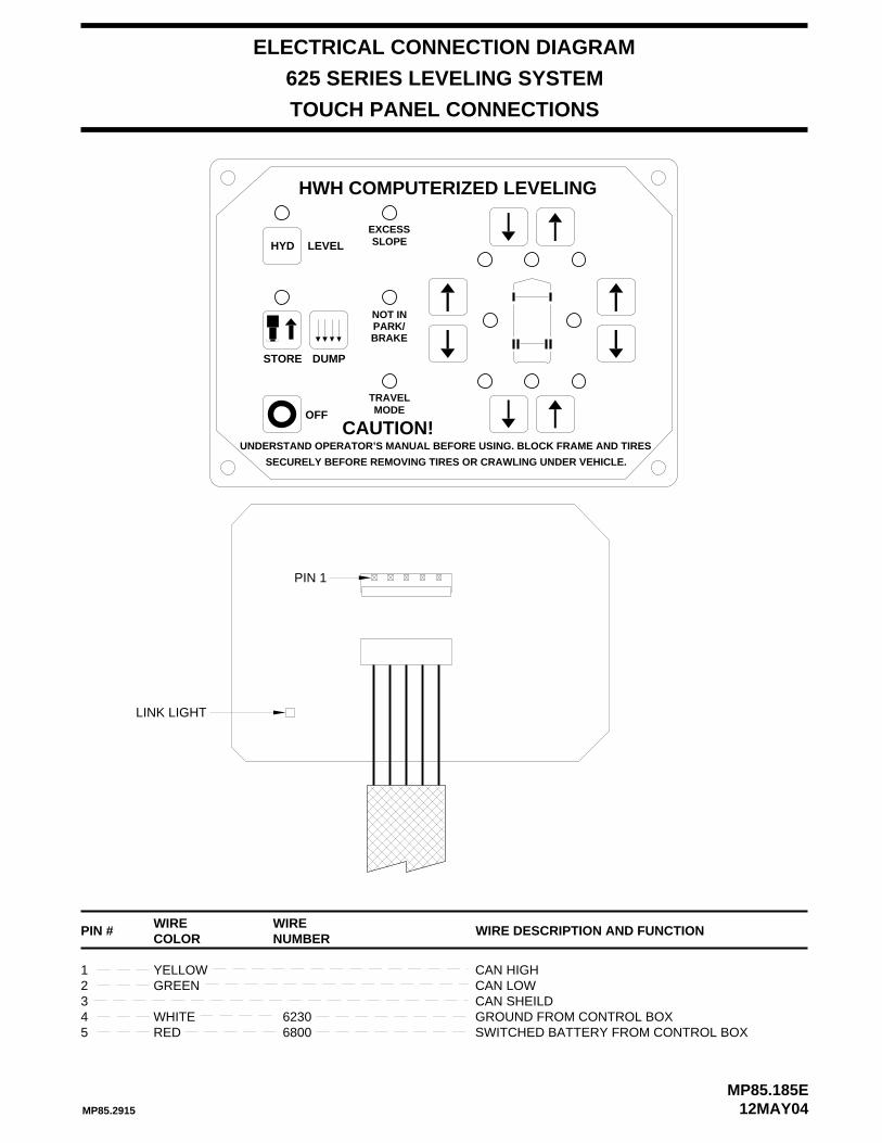
ELECTRICAL CONNECTION DIAGRAM
MP85.185E12MAY04
625 SERIES LEVELING SYSTEM
TOUCH PANEL CONNECTIONS
SECURELY BEFORE REMOVING TIRES OR CRAWLING UNDER VEHICLE.
UNDERSTAND OPERATOR’S MANUAL BEFORE USING. BLOCK FRAME AND TIRES
HWH COMPUTERIZED LEVELING
LEVEL
DUMPSTORE
OFF
HYD
BRAKE
MODETRAVEL
CAUTION!
SLOPEEXCESS
PARK/NOT IN
LINK LIGHT
GROUND FROM CONTROL BOXCAN SHEILDCAN LOWCAN HIGHYELLOW
GREEN
WIRECOLOR
4321
WHITE
PIN #NUMBER
6230
WIRE WIRE DESCRIPTION AND FUNCTION
PIN 1
SWITCHED BATTERY FROM CONTROL BOX6800RED5
MP85.2915

ELECTRICAL CONNECTION DIAGRAM
MP85.185J10OCT13
CN1
CN6
RYR G G RR
PF1
CR5
CR1
CN7
CR2CR10
CR3 CR4CR11
CR6 CR7 CR8 CR9
GN
D
CN3
CN8
PF4
PF3
F10
YYYYRRRR T2
CN9
R R R RLD39 LD36 LD37 LD38
1
12
1
12 8
1
+12
112
LD21LD22LD23LD24LD25LD26LD27LD28
LD
29L
D30
LD
31L
D32
LD
33L
D34
LD
35
AUX
CL CH
(SHIELD)
GND
IGN OUT
GND
IGN
CIRCUIT BOARD CONNECTOR AND PIN LOCATIONS
A32433- 5
PROGRAM CHIP
4 PIN GRAYCONNECTOR
12
3 4
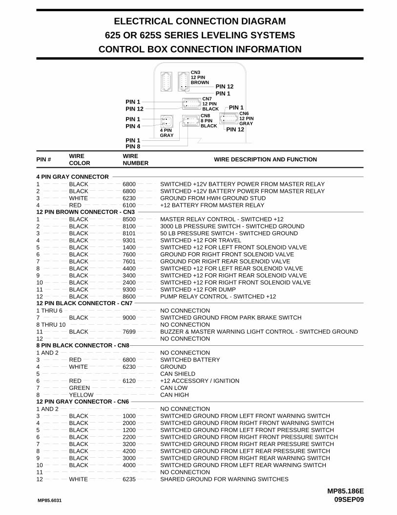
ELECTRICAL CONNECTION DIAGRAM
CONTROL BOX CONNECTION INFORMATION
SWITCHED GROUND FROM RIGHT FRONT WARNING SWITCHSWITCHED GROUND FROM LEFT FRONT WARNING SWITCH
BLACKBLACK
COLORWIRE
12 PIN GRAY CONNECTOR - CN6
43
PIN #NUMBER
20001000
WIRE WIRE DESCRIPTION AND FUNCTION
SWITCHED GROUND FROM LEFT FRONT PRESSURE SWITCHBLACK 12005SWITCHED GROUND FROM RIGHT FRONT PRESSURE SWITCHBLACK 22006SWITCHED GROUND FROM RIGHT REAR PRESSURE SWITCHBLACK 32007
8BLACK 30009
SWITCHED GROUND FROM LEFT REAR WARNING SWITCHBLACK 400010NO CONNECTION11
SWITCHED GROUND FROM RIGHT REAR WARNING SWITCH
625 OR 625S SERIES LEVELING SYSTEMS
SHARED GROUND FOR WARNING SWITCHES6235WHITE12
MASTER RELAY CONTROL - SWITCHED +123000 LB PRESSURE SWITCH - SWITCHED GROUND50 LB PRESSURE SWITCH - SWITCHED GROUNDSWITCHED +12 FOR TRAVELSWITCHED +12 FOR LEFT FRONT SOLENOID VALVEGROUND FOR RIGHT FRONT SOLENOID VALVEGROUND FOR RIGHT REAR SOLENOID VALVESWITCHED +12 FOR LEFT REAR SOLENOID VALVESWITCHED +12 FOR RIGHT REAR SOLENOID VALVESWITCHED +12 FOR RIGHT FRONT SOLENOID VALVESWITCHED +12 FOR DUMPPUMP RELAY CONTROL - SWITCHED +12
76006 BLACK
BLACK
BLACKBLACK
BLACK
12
9
78
1110
8600
7601
34002400
BLACKBLACK
BLACK
12 PIN BROWN CONNECTOR - CN31
4
23
5
81008101
1400
BLACK 4400
CAN LOW+12 ACCESSORY / IGNITIONCAN SHIELDGROUNDSWITCHED BATTERYNO CONNECTION
GREEN
WHITERED
8 PIN BLACK CONNECTOR - CN8
5
7
431 AND 2
62306800
4 PIN GRAY CONNECTORSWITCHED +12V BATTERY POWER FROM MASTER RELAYSWITCHED +12V BATTERY POWER FROM MASTER RELAYGROUND FROM HWH GROUND STUD+12 BATTERY FROM MASTER RELAYRED
WHITEBLACKBLACK
234
16800
61006230
6800
12 PIN BLACK CONNECTOR - CN7
BLACK 8500
NO CONNECTION1 THRU 67 BLACK 9000 SWITCHED GROUND FROM PARK BRAKE SWITCH
NO CONNECTION8 THRU 10BUZZER & MASTER WARNING LIGHT CONTROL - SWITCHED GROUND7699BLACK11NO CONNECTION12
6 RED 6120
YELLOW8 CAN HIGH
NO CONNECTION1 AND 2
BLACK 4200 SWITCHED GROUND FROM LEFT REAR PRESSURE SWITCH
09SEP09MP85.186E
PIN 1PIN 12
PIN 1PIN 8
PIN 1PIN 4
GRAY4 PIN
PIN 1PIN 12
PIN 12
PIN 1
BLACK 9301
BLACK 9300
MP85.6031
12 PINBROWN
CN3
BLACK8 PINCN8 CN6
GRAY12 PIN
BLACK12 PINCN7

CONNECT THIS END TO+12 VOLT IGNITION "ON" POWER
5-15 AMP FUSE
+ _
BUZZER
SEE CONTROL BOXCONNECTION INFORMATION
MASTER LIGHT/BUZZER CONNECTION DIAGRAMMANUAL LEVELING SYSTEMS
625 SERIES LEVELING SYSTEM
MP85.304R27FEB06
A MASTER WARNING INDICATOR SHOULD ALWAYS BE USED. WHEN THE LEVELING SYSTEM HAS STRAIGHT-ACTING JACKS A WARNING BUZZER MUST BE USED.
NOTE: BY SUPPLYING IGNITION POWER TO THE WARNING BUZZER AND LIGHT, AND "ACC" POWER TO THE CONTROL BOX, THE SYSTEM MAY BE OPERATED IN ACCESSORY WITHOUT THE BUZZER SOUNDING. THE NEGATIVE SIGNAL FOR THE WARNING INDICATORS MUST ALWAYS COME FROM THE CONTROL BOX.
PIGTAIL W/DIODEAND IN-LINE FUSE HOLDER - 6121
PIGTAIL PROVIDED - 7699
IGN
ITIO
N
JACKDOWNLIGHT
61117699 6111 7699 7699
WARN LIGHTCONTROL CONTROL
BUZZER
MP85.804R
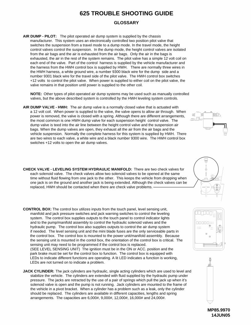
MP85.997014JUN05
625 TROUBLE SHOOTING GUIDE
GLOSSARY
AIR DUMP - PILOT: The pilot operated air dump system is supplied by the chassis
NOTE: Other types of pilot operated air dump systems may be used such as manually controlled valves, but the above described system is controlled by the HWH leveling system controls.
AIR DUMP VALVE - HWH: The air dump valve is a normally closed valve that is actuated with
CHECK VALVE - LEVELING SYSTEM HYDRAULIC MANIFOLD: There are two check valves for
CONTROL BOX: The control box utilizes inputs from the touch panel, level sensing unit,
manufacturer. This system uses an electronically controlled two position pilot valve that switches the suspension from a travel mode to a dump mode. In the travel mode, the height control valves control the suspension. In the dump mode, the height control valves are isolated from the air bags and the air is exhausted from the air bags. Only the air in the bags is exhausted, the air in the rest of the system remains. The pilot valve has a simple 12 volt coil on each end of the valve. Part of the control harness is supplied by the vehicle manufacturer and the harness from the HWH control box is supplied by HWH. There are normally three wires in the HWH harness, a white ground wire, a number 9300 black wire for the dump side and a number 9301 black wire for the travel side of the pilot valve. The HWH control box switches +12 volts to control the pilot valve. When power is supplied to either coil on the pilot valve, the valve remains in that position until power is supplied to the other coil.
a 12 volt coil. When power is supplied to the valve, the valve opens to allow air through. When power is removed, the valve is closed with a spring. Although there are different arrangements, the most common is one HWH dump valve for each suspension height control valve. The dump valve is teed into the air line between the height control valve and the suspension air bags. When the dump valves are open, they exhaust all the air from the air bags and the vehicle suspension. Normally the complete harness for this system is supplied by HWH. There are two wires to each valve, a white wire and a black number 9300 wire. The HWH control box switches +12 volts to open the air dump valves.
each solenoid valve. The check valves allow two solenoid valves to be opened at the same time without fluid flowing from one jack to the other. This keeps the vehicle from dropping when one jack is on the ground and another jack is being extended. Although the check valves can be replaced, HWH should be contacted when there are check valve problems.
manifold and jack pressure switches and jack warning switches to control the leveling system. The control box supplies outputs to the touch panel to control indicator lights and to the pump/manifold assembly to control the hydraulic solenoid valves and the hydraulic pump. The control box also supplies outputs to control the air dump system if needed. The level sensing unit and the mini blade fuses are the only serviceable parts in the control box. The control box is mounted to the power unit/manifold assembly. Because the sensing unit is mounted in the contol box, the orientation of the control box is critical. The sensing unit may need to be programmed if the control box is replaced. (SEE LEVEL SENSING UNIT) The ignition must be in the ON or ACC. position and the park brake must be set for the control box to function. The control box is equipped with LEDs to indicate different functions are operating. A lit LED indicates a function is working,
JACK CYLINDER: The jack cylinders are hydraulic, single acting cylinders which are used to level andstabilize the vehicle. The cylinders are extended with fluid supplied by the hydraulic pump underpressure. The jacks are retracted by the use of a pair of springs which pull the jack up when it’ssolenoid valve is open and the pump is not running. Jack cylinders are mounted to the frame ofthe vehicle in a pivot bracket. When a cylinder has a problem such as a leak, only the cylindershould be replaced. The cylinders are available in different capacities, lengths and springarrangements. The capacities are 6,000#, 9,000#, 12,000#, 16,000# and 24,000#.
A B
B A
LEDs are not turned on to indicate a problem.
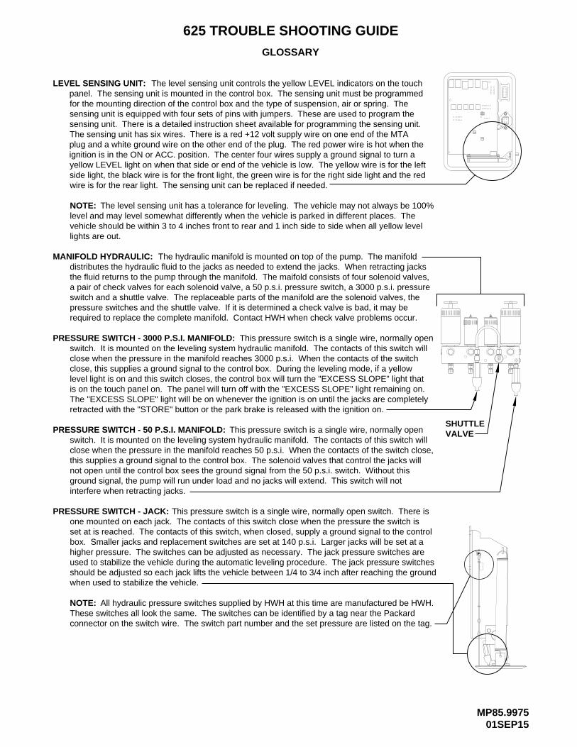
MP85.997501SEP15
625 TROUBLE SHOOTING GUIDE
GLOSSARY
LEVEL SENSING UNIT:
NOTE:
The level sensing unit controls the yellow LEVEL indicators on the touch
The level sensing unit has a tolerance for leveling. The vehicle may not always be 100%level and may level somewhat differently when the vehicle is parked in different places. Thevehicle should be within 3 to 4 inches front to rear and 1 inch side to side when all yellow levellights are out.
MANIFOLD HYDRAULIC: The hydraulic manifold is mounted on top of the pump. The manifolddistributes the hydraulic fluid to the jacks as needed to extend the jacks. When retracting jacksthe fluid returns to the pump through the manifold. The maifold consists of four solenoid valves,a pair of check valves for each solenoid valve, a 50 p.s.i. pressure switch, a 3000 p.s.i. pressureswitch and a shuttle valve. The replaceable parts of the manifold are the solenoid valves, thepressure switches and the shuttle valve. If it is determined a check valve is bad, it may berequired to replace the complete manifold. Contact HWH when check valve problems occur.
PRESSURE SWITCH - 50 P.S.I. MANIFOLD: This pressure switch is a single wire, normally openswitch. It is mounted on the leveling system hydraulic manifold. The contacts of this switch willclose when the pressure in the manifold reaches 50 p.s.i. When the contacts of the switch close,this supplies a ground signal to the control box. The solenoid valves that control the jacks willnot open until the control box sees the ground signal from the 50 p.s.i. switch. Without thisground signal, the pump will run under load and no jacks will extend. This switch will notinterfere when retracting jacks.
PRESSURE SWITCH - 3000 P.S.I. MANIFOLD: This pressure switch is a single wire, normally openswitch. It is mounted on the leveling system hydraulic manifold. The contacts of this switch willclose when the pressure in the manifold reaches 3000 p.s.i. When the contacts of the switchclose, this supplies a ground signal to the control box. During the leveling mode, if a yellowlevel light is on and this switch closes, the control box will turn the "EXCESS SLOPE" light thatis on the touch panel on. The panel will turn off with the "EXCESS SLOPE" light remaining on. The "EXCESS SLOPE" light will be on whenever the ignition is on until the jacks are completely retracted with the "STORE" button or the park brake is released with the ignition on.
PRESSURE SWITCH - JACK: This pressure switch is a single wire, normally open switch. There isone mounted on each jack. The contacts of this switch close when the pressure the switch isset at is reached. The contacts of this switch, when closed, supply a ground signal to the controlbox. Smaller jacks and replacement switches are set at 140 p.s.i. Larger jacks will be set at ahigher pressure. The switches can be adjusted as necessary. The jack pressure switches areused to stabilize the vehicle during the automatic leveling procedure. The jack pressure switchesshould be adjusted so each jack lifts the vehicle between 1/4 to 3/4 inch after reaching the groundwhen used to stabilize the vehicle.
NOTE: All hydraulic pressure switches supplied by HWH at this time are manufactured be HWH.These switches all look the same. The switches can be identified by a tag near the Packardconnector on the switch wire. The switch part number and the set pressure are listed on the tag.
panel. The sensing unit is mounted in the control box. The sensing unit must be programmed for the mounting direction of the control box and the type of suspension, air or spring. The sensing unit is equipped with four sets of pins with jumpers. These are used to program the sensing unit. There is a detailed instruction sheet available for programming the sensing unit. The sensing unit has six wires. There is a red +12 volt supply wire on one end of the MTA plug and a white ground wire on the other end of the plug. The red power wire is hot when the ignition is in the ON or ACC. position. The center four wires supply a ground signal to turn a yellow LEVEL light on when that side or end of the vehicle is low. The yellow wire is for the left side light, the black wire is for the front light, the green wire is for the right side light and the red wire is for the rear light. The sensing unit can be replaced if needed.
SHUTTLEVALVE

MP85.998010SEP07
625 TROUBLE SHOOTING GUIDE
GLOSSARY
PUMP: The hydraulic pump supplies fluid to extend the jacks and operate any HWH slidemechanisms. The pump is turned with a +12 volt motor. (Some systems may use a +24 voltmotor) The motor is a replaceable part. The pump motor is internally grounded. This requiresthe pump/manifold assembly to have a good frame ground through the mounting of the assembly.This may require a separate ground cable, minimum size #2, to supply the necessary ground forthe assembly. The oil level in the pump reservoir should be checked with all HWH cylinders,leveling jacks and/or slides retracted. The oil level should be (1) inch down from the top of thereservoir fill hole. The pump should not run when the leveling jacks are being retracted. Thepump motor does not have thermal protection built into the motor. The correct pump pressureshould be 3500 p.s.i. When checking the pump pressure, the minimum pressure should be3300 p.s.i. and the maximum pressure should be 3600 p.s.i. The pump reservoir is equippedwith a breather cap/dipstick that has a 1/4 inch nut driver in the end of the dipstick to manuallyopen solenoid valves with valve release nuts. The reservoir has to be vented and should neverbe plugged tight.
RELAY - MASTER: The master relay is a continuos duty, normally open, four post relay that consistsof one pair of contacts and a coil. The contacts are used to switch +12 volts to the pump relayand to the control box. Power in and power out on the contacts can be reversed. The coil is a+12 coil. There is a small post on the relay for each side of the coil. Either post can be +12 voltswith the other post being ground. The control box switches +12 volts to turn the relay on. Withthe relay turned on, the contacts will close supplying +12 volts to the pump relay and the controlbox. With the relay off, there should be power on one of the large posts only. With the relay on,the voltage on both large posts should be the same. With the relay off, both sides of the relaycoil, the small posts, should show a ground. With the relay on, one small post should show +12volts, the other small post should show ground. If the ground is missing, both small posts willshow +12 volts. The master relay will be on whenever the POWER ON light on the touch panelis on or while a room control switch is being pushed to EXTEND or RETRACT.
RELAY - PUMP: The pump relay is an intermittent duty, normally open, four post relay that consistsof one pair of contacts and a coil. The contacts are used to switch +12 volts to the pump motor.Power in and power out on the contacts can be reversed. The coil is a +12 coil. There is a smallpost on the relay for each side of the coil. Either post can be +12 volts with the other post beingground. The control box switches +12 volts to turn the relay on. With the relay turned on, thecontacts will close supplying +12 volts to the pump motor. With the relay off, there should bepower on one of the large posts only. With the relay on, the voltage on both large posts shouldbe the same. With the relay off, both sides of the relay coil, the small posts, should show aground. With the relay on, one small post should show +12 volts, the other small post shouldshow ground. If the ground is missing, both small posts will show +12 volts.
SHUTTLE VALVE: The shuttle valve is located on the leveling system hydraulic manifold. (SeeMANIFOLD HYDRAULIC) Fluid flows from the pump to the manifold, through a fitting on top of the manifold, through a U shaped tube to a fitting on top of the shuttle valve, then into the manifold to extend the jacks. The fluid flows from the manifold through the shuttle valve back to the pump when retracting the jacks. The shuttle valve is a hydraulically actuated valve. When the pump is running, the shuttle valve shifts to allow the the fluid into the manifold. At the same time, the shuttle valve closes the path for fluid return to the pump. It takes approximately 800 p.s.i. to shift the shuttle valve. When the pump shuts off, the shuttle valve should shift back to the off position. This will allow fluid to flow from the manifold to the pump when the jacks are retracted. The shuttle valve is a replaceable part.

MP85.998510SEP07
625 TROUBLE SHOOTING GUIDE
GLOSSARY
TOUCH PANEL: The touch panel supplies operational information to the control box. The touch panel receives information from the control box to turn touch panel indicator lights on.See the CONTROL IDENTIFICATION page for the leveling system touch panel to obtain infor-mation about the buttons and lights on the touch panel. There is only one cable that plugs intothe touch panel. There is a small pulsating light on the back of the touch panel called the linklight. The link light should pulsate dimly anytime the ignition is on.
WARNING SWITCH: STRAIGHT-ACTING JACK --- This warning switch is a two wire, normally closed, magnetic switch. The switch mounts in the center of the top of the jack cylinder. There is a magnet inside the jack rod. When the jack is retracted, the magnet is close to the switch. This opens the contacts of the switch. When the jack extends between 1/4 and 1/2 inch, the contacts of the switch close. One of the switch wires supplies a ground to the switch. The other wire carries a ground signal to the control box when the switch is closed. (Jack extended) The control box then turns on the appropriate red WARNING light
KICK-DOWN JACK --- This warning switch is a two wire switch. Inside the
on the touch panel.
switch are two contacts and a steel ball. The switch mounts to the pivot point of the jackcylinder at about a 45 degree angle to the cylinder. When the jack is in the vertical position,the wires of the switch should point to the ground. The steel ball will roll into the contacts,closing the circuit. One wire supplies a ground to the switch, the other wire carries a groundsignal to the control box when the jack is in the vertical position and the steel ball is shortingthe contacts together. The control box then turns on the appropriate red WARNING light onthe touch panel. When the jack is in the horizontal position, the ball rolls away form the contacts, opening the circuit. This turns the red WARNING lights off.
CAUTION!
SECURELY BEFORE REMOVING TIRES OR CRAWLING UNDER VEHICLE.UNDERSTAND OPERATOR’S MANUAL BEFORE USING. BLOCK FRAME AND TIRES
HWH COMPUTERIZED LEVELINGR
ON
OFF
AUTO
STORE
MODETRAVEL
PARK/BRAKE
NOT IN
SLOPEEXCESS
BA
All three valves have two wires for the coil of the valve. The control box switches +12 valve is different making the flow rate of the valve different and non-interchangeable. The large valves are interchangeable. The small valve orifice size in the end of the release nut. The small valve has a valve release nut to open the valve manually. of the large valves has a t-handle to open the valve manually the other has a valve coil. There are two large valves, 2.25 inches, and a small valve, 1.50 inches. One the coil of the valve. A spring closes the valve when +12 volts is removed from the All three valves are normally closed. The valve opens when +12 volts is supplied to
There are three different solenoid valves at this time.
volts to the valves. If a valve will not open with a minimum of 9 volts between the two
SOLENOID VALVE HYDRAULIC: 2.25" 1.50"
WARNING SWITCH:
wires of the valve, with the valve plugged in, the valve needs to be replaced. If replacing the o-rings for a solenoid valve use only 0-rings supplied by HWH.
2.25"LARGE LARGE SMALL
NUT"T" HANDLE NUT
Top Related