


Languages
Pages
Legal

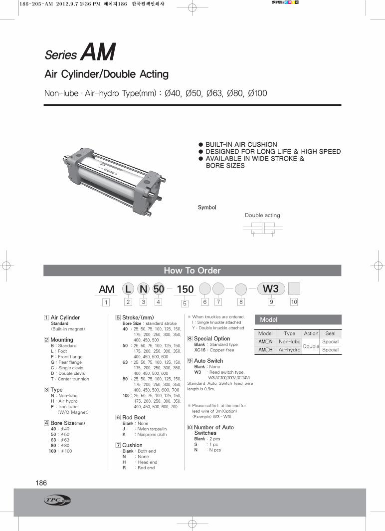
SeriesAMAir Cylinder/Double Acting
Non-lube·Air-hydro Type(mm) : Ø40, Ø50, Ø63, Ø80, Ø100
186
1⃞Air CylinderStandard(Built-in magnet)
2⃞MountingB : StandardL : FootF : Front flangeG : Rear flangeC : Single clevisD : Double clevisT : Center trunnion
3⃞ TypeN : Non-lubeH : Air-hydroF : Iron tube(W/O Magnet)
4⃞Bore Size(mm)40 : ф4050 : ф5063 : ф63 80 : ф80100 : ф100
5⃞Stroke/(mm)Bore Size : standard stroke40 : 25, 50, 75, 100, 125, 150,
175, 200, 250, 300, 350,400, 450, 500
50 : 25, 50, 75, 100, 125, 150,175, 200, 250, 300, 350,400, 450, 500, 600
63 : 25, 50, 75, 100, 125, 150,175, 200, 250, 300, 350,400, 450, 500, 600
80 : 25, 50, 75, 100, 125, 150,175, 200, 250, 300, 350,400, 450, 500, 600, 700
100 : 25, 50, 75, 100, 125, 150,175, 200, 250, 300, 350,400, 450, 500, 600, 700
6⃞Rod BootBlank : NoneJ : Nylon tarpaulinK : Neoprene cloth
7⃞CushionBlank : Both endN :NoneH : Head endR : Rod end
※ When knuckles are ordered,
I : Single knuckle attached
Y : Double knuckle attached
8⃞Special OptionBlank : Standard typeXC16 : Copper-free
9⃞Auto SwitchBlank : NoneW3 : Reed switch type,
W3(AC100,200V,DC 24V)Standard Auto Switch lead wire
length is 0.5m.
※ Please suffix L at the end for
lead wire of 3m(Option)
(Example) W3 - W3L
[10]Number of AutoSwitchesBlank : 2 pcsS : 1 pcN : N pcs
●BUILT-IN AIR CUSHION● DESIGNED FOR LONG LIFE & HIGH SPEED● AVAILABLE IN WIDE STROKE &BORE SIZES
Symbol
How To Order
AM1 2 3 4 5 6 9 108
Model Type Action Seal
AM◯N Non-lubeDouble
Special
AM◯H Air-hydro Special
Model
150 W3L N7
50
Double acting
186-205-AM 2012.9.7 2:36 PM 페이지186 한국원색인쇄사
Series AM
187www.TPCpage.com
www.tpcpneumatics.com
ACP
APM
AS
AX
AM2
AM
ALALX
AQ2ADQ2
AJAJM
ABK
AQADQ
ACK1
NSK
AG
NGQ
AGXGX
NP
ADR
AMR
NDM
ARD
NST
AST
ASTH
NLCD
NLCS
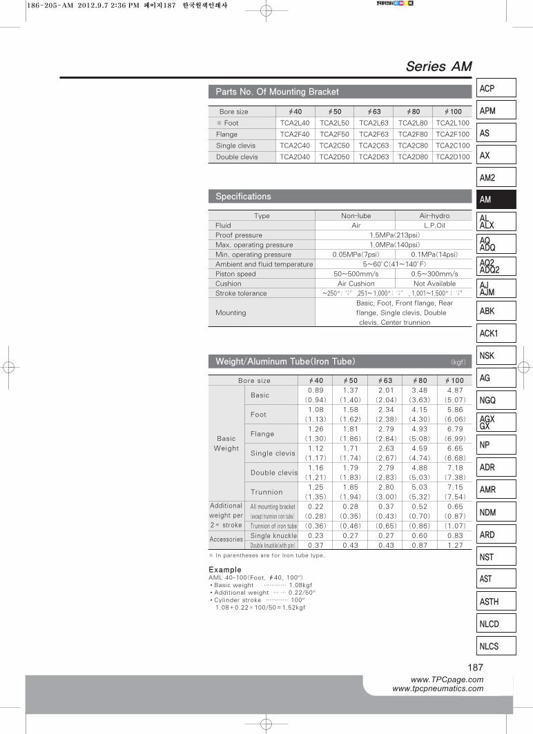
Bore size ф40 ф50 ф63 ф80 ф100
※ Foot TCA2L40 TCA2L50 TCA2L63 TCA2L80 TCA2L100
Flange TCA2F40 TCA2F50 TCA2F63 TCA2F80 TCA2F100
Single clevis TCA2C40 TCA2C50 TCA2C63 TCA2C80 TCA2C100
Double clevis TCA2D40 TCA2D50 TCA2D63 TCA2D80 TCA2D100
Parts No. Of Mounting Bracket
Type Non-lube Air-hydro
Fluid Air L.P.Oil
Proof pressure 1.5MPa(213psi)
Max. operating pressure 1.0MPa(140psi)
Min. operating pressure 0.05MPa(7psi) 0.1MPa(14psi)
Ambient and fluid temperature 5~60°C(41~140°F)
Piston speed 50~500mm/s 0.5~300mm/s
Cushion Air Cushion Not Available
Stroke tolerance ~250st : ,251~`1,000st : , 1,001~1,500st :
Basic, Foot, Front flange, Rear
Mounting flange, Single clevis, Double
clevis, Center trunnion
+1.8+0
+1.4+0
+1.0+0
Specifications
Bore size ф40 ф50 ф63 ф80 ф100
Basic0.89 1.37 2.01 3.48 4.87
(0.94) (1.40) (2.04) (3.63) (5.07)
Foot1.08 1.58 2.34 4.15 5.86
(1.13) (1.62) (2.38) (4.30) (6.06)
Flange1.26 1.81 2.79 4.93 6.79
(1.30) (1.86) (2.84) (5.08) (6.99)
Single clevis1.12 1.71 2.63 4.59 6.65
(1.17) (1.74) (2.67) (4.74) (6.68)
Double clevis1.16 1.79 2.79 4.88 7.18
(1.21) (1.83) (2.83) (5.03) (7.38)
Trunnion1.25 1.85 2.80 5.03 7.15
(1.35) (1.94) (3.00) (5.32) (7.54)
All mounting bracket 0.22 0.28 0.37 0.52 0.65
(except trunnion iron tube) (0.28) (0.35) (0.43) (0.70) (0.87)
Trunnion of iron tube (0.36) (0.46) (0.65) (0.86) (1.07)
Single knuckle 0.23 0.27 0.27 0.60 0.83
Double knuckle(with pin) 0.37 0.43 0.43 0.87 1.27
Weight/Aluminum Tube(Iron Tube)
※ In parentheses are for lron tube type.
ExampleAML 40-100(Foot, ф40, 100st)•Basic weight ………… 1.08kgf•Additional weight … … 0.22/50st
•Cylinder stroke ………… 100st
1.08+0.22×100/50=1.52kgf
(kgf)
Basic
Weight
Additional
weight per
2〃 stroke
Accessories
186-205-AM 2012.9.7 2:36 PM 페이지187 한국원색인쇄사
Series AM
188
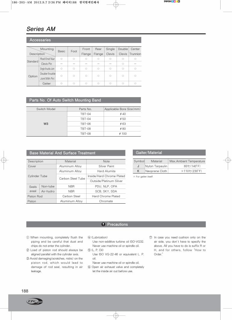
Description Material Note
Cover Aluminum Alloy Silver Paint
Aluminum Alloy Hard Alumite
Cylinder TubeCarbon Steel Tube
Inside/Hard Chrome Plated
Outside/Platinum Silver
Seals
areal
Non-lube
Air-hydro
NBR
NBR
Carbon Steel
Aluminum Alloy
PDU, NLP, OPA
SCB, SKY, SDA
Hard Chrome Plated
Chromate
Piston Rod
Piston
Base Material And Surface Treatment
Precautions
MountingBasic Foot
Front Rear Single Double Center
Description Flange Flange Clevis Clevis Trunnion
StandardRod End Nut ○ ○ ○ ○ ○ ○ ○
Clevis Pin - - - - - ○ -
Single Knuckle Joint ○ ○ ○ ○ ○ ○ ○
Double Knuckle○ ○ ○ ○ ○ ○ ○
Joint(With Pin)
Gaiter ○ ○ ○ ○ ○ ○ ○
Accessaries
※ For gaiter itself
Symbol Material Max.Ambient Temperature
J Nylon Tarpaulin 60℃(140。F)
K Neoprene Cloth ※110℃(230。F)
Gaiter/Material
Switch Model Parts No. Applicable Bore Size(mm)
TBT-04 ф40
TBT-04 ф50
W3 TBT-06 ф63
TBT-08 ф80
TBT-08 ф100
Parts No. Of Auto Switch Mounting Band
Option
① When mounting, completely flush the
piping and be careful that dust and
chips do not enter the cylinder.
② Load of piston rod should always be
aligned parallel with the cylinder axis.
③Avoid damaging(scratches, nicks) on the
piston rod, which would lead to
damage of rod seal, resulting in air
leakage.
④ <Lubrication>
Use non-additive turbine oil ISO-VG32.
Never use machine oil or spindle oil.
⑤ <L. P. Oil>
Use ISO VG-22-46 or equivalent L. P.
oil.
Never use machine oil or spindle oil.
⑥ Open air exhaust valve and completely
let the inside air out before use.
⑦ In case you need cushion only on the
air side, you don’t have to specify the
above. All you have to do is suffix R or
H, and for others, follow “How to
Order.”
186-205-AM 2012.9.7 2:36 PM 페이지188 한국원색인쇄사
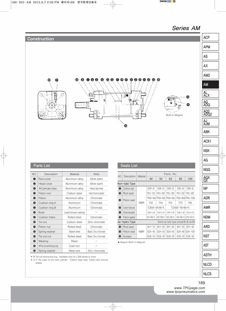
Construction
Series AM
189www.TPCpage.com
www.tpcpneumatics.com
ACP
APM
AS
AX
AM2
AM
ALALX
AQ2ADQ2
AJAJM
ABK
AQADQ
ACK1
NSK
AG
NGQ
AGXGX
NP
ADR
AMR
NDM
ARD
NST
AST
ASTH
NLCD
NLCS
NO. Description Material40 50 63 80 100
Non-lube Type
Cushion seal DSM-20 DSM-25 DSM-25 DSM-30 DSM-35
Rod seal PDU-16Z PDU-20Z PDU-20Z PDU-25Z PDU-30Z
Piston sealTPSA-40A TPSA-50A TPSA-63A TPSA-80A TPSA-100A
P34 P44 P53 P70 P90
Cushion Valve seal
(21) Cylinder tube gasket TC2A040-16-1486 TC2A050-16-1487 TC2A063-16-1488 TC2A080-16-1489 TC2A100-16-1490
(22) Piston gasket CA40-1606k-PL CA63-1608k-PL CA63-1608k-PL CA80-1609k-PL CA100-1610k-PL
Air-hydro Type
Rod seal SKY-16 SKY-20 SKY-20 SKY-25 SKY-30
Piston seal NBR SDA-40 SDA-50 SDA-63 SDA-80 SDA-100
(23) Scraper SCB-16 SCB-20 SCB-20 SCB-25 SCB-30
Seals List
NO. Description Material Note
❶ Rod cover Aluminum alloy Silver paint
❷ Head cover Aluminum alloy Silver paint
❸ ※Cylinder tube Aluminum alloy Hard alumite
❹ Piston rod Carbon steel Hard chrome plated
❺ Piston Aluminum alloy Chromate
❻ Cushion ring A Aluminum Chromate
❼ Cushion ring B Aluminum Chromate
❽ Bush Lead bronze casting -
❾ Cushion Valve Rolled steel Chromate
❿ Tie rod Carbon steel Zinc chromate
Piston nut Rolled steel Chromate
Spring washer Steel wire Black Zinc chromate
Tie rod nut Rolled steel Black Zinc chromate
Wearing Resin -
(24) ※Tie rod reinforcing ring Cast iron -
(25) Spring washer Steel wire Zinc chromate
Parts List
※(24)Tie rod reinforcing ring : Available only for 1,000 stroke or more.
※③ In the case of lron tube cylinder : Carbon steel tube, inside hard chrome
plated.
Same as lube type except⒕,⒖ and(23)
Parts. No.
❾
(24)
❽ ❶ ❹ ❸ ❻ (22) ❺ ❼ (21) ❷ (25) ❿
NBR
TC2A040-16A1486-PL TC2A063-16A1488-PL
Built-in Magnet
★Magnet (Built-in Magnet)
★
186-205-AM 2012.9.7 2:36 PM 페이지189 한국원색인쇄사
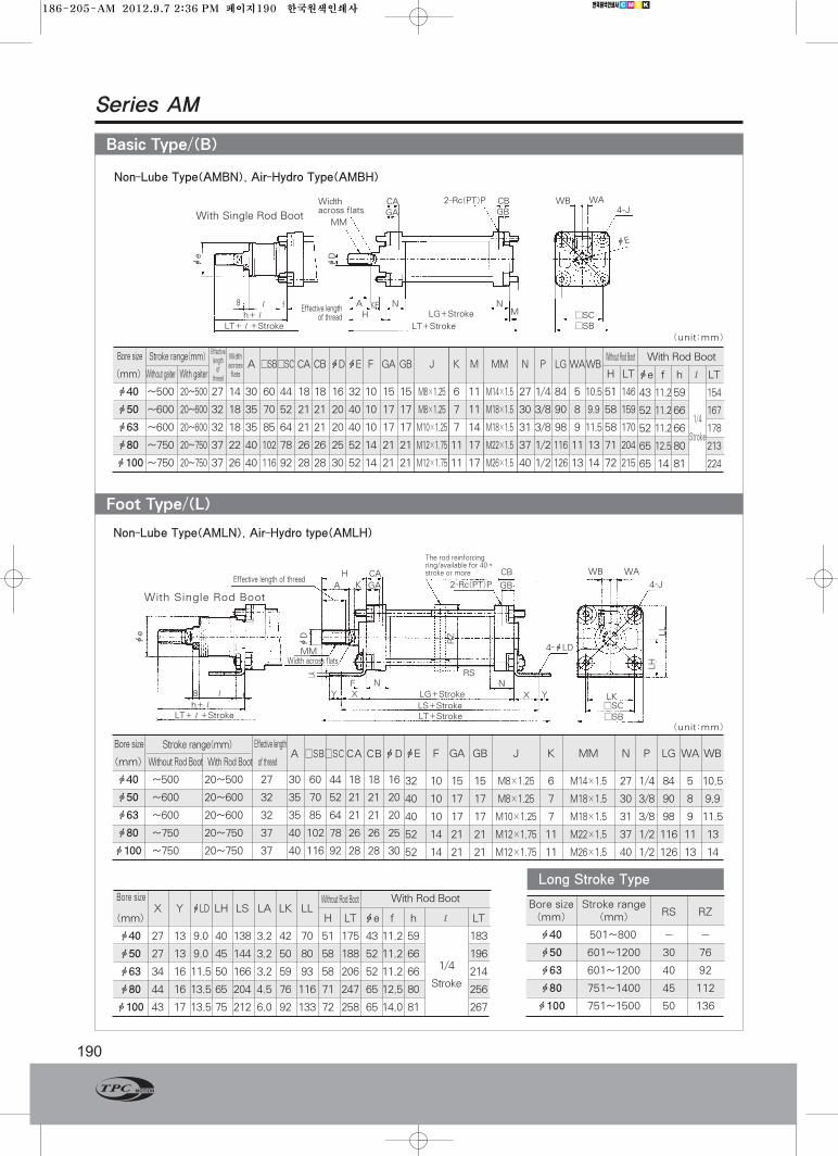
Series AM
190
Foot Type/(L)
Basic Type/(B)
Bore size
(mm) Without Rod Boot With Rod Boot of thread
ф40 ~500 20~500 27 30 60 44 18 18 16
ф50 ~600 20~600 32 35 70 52 21 21 20
ф63 ~600 20~600 32 35 85 64 21 21 20
ф80 ~750 20~750 37 40 102 78 26 26 25
ф100 ~750 20~750 37 40 116 92 28 28 30
Bore sizeX Y фLD LH LS LA LK LL
(mm) H LT фe f h ℓ LT
ф40 27 13 9.0 40 138 3.2 42 70 51 175 43 11.2 59 183
ф50 27 13 9.0 45 144 3.2 50 80 58 188 52 11.2 66 196
ф63 34 16 11.5 50 166 3.2 59 93 58 206 52 11.2 66 214
ф80 44 16 13.5 65 204 4.5 76 116 71 247 65 12.5 80 256
ф100 43 17 13.5 75 212 6.0 92 133 72 258 65 14.0 81 267
Bore size Stroke rangeRS RZ(mm) (mm)
ф40 501~800` - -
ф50 601~1200 30 76
ф63 601~1200 40 92
ф80 751~1400 45 112
ф100 751~1500 50 136
Non-Lube Type(AMBN), Air-Hydro Type(AMBH)
Bore sizeA □SB□SC CA CB фDфE F GA
(mm) Without gaiter With gaiter
ф40 ~500 20~500 27 14 30 60 44 18 18 16 32 10 15
ф50 ~600 20~600 32 18 35 70 52 21 21 20 40 10 17
ф63 ~600 20~600 32 18 35 85 64 21 21 20 40 10 17
ф80 ~750 20~750 37 22 40 102 78 26 26 25 52 14 21
ф100~750 20~750 37 26 40 116 92 28 28 30 52 14 21
GB J K M MM N P LGWAWBH LT
15 M8×1.25 6 11 M14×1.5 27 1/4 84 5 10.5 51 146
17 M8×1.25 7 11 M18×1.5 30 3/8 90 8 9.9 58 159
17 M10×1.25 7 14 M18×1.5 31 3/8 98 9 11.5 58 170
21 M12×1.75 11 17 M22×1.5 37 1/2 116 11 13 71 204
21 M12×1.75 11 17 M26×1.5 40 1/2 126 13 14 72 215
фe f h ℓ LT
43 11.259 154
52 11.266 167
52 11.266 178
65 12.580 213
65 14 81 224
(unit:mm)
(unit:mm)
Without Rod Boot With Rod BootStroke range(mm)
фE F GA GB J K MM N P LG WA WB
32 10 15 15 M8×1.25 6 M14×1.5 27 1/4 84 5 10.5
40 10 17 17 M8×1.25 7 M18×1.5 30 3/8 90 8 9.9
40 10 17 17 M10×1.25 7 M18×1.5 31 3/8 98 9 11.5
52 14 21 21 M12×1.75 11 M22×1.5 37 1/2 116 11 13
52 14 21 21 M12×1.75 11 M26×1.5 40 1/2 126 13 14
Stroke range(mm)
With Rod BootWithout Rod Boot
1/4
Stroke
фe
фD
8 Kfℓ AH LG+Stroke
LT+Stroke
N N□SC□SB
M
CA CB WB WA2-Rc(PT)P
GA GB 4-J
фE
Widthacross flats
Effective lengthof thread
MM
LT+ℓ+Strokeh+ℓ
F
With Single Rod Boot
ℓ
H CA CB WB WA
GBA
MMWidth across flats
Effective length of thread2-Rc(PT)P
4-фLD
4-JGA
h+ℓLT+ℓ+Stroke
Effective lengthA □SB□SCCA CBфD
LG+Stroke
RS
The rod reinforcingring/available for 40〃stroke or more
LS+StrokeLT+Stroke
f
FXY
LA
N N
X LK□SC□SB
Y
K
8
фD
LH
LL
RZ
Long Stroke Type
With Single Rod Boot
Non-Lube Type(AMLN), Air-Hydro type(AMLH)
фe
Effectivelengthof
thread
Widthacrossflats
1/4
Stroke
186-205-AM 2012.9.7 2:36 PM 페이지190 한국원색인쇄사
Series AM
191www.TPCpage.com
www.tpcpneumatics.com
ACP
APM
AS
AX
AM2
AM
ALALX
AQ2ADQ2
AJAJM
ABK
AQADQ
ACK1
NSK
AG
NGQ
AGXGX
NP
ADR
AMR
NDM
ARD
NST
AST
ASTH
NLCD
NLCS
Front Flange/(F)
Non-Lube Type(AMFN), Air-Hydro Type(AMFH)
Bore size Effective lengthA B □SB □SCCA CB
(mm) Without Rod Boot With Rod Boot of thread
ф40 ~800 20~800 27 30 71 60 44 18 18
ф50 ~1,000 20~1,000 32 35 81 70 52 21 21
ф63 ~1,000 20~1,000 32 35 101 85 64 21 21
ф80 ~1,000 20~1,000 37 40 119 102 78 26 26
ф100 ~1,000 20~1,000 37 40 133 116 92 28 28
Bore sizeFH фFD FT FK FL FM
(mm) H LT ★фd фe f h ℓ LT
ф40 60 9.0 12 80 42 100 51 146 52 43 15 59 154
ф50 70 9.0 12 90 50 110 58 159 58 52 15 66 167
ф63 86 11.5 15 105 59 130 58 170 58 52 17.5 66 178
ф80 10213.5 18 130 76 160 71 204 80 65 21.5 80 213
ф100 11613.5 18 150 92 180 72 215 80 65 21.5 81 224
фD фE GA GB J K M MM N P LG WAWB
16 32 15 15 M8×1.25 6 11 M14×1.5 27 1/4 84 5 10.5
20 40 17 17 M8×1.25 7 11 M18×1.5 30 3/8 90 8 9.9
20 40 17 17 M10×1.25 7 14 M18×1.5 31 3/8 98 9 11.5
25 52 21 21 M12×1.75 11 17 M22×1.5 37 1/2 116 11 13
30 52 21 21 M12×1.75 11 17 M26×1.5 40 1/2 126 13 14
Stroke range(mm)
With Rod BootWithout Rod Boot
1/4
Stroke
★ Hole diameter of Rod Boot to mount Air-cylindershould be larger than the outside diameter ofgaiter mounting bracket фd.
Bore sizeфFD FT FK FL FM RS RZ
(mm) H LT ★фe f h ℓ LT
ф50 9.0 20 120 58 144 30 76 67 163 52 19 66 162
ф63 11.5 23 140 64 170 40 92 71 179 52 19 66 174
ф80 13.5 28 164 84 198 45 112 87 215 65 21 80 208
ф100 13.5 29 180 100 220 50 136 89 227 65 21 81 219
With Rod BootWithout Rod Boot
1/4
Stroke
★ Hole diameter of rod boot to mount Air-cylinder should be larger than the outsidediameter of rod boot mounting bracket фe.
With Single Rod Boot
8 ℓ Kf AH
N N
WB
ΦE
WA 4-J4-фFD
MLG+Stroke
□SC□SBFKFMLT+Stroke
Effective lengthof thread
h+ℓ
MM
CA
GACBGB
LT+ℓ+Stroke
Widthacross flats
2-Rc(PT)P
With Single Gaiter
фE
фe
h+ℓLT+ℓ+Stroke
fℓ8FKFM
□SB□SC
4-J4-фFD
FL B фD
MM
AH
K
2-Rc(PT)P
LG+StrokeLT+Stroke
Bore size Stroke range Effective lengthA B □SB □SC фD фE
(mm) (mm) of thread
ф50 1,001~1,200 32 35 88 70 52 20 40
ф63 1,001~1,200 32 35 105 85 64 20 40
ф80 1,001~1,400 37 40 124 102 78 25 52
ф100 1,001~1,500 37 40 140 116 92 30 52
GA GB J K M MM N P LG WA WB
17 17 M8×1.25 7 6 M18×1.5 30 3/8 90 8 9.9
17 17 M10×1.25 7 10 M18×1.5 31 3/8 98 9 11.5
21 21 M12×1.75 11 12 M22×1.5 37 1/2 116 11 13
21 21 M12×1.75 11 12 M26×1.5 40 1/2 126 13 14
N M
GB
RS
□RZ
N
GAFT
фe
фD
фd BFHFL
Effective lengthof thread
Long Stroke(1001 Stroke or more)
Widthacross flats
(unit:mm)
(unit:mm)
186-205-AM 2012.9.7 2:36 PM 페이지191 한국원색인쇄사
Series AM
192
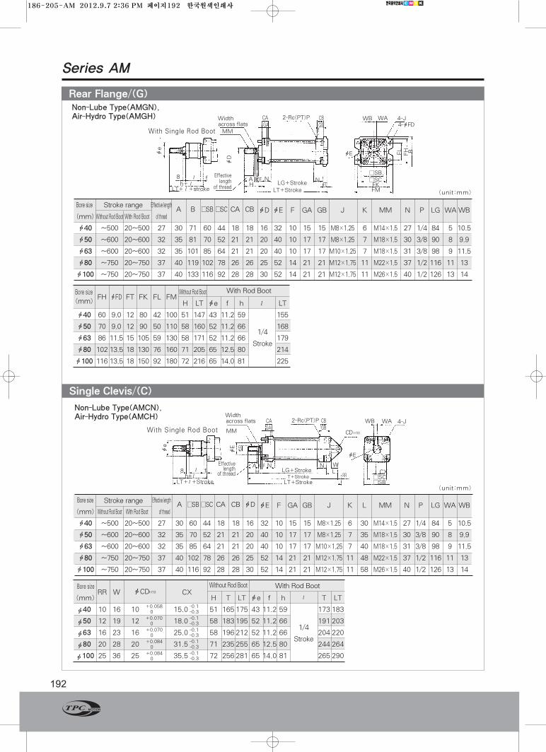
Single Clevis/(C)
Rear Flange/(G)
Bore size Effective lengthA B □SB □SC CA CB
(mm) Without Rod Boot With Rod Boot of thread
ф40 ~500 20~500 27 30 71 60 44 18 18
ф50 ~600 20~600 32 35 81 70 52 21 21
ф63 ~600 20~600 32 35 101 85 64 21 21
ф80 ~750 20~750 37 40 119 102 78 26 26
ф100 ~750 20~750 37 40 133 116 92 28 28
Bore sizeFH фFD FT FK FL FM
(mm) H LT фe f h ℓ LT
ф40 60 9.0 12 80 42 100 51 147 43 11.2 59 155
ф50 70 9.0 12 90 50 110 58 160 52 11.2 66 168
ф63 86 11.5 15 105 59 130 58 171 52 11.2 66 179
ф80 10213.5 18 130 76 160 71 205 65 12.5 80 214
ф100 11613.5 18 150 92 180 72 216 65 14.0 81 225
фD фE F GA GB J K MM N P LG WAWB
16 32 10 15 15 M8×1.25 6 M14×1.5 27 1/4 84 5 10.5
20 40 10 17 17 M8×1.25 7 M18×1.5 30 3/8 90 8 9.9
20 40 10 17 17 M10×1.25 7 M18×1.5 31 3/8 98 9 11.5
25 52 14 21 21 M12×1.75 11 M22×1.5 37 1/2 116 11 13
30 52 14 21 21 M12×1.75 11 M26×1.5 40 1/2 126 13 14
Stroke range
With Rod BootWithout Rod Boot
1/4
Stroke
Bore size Effective lengthA □SB□SC CA CB фD
(mm) Without Rod Boot With Rod Boot of thread
ф40 ~500 20~500 27 30 60 44 18 18 16
ф50 ~600 20~600 32 35 70 52 21 21 20
ф63 ~600 20~600 32 35 85 64 21 21 20
ф80 ~750 20~750 37 40 102 78 26 26 25
ф100 ~750 20~750 37 40 116 92 28 28 30
фE F GA GB J K L MM N P LG WA WB
32 10 15 15 M8×1.25 6 30 M14×1.5 27 1/4 84 5 10.5
40 10 17 17 M8×1.25 7 35 M18×1.5 30 3/8 90 8 9.9
40 10 17 17 M10×1.25 7 40 M18×1.5 31 3/8 98 9 11.5
52 14 21 21 M12×1.75 11 48 M22×1.5 37 1/2 116 11 13
52 14 21 21 M12×1.75 11 58 M26×1.5 40 1/2 126 13 14
Stroke range
Bore sizeRR W
(mm) H T LT фe f h ℓ T LT
ф40 10 16 10 15.0 51 165175 43 11.2 59 173183
ф50 12 19 12 18.0 58 183195 52 11.2 66 191203
ф63 16 23 16 25.0 58 196212 52 11.2 66 204220
ф80 20 28 20 31.5 71 235255 65 12.5 80 244264
ф100 25 36 25 35.5 72 256281 65 14.0 81 265290
With Rod BootWithout Rod Boot
1/4
Stroke
-0.1-0.3
+0.0580
+0.0700
+0.0700
+0.0840
+0.0840
-0.1-0.3-0.1-0.3-0.1-0.3-0.1-0.3
фCDH10 CX
фe
□SB
фD
8 ℓ KFf AH
NFT
N
WB WA 4-J4-фFD
фE
фE
LG+Stroke□SCFKFMLT+Stroke
Effectivelength
of threadh+ℓ
MM
CAGA
CBGB
LT+ℓ+stroke
Widthacross flats
2-Rc(PT)P
BFHFL
фe
ℓFK
fAH
WL
RR
N N
WB WA 4-J
CD H10
фEфD
LG+StrokeT+Stroke □SC
□SB
CX
LT+Stroke
Effectivelength
of threadh+ℓ8
MM
CAGA
CBGB
LT+ℓ+Stroke
Widthacross flats 2-Rc(PT)P
With Single Rod Boot
With Single Rod Boot
Non-Lube Type(AMGN),Air-Hydro Type(AMGH)
Non-Lube Type(AMCN),Air-Hydro Type(AMCH)
(unit:mm)
(unit:mm)
186-205-AM 2012.9.7 2:36 PM 페이지192 한국원색인쇄사
Series AM
193www.TPCpage.com
www.tpcpneumatics.com
ACP
APM
AS
AX
AM2
AM
ALALX
AQ2ADQ2
AJAJM
ABK
AQADQ
ACK1
NSK
AG
NGQ
AGXGX
NP
ADR
AMR
NDM
ARD
NST
AST
ASTH
NLCD
NLCS
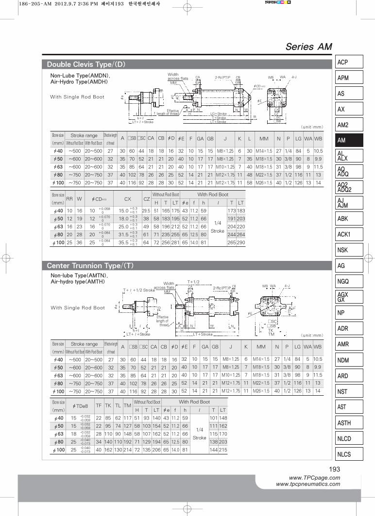
Double Clevis Type/(D)
Bore sizeTF TK TL TM
(mm) H T LT фe f h ℓ T LT
ф40 15 22 85 62 117 51 93 140 43 11.2 59 101148
ф50 15 22 95 74 127 58 103 154 52 11.2 66 111162
ф63 18 28 110 90 148 58 107 162 52 11.2 66 115170
ф80 25 34 140 110192 71 129 194 65 12.5 80 138203
ф100 25 40 162 130214 72 135 206 65 14.0 81 144215
Non-lube Type(AMTN), Air-hydro type(AMTH)
Bore size Effecitive lengthA □SB□SC CA CB фD
(mm) Without Rod Boot With Rod Boot of thread
ф40 ~500 20~500 27 30 60 44 18 18 16
ф50 ~600 20~600 32 35 70 52 21 21 20
ф63 ~600 20~600 32 35 85 64 21 21 20
ф80 ~750 20~750 37 40 102 78 26 26 25
ф100 ~750 20~750 37 40 116 92 28 28 30
фE F GA GB J K L MM N P LG WA WB
32 10 15 15 M8×1.25 6 30 M14×1.5 27 1/4 84 5 10.5
40 10 17 17 M8×1.25 7 35 M18×1.5 30 3/8 90 8 9.9
40 10 17 17 M10×1.25 7 40 M18×1.5 31 3/8 98 9 11.5
52 14 21 21 M12×1.75 11 48 M22×1.5 37 1/2 116 11 13
52 14 21 21 M12×1.75 11 58 M26×1.5 40 1/2 126 13 14
Stroke range
Bore sizeRR W
(mm) H T LT фe f h ℓ T LT
ф40 10 16 10 15.0 29.5 51 165 175 43 11.2 59 173183
ф50 12 19 12 18.0 38 58 183 195 52 11.2 66 191203
ф63 16 23 16 25.0 49 58 196 212 52 11.2 66 204220
ф80 20 28 20 31.5 61 71 235 255 65 12.5 80 244264
ф100 25 36 25 35.5 64 72 256 281 65 14.0 81 265290
With Rod BootWithout Rod Boot
1/4
Stroke
+0.3+0.1
+0.0580
-0.032-0.059-0.032-0.059-0.032-0.059-0.040-0.073-0.040-0.073
+0.0700
+0.0700
+0.0840
+0.0840
+0.3+0.1+0.3+0.1+0.3+0.1+0.3+0.1
фCDH10 CX CZ
Bore size Effiective lengthA □SB □SC CA CB фD
(mm) Without Rod Boot With Rod Boot of thread
ф40 ~500 20~500 27 30 60 44 18 18 16
ф50 ~600 20~600 32 35 70 52 21 21 20
ф63 ~600 20~600 32 35 85 64 21 21 20
ф80 ~750 20~750 37 40 102 78 26 26 25
ф100 ~750 20~750 37 40 116 92 28 28 30
фE F GA GB J K MM N P LG WA WB
32 10 15 15 M8×1.25 6 M14×1.5 27 1/4 84 5 10.5
40 10 17 17 M8×1.25 7 M18×1.5 30 3/8 90 8 9.9
40 10 17 17 M10×1.25 7 M18×1.5 31 3/8 98 9 11.5
52 14 21 21 M12×1.75 11 M22×1.5 37 1/2 116 11 13
52 14 21 21 M12×1.75 11 M26×1.5 40 1/2 126 13 14
Stroke range
With Rod BootWithout Rod BootфTDe8
1/4
Stroke
Center Trunnion Type/(T)
8
фe
фE
фD
h+ℓℓ
Widthacross flats
f
MM
A KF N N
2-Rc(PT)P
фCD H10
фE
фE
LRR
W
WB WA
CX
4-J
CZ□SC□SB
H LG+StrokeT+StrokeLT+Stroke
CB
GB
CA
GA
8
LT+ℓ+Stroke
Effectivelength of thread
With Single Rod Boot
With Single Rod Boot
T+ℓ+1/2 Stroke2-Rc(PT)PCA CB WB WA 4-J
фTDe8
фDфe
TL
TF
LT+StrokeLT+ℓ+Stroke
Effectivelength ofthread
Widthacross flats
h+lℓ f A
HK N
MM
F N
□SC□SBTKTM
GBGA
Non-Lube Type(AMDN), Air-Hydro Type(AMDH)
T+1/2
(unit:mm)
(unit:mm)
186-205-AM 2012.9.7 2:36 PM 페이지193 한국원색인쇄사
Series AM
194
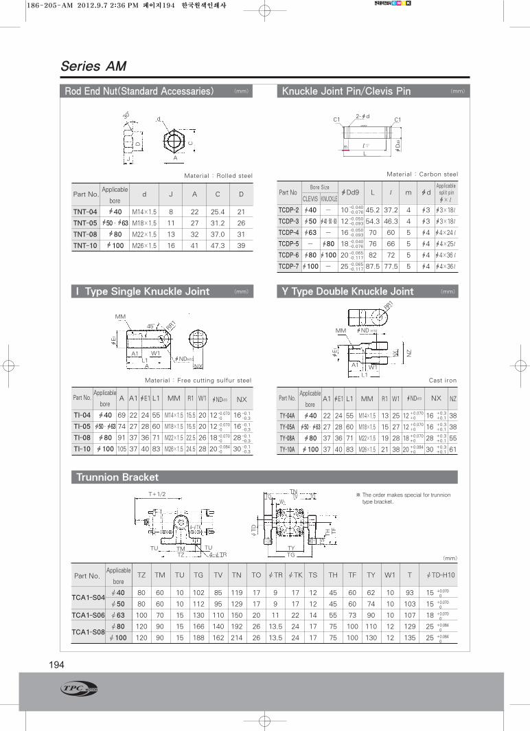
Knuckle Joint Pin/Clevis PinRod End Nut(Standard Accessaries)
Part No.Applicable
A1 фE1 L1 MM R1 W1 NZbore
TY-04A ф40 22 24 55 M14×1.5 13 25 12 16 38
TY-05A ф50·ф63 27 28 60 M18×1.5 15 27 12 16 38
TY-08A ф80 37 36 71 M22×1.5 19 28 18 28 55
TY-10A ф100 37 40 83 M26×1.5 21 38 20 30 61
I Type Single Knuckle Joint
Trunnion Bracket
Y Type Double Knuckle Joint
Part No.Applicable
d J A C Dbore
TNT-04 ф40 M14×1.5 8 22 25.4 21
TNT-05 ф50·ф63 M18×1.5 11 27 31.2 26
TNT-08 ф80 M22×1.5 13 32 37.0 31
TNT-10 ф100 M26×1.5 16 41 47.3 39
Material : Rolled steel
Part No.Applicable
A A1 фE1 L1 MM R1 W1bore
TI-04 ф40 69 22 24 55 M14×1.5 15.5 20 12 16
TI-05 ф50·ф63 74 27 28 60 M18×1.5 15.5 20 12 16
TI-08 ф80 91 37 36 71 M22×1.5 22.5 26 18 28
TI-10 ф100 105 37 40 83 M26×1.5 24.5 28 20 30
Part No.Applicable
TZ TM TU TG TV TN TO ØTR ØTK TS TH TF TY W1 T ØTD-H10bore
TCA1-S04Ø40 80 60 10 102 85 119 17 9 17 12 45 60 62 10 93 15
Ø50 80 60 10 112 95 129 17 9 17 12 45 60 74 10 103 15
TCA1-S06 Ø63 100 70 15 130 110 150 20 11 22 14 55 73 90 10 107 18
TCA1-S08Ø80 120 90 15 166 140 192 26 13.5 24 17 75 100 110 12 129 25
Ø100 120 90 15 188 162 214 26 13.5 24 17 75 100 130 12 135 25
-0.1-0.3
-0.1-0.3
-0.1-0.3
-0.1-0.3
-0.070-0
-0.070-0
-0.070-0
-0.084-0
+0.3+0.1
+0.3+0.1
+0.3+0.1
+0.3+0.1
+0.070+0
+0.070+0
+0.070+0
+0.084+0
фNDH10 NX фNDH10 NX
material : Cast iron
30。
D C
J A
d
MM
45°
A1 W1L1A NX
RR1
RR1
фNDH10
MM
(mm) (mm)
(mm) (mm)
(mm)
L1
A1 W1
фND H10фE1
NX
NZ
TU
4-ØTK
TN※The order makes special for trunniontype bracket.
TH
ØTD
TO TOTVW1
TF
TYTG4-ØTR
TMTZ
TU
T+1/2
TS
фE1
+0.0700
+0.0700
+0.0700
+0.0840
+0.0840
Material : Free cutting sulfur steel
Part No фDd9 L ℓ m фdCLEVIS KNUCKLE
TCDP-2 ф40 - 10 45.2 37.2 4 ф3 ф3×18ℓ
TCDP-3 ф50 ф40·50·63 12 54.3 46.3 4 ф3 ф3×18ℓ
TCDP-4 ф63 - 16 70 60 5 ф4 ф4×24ℓ
TCDP-5 - ф80 18 76 66 5 ф4 ф4×25ℓ
TCDP-6 ф80 ф100 20 82 72 5 ф4 ф4×36ℓ
TCDP-7 ф100 - 25 87.5 77.5 5 ф4 ф4×36ℓ
Material : Carbon steel
Bore Size
-0.040-0.076
-0.050-0.093
-0.050-0.093
-0.040-0.076
-0.065-0.117
-0.065-0.117
2-фdC1C1
L
ℓ+0.20m
фDd9
ф×ℓ
Applicablesplit pin
186-205-AM 2012.9.7 2:36 PM 페이지194 한국원색인쇄사

SeriesAMKNon-Rotating Piston Rod Type
Non-lube Type : Ø40, Ø50, Ø63
195www.TPCpage.com
www.tpcpneumatics.com
ACP
APM
AS
AX
AM2
AM
ALALX
AQ2ADQ2
AJAJM
ABK
AQADQ
ACK1
NSK
AG
NGQ
AGXGX
NP
ADR
AMR
NDM
ARD
NST
AST
ASTH
NLCD
NLCS
AMK
●HIGH NON-ROTATING ACCURACY/±0.5°● SAME MOUNTING DIMENSION AS OURSTANDARD TYPE
● AUTO SWITCH CAN BE MOUNTED(TIE ROD MOUNT TYPE)● NON-LUBRICATED OPERATION POSSIBLE
Symbol
How to Order
3 5 6 81 2
L7
Fluid Air
Proof pressure 1.5MPa(213psi)
Max.operating pressure 1.0MPa(140psi)
Min.operating pressure 0.5MPa(7psi)
Ambient and fluid temperature 5~60℃(41~140。F)
Piston speed 50~500mm/s
Cushion Air Cushion
Stroke tolerance ф40:25~500st: , ф50, ф63:25~600st:
Allowable rotational torque ±0.5°
Lubication Not required
Bore size(mm) ф40, ф50, ф63,
Basic, Foot, Front flange,
Rear flange, Single clevis,
Double clevis, Center trunnion
Specification
J4
40 W3
1⃞Non-Rotating Piston-Rod Type Series(Built-in Magnet)
2⃞Mounting
3⃞ Bore Size
4⃞ Stroke
5⃞With Rod Boot
6⃞ Order Made Option
7⃞ Auto Switch
8⃞ Number of Auto Switches
+1.40
Piston Rod cross section
200
Basic, Foot, front flange
Mounting
※For details, please refer to page 186
186-205-AM 2012.9.7 2:36 PM 페이지195 한국원색인쇄사

Series AMK
196
Bore size Effective lengthA □SB□SC CA CB фD
(mm) Without Rod Boot With Rod Boot of thread
ф40 ~500 20~500 27 30 60 44 18 18 16
ф50 ~600 20~600 32 35 70 52 21 21 20
ф63 ~600 20~600 32 35 85 64 21 21 20
фE F GA GB J KA MM N P LG WA WB
32 10 15 15 M8×1.25 14 M14×1.5 27 1/4 84 5 10.5
40 10 17 17 M8×1.25 18 M18×1.5 30 3/8 90 8 9.9
40 10 17 17 M10×1.25 18 M18×1.5 31 3/8 98 9 11.5
Stroke range
Bore size
(mm) H LT фe f h ℓ LT
ф40 51 146 43 11.2 59 154
ф50 58 159 52 11.2 66 167
ф63 58 170 52 11.2 66 178
With Rod BootWithout Rod Boot
1/4
Stroke
фe
фD фE
WA
WB
ℓ8 f
h+ℓ
MM
GA GB
CBN
M
□SC□SBA
HF NCA
4-J
LG+Stroke
LT+Stroke
2-Rc(PT)P
(Unit:mm)
DimensionsacrossflatsKA
LT+ℓ+Stroke
With Single Rod Boot
Effectivelengthof thread
Basic Type(B)
186-205-AM 2012.9.7 2:36 PM 페이지196 한국원색인쇄사
ACP
APM
AS
AX
AM2
AM
ALALX
AQ2ADQ2
AJAJM
ABK
AQADQ
ACK1
NSK
AG
NGQ
AGXGX
NP
ADR
AMR
NDM
ARD
NST
AST
ASTH
NLCD
NLCS
197www.TPCpage.com
www.tpcpneumatics.com
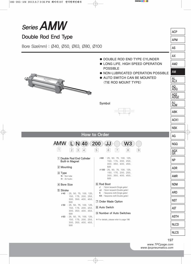
SeriesAMWDouble Rod End Type
Bore Size(mm) : Ø40, Ø50, Ø63, Ø80, Ø100
●DOUBLE ROD END TYPE CYLINDER
● LONG LIFE, HIGH SPEED OPERATION
POSSIBLE
● NON-LUBRICATED OPERATION POSSIBLE
● AUTO SWITCH CAN BE MOUNTED
(TIE ROD MOUNT TYPE)
Symbol
How to Order
3 6 82
L1 4
N97
W3JJ5
40
1⃞Double Rod End CylinderBuilt-in Magnet
2⃞ Mounting
3⃞ TypeN : Non-lube
H : Air-hydro
4⃞Bore Size
5⃞ Strokeф40 : 25, 50, 75, 100, 125,
150, 175, 200, 250,
300, 350, 400, 450,
500
ф50 : 25, 50, 75, 100, 125,
150, 175, 200, 250,
300, 350, 400, 450,
500
ф63 : 25, 50, 75, 100, 125,
150, 175, 200, 250,
300, 350, 400, 450,
500
ф80 : 25, 50, 75, 100, 125,
150, 175, 200, 250,
300, 350, 400, 450,
500
ф100 : 25, 50, 75, 100, 125,
150, 175, 200, 250,
300, 350, 400, 450,
500
6⃞Rod BootJ : Nylon tarpaulin(Single gaiter)
JJ : Nylon tarpaulin(Double gaiter)
K : Neoprene cloth(Single gaiter)
KK : Neoprene cloth(Double gaiter)
7⃞Order Made Option
8⃞ Auto Switch
9⃞ Number of Auto Switches
AMW 200
※For details, please refer to page 186
186-205-AM 2012.9.7 2:36 PM 페이지197 한국원색인쇄사
Series AMW
198
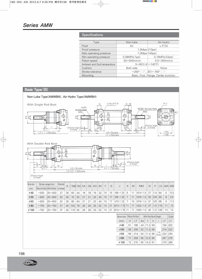
Type Non-lube Air-hydro
Fluid Air L.P.Oil
Proof pressure 1.5Mpa(213psi)
Max.operating pressure 1.0Mpa(140psi}
Min.operating pressure 0.08MPa(1psi) 0.16MPa(22psi)
Piston speed 50~500mm/s 0.5~300mm/s
Ambient and fluid temperature 5~60℃(41~140。F)
Cushion Both side None
Stroke tolerance ~250st : , 251~`750st :
Mounting Basic, Foot, Flange, Center trunnion
+1.4+0
+1.0+0
Specifications
Non-Lube Type(AMWBN), Air-Hydro Type(AMWBH)
With Single Rod Bootwidth
across flats
With Double Rod Boot
фe
фe
WBWA
ØD
Øe
фD
фD
WA
WBфD
фD
фE
A K K A8 ℓ f N N 8f ℓ
h+ℓ
A
G G M2-Rc(PT)P
HK F F K A
CBN N
CB
□SC
□SB
MM
Width Across flats
4-J
LG+Stroke
LG+Stroke
LT+2ℓ+2Stroke
H+
LT+2Stroke
ℓ
Effective lengthof thread
Effective lengthof thread
Effective lengthof threadEffective length
of threadf8
MM
h+ℓLT+ℓ+2Stroke
h+ℓ+Stroke
(Unit:mm)
Bore size (Double)
(mm) H LT фe f h ℓ LT LT
ф40 51 186 43 11.2 59 194 202
ф50 58 206 52 11.2 66 214 222
ф63 58 214 52 11.2 66 222 230
ф80 71 258 65 12.5 80 267 276
ф100 72 270 65 14.0 81 279 288
With Rod Boot(Single) Without Rod Boot
1/4Stroke
Bore size Effective lengthA □SB□SC CA CB фD фE
(mm) Without Rod Boot With Rod Boot of thread
ф40 ~500 20~500 27 30 60 44 18 18 16 32
ф50 ~600 20~600 32 35 70 52 21 21 20 40
ф63 ~600 20~600 32 35 85 64 21 21 20 40
ф80 ~750 20~750 37 40 102 78 26 26 25 52
ф100 ~750 20~750 37 40 116 92 28 28 30 52
F G J K M MM N P LG WA WB
10 15 M8×1.25 6 11 M14×1.5 27 1/4 84 5 10.5
10 17 M8×1.25 7 11 M18×1.5 30 3/8 90 8 9.9
10 17 M10×1.25 7 14 M18×1.5 31 3/8 98 9 11.5
14 21 M12×1.75 11 17 M22×1.5 37 1/2 116 11 13
14 21 M12×1.75 11 17 M26×1.5 40 1/2 126 13 14
Stroke range(mm)
Basic Type/(B)
186-205-AM 2012.9.7 2:36 PM 페이지198 한국원색인쇄사
AQADQ
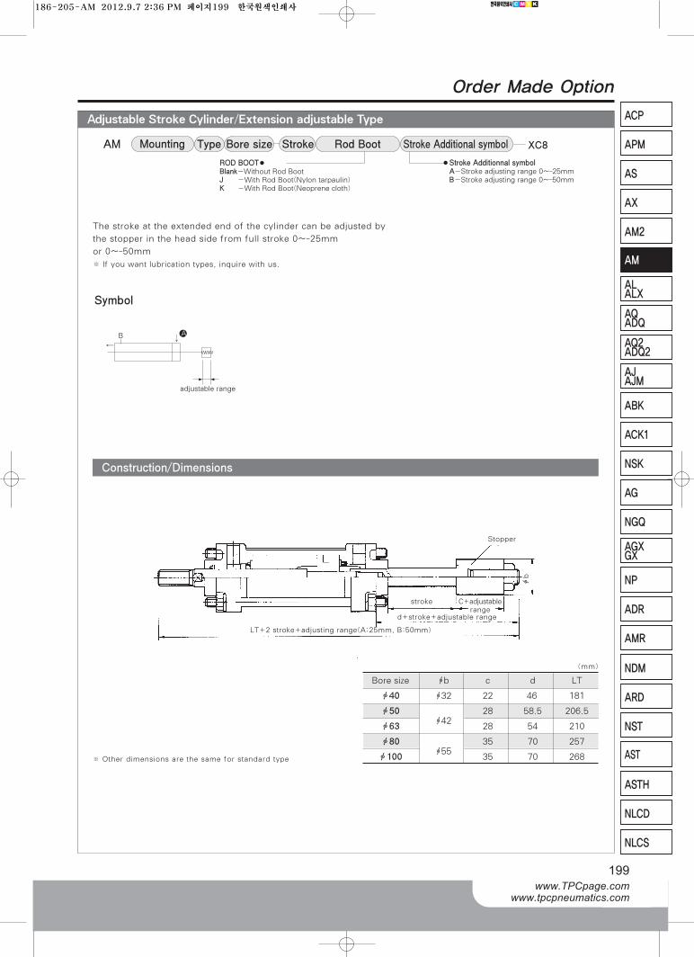
Adjustable Stroke Cylinder/Extension adjustable Type
199www.TPCpage.com
www.tpcpneumatics.com
ACP
APM
AS
AX
AM2
AM
ALALX
AQ2ADQ2
AJAJM
ABK
ACK1
NSK
AG
NGQ
AGXGX
NP
ADR
AMR
NDM
ARD
NST
AST
ASTH
NLCD
NLCS
Order Made Option
Construction/Dimensions
The stroke at the extended end of the cylinder can be adjusted by
the stopper in the head side from full stroke 0~-25mm
or 0~-50mm
※ If you want lubrication types, inquire with us.
Bore sizeAM StrokeType Rod Boot Stroke Additional symbolMounting
●Stroke Additionnal symbolA-Stroke adjusting range 0~-25mmB-Stroke adjusting range 0~-50mm
XC8
Symbol
B
adjustable range
A
Bore size фb c d LT
ф40 ф32 22 46` 181
ф50ф42
28 58.5 206.5
ф63 28 54 210
ф80ф55
35 70 257
ф100 35 70 268
WWW
※ Other dimensions are the same for standard type
LT+2 stroke+adjusting range(A:25mm, B:50mm)
d+stroke+adjustable range
stroke
Stopper
фb
▶ ◀
ROD BOOT●Blank-Without Rod BootJ -With Rod Boot(Nylon tarpaulin)K -With Rod Boot(Neoprene cloth)
C+adjustablerange
(mm)
186-205-AM 2012.9.7 2:36 PM 페이지199 한국원색인쇄사
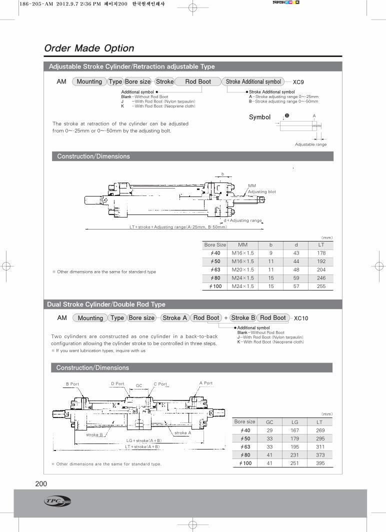
Dual Stroke Cylinder/Double Rod Type
Adjustable Stroke Cylinder/Retraction adjustable Type
200
Order Made Option
Construction/Dimensions
The stroke at retraction of the cylinder can be adjusted
from 0~-25mm or 0~-50mm by the adjusting bolt.
※ Other dimensions are the same for standard type
Bore Size MM b d LT
ф40 M16×1.5 9 43 178
ф50 M16×1.5 11 44 192
ф63 M20×1.5 11 48 204
ф80 M24×1.5 15 59 246
ф100 M24×1.5 15 57 255
b
MM
Adjusting blot
d+Adjusting range
LT+stroke+Adjusting range(A:25mm, B:50mm)
Bore sizeAM StrokeType Rod Boot Stroke Additional symbolMounting
●Stroke Additional symbolA-Stroke adjusting range 0~-25mmB-Stroke adjusting range 0~-50mm
XC9
Additional symbol ●Blank-Without Rod BootJ -With Rod Boot (Nylon tarpaulin)K -With Rod Boot (Neoprene cloth)
Symbol A
Adjustable range
B
WWWW
▶ ◀
Construction/Dimensions
※ Other dimensions are the same for standard type.
stroke B
LG+stroke(A+B)
LT+stroke(A+B)
stroke A
B Port D Port C Port A PortGC
Bore size GC LG LT
ф40 29 167 269
ф50 33 179 295
ф63 33 195 311
ф80 41 231 373
ф100 41 251 395
Two cylinders are constructed as one cylinder in a back-to-back
configuration allowing the cylinder stroke to be controlled in three steps.
※ If you want lubrication types, inquire with us
Bore size Stroke BAM Type Rod BootRod BootStroke AMounting XC10+
●Additional symbolBlank-Without Rod BootJ-With Rod Boot (Nylon tarpaulin)K-With Rod Boot (Neoprene cloth)
(mm)
(mm)
186-205-AM 2012.9.7 2:36 PM 페이지200 한국원색인쇄사
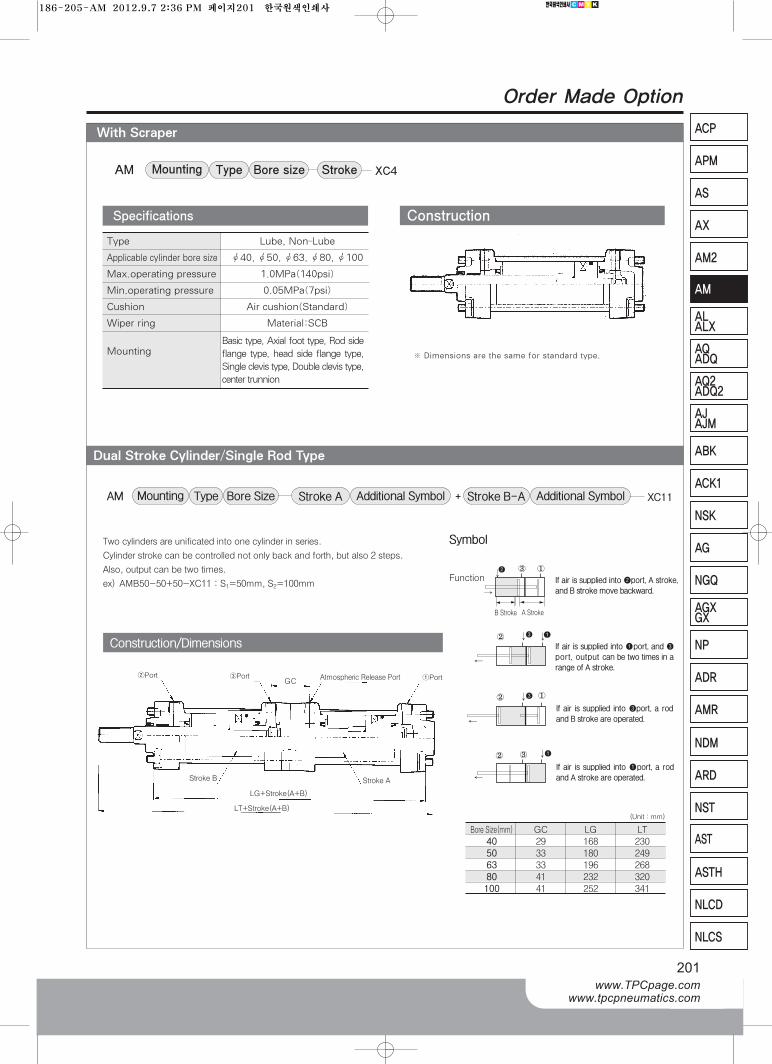
AQADQ
With Scraper
Dual Stroke Cylinder/Single Rod Type
201www.TPCpage.com
www.tpcpneumatics.com
ACP
APM
AS
AX
AM2
AM
ALALX
AQ2ADQ2
AJAJM
ABK
ACK1
NSK
AG
NGQ
AGXGX
NP
ADR
AMR
NDM
ARD
NST
AST
ASTH
NLCD
NLCS
Order Made Option
Bore sizeAM StrokeTypeMounting XC4
Type Lube, Non-Lube
Applicable cylinder bore size Ø40, Ø50, Ø63, Ø80, Ø100
Max.operating pressure 1.0MPa(140psi)
Min.operating pressure 0.05MPa(7psi)
Cushion Air cushion(Standard)
Wiper ring Material:SCB
MountingBasic type, Axial foot type, Rod sideflange type, head side flange type,Single clevis type, Double clevis type,center trunnion
Specifications Construction
※ Dimensions are the same for standard type.
Two cylinders are unificated into one cylinder in series.
Cylinder stroke can be controlled not only back and forth, but also 2 steps.
Also, output can be two times.
ex) AMB50-50+50-XC11 : S1=50mm, S2=100mm
Bore SizeAM Type Additional SymbolStroke A Additional SymbolStroke B-AMounting XC11+
Construction/Dimensions
Bore Size(mm) GC LG LT
40 29 168 230
50 33 180 249
63 33 196 268
80 41 232 320
100 41 252 341
Symbol
If air is supplied into ❷port, A stroke,
and B stroke move backward.
If air is supplied into ❶port, a rod
and A stroke are operated.
If air is supplied into ❸port, a rod
and B stroke are operated.
If air is supplied into ❶port, and ❸
port, output can be two times in a
range of A stroke.
Function①
③
②
② ❸ ①
❶②
❸ ❶
▶ ▶
▶
③
B Stroke A Stroke
❷
▶
(Unit : mm)
②Port
Stroke B
LG+Stroke(A+B)
LT+Stroke(A+B)
Stroke A
③PortGC
Atmospheric Release Port ①Port
186-205-AM 2012.9.7 2:36 PM 페이지201 한국원색인쇄사
202
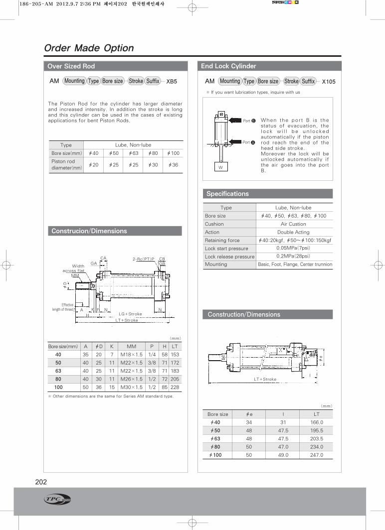
Order Made Option
End Lock CylinderOver Sized Rod
Construction/Dimensions
Specifications
Type Lube, Non-lube
Bore size ф40, ф50, ф63, ф80, ф100
Cushion Air Custion
Action Double Acting
Retaining force ф40:20kgf, ф50~ф100:150kgf
Lock start pressure 0.05MPa(7psi)
Lock release pressure 0.2MPa(28psi)
Mounting Basic, Foot, Flange, Center trunnion
Type
Bore size(mm) ф40 ф50 ф63 ф80 ф100
Piston rod ф20 ф25 ф25 ф30 ф36
diameter(mm)
Lube, Non-lube
Bore size фe l LT
ф40 34 31 166.0
ф50 48 47.5 195.5
ф63 48 47.5 203.5
ф80 50 47.0 234.0
ф100 50 49.0 247.0
Port B
Port A
LT+Strokel
фe
W
Bore sizeAM Stroke SuffixTypeMounting XB5 Bore sizeAM Stroke SuffixTypeMounting X105
The Piston Rod for the cylinder has larger diameterand increased intensity. In addition the stroke is longand this cylinder can be used in the cases of existingapplications for bent Piston Rods. When the port B is the
status of evacuation, thelock will be unlockedautomatically if the pistonrod reach the end of thehead side stroke.Moreover the lock will beunlocked automatically ifthe air goes into the portB.
Construcion/Dimensions
Bore size(mm) A фD K MM P H LT
40 35 20 7 M18×1.5 1/4 58 153
50 40 25 11 M22×1.5 3/8 71 172
63 40 25 11 M22×1.5 3/8 71 183
80 40 30 11 M26×1.5 1/2 72 205
100 50 36 15 M30×1.5 1/2 85 228
※ Other dimensions are the same for Series AM standard type.
Widthacross flat
CA CBGB
2-Rc(PT)PGA
Effectivelength of thread
MM
A K F N N
HLT+Stroke
LG+Stroke
фD
(mm)
(mm)
※ If you want lubrication types, inquire with us
186-205-AM 2012.9.7 2:36 PM 페이지202 한국원색인쇄사
AQADQ
Stainless Steel Rod
With Coil Scraper
203www.TPCpage.com
www.tpcpneumatics.com
ACP
APM
AS
AX
AM2
AM
ALALX
AQ2ADQ2
AJAJM
ABK
ACK1
NSK
AG
NGQ
AGXGX
NP
ADR
AMR
NDM
ARD
NST
AST
ASTH
NLCD
NLCS
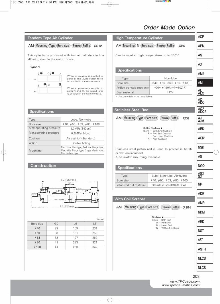
Order Made Option
High Temperature CylinderTandem Type Air Cylinder
Construction
This cylinder is produced with two air cylinders in line
allowing double the output force.
Can be used at high temperature up to 150°C
Stainless steel piston rod is used to protect in harsh
or wet environment.
Auto-switch mounting available
Specifications
Type Lube, Non-lube
Bore size ф40, ф50, ф63, ф80, ф100Max.operating pressure 1.0MPa(140psi)
Min.operating pressure 0.1MPa(14psi)
Cushion Air cushion(Standard)
Action Double Acting
MountingBasic type, Foot type, Rod side flange type,Head side flange type, Single clevis type,Double clevis type
ACB D
C AB DWhen air pressure is supplied toports Ⓑ and Ⓓ,the output forceis doubled in the return stroke.
When air pressure is supplied toports Ⓐ and Ⓒ, the output forceis doubled in the extend stroke.
Bore size GC LG LT
ф40 29 169 231
ф50 33 181 250
ф63 33 197 269
ф80 41 233 321
ф100 41 253 342
※ Auto-switch is not available
Specifications
Type Non-lube
Bore size ф40, ф50, ф63, ф80, ф100
Ambient and media temperature -20~+150℃(-4~302。F)
Seal material FPM
Specifications
Type Lube, Non-lube, Air-hydro
Bore size ф40, ф50, ф63, ф80, ф100
Piston rod nut material Stainless steel(SUS 304)
LG+2Stroke
GC
LT+2Stroke
Symbol
Bore sizeAM Stroke SuffixTypeMounting XC12 Bore sizeAM Stroke SuffixMounting XB6N
Bore sizeAM Stroke SuffixTypeMounting XC6
Bore sizeAM Stroke SuffixTypeMounting X104
Cushion●Blank - Both End
R-Rod EndH-Head EndN-Without cushion
Suffix-Cushion●Blank - Both End Cushion
R-Rod End CushionH-Rod Head CushionN-Non-Cushion
(mm)
186-205-AM 2012.9.7 2:36 PM 페이지203 한국원색인쇄사
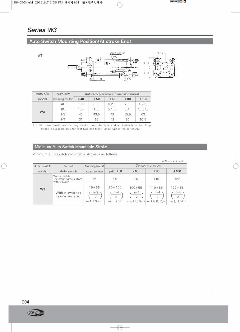
Auto Switch Mounting Position(At stroke End)
Series W3
204
Minimum Auto Switch Mountable Stroke
Auto switch No. of Mounting bracket Center trunnion
model Auto switch except trunnion ф40, ф50 ф63 ф80 ф100
15 90 100 110 120
W3
Minimum auto switch mountable stroke is as follows.
Auto s/w Auto s/w
model mounting position ф40 ф50 ф63 ф80 ф100
AO 0(0) 0(0) 0(2.5) 2(6) 4(7.5)
BO 1(0) 1(0) 5(1.5) 8(4) 10(6.5)
HS 40 43.5 49 55.5 63
HT 31 35 42 50 57.5
W3
Auto s/w placement dimensions(mm)
※ ( ):in parenthesis are for long stroke, non-lube type and air-hydro type, but long
stroke is available only for foot type and front flange type in the series AM
W3With n switches(same surface)
n:No. of auto switch
Auto switch
W3
AO 33 BO
≑HS
≑HT
≑HT
With 2 switch(different, same surface)with 1 switch
15+55
n=1, 2, 3, 4,…
( )100+55
n=4, 8, 12, 16, …
120+55
n=4, 8, 12, 16, …
90+100
n=4, 8, 12, 16, …
110+55
n=4, 8, 12, 16, …
2
n-2
( ) ( ) ( ) ( )2
n-4 n-4
2
n-4
2
n-4
2
186-205-AM 2012.9.7 2:36 PM 페이지204 한국원색인쇄사
AQADQ
205www.TPCpage.com
www.tpcpneumatics.com
ACP
APM
AS
AX
AM2
AM
ALALX
AQ2ADQ2
AJAJM
ABK
ACK1
NSK
AG
NGQ
AGXGX
NP
ADR
AMR
NDM
ARD
NST
AST
ASTH
NLCD
NLCS
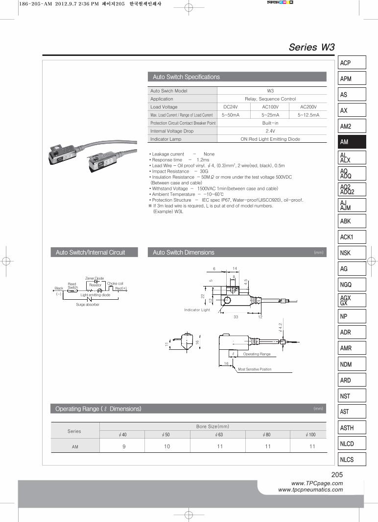
Series W3
•Leakage current - None
•Response time - 1.2ms
•Lead Wire - Oil proof vinyl. Ø4, (0.3)mm2, 2 wire(red, black), 0.5m
•Impact Resistance - 30G
•Insulation Resistance - 50MΩor more under the test voltage 500VDC
(Between case and cable)
•Withstand Voltage - 1500VAC 1min(between case and cable)
•Ambient Temperature - -10~60℃
•Protection Structure - IEC spec IP67, Water-proof(JISCO920), oil-proof.
※ If 3m lead wire is required, L is put at end of model numbers.
(Example) W3L
Auto Swich Model W3
Application Relay, Sequence Control
Load Voltage DC24V AC100V AC200V
Max. Load Current / Range of Load Current 5~50mA 5~25mA 5~12.5mA
Protection Circuit Contact Breaker Point Built-in
Internal Voltage Drop 2.4V
Indicator Lamp ON:Red Light Emitting Diode
Auto Switch Specifications
Auto Switch DimensionsAuto Switch DimensionsAuto Switch/Internal Circuit
6
8
33 12
ℓ
16
4.5
12
5
22
11 16
Ø4.2
14
Indicator Light
Operating Range
Most Sensitive Position
Zener Diode
Choke coil
Red(+)
Light emitting diode
ResistorReedSwitch
Surge absorber
Black
(-)
(mm)
Operating Range (ℓDimensions)
SeriesBore Size(mm)
(mm)
AM 9 10 11 11 11
Ø40 Ø50 Ø63 Ø80 Ø100
186-205-AM 2012.9.7 2:36 PM 페이지205 한국원색인쇄사
Top Related