


Languages
Pages
Legal


Series it2000 Intelligent Pressure Transducer
User’s Manual
Firmware Version 217928G
Stellar Technology Incorporated
Copyright Notice
© 2004 Stellar Technology Incorporated. All rights reserved.
This manual, as well as the software described in it, is furnished under license and may be used or copied only in accordance with the terms of such license. The content of this manual is fur-nished for informational use only, is subject to change without notice, and should not be con-strued as a commitment by Stellar Technology Incorporated. Stellar Technology Incorporated assumes no responsibility or liability for any errors or inaccuracies that may appear in this book.Except as permitted by such license, no part of this publication may be reproduced, stored in a retrieval system, or transmitted in any form or by any means, electronic, mechanical, recording, or otherwise, without the prior written permission of Stellar Technology Incorporated.it2000 is a trademarks of Stellar Technology Incorporated. it2000 logo and the STI logo are trademarks of Stellar Technology Incorporated in the USA. Microsoft, Windows 9x/NT/2000/XP/CE, Microsoft Access, and Microsoft Excel are registered trademarks of Microsoft Corporation. All other products or name brands are the trademarks of their respective holders.
Part number: 217924 Rev G
Contents
Chapter 1: Overview ................................................................................................. 5Standard Features...............................................................................................................................6
Chapter 2: Installation.............................................................................................. 9Mechanical Connection.............................................................................................................................10Electrical Connections ...............................................................................................................................11
Wiring Harness....................................................................................................................................12Analog Output Connections ..............................................................................................................13
Communication Setup...............................................................................................................................14
Chapter 3: Quick-Start Tutorial................................................................................ 15Connection .................................................................................................................................................16Basic Measurements ..................................................................................................................................17
Chapter 4: Using Commands ................................................................................... 19Command and Query Structure ........................................................................................................20Command Entry..................................................................................................................................21Argument Types..................................................................................................................................22Command Usage Rules ......................................................................................................................24Syntax Diagrams .................................................................................................................................24
Chapter 5: Command Reference.............................................................................. 25Measure Subsystem ...................................................................................................................................26Test Commands..........................................................................................................................................28System Commands ....................................................................................................................................30

iv Series it2000 User’s Manual
C H A P T E R 1
Overview
This chapter gives a brief overview of the features and functionality of the Series it2000 Pressure Transducer.
Contents
• Standard Features .........................................................................6
6 Series it2000 User’s Manual
Standard Features
The it2000 is an intelligent pressure transducer that provides both corrected digital and analog outputs.
A host of subsystems enable the it2000 to be compatible with the Standard Commands for Programmable Instruments (SCPI) specification version 1995.0.
Several advanced features are standard on all Series it2000 pressure transducers. Options for custom pressure ports, electrical terminations and media compatibility are available.
Highlights
• Standard Transducer Footprint
• Strain Gage Pressure Sensing
• 0.05% Full Scale Digital Accuracy
• RS-232 Digital Output
• SCPI Command Set
• -40oC to +85oC Operating Temperature Range
• 8-30Vdc Unregulated Input
• All-welded housing
AccuracyA high level of accuracy (0.05% of full scale) is achieved by using the digital compensation algorithms.
FlexibilityTest systems generally utilize either analog or digital subsystems. By incorporating both into the transducer, any system can immediately benefit from STI’s intelligent sensing technology. The choice of various output formats contributes to a high degree of compatibility.
Reliable Sensing TechnologyA high quality low-level signal is essential for any pressure sensing instrument – intelligent or not. The it2000 utilizes the most proven and reliable pressure sensing technology available. Bonded foil strain gage based pressure measurement is very accurate and repeatable in addition to being insensitive to vibration and acceleration. Sensing element design has been optimized to provide the most accurate analog representation of the applied pressure.
STI’s sensing technology allows for the use of various materials for pressure cavity designs. A wide range of media compatibility extends the transducer’s interchangeability with non-intelligent sensors.
Analog OutputExisting test systems that are not yet capable of digital communications can immediately benefit from the advanced capabilities of the it2000. An integrated 12 bit digital to analog converter provides an analog output range of 0.05-4.95 Vdc.
7Chapter 1: Overview
RS-232 OutputAn RS-232 capability provides digital communication to standard PC communication port. Any PC compatible serial communications port can be used.
SCPI CompliantThe it2000 utilizes the limited set of SCPI compliant commands to provide complete control over the data acquisition process.
Complete documentation includes an SCPI tutorial for new users.
TemperatureTemperature variation can be greatly influence the accuracy of pressure measurement. The sensing element, in addition to the microelectronics, is thermally monitored and drift error is removed. Extensive factory calibration testing conforming to MIL-STD-45662A ensures a high degree of instrument characterization.
Data AcquisitionSeveral different types of measurements are required to create a single, high-accuracy pressure measurement. The tension and compression of the pressure sensing element is measured in addition to it’s temperature by a high resolution analog to digital converter.
The analog output is provided by a 12-bit digital to analog converter.
Calibration SoftwareThe Series it2000 Calibration Suite CD contains several programs that run in the Microsoft Windows 9x/NT/2000/XP environments. All of the transducer’s commands can be executed via a click of a button. Additionally, terminal emulation allows for the manual entry of commands. A Chart Recorder program along with a Calibration Profile program are also provided on CD.
An Adobe Acrobat version of this User’s Manual can be found on the CD as well.
Custom ConfigurationAs with all STI products, the it2000 is offered in a standard configuration but can be ordered with a variety of custom options to accommodate most applications. Series it2000 technology can be incorporated into many other models in addition to the standard configuration. Models that measure differential pressure and those featuring external temperature probes are available.
SupportSTI offers complete sales and technical support by contacting our factory directly or through the Internet. Pre-sales information, firmware updates, application notes, and answers to frequently asked questions are available on our website at www.stellartech.com. E-mail addresses are provided for sales and technical support in order to facilitate direct correspondence and expedite problem resolution.

8 Series it2000 User’s Manual
C H A P T E R 2
Installation
This chapter describes the steps to install the Series it2000 Pressure Transducer. Since the it2000 provides an RS-232 interface in addition to analog outputs, the section “Communication Setup” is required for RS-232 interfacing only.
Contents• Mechanical Connection ...............................................................10
• Electrical Connections ..................................................................11
• Communication Setup .................................................................14
10 Series it2000 User’s Manual
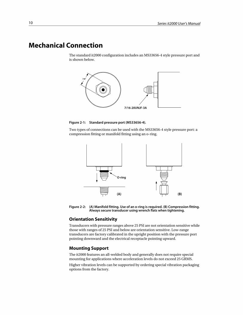
Mechanical ConnectionThe standard it2000 configuration includes an MS33656-4 style pressure port and is shown below.
Figure 2-1: Standard pressure port (MS33656-4).
Two types of connections can be used with the MS33656-4 style pressure port: a compression fitting or manifold fitting using an o-ring.
Figure 2-2: (A) Manifold fitting. Use of an o-ring is required. (B) Compression fitting. Always secure transducer using wrench flats when tightening.
Orientation SensitivityTransducers with pressure ranges above 25 PSI are not orientation sensitive while those with ranges of 25 PSI and below are orientation sensitive. Low-range transducers are factory calibrated in the upright position with the pressure port pointing downward and the electrical receptacle pointing upward.
Mounting SupportThe it2000 features an all-welded body and generally does not require special mounting for applications where acceleration levels do not exceed 25 GRMS.
Higher vibration levels can be supported by ordering special vibration packaging options from the factory.
7/8”
7/16-20UNJF-3A
O-ring
(A) (B)
11Chapter 2: Installation
Electrical ConnectionsThe standard configuration of the it2000 features a welded electrical receptacle and includes a mating connector with wiring harness and DC power supply. Custom configurations are shipped with a User’s Manual Addendum that fully explains the custom options and possible electrical connection differences.
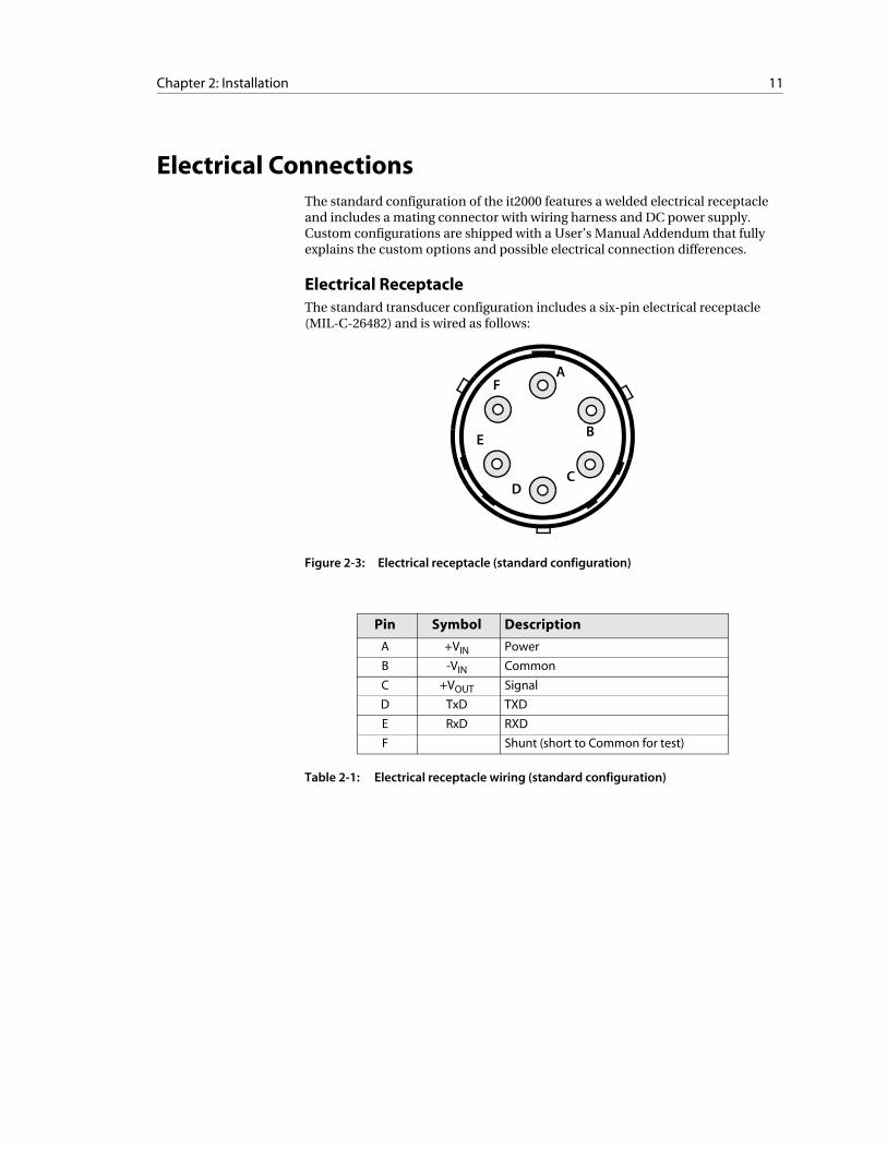
Electrical ReceptacleThe standard transducer configuration includes a six-pin electrical receptacle (MIL-C-26482) and is wired as follows:
Figure 2-3: Electrical receptacle (standard configuration)
Table 2-1: Electrical receptacle wiring (standard configuration)
Pin Symbol Description
A +VIN Power
B -VIN Common
C +VOUT Signal
D TxD TXD
E RxD RXD
F Shunt (short to Common for test)
B
CD
E
FA
12 Series it2000 User’s Manual
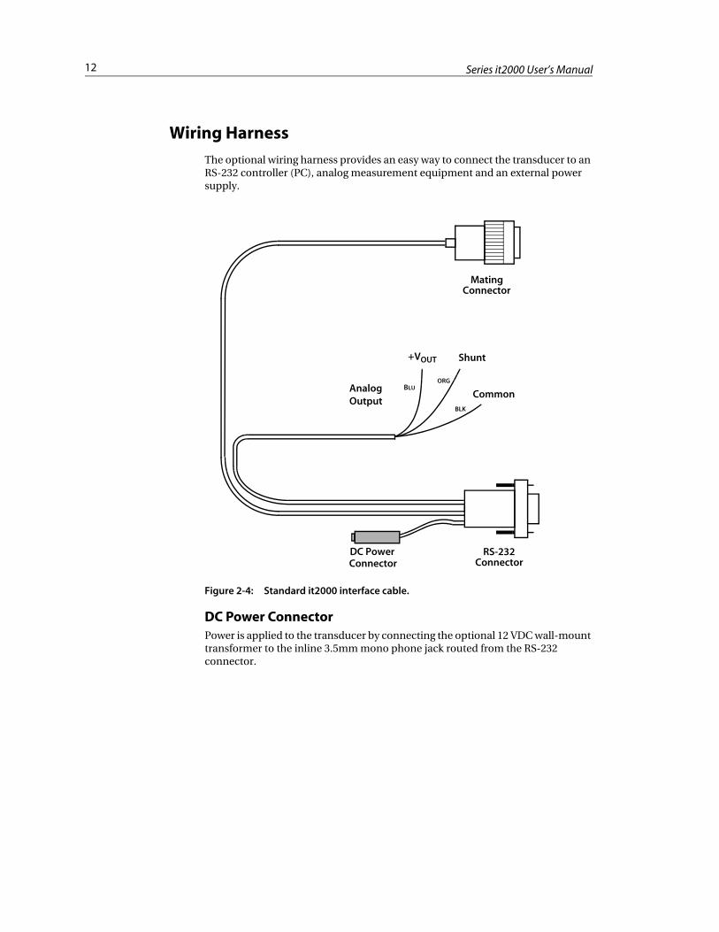
Wiring Harness
The optional wiring harness provides an easy way to connect the transducer to an RS-232 controller (PC), analog measurement equipment and an external power supply.
Figure 2-4: Standard it2000 interface cable.
DC Power ConnectorPower is applied to the transducer by connecting the optional 12 VDC wall-mount transformer to the inline 3.5mm mono phone jack routed from the RS-232 connector.
Mating
DC Power
Analog
+VOUT Shunt
CommonOutput
BLU
BLK
ORG
Connector
RS-232ConnectorConnector
13Chapter 2: Installation
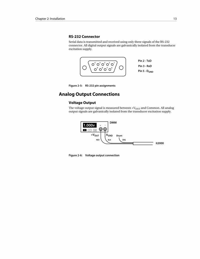
RS-232 ConnectorSerial data is transmitted and received using only three signals of the RS-232 connector. All digital output signals are galvanically isolated from the transducer excitation supply.
Figure 2-5: RS-232 pin assignments
Analog Output Connections
Voltage OutputThe voltage output signal is measured between +VOUT and Common. All analog output signals are galvanically isolated from the transducer excitation supply.
Figure 2-6: Voltage output connection
5 4 3 2 1
9 8 7 6
Pin 2 - TxD
Pin 3 - RxD
Pin 5 - DGND
1.000vV I R
+ _
Shunt
ORGBLKRED
+VOUT AGND
it2000
DMM
14 Series it2000 User’s Manual
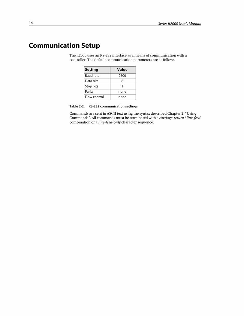
Communication SetupThe it2000 uses an RS-232 interface as a means of communication with a controller. The default communication parameters are as follows:
Table 2-2: RS-232 communication settings
Commands are sent in ASCII text using the syntax described Chapter 2, “Using Commands”. All commands must be terminated with a carriage-return / line-feed combination or a line-feed-only character sequence.
Setting Value
Baud rate 9600
Data bits 8
Stop bits 1
Parity none
Flow control none
C H A P T E R 3
Quick-Start Tutorial
This chapter gives you a quick guide on how to connect Series it2000 Pressure Transducer and start using it’s basic functionality.
Contents• Connection ....................................................................................16
• Basic Measurements .....................................................................17
16 Series it2000 User’s Manual
Connection
The standard Series it2000 Pressure Transducer has two output modes:
• Digital pressure and temperature (requires a RS-232 connection to a PC and a Terminal program).
• Analog pressure output, V (requires connection to a voltmeter).
For more details on each type of connection see Chapter 4, “Installation”. The standard Series it2000 Pressure Transducer may provide digital and analog outputs at the same time.
17Chapter 3: Quick-Start Tutorial
Basic Measurements
To make basic digital pressure or temperature measurements you may use the standard Windows Terminal program with appropriate settings.
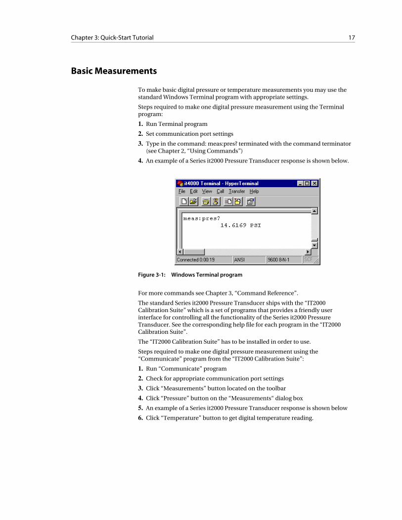
Steps required to make one digital pressure measurement using the Terminal program:
1. Run Terminal program
2. Set communication port settings
3. Type in the command: meas:pres? terminated with the command terminator (see Chapter 2, “Using Commands”)
4. An example of a Series it2000 Pressure Transducer response is shown below.
Figure 3-1: Windows Terminal program
For more commands see Chapter 3, “Command Reference”.
The standard Series it2000 Pressure Transducer ships with the “IT2000 Calibration Suite” which is a set of programs that provides a friendly user interface for controlling all the functionality of the Series it2000 Pressure Transducer. See the corresponding help file for each program in the “IT2000 Calibration Suite”.
The “IT2000 Calibration Suite” has to be installed in order to use.
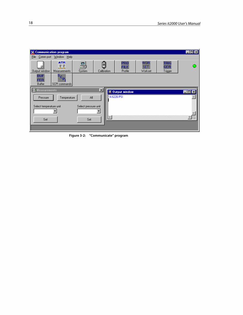
Steps required to make one digital pressure measurement using the “Communicate” program from the “IT2000 Calibration Suite”:
1. Run “Communicate” program
2. Check for appropriate communication port settings
3. Click “Measurements” button located on the toolbar
4. Click “Pressure” button on the “Measurements“ dialog box
5. An example of a Series it2000 Pressure Transducer response is shown below
6. Click “Temperature” button to get digital temperature reading.
18 Series it2000 User’s Manual
Figure 3-2: “Communicate“ program
C H A P T E R 4
Using Commands
The it2000 is controlled through the RS-232 interface using a large group of commands and queries. This chapter describes the syntax these commands and queries use and the conventions the transducer uses to process them. The commands and queries themselves are listed in Chapter 3, “Command Reference”.
Contents• Command and Query Structure ...................................................20
• Command Entry ............................................................................21
• Argument Types ............................................................................22
• Command Usage Rules .................................................................24
• Syntax Diagrams ............................................................................24
20 Series it2000 User’s Manual
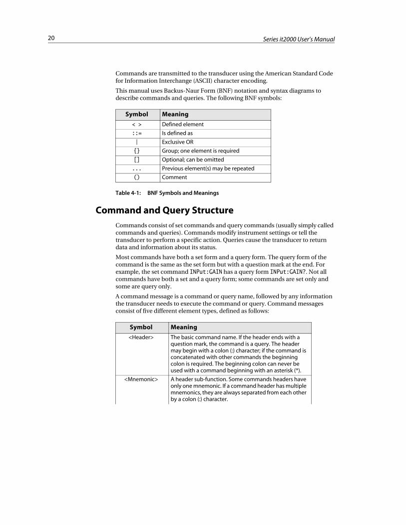
Commands are transmitted to the transducer using the American Standard Code for Information Interchange (ASCII) character encoding.
This manual uses Backus-Naur Form (BNF) notation and syntax diagrams to describe commands and queries. The following BNF symbols:
Table 4-1: BNF Symbols and Meanings
Command and Query Structure
Commands consist of set commands and query commands (usually simply called commands and queries). Commands modify instrument settings or tell the transducer to perform a specific action. Queries cause the transducer to return data and information about its status.
Most commands have both a set form and a query form. The query form of the command is the same as the set form but with a question mark at the end. For example, the set command INPut:GAIN has a query form INPut:GAIN?. Not all commands have both a set and a query form; some commands are set only and some are query only.
A command message is a command or query name, followed by any information the transducer needs to execute the command or query. Command messages consist of five different element types, defined as follows:
Symbol Meaning
< > Defined element
::= Is defined as
| Exclusive OR
{} Group; one element is required
[] Optional; can be omitted
... Previous element(s) may be repeated
() Comment
Symbol Meaning
<Header> The basic command name. If the header ends with a question mark, the command is a query. The header may begin with a colon (:) character; if the command is concatenated with other commands the beginning colon is required. The beginning colon can never be used with a command beginning with an asterisk (*).
<Mnemonic> A header sub-function. Some commands headers have only one mnemonic. If a command header has multiple mnemonics, they are always separated from each other by a colon (:) character.
21Chapter 4: Using Commands
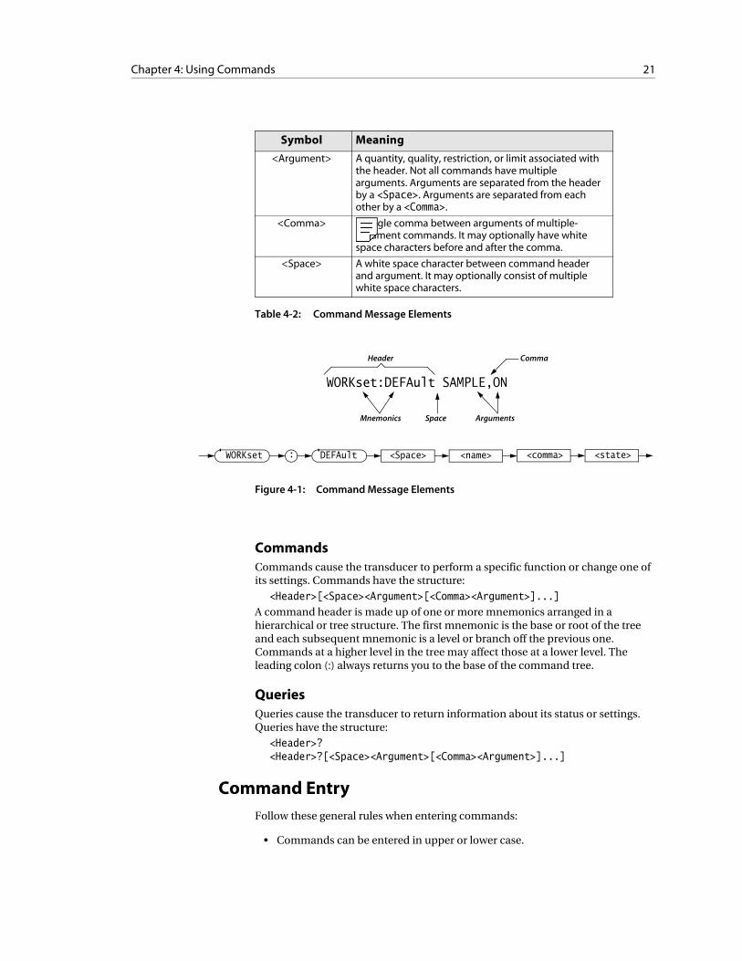
Table 4-2: Command Message Elements
Figure 4-1: Command Message Elements
CommandsCommands cause the transducer to perform a specific function or change one of its settings. Commands have the structure:
<Header>[<Space><Argument>[<Comma><Argument>]...]
A command header is made up of one or more mnemonics arranged in a hierarchical or tree structure. The first mnemonic is the base or root of the tree and each subsequent mnemonic is a level or branch off the previous one. Commands at a higher level in the tree may affect those at a lower level. The leading colon (:) always returns you to the base of the command tree.
QueriesQueries cause the transducer to return information about its status or settings. Queries have the structure:
<Header>?<Header>?[<Space><Argument>[<Comma><Argument>]...]
Command Entry
Follow these general rules when entering commands:
• Commands can be entered in upper or lower case.
<Argument> A quantity, quality, restriction, or limit associated with the header. Not all commands have multiple arguments. Arguments are separated from the header by a <Space>. Arguments are separated from each other by a <Comma>.
<Comma> A single comma between arguments of multiple-argument commands. It may optionally have white space characters before and after the comma.
<Space> A white space character between command header and argument. It may optionally consist of multiple white space characters.
Symbol Meaning
WORKset:DEFAult SAMPLE,ON
Mnemonics Space Arguments
CommaHeader
WORKset : DEFAult <Space> <name> <state><comma>
22 Series it2000 User’s Manual
• Any command can be preceded with white space characters. White space characters include any combination of the ASCII control characters 00 through 09 and 0B through 20 hexadecimal (0 through 9 and 11 through 32 decimal).
• The transducer ignores commands consisting of any combination of white space characters and line feeds.
SuffixesSome mnemonics have a plural form. The mnemonic that is expressed in plural form indicates that it represents more than one instance of a subsystem. This is illustrated as follows:
TEST:INP5?
All suffixes have a default value of one and is used when the suffix is not specified. Suffixes are enclosed in brackets in the command syntax descriptions to indicate their optional inclusion. The brackets are not to be included in actual usage.
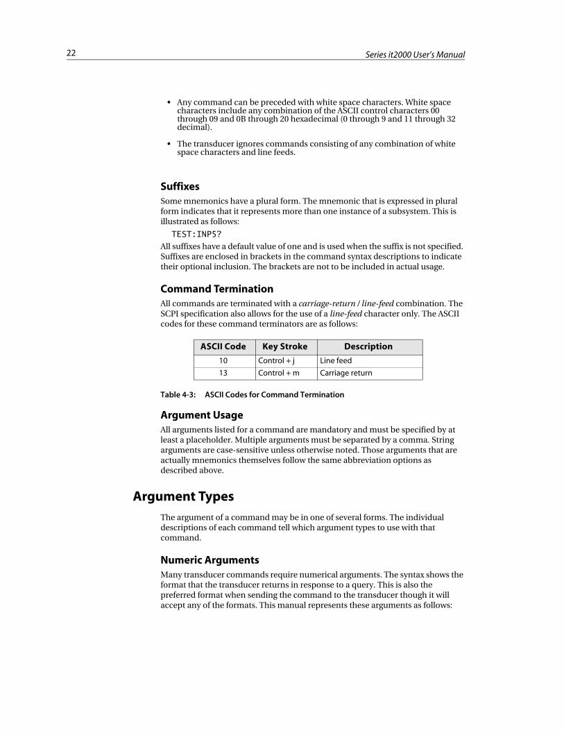
Command TerminationAll commands are terminated with a carriage-return / line-feed combination. The SCPI specification also allows for the use of a line-feed character only. The ASCII codes for these command terminators are as follows:
Table 4-3: ASCII Codes for Command Termination
Argument UsageAll arguments listed for a command are mandatory and must be specified by at least a placeholder. Multiple arguments must be separated by a comma. String arguments are case-sensitive unless otherwise noted. Those arguments that are actually mnemonics themselves follow the same abbreviation options as described above.
Argument Types
The argument of a command may be in one of several forms. The individual descriptions of each command tell which argument types to use with that command.
Numeric ArgumentsMany transducer commands require numerical arguments. The syntax shows the format that the transducer returns in response to a query. This is also the preferred format when sending the command to the transducer though it will accept any of the formats. This manual represents these arguments as follows:
ASCII Code Key Stroke Description
10 Control + j Line feed
13 Control + m Carriage return
23Chapter 4: Using Commands
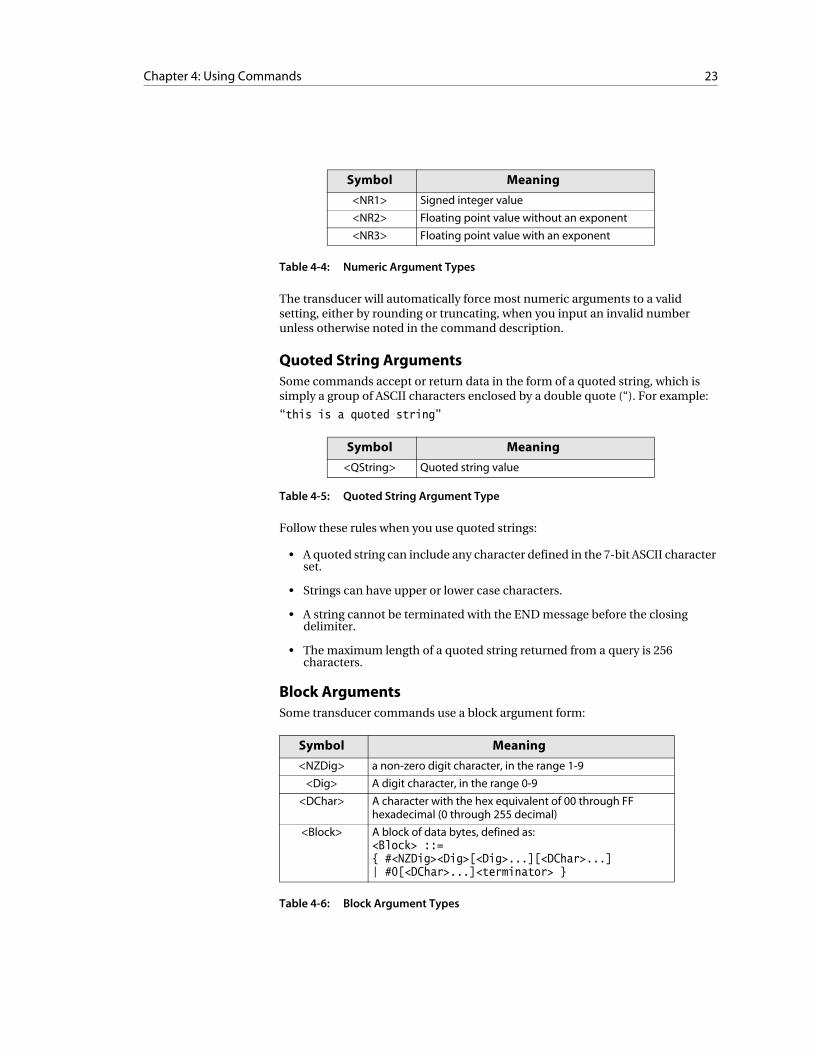
Table 4-4: Numeric Argument Types
The transducer will automatically force most numeric arguments to a valid setting, either by rounding or truncating, when you input an invalid number unless otherwise noted in the command description.
Quoted String ArgumentsSome commands accept or return data in the form of a quoted string, which is simply a group of ASCII characters enclosed by a double quote (“). For example:
“this is a quoted string”
Table 4-5: Quoted String Argument Type
Follow these rules when you use quoted strings:
• A quoted string can include any character defined in the 7-bit ASCII character set.
• Strings can have upper or lower case characters.
• A string cannot be terminated with the END message before the closing delimiter.
• The maximum length of a quoted string returned from a query is 256 characters.
Block ArgumentsSome transducer commands use a block argument form:
Table 4-6: Block Argument Types
Symbol Meaning
<NR1> Signed integer value
<NR2> Floating point value without an exponent
<NR3> Floating point value with an exponent
Symbol Meaning
<QString> Quoted string value
Symbol Meaning
<NZDig> a non-zero digit character, in the range 1-9
<Dig> A digit character, in the range 0-9
<DChar> A character with the hex equivalent of 00 through FF hexadecimal (0 through 255 decimal)
<Block> A block of data bytes, defined as:<Block> ::={ #<NZDig><Dig>[<Dig>...][<DChar>...]| #0[<DChar>...]<terminator> }
24 Series it2000 User’s Manual
<NZDig> specifies the number of <Dig> elements that follow. Taken together, the <Dig> elements form a decimal integer that specifies how many <DChar> elements follow.
Command Usage Rules
It is important to keep the following rules in mind when using the commands in this reference guide:
1. Commands are case-insensitive.
2. All commands are terminated by a carriage-return / line-feed combination or a linefeed.
3. All arguments are required.
4. Multiple arguments must be separated by a comma.
5. String arguments are case-sensitive unless they are a mnemonic.
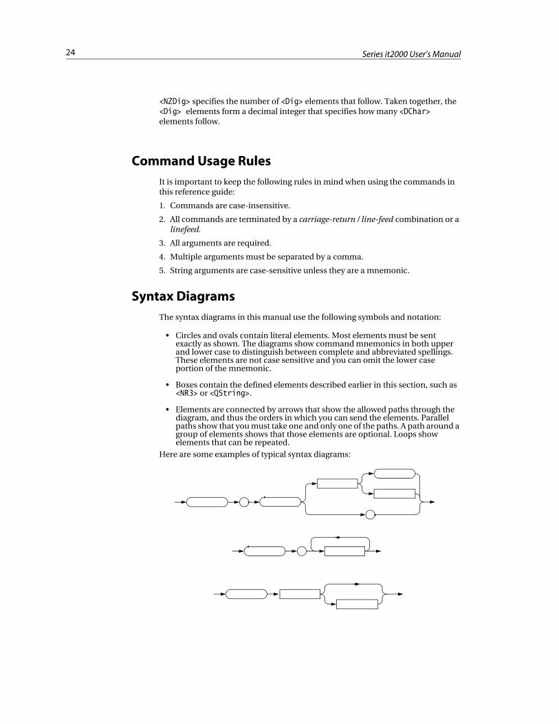
Syntax Diagrams
The syntax diagrams in this manual use the following symbols and notation:
• Circles and ovals contain literal elements. Most elements must be sent exactly as shown. The diagrams show command mnemonics in both upper and lower case to distinguish between complete and abbreviated spellings. These elements are not case sensitive and you can omit the lower case portion of the mnemonic.
• Boxes contain the defined elements described earlier in this section, such as <NR3> or <QString>.
• Elements are connected by arrows that show the allowed paths through the diagram, and thus the orders in which you can send the elements. Parallel paths show that you must take one and only one of the paths. A path around a group of elements shows that those elements are optional. Loops show elements that can be repeated.
Here are some examples of typical syntax diagrams:
C H A P T E R 5
Command Reference
This chapter describes each of the commands used to configure and control the it2000 pressure transducer. The command reference is broken down into several groups of related functionality.
Contents
• Measure Subsystem ......................................................................26
• Test Commands ............................................................................28
• System Commands .......................................................................30
26 Series it2000 User’s Manual
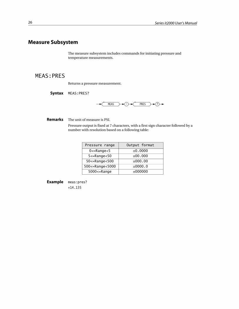
Measure Subsystem
The measure subsystem includes commands for initiating pressure and temperature measurements.
MEAS:PRESReturns a pressure measurement.
Syntax MEAS:PRES?
Remarks The unit of measure is PSI.
Pressure output is fixed at 7 characters, with a first sign character followed by a number with resolution based on a following table:
Example meas:pres?
+14.135
MEAS : PRES ?
Pressure range Output format
0<=Range<5 ±0.0000
5<=Range<50 ±00.000
50<=Range<500 ±000.00
500<=Range<5000 ±0000.0
5000<=Range ±000000
27Chapter 5: Command Reference
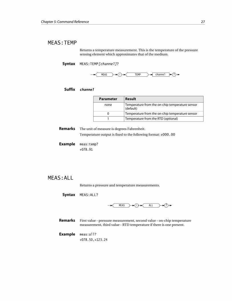
MEAS:TEMPReturns a temperature measurement. This is the temperature of the pressure sensing element which approximates that of the medium.
Syntax MEAS:TEMP[channel]?
Suffix channel
Remarks The unit of measure is degrees Fahrenheit.
Temperature output is fixed to the following format: ±000.00
Example meas:temp?
+078.91
MEAS:ALLReturns a pressure and temperature measurements.
Syntax MEAS:ALL?
Remarks First value - pressure measurement, second value - on-chip temperature measurement, third value - RTD temperature if there is one present.
Example meas:all?
+078.50,+123.24
MEAS : TEMP channel ?
Parameter Result
none Temperature from the on-chip temperature sensor (default)
0 Temperature from the on-chip temperature sensor
1 Temperature from the RTD (optional)
MEAS : ALL ?
28 Series it2000 User’s Manual
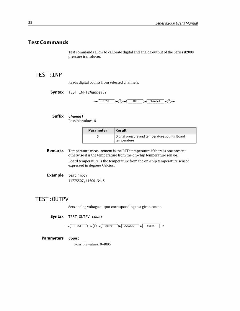
Test Commands
Test commands allow to calibrate digital and analog output of the Series it2000 pressure transducer.
TEST:INPReads digital counts from selected channels.
Syntax TEST:INP[channel]?
Suffix channelPossible values: 5
Remarks Temperature measurement is the RTD temperature if there is one present, otherwise it is the temperature from the on-chip temperature sensor.
Board temperature is the temperature from the on-chip temperature sensor expressed in degrees Celcius.
Example test:inp5?
11775507,41600,34.5
TEST:OUTPVSets analog voltage output corresponding to a given count.
Syntax TEST:OUTPV count
Parameters count
Possible values: 0-4095
INPTEST : channel ?
Parameter Result
5 Digital pressure and temperature counts, Board temperature
TEST : OUTPV <Space> count
29Chapter 5: Command Reference
The count is a value which will be send to the digital-to-analog converter to set the analog output.
Remarks This command is used to calibrate a transducer’s analog output during the factory calibration process.
Example test:outpv 2768
30 Series it2000 User’s Manual
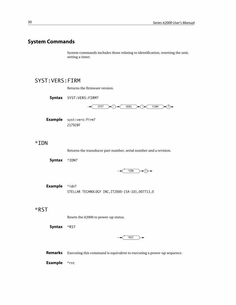
System Commands
System commands includes those relating to identification, resetting the unit, setting a timer.
SYST:VERS:FIRMReturns the firmware version.
Syntax SYST:VERS:FIRM?
Example syst:vers:firm?
217928F
*IDNReturns the transducer part number, serial number and a revision.
Syntax *IDN?
Example *idn?
STELLAR TECHNOLOGY INC,IT2000-15A-101,007713,0
*RSTResets the it2000 to power-up status.
Syntax *RST
Remarks Executing this command is equivalent to executing a power-up sequence.
Example *rst
VERS FIRM:SYST : ?
*IDN ?
*RST
31Chapter 5: Command Reference
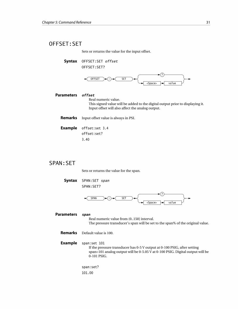
OFFSET:SETSets or returns the value for the input offset.
Syntax OFFSET:SET offset
OFFSET:SET?
Parameters offsetReal numeric value.This signed value will be added to the digital output prior to displaying it. Input offset will also affect the analog output.
Remarks Input offset value is always in PSI.
Example offset:set 3.4
offset:set?
3.40
SPAN:SETSets or returns the value for the span.
Syntax SPAN:SET span
SPAN:SET?
Parameters spanReal numeric value from (0..150] interval.The pressure transducer’s span will be set to the span% of the original value.
Remarks Default value is 100.
Example span:set 101If the pressure transducer has 0-5 V output at 0-100 PSIG, after setting span=101 analog output will be 0-5.05 V at 0-100 PSIG. Digital output will be 0-101 PSIG.
span:set?
101.00
OFFSET SET
value<Space>
:
?
SPAN SET
value<Space>
:
?
32 Series it2000 User’s Manual
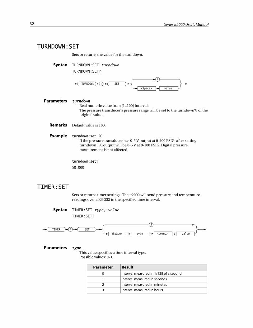
TURNDOWN:SETSets or returns the value for the turndown.
Syntax TURNDOWN:SET turndown
TURNDOWN:SET?
Parameters turndownReal numeric value from [1..100] interval.The pressure transducer’s pressure range will be set to the turndown% of the original value.
Remarks Default value is 100.
Example turndown:set 50If the pressure transducer has 0-5 V output at 0-200 PSIG, after setting turndown=50 output will be 0-5 V at 0-100 PSIG. Digital pressure measurement is not affected.
turndown:set?
50.000
TIMER:SETSets or returns timer settings. The it2000 will send pressure and temperature readings over a RS-232 in the specified time interval.
Syntax TIMER:SET type, value
TIMER:SET?
Parameters typeThis value specifies a time interval type.Possible values: 0-3.
TURNDOWN SET
value<Space>
:
?
TIMER SET:
<Space> type
?
value<comma>
Parameter Result
0 Interval measured in 1/128 of a second
1 Interval measured in seconds
2 Interval measured in minutes
3 Interval measured in hours
33Chapter 5: Command Reference
valueNumeric value from 0 to 255.This value determines a time interval in specified units of measure.
Remarks Value set to 0 will stop the timer function.
In 1/128 mode not every setting will result in a proper response rate due to the IT2000 performance limitations.
Example timer:set 1, 100
timer:set?
sec,100

34 Series it2000 User’s Manual
Index
Symbols* (asterisk) 20: (colon) 20, 21
Aanalog output 6, 7, 13, 16, 28, 29,31Analog Output Connections 13
Voltage Output 13argument 21, 22, 23Argument Types 22
Block Arguments 23Numeric Arguments 22Quoted String Arguments 23
ASCII (American Standard Code forInformation Interchange) 14, 20,22, 23
BBackus-Naur Form (BNF) 20Basic Measurements 17
Ccarriage-return 14, 22, 24case
lower 21, 23, 24upper 21, 23, 24
channel 28Command Entry 21
Argument Usage 22Command Termination 22Suffixes 22
Command Reference 25Input Subsystem
INPutOFFSet
VALUE 31Measure Subsystem 26
MEASureALL 27PRESsure 26TEMPerature 27
UNITPRESsure 27
System Commands 30*IDN 30*RST 30SYSTem
VERSionFIRMware 30
Test Commands 28TEST
INPut 28OUTPV 28
Trigger SubsystemTRIGger
PRESsure 32Command Usage Rules 24Commands and Query Structure 20
Commands 21Queries 21
communication port 7, 17Communication Setup 14current loop 11
Ddata acquisition 7Description
Data Acquisition 7digital
communications 6count 28output 6, 16, 28, 31pressure 16, 17temperature 16, 17
digital to analog converter 6, 7, 29
EElectrical Connections 11
Electrical Receptical 11
Ffirmware 30foil strain gage 6
Ggain 20
Lline-feed 14, 22, 24
MMechanical Connection 10
Mounting Support 10Orientation Sensitivity 10
message 20, 23mnemonic 20, 21, 22, 24
Ooffset
input 31output
voltage 28
Pprofile 7
RRS-232 6, 7, 13, 14, 16, 19
SStandard Commands for Program-mable Instruments (SCPI) 6, 22Standard Features
Accuracy 6Analog Output 6Calibration Software 7Custom Configuration 7Flexibility 6Reliable Sensing Technology 6RS-232 Output 7SCPI Compliant 7Support 7Temperature 7
suffix 28Syntax Diagrams 24
Wwhite space 21, 22Wiring Harness 12
DC Power Connector 12RS-232 Connector 13

36 Series it2000 User’s Guide
Top Related