


Languages
Pages
Legal


Page 1 of 4
SEMINOLE TRIBE OF FLORIDA
Denise DeCarolis Carpenter Purchasing Department
Director
6300 STIRLING ROAD HOLLYWOOD, FLORIDA 33024
PHONE (954) 966-6300 x11170 FAX (954) 967-3478
E-MAIL: [email protected]
WEBSITE: http://www.seminoletribe.com
Tribal Officers:
MARCELLUS W. OSCEOLA, JR.
Chairman
MITCHELL CYPRESS Vice-Chairman
LAVONNE ROSE
Secretary
PETER HAHN Treasurer
REQUEST FOR PROPOSALS
FOR LAKELAND BATHROOM STRUCTURE FACILITIES RENOVATION
RFP 14-2018
Addendum No. 2, issued March 5, 2018
This Addendum No. 2 is hereby made a part of RFP 14-2018 and has been issued to provide a revised Schedule of Values as well as to provide answers to questions as well as additional information:
The following questions/inquiries are being addressed through this addendum:
1. Is the referenced soil report available? Yes, is available, geotechnical studies are attached.
2. Who will be responsible for layout of structure, surveying, as-builds and other surveyor related requirements? Surveying is by STOF and As-builds by GC.
3. Is a permit required and who pays for permit fees? Permits are paid for by STOF.
4. General Conditions note 23 requires GC to provide job site sign. Please confirm. Not Required
5. General Conditions note 24 requires 6 inspections at a cost of $550.00 each please confirm the GC pays for these inspections. Not required.

Lakeland Bathroom Structure Facilities Renovation Addendum 2, RFP 14-2018
Seminole Tribe of Florida CONFIDENTIAL Page 2 of 4
6. Please provide specifications and confirm thickness of gravel for the retention area. Page C2 section B-B. See rev. sheet C-2, Thickness of gravel is 3” thick.
7. Sheet C2 “proposed drain field & reserve area” seems to be by General Contractor. Sheet C# calls for the proposed drain field (at same area) to be by STOF Public Works Department. Please clarify scope and responsibility. For the drain field and reserve area? Proposed drain field, pump and the 540 HDPE pump tank are by STOF. GC is to stub out plumbing, 5’ from Building.
8. Please provide the work limits for silt fence installation. See attached
9. Will a temporary fence or additional security be required at project site? If so what are the fence limits and layout. No temporary fence required.
10. What will be the extent of site restoration and or sod replacement? Item 31.500 provide 3,000 sf of Sod an allowance.
11. Is there irrigation at the site? If so what are the removal and or re-location requirements. No irrigation required.
12. Sheet A-1 Floor plan shows a removable grate at entry to each restroom. No other details provided. Please provide section, specifications and tie-in to plumbing and drainage if required. Removable great has been removed.
13. The interior 4” masonry partitions are free standing extending to 7’-0” AFF without support. Please confirm this is accurate. There is a conc. Tie-beam 4”x8” w/ 1#4 cont.
14. As per section 1-A/3 the 4” cmu will have shower heads and internal plumbing installed. Please confirm the selected valves and rough in will fit within 4” unsupported cmu partitions. Seal opening watertight w/NP-1 or similar
15. Sheet A-2 rear and front elevation calls for C.J. at stucco walls. Please provide a C.J. detail. See Attached.
16. Room finish schedule sheet A-4 calls for walls to receive W-1 finish which is stucco. Wall section(s) in sheet A-3 shows wet shower areas to be
Lakeland Bathroom Structure Facilities Renovation Addendum 2, RFP 14-2018
Seminole Tribe of Florida CONFIDENTIAL Page 3 of 4
tiled. Please width of tile area, tile specifications and substrate requirements to receive the wall tile. See Attached.
17. Please provide specification for “colored concrete” as specified for concrete floor. Provide integrally colored concrete “Gray”.
18. Please provide attic access requirements. As per FBC R807.
19. Note Sheet A-3 requires contractor to follow NOA including installation of Fire Shield. Please provide requirements and specifications for Fire Shield. Remove “Fire shield”
20. Sheet A-1 material finish legend are calling for colored concrete floors w/broom finish. What color are the floors to be? The finish should be smooth and the color is going to be Medium gray (Integrally cast-in-place)
21. Sheet A-1 is showing a removable grate at each restroom entrance. What are the intentions of this grate? Please provide the necessary information to price (make, model, finish) Please remove Removable grate has been removed from plans
22. Sheet P-2 is showing all water supplies to be over head. Will the tie-beam that is being placed on top of the masonry walls interfere with this? NO, Please provide a detail for the plumbing penetrations through the tie-beam to allow for plumbing to be ran into the CMU walls. Seal opening watertight with NP-1 or similar.
23. Sheet A-3 is showing plumbing fixtures for the showers to be in the 4” thick masonry walls this may propose a challenge due the limited room in the cavity of a 4” CMU. The 4” masonry walls are partial height and do not come up to the ceiling. The isometric is showing the plumbing coming from overhead. Please advise if this is correct? This will leave a 1’ section of exposed pluming pipes above the 4” masonry walls. Pipes should be running thru 4” masonry walls, the Plumbing isometric in sheet P-2 and Water Supply plan on sheet P-1 will be corrected.
24. The water piping entry detail on sheet P-2 as well as the water supply plan on sheet P-1 is showing surface mounted water supply drops to be surface mounted. Please verify We will remove water piping entry detail. Piping is not surface mounted.
25. The roof overhang detailed on 2-S2 is showing the top chord of the truss overhanging the concrete beam, however, details 1, 2, & 3 are showing a different overhang detail that includes a soffit. Which detail is correct?

Lakeland Bathroom Structure Facilities Renovation Addendum 2, RFP 14-2018
Seminole Tribe of Florida CONFIDENTIAL Page 4 of 4
Follow overhang type showed on sheet A-3 details 1, 2, 3. The ties and straps shall remain as per structural drawings.
26. Sheet C2 Section B-B is calling for 3’ of gravel. Please verify the depth of 3’ is correct. Thickness of gravel is 3 inches.
27. Exhibit A Schedule of values– Division 31 Earthwork is calling for removal of trees, this is not shown on the civil drawings. Please provide a drawing indicating the trees to be removed. See attached graphics.
28. Exhibit A Schedule of values – Note 2 Drawing List does not match the drawings provided. Please advise. Coordinate with STOF.
29. Is the plumbing supply to be tied into the existing water pump shown on the civil sheets? If not please indicate where the water supply is coming from and this will be tied-in. Plumbing supply to be tied to the existing water pump.
30. During our site visit it was said that all plumbing fixtures to be American Standard, however, the drawings are calling for Kohler. Please provide a list of American Standard fixtures if this is correct? Coordinate with STOF.
31. During our site visit there was mention of an alternate shingle roof. This is not shown on the plan set. Please advise? A new schedule of values may be required to allow us to input alternates, if required. Coordinate with STOF.
32. Addendum #1 is showing the drain field to be handled by STOF Public Works Department. Is the contractor to the excavation and fill of the drain field per note on C3 as well as handle the pump, tank and connections? Please provide the Gould’s pump model # required. Proposed drain field, pump and the 540 HDPE pump tank is by STOF. GC is to stub out plumbing, 5’ from Building.
33. Will a revised Schedule of Values be provided to accommodate changes? Coordinate with STOF.
34. Sheet A-0 General Requirement note 23 states to provide a project sign. Please provided the requirements for this sign. Not required.
35. Sheet E-1 indicated and overhead connection on the electrical riser. Please confirm that the utility company will connect to the riser? If the utility company is not responsible for this connection, please indicate where the feed connection is located. Coordinate with STOF.
ATTACHMENTS INCLUDE:
(1) Revised Schedule of Values (2) Geotechnical Report & (3) Graphics


Geotechnical Engineering Report
Proposed Restroom Facility / Septic System Bryant Road Seminole Reservation – Site A Lakeland, Florida
Prepared for:
G. Batista & Associates
Prepared by:
MADRID ENGINEERING GROUP, INC.
2030 State Road 60 East Bartow, FL 33830
863-533-9007
Project No. 13269 October 2017
Madrid Engineering Group, Inc.

TABLE OF CONTENTS
1.0 INTRODUCTION AND PROJECT DESCRIPTION ................................................. 1
1.1 General ......................................................................................................... 1
1.2 Site Location and Description ....................................................................... 1
1.3 Soil Survey ................................................................................................... 1
2.0 FIELD EXPLORATION............................................................................................ 2
3.0 SUBSURFACE CONDITIONS AND LABORATORY TESTING .............................. 3
3.1 Subsurface Soil Conditions .......................................................................... 3
3.2 Groundwater Conditions and Seasonal High Ground Water ........................ 3
3.3 Laboratory Testing ........................................................................................ 4
4.0 EVALUATION AND RECOMMENDATIONS FOR DESIGN .................................... 5
4.1 General Considerations ................................................................................ 5
4.2 Restroom Facility Shallow Foundation Analysis and Evaluation .................. 5
4.3 Site Preparation ............................................................................................ 6
4.3.1 Clearing and Stripping ......................................................................... 6
4.3.2 Proof-Rolling ....................................................................................... 6
4.3.3 Earthwork and Compaction ................................................................. 6
5.0 QUALITY ASSURANCE .......................................................................................... 7
6.0 LIMITATIONS .......................................................................................................... 7
FIGURES
Figure 1 Site Location Map
Figure 2 NRCS/USDA Soils Map
Figure 3 Testing Location Map (Client Provided)
APPENDICES
Appendix A Soil Boring Log
Appendix B Laboratory Testing Reports

1.0 INTRODUCTION AND PROJECT DESCRIPTION
1.1 General
Madrid Engineering Group (Madrid) is pleased to submit this report summarizing
the results from our subsurface soil exploration and geotechnical engineering evaluation
for the proposed CMU restroom facility at the Bryant Road Seminole Tribe of Florida
Reservation in Lakeland, Florida. Our conclusions and recommendations are based on
the results of our field exploration, laboratory tests, and appropriate engineering
analyses.
Based on information provided by the client (G. Batista & Associates), the project
includes the construction of a new CMU restroom facility (approximate 600 to 700
square feet based upon client defined limits) and associated septic system on a partially
developed portion of the reservation land. No loading conditions were provided but
loads are anticipated to be modest and typical for this type of structure.
The purpose of this investigation was to provide an evaluation of the existing
subsurface conditions at the boring location and to identify constraints or limitations (to
the extent possible) that the subsurface conditions may impose on the planned
construction; as well as perform permeability testing and an evaluation of the seasonal
high water table (SHWT) to aid in the septic system design. The scope of work included
review of existing geological data, a field exploration program, and providing general
recommendations for construction of the restroom facility foundation.
1.2 Site Location and Description
The subject site is located on the west side of Bryant Road and north of Old Polk
City Road in Lakeland, Florida as shown on Figure 1, Site Location Map. Specifically,
the property is located in Section 33, Township 26 South, Range 24 East in Polk
County. The subject site is located on a relatively open, relatively flat, grass-covered
area behind (to the northwest of) an existing residential structure on the Seminole
Reserve land.
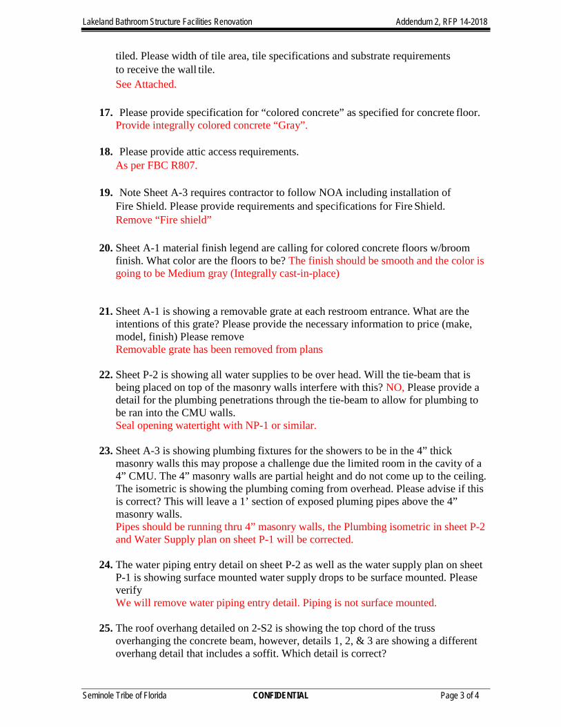
1.3 Soil Survey
The Natural Resources Conservation Services (NRCS) Soil Survey reports
provide a general description of the typical shallow soil strata (about 6 feet) encountered
within each particular soil mapping unit and reports typical depth to seasonal high water
levels. The NRCS defines seasonal high water as “a zone of saturation at the highest
average depth during the wettest season that is at least six inches thick, persists for
more than a few weeks, and is within six feet of the soil surface.” The Soil Survey for
Polk County indicates shallow soils at the site are comprised of Pomona Fine Sand
(map unit 7).

Bryant Road Seminole Reservation Site A
G. Batista and Associates
MEG Project No. 13269
Page 2
According to the NRCS, this Pomona soil is poorly drained on broad areas on
flatwoods. Areas of this soil range from 5 to several hundred acres. Slopes are smooth
to concave and are 0 to 2 percent. Typically, this soil has a very dark gray fine sand
surface layer about 6 inches thick. The subsurface layer to a depth of about 21 inches
is sand. It is light brownish gray in the upper part and light gray in the lower part. The
subsoil to a depth of about 26 inches is dark reddish brown loamy fine sand. Below that
is very pale brown and light gray fine sand to a depth of about 48 inches, light gray fine
sandy loam to a depth of about 60 inches, and light gray sandy clay loam to a depth of
about 73 inches. The underlying material is light gray loamy sand to a depth of at least
80 inches. This Pomona soil is reported to have a seasonal high water table within 12
inches of the surface for 1 to 4 months during most years. The available water capacity
is low. This soil is severely limited as a site for urban development because of wetness.
The absorption fields can be elevated by adding fill material. The high water table
interferes with proper functioning of septic tank absorption fields. To overcome the
problems caused by wetness on sites used for buildings or local roads and streets, a
drainage system can be installed to lower the high water table or fill material can be
added to increase the effective depth to the high water table.
2.0 FIELD EXPLORATION
Madrid explored subsurface conditions at the site on October 9, 2017 by drilling
one (1) Standard Penetration Test (SPT) boring to a depth of 25 feet below ground
surface (bgs), using track mounted drilling equipment. Madrid also completed a Test Pit
to a depth of 30 inches bgs to look for historical indicators of the Seasonal High Water
Table (SHWT). At the base of the test pit, 6-inch long vertical and horizontal Shelby
tubes (relatively undisturbed thin-walled samples) were collected for later permeability
testing in our soils laboratory. The general testing locations were client defined on a
provided map, and were located in the field by measuring from the nearby one-story
residential structure. The residential structure generally faces to the southeast.
Assuming the residential structure faces south, the SPT boring was located 65 feet
north and 20 feet west of the northeast corner of the structure, while the test pit was
located 105 feet north and 20 feet west of the northeast corner of the structure. The
approximate testing locations are shown on Figure 3, Testing Location Map (Client
Provided).
Disturbed samples from the SPT boring were obtained using a split-spoon
sampler in general accordance with ASTM Specification D 1586, using a 1.4-inch I.D.
split-spoon sampler driven with a 140-pound slide hammer falling a distance of 30

Bryant Road Seminole Reservation Site A
G. Batista and Associates
MEG Project No. 13269
Page 3
inches. An engineering technician familiar with soil classification and field evaluations
logged the borings in the field and placed samples in sealed containers and returned
them to Madrid’s laboratory for further classification. Upon completion, the borehole
was backfilled in general accordance with industry standards.
3.0 SUBSURFACE CONDITIONS AND LABORATORY TESTING
3.1 Subsurface Soil Conditions
In general, the SPT boring encountered interbedded layers of very loose to
medium dense sand (SP) and variably silty/clayey sand (SP-SM, SC) from the ground
surface to the boring termination depth of 25 feet bgs. The surficial water table was
encountered at a depth of 36 inches bgs during our field exploration.
The soil boring logs are presented in Appendix A. The general soil profiles
described above and as presented on the boring logs are based on our interpretation of
subsurface conditions encountered at the boring locations only. Boundaries between
soil layers shown are approximate and for illustration purposes only. Variations in soil
conditions in both horizontal and vertical directions different from those presented are
likely to exist at the site.
3.2 Groundwater Conditions and Seasonal High Ground Water
The water table was encountered at a depth of 36 inches (3 feet) bgs during our
field exploration program. Indications of the SHWT were observed within the test pit
(completed in the area of the proposed septic system) at a depth of approximately 6 to 8
inches bgs; thus, we recommend a design seasonal high water table at a depth of 6
inches. This was based upon the location of discernible redox concentrations which
appeared relatively contemporary in nature; and was underlain by a relatively well-
defined region of lower chroma material. No confining layers were encountered within
the depth of exploration.
The Soil Survey for Hillsborough County, Florida describes the seasonal high
water table for the map unit to be within 12 inches of the surface for 1 to 4 months
during most years. The indicators for the SHWT observed during our field program
appear to be consistent with the soil survey mapped unit.

Bryant Road Seminole Reservation Site A
G. Batista and Associates
MEG Project No. 13269
Page 4
3.3 Laboratory Testing
Laboratory tests for natural water content (ASTM D2216) and percent passing
the No. 200 sieve (ASTM D1140) were performed on selected samples from the SPT
boring to verify the visual and tactile soil classifications. Additionally, laboratory testing
for Constant Head Permeability (ASTM D2434) was completed on the horizontal and
vertical Shelby tube samples obtained at depths between 2.5 and 3 feet bgs within the
test pit; and laboratory tests for natural water content and percent passing the No. 200
sieve were performed on the Shelby tube samples after completion of the permeability
tests. Laboratory test reports are included in Appendix B.
� The laboratory tests indicate variable fines contents in sediments at depths
from 2 feet to 15 feet bgs in the SPT boring. Percent passing the No. 200
sieve for SPT samples tested ranges from 5.9 to 39.7 percent. Laboratory
testing completed on the Shelby tube samples indicated between 4.4 and 6.9
percent passing the No. 200 sieve.
� Soils permeability testing yielded a vertical permeability rate of 4.5 in/hr
(11.43 cm/hr) and a horizontal permeability rate of 2.8 in/hr (7.11 cm/hr).
These samples were collected within the test pit completed within the
proposed area for the septic system. The lower horizontal rate appears to be
associated with slightly higher fines content; typically we expect to see
horizontal permeability slightly higher than the vertical.
Discernible redox concentrations
(6 to 8 inches bgs)
Low chroma material

Bryant Road Seminole Reservation Site A
G. Batista and Associates
MEG Project No. 13269
Page 5
4.0 EVALUATION AND RECOMMENDATIONS FOR DESIGN
4.1 General Considerations
The SPT boring encountered very loose to medium dense sand (SP) and
variably silty / clayey sand (SP-SM, SC) from the ground surface to the boring
termination depth of 25 feet. Soil density within the surficial 10 feet bgs were generally
found to increase in density with depth. It is our determination that soil conditions at the
site are suitable for the support of the proposed restroom facility on shallow foundations.
However, construction of foundations should likely be performed in the dry season and
may require dewatering efforts, particularly if constructed during the wet season. If
need be, groundwater levels should be drawn down sufficiently low to permit subgrade
compaction (recommended a minimum of 24 inches below bottom of foundations).
Construction of the foundations should adhere to the structural engineer’s
recommendations and the plans and specifications. Although beyond the scope of this
evaluation, Madrid field personnel indicated that a potable water supply well may be
located within a distance of approximately 50 feet from the proposed location for the
septic system. We note that no measurements between the well and proposed septic
system area were completed by Madrid. However, typically, a distance of at least 100
linear feet is recommended between septic system / drainfield areas and water supply
wells. The designer may wish to re-evaluate the septic system positioning prior to
construction. It is noted that the shallow depth to seasonal water will likely require a
mounded septic system and/or pump station to function correctly.
Based on anticipated loading conditions, inadequate bearing capacity is not
anticipated to be an issue provided our recommendations presented herein are
implemented. The following discussion and recommendations are based on our
understanding of the proposed development, the data obtained from the site
exploration, experience with similar conditions, and generally accepted principles and
practices of geotechnical engineering.
4.2 Restroom Facility Shallow Foundation Analysis and Evaluation
Following site preparation activities, all thickened edge foundations should be a
minimum of 18 inches wide with a minimum depth of foundation of 12 inches below final
grade. Based on the existing soil conditions, and assuming the recommendations
provided are implemented including proof-rolling and compaction criteria presented
subsequently, an allowable soil bearing pressure of 1,700 pounds per foot is
appropriate for existing soil conditions at the SPT boring location. This bearing

Bryant Road Seminole Reservation Site A
G. Batista and Associates
MEG Project No. 13269
Page 6
pressure should result in foundation settlement within tolerable limits (i.e., 1 inch or less
total and with less than ½-inch differential). This assumes no more than 1-foot of fill is
required for general site grading. A slightly higher allowable bearing pressure of 2,000
psf is applicable if the footing embedment is increased to 18 inches.
It should be noted that given the potential variability of subsurface conditions,
limited field and laboratory data, and limitations of the numerical model, settlement
predictions developed by Madrid are approximate. Actual settlements observed during
loading will depend on variations in subsurface conditions.
4.3 Site Preparation
4.3.1 Clearing and Stripping
All development areas should be cleared of any trees, scrub vegetation, existing
debris and organic topsoil stripped as necessary to remove roots and other deleterious
material to the satisfaction of Madrid. Topsoil is anticipated to be on the order of about
6 inches, but may be deeper at isolated locations, and should be discarded or may be
stockpiled for future reuse in landscape areas if desired. In addition, any abandoned
utilities should be removed as open conduits can lead to soil erosion and a loss of
support beneath foundations. Any remnant tree stumps that are encountered during
construction should be removed from within the restroom facility limits.
4.3.2 Proof-Rolling
After clearing and grubbing, the building pad area, including up to 5 feet
horizontally from the plan limits, should be methodically proof-rolled with compaction
equipment or with heavy construction equipment (i.e. large vibratory smooth roller)
capable of achieving the required compaction. Rolling should continue until a density of
at least 95 percent of Modified Proctor Maximum Dry Density (ASTM D-1557) is
achieved over the subgrade areas. Any soft, rolling or otherwise suspect areas should
be investigated and any unsuitable soils and/or unstable soil conditions should be
removed and replaced with structural fill as described in Section 4.3.3.
4.3.3 Earthwork and Compaction
All subgrade soils within 24 inches below building footings should meet gradation
(no more than 12 percent fines or 4 percent organics) and compaction requirements.
This may require excavation and re-compaction. Based on the boring logs, the in-situ
sandy soils (SP, SP-SM) should meet the gradation requirements of no more than 12
percent fines but may require moisture conditioning and compaction to achieve
minimum density requirements. Subgrade soils should be inspected to verify that they

Bryant Road Seminole Reservation Site A
G. Batista and Associates
MEG Project No. 13269
Page 7
meet the gradation and organic content requirements, compacted to at least 95 percent
of the modified Proctor maximum dry density, and tested to verify in-place density to a
depth of 12 inches.
Fill placement should be completed in lifts no greater than 12 inches in thickness
and compacted to at least 95 percent of the modified Proctor maximum dry density. If
compaction cannot be achieved at 12 inch lifts, thinner lifts may be required. Prior to
construction, bulk samples representative of anticipated subgrade and fill soils should
be collected and subjected to Modified Proctor testing as appropriate. Existing sandy
soils may require moisture conditioning to permit adequate compact
5.0 QUALITY ASSURANCE
We recommend implementing a comprehensive quality assurance program to
verify that all foundation construction be conducted in accordance with the
recommendations herein and the appropriate plans and specifications. It is strongly
recommended that Madrid be retained to perform materials testing and inspection
services to observe that the subsurface conditions are as we have discussed herein and
that foundation construction is in accordance with our recommendations. Madrid cannot
accept responsibility for any conditions which deviate from those described in this report
if not engaged to provide construction observation and testing for this project.
6.0 LIMITATIONS
This report has been prepared for G. Batista & Associates for the proposed
restroom facility and associated septic system at the Bryant Road Seminole Tribe of
Florida Reservation Land. The recommendations presented herein are based on
Madrid’s interpretation and understanding of site conditions and other information
provided by the client. This report is intended for use by the designers of this project; it
is not a specification document and is not intended for use as a part of the
specifications. Varying degrees of non-uniformity of the horizontal and vertical soil
conditions are likely to exist between testing locations. Any variations in structure
location or anticipated loading and/or design conditions from those indicated in this
report should be brought to Madrid’s attention as such changes may affect Madrid’s
conclusions and recommendations. The study reported herein has been conducted in
accordance with the generally accepted standards, principles and practices in the
geotechnical engineering profession. No other warranty, expressed or implied, is made.
Madrid is not responsible for the independent conclusions, opinions, and/or
recommendations made by others based on the field investigation data presented in this
report. This study is based on a relatively shallow exploration and is not intended to be
an evaluation for sinkhole potential. This study does not include an evaluation of the

Bryant Road Seminole Reservation Site A
G. Batista and Associates
MEG Project No. 13269
Page 8
environmental (ecological or hazardous/toxic material related) condition of the site or
subsurface.


[_
§̈¦4
§̈¦4
UV33
33
Moo
re
Old
Pol
k C
ity
Tom Costine
Wal
t Will
iam
s
Bry
ant
Cypress Trails
Tom
kow
Pinetop
Fox
Cen
tral
Appa lachian
Pin
econe
Har
tzog
Pin
e Tr
ee
Wilder
Farri
ngton
Country Trails
Foxtown
Abilene
Li
medale
Mal
t ais
EgretCost ine
Hagan
Scand
inavia
Sa nta Fe
Driggers
Ridgegreen
Haynes
Commerce
Church
Pine Glen
Overland
Haymarket
Coyote
Portage
Red River
Orangedale
K ins man
Viking
Odom
Dodge
Gib
s on
Oak
s
Odo
niel
Epicenter
Longhorn
Timber idge
Gra
d y M
ock
Sherwood Lakes
Woodsridge
Nature
Lake
land
Spe
ed
As hbury
Spruce
Mar
gate
Bob W
hite
B ig B end
Lady Bowers
Costine Meadows
Durham
Pineford
Big Ben
Pinebend
Epi
cent
er
Wilder
Epicenter
0 4,000
Feet
4
G. Batista & Associates
MADRID ENGINEERING GROUP, INC.
Sources: GIS Information (ESRI)
FIGURE 1Location MapSeminole Reservation Site ALakeland, Florida
Drawn By: BJN Checked By: JED
MEG Project Number
13269 Notes:
2030 State Road 60 EastBartow, Florida 33830863 533-9007 Fax: 863 533-8997EB-0006509
Lakeland,Polk County

[_7
7
6
7
7
9
33
17
6
6
33
9
6
6
32
59
1715
6
69
14
13
32
7
4
26
6
6
32
32
9
9
9
9
6
15
32
6
6
6
6
40
17
14
99
47
25
25
6
36
32
17
6
33
336
59
7
13
59
59
33
36
6
6
36
99
25
0 1,000
Feet
4
G. Batista & Associates
MADRID ENGINEERING GROUP, INC.
Sources: GIS Information (ESRI)
FIGURE 2NRCS/USDA Soils MapSeminole Reservation Site ALakeland, Florida
Drawn By: BJN Checked By: JED
MEG Project Number
13269 Notes:
2030 State Road 60 EastBartow, Florida 33830863 533-9007 Fax: 863 533-8997EB-0006509
LegendSoilsmusym, MUNAME
13, SAMSULA MUCK
14, SPARR SAND, 0 TO 5 PERCENT SLOPES
15, TAVARES FINE SAND, 0 TO 5 PERCENT SLOPES
17, SMYRNA AND MYAKKA FINE SANDS
25, PLACID AND MYAKKA FINE SANDS, DEPRESSIONAL
26, LOCHLOOSA FINE SAND
32, KALIGA MUCK
33, HOLOPAW FINE SAND, DEPRESSIONAL
36, BASINGER MUCKY FINE SAND, DEPRESSIONAL
4, CANDLER SAND, 5 TO 8 PERCENT SLOPES
40, WAUCHULA FINE SAND
47, ZOLFO FINE SAND
59, ARENTS-URBAN LAND COMPLEX, 0 TO 5 PERCENT SLOPES
6, EATON MUCKY FINE SAND, DEPRESSIONAL
7, POMONA FINE SAND
9, LYNNE SAND
99, WATER


MADRID ENGINEERING GROUP, INC. 2030 State Road 60 East
Bartow, Florida 33830
(863)533-9007 FAX: (863)533-8997
Project Number: 13269 Date Tested:
Project Name: Seminole Reserve Site A Tested By:
Project Location: Lakeland, Florida
Client: G. Batista & Associates Page 1 of 1
SPT-1 2-4' 117 135.49 115.70 7.66 84.5% 18.3% 109.37 5.9%
SPT-1 13.5-15' 110 172.28 149.24 7.66 86.0% 16.3% 93.10 39.7%
10/12/2017
WG
ASTM C117-13 MOISTURE / PERCENT < No. 200 SIEVE
WC+SW
(g)
WC+SD
(g)
WC
(g)
Solids
Content
(%)
Moisture
Content
(%)
WC+SR
(g)
<#200
(%)Sample
Cont.
Name
Retained Sample of WeightS
SampleDry of WeightS
Sample Wetof WeightS
Container of WeightW
R
D
W
C
=
=
=
=
( )SS
100S
W(%) Content Moisture
100S
S(%) Content Solids
D
OH
W
D
2*
*
−
=
=
Your FULL SERVICE Geotechnical Partner!
MBE/DBE/SBE -- Geotech -- CEI -- Drilling -- Soils/Materials Testing Labs
www.madridengineering.com

MADRID ENGINEERING GROUP, INC. 2030 State Road 60 East
Bartow, Florida 33830
863/533-9007 FAX: 863/533-8997
Project Number: 13269 Date Tested: 10/13/2017
Project Name: Seminole Reserve Site A Tested By: Doug P.
Project Location: Lakeland, FL
Client: G. Batista& Associates
Boring Number: TP-1 Vertical Sample Interval: 2.5' - 3'
Soil Description: Gray sand USCS Code: SP
< #200 sieve: 4.4 %
Post-Test Moisture (From -200): 19.1 %
1232.85 g Natural Moisture: 16.1 %
1264.98 g
1062.12 g
Diameter of Permeameter: 7.30 cm
Height of soil in Permeameter: 14.96 cm
Area of soil in Permeameter: 41.85 cm2
Post-Test Unit Weight of soil: 2.02 g/cm3 126.1 pcf (post-test)
122.9 pcf (in-situ)
Permeability determination 105.9 pcf (dry)
Length of soil in Permeameter, l : 14.96 cm
Cross sectional Area, A : 41.85 cm2
1 3.5 62.75 1800 25.7 3.56E-03 0.8893 0.23395722 8.33E-04
2 4 73.09 1800 25.7 3.63E-03 0.8893 0.26737968 9.70E-04
3 4.5 82.56 1800 26.1 3.64E-03 0.8694 0.30080214 1.10E-03
4 5 93.05 1800 26.1 3.70E-03 0.8694 0.3342246 1.24E-03
5
Average Permeability: 3.19E-03 cm/s 4.5 in/hr
Weight of soil dry:
ASTM D2434-68 CONSTANT HEAD PERMEABILITY
Unit weight determination
Weight of in-situ soil:
Weight of post-test soil:
Sample Density
Trial No.Head, h
(cm)
Flow,
Q out
(cm3)
Time, t
(s)
Temp, T
(°C)
Permeability
at T , k T
(cm/s)
Ratio of
Viscosity,η
η T :η 20°C
3.21E-03
Hydraulic
Gradient, i
Velocity, v
(cm/sec)
Permeability at 20°C,
k 20°C
(cm/s)
3.17E-03
3.23E-03
3.17E-03
0
0.05
0.1
0.15
0.2
0.25
0.3
0.35
0.4
0.E+00 2.E-04 4.E-04 6.E-04 8.E-04 1.E-03 1.E-03 1.E-03
Hy
dra
uli
c G
rad
ien
t, i
Velocity, v (cm/sec)
Verification of Laminar Flow Regime
Your FULL SERVICE Geotechnical Partner!
MBE/DBE/SBE -- Geotech -- CEI -- Drilling -- Soils/Materials Testing Labs
www.madridengineering.com

MADRID ENGINEERING GROUP, INC. 2030 State Road 60 East
Bartow, Florida 33830
863/533-9007 FAX: 863/533-8997
Project Number: 13269 Date Tested: 10/13/2017
Project Name: Seminole Reserve Site A Tested By: Doug P.
Project Location: Lakeland, FL
Client: G. Batista & Associates
Boring Number: TP-1 Horizontal Sample Interval: 2.5' - 2.5'
Soil Description: Very Dark Grayish Brown sand USCS Code: SP-SC
< #200 sieve: 6.9 %
Post-Test Moisture (From -200): 30.4 %
1141.57 g Natural Moisture: 24.2 %
1198.38 g
919.00 g
Diameter of Permeameter: 7.31 cm
Height of soil in Permeameter: 15.29 cm
Area of soil in Permeameter: 41.97 cm2
Post-Test Unit Weight of soil: 1.87 g/cm3 116.6 pcf (post-test)
111.1 pcf (in-situ)
Permeability determination 89.4 pcf (dry)
Length of soil in Permeameter, l : 15.29 cm
Cross sectional Area, A : 41.97 cm2
1 3.5 38.7 1800 25.7 2.24E-03 0.8893 0.22890778 5.12E-04
2 4 44.59 1800 25.7 2.26E-03 0.8893 0.26160889 5.90E-04
3 4.5 50.63 1800 26.1 2.28E-03 0.8694 0.29431001 6.70E-04
4 5 57.69 1800 26.1 2.34E-03 0.8694 0.32701112 7.64E-04
5
Average Permeability: 2.00E-03 cm/s 2.8 in/hr
Weight of soil dry:
ASTM D2434-68 CONSTANT HEAD PERMEABILITY
Unit weight determination
Weight of in-situ soil:
Weight of post-test soil:
Sample Density
Trial No.Head, h
(cm)
Flow,
Q out
(cm3)
Time, t
(s)
Temp, T
(°C)
Permeability
at T , k T
(cm/s)
Ratio of
Viscosity,η
η T :η 20°C
2.03E-03
Hydraulic
Gradient, i
Velocity, v
(cm/sec)
Permeability at 20°C,
k 20°C
(cm/s)
1.99E-03
2.01E-03
1.98E-03
0
0.05
0.1
0.15
0.2
0.25
0.3
0.35
0.E+00 1.E-04 2.E-04 3.E-04 4.E-04 5.E-04 6.E-04 7.E-04 8.E-04 9.E-04
Hy
dra
uli
c G
rad
ien
t, i
Velocity, v (cm/sec)
Verification of Laminar Flow Regime
Your FULL SERVICE Geotechnical Partner!
MBE/DBE/SBE -- Geotech -- CEI -- Drilling -- Soils/Materials Testing Labs
www.madridengineering.com


SILT FENCE LAYOUT
N
SITE PLAN LEGEND
SHEET#
EN
GIN
EE
RIN
G - C
ON
ST
RU
CT
IO
N
DA
VIE
, F
L 33314
96
10
B
RY
AN
T R
OA
D
LA
KE
LA
ND
, F
L 3
38
09
SIT
E P
LA
N
Top Related