


Languages
Pages
Legal

SELF-RIGHTING BOAT DESIGN 41
Sayı 6, 2016 GiDB|DERGi
SELF-RIGHTING BOAT DESIGN
Hakan Akyıldız, Cemre Şimşek
Istanbul Technical University | [email protected]
ABSTRACT
The stability behavior of small craft is of great importance at very high angles of heel, up to the
completely inverted condition. The fundamentals of stability in the design of yachts and other small craft
is considered, and the significance of our current understanding is reviewed based on static stability
analysis.
There are three main self-righting methods examined in this study. These are; inherent self-righting
method, inflatable bag method and moveable ballast method. All of them have their advantages and
disadvantages. Inflatable bag is easy to apply and maintenance, but there are very small area of
applicability and does not ensure safety of the crew. Moveable ballast method practically applicable only
for small craft and maintenance of mechanical components is hard. On the other hand, it can be designed
to be self-operating system and fitted to small open boats where buoyant superstructure is not a feasible
option. Although designing inherently self-righting craft is challenging due to the difficulty of weight
distribution’s uncertainty during the design process, it is the best option for any self-righting vessel.
Keywords: Self-Righting methods, Self-Righting stability, Capsizing.
1. Introduction
Regardless of the type of floating structure that is being designed, one of the designer’s main
tasks is to ensure the safety and seaworthiness of the structure, a prime consideration being the
safety against capsizing. Despite recent advances in ship hydrodynamics, the possibility with a
good measure of confidence, and in fact relatively little attention has been paid to the
mechanism of capsizing.
The solution of the ship capsizing problem is one of the major challenges that scientist and
naval architects have to meet. The problem is as old as shipbuilding itself. It concerns ship
operators and designers and has preoccupied researchers’ attention for many years. Capsize
disasters are so painful, not only because of material losses, but primarily because they take
human lives.
It is not strange, therefore, that the matter is raised and discussed so frequently. It is amazing,
however, how little progress is being made despite the considerable amount of research that has
been carried out in this field worldwide.
At present, there is no scientifically based stability safety criterion, and there is no mathematical
model of ship capsizing in the general case of operation in extreme waves.
Two predominant approaches to the ship capsizing problem can be observed at present. One of
them is based on the classical assessment of stability safety by analysis of the righting moment
42 Y.A. SOYADI, Y.A. SOYADI, Y.A. SOYADI ve Y.A. SOYADI
GiDB|DERGi Sayı 6, 2016
curve in comparison with external, usually stipulated, heeling moments. The major efforts are
focused either on establishing requirements for the shape and values of the GZ curve (calculated
in calm water or on a wave crest) so that a required safety level can be maintained during ship
operations in unspecified sea conditions, or on establishing the nominal heeling moments which
the ship has to withstand (statically or dynamically or both) [1].
The required safety standards are usually a result of a detailed stability analysis of a particular
type of ship or some statistical studies of safe ships and casualties, and reflect so-called “good
marine practice.” They may provide a reasonable safety level for some classes of ships or some
operational situations but in other cases they are not satisfactory or fail completely.
The second trend represents efforts to base the stability criteria on more sound theoretical
models. However, the studies are focused on some selected simplified cases which are related to
ship behavior either in beam or following seas. Although the selected situations are realistic,
they do not represent he most severe scenarios of ship operation in oblique extreme seas, and
none of the proposed approaches is general enough to represent the whole range of phenomena
affecting ship stability.
2. Desıgn And Stabılıty Objectıves
Many competing requirements of the design of small craft such as minimum resistance and
windage, adequate power from engine and sails, sufficient strength and structural redundancy,
low weight, maximum comfort below and protection on deck, good aesthetics, and reasonable
costs, are all objectives that the designer has to balance in order to achieve a compromise
solution. Adequate stability is also a requirement of every boat design.
Ships are designed on the basis that capsize must be prevented, and its occurrence is considered
a catastrophe that will inevitably lead to the loss of the vessel, and in all probability the loss of
life. This approach cannot be taken with small craft. On many occasions the energy available in
the environment in which the craft is operating is overwhelmingly greater than the work
required to capsize the vessel, and so the designers of small craft have to countenance this
possibility and design accordingly [2].
2.1 Ship Stability Basis
An understanding of the fundamentals of stability was established by Bouguer in 1746, and
independently by Euler in 1749 [3], since when research has continued around the world into
many complex and subtle developments of stability theory [4]. However it is only in the small
craft world that stability at all angles of heel, including 180 degrees, is of crucial concern. Since
1980, and as a result of actual or near disasters, there has been much research undertaken into
the stability of yachts and small craft at all angles of heel. The availability of economical
stability modelling programs for PCs since the mid 1980s has greatly facilitated the exploration
of high angle stability, both in a research and design context, so that now the behaviour of
vessels in the inverted state is widely understood [2].
Ships are designed for stability when the vessel is operating normally and upright, but also to
design for instability in the crisis situation where the vessel is inverted and we want it to rapidly

SELF-RIGHTING BOAT DESIGN 43
Sayı 6, 2016 GiDB|DERGi
capsize back to the upright condition again. It is also intended that this exploration of the idea
will enhance the understanding of the impact of stability considerations on the design of all
small craft, and enable stability to be considered at the earliest stages of the design process.
The International Maritime Organisation (IMO) has set out criteria [5] which have been
implemented in national legislation in most countries, but for small craft there are often other
bodies (such as the MSA and RYA in the UK) that have developed more relevant standards and
codes. The stability behaviour of a vessel at sea is highly complex, and the static stability
diagram which plots the righting lever (GZ) against heel angle, can not model such phenomenon
as surfing, broaching, and parametric rolling. However it does capture many of the key stability
characteristics of a vessel, and can be used as a remarkably powerful analysis tool.
In a design for stability exercise any of these criteria could be used as objectives, in which case
the design task would be to achieve a static stability curve that had certain attributes, defined in
terms of minimum values for the following: the initial stability (GM), the range of stability, the
reserve stability (proportional to the area under the curve), and for the value and heel angle of
GZmax (Figure 1).
Figure 1. Statical stability curve
However, capsize is still considered to be an event to be avoided and that there is no guidance as
to the relevant criteria for the stability of the vessel in the inverted state, once capsize has
occurred. For a craft to be automatically self righting there must be positive stability at all
angles of heel. If this is the objective then the criteria for the inverted state (heel angles greater
than 90 degrees) should be that GZ must be greater than zero. However if assumptions are made
as to the stability challenges the inverted craft will be subjected to (waves, wind, human
intervention), then we could propose other limiting values for this condition also, such as
maximum value and angle of occurrence of the negative GZmax and maximum value of reserve
stability in the inverted state[2].
The criteria give us minimum values from the perspective for safety. In a design for stability
process, high values of GZ at small angles of heel result in an excessively stiff vessel with sharp
Angle of max.
stability
Range of stablity
GM
GM GMsin
GMsin+1/2BMtan2sin
Deck edge
immersion
B
C GZmax
φ D
Angle of
vanishing
stability
57.30=1 rad
GZ
44 Y.A. SOYADI, Y.A. SOYADI, Y.A. SOYADI ve Y.A. SOYADI
GiDB|DERGi Sayı 6, 2016
motions, and high values at very large angles of heel (above 90 degrees) result in a violent
righting action. The combined requirements of safety and comfort suggest that it should be
possible to define an ideal GZ curve, or more realistically an acceptable stability envelope, with
minimum values defined by the safety criteria, and maximum values by reference to acceptable
motions. It can be proposed the probable form of a stability envelope intended to be used as a
design objective [2]. If the objective of a design for stability exercise is to create a vessel that
has a GZ curve that lies within a defined envelope, then we have to be able to directly control
the shape of the curve. Analysis of the stability of a vessel based on the righting lever arm over
the entire range of angles of heel, the GZ curve, has its limits. Despite the limitations of
parametric rolling, surf riding, broaching, effects of heave accelerations on the righting moment
and the impact of a wave waterline on the behavior of the vessel, it is a valuable model of many
aspects of the behavior of a vessel and the sufficiency of the stability of all types of craft.
Reserve stability can be evaluated though a curve of righting arms, also called stability curve,
which plots the righting arm GZ, against heel angle. As long as GZ is positive, the boat will
self-right. At the angle the GZ turns negative, the boat will capsize. This shows immediately as
the range of stability. The curve also shows other important things. The area under the positive
portion of the righting arm curve represent the energy required to capsize the boat. The more
energy required, the stronger the wind gust and the more sustained it must be to create a capsize.
Alternately, the bigger and faster moving the wave must be to capsize the boat. Similarly, the
area under the negative side of the curve represents the energy required to re-right a boat once
it’s been capsized.
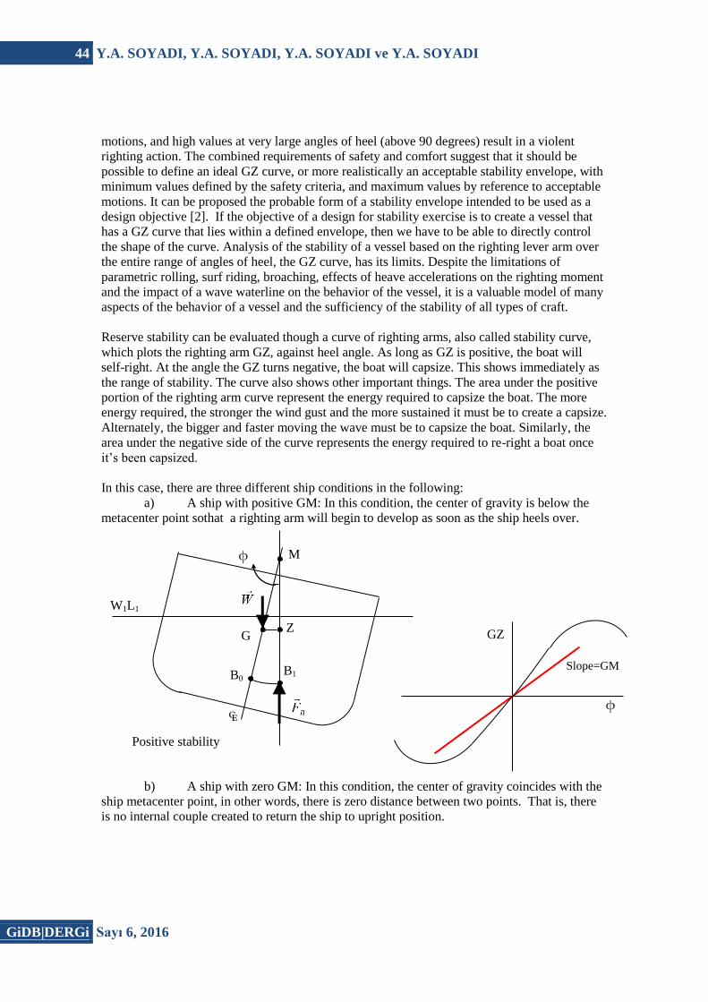
In this case, there are three different ship conditions in the following:
a) A ship with positive GM: In this condition, the center of gravity is below the
metacenter point sothat a righting arm will begin to develop as soon as the ship heels over.
b) A ship with zero GM: In this condition, the center of gravity coincides with the
ship metacenter point, in other words, there is zero distance between two points. That is, there
is no internal couple created to return the ship to upright position.
Slope=GM
φ
GZ
φ
W1L1
₠
M
B1 B0
G Z
Positive stability

SELF-RIGHTING BOAT DESIGN 45
Sayı 6, 2016 GiDB|DERGi
c) A ship with negative GM: In this condition, the center of gravity is above its
metacenter point. The slope of the righting arm curve is negative at zero degree heel.
Figure 2. Ship’s Stability Conditions
2.2 Self – Righting Stability
Self-righting stability is an old term in naval architecture history but, it is relatively new
practical concept. On any self-righting vessel, GZ curve does no turns negative throughout 360°
of roll cycle.
All traditional boats have a heel angle which righting levers have degraded to zero. This term is
defined as Point of Vanishing Stability. Frequently, this point does not occur until ship is
completely inverted, but for those have enough buoyancy to stay afloat, any heel angle beyond
Slope= GM=0 φ
GZ
W1L1
₠
M
B
G
Neutral stability
Z
Slope= GM
φ
GZ
W1L1
₠
M
B
G
Negative stability
46 Y.A. SOYADI, Y.A. SOYADI, Y.A. SOYADI ve Y.A. SOYADI
GiDB|DERGi Sayı 6, 2016
Point of Vanishing Stability will result in rotation until equilibrium is maintained. With this
attitude ship can be more stable when upright.
In order to achieve a self-righting design, the vessel must fill three fundamental requirements
[6]:
Possess a curve of righting levers for which there is no Point of Vanishing Stability
which possible with positive GZ curve throughout the full 360 degrees’ rotation.
Become unstable when inverted to initiate the righting process until vessel become
upright position.
Remain buoyant and watertight.
3. Self-Righting Methods
To provide the criteria mentioned above, self-righting craft usually own a non-flooding hull and
sufficient buoyancy suitably placed to ensure that the vessel is unstable when inverted. In case
of large vessels size of superstructure generally produce adequate buoyancy, with all hull and
opening being non-flooding or self-closed to keep watertight integrity. Such vessels have
inherently self-righting the capability is in the design. For small boats, lacks of space for large
superstructure usually prevent inherited self-righting ability. In order to achieve self-righting use
of inflatable bag can be used. Inflatable bag can be either triggered automatically or manually
by crew when vessel is capsized. Third method is the moveable weight method called
commonly water ballast. Moving weight causes an instability when ship is capsized resulting a
positive righting moment.
Neither inflatable bag nor moving weight prevents capsizing. This methods used after passing
the point of vanishing stability to ensure instability until ship is come to its upright position.
After that normal form and stability criteria comes into play.
One essential of any self-righting vessel is the relationship between weight and buoyancy to
obtain required stability curve. One achieved this curve in rolling process; nothing should
disturb it and impaired the recovery process. Meaning that, crew, passengers, and equipment
should not move and change the ship’s center of gravity. Thus, securing the crew and
passengers is also an important criterion for self-righting vessel design.
3.1 Inherent Self-Righting
Boats utilizing this method have their self-righting ability where it is always available and will
return upright from any angle of heel regardless of crew’s additional action.
SELF-RIGHTING BOAT DESIGN 47
Sayı 6, 2016 GiDB|DERGi
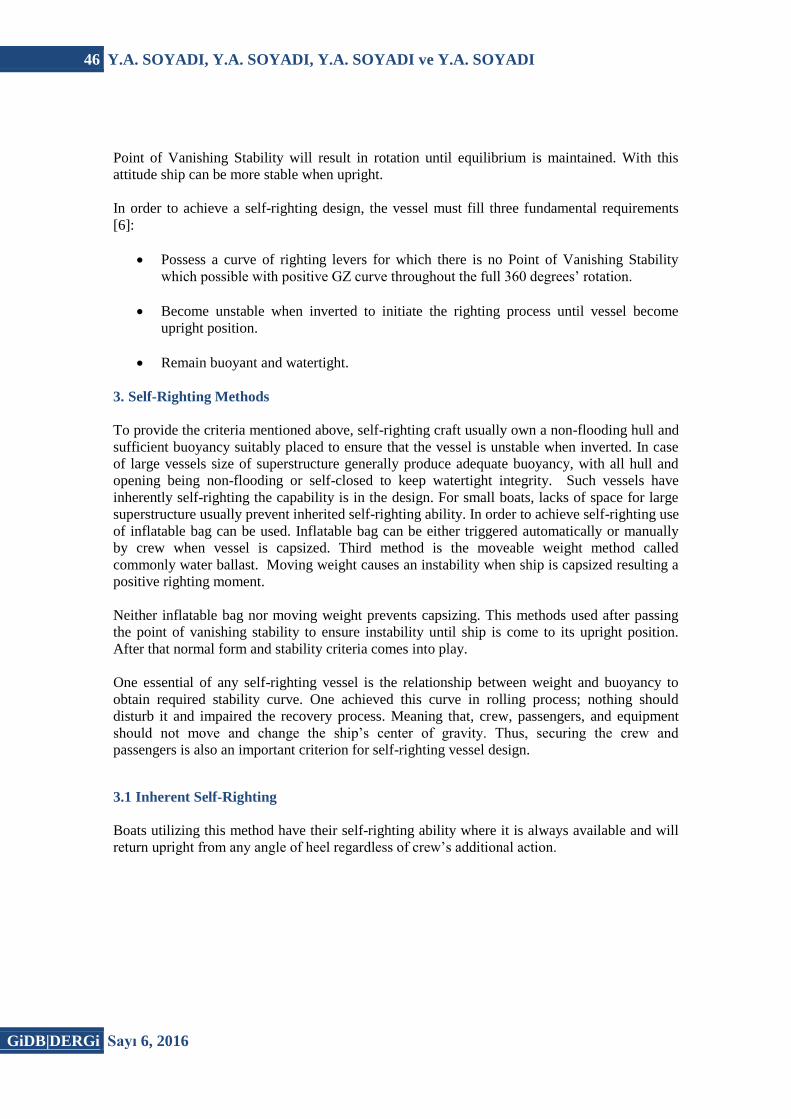
Figure 3. Examples of Inherently self-righting boats.
Vital quality of this craft is heaving a watertight hull and mainly watertight superstructure.
Strategically located weight and buoyancy distribution is key to achieving inherent self-righting.
Ship’s main machinery system usually located at aft deck. Thus, in case of capsizing; trimming
due to the weight and buoyancy difference must avoid. An extra lift force is required to avoid
negative stability curve when the vessel immersed at the aft deck (Fig. 3).
Benefits of inherent self-righting include [6]:
No working parts that could go wrong
Self-righting capability is always available and at any angle of heel, so can prevent full
capsize of the vessel.
Can, within reason, be applied to any size vessel, although weight limitations on very
small can limit effectiveness.
Disadvantages of the method include [6]:
Superstructure volume must be adequate to provide the necessary inverted buoyancy,
which often results in the seemingly oversize deckhouse fitted to modern rescue boats.
All hull and superstructure opening must self-close or remain above the waterline
during full 360 degrees roll.
Structure of hull and superstructure, including any deck recesses, must be designed to
withstand hydrodynamic forces resulting from capsize.
Window and doors must be capable of withstanding the same pressures as hull and
superstructure.
A good effective mechanical ventilation system will be necessary as the vessel will
effectively be operating closed down with all doors and windows shut.
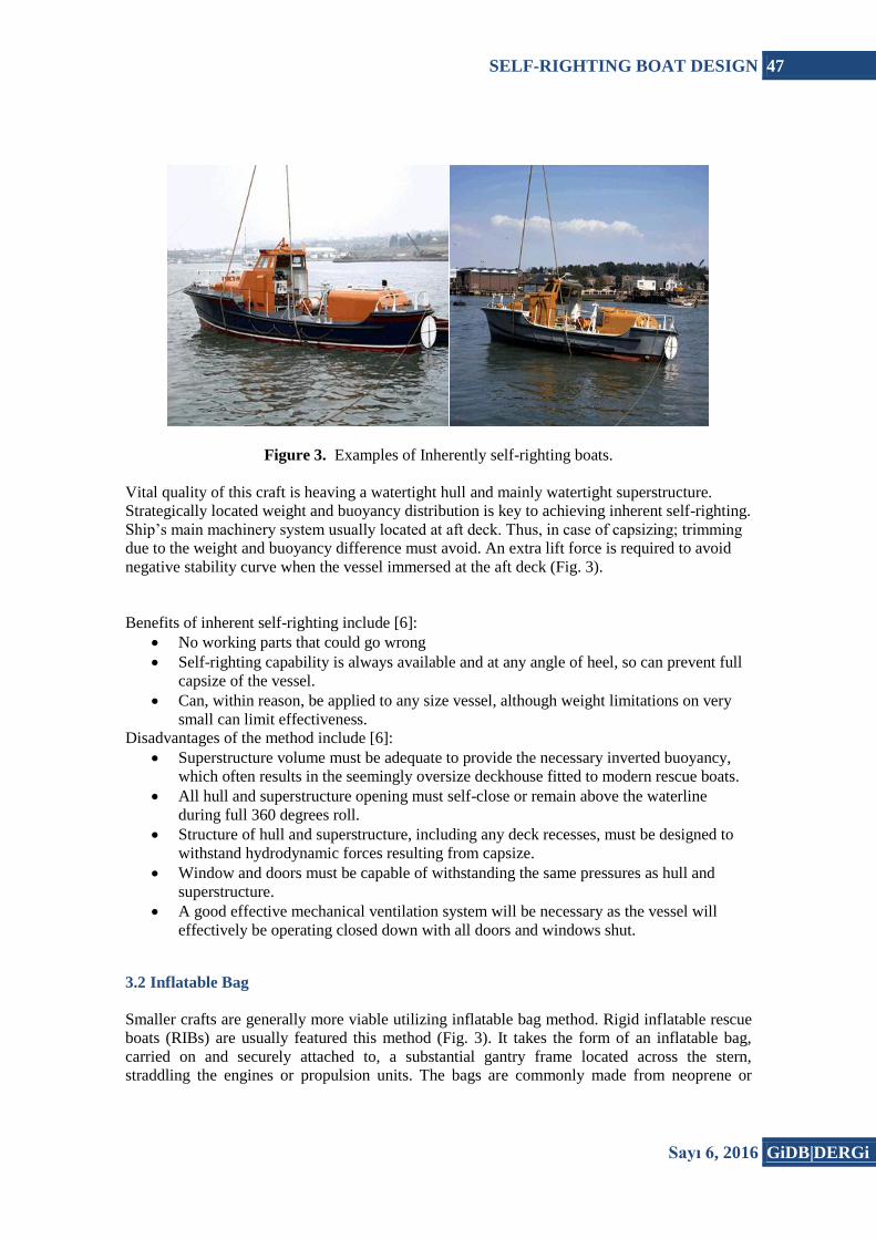
3.2 Inflatable Bag
Smaller crafts are generally more viable utilizing inflatable bag method. Rigid inflatable rescue
boats (RIBs) are usually featured this method (Fig. 3). It takes the form of an inflatable bag,
carried on and securely attached to, a substantial gantry frame located across the stern,
straddling the engines or propulsion units. The bags are commonly made from neoprene or
48 Y.A. SOYADI, Y.A. SOYADI, Y.A. SOYADI ve Y.A. SOYADI
GiDB|DERGi Sayı 6, 2016
hypalon coated fabric, similar to that used in manufacture of inflatable boats and are inflated
using compressed gas infected under pressure. The gas canister is usually fired manually from
the inverted vessel and has attached them to a tether line running from the stern. This keeps
crew in contact with the boat before, during and after righting. To fire the bag automatically
with personnel still underneath could result in injury and, in strong winds, the upright vessel
being blown away from the crew before they can re-board. Automatically activated inflatable
bags are occasionally fitted on vessels where the wheelhouse volume provides insufficient
buoyancy to effect satisfactory and reliable self-righting.
Benefits of the inflatable bag method include [6]:
Simple and light weight.
Volume can be adjusted by changing the size of airbag.
Easy maintenance as bag can be removed and replaced with a substitute.
Disadvantages of the inflatable bag include [6]:
Bag must be fitted and folded correctly to achieve reliability.
Roll bar structure and bag attachment must be substantial to resist the forces present
during the righting process, particularly at 90 degrees heel.
Provides a once only righting ability. Some boats are fitted with duplicate gas cylinders
for 100% system redundancies and to provide a second inflation, should this be
necessary, but the bag is not repacked between firings.
Bag liable to damage if inflated in shallow water or close to a casualty.
Gas pipework and bag injection point must be correctly designed to avoid freezing.
Figure 4. Inflatable self-righting bag on a rescue boat.
SELF-RIGHTING BOAT DESIGN 49
Sayı 6, 2016 GiDB|DERGi
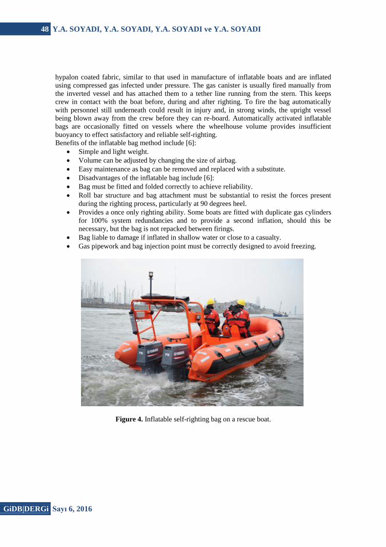
Figure 5. Oakley 37 self-righting
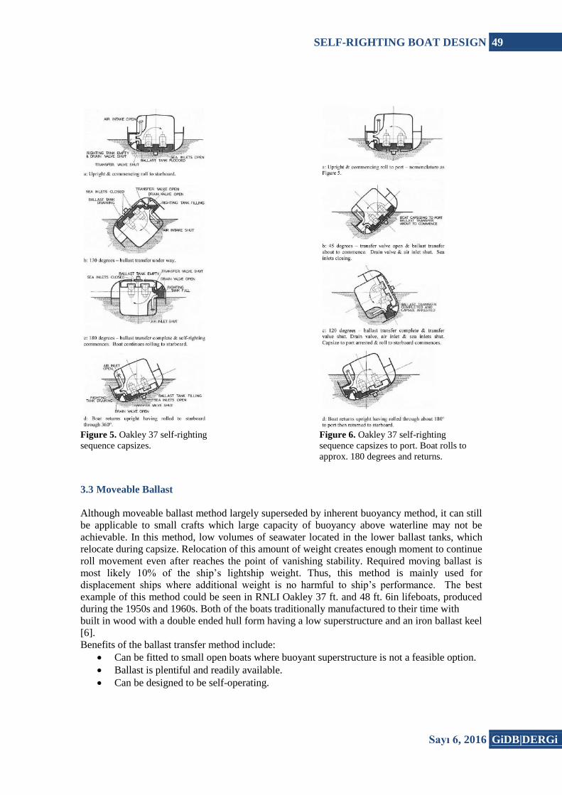
sequence capsizes. Figure 6. Oakley 37 self-righting
sequence capsizes to port. Boat rolls to
approx. 180 degrees and returns.
3.3 Moveable Ballast
Although moveable ballast method largely superseded by inherent buoyancy method, it can still
be applicable to small crafts which large capacity of buoyancy above waterline may not be
achievable. In this method, low volumes of seawater located in the lower ballast tanks, which
relocate during capsize. Relocation of this amount of weight creates enough moment to continue
roll movement even after reaches the point of vanishing stability. Required moving ballast is
most likely 10% of the ship’s lightship weight. Thus, this method is mainly used for
displacement ships where additional weight is no harmful to ship’s performance. The best
example of this method could be seen in RNLI Oakley 37 ft. and 48 ft. 6in lifeboats, produced
during the 1950s and 1960s. Both of the boats traditionally manufactured to their time with
built in wood with a double ended hull form having a low superstructure and an iron ballast keel
[6].
Benefits of the ballast transfer method include:
Can be fitted to small open boats where buoyant superstructure is not a feasible option.
Ballast is plentiful and readily available.
Can be designed to be self-operating.

50 Y.A. SOYADI, Y.A. SOYADI, Y.A. SOYADI ve Y.A. SOYADI
GiDB|DERGi Sayı 6, 2016
Ballast can be used to enhance upright stability.
Disadvantages of ballast transfer method include:
High number of mechanical components such as self-operating valves requires
maintenance to ensure 100% reliability.
Quantity of ballast water might restrict application and size of vessel.
Not viable for planning craft where the additional weight would limit performance.
Planning craft also have the difficulty of keeping water ballast in the tank whilst under
way.
Vessel structure must be designed to withstand continuous immersion in seawater. The
RNLI Oakley 37 was always kept ashore as incompatible materials used in the ballast
tank construction quickly corroded if left afloat(Figs. 4-5).
System can result in vessel being recovered in one direction irrespective of capsize.
4. Self – Righting Testing Methods
Determining the buoyancy locations are vital on any self-righting vessel design. For methods
like inflatable bad and moveable ballast, there may not much choice. However, when designing
an inherently self-righting craft, hull form, superstructure geometry and distribution of weight
play utmost importance. Since, stability data comes late in design process in traditional ship
design, naval architect should pay attention to buoyancy locations.
In today’s technology, computer programs help to realize any mistake made in early design
process but in order to avoid repetitive calculations, stability data should be produced carefully.
There are several ways to analysis design’s self-righting ability. Mainly, they could be grouped
as, computer modelling and analysis, model testing.
4.1 Model Testing
Model testing is the most powerful investigation method of any self-righting craft. It is mainly
categorized as static model testing and dynamic model testing.
In static model testing, small models are used to investigate the self-righting behavior of design.
Different loading situations are examined to check calculated data. In order to create these
situations ballast water and loading cells are used.
In this process, static model must prepare very carefully. Hull form and superstructure geometry
should meet to required scaling effects. Model needs to be completely watertight and possess all
external features of original design.
In example of search and rescue boats where, self-righting is mostly used, survivors that taken
onboard on rough sea conditions change the center of gravity of vessels. This kind of weight
changes may not be modelled even on the most powerful engineering software. In this type of
situations static model testing is the best reliable method of all self-righting methods.
Simulation of capsizing is recorded via video. So, after static model testing completed designers
could watch the video on slow motion and determine the real ship’s behavior under those
SELF-RIGHTING BOAT DESIGN 51
Sayı 6, 2016 GiDB|DERGi
conditions. Differences need to be taken into account, because real life sea conditions could not
properly modelled. It is basically up to the designer’s skills.
For vessels that operating in rough sea conditions such as search and rescue boats, prediction of
characteristic behavior of the vessel is crucial. Cost of prototype is considerably high for rescue
vessels, so before executing prototype it is essential to see how ship will handle severe sea
conditions. Dynamic model testing is the method for estimating that behavior.
Traditional towing tank experiments are very similar to dynamic model testing method. In
towing tank test, non-powered hull is pull in the water. Even so, it is a good way to examine
bow wetness, model does not expose to any other wave headings.
Dynamic model testing carried out with self-propelled model in open sea environment. Unlike
towing tank experiments, this time model experience several wave heading at once. Although
superstructure of model geometrically not as important as it was in static model testing, in order
to protect propulsion system, superstructure should be watertight. Also, superstructure weight
should distribute as in real design. Then the model can be directed to encounter waves from all
headings considering capsize, broach and knock-down.
4.2 Computer Modelling and Analysis
With the recent technological development computer programs are fairly helpful to a Naval
Architect for stability analyze in early design process. Modelling software enables to test
different effective hull forms and superstructure geometry. In order to properly model a
self-righting craft, software must be able to analyze 180 degrees of roll to starboard and 180
degrees of roll to port. Additionally, software should manage asymmetrical superstructure
geometry computation like many rescue boats have in their design. Also, modelling the true
shape of design is critically important since any buoyancy location have large impact on self-
righting ability on the vessel. Buoyancy sections that are not included on main superstructure
body such as mast volume also should be computed on that software.
Computation of weight and centers are standard practice for any ship design. But, weight and
weight distribution have utmost importance in any self-righting craft. Even a slight change in
weight or weight centers could cause negative GZ curve. Computer software should calculate
these weight centers on high accuracy. Any increase in Vertical center of gravity (VCG), also
could change the stability curve and cause negative righting levers. Naval architect should have
always checked and updated weight calculations as design and construction progress.
When construction is finished, an inclining test is carried out to determine the accurate center of
gravity and verify the calculations.
5. Design Criteria
In general, design and outfit requirements for self-righting vessels differ little from those of
conventional craft of similar size and function. There are, however, a few areas requiring special
consideration.

52 Y.A. SOYADI, Y.A. SOYADI, Y.A. SOYADI ve Y.A. SOYADI
GiDB|DERGi Sayı 6, 2016
The craft’s weight and center of gravity limits are based on a hoisting weight, speed, stability
and seakeeping requirements. The maximum allowable center of gravity is mostly limited by the
wind heel criteria. [7].
The structural design of a high speed, self-righting, rescue boat presents some unique problems.
As with any high speed craft, the designer is faced with seeking an appropriate balance between
craft weight limits and structural integrity under the expected operating conditions and service
life. The extreme operating environment, severe mission demands and extended annual
operating hours for crafts make achieving an appropriate balance a challenging task. As a
general design of high speed craft is based on the idea that the structural design limit exceeds
the crew’s ability to sustain the maximum expected craft motions. Even though determining the
crew’s operational limits is subjective some reasonable assumptions can be made. However, in
the case of heavy weather motor lifeboat operational limits are at best uncertain. In the surf
rescue motion and the magnitude of the loads on the craft are now well known or predictable.
An overly conservative design approach might be indicated owing to the uncertainty but, the
weight constraints required for high speed performance necessitates a weight conscience
structural design approach.
Key design considerations in the coupling and shafting arrangement included minimizing the
coupling joint angles to maximize reliability and locating the engines and gears low in the hull
to reduce the KG and increase stability. The parallel arrangement of shaft configuration usually
favored because it offers substantial benefits with respect to producibility and alignment.
The heating, ventilation and air conditioning (HVAC) system is required to maintain
temperatures between 13°C and 27°C in enclosed bridge and 26°C to 27°C in the survivor’s
compartment with external air temperatures ranging from -12°C to 37°C. The systems use direct
expansion Freon with reverse cycle heating. While the design is relatively conventional,
requirements for self-righting and the need to avoid progressive flooding in a damaged
condition present special design considerations. Much like the engine air intake, the design of
HVAC intakes and exhausts require special attention at various roll angles.
With watertight integrity essential for vessel safety, all doors. Hatches and windows fitted to
self-righting craft must be capable of resisting the hydrostatic forces associated with capsize. In
addition, most will be fitted in compartments or spaces used as part of the vessel’s watertight
subdivision, so could be required to keep water in as well as out. All doors, hatches and
windows fitted to self-righting craft must therefore be as strong as the adjacent structure and
capable of accepting hydrostatic pressure from either side. No door, hatch or window can be
expected to do its job of keeping water out if not securely closed, so to minimize the risk to
vessel safety, all should be kept shut at sea unless actually being used. Those that do need to be
opened regularly for crew access to other parts of the vessel, such as wheelhouse doors onto the
deck, should remain open for the shortest possible time and must consequently be quick and
easy to operate with a positive and secure locking mechanism. Wheelhouse doors on rescue
vessel are often located facing aft to protect them from direct wave impact. Even modern
lightweight composite doors can inflict serious injury when driven by a heavy roll, so it is
important to provide grab rails adjacent all doors to discourage crew members from using the
door frame as a handhold when moving around the vessel.

SELF-RIGHTING BOAT DESIGN 53
Sayı 6, 2016 GiDB|DERGi
6. Discussion and Conclusions
Analysis of the stability of a vessel based on the righting lever arm over the entire range of
angles of heel, the GZ curve, has its limits. It is unable to model effects such as parametric
rolling, or surf riding and broaching, and the technique has to be extended if it is to include the
effects of heave accelerations on the righting moment and the impact of a wave waterline on the
behavior of the vessel. However, despite such limitations it is valuable model of many aspects
of the behavior of a vessel, and as such a powerful tool that has long been used to evaluate the
sufficiency of the stability of all types of craft.
Since the theory of static stability was first elaborated in the 18th century there has been
continual research to further understand the complexities and intricacies of this fascinating area
of study. Much of empirical knowledge of the stability behavior of crafts is only now being
studied in a rigorous way as it is recognized that events that are common for such craft are rare
behavior of ships in abnormal conditions. However, the study of vessels such as lifeboats and
rescue craft when rolled to very large angles of heel, passed 90° and right up to the completely
inverted condition, is unlikely to be applied to larger vessels. This will probably remain area of
interest and concern only to those who go to sea in, or design, the smallest of craft. But for such
craft the designer must only consider stability under routine operating conditions, but also under
the extreme conditions of capsize, which while unlikely cannot be considered impossible.
The stability criteria for such vessels should not only be concerned with normal conditions, and
with preventing capsize, but should also provide guidance on the required behavior if capsizing
should occur. In addition to criteria based on minimum safety requirements additional
objectives based on maximum acceptable accelerations could be defined in the form of a static
stability envelope.
There are three main self-righting methods examined in this study. These are; inherent self-
righting method, inflatable bag method and moveable ballast method. All of them have their
advantages and disadvantages. Inflatable bag is easy to apply and maintenance, but there are
very small area of applicability and does not ensure safety of the crew. Moveable ballast method
practically applicable only for small vessel and maintenance of mechanical components is hard.
On the other hand, it can design as self-operating system and decent alternative for buoyant
superstructure is not feasible. As for the inherent self-righting method, it is the most viable
method within the others. Because, there is no working part to go wrong. Although designing
inherently self-righting craft is challenging due to the difficulty of weight distribution’s
uncertainty during the design process, it is the best option for any self-righting vessel [8].
It is recognized that the concept of self-righting craft design is practically new concept and
largely applicable to small crafts, technological developments and recent researches are
promising for future development of self-righting stability.
References
[1] Stefan Grochowalski, 1989. Investigation into the Physics of Ship Capsizing by
Combined Captive and Free-Running Model Tests. SNAME Transactions Vol.97, 169-
212
54 Y.A. SOYADI, Y.A. SOYADI, Y.A. SOYADI ve Y.A. SOYADI
GiDB|DERGi Sayı 6, 2016
[2] Birmingham, R., Design for Stability and for Instability – Finding the Right Balance for
Small Craft, The international HISWA Symposium on yacht design and yacht
construction, 2004.
[3] Nowacki, H, and Ferriero, L.D., Historical Roots of the Theory of Hydrostatic Stability
of Ships, Proceedings of the 8th International Conference the Stability of Ships and
Ocean Vehicles, STAB 2003, Escuela Tecnica Superior de Ingenieros Navales,
September 2003.
[4] Vassalos, D., Hamamoto, M., Papanikolaou, A., and Molyneux, D., (Editors)
Contemporary Ideas on Ship Stability, Elsevier Science, Oxford, 2000.
[5] IMO, Code on Intact Stability for All Types of Ships Covered by IMO Instruments,
International Maritime Organization, London, 2002
[6] K.C. Thatcher, 2013. Self-Righting Craft Basic Principles and Design Requirements.
The Masthead Vol.7, 12-21
[7] Witter, R.W. “Design and Construction of the United States Coast Guard 44 Foot Motor
Lifeboat” Naval Engineers Journal, Feb. 1964.
[8] Şimşek, C. “Basic principles of self-righting craft and design requirements”, Istanbul
Technical University, Faculty of Naval Architecture and Ocean Engineering,
Graduation Project, May 2016.
Top Related