


Languages
Pages
Legal

CT336/CT404Graphics & Image Processing
Section 6
Shading, Lighting, Materials, Textures
+ additional rendering techniques
Theory
X3D

Shading Algorithms
The colour at any pixel on a polygon is determined by:
Characteristics (including colour) of the surface itself
Information about the light sources (ambient, directional –parallel or point, spot) and their positions relative to the surface
Diffuse and specular reflections
Classic shading algorithms:
Flat shading (‘Lambert’)
Smooth Shading (‘Gourard’)
Normal Interpolating Shading (‘Phong’)

Flat (Lambert) Shading
Light source
Incident ray
Calculates and applies directly the shade of each surface
Shade of surface affected by angle of incident ray to surface normal
A surface normal is a vector perpendicular to the surface
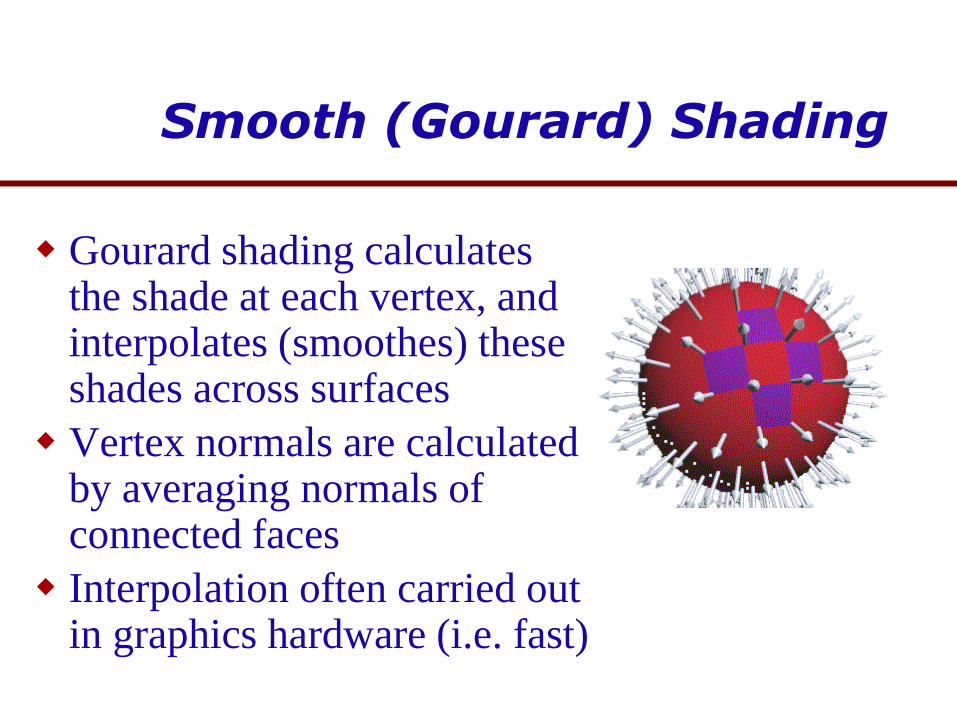
Smooth (Gourard) Shading
Gourard shading calculatesthe shade at each vertex, and interpolates (smoothes) these shades across surfaces
Vertex normals are calculated by averaging normals of connected faces
Interpolation often carried out in graphics hardware (i.e. fast)

Normal Interpolating (Phong) Shading
Phong shading calculates the normal at each vertex, and interpolates these normalsacross the surfaces
the light, and therefore shade, at each pixel is individually calculated from its unique surface normal

Lambert vs. Gourard Shading

Lighting in X3D
Three different types of lights are available:
Point lights - rays emanate in all directions from a 3D point source
Directional lights - rays emanate in one direction only from infinitely far away (like the sun)
Spot lights - project a cone of light from a 3D point source, targeted in a specified direction.
X3D lights also contribute to the overall “ambient” lighting by a specified amount.
Ambient lighting is a simulation/estimation of complex light/surface interaction
Attenuation defines how quickly a light's intensity fades, as you move away from the light source

X3D Light Nodes
< PointLight
on (TRUE or FALSE)
location (3D co-ordinate)
radius (radius of illumination sphere)
intensity (from 0.0 to 1.0)
ambientIntensity (from 0.0 to 1.0)
color (RGB value)
attenuation (3 values)
/>
< DirectionalLight
on
intensity
ambientIntensity
color
direction (3D point)
/>
< SpotLight
on
location
direction
radius
intensity
ambientIntensity
color
attenuation
beamWidth (radians)
cutOffAngle (radians)
/>
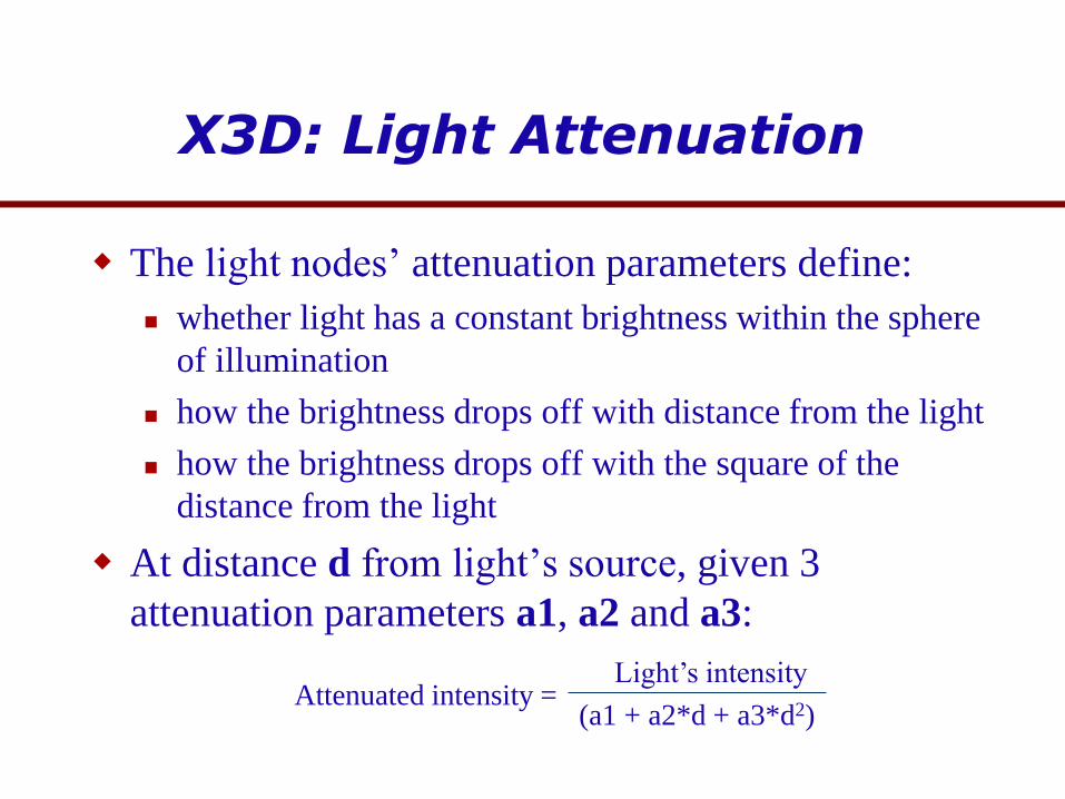
X3D: Light Attenuation
The light nodes’ attenuation parameters define:
whether light has a constant brightness within the sphere
of illumination
how the brightness drops off with distance from the light
how the brightness drops off with the square of the
distance from the light
At distance d from light’s source, given 3
attenuation parameters a1, a2 and a3:
(a1 + a2*d + a3*d2)
Light’s intensityAttenuated intensity =

DirectionalLight example
<Scene>
<Group>
<Transform DEF='UnlitShapeOne' translation='-3.0 0.0 0.0'>
<Shape>
<Box/>
<Appearance DEF='App'>
<Material diffuseColor='0.8 0.4 0.2'/>
</Appearance>
</Shape>
</Transform>
<Group DEF='LitParent'>
<Transform DEF='LitShapeOne' translation='0.0 2.0 0.0'>
<Shape>
<Sphere/>
<Appearance USE='App'/>
</Shape>
</Transform>
<DirectionalLight direction='1 1 1' />
<Transform DEF='LitShapeTwo' translation='0.0 -2.0 0.0'>
<Shape>
<Cylinder/>
<Appearance USE='App'/>
</Shape>
</Transform>
</Group>
<Transform DEF='UnlitShapeTwo' translation='3.0
0.0 0.0'>
<Shape>
<Cone/>
<Appearance USE='App'/>
</Shape>
</Transform>
</Group>
</Scene>
A DirectionalLight source illuminates only
the objects in its enclosing grouping node…
(note the use of the 'headlight' to see the other
shapes!)

PointLight example
A PointLight source potentially illuminates everything in the scene
Turn off the headlight to see what's happening..
animatedLights.x3d
Same geometry as previous example, with a PointLight
rather than DirectionalLight:
<PointLight DEF='TheLight' location='1 1 1'
radius='40' />
.. and with animation nodes at the end:
<TimeSensor DEF='Clock' cycleInterval='10'
loop='true'/>
<PositionInterpolator DEF='LightPath' key='0.0 0.25
0.5 0.75 1.0' keyValue='-5 5 0, -5 -5 0, 5 -5 0, 5 5
0, -5 5 0'/>
<ROUTE fromNode='Clock' fromField='fraction_changed'
toNode='LightPath' toField='set_fraction'/>
<ROUTE fromNode='LightPath' fromField='value_changed'
toNode='TheLight' toField='set_location'/>

X3D Materials
The Material node type is used as a child of an Appearance node
< Material
diffuseColor (RGB values)
specularColor (RGB values)
ambientIntensity (0.0 to 1.0)
emissiveColor (RGB values)
transparency (0.0 to 1.0)
shininess (0.0 to 1.0)
/>
X3D renderers uses a simplified
simulation of lighting and shiny
surfaces
Diffuse reflection is caused by
light scattering off a surface in all
directions - the result is a dull
effect with no sparkles or glints
Specular reflection is caused by
light bouncing off a shiny surface
in a predictable way.

Reflections
Perfect Specular
Reflection
Imperfect Specular
Reflection
Perfect Diffuse Reflection

Animating Colour and Transparency
The ColorInterpolator node is used to animate colour, and the
ScalarInterpolator node to animate transparency (and any other field
which has a single/scalar value).
When interpolating colour values between the supplied key values, the
ColorInterpolator uses the HSI colour scheme, since RGB would
create incorrect intermediate colours.
RGB interpolation
HSI interpolation

Example
<Scene DEF='scene'>
<Group>
<Shape>
<Appearance>
<Material DEF='BallColor' diffuseColor='1 0 0'/>
</Appearance>
<Sphere/>
</Shape>
<Shape>
<Appearance>
<Material diffuseColor='0.5 0.25 1'/>
</Appearance>
<Cylinder height='0.05' radius='2'/>
</Shape>
<Shape>
<Appearance>
<Material diffuseColor='0.75 0 1'/>
</Appearance>
<Cylinder height='5' radius='0.15'/>
</Shape>
<TimeSensor DEF='Clock' cycleInterval='4' loop='true'/>
<ColorInterpolator DEF='ColorPath' key='0 0.33 0.67 1' keyValue='1 0 0 0 1 0 0 0 1 1 0 0'/>
<ScalarInterpolator DEF='TransparencyPath' key='0 0.5 1' keyValue='0 1 0'/>
</Group>
<ROUTE fromNode='Clock' fromField='fraction_changed' toNode='TransparencyPath' toField='set_fraction'/>
<ROUTE fromNode='Clock' fromField='fraction_changed' toNode='ColorPath' toField='set_fraction'/>
<ROUTE fromNode='ColorPath' fromField='value_changed' toNode='BallColor' toField='set_diffuseColor'/>
<ROUTE fromNode='TransparencyPath' fromField='value_changed' toNode='BallColor' toField='set_transparency'/>
</Scene>
animatedColour.x3d

The Polygon ‘Mapping’ Techniques
Texture mapping
Mip mapping/ LODs
Light mapping
Environment mapping
Bump mapping
Specular mapping
Transparency mapping
etc.

Texture Mapping & Mip Mapping
Texture Mapping:
maps a raster image onto a surface
affects its shading (but it remains smooth)
may look unrealistic because direction of light illuminating texture map will be constant and not the same as that illuminating the surface
not good when viewed closely, because lighting will expose the true, flat nature of a surface
Mipmapping:
at least two (and probably four) textures of progressively lower resolution are used for a surface, and the graphics API uses the pixels from one of these depending on the distance and orientation of the surface as it is rendered

Precomputed shading for realtime applications
Computation begins at light sources
“Patches” of light are traced into the scene and their interactionswith surfaces are calculated and stored as ‘baked textures’
Diffuse reflected light from the surfaces is calculated also (=expensive, slow – but precomputed!)
Radiosity is viewpoint independent, therefore a lot of the work can be pre-calculated, i.e. calculated off-line prior to the real-time application rendering the model
Radiosity is a classic example of the type of pre-computation that is often performed in real-time 3D applications, and will work perfectly well assuming lights/surfaces aren’t moving
Typically applied just to fixed objects
Radiosity

Ambient Occlusion
http://www.independentdeveloper.com/archive/2007/11/27/what_is_ambient_occlusion
Excellent explanation here!
CT404/AmbientOcclusion.html
• Reduces ambient lighting
on parts of an object that
are heavily occluded by
nearby geometry
• Estimated through
sampled raycasts
• May be pre-calculated if
geometry + lights are
static (‘sky lights’)

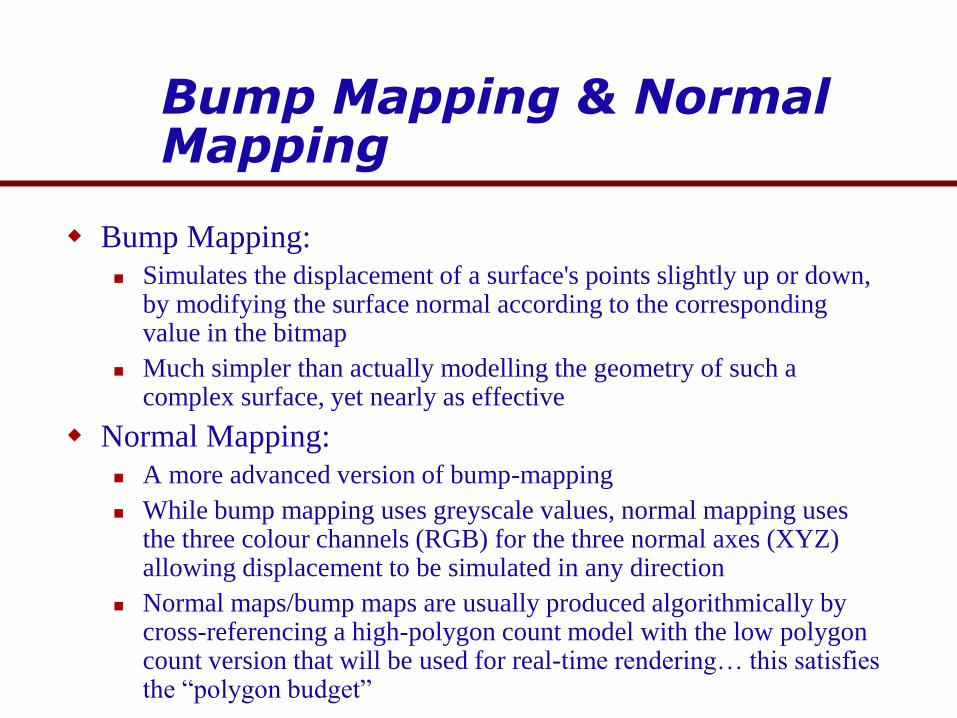
Bump Mapping & Normal Mapping
Bump Mapping:
Simulates the displacement of a surface's points slightly up or down, by modifying the surface normal according to the corresponding value in the bitmap
Much simpler than actually modelling the geometry of such a complex surface, yet nearly as effective
Normal Mapping:
A more advanced version of bump-mapping
While bump mapping uses greyscale values, normal mapping uses the three colour channels (RGB) for the three normal axes (XYZ) allowing displacement to be simulated in any direction
Normal maps/bump maps are usually produced algorithmically by cross-referencing a high-polygon count model with the low polygon count version that will be used for real-time rendering… this satisfies the “polygon budget”

Bump Mapping
Operates by modifying
surface normals (along
one axis) and therefore
shading
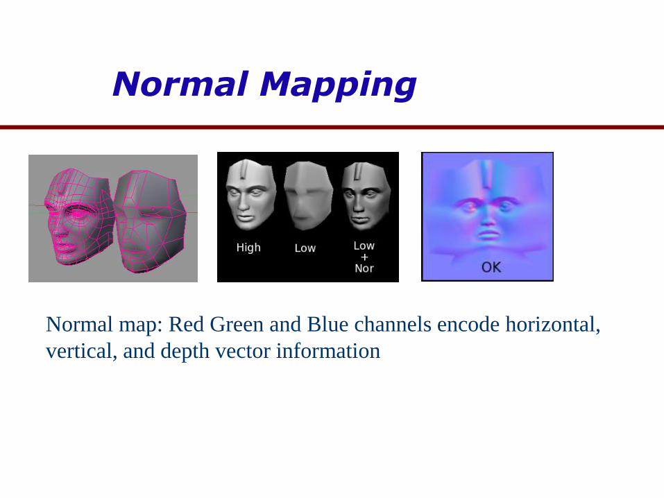
Normal Mapping
Normal map: Red Green and Blue channels encode horizontal,
vertical, and depth vector information

X3D Texture Mapping
Texture mapping allows you to 'paste' a bitmapped image or mpeg animation (.mpg) onto any X3Dshape except (for obvious reasons) PointSets and IndexedLineSets
Various nodes that go inside a shape's Appearancenode can be used:
ImageTexture - maps an image file (.jpg, .gif, .png)
PixelTexture - the individual pixel values are specified in the X3D code itself
MovieTexture - maps an mpeg movie file

X3D Texture Mapping
The default orientation of a texture
on a shape depends on the type of
shape
<ImageTexture
url = '' (URL of image file)
/>
<MovieTexture
url = '' (URL of mpeg file)
speed = '' (speed factor)
/>

Texture Mapping Example
<Scene DEF='scene'>
<Group>
<Shape>
<Appearance>
<Material/>
<ImageTexture url='cantop.jpg'/>
</Appearance>
<Cylinder bottom='false' side='false' height='2.7'/>
</Shape>
<Shape>
<Appearance>
<Material/>
<ImageTexture url='canbot.jpg'/>
</Appearance>
<Cylinder side='false' top='false' height='2.7'/>
</Shape>
<Shape>
<Appearance>
<Material/>
<ImageTexture url='canlabel.jpg'/>
</Appearance>
<Cylinder bottom='false' top='false' height='2.7'/>
</Shape>
</Group>
</Scene>

Texture Coordinates
Texture space is
normally represented by
(u,v) with each in the
range [0 ... 1]
u
v
0,0 1,0
0,1 1,1
0.65, 0.89
s
t
-1 0 1 2
2
1
0
-1
Surface space is normally represented
by (s, t) which measure repetitions of
(u,v)
one unit on the s or t axis represents
one complete repetition of the image
(allowing tiling)
The TextureCoordinate and TextureTransform Nodes
To map (s, t) coordinates to positions in the 3D world itself, X3D uses the TextureCoordinate node. This defines, for each vertex in a shape, the texture location (via (u, v) coordinates), size and repetition information (via (s, t) coordinates).
In practice, this gets too complex to calculate manually: TextureCoordinates are therefore normally produced as part of the export process from special-purpose 3D modelling software (e.g. 3Dstudio, Blender, Maya)
TextureTransform provides a more manageable way of manually defining texture sizes, repetitions and positions
Allows you to define (or even animate) rotation, translation and scaling transformations on the texture coordinates

Translating with TextureTransform
Texture translation movesa texture up, down, left, right on its surface.
Specified via two numbers which represent the (s, t) values – s controlling horizontal movement and t controlling vertical movement
Movement occurs in multiples of the s, t values – e.g. a translation of 0.5 0.5 moves a texture a distance equal to half of its width both horizontally and vertically
<Scene DEF='scene'>
<NavigationInfo type='EXAMINE'/>
<Viewpoint orientation='-0.639 -0.754 -0.153 0.617'
position='-1.995 1.668 4.105' fieldOfView='0.785'/>
<Group>
<Shape>
<Appearance>
<Material ambientIntensity='0.25'/>
<ImageTexture url='mandrill.jpg'/>
<TextureTransform translation='0.5 0.5'/>
</Appearance>
<Box/>
</Shape>
</Group>
</Scene>

Scaling with TextureTransform
Scaling shrinks/grows the texture from the surface’s origin.
Controlled using the scale field, which again consists of two numbers, defining scaling on the horizontal (s) and vertical (t) axes.
The numbers define how many times the texture is to be repeated: e.g. a scale of 2.0 2.0 shrinks the texture so that two copies are displayed in each direction
e.g:, use the same code as in the previous example, but replace the definition for the TextureTransformnode with:
<TextureTransform scale='2.0 2.0'/>
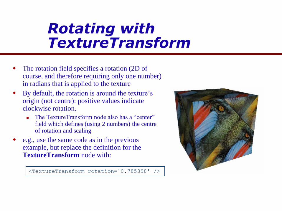
Rotating with TextureTransform
The rotation field specifies a rotation (2D of course, and therefore requiring only one number) in radians that is applied to the texture
By default, the rotation is around the texture’s origin (not centre): positive values indicate clockwise rotation.
The TextureTransform node also has a “center” field which defines (using 2 numbers) the centre of rotation and scaling
e.g., use the same code as in the previous example, but replace the definition for the TextureTransform node with:
<TextureTransform rotation='0.785398' />

Texture Image Sizes
Depending on the user’s X3D renderer, textures may be
limited to 128x128 pixels maximum, or perhaps 256x256...
1024x1024… or more?
Many 3D rendering engines (including those used by X3D
viewers) require textures that are of a “power of 2” size: 16,
32, 64, 128, etc..
Why? For mipmapping
Some also require that textures are square
The X3D viewer will probably adjust textures that don’t
meet its requirements, but this may lead to incorrect looking
images that are unnecessarily big for downloading

X3D: Backgrounds
X3D provides a Background node which defines the appearance of:
a large box that encompasses the whole world and which is always rendered at a fixed distance from the camera. Often referred to as the “skybox” or “worldbox”
a ground hemisphere, outside the box
a sky hemisphere, also outside the box
Used to efficiently define and render the sky, ground, and other items which always remain in the “far distance”
World Boxes are a standard polygon-saving trick..

Backgrounds: Sky and Ground Hemispheres
The colour gradients of the ground and sky hemispheres are defined via sets of
colours and the angles (starting at zero at the top of the hemisphere) at which each
stated colour appears.
The colours in between the explicitly stated colours are interpolated, producing
gradients
There is always one more Color than Angle since the first angle is assumed to be zero
E.g:
<Scene DEF='scene'>
<Background DEF='BlueSky' groundAngle='1.5' groundColor='0.05 0.1 0.05 0.25 0.6 0.25'
skyAngle='1.0472 2.09439' skyColor='0.1 0.1 0.3 0.2 0.2 0.6 0.6 0.6 0.99'/>
</Scene>

Backgrounds: the Skybox
The textures that are displayed on the 6 faces of the skybox
are defined in the Background node using the following
fields: backUrl, bottomUrl, frontUrl, leftUrl, rightUrl, topUrl
Since the skybox is closer to the camera than the sky and
ground hemispheres, they can be ignored completely, or can
use textures with transparency.

Billboards
Billboards are a standard trick used in realtime 3D
graphics applications, producing good results while
effectively managing the “polygon budget”
A billboard is a single polygon that is automatically
rotated to face the camera each time it is rendered.
Widely used for trimmings such as trees, clouds,
precipitation, etc.
'True' billboards versus 1-axis billboards..
Particle emitters (smoke, flame, snow)
Transparency (using .png textures) is often used. The
alpha transparency offered by .png is better than .gif, as it
doesn’t produce the harsh edges that simple transparency
does

Fog
Adds realism, and also efficiency through distance-based culling
(i.e. in combination with far-plane in viewing frustum)
In X3D syntax, visibilityRange defines the distance at which
objects become lost in the fog
fogType can have one of two values:
"LINEAR" - fog thickness increases linearly with distance from the
viewer
"EXPONENTIAL" - fog thickness increases exponentially
<Fog
color='0.5 0.5 0.5'
visibilityRange='500'
fogType='LINEAR'
/>

Shaders
Programs that are executed on the video hardware, detailing at a low level the procedure for manipulating the vertices or pixels on the screen
Vertex shaders:
manipulate vertex data values via mathematical operations on an object’s vertices
can affect various properties of a vertex (colour, lighting etc.) but most noticeably its orientation, position, and normal
allows dynamic (rather than pre-rendered) animation effects, e.g. clothing, hair, etc.
Pixel shaders:
operate at the level of the discretely viewable pixel
Applied later in the rendering pipeline, i.e. after 3D data has been transformed to 2D (pixel buffer) data
defining flexible and fast dynamic operations to apply to the colour at that point, allowing dynamic lighting and material effects (e.g. bloom, cel shading, depth blur, motion blur etc.)

Demo. Of Techniques
Many of the graphics techniques we have
been discussing are illustrated in the TGEA
demo (www.torquepowered.com,
www.garagegames.com)
CT404\TGEA_Demo\TGEDemoAdvanced.exe
Interactive walkthrough
Top Related