


Languages
Pages
Legal


Second-Harmonic Fundamental ModeSlotted Peniotron
Pulsed Power Plasma Science Conference, PPPS-2001
Las Vegas, Nevada June 7-22, 2001
This work has been supported by AFOSR under Grant F49620-99-1-0297 (MURI MVE).
Distribution Statement A: Approved for Public Release; Distribution is Unlimited
L.J. Dressman*, D.B. McDermott, and N.C. Luhmann, Jr.
University of California, Davis*Also NAVSEA, Crane
D.A. Gallagher
Northrop Grumman Corp.
T.A. SpencerAir Force Research Lab.
1 of 22 1a

Abstract
The harmonic peniotron has been demonstrated to be a highly efficient generator of millimeter-wave power [1]. Since a practical peniotron design must provide immunity to mode competition from gyrotron interactions as well as high device efficiency, the UC Davis peniotron design [2] employs an overcoupled interaction cavity for a predicted device efficiency of 47% at 34 GHz. Stability will be insured by operation in the lowest order mode of a slotted four-vane (magnetron type) circuit, the /2 mode. The TE11-like /2 mode couples well to the TE11 mode of the circular output waveguide through the 2.5 mm radius iris at the end of the cavity. The output diffraction coupling configuration results in heavy loading of higher order axial modes and avoids mode conversion in the output waveguide. For diagnostic purposes, the experimental device will also incorporate side-wall coupling to the cavity. The peniotron will operate with a 70 kV, 3.5 A, =1.5, axis-encircling electron beam generated by a recently developed Northrop Grumman Cusp gun [3]. Large-signal simulation of the interaction predicts an electronic efficiency of 58% and an extracted power output of 120 kW (47% device efficiency). The overall efficiency can be raised to 57% by use of a depressed collector.
[1] T. Ishihara, et al., IEEE Trans. on Electron Devices 46, 798 (1999).[2] D. B. McDermott, et al., IEEE Trans. on Plasma Science 28, 953 (2000).[3] D. Gallagher, et al., IEEE Trans. on Plasma Science 28, 695 (2000).
1b2 of 22

Second-Harmonic Fundamental Mode Slotted Peniotron
Objectives
Approach Accomplishments• Received two Northrop Cusp guns
• 34 GHz 2nd-harmonic peniotron design - 125 kW with 47% device efficiency - Employs Northrop Cusp gun
• 34 GHz slotted cavity and coupler was designed with HFSS for high efficiency
• Axis-encircling electrons generate mth-order azimuthal mode in sth-harmonic peniotron if m=s+1
• Slotted circuit enhances interaction and allows stable, lowest-order mode to have desired mth-order symmetry
• Cusp gun produces needed axis-encircling electron beam
• Improve device efficiency of Tohoku’s recent third-harmonic =35% peniotron
• Achieve device efficiency of 50% in harmonic gyro-device
• Foundation for peniotron-amplifiers
TE11-Like Mode in Slotted Cavity
3 of 22 1c

4 of 22
Description of Peniotron
– Fast-Wave Device– Similar to Gyrotron– Driven by Electrons’ Transverse Velocity – Optimized for Axis-Encircling Electron Beam– Resonance Condition with TEm1 Wave:
= sc + kzvz
s Cyclotron Harmonics = m for Gyrotron (Synchronism)
s = m-1 for Peniotron (Asynchronism)
2a

5 of 22
Motivation for Peniotron
• Proven High Efficiency– 75% Electronic Efficiency
• Predicted Higher Efficiency– Efficiency >80% is Predicted
• Gyrotron Replacement– Higher Efficiency than Gyrotron
– High Frequency Source well suited for Cyclotron Harmonic Emission
2b

State of the Art
• Tohoku University Team Recently Demonstrated Extremely High Efficiency– [ T. Ishihara, et al., IEEE-ED 46, p. 798, 1999 ]
– 30 GHz, 3rd-Harmonic Peniotron
– Slotted (Magnetron Type) Waveguide, 2 Mode
– Significant Achievement: Electronic Efficiency of 75%
– 35% Device Efficiency due to Critically Coupled Cavity
6 of 22 2c

• Peniotron Resonance with TEm1 Wave:
= (m-1)c + kzvz
• Electrons Move Forward by 360o each Orbit
• Wave Appears as “DC” Electric Field
• Electrons E x B Drift to Deceleration Phase
Peniotron Interaction
7 of 22 3a

E-Field
Slotted Circuit
TE11-Like Modewith TE31 Content
UCD Peniotron Features
• Second-Harmonic Operation - 34 GHz
• Operation in /2 Cavity Mode– 4-Vane Slotted Waveguide– Lowest Order Mode– Contains Needed m=3 Component– Suppresses Gyrotron Modes– Easily Couples to Circular Output
Waveguide
• New Northrop Grumman Cusp Gun– High Quality Axis-Encircling Beam– High Efficiency Interaction– High Power (125 kW)
8 of 22 3b

Mode Selection for Axis-Encircling Electrons:
s = Cyclotron Harmonic
m = s for Gyrotron
m = s+1 for Peniotron
4-Vane Slotted Circuit Yieldsm=3 for Lowest Order Mode
Dispersion Diagram/Mode Selection
Lowest Order Mode Ensures Stability
9 of 22
-2 -1 0 1 20
1
2
3
Peniotron
r w
/c
2 (m=0,4) (m=1,3) (m=2)
Strongest Competing Modeis 4th-Harmonic Gyrotron
kzrw
4a

Nearest Competing Mode: 4th-Harmonic Gyrotron
Start oscillation current for competing 4th-Harmonic Gyrotron is four times higher than Peniotron start current.
Excellent Stability Predicted
Magnetic Tuning Curve
10 of 22
B0 (kG)5.5 6.0 6.5 7.0 7.5
I s (A
)
0
1
2
3
4
5
6
PeniotronGyrotron
OperatingCurrent
Gyrotron Starting Currentis Above Peniotron’s
4b

Ib (A)0 1 2 3 4 5
Eff
icie
ncy
(%
)
0
20
40
60
80
100
Po
ut (kW
)
0
50
100
150
200
Pout
50% Efficiency Predicted
Efficiency Predictions:
Electron Efficiency 58%
Device Efficiency 47%
Device Efficiency withDepressed Collector 57%
Collector Potential 12.8 kV
Power and Efficiency
Peniotron has been Simulated with Nonlinear Code
11 of 22
dev
dep
elec
4c

Beam Voltage 70 kVBeam Current 3.5 AVelocity Ratio, v/vz 1.5Magnetic Field 6.5 kGVelocity Spread, vz/vz 5%Guiding Center Spread, rc/rL 10%Mode /2Axial Mode Number 1Vane Depth, b/a 1.45Electron-Vane Ratio, rL/a 0.65Inner Vane Radius, a 1.82 mmCavity Length 31 mmSlot Angle, o 22.5Unloaded Q, Q0 1900Loaded Q, QL 357
Design Parameters
12 of 22
2
r b
a
L
5a

SlottedCavity
Cutoff Drift Tube
Circular Iris (Removable)
Cavity Design
13 of 22
Output CircularWaveguide r=4.5 mm
Iris Radius for Critical Coupling: 2.35mm, QL=990
Iris Radius for Over Coupling: 2.55mm, QL=357
Q0=1900
Diagnostic CouplingPorts
5b

Frequency (GHz)33 34 35 36 37 38 39 40
S11
(d
B)
-5
-4
-3
-2
-1
0
Operating Mode, QL=357
2nd Axial Mode, QL=102
3rd Axial Mode, QL=59
Couples to TE11 Circular
Waveguide Mode
Diffraction Coupling– Overcoupled for High Device Efficiency - 47% Predicted
– Efficiency Increased by Depressed Collector - 57% Expected
– Suppresses Higher Order Axial Modes
Cavity Design–Diffraction Coupling
14 of 22
1st Axial Mode,34 GHz
5c

Frequency (GHz)33 34 35 36 37 38 39 40
S21
(d
B)
-60
-50
-40
-30
Coupling to Operating Mode
Coupling to 2nd Axial Mode
Diagnostic Coupling– Couples to standard WR-28 rectangular waveguide
– Coupling to adjacent slots will load both components of circularly polarized wave
Diagnostic Sidewall Couplers
15 of 22
Diagnostic CouplingCouples toTE10 Mode
E E
E
6a

Frequency (GHz)34 36 38 40 42 44
S21
0.0
0.1
0.2
0.3
0.4
0.5
TE11 Output
TM11 Output
Conversion to TM11 Mode
Only Above 40.0 GHz
Mode Conversion Occurs Only at Higher Frequencies - TM11 Mode is Excited
Output Mode Conversion
16 of 22 6b

UCD Peniotron will use state-of-the-art Cusp gun developed by Northrop Grumman
Cusp Gun
17 of 22 7a

Axis Encircling Beam Parameters:Beam Voltage 70 kVBeam Current 3.5 AVelocity Ratio, v/vz 1.5Velocity Spread, vz/vz 5%Guiding Center Spread, rc/rL 10%
Cusp Gun
18 of 22 7b
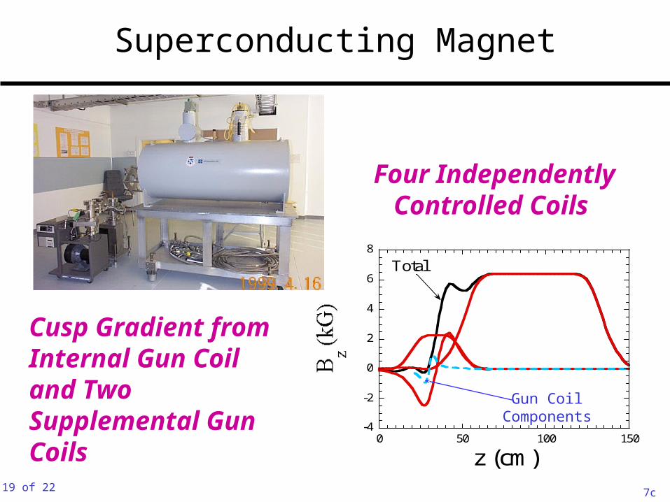
Four IndependentlyControlled Coils
Superconducting Magnet
19 of 22
-4
-2
0
2
4
6
8
0 50 100 150
z (cm)
Total
Gun CoilComponents
Cusp Gradient from Internal Gun Coil and Two Supplemental Gun Coils
7c

50% Device Efficiency Predicted
Summary
• Peniotron Demonstrated Very High Efficiency (Tohoku)
• UCD Peniotron Designed For High Device Efficiency
/2 Slotted Circuit Mode Provides Stability and m=3 Component for s=2 Peniotron
• Overcoupled Cavity Provides High Device Efficiency
• Northrop Grumman Cusp Gun Provides Required Axis-Encircling Beam
20 of 22 8a

Future Work
• Circuit Fabrication
• Cold Test
• Electron Beam Test
• Hot Test the Peniotron
21 of 22 8b

Sign Up Sheet
22 of 22 8c
Top Related