


Languages
Pages
Legal


R.007, March 2012 SCT TAN s.l.
SSCCTT
SMALL CRAFT. - SCANTLINGS
International ISO Standard 12215-5
CHAPTER Pag.
Introduction 1
Scantlings 3
Data Introduction 4
Getting Help 5
Defining the Structure 6
Work procedure 9
Materials Definition 11
Outputs in MS Word 12
1

R.007, March 2012 SCT TAN s.l.
INTRODUCTION
SCT is an application that tries to help the designer in the scantling of small crafts, according the ISO Standard 12215-5, inside the scope defined by it self
The initial window of the application looks as follow :
It is a window of the called type “MDI”, which acts as a container for several other windows, called secondary windows, than the User can open along the same working session.
This window has its owns heading menus , as we will se later, but, when one of the secondary windows becomes the “active window”, the main window will only show the secondary window menus.
For this reason, in order to access to the MDI window’s menus, any secondary windows must be unloaded.
1

R.007, March 2012 SCT TAN s.l.
HEADER’S MENUS
New Study: opens a secondary Windows to get the directory, identification and any other data for the new study.
Open Existing Projects : opens a dialog box with the Windows Explorer directory tree, to allow the designer to look for any existing project, and load its data.
Last projects : shows up to the 5 last projects we have been dealing with. By clicking on its name, the application will load its data and the window “Scantlings” will be open.
Delete History : deletes the list (not the projects) with the last used projects.
Exit . Closes the application
Language : allows the User to select the language to be used by the application.
Always start with Scantlings : when this option is ticked, the window “Scantlings” will automatically be shown when starting any new work session.
Change Window Picture : allows to select a new image for the Background of the MDI window.
Delete Window Picture : no image will appear
REMARK : Options selected with the menu “Preferences” are saved by the application, that will remember them while not further changes.
Scantlings : Opens the window to work with scantlings properly.
Materials : Open the window to work, modify or add, materials.
Calculation of Beams : opens the modulus to calculate frames and continuous beams.
ISO 12215-8 : rudders calculation (not yet available at this time)
Help : Opens the User’s Manual in pdf format
REMARK : The window “Scantlings” has its own menu “Preferences”, that IS DIFFERENT THAN the one we have just described, allowing the User to select specific preferences for working in scantlings.
.
2

R.007, March 2012 SCT TAN s.l.
SCANTLINGS
The window to work with scantlings looks like in the image, with two differentiate areas :
The left one shows all the elements forming the structure of the ship.
The right hand area relates the properties of any of the precedent elements, as well as the results when applying them the ISO Standard 12215-5.
Clicking with the left button of the mouse over any one of the nodes in the left tree, the table in the right side will show its properties.
Selecting any element in the window with the mouse left button and, then, clicking on the right button, several pop-up menus will appear, helping the User in some tasks as :
Giving new data
Modifying existing data
Adding elements
Explanations about required data : menu “What is this?” (see image)
Etc.
The total amount of nodes, elements, in the left hand tree is unlimited. However, as every node needs to be linked to a table with its properties, the memory used can be very high and calculations speed may be affected. Within a complex project the number of nodes can become very high. That’s why, in order to avoid confusion, the selected node will appear with the mark so that we can know that the properties in the right hand table are its properties. On the other hand, if no node is marked with that icon, and we ask the application to do any calculation, we could get improper or not coherent results.
3
R.007, March 2012 SCT TAN s.l.
DATA INTRODUCTION
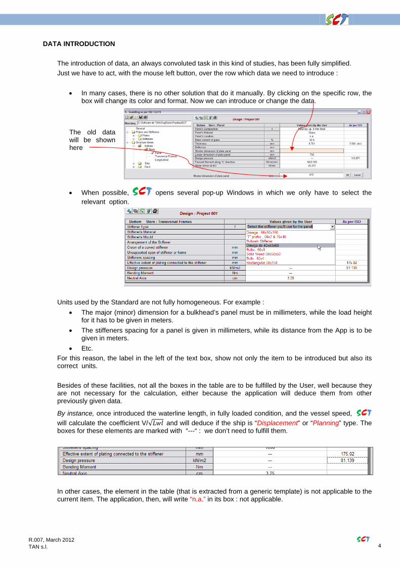
The introduction of data, an always convoluted task in this kind of studies, has been fully simplified.
Just we have to act, with the mouse left button, over the row which data we need to introduce :
In many cases, there is no other solution that do it manually. By clicking on the specific row, the box will change its color and format. Now we can introduce or change the data.
The old data will be shown here
When possible, SCT opens several pop-up Windows in which we only have to select the relevant option.
Units used by the Standard are not fully homogeneous. For example :
The major (minor) dimension for a bulkhead’s panel must be in millimeters, while the load height for it has to be given in meters.
The stiffeners spacing for a panel is given in millimeters, while its distance from the App is to be given in meters.
Etc.
For this reason, the label in the left of the text box, show not only the item to be introduced but also its correct units.
Besides of these facilities, not all the boxes in the table are to be fulfilled by the User, well because they are not necessary for the calculation, either because the application will deduce them from other previously given data.
By instance, once introduced the waterline length, in fully loaded condition, and the vessel speed, SCT
will calculate the coefficient V/√ and will deduce if the ship is “Displacement” or “Planning” type. The boxes for these elements are marked with “---“ : we don’t need to fulfill them.
In other cases, the element in the table (that is extracted from a generic template) is not applicable to the current item. The application, then, will write “n.a.” in its box : not applicable.
4

R.007, March 2012 SCT TAN s.l.
GETTING HELP
There are two ways to get help :
1. At the top left of the window, among several other menus, is the one called Help.
By clicking on it, a secondary window will appear with a list with the different available help topics.
Pressing in the left area, over the required item, the right hand area will show appropriate explanations. They are, usually, existing figures in the ISO Standard 12215-5.
2. Pressing in the main window over a node, label or box, first with the mouse left button and, then, with the right hand button, the What is This? pop-up menu will appear.
Pressing now on it, appropriate explanations will be shown to the User. Sometimes the application will indicate that does not exist such explanation, well because it is obvious or because we just have to choose among the possibilities listed in a pop-up window, making unnecessary more details.
5
R.007, March 2012 SCT TAN s.l.
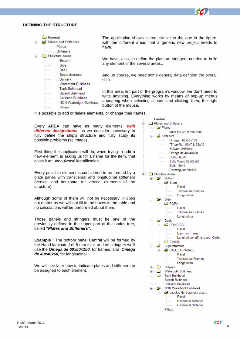
DEFINING THE STRUCTURE
The application shows a tree, similar to the one in the figure, with the different areas that a generic new project needs to have.
We have, also, to define the plats an stringers needed to build any element of the several areas..
And, of course, we need some general data defining the overall ship.
In this area, left part of the program’s window, we don’t need to write anything. Everything works by means of pop-up menus appearing when selecting a node and clicking, then, the right button of the mouse.
It is possible to add or delete elements, or change their names.
Every AREA can have as many elements, with different designations, as we consider necessary to fully define the ship’s structure and fully study its possible problems (se image) .
First thing the application will do, when trying to add a new element, is asking us for a name for the ítem, that gives it an unequivocal identification.
Every possible element is considered to be formed by a plate panel, with transversal and longitudinal stiffeners (vertical and horizontal for vertical elements of the structure).
Although some of them will not be necessary, it does not matter as we will not fill in the boxes in the table and no calculations will be performed about them.
Those panels and stringers must be one of the previously defined in the upper part of the nodes tree, called “Plates and Stiffeners”.
Example : The bottom panel Central will be formed by the Hand laminated of 8 mm thick and as stringers we’ll use the Omega de 60x50x150, for frames, and Omega de 40x40x60, for longitudinal.
We will see later how to indicate plates and stiffeners to be assigned to each element.
6

R.007, March 2012 SCT TAN s.l.
In turn, when defining plates and stiffeners, we will have to specify the material they are made with, as well as the thickness, in case of plates. With stiffeners we have to indicate the profile type : flat bar, bulb bar, composed “T”, omega profile, etc. and to give the dimensions. All this will be carried out by introducing data in the boxes of the table that the application prepares for every element (pop-up Windows and text boxes) as mentioned before. Each table is activated by clicking on the correspondent node’s name in the left hand tree. . When working with a plate, the following window will be shown :
Initially boxes with white back color do not contains any data and they have to be filled in as previously indicated, acting over the boxes in grey back color, mouse left button and/or right button.
We have to give the thickness but, when it comes that the plate’s material is Glass, Carbon or Aramid, the application will include several additional rows, to receive data about mats, rovs, etc., that form every ply. In order to add a laminate :
1. Pick the corresponding row with the left mouse button..
2. Act over the right mouse button : a pop-up menu will appear and we will select the option “Add laminate”.
3. Over the selected row will appear a pop-up list with the diverse available elements.
4. Selecting one of and it will be incorporated in the selected row box.
And so on till complete all the plies needed for the laminate.
There exists the option of Copy a Previous Combination combination in a previous panel .
When choosing this option, a pop-up Windows appears with the list of existing panels.
Selecting one of them, its mats-rovs will be copied in the actual table, starting with the row we have picked-up first (see point 1)
7

R.007, March 2012 SCT TAN s.l.
Once this has be done, the button will calculate the physical properties of the current plate and the application will write them in the boxes of the table, without any additional action from our side . These properties will be taken into account at the moment of analyze the panels forming the structure.
Working with a stiffener the procedure is fully similar but we need to give also, its dimensions and, when dealing with glass, carbon or aramid, the composition for the laminate. There is a special option to put mat, rovs, only on the crown head. At this purpose the pop-up window undergoes a small change (see picture)
VERY IMPORTANT NOTE
In the case of fibres , we have to fill the appropriate box :
Evaluation Level of mechanical properties
A dropdown list appears with three options :
EL-a : The physical properties of materials that we use for the various layers must have been derived by standard tests in the laboratory. These values have been indicated previously by the user in the window “Materials” of the application
.The application will use the values entered by the user to calculate the stresses in each layer
.
EL-b : The physical properties are calculated according to the default values in tables C.4 to C.7, all based on the amount of fiber mass and the component of the layer.
EL-c : The physical properties are calculated as for EL-b but the values deduced from the tables C.4 to C.7 will be multiplied by a factor of 0,8
Should be consulted and proper understanding of the Annex C of the standard ISO 12215-5, paragraphs 1.2, 1.3, 1.4 and 1.5, before choosing the method used for the project under study
In most instances, it will be in the builders’ interest to adopt level “a” or combination of levels “a” and “b”. Use of level “c” carries a considerable penalty since neither the actual fibre content by mass, nor the quality of fabrication can be quantified with any certainty.
8

R.007, March 2012 SCT TAN s.l.
WORKING PROCEDURE
As it can be deduct from the precedent, the normal working procedure would be as follow :
1. DEFINITION
Introduction of the general data for the ship
Definition of the materials we need to use in this project : mats, rovs, types of steel or/and aluminum, woods, etc
Define plates and stiffeners to be used at every zone.
Specify the zones we need to divide the structure, which plate to use for every panel and type of stiffener for frames and longitudinals bordering the panel.
2.- CALCULATION
Once all dimensions have been defined as well as the position of every element in the structure, the application will deduce the real properties for everyone, and comparing them with the ISO Standard 12215.-5 requirements.
These requirements will appear on the fourth column of the table, marking with red color those properties below the requirements.
3.- CHECK
Looking at the results we can decide the convenience or not of modifying elements properties, spacing of stiffeners, the plate assigned to each panel, etc
4.- ANALYSIS PLY BY PLY
After properly tuned the structure, it is possible, if desired (sometimes it is compulsory) to carry out an analysis ply by ply. This analysis will provide the degree of acceptance of each layer and, as a result, the possibility of decreasing thicknesses without exceeding allowed design stresses and moments.
The application carries out this task with no more than to act on the toolbar’s button indicated in annexed figure. All the necessary data are present in the different tables of the
various elements and available to SCT.
On a template, specially prepared for this purpose in MS Excel, and fully similar to the one showed in the ISO Standard 12215-5 , will be arranged the results of the analysis.
Any amount of analysis can be performed and all of them will be added into a single Excel file.
5.- SAVE THE STUDY
The toolbar in the figure allows the User to save data and results.
It is very convenient to save them with some frequency in order to don not loose any one of them.
6.- OUTPUTS
9

R.007, March 2012 SCT TAN s.l.
The button in the toolbar of the Scantling window creates a document in MS Word with the data introduced for the study, the table properties for each element as well as the results for them.
Writing in Word is a slow procedure and, given that the structure may have a lot of components, it may last several minutes.
In the calculations of each panel or reinforcement are used several pressures and coefficients that can be displayed in a separate subwindow, if we click on the figure.The list of results in MS Word also displays these values
ANALYSIS PLY BY PLY
The ply analysis for each panel or stiffener are shown directly in an Excel Work Sheet specifically prepared for this study.
You can access the existing studies using the button in Figure
10

R.007, March 2012 SCT TAN s.l.
DEFINITION OF MATERIALS
This issue deserves a separate chapter and, in fact, the application has a separate window to deal with them, window that can be accessed through the header menu “Materials”.
On the window’s left part, a nodes tree shows all the materials we have at our disposal. The table on the right part shows the physical or mechanical properties for the specific material we selected on the tree.
SCT incorporates a collection of materials that, probably, will be enough for the 90% of the options we will ever shuffle in this issue. Although it is possible to modify the lists and the properties of every item, it would be preferable to consult to any distributor of the application to add or modify materials. When adding a new material, it is necessary to introduce all its mechanical properties. In the case of laminates, however, you only need to indicate the fiber content in %. The application, according with the formulas in the ISO Standard 12215- 5, will calculate them.
When defining any plate, one of the text boxes in the properties Table will ask us for the Plate’s Material. Picking over this box a pop-up window will appear, with the list of all available materials.
Quite similar procedure for stiffeners.
11

FINAL LIST SAMPLE IN MS WORD (single sheets from a list)
Project 001 03/03/2012 CONTENTS
GENERAL 4
PLATES 5
hand lay up, 8.7 mm thick 5
plate 5.2 mm thick 6
Sandwich 30 mm 7
plywood 24 mm 8
STIFFENERS 9
Glass Rectangular 50x150 9
Omega profile 60x50x140 10
T profile, 70x7 45x10 11
Bulwark Stiffener 40x30x40 12
Solid Wood 50x50x50 13
Omega 40x40x60 14
Bulb Bar 60x6 15
Omega 40x30x40 16
Flat Bar 200x14 17
BOTTON 18
Stern panelbotton 18
Stern frmbotton 19
Stern longbotton 20
SIDE 21
Stern panelside 21
Stern frmside 22
Stern longside 23
DECKS 24
Main Deck paneldeck 24
Main Deck frmdeck 25
Main Deck longdeck 26
Fore Castle Deck paneldeck 27
Fore Castle Deck frmdeck 28
Fore Castle Deck longdeck 29
BULWARK 30
Stern panelbulwark 30
Stern frmbulwark 31
SUPERSTRUCTURE 32
Passage House panelsuperstructure 32
Passage House frmsuperstructure 33
Passage House longsuperstructure 34
Deck House Front panelsuperstructure 35
Deck House Front frmsuperstructure 36
Deck House Front longsuperstructure 37
12

IMPORTANT NOTE
Weights indicated for laminates in tables below are dry fibre weights.
It is necessary to have practical data about how much weights, per sqm, a laminate with an X% of fibre.
On average, it can be said that for a laminate with a 40% in mass of fibre they are necessary about 650
gr/m2 of fibre,for every mm in laminate thickness, when using a “mat”, and about 1000 gr/m2 when
using “roving".
GENERAL
Builder
Building N.
Type of Hull Mono Hull
Design category A "ocean"
Power or Sail Motor
Length of the Hull m 24
Length of the fully loaded waterline at mLDC m 23.56
Beam of the hull m 5.8
Beam of the fully loaded waterline at mLDC m 5.75
Chine beam m 5.5
Depth m 2.6
Draugth at mLDC (TC) m 1.95
Maximum speed at mLDC knots 16
v/SQR(Lwl) Coefficient 3.296
Operating mode Displacement
Loaded displacement mass of the craft kg 68500
Deadrise angle at 0,4 LWL forward of its aft end º 25
Water specific gravity kg/m3 1025
13

PLATES
hand lay up, 8.7 mm thick
Plate's material Glass
laminated kind of ply Mat (WR), Manual lay-up
moulding Type Open mould simple surface
Evaluation Level (EL) of mechanical properties EL-b
mass content of fibre % 40.7
Total Thickness mm 9.217
Total Weight kg/m2 5.75
MATS & ROVINGS
MAT 450
ROV 800
800RV-450M
1700RV-300M
ROV 800
MAT 450
14
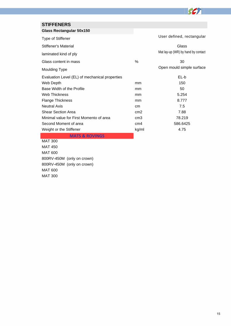
STIFFENERS Glass Rectangular 50x150
Type of Stiffener User defined, rectangular
Stiffener's Material Glass
laminated kind of ply Mat lay-up (WR) by hand by contact
Glass content in mass % 30
Moulding Type Open mould simple surface
Evaluation Level (EL) of mechanical properties EL-b
Web Depth mm 150
Base Width of the Profile mm 50
Web Thickness mm 5.254
Flange Thickness mm 8.777
Neutral Axis cm 7.5
Shear Section Area cm2 7.88
Minimal value for First Momento of area cm3 78.219
Second Moment of area cm4 586.6425
Weight or the Stiffener kg/ml 4.75
MATS & ROVINGS
MAT 300
MAT 450
MAT 600
800RV-450M (only on crown)
800RV-450M (only on crown)
MAT 600
MAT 300
15

BOTTON Stern : panelbotton Units Values given by the User As per ISO 12215-5
Panel's Composition hand lay up, 8.7 mm thick
Panel's Material Glass
Mass content of glass % 40.7
Thickness mm 9.217 7.894 (formula 35)
Deflection mm
Shorter dimension of plate panel mm 410
Longer dimension of plate panel mm 705
Design pressure kN/m2 --- 70.378
Flexural Moment along "b" direction N/mm/mm 948.377
Shear stress at b/2 N/mm 12.869
Distance of mid panel from of aft end of LWL m 3.2
Minimun dry fibre mass por the lay-up kg/m2 3.963 3.39
Panel's weight kg/m2 5.75
COEFFICIENTS AND PRESSURES USED IN THE CALCULATIONS
kDC = 1
nCG = 3
kAR = 1
kL = 0.614
PBMD base = 114.621
PBM MIN = 38.946
PBMD = 70.378
k2 = 0.481
k3 = 0.026
kC = 1
kSHC = 0.446
16

SIDE Stern : frmside Units Values given by the User As per ISO 12215-5
Stiffener Type Omega 40x40x60
Stiffener's Material Glass
Stiffener's Mould Open mould simple surface
Glass content in mass % 30
Arrangement of the Stiffener attached to hull or panel
Crown of a curved stiffener mm
Unsupported span of stiffener or frame mm 1000
Stiffeners spacing mm 750
Effective extent of plating connected to the stiffener mm --- 215.02
Design pressure kN/m2 --- 38.817
Bending Moment Nm ---
Neutral Axis cm 1.47
Shear area, Stiffener + Attached Plate cm2 24.28 7.043
First moment of area (Wx) cm3 123.592 57.082
Second moment of area (Ix) cm4 181.5218 23.6541
Stiffener's weight + attached `plate kg/ml 12.769
Height of stiffener's midpoint above WL m 1
Distance of mid stiffener from of aft end of LWL m 2
COEFFICIENTS AND PRESSURES USED IN THE CALCULATIONS
kDC = 1
nCG = 3
kAR = 0.593
kL = 0.572
kZ = 0.998
PDM base = 22.846
PSM MIN = 21.204
PSMP =0 .0155
kCS = 1
kSA = 7.5
17
Top Related