


Languages
Pages
Legal

sCO2 Turbomachinery and Low-Leakage sCO2 End Seals
GE Global Research Rahul Bidkar Doug Hofer Chiranjeev Kalra Andrew Mann Max Peter Rajkeshar Singh Edip Sevincer Azam Thatte Jifeng Wang
Southwest Research Institute Tim Allison Klaus Brun Stefan Cich Meera Day Chris Kulhanek Jeff Moore Grant Musgrove Aaron Rimpel
Disclaimer: "This report was prepared as an account of work sponsored by an agency of the United States Government. Neither the United
States Government nor any agency thereof, nor any of their employees, makes any warranty, express or implied, or assumes any legal
liability or responsibility for the accuracy, completeness, or usefulness of any information, apparatus, product, or process disclosed, or
represents that its use would not infringe privately owned rights. Reference herein to any specific commercial product, process, or service
by trade name, trademark, manufacturer, or otherwise does not necessarily constitute or imply its endorsement, recommendation, or
favoring by the United States Government or any agency thereof. The views and opinions of authors expressed herein do not necessarily
state or reflect those of the United States Government or any agency thereof."
Acknowledgement: "This material is based upon work supported by the Department of Energy under Award Number DE-FE0024007"

2 / GE sCO2 Turbines & Seals – UTSR
Nov 2015
Outline
• Overview – sCO2 power cycles
• sCO2 turbomachinery at GE
• 10 MWe turbine
• 450 MWe turbine
• End seals for sCO2 turbines
• sCO2 Seals test rig
3 / GE sCO2 Turbines & Seals – UTSR
Nov 2015
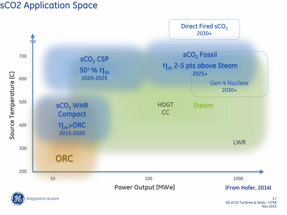
sCO2 Application Space
700
600
500
400
300
200
Steam
10 100 1000
Power Output [MWe]
So
urc
e T
em
pe
ratu
re [
C]
sCO2 CSP
50+ % th 2020-2025
ORC
LWR
HDGT CC
Direct Fired sCO2
2030+
Gen 4 Nuclear
2030+
sCO2 WHR Compact
th>ORC 2015-2020
sCO2 Fossil
th 2-5 pts above Steam
2025+
(From Hofer, 2014)

4 / GE sCO2 Turbines & Seals – UTSR
Nov 2015
Recompression sCO2 Cycle
• Recompression sCO2 cycle for CSP and utility-scale applications
• Recompression loop added for better recuperation
• Ongoing research in developing power plant components (turbines, compressors, recuperators)
• This presentation focuses on turbine maturation and turbine end seals for enabling higher cycle efficiencies
HEA
T
SOU
RC
E
T
HIGH TEMP RECUPTR
LOW TEMP RECUPTR
RECOMP COMP
COOLER
1
2
3
4
5
6
7
8 8
GEN
1
2
3
4
5
6
7
8
Te
mp
era
ture
Entropy
Typical sCO2 recompression cycle
T-S diagram
(From Kalra et al., 2014)

5 / GE sCO2 Turbines & Seals – UTSR
Nov 2015
sCO2 power cycle roadmap & technology gaps
Parallel development on components (Seals, bearings, valves) and materials to enable higher efficiencies
1
10
100
1000
No
min
al S
ize
(MW
)
2010 2015 2020 2025 2030
Sunshot SwRI-GE 10 MW Demo
(axial turbine)
CSP Application
(Hofer, 2014)
Echogen
Waste-Heat Recovery
Kacludis et al. 2012)
Medium scale Demo
(axial turbine)
(Nominal 50MW)
(Hofer. 2014)
Utility scale Demo
(axial turbine)
(Nominal 500MW)
RCBC Sandia
National Lab
(Wright et. al,
2011) IST, Bechtel Marine Prop.
Corp. (Clementoni et al.
2014)
Timeline for sCO2 turbomachinery development
Published work Projected Date
Technology gaps
(From Hofer, 2014)

6 / GE sCO2 Turbines & Seals – UTSR
Nov 2015
10 MWe SunShot turbine
Not to scale
• Very high power density turbine for CSP applications
• Key features
• Supercritical CO2 aero design
• Seals with thermal management
• Bearings and rotordynamics
10 MWe turbine
test stand
Thermodynamic cycle
10 MWe turbine rotor

7 / GE sCO2 Turbines & Seals – UTSR
Nov 2015
Test Loop –10 MWe turbine
SwRI B278
Heater
sCO2 Pump
Compressor
Cooler
GE partnering with Southwest Research Institute in demonstrating the turbine
Thermodynamic cycle Representation of Southwest
Research Test Loop
Picture of Southwest Research Test Loop
8 / GE sCO2 Turbines & Seals – UTSR
Nov 2015
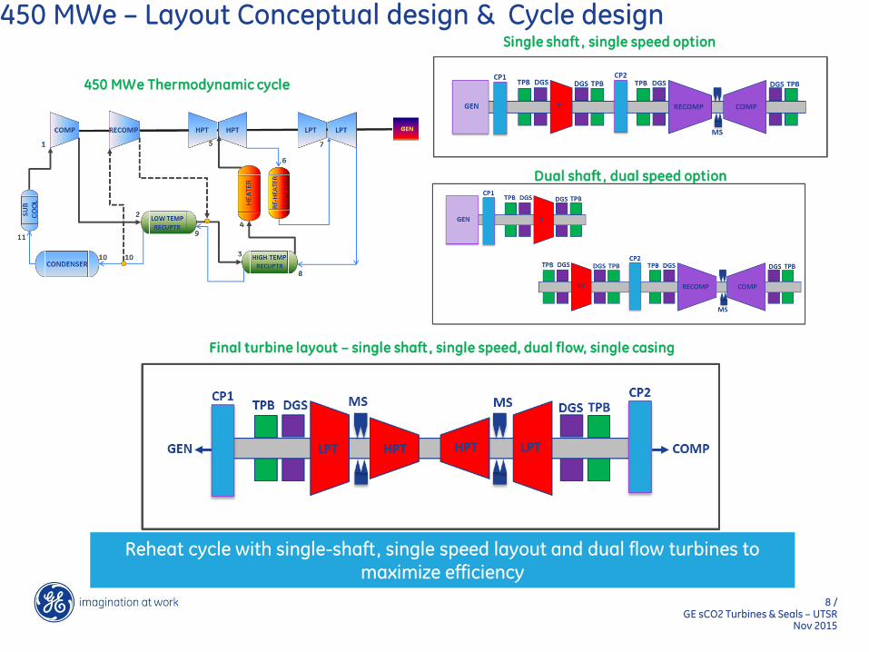
450 MWe – Layout Conceptual design & Cycle design
450 MWe Thermodynamic cycle
Single shaft , single speed option
Dual shaft , dual speed option
Final turbine layout – single shaft , single speed, dual flow, single casing
Reheat cycle with single-shaft, single speed layout and dual flow turbines to maximize efficiency
9 / GE sCO2 Turbines & Seals – UTSR
Nov 2015
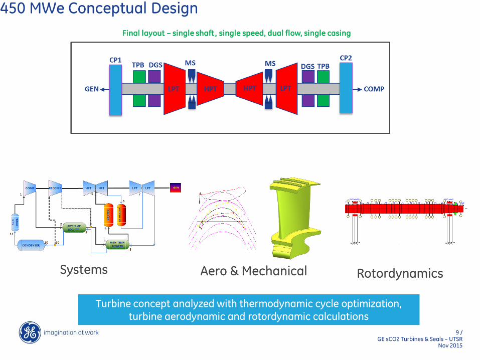
450 MWe Conceptual Design
Final layout – single shaft , single speed, dual flow, single casing
Systems Aero & Mechanical Rotordynamics
Turbine concept analyzed with thermodynamic cycle optimization, turbine aerodynamic and rotordynamic calculations

10 / GE sCO2 Turbines & Seals – UTSR
Nov 2015
450 MWe turbine-compressor layout
SEAL
TPB TC
SEAL TPB
BP
HPT
LPT
SEAL
TPB
TC
CP2
HPT
LPT
SEAL TPB
CP1
Key Features • 450 MW net electric power
• 3600 rpm, single-shaft
• Reheat cycle 52% efficiency
• Single casing dual flow LPT, dual flow HPT
• Single casing back-to-back compressors
11 / GE sCO2 Turbines & Seals – UTSR
Nov 2015
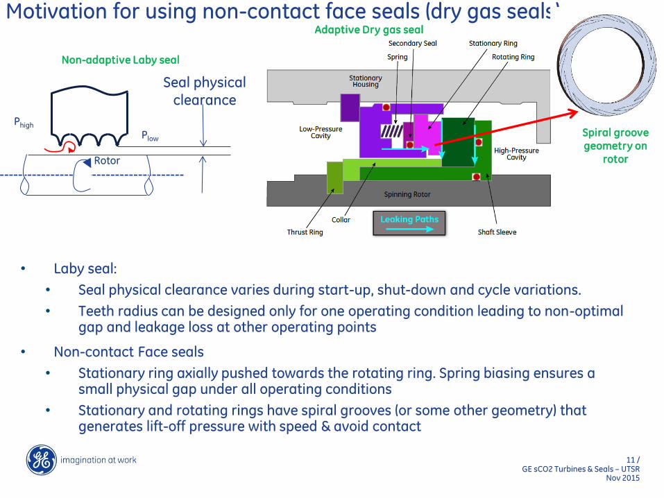
Motivation for using non-contact face seals (dry gas seals)
• Laby seal:
• Seal physical clearance varies during start-up, shut-down and cycle variations.
• Teeth radius can be designed only for one operating condition leading to non-optimal gap and leakage loss at other operating points
• Non-contact Face seals
• Stationary ring axially pushed towards the rotating ring. Spring biasing ensures a small physical gap under all operating conditions
• Stationary and rotating rings have spiral grooves (or some other geometry) that generates lift-off pressure with speed & avoid contact
Rotor
Non-adaptive Laby seal
Phigh
Plow
Seal physical clearance
Adaptive Dry gas seal
Spiral groove geometry on
rotor

12 / GE sCO2 Turbines & Seals – UTSR
Nov 2015
End seals for sCO2 turbines
• sCO2 cycles are unique
• closed loop (unlike open loop gas turbines)
• leaked CO2 needs to be recompressed as vapor (efficiency loss) unlike steam where the end leakage can be condensed to liquid and pumped back
• Seal CO2 leakage has implications for cycle efficiency as well as CO2 replenishment cost
Difference between Steam and CO2 leakage flow compression
End seal layout for a sCO2 turbine

13 / GE sCO2 Turbines & Seals – UTSR
Nov 2015
Turbine End Seal penalty analysis
• 2 x end seals on 450 MWe turbine are worth 0.55% cycle efficiency (1% loss of efficiency is worth $12/KWe)
• Alternate ways of regaining this efficiency (like increasing inlet temperature) are costly compared to developing seals
• Low-leakage seals are an effective method of keeping sCO2 cycles competitive over other power cycles
2 X Turbine End Seals
50.6
50.8
51
51.2
51.4
51.6
51.8
52
52.2
0 0.2 0.4 0.6 0.8 1
Ne
t C
ycl
e E
ffic
ien
cy
(%)
End Seal Total Leakage (% of turbine flow)
Desired Face Seal
Existing
Labyrinth Seal

14 / GE sCO2 Turbines & Seals – UTSR
Nov 2015
Seal Design Challenges
• Maintaining parallelism between rotating & stationary rings is needed for successful seal operation
• Pressure & thermal loads, manufacturability at large diameter limit simple scaling of existing designs
• Innovative seal design features & detailed analysis needed to ensure parallelism
CTQ Value
Diameter 24 inch
Pressure differential > 1000 psi
Seal operating conditions
Force vs. Gap for a face seal (assuming parallel faces)
Deformed rings (rotation converging) 0 0.5 1 1.5 2 2.5 3 3.5
Se
pa
rati
ng
Fo
rce
Rotating-Stationary Ring Gap (1/1000 inch)
< 1/1000 inch
Stationary Ring
Rotating Ring
Stationary Ring
Rotating Ring
Stationary Ring
Rotating Ring
Stationary Ring
Rotating Ring
Deformed rings (rotation & distortion)
Deformed rings (rotation diverging)

15 / GE sCO2 Turbines & Seals – UTSR
Nov 2015
Seal Concept
• Springs & pressure bias the stationary ring towards the rotor
• Spiral grooves generate separating force
• Seal tracks rotor axial transients
Seal stator
Seal stationary
ring
Springs
Casing
Stationary Ring
Rotor
Stator
Spring
Secondary seal
Casing
Stator Stationary
Ring
Rotor
Spiral grooves on the rotor

16 / GE sCO2 Turbines & Seals – UTSR
Nov 2015
sCO2 Seals test rig concept
Skid/frame
Pressure vessel (48” OD)
Electric
motor
CO2 inlet CO2 exit
sCO2 Test Loop Concept
Seal test rig concept developed for high pressure, high temperatures and large diameter seals
17 / GE sCO2 Turbines & Seals – UTSR
Nov 2015
Summary
• sCO2 turbine development at GE
• 10 MWe CSP application
• 450 MWe utility-scale application
• Seal leakage can be significant penalty on cycle efficiency
• Seal concept and analysis, along with a Seals test rig concept

18 / GE sCO2 Turbines & Seals – UTSR
Nov 2015
References 1. Wright, S A, et al. “Summary of the Sandia Supercritical CO2 Development Program,” SCO2 Power Cycle Symposium,
Boulder CO, 2011.
2. Clementoni, E M, et al, “Startup and Operation of a Supercritical Carbon Dioxide Brayton Cycle,” J Eng for Gas Turbines and Power 136, 2014.
3. Kacludis, A, et al, “Waste Heat to Power Applications Using a Supercritical CO2-Based Power Cycle,” Power-Gen International, Orlando FL, 2012
4. Hofer, D. “Development of Supercritical CO2 Power Cycle Applications – The Pathway Forward”, IGTI Turbo Expo, Dusseldorf, Germany, June 2014.
5. Kalra, C. et al. “Development of High Efficiency Hot Gas Turbo-expander for Optimized CSP supercrtical CO2 power block operation,” 4th International SCO2 Power Cycle Symposium, Pittsburgh PA, 2014.
Top Related