


Languages
Pages
Legal


Sandy Butterfield CEO
Boulder Wind Power
WEATS
August 31, 2010
WEATS O&M Issues

Wind Turbines Present Unique O&M Challenges orS!@# Happens & Things Wear Out
• Multiple large machines spread out over large area
• Maintenance planning weather dependent• Consequences of failures can be expensive• Most successful strategies depend on
advanced notice of maintenance requirements
• Remote health monitoring is critical in planning and minimizing maintenance costs
• Research is needed• Certification can be your friend
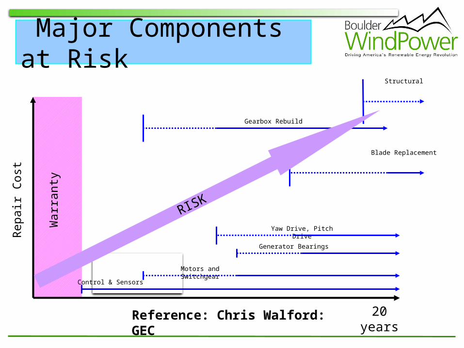
Major Components at Risk
20 years
Rep
air
Cos
t
Gearbox Rebuild
Blade Replacement
Generator Bearings
Yaw Drive, Pitch Drive
Control & Sensors
Motors and Switchgear
War
rant
y
Structural
RISK
Reference: Chris Walford: GEC

4
Land Based O&M Cost Estimations
0.000
0.005
0.010
0.015
0.020
0.025
0 2 4 6 8 10 12 14 16 18 20
Year of Operation
An
nu
al O
&M
Co
st,
$/kW
h
Lemming & Morthorst - 600 kW (1999)
Vachon - 600-740 kW (2002)
Vachon - 2 MW (2002)
WindPACT 1.5 MW - GEC (2003)
WindPACT 1.5 MW - Northern Power (2004)
Chris Walford: GEC
PTC
DOE Goal

5
Where are the Real O&M Costs?Need an Unambiguous Reliability Data Base

6
Benefits of Condition Monitoring Early deterioration
detection to avoid catastrophic failure;
Accurate evaluation of damage state of the monitored structure, and subsequently a cost effective maintenance planning or component replacement;
Root cause analysis and subsequently, improved operational strategy to reduce chances of structure deterioration.
Source: http://jcwinnie.biz/wordpress/?p=2445
Source: Alstom Power

7
Wind Turbine CM
Source: SKF
Source: InvenSys
Components: • Blade• Drive train
Techniques: • Acoustic emission (or
stress wave) analysis • Vibration analysis • Lubricant condition
monitoring
Typical Practice:• Integration of vibration
or stress wave with oil CM
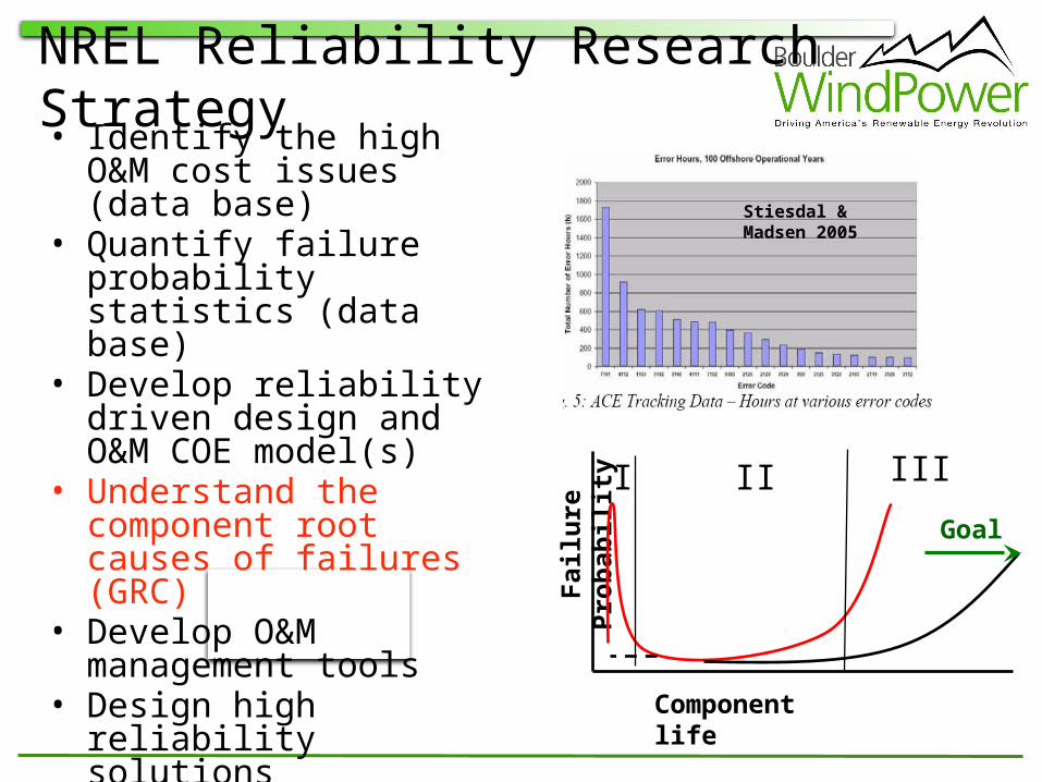
NREL Reliability Research Strategy• Identify the high O&M cost
issues (data base)• Quantify failure probability
statistics (data base)• Develop reliability driven
design and O&M COE model(s)
• Understand the component root causes of failures (GRC)
• Develop O&M management tools
• Design high reliability solutions
• Test solutions and O&M tools at reference sites
• Integrate long term solutions into the design process Component life
Fai
lure
Pro
bab
ilit
y
I II III
Goal
Stiesdal & Madsen 2005
Reliability Program Objectives
• Short Term– Understand reliability issues for current fleet– Help reduce O&M cost of current fleet through
end of life.• Long Term
– Develop high reliability solutions for design integration
– Design high reliability next generation turbines (land based and offshore)
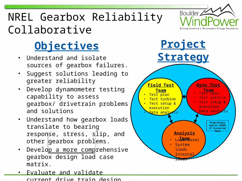
NREL Gearbox Reliability Collaborative
Field Test Team
Dyno Test Team
Analysis Team
• Load cases• System loads• Internal loads
• Test plan• Test article• Test setup &
execution• Data analysis
• Test plan• Test turbine• Test setup &
execution• Data analysis
Proprietary and/or CRADA IP Protected Data
• Understand and isolate sources of gearbox failures.
• Suggest solutions leading to greater reliability
• Develop dynamometer testing capability to assess gearbox/ drivetrain problems and solutions
• Understand how gearbox loads translate to bearing response, stress, slip, and other gearbox problems.
• Develop a more comprehensive gearbox design load case matrix.
• Evaluate and validate current drive train design process and analytical tools.
Objectives Project Strategy
11
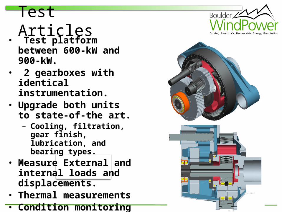
Test Articles• Test platform between 600-
kW and 900-kW.• 2 gearboxes with identical
instrumentation.• Upgrade both units to state-
of-the art.– Cooling, filtration, gear finish,
lubrication, and bearing types.• Measure External and
internal loads and displacements.
• Thermal measurements• Condition monitoring• Expert failure analysis and
forensics
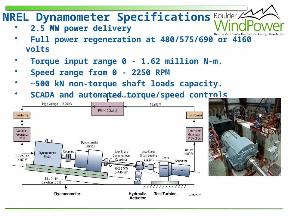
NREL Dynamometer Specifications• 2.5 MW power delivery• Full power regeneration at 480/575/690 or 4160 volts• Torque input range 0 - 1.62 million N-m.• Speed range from 0 - 2250 RPM• ~500 kN non-torque shaft loads capacity.• SCADA and automated torque/speed controls
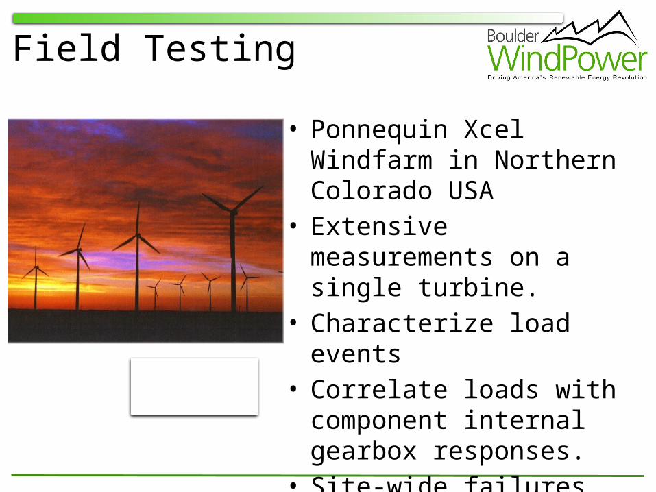
Field Testing
• Ponnequin Xcel Windfarm in Northern Colorado USA
• Extensive measurements on a single turbine.
• Characterize load events • Correlate loads with
component internal gearbox responses.
• Site-wide failures and statistics.
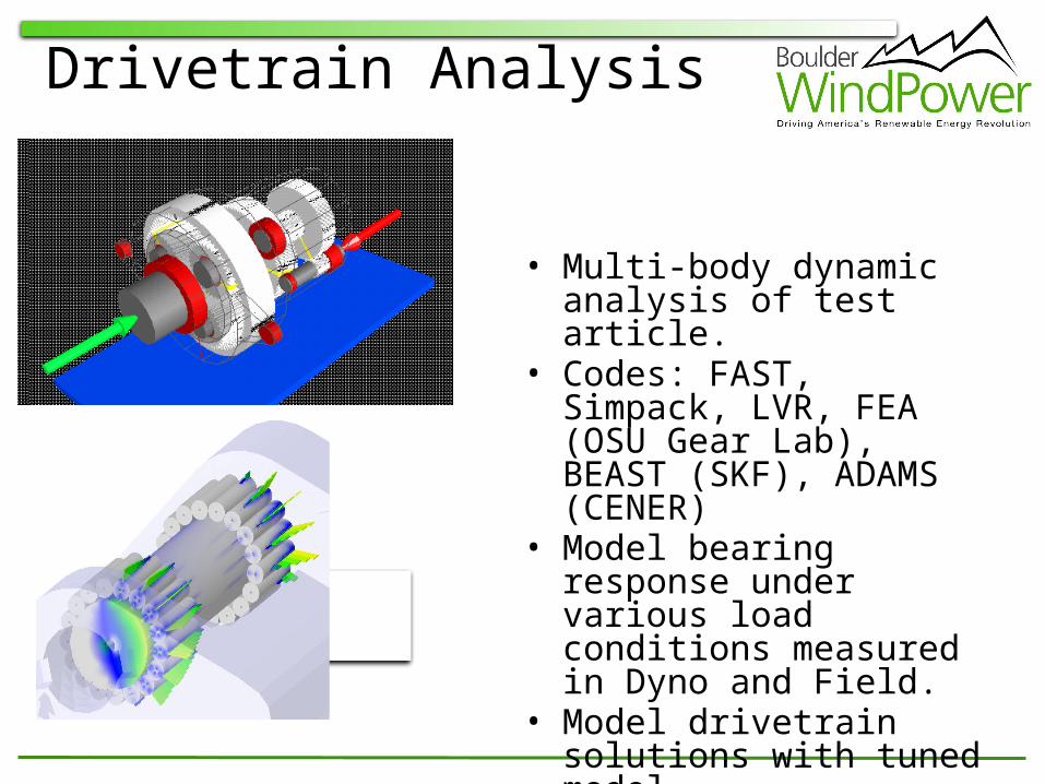
Drivetrain Analysis
• Multi-body dynamic analysis of test article.
• Codes: FAST, Simpack, LVR, FEA (OSU Gear Lab), BEAST (SKF), ADAMS (CENER)
• Model bearing response under various load conditions measured in Dyno and Field.
• Model drivetrain solutions with tuned model.
• Verify design assumptions and basic design process.

Standards and CertificationIEC Turbine Design Classes
R
Cha
ract
eris
tic
Load
, L
L Distribution of Strength
Distribution of Extreme Loads
Pro
ba
bil
ity
Cha
ract
eris
tic
Res
ista
nce,
R
Design Conditions
Table 1 - Basic parameters for wind turbine classes1
Wind Turbine Class I II III S
Vref (m/s) 50 42,5 37.5 Values
A Iref (-) 0,16 Specified
B Iref (-) 0,14 by the
C Iref (-) 0,12 Designer
1 The annual average wind speed no longer appears in Table 1 as a basic parameter for the wind turbine classes in this edition of the standard. The annual average wind speed for wind turbine designs accordi ng to these classes is given in (9).
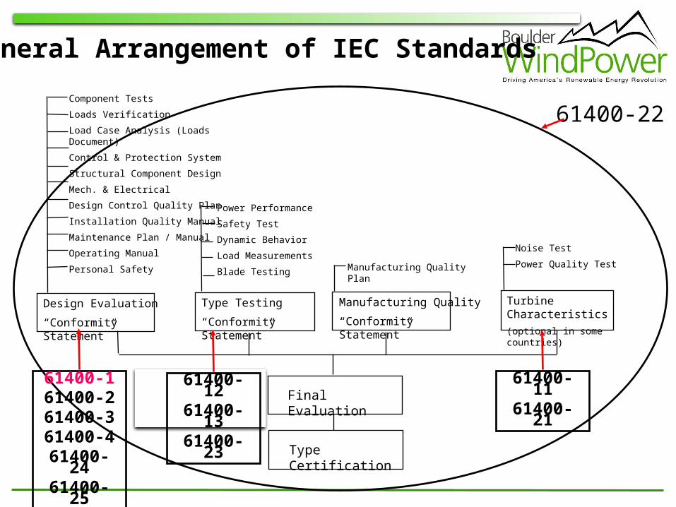
Design Evaluation
“Conformity Statement”
Component Tests
Loads Verification
Load Case Analysis (Loads Document)
Control & Protection System
Structural Component Design
Mech. & Electrical
Design Control Quality Plan
Installation Quality Manual
Maintenance Plan / Manual
Operating Manual
Personal Safety
Type Testing
“Conformity Statement”
Noise Test
Power Quality Test
Manufacturing Quality
“Conformity Statement”
Manufacturing Quality Plan
Type Certification
Power Performance
Safety Test
Dynamic Behavior
Load Measurements
Blade Testing
Turbine Characteristics
(optional in some countries)
Final Evaluation
General Arrangement of IEC Standards
61400-161400-261400-361400-461400-2461400-25
61400-1261400-1361400-23
61400-1161400-21
61400-22
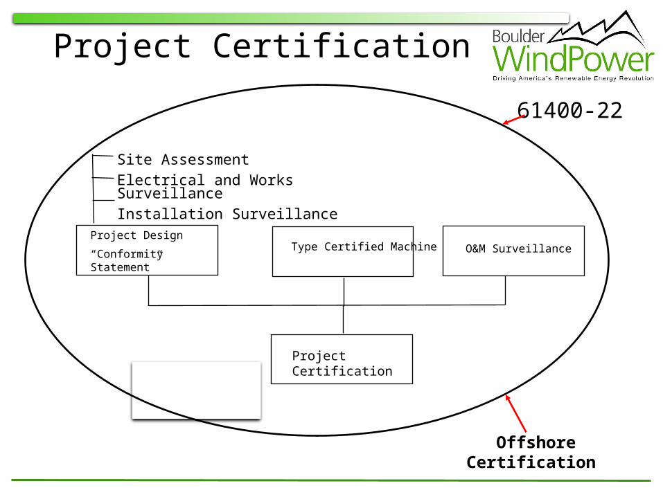
O&M Surveillance
Site Assessment
Electrical and Works Surveillance
Installation Surveillance
Type Certified Machine
Project Certification
Project Design
“Conformity Statement”
Project Certification
Offshore Certification
61400-22

Thank You!