


Languages
Pages
Legal

1
Safety studies for MYRRHA
B. Arien, S. Heusdains, H. Aït Abderrahim
on behalf of the MYRRHA Team and Support
IP-Eurotrans Workshop DM1-WP1.5 Brussels, March 17, 2006

2
Contents
• 3 topics Enhancement of free convection LBE freezing in heat exchangers TH modelling of the spallation loop with
RELAP
• Future work

3
Enhancement of free convection
• Unprotected total LOF and LOH accidents are beyond MYRRHA Draft_2 design
• 2 possible ways to improve natural circulation: by increasing the H between core and HXs by reducing the pressure losses
• First investigations with a simplified model loop model simulating the pool type system SITHER code provided with a free convection module
(SITHER-FC) results are indicative

4
Reminder (PDS-XADS) : TH analysis results for
unprotected accidents (I)
Transient Fuel Clad LBE Water
LOF Partial (1 EHX check valve failed)
OK OK OK OK
LOF Partial (1 pump trip):
OK OK OK OK LOF Total (4 pumps trip):
OK T > 700°C after 7 s
OK OK TOP (410 pcm) OK OK OK OK LOH Partial (1 SCS failed):
OK OK OK OK LOH Total (2 SCS failed):
OK T > 700°C after 9 min
OK Boiling after 20 min
Partial LOF + Partial LOH
OK OK OK OK Total LOF + Total LOH
Melting after 20 min
T > 700°C after 5 s
OK Boiling after 1 min
Overcooling OK OK Freezing after 14 min in PHX
5 min in EHX
OK

5
Reminder (PDS-XADS): TH analysis results for unprotected accidents
(II)
Transient Fuel Clad LBE Water
SA blockage (2.5%) OK Failure OK Spurious beam start-up OK OK OK

6
Enhancement of free convection: strategy of computation
Start from SITHER-FC as originally developed for preliminary studies in the MYRRHA project free parameters
Calibrate SITHER-FC (free parameters) from Draft_2 design and results obtained with RELAP
2 possible options for the HXs in emergency:
Emergency HXs (draft_2 design): EHX
Primary HXs: PHX
Effect of H increase (H: difference of elevation between core and HXs)
Effect of pressure loss reduction over the core
Note: spallation loop behaviour in transient conditions not taken into account in the present study (very conservative)

7
G: mass flow rate C: inertial coefficient pF: friction pressure losses (=f(G))
pP: pump pressure head 0 in fc mode
pB: “buoyancy” pressure
BPF pΔpΔpΔtG
C
HΔTΔgρβpΔ B
Momentum equation in the loop model:
• mass conservation• momentum conservation• energy conservation (core , HXs, pipes)
Enhancement of free convection: simplified loop model

8
Enhancement of free convection: SITHER calibration – unprotected LOF
case
200
400
600
800
1000
1200
1400
0 300 600 900 1200 1500t(s)
Tcl (
°C)
RELAP
SITHER
1600
1700
1800
1900
2000
2100
2200
2300
2400
0 300 600 900 1200 1500t(s)
Tf (
°C)
RELAP
SITHER
max. fuel temperature max. clad temperature
core mass flow rate temperatures in EHX
0
500
1000
1500
2000
2500
0 300 600 900 1200 1500t (s)
G (
kg
/s)
RELAP
SITHER
100
300
500
700
900
1100
0 300 600 900 1200 1500t (s)
TE
HX (
°C)
EHX outlet RELAP
EHX inlet RELAP
EHX outlet SITHEREHX inlet SITHER

9
Enhancement of free convection: effect of H increase
200
300
400
500
600
0 300 600 900 1200 1500t (s)
T cl (
°C)
PHX: high core position
PHX: low core position
EHX: high core position
EHX: low core position
200
400
600
800
1000
1200
1400
1600
1800
2000
0 300 600 900 1200 1500t (s)
T f (°
C)
PHX: high core position
PHX: low core position
EHX: high core position
EHX: low core position
1600
1800
2000
2200
2400
0 300 600 900 1200 1500t (s)
T f (°
C)
PHX: high core positionPHX: low core positionEHX: high core positionEHX: low core position
max. fuel temperature - PLOF max. clad temperature - PLOF
max. fuel temperature - ULOF max. clad temperature - ULOF
200
400
600
800
1000
1200
1400
1600
0 300 600 900 1200 1500t (s)
T cl (
°C)
PHX: high core positionPHX: low core positionEHX: high core positionEHX: low core position
PHX EHX
high core
0.81 1.67
low core
3.0 4.0
H (m)

10
Enhancement of free convection: effect of pF
reduction
1500
1800
2100
2400
0 300 600 900 1200 1500t (s)
T f (°
C)
100% Dpcore
50% Dpcore
25% Dpcore
200
500
800
1100
1400
0 300 600 900 1200 1500t (s)
T cl (
°C)
100% Dpcore
50% Dpcore
25% Dpcore
1500
1800
2100
2400
0 300 600 900 1200 1500t (s)
T f (°
C)
100% Dpcore
50% Dpcore
25% Dpcore
max. fuel temperature - ULOF max. clad temperature - ULOF
200
400
600
800
1000
1200
1400
0 300 600 900 1200 1500t (s)
T cl (
°C)
100% Dpcore
50% Dpcore
25% Dpcore
EHX
PHX
11
Enhancement of free convection: conclusions
• Effect of H increase: Even with large H emergency EHXs are not able to
keep core integrity in case of unprotected LOF accident (EHXs are not designed to evacuate nominal power)
Use of PHXs in emergency situations allows to mitigate strongly the unprotected LOF effects
• Effect of pcore reduction:relatively small benefit
• Behaviour of spallation loop should be taken into account

12
LBE freezing in heat exchangers
• LBE freezing in HXs can occur with overcooling in secondary circuit
• In extreme conditions plugging could occur
• If total plugging possibility of LOF & LOH
• Difficulty to recover the normal operation in case of plugging

13
LBE freezing in heat exchangers: HX types
Option 1: pressurized water Option 2: boiling water
lead-bismuth
water

14
LBE freezing in heat exchangers: model (I)
liquid LBE
solid LBE
water tube
0drdT
krdrd
r1
ff TThφ wewe TThφ
• Code WALEBI (LBE/water HX) updated for freezing
• Purely thermal model
• Mechanical effects are not taken into account (conservative)
15
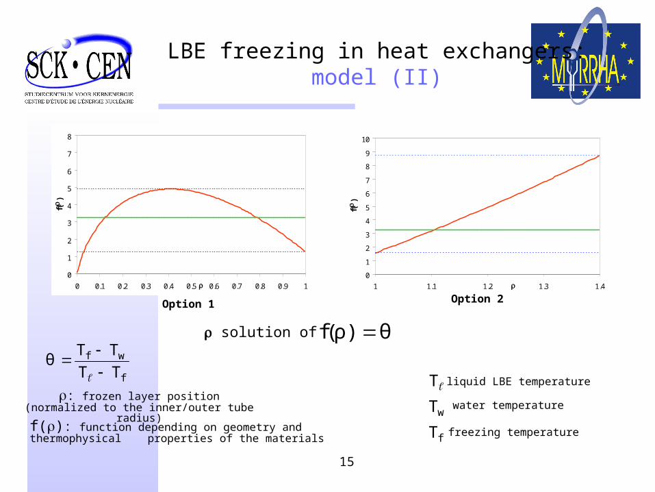
LBE freezing in heat exchangers: model (II)
0
1
2
3
4
5
6
7
8
0 0.1 0.2 0.3 0.4 0.5 0.6 0.7 0.8 0.9 1r
f(r
)
q
q1
q2
0
1
2
3
4
5
6
7
8
9
10
1 1.1 1.2 1.3 1.4r
f(r
)
q
q2
q1
Option 1 Option 2
θ)ρ(f
f
wf
TTTT
θ
f(r): function depending on geometry and thermophysical properties of the materials
T liquid LBE temperature
wT water temperature
fT freezing temperature
r: frozen layer position (normalized to the inner/outer tube radius)
r solution of
16
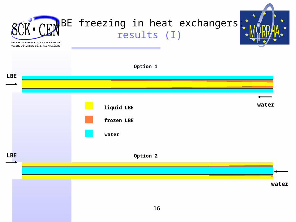
LBE freezing in heat exchangers: results (I)
liquid LBE
frozen LBE
LBE
water
water
water
LBE
Option 1
Option 2

17
LBE freezing in heat exchangers: results (II)
0.0
0.2
0.4
0.6
0.8
1.0
0 20 40 60 80 100 120 140 160Tw (°C)
s
Frozen layer thickness
Option 1 Option 2
s: frozen layer thickness normalized to the inner/outer clad radius
Tw: water inlet temperature
Total freezing
0.0
0.1
0.2
0.3
0.4
0 20 40 60 80 100 120 140 160Tw (°C)
s
Total freezing

18
LBE freezing in heat exchangers: conclusions
• Risk of tube plugging seems negligible
• Freezing is less important with option 2

19
TH modelling of the spallation loop: general sketch

20
TH modelling of the spallation loop: RELAP model

21
TH modelling of the spallation loop : results
100.81
0
20
40
60
80
100
120
140
0 1000 2000 3000 4000 5000 6000t(s)
Mas
s flo
w r
ate
(kg/
s)
0
0.5
1
1.5
2
2.5
0 1000 2000 3000 4000 5000 6000t (s)
L
(m)
Mass flow rate Difference of free surface levels

22
Future work
• Input from and interaction with designers (WP1.1, WP1.2, WP1.4) are imperative
• TH modelling of XT-ADS with RELAP
• CFD simulation of XT-ADS primary system with FINE\HEXA (SCKCEN) and CFX (NRG): forced convection and free convection
• Optimization of the emergency cooling system
• …
Top Related