


Languages
Pages
Legal


Southwest Microwave, Inc. Tempe, Arizona 85284 USA 480-783-0201 www.southwestmicrowave.com
TNC
Connectors
N Series
Connectors
Super SMA
Connectors
SSM
AC
onnectors 2.92 m
mC
onnectors 2.40 m
m
Connectors
Adapters
End LaunchC
onnectorsC
ableC
onnectorsInstallation
and ToolsLaunch
Accessories
93
Appendix
Unless otherwise specified, all dimensions are in inches.
Index
S-Level and Hi-Rel Connectors . . . . . . . . . . . . . . . . . 94
Power Rating for Coaxial Connectors . . . . . . . . . . . . 98
Mounting GuidelinesFor Flange Mount Connectors . . . . . . . . . . . . . . . . . 102
Mating Microwave Connectors . . . . . . . . . . . . . . . . . 105
RF Versus Microwave SMA Connectors . . . . . . . . . . . 106
EMI/RFI Shielding Standards . . . . . . . . . . . . . . . . . . 108
Materials Commonality in Connectors . . . . . . . . . . . . 110
Connector Compatibility (Intermateability) . . . . . . . . . 110
Appendix . . . . . . . . . . . . . . . . . . . . . . . . . . . . . . . . Page

Southwest Microwave, Inc. Tempe, Arizona 85284 USA 480-783-0201 www.southwestmicrowave.com
Cab
leC
onne
ctor
sLa
unch
Acc
esso
ries
Inst
alla
tion
and
Tool
sS
SMA
Con
nect
ors
End
Lau
nch
Con
nect
ors
2.4
0 m
m
Con
nect
ors
Ada
pter
s 2
.92
mm
Con
nect
ors
TNC
Con
nect
ors
Supe
r SM
AC
onne
ctor
s N
Ser
ies
Con
nect
ors
94
outhwest Microwave has been delivering S-Level (Space)
and Hi-Rel connectors since 1991.
Use of Southwest Microwave connectors in these applications is impor-
tant to achieving final systemic results. A list of S-Level / Hi-Rel custom-
ers using Southwest Microwave connectors include:
Features:
COTS (commercial-off-the-shelf) connectors can be up screened for space level jobs.
to 165o C, all others rated to 135o C (Max operation 165o C).
Industry lowest VSWR and RF leakage.
All materials used in Southwest connectors are lot-traceable to raw material.
All materials meet NASA’s requirements for outgassing.
Center conductors rigidly captured with hi-temp mechanical bead.
S
Anaren
Boeing Satellite
Boeing Defense
EADS Astrium
Elta Electronics
General Dynamics
Harris Corp.
Hughes Space
India Space Application Center
JPL
L3 Narda
L3 Communications
L3 Satellite Networks
Lockheed Martin
Miteq
Merrimac Industries
Motorola
Northrop Grumman
NASA Langley
Space Systems/Loral
Tecnológica
Teledyne
TRW Space
S-Level and Hi-Rel ConnectorsFor Military & Spaceflight Applications
Partial Customer List
TM

Southwest Microwave, Inc. Tempe, Arizona 85284 USA 480-783-0201 www.southwestmicrowave.com
TNC
Connectors
N Series
Connectors
Super SMA
Connectors
SSM
AC
onnectors 2.92 m
mC
onnectors 2.40 m
m
Connectors
Adapters
End LaunchC
onnectorsC
ableC
onnectorsInstallation
and ToolsLaunch
Accessories
95
Connector type Freq
Super SMA 27 GHz2.92 mm 40 GHz2.40 mm 50 GHzTNC 18 GHzN 18 GHzSSMA 36 GHz
TM
Southwest Microwave Recommended Test Plans (see next page)
Southwest Microwave uses MIL-PRF-39012 as a refer-ence for interface specifications and test methods. There are additional tests SMI recommends be performed in addition to MIL-PRF-39012 to ensure proper performance during the actual usage of the connectors. The most im-portant of these is thermal shock to ensure the interface and the electrical performance are stable over the full temperature range. MIL-PRF-39012 does not require test-ing after temperature cycling.
COTS Considerations Outgassing: All material used in connector assemblies meet NASA outgassing requirements. (See page 97)
Material Traceability: All material used in connector as-semblies has traceability to raw material. This allows SMI to use any item in stock for space level applications.
Single Lot Control: SMI builds to stock in large quantities so small quantities requiring single lot control of all raw materials are usually available in stock.
Source Control Drawings (SCD): SMI has an exten-sive database of customer source control drawings for commercial and hi-rel applications. Due to extensive experience working with SCD’s, SMI is frequently asked to contribute technical material and assistance in their creation.
Space Screening: Test plans are generated in ac-cordance with SCD requirements and most tests are performed in-house. Tests are performed and the results recorded in accordance with the test plan. The results are then combined with material certs and lot traceability information into a document called an Acceptance Test Report (ATR).
Destructive Physical Analysis (DPA): When DPA is re-quired, SMI works with several quality labs that provide DPA services. SMI oversees the testing and integrates the DPA results into the ATR.
Qualification Testing: SMI can perform most of these tests in-house and will coordinate with outside labs for those other tests, such as shock and vibration that require special equipment. SMI will design and build the necessary tools to facilitate these tests.
Source Inspections: SMI has hosted many source in-spections in coordination with several major space and hi-rel customers, and is familiar with what is required to facilitate and streamline them.
Southwest Microwave connectors
are ideal in military and space flight
applications where power management
and low loss interconnects are critical.
SMI connectors have the lowest VSWR in
the industry, with typical VSWR of 1.10 : 1
(return loss of -26 dB) up to 50 GHz.
SMI offers the additional advantage
of low RF leakage of <-100 dB typical.
S-Level and Hi-Rel ConnectorsFor Military & Spaceflight Applications

Southwest Microwave, Inc. Tempe, Arizona 85284 USA 480-783-0201 www.southwestmicrowave.com
Cab
leC
onne
ctor
sLa
unch
Acc
esso
ries
Inst
alla
tion
and
Tool
sS
SMA
Con
nect
ors
End
Lau
nch
Con
nect
ors
2.4
0 m
m
Con
nect
ors
Ada
pter
s 2
.92
mm
Con
nect
ors
TNC
Con
nect
ors
Supe
r SM
AC
onne
ctor
s N
Ser
ies
Con
nect
ors
96
SOUTHWEST MICROWAVE RECOMMENDED ACCEPTANCE TEST TABLES
TABLE I - General Product Assurance(Derived from group A requirements)
TABLE II - Product Performance Assurance(Derived from group B requirements with thermal shock added)
MIL-PRF-39012REQUIREMENT
REFERENCEPARAGRAPH
INSPECTION TYPE(Visual and Mechanical Examination)
MIL-PRF-39012TEST METHOD
REFERENCEPARAGRAPH
RECOMMENDEDMIL-PRF-39012SAMPLE SIZE
MATERIALFINISHDISSIMILAR METALSMARKINGWORKMANSHIP
3.33.3.13.3.23.293.30
TABLE I------
MIL-STD-889MIL-STD-130
------
C of Cs
C of Cs
100%100%100%
INSPECTION TYPE(Design and Construction Testing)
MIL-PRF-39012REQUIREMENT
REFERENCEPARAGRAPH
MIL-PRF-39012TEST METHOD
REFERENCEPARAGRAPH
RECOMMENDEDMIL-PRF-39012SAMPLE SIZE
CONFIGURATION AND FEATURESCONTACT GAGING (mating characteristics)
CONTACT RETENTIONVSWRINSERTION LOSSCONNECTOR INTERFACES
THERMAL SHOCK
CONTACT GAGING (mating characteristics)
CONTACT RETENTIONVSWRINSERTION LOSSCONNECTOR INTERFACESDIELECTRIC WITHSTANDING VOLTAGE
Note: SMI recommends testing before and after thermal shockto ensure proper operation in space environments.
3.43.73.123.143.273.4.3
3.20
3.73.123.143.273.4.33.17
FIGURES4.7.44.7.94.7.114.7.24
MIL-STD-348
4.7.17
4.7.44.7.94.7.114.7.24
MIL-STD-3484.7.14
Table IVTable IVTable IVTable VITable VITable IV
100%
Table IVTable IVTable VITable VITable IV
100%

Southwest Microwave, Inc. Tempe, Arizona 85284 USA 480-783-0201 www.southwestmicrowave.com
TNC
Connectors
N Series
Connectors
Super SMA
Connectors
SSM
AC
onnectors 2.92 m
mC
onnectors 2.40 m
m
Connectors
Adapters
End LaunchC
onnectorsC
ableC
onnectorsInstallation
and ToolsLaunch
Accessories
97
List of materials used by SMI:
a) PTFE Fluorocarbon Insulatorb) Vary Flex Epoxy Polyamide
c) *ULTEM 1000d) **KEL-F
S-Level and Hi-Rel ConnectorsFor Military & Spaceflight Applications
*ULTEM IS A trademark of General Electric, Inc. **KEL-F IS A trademark of 3M Company.
IS A trademark of Southwest Microwave, Inc.
Southwest Microwave, Inc. www.southwestmicrowave.com9055 South McKemy Street - Tempe, Arizona 85284- Telephone 480-783-0201 FAX 480-783-0401

Southwest Microwave, Inc. Tempe, Arizona 85284 USA 480-783-0201 www.southwestmicrowave.com
Cab
leC
onne
ctor
sLa
unch
Acc
esso
ries
Inst
alla
tion
and
Tool
sS
SMA
Con
nect
ors
End
Lau
nch
Con
nect
ors
2.4
0 m
m
Con
nect
ors
Ada
pter
s 2
.92
mm
Con
nect
ors
TNC
Con
nect
ors
Supe
r SM
AC
onne
ctor
s N
Ser
ies
Con
nect
ors
98
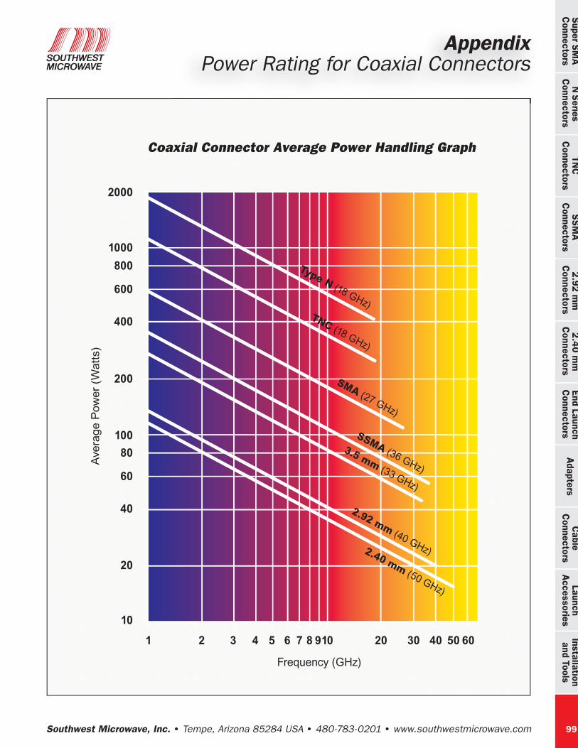
AppendixPower Rating for Coaxial Connectors
Average Power Ratings for Coaxial Connectors
The following graph summarizes industry acceptable average power rating for a variety of coaxial connector types. The key characteristic that determines average power handling capabilities for mated coaxial connectors is its ability to pass high current and keep heat-rise to a moderate temperature. This heating directly relates to contact resistance. Contact resistance is a function of contact surface area. Therefore properly formed center contacts are critical. If connectors are long, then conductor length resistance may start to dominate. The average power rating decreases with frequency because the resistive losses increase with frequency.
High power failure is caused by the generation of heat at the contacting surfaces. When the contact resistance approaches surface resistance including skin effect, the ultimate power handling level will be approached. Application results are affected by heat-sinking of the connector plus the connector’s construction and use of higher-temperature materials. Another limiting factor is altitude because of the connector's increasing inability to dissipate heat as altitude increases. Power derating factors for temperature and altitude are provided on the following table.
Thus, there is not an absolute power handling figure for a connector type. Results may vary from supplier-to-supplier due to design, materials and manufacturing latitudes taken by each. Therefore published power ratings are typically conservative.
Extended Power Super SMASouthwest Microwave’s “Extended Power Super SMA” connectors provide additional power handling capabilities above most standard SMA connectors because they operate reliably at higher temperatures (165°C) with moderate power (160W) or at higher / extended power (250W) at 125°C. The temperature rating as specified is the tempera-ture that the connector will withstand and still meet the electrical specifications.
As a basic guideline, the Extended Power Super SMA will handle an additional 100W average power above what is represented in the following power chart for SMA. There-fore the recommended maximum power rating for Extended Power Super SMA connec-tor is 250W CW at Ku-band (12.4–18.0 GHz), at a maximum temperature of 125°C.
Southwest Microwave, Inc. Tempe, Arizona 85284 USA 480-783-0201 www.southwestmicrowave.com
TNC
Connectors
N Series
Connectors
Super SMA
Connectors
SSM
AC
onnectors 2.92 m
mC
onnectors 2.40 m
m
Connectors
Adapters
End LaunchC
onnectorsC
ableC
onnectorsInstallation
and ToolsLaunch
Accessories
99
2000
1000
800
600
400
200
100
80
60
40
20
10
1 2
Frequency (GHz)
Type N (18 GHz)TNC (18 GHz)
SMA (27 GHz)
2.92 mm (40 GHz)2.40 mm (50 GHz)
SSMA (36 GHz)
3.5 mm (33 GHz)
Coaxial Connector Average Power Handling Graph
Ave
rage P
ow
er
(Wat
ts)
3 4 5 6 7 8 910 20 30 40 50 60
AppendixPower Rating for Coaxial Connectors

Southwest Microwave, Inc. Tempe, Arizona 85284 USA 480-783-0201 www.southwestmicrowave.com
Cab
leC
onne
ctor
sLa
unch
Acc
esso
ries
Inst
alla
tion
and
Tool
sS
SMA
Con
nect
ors
End
Lau
nch
Con
nect
ors
2.4
0 m
m
Con
nect
ors
Ada
pter
s 2
.92
mm
Con
nect
ors
TNC
Con
nect
ors
Supe
r SM
AC
onne
ctor
s N
Ser
ies
Con
nect
ors
100
AppendixPower Rating for Coaxial Connectors

Southwest Microwave, Inc. Tempe, Arizona 85284 USA 480-783-0201 www.southwestmicrowave.com
TNC
Connectors
N Series
Connectors
Super SMA
Connectors
SSM
AC
onnectors 2.92 m
mC
onnectors 2.40 m
m
Connectors
Adapters
End LaunchC
onnectorsC
ableC
onnectorsInstallation
and ToolsLaunch
Accessories
101
AppendixPower Rating for Coaxial Connectors

Southwest Microwave, Inc. Tempe, Arizona 85284 USA 480-783-0201 www.southwestmicrowave.com
Cab
leC
onne
ctor
sLa
unch
Acc
esso
ries
Inst
alla
tion
and
Tool
sS
SMA
Con
nect
ors
End
Lau
nch
Con
nect
ors
2.4
0 m
m
Con
nect
ors
Ada
pter
s 2
.92
mm
Con
nect
ors
TNC
Con
nect
ors
Supe
r SM
AC
onne
ctor
s N
Ser
ies
Con
nect
ors
102
AppendixMounting Guidelines for Flange Mount Connectors

Southwest Microwave, Inc. Tempe, Arizona 85284 USA 480-783-0201 www.southwestmicrowave.com
TNC
Connectors
N Series
Connectors
Super SMA
Connectors
SSM
AC
onnectors 2.92 m
mC
onnectors 2.40 m
m
Connectors
Adapters
End LaunchC
onnectorsC
ableC
onnectorsInstallation
and ToolsLaunch
Accessories
103
AppendixMounting Guidelines

Southwest Microwave, Inc. Tempe, Arizona 85284 USA 480-783-0201 www.southwestmicrowave.com
Cab
leC
onne
ctor
sLa
unch
Acc
esso
ries
Inst
alla
tion
and
Tool
sS
SMA
Con
nect
ors
End
Lau
nch
Con
nect
ors
2.4
0 m
m
Con
nect
ors
Ada
pter
s 2
.92
mm
Con
nect
ors
TNC
Con
nect
ors
Supe
r SM
AC
onne
ctor
s N
Ser
ies
Con
nect
ors
104
AppendixMounting Guidelines

Southwest Microwave, Inc. Tempe, Arizona 85284 USA 480-783-0201 www.southwestmicrowave.com
TNC
Connectors
N Series
Connectors
Super SMA
Connectors
SSM
AC
onnectors 2.92 m
mC
onnectors 2.40 m
m
Connectors
Adapters
End LaunchC
onnectorsC
ableC
onnectorsInstallation
and ToolsLaunch
Accessories
105
AppendixMating Microwave Connectors
Do Not Allow to Rotate
Rota
te C
oupl
ing
Nut O
nly
Rota
te C
oupl
ing
Nut O
nly
Rota
te C
oupl
ing
Nut O
nly
Proper Procedure for Mating Microwave Connectors
1. Engage the two mating interfaces with slight pressure.
2. Hold the body of the male connector and turn only the coupling nut.
• The coupling nut will engage the threads of the female connector.
3. Continue turning only the coupling nut.
• The outer conductors will engage and align the connectors to each other.
• Then the center conductors will engage.
• Then the outer conductors (reference planes) will come together and the coupling nut will quit turning.
4. Use a torque wrench to apply the proper torque to complete the mating.
When the proper procedure for mating mi-crowave connectors is followed, no rotational torque is applied to the center conductors. If the body of either connector is rotated, this is improper and can apply a rotational torque to the center conductor. All Southwest Micro-wave connectors have the center conductor rigidly captured to the outer housing. The center conductor captivation is, in most cases, accomplished with a high temperature plastic bead. This bead provides high axial reten-tion at extended temperatures, but does not provide for any rotational resistance. Therefore proper mating is strongly recommended.
Outer conductor and threads starting to engage.
Outer conductor and threads engaged, center conductor starting to engage.
Outer conductor fully engaged – connectors are fully mated.

Southwest Microwave, Inc. Tempe, Arizona 85284 USA 480-783-0201 www.southwestmicrowave.com
Cab
leC
onne
ctor
sLa
unch
Acc
esso
ries
Inst
alla
tion
and
Tool
sS
SMA
Con
nect
ors
End
Lau
nch
Con
nect
ors
2.4
0 m
m
Con
nect
ors
Ada
pter
s 2
.92
mm
Con
nect
ors
TNC
Con
nect
ors
Supe
r SM
AC
onne
ctor
s N
Ser
ies
Con
nect
ors
106
AppendixRF Versus Microwave SMA Connectors

Southwest Microwave, Inc. Tempe, Arizona 85284 USA 480-783-0201 www.southwestmicrowave.com
TNC
Connectors
N Series
Connectors
Super SMA
Connectors
SSM
AC
onnectors 2.92 m
mC
onnectors 2.40 m
m
Connectors
Adapters
End LaunchC
onnectorsC
ableC
onnectorsInstallation
and ToolsLaunch
Accessories
107
AppendixRF Versus Microwave SMA Connectors

Southwest Microwave, Inc. Tempe, Arizona 85284 USA 480-783-0201 www.southwestmicrowave.com
Cab
leC
onne
ctor
sLa
unch
Acc
esso
ries
Inst
alla
tion
and
Tool
sS
SMA
Con
nect
ors
End
Lau
nch
Con
nect
ors
2.4
0 m
m
Con
nect
ors
Ada
pter
s 2
.92
mm
Con
nect
ors
TNC
Con
nect
ors
Supe
r SM
AC
onne
ctor
s N
Ser
ies
Con
nect
ors
108
AppendixEMI/RFI Shielding Standards

Southwest Microwave, Inc. Tempe, Arizona 85284 USA 480-783-0201 www.southwestmicrowave.com
TNC
Connectors
N Series
Connectors
Super SMA
Connectors
SSM
AC
onnectors 2.92 m
mC
onnectors 2.40 m
m
Connectors
Adapters
End LaunchC
onnectorsC
ableC
onnectorsInstallation
and ToolsLaunch
Accessories
109
AppendixEMI/RFI Shielding Standards

Southwest Microwave, Inc. Tempe, Arizona 85284 USA 480-783-0201 www.southwestmicrowave.com
Cab
leC
onne
ctor
sLa
unch
Acc
esso
ries
Inst
alla
tion
and
Tool
sS
SMA
Con
nect
ors
End
Lau
nch
Con
nect
ors
2.4
0 m
m
Con
nect
ors
Ada
pter
s 2
.92
mm
Con
nect
ors
TNC
Con
nect
ors
Supe
r SM
AC
onne
ctor
s N
Ser
ies
Con
nect
ors
110
AppendixMaterials Commonality / Connector Compatibility
Materials Commonality in Connectors
Connector Intermateability
Connector Type . . . . . . . . . . . . . . . . . . Compatible with:
1.85 mm . . . . . . . . . . . . . . . . . . . . . 2.40 mm
2.40 mm . . . . . . . . . . . . . . . . . . . . . 1.85 mm
2.92 mm . . . . . . . . . . . . . . . . . . . . . 3.5 mm & SMA
3.5 mm . . . . . . . . . . . . . . . . . . . . . 2.92 mm & SMA
SMA . . . . . . . . . . . . . . . . . . . . . . . . 2.92 mm & 3.5 mm
Teflon™ Dielectric
N ConnectorsTNC ConnectorsSuper SMA Connectors *SSMA Connectors
Common Construction:
Housing: Stainless Steel, Passivated
Contact: Beryllium Copper (BeCu) Gold Plated Per MIL-G-45204
Teflon Construction:
Dielectric: PTFE Fluorocarbon Per ASTM D1710
Center Contact Capture: Single Bead Capture with Ultem 1000 Per ASTM D5205
Temperature Rating -55°C to +165°C
Air Dielectric (Airline)
3.5 mm Connectors2.92 mm Connectors2.40 mm Connectors1.85 mm Connectors
Common Construction:
Housing: Stainless Steel, Passivated
Contact: Beryllium Copper (BeCu) Gold Plated Per MIL-G-45204
Airline Construction:
Center Contact Capture: Rigid Two Bead Capture with Ultem 1000 Per ASTM D5205 and KEL-F Per ASTM D1430 or PTFE Fluorocarbon Per ASTM D1710
Temperature Rating -55°C to +135°C
Note: Direct Solder Cable Connectors May Differ. Check Catalog Sections for Data.
Top Related