
![Pile Design for Structural and Geotechnical Engineers - Rajapakse[1]](https://static.fdocuments.us/doc/165x107/544c0105af7959ac438b582b/pile-design-for-structural-and-geotechnical-engineers-rajapakse1.jpg)


Languages
Pages
Legal


R Consulting Engineers Rybak Geotechnical, Inc.
16022 Arminta Street, Ste. #7, Van Nuys, CA 91406 · (818) 785-0550 · www.rybakgeotechnical.com
Geotechnical Engineering Investigation
Proposed Parkpointe Encino Project
4929 Genesta Avenue and 17017 Ventura Boulevard
Encino, California
For
TRISTAR REALTY GROUP, LLC
Project No. 2908 February 24, 2017

Rybak Geotechnical, Inc. Consulting Engineers __ ... ________________________ llliiiila_:+
.....,...,....,.. 16022 Arminta Street, Ste. #7, Van Nuys, CA 91406 • (818) 785-0550 • www.rybakgeotechnical.com
February 24, 2017 Project No. 2908
Tristar Realty Group, LLC 12502 Van Nuys Blvd., Suite 301 Pacoima, California 91331
Attn: Daniel Kashani
Dear Mr. Kashani:
We are pleased to submit our report on a geotechnical engineering investigation performed for the proposed Parkpointe Encino project to be located at 4929 Genes ta A venue and 17017 Ventura Blvd., in the Encino area of the City of Los Angeles, California. Our geotechnical engineering conclusions and recommendations are presented in this report.
Four wet-signed, wet-stamped copies of the report, along with a PDF on CD, have been transmitted herewith. It should be noted that no copies of this report have been submitted by us to any other individuals or agencies. Please review the report; if satisfactory, distribute the unbound copies to the applicable agencies and pay any required filing fee. To the best of our knowledge, two wetsigned/wet-stamped copies, along with a PDF copy on CD, should be submitted to the City of Los Angeles Department of Building and Safety, Grading Division. Should you have any questions regarding the report or this submittal, please do not hesitate to call.
RICHARD RYBAK President
INC.

R Rybak Geotechnical, Inc. 16022 Arminta Street, Ste. #7, Van Nuys, CA 91406 · (818) 785-0550 · www.rybakgeotechnical.com
Proposed Parkpointe Encino Project February 24, 2017
4929 Genesta Avenue and 17017 Ventura Boulevard, Encino, California Project No. 2908
Table of Contents INTRODUCTION .......................................................................................................................... 1
INTENT .......................................................................................................................................... 1
SITE DEVELOPMENT.................................................................................................................. 1
SITE DESCRIPTION ..................................................................................................................... 2
EXPLORATION............................................................................................................................. 2
LABORATORY TESTING............................................................................................................ 3
SUBSURFACE CONDITIONS ..................................................................................................... 5
EARTH MATERIALS ....................................................................................................... 5
GROUNDWATER ............................................................................................................. 6
FAULTING AND SEISMICITY CONSIDERATIONS ................................................................ 6
GENERAL .......................................................................................................................... 6
SITE SEISMICITY ............................................................................................................. 7
LIQUEFACTION EVALUATION ................................................................................................ 7
SEISMIC HAZARDS ..................................................................................................................... 9
FAULT RUPTURE ............................................................................................................ 9
LANDSLIDING ................................................................................................................. 9
DYNAMIC SETTLEMENTS ............................................................................................ 9
CONCLUSIONS AND RECOMMENDATIONS ....................................................................... 10
GENERAL ........................................................................................................................ 10
SEISMIC DESIGN CONSIDERATIONS ....................................................................... 11
INFILTRATION FACILITY............................................................................................ 12
CONVENTIONAL FOUNDATIONS.............................................................................. 12
Design – Proposed Residential Building .............................................................. 12
Resistance to Lateral Loading ............................................................................... 13
Settlement ............................................................................................................. 14
Installation............................................................................................................. 14
FLOOR SLABS ................................................................................................................ 14
RETAINING WALLS ...................................................................................................... 16
Restrained Design ................................................................................................. 16
Seismic Loading on Retaining Walls .................................................................... 17
Free-Standing Design............................................................................................ 17
Wall Drainage ....................................................................................................... 17
Wall Backfill ......................................................................................................... 18
SITE GRADING ............................................................................................................... 20
Site Preparation and Compaction.......................................................................... 20
Excavation Characteristics .................................................................................... 21
Material for Fill ..................................................................................................... 21
Utility Trench Backfill .......................................................................................... 21
Cesspool Abandonment ........................................................................................ 21
Field Observation .................................................................................................. 22
EXPANSIVE SOILS ........................................................................................................ 22

R Rybak Geotechnical, Inc. 16022 Arminta Street, Ste. #7, Van Nuys, CA 91406 · (818) 785-0550 · www.rybakgeotechnical.com
Proposed Parkpointe Encino Project February 24, 2017
4929 Genesta Avenue and 17017 Ventura Boulevard, Encino, California Project No. 2908
TEMPORARY EXCAVATIONS .................................................................................... 22
General .................................................................................................................. 22
Slot Cuts ................................................................................................................ 23
Shoring .................................................................................................................. 24
Tie-back Anchors .................................................................................................. 25
1. Design ............................................................................................................... 25
2. Anchor Installation............................................................................................ 27
3. Anchor Testing.................................................................................................. 27
SITE SURFACE DRAINAGE ......................................................................................... 28
PLAN REVIEW............................................................................................................................ 29
SITE OBSERVATION ................................................................................................................. 29
CONSTRUCTION SITE MAINTENANCE ................................................................................ 29
LIMITATIONS ............................................................................................................................. 30
APPENDIX
Plate 1………………………………………………………………………………..(Site Geotechnical Map)
Plates A-1 through A-14..................................................................................................... (Exploratory Logs)
Table 1 ................................................................................................ (Type and Quantity of Laboratory Test)
Table 2 ......................................................................... (Results of the Dry Density - Moisture Content Tests)
Table 3 ......................................................... (Results of Laboratory Compaction and Expansion Index Tests)
Table 4……………………………………………………………....(Results of Passing #200 Sieve Testing)
Table 5……………………………………………………….…………(Results of Atterberg Limits Testing)
Plates B-1 through B-4 ........................................................................................... (Direct Shear Test Results)
Plates C-1 through C-6 ........................................................................................ (Consolidation Test Results)
USGS Design Maps Detailed Report
Seismic Deaggregation
Liquefaction Evaluation

R Rybak Geotechnical, Inc. 16022 Arminta Street, Ste. #7, Van Nuys, CA 91406 · (818) 785-0550 · www.rybakgeotechnical.com
Proposed Parkpointe Encino Project February 24, 2017
4929 Genesta Avenue and 17017 Ventura Boulevard, Encino, California Project No. 2908
Page 1
INTRODUCTION
This report presents the results of the geotechnical engineering investigation performed for the
proposed Parkpointe Encino project to be located at 4929 Genesta Avenue and 17017 Ventura
Boulevard, in the Encino area of the City of Los Angeles, California. The objectives of the
investigation were to evaluate the soil conditions at the site and to provide geotechnical
engineering recommendations for design and construction of the proposed development. This
office should be kept informed of all design revisions so that the recommendations contained
herein can be appropriately revised, if necessary.
The scope of our services included subsurface exploration and sampling, insitu percolation testing,
laboratory testing, engineering analysis, review of pertinent geologic and geotechnical literature,
and preparation of this report. Results of the subsurface exploration and laboratory testing are
provided in the Appendix.
INTENT
It is the intent of this report to aid in the design and completion of the proposed project.
Implementation of the “Conclusions and Recommendations” section of this report is intended to
reduce certain geotechnical risks associated with construction of the project. The professional
opinions and geotechnical advice contained in this report are subject to the general conditions
described in the “Limitations” section of this report.
SITE DEVELOPMENT
The scope of the proposed development was provided by the client, Tristar Realty Group, LLC.
This office was provided with two architectural plans, Sheet A2.0 – Overall Site Plan and Sheet
A2.1 – Composite Site Plan, both dated January 24, 2017, and both prepared by Alan S. Bolvin,
AIA, Architecture – Planning. In addition, we were provided with an ALTA/ASCM Survey,
prepared by AJK Engineering and Surveying, dated February 24, 2016.

R Rybak Geotechnical, Inc. 16022 Arminta Street, Ste. #7, Van Nuys, CA 91406 · (818) 785-0550 · www.rybakgeotechnical.com
Proposed Parkpointe Encino Project February 24, 2017
4929 Genesta Avenue and 17017 Ventura Boulevard, Encino, California Project No. 2908
Page 2
It is our understanding that the proposed project will include an at-grade, one-story-with-
mezzanine commercial/retail building, to be located along the south side of the alley (APNs: 2258-
013-020, 2258-013-021, and 2258-013-022). Along the north side of the alley, the project will
include a four-story residential building over two levels of concrete parking garage (APNs: 2258-
014-001, 2258-015-014, 2258-015-015, and 2258-015-016).
Plans are currently preliminary, however, it is anticipated that the lower garage level for the
proposed residential structure will be on the order of 12 feet below the Genesta Avenue sidewalk
along the east end, and about 15 feet below the Amestoy Street sidewalk along the west end.
Grading is anticipated to consist of excavating up to 15 feet for the proposed residential building
subterranean parking garage and removal and recompaction of unsuitable site soils for the
proposed, at-grade commercial/retail building. A Geotechnical Map indicating the proposed
project is included in the Appendix.
SITE DESCRIPTION
The subject site is located along the north side of Ventura Boulevard, between Amestoy Street to
the west and Genesta Street to the east, in the Encino area of the City of Los Angeles. An alleyway
bisects the property into a northern and southern portion. The southern portion will be occupied
by the proposed at-grade commercial/retail structure, while the northern portion will be occupied
by the residential development. At the time of exploration, the portion of the project located south
of the alley was occupied by commercial buildings, and the portion north of the alley consisted of
paved, at-grade parking lot. The subject property slopes up very gently from east to west, with a
total topographic relief of about 8 feet. Vegetation on the subject site consists of sparse plantings
in localized planters. Surface drainage on the subject site is by sheetflow towards the east.
EXPLORATION
Subsurface exploration at the subject site was performed on February 16, 17, and 22, 2017, and
consisted of the excavation of eight borings to depths ranging between 1-1/2 and 66.5 feet below

R Rybak Geotechnical, Inc. 16022 Arminta Street, Ste. #7, Van Nuys, CA 91406 · (818) 785-0550 · www.rybakgeotechnical.com
Proposed Parkpointe Encino Project February 24, 2017
4929 Genesta Avenue and 17017 Ventura Boulevard, Encino, California Project No. 2908
Page 3
existing surface grade. The borings were excavated with the aid of a truck-mounted, hollow-stem
auger drilling machine and hand-auger equipment.
The earth materials encountered during exploration were logged by the field engineer and
classified by visual examination in accordance with the Unified Soil Classification System.
Relatively undisturbed samples of the earth materials were obtained in the machine-drilled borings
with the aid of a ring sampler driven with the impact of a 140 pound weight free falling over a
height of 30 inches. Samples in the hand-auger boring were obtained using a thin wall sampler
driven with a hand weight. The soil was retained in brass rings of 2.5-inch outside diameter and
1.0-inch height. Bulk samples of the soils were collected in the borings. Standard Penetration
Test (SPT) soundings were also performed at representative depths in the machine-drilled borings.
Upon completion of sampling, each boring was backfilled with the spoils and tamped. The boring
locations are indicated on the enclosed Geotechnical Map (Plate 1) and the soils encountered are
shown on the exploration logs, Plates A-1 through A-14 in the Appendix.
LABORATORY TESTING
Representative samples of the site soils were transported to the laboratory and tested to determine
pertinent geotechnical engineering properties. The results of the laboratory tests performed are
summarized in the Appendix.
The dry density and moisture content were determined for the soils collected by the ring sampler.
The dry unit weights and moisture contents are provided on the logs, Plates A-1 through A-14, and
on Table 2 in the Appendix.
A total of four direct shear tests were performed with the purpose of establishing the shear strength
of the soils. The tests were performed on relatively undisturbed samples of the natural soils.
The method of testing was in conformance with ASTM D 3080. The shear tests were performed
with a strain-controlled device. Samples were subjected to shearing forces under normal stresses
of 1.0, 2.0, and 3.0 kips per square foot. The results of the direct shear tests are provided on Plates
B-1 through B-4 in the Appendix.

R Rybak Geotechnical, Inc. 16022 Arminta Street, Ste. #7, Van Nuys, CA 91406 · (818) 785-0550 · www.rybakgeotechnical.com
Proposed Parkpointe Encino Project February 24, 2017
4929 Genesta Avenue and 17017 Ventura Boulevard, Encino, California Project No. 2908
Page 4
Six consolidation tests were performed on relatively undisturbed samples of the site soils to
determine the load-settlement characteristics of the soils at their field moisture content and in a
saturated condition. The method of testing was in conformance with ASTM D2435. The results
of the consolidation tests are provided on Plates C-1 through C-6 in the Appendix.
One swell test was performed on and undisturbed ring sample of the natural soils. The test was
performed to assess swell potential during changes in moisture content. The sample was tested
under a static normal stress of 60 pounds per square foot. The consolidation of the soil sample
was measured under the field moisture condition. The swell of the soil sample was measured
subsequent to sample saturation. The results of the swell test are provided on Table 3 in the
Appendix.
Three determinations of percent passing the #200 sieve were performed on representative soil
samples in accordance with ASTM Standard D-422. The results of the percent passing the #200
sieve testing are provided on Table 4 in the Appendix.
The Atterberg limits were determined for one sample in accordance with ASTM Standard D-4318.
The results are provided on Table 5 in the Appendix.
PERCOLATION TESTING
Percolation testing was performed within boring B-4. The borehole infiltration test was utilized
to determine the percolation rate. The sides of the boring were scratched to provide a clean
interface for infiltration testing. All loose soils within the boring were removed. Subsequently,
a 2-inch layer of fine gravel was placed at the bottom of the boring. Casing, consisting of
perforated pipe wrapped in filter fabric, was placed in the boring and the annulus filled with coarse
sand. Testing was commenced by adding water to a depth of 10 feet above the bottom of the casing.
The first drop in water level was measured after 30 minutes. Testing was continued by now
adding water to bring the water level in the boring to a depth of 10 feet above the casing tip.
R Rybak Geotechnical, Inc. 16022 Arminta Street, Ste. #7, Van Nuys, CA 91406 · (818) 785-0550 · www.rybakgeotechnical.com
Proposed Parkpointe Encino Project February 24, 2017
4929 Genesta Avenue and 17017 Ventura Boulevard, Encino, California Project No. 2908
Page 5
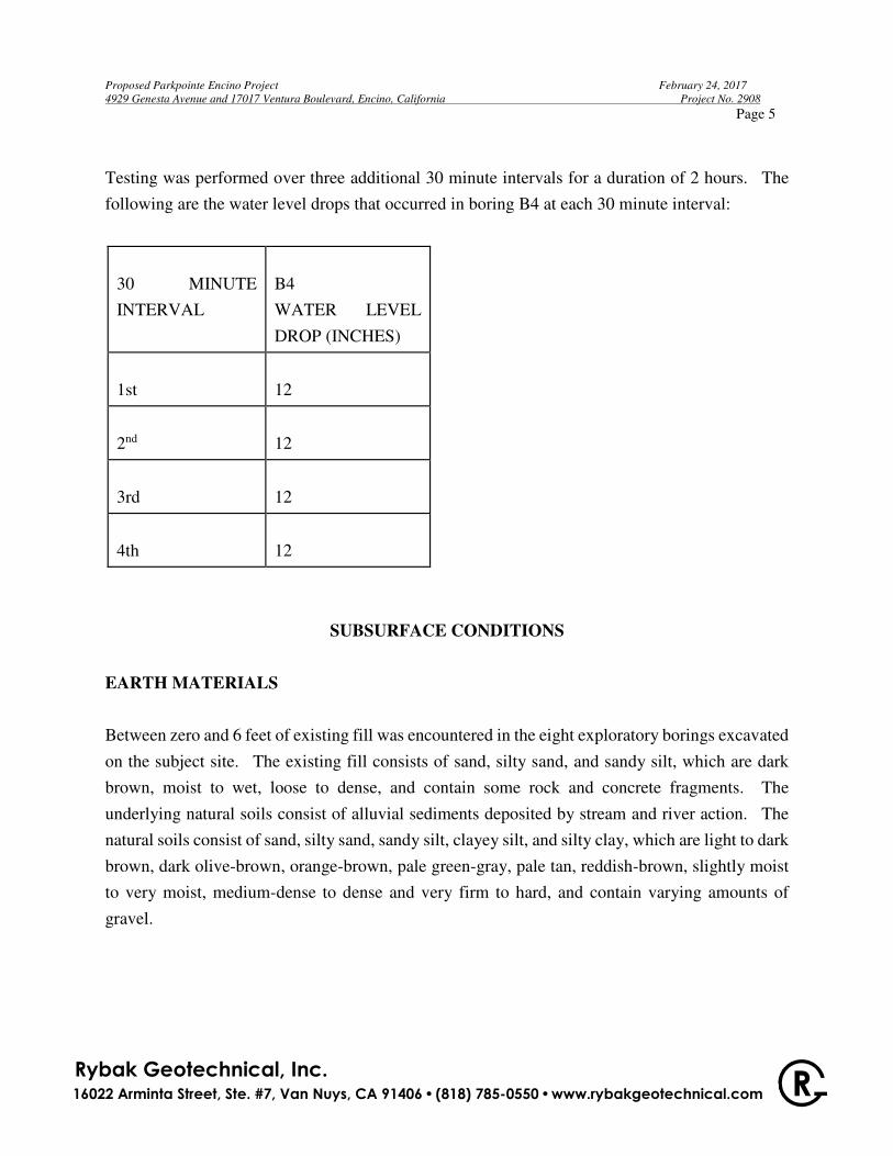
Testing was performed over three additional 30 minute intervals for a duration of 2 hours. The
following are the water level drops that occurred in boring B4 at each 30 minute interval:
30 MINUTE
INTERVAL
B4
WATER LEVEL
DROP (INCHES)
1st
12
2nd
12
3rd
12
4th
12
SUBSURFACE CONDITIONS
EARTH MATERIALS
Between zero and 6 feet of existing fill was encountered in the eight exploratory borings excavated
on the subject site. The existing fill consists of sand, silty sand, and sandy silt, which are dark
brown, moist to wet, loose to dense, and contain some rock and concrete fragments. The
underlying natural soils consist of alluvial sediments deposited by stream and river action. The
natural soils consist of sand, silty sand, sandy silt, clayey silt, and silty clay, which are light to dark
brown, dark olive-brown, orange-brown, pale green-gray, pale tan, reddish-brown, slightly moist
to very moist, medium-dense to dense and very firm to hard, and contain varying amounts of
gravel.

R Rybak Geotechnical, Inc. 16022 Arminta Street, Ste. #7, Van Nuys, CA 91406 · (818) 785-0550 · www.rybakgeotechnical.com
Proposed Parkpointe Encino Project February 24, 2017
4929 Genesta Avenue and 17017 Ventura Boulevard, Encino, California Project No. 2908
Page 6
GROUNDWATER
No groundwater was encountered during our exploration to the total depth of 66.5 feet. As part
of this investigation, the referenced document entitled Seismic Hazard Evaluation of the Canoga
Park 7.5-Minute Quadrangle, Los Angeles County, California was reviewed. Plate 1.2 from this
document shows the historically highest ground water contours for this quadrangle, with the
contours representing the depth to ground water in feet. According to Plate 1.2, the historically
highest groundwater level in the immediate area of the subject project was at a depth of 30 feet
below surface grade. Fluctuations in the level of groundwater may occur due to variations in
rainfall, temperature, and other factors not evident at the time of the measurements reported herein.
Fluctuations also may occur across the site. High groundwater levels can result in changed
conditions.
FAULTING AND SEISMICITY CONSIDERATIONS
GENERAL
Based on criteria established by the California Geological Survey (CGS), faults may be
categorized as active, potentially active or inactive. Active faults are those which show evidence
of surface displacement within the last 11,000 years (Holocene-age). Potentially-active faults are
those that show evidence of last displacement within the last 1.6 million years (Quaternary-age).
Faults showing no evidence of displacement within the last 1.6 million years may be considered
inactive for most purposes, except for some critical structures.
In 1972, the Alquist-Priolo Special Studies Zones Act (now known as the Alquist-Priolo
Earthquake Fault Zoning Act) was passed into law. The Act defines "active" and "potentially
active" faults utilizing the same aging criteria as that used by the CGS, above. However, the
established policy is to zone only those potentially active faults that have a relatively high potential
for ground rupture. Therefore, not all faults termed "potentially active" by the CGS are zoned
under the Alquist-Priolo Act. The subject site is not located within any of the state’s Alquist-
Priolo Earthquake Fault Zones. In addition, no known, mapped active or potentially active faults
traverse through the site.

R Rybak Geotechnical, Inc. 16022 Arminta Street, Ste. #7, Van Nuys, CA 91406 · (818) 785-0550 · www.rybakgeotechnical.com
Proposed Parkpointe Encino Project February 24, 2017
4929 Genesta Avenue and 17017 Ventura Boulevard, Encino, California Project No. 2908
Page 7
Seismic sources other than faults with known surface expression are so-called “buried thrust
faults”. These faults are not exposed at the surface and are typically broadly defined based on the
analysis of seismic wave recordings of several hundreds of small earthquakes in the southern
California area.
Two major buried thrust faults in the Los Angeles area are the Elysian Park fold and thrust belt
and the Torrance-Wilmington fold and thrust belt. It is postulated that the Elysian Park structure
was responsible for the magnitude 5.9, October 1, 1987 Whittier Narrows earthquake. It is
postulated that the Torrance-Wilmington structure was responsible for the magnitude 5.0, January
19, 1989 Malibu earthquake. It is believed that the magnitude 6.7, January 17, 1994 Northridge
earthquake was caused by a blind section of the Oak Ridge system located beneath the San
Fernando Valley.
Due to the buried nature of these thrust faults, their existence is usually not known until they
produce an earthquake. The risk for surface rupture potential of these buried thrust faults is
inferred to be low. However, the seismic risk of these buried structures in terms of recurrence
and maximum potential magnitude, is not yet well established. Therefore, the potential for
surface rupture on these surface-verging splays at magnitudes higher than 6.0 cannot be totally
precluded.
SITE SEISMICITY
Being located in southern California, the subject site has been subject to ground shaking in the past
on numerous occasions. The site, as all of the southern California area, is located in a seismically
active region and will experience slight to intense ground shaking as the result of movement along
various active faults in the region.
LIQUEFACTION EVALUATION
Liquefaction is a phenomena which involves the transformation of a granular material from a solid
state into a liquid state as a result of increased pore-water pressures. Increase in pore-water

R Rybak Geotechnical, Inc. 16022 Arminta Street, Ste. #7, Van Nuys, CA 91406 · (818) 785-0550 · www.rybakgeotechnical.com
Proposed Parkpointe Encino Project February 24, 2017
4929 Genesta Avenue and 17017 Ventura Boulevard, Encino, California Project No. 2908
Page 8
pressures due to earthquake shaking is one cause of liquefaction. Liquefaction is most likely to
occur in poorly consolidated, saturated fine-grained sands. The potential for liquefaction
occurring in a soil deposit increases as the depth to groundwater decreases, the ground acceleration
and duration of shaking increases, the relative density of the saturated soils decreases, and the
amount of fines decreases. Complete liquefaction of a soil mass involves the near-total loss of
soil strength. This typically occurs when the responsible earthquake is of such magnitude and
duration that the pore water pressures are allowed to increase to the point where the effective grain-
to-grain soil strength is completely diminished. However, the term “liquefaction” is also
commonly utilized to describe the mechanism which results in limited deformation of the
underlying soils. In this case, the pore-water pressures do not increase enough for the soil to lose
all its strength, but only enough so that the soils undergo limited mobility.
The evaluation of liquefaction potential requires that the values of PGA and PGAM be determined.
PGA is the peak ground acceleration due to the Maximum Considered Earthquake – Geometric
Mean (MCEG). Once the PGA is determined, PGAM can be determined by multiplying PGA by
a site coefficient, FPGA. Based on the USGS Design Maps Detailed Report, the PGA for the
subject site is 0.715. Based on a FPGA value of 1.0, the value of PGAM is determined to be 0.715.
A historic high depth to groundwater of 30 feet was used in the analyses. The liquefaction potential
evaluation for the subject site was performed utilizing the computer program LIQUEFY2 (Blake,
1998). The results of the evaluation are included in the Appendix.
The liquefaction potential evaluation is performed for two different peak ground accelerations.
For purposes of determining the settlement limits for the use of different foundation systems, a
peak ground acceleration value equal to two-thirds of the PGAM, or 0.48 g, will be utilized. The
earthquake magnitude used in this evaluation was determined by deaggregation of the seismic
source parameters utilizing the USGS 2008 Interactive Deaggregation web site. A 10%
probability of exceedance in 50 years (475-year return period) was used. Alluvium conditions
are assumed. The results of the deaggregation indicate an earthquake magnitude (MW) of 6.61.
The results of the enclosed liquefaction analyses indicate that the soils are not prone to liquefaction.
For purposes of preventing liquefaction-induced structure collapse, a peak ground acceleration
value equal to PGAM, or 0.715 g, was utilized. The earthquake magnitude used in this evaluation

R Rybak Geotechnical, Inc. 16022 Arminta Street, Ste. #7, Van Nuys, CA 91406 · (818) 785-0550 · www.rybakgeotechnical.com
Proposed Parkpointe Encino Project February 24, 2017
4929 Genesta Avenue and 17017 Ventura Boulevard, Encino, California Project No. 2908
Page 9
was 6.61, determined from the aforementioned USGS website and utilizing a 2% probability of
exceedance in 50 years (2,475-year return period). The results of the enclosed liquefaction
analyses indicate that the soils are not prone to liquefaction.
The following correction factors were utilized in the evaluation:
- Borehole diameter correction factor of 1.00.
- Sampler size correction factor of 1.20, since liners not used in sampler.
- N60 hammer correction factor of 1.30, since automatic-trip hammer used in sampling.
SEISMIC HAZARDS
FAULT RUPTURE
The results of geologic literature research indicate that the subject site is not underlain by any
known, mapped active or potentially active fault deemed capable of rupturing the surface. The
site is not located within any Alquist-Priolo Earthquake Fault Zone. The potential for fault
rupture on this site is considered remote.
LANDSLIDING
The subject site is not located within a potential earthquake-induced landslide zone per the Seismic
Hazard Evaluation of the Canoga Park 7.5-Minute Quadrangle, Los Angeles County, California.
DYNAMIC SETTLEMENTS
Seismically-induced settlement or compaction of dry or moist, cohesionless soils can also be a
secondary effect of earthquake ground motion. Such settlements are typically most damaging
when the settlements are differential in nature across the length of structures. Some seismically-
induced settlement of the proposed structure should be expected as a result of strong ground
shaking, however, due to the relatively dense and uniform nature of the soils, excessive differential
settlements are not anticipated on this site.

R Rybak Geotechnical, Inc. 16022 Arminta Street, Ste. #7, Van Nuys, CA 91406 · (818) 785-0550 · www.rybakgeotechnical.com
Proposed Parkpointe Encino Project February 24, 2017
4929 Genesta Avenue and 17017 Ventura Boulevard, Encino, California Project No. 2908
Page 10
CONCLUSIONS AND RECOMMENDATIONS
GENERAL
Development of the site is considered feasible from a geotechnical engineering standpoint,
provided the following recommendations are implemented during design and construction. The
design of the proposed project is still preliminary. This office should be kept informed of all
design revisions so that the recommendations contained herein can be appropriately revised, if
necessary.
Between zero and 3.5 feet of existing fill was encountered in borings B-1 through B-6. Borings
B-7 and B-8 were excavated with hand-auger equipment within a relatively narrow planter located
between the existing building and the sidewalk off of Ventura Boulevard. Boring B-7 was
excavated to refusal on a cobble at 6 feet, while boring B-8 was excavated to refusal on concrete
(footing?) at 1-1/2 feet. The existing fill was not penetrated in borings B-7 and B-8. Deeper fill
may exist in other areas of the site that were not directly explored. Excavation for the proposed
residential building subterranean parking levels is anticipated to penetrate through the existing fill
and expose competent natural soils throughout the excavation bottom. The existing fill is not
considered suitable for support of foundations, concrete flatwork, or additional structural fill. The
existing fill will need to be removed and recompacted beneath the proposed at-grade
commercial/retail building located south of the existing alley.
The proposed buildings may be supported on shallow, conventional spread footings embedded in
either competent natural soils or properly compacted fill which has been placed atop competent,
approved natural soils. All floor slabs should be supported on either competent natural soils or
properly compacted fill which has been placed atop competent, approved natural soils.
Groundwater was not encountered during our exploration to the total depth of 66.5 feet.
Excavation for the proposed subterranean parking levels is anticipated to extend to depths of
approximately 17 feet below ground surface, including foundation construction. Based upon
conditions encountered at the time of exploration, groundwater is not anticipated to be an issue
R Rybak Geotechnical, Inc. 16022 Arminta Street, Ste. #7, Van Nuys, CA 91406 · (818) 785-0550 · www.rybakgeotechnical.com
Proposed Parkpointe Encino Project February 24, 2017
4929 Genesta Avenue and 17017 Ventura Boulevard, Encino, California Project No. 2908
Page 11
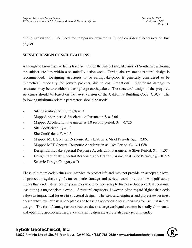
during excavation. The need for temporary dewatering is not considered necessary on this
project.
SEISMIC DESIGN CONSIDERATIONS
Although no known active faults traverse through the subject site, like most of Southern California,
the subject site lies within a seismically active area. Earthquake resistant structural design is
recommended. Designing structures to be earthquake-proof is generally considered to be
impractical, especially for private projects, due to cost limitations. Significant damage to
structures may be unavoidable during large earthquakes. The structural design of the proposed
structures should be based on the latest version of the California Building Code (CBC). The
following minimum seismic parameters should be used:
- Site Classification = Site Class D
- Mapped, short period Acceleration Parameter, Ss = 2.061
- Mapped Acceleration Parameter at 1.0 second period, S1 = 0.725
- Site Coefficient, Fa = 1.0
- Site Coefficient, Fv = 1.5
- Mapped MCE Spectral Response Acceleration at Short Periods, Sms = 2.061
- Mapped MCE Spectral Response Acceleration at 1 sec Period, Sm1 = 1.088
- Design Earthquake Spectral Response Acceleration Parameter at Short Period, Sds = 1.374
- Design Earthquake Spectral Response Acceleration Parameter at 1-sec Period, Sd1 = 0.725
- Seismic Design Category = D
These minimum code values are intended to protect life and may not provide an acceptable level
of protection against significant cosmetic damage and serious economic loss. A significantly
higher than code lateral design parameter would be necessary to further reduce potential economic
loss during a major seismic event. Structural engineers, however, often regard higher than code
values as impractical for use in structural design. The structural engineer and project owner must
decide what level of risk is acceptable and to assign appropriate seismic values for use in structural
design. The risk of damage to the structure due to a large earthquake cannot be totally eliminated,
and obtaining appropriate insurance as a mitigation measure is strongly recommended.
R Rybak Geotechnical, Inc. 16022 Arminta Street, Ste. #7, Van Nuys, CA 91406 · (818) 785-0550 · www.rybakgeotechnical.com
Proposed Parkpointe Encino Project February 24, 2017
4929 Genesta Avenue and 17017 Ventura Boulevard, Encino, California Project No. 2908
Page 12
INFILTRATION FACILITY
The field-measured percolation rate needs to be reduced to accommodate both suitability
assessment related considerations and design related considerations. The calculation worksheet
is enclosed with this report. The combined safety factor calculated is 2.6. Prior to adjusting the
field percolation rate by the aforementioned suitability assessment and design considerations, a
County of Los Angeles reduction factor was applied to account for exfiltration occurring through
the sides of the boring. The calculated design percolation rate is 0.3 inches per hour. This is less
than the minimum allowable percolation rate of 0.5 inches. Therefore, percolation of water into
the subsurface is not recommended. The use of above-ground sealed planters should be
considered.
CONVENTIONAL FOUNDATIONS
Design – Proposed Residential Building
The foundations at the level of the lowest subterranean garage may consist of conventional spread
footings embedded in the underlying natural alluvial soils. The footings should be embedded a
minimum of 24 inches below lowest adjacent grade, and be embedded a minimum of 18 inches
into the competent natural soils. Footings may need to be deepened if observations during
construction indicate unsatisfactory soil conditions.
Continuous wall footings may be designed for an allowable bearing value of 4,000 pounds per
square foot, and should be a minimum of 12 inches in width. Column footings may be designed
for an allowable bearing value of 4,500 pounds per square foot, and should be a minimum of 24
inches in width.
A one-third increase in the above allowable bearing values may be utilized for wind or seismic
loads. The recommended bearing values are net values, and the weight of the concrete in the
footings may be taken as 50 pounds per cubic foot, and the weight of the soil backfill may be
neglected when determining the downward loads.

R Rybak Geotechnical, Inc. 16022 Arminta Street, Ste. #7, Van Nuys, CA 91406 · (818) 785-0550 · www.rybakgeotechnical.com
Proposed Parkpointe Encino Project February 24, 2017
4929 Genesta Avenue and 17017 Ventura Boulevard, Encino, California Project No. 2908
Page 13
All conventional, continuous wall footings should be reinforced with a minimum of four, #4 steel
bars, two near the top and two near the bottom of the footings.
Design – Proposed Commercial/Retail Building
Conventional spread footings embedded in the underlying natural soils or on properly compacted
fill which has been placed on competent, approved natural soils can be used for foundation support
of the proposed at-grade commercial/retail building. The footings should be embedded a
minimum of 24 inches below lowest adjacent grade, and be embedded a minimum of 18 inches
into the competent natural soils or properly compacted fill. Footings may need to be deepened if
observations during construction indicate unsatisfactory soil conditions.
Continuous wall footings may be designed for an allowable bearing value of 2,000 pounds per
square foot, and should be a minimum of 12 inches in width. Column footings may be designed
for an allowable bearing value of 2,500 pounds per square foot, and should be a minimum of 24
inches in width.
A one-third increase in the above allowable bearing values may be utilized for wind or seismic
loads. The recommended bearing values are net values, and the weight of the concrete in the
footings may be taken as 50 pounds per cubic foot, and the weight of the soil backfill may be
neglected when determining the downward loads.
All conventional, continuous wall footings should be reinforced with a minimum of four, #4 steel
bars, two near the top and two near the bottom of the footings.
Resistance to Lateral Loading
Resistance to lateral loading may be provided by soil friction and by the passive resistance of the
natural soils or properly compacted fill. An allowable coefficient of friction of 0.4 may be used
between footings and the supporting soils. An allowable passive resistance of the natural soils or
properly compacted fill against footings may be assumed to be 300 pounds per cubic foot, to a
maximum of 3,000 pounds per square foot. The passive resistance of the soils and the frictional
R Rybak Geotechnical, Inc. 16022 Arminta Street, Ste. #7, Van Nuys, CA 91406 · (818) 785-0550 · www.rybakgeotechnical.com
Proposed Parkpointe Encino Project February 24, 2017
4929 Genesta Avenue and 17017 Ventura Boulevard, Encino, California Project No. 2908
Page 14
resistance between the footings and the supporting soils may be combined without reduction in
determining the total lateral resistance.
Settlement
A majority of the settlement of the new foundations is expected to occur upon initial loading. The
settlement of the new foundations is not expected to exceed 1/2 inch. Differential settlements
between adjacent columns is not expected to exceed 1/4 inch.
Installation
To provide proper foundation support, new footings should not surcharge any materials other than
properly controlled fill or undisturbed, competent natural soils. Proper footing depth may be
determined by extending an imaginary 1:1 plane downward from the bottom edges of the new
footings. Proper footing depth is achieved when all of the following conditions are met:
� The bottom of footing is embedded the recommended depth below lowest adjacent grade
and into the recommended bearing material.
� The imaginary plane is below any unsuitable soils or existing structures and only properly
controlled fill or undisturbed natural soils are intersected by the extended plane.
All footing excavations should be cleaned of loose soil and debris and inspected and approved by
the geotechnical engineer prior to the placement of reinforcing steel, concrete forms, or concrete.
The geotechnical engineer should verify that the footing will penetrate into the recommended
bearing material. Any required footing backfill should be mechanically compacted; flooding or
jetting with water is not permitted.
FLOOR SLABS
Concrete floor slabs-on-grade which will not be impacted by vehicular traffic should be a
minimum of 4 inches in thickness. Floor slabs which will be impacted by vehicular traffic should
be a minimum of 5 inches in thickness. All floor slabs should be supported on undisturbed natural

R Rybak Geotechnical, Inc. 16022 Arminta Street, Ste. #7, Van Nuys, CA 91406 · (818) 785-0550 · www.rybakgeotechnical.com
Proposed Parkpointe Encino Project February 24, 2017
4929 Genesta Avenue and 17017 Ventura Boulevard, Encino, California Project No. 2908
Page 15
soils or on properly compacted fill. All floor slabs should be reinforced with a minimum of #4
steel bars placed 16 inches on center, each way. In order to decrease the potential for moisture to
migrate through the floor slab, it is recommended that a fiber reinforcement additive be added to
the concrete mix. This will improve the tensile strength of the concrete and reduce the likelihood
of shrinkage cracks from developing. In addition, it is important that any shrinkage cracks that
do develop in the floor slab be sealed prior to covering of the slab.
Floor slabs that would be critically affected by moisture, should be underlain by a vapor retardant
which consists of a minimum 15-mil thick extruded polyolefin plastic (no recycled content or
woven materials permitted). Permeance as tested before and after mandatory conditioning should
be less than 0.01 perms and comply with the ASTM E1745 Class A requirements. Vapor
retardant should be installed according to ASTM E1643, including proper perimeter seal. The
concrete should be poured directly atop the vapor retardant. No sand should be placed atop the
vapor retardant. The concrete mix should be designed so as to minimize possible curling of the
slab. The concrete slabs should be allowed to cure properly before placing vinyl or other
moisture-sensitive floor covering. Prior to placement of the vapor retardant or casting of concrete
against soil, the soil subgrade should be wetted to eliminate any shrinkage cracks.
Construction activities and exposure to the environment can cause deterioration of prepared
subgrades. Therefore, we recommend that our field representative observe the condition of the
final subgrade earth materials immediately prior to slab-on-grade construction and, if necessary,
perform further field density and moisture content tests to determine the suitability of the final
prepared subgrade.
Concrete shrinks as it cures, resulting in shrinkage tension within the concrete mass. The
development of tension results in cracks within the concrete since concrete is weak in tension.
Therefore, the concrete should be placed using procedures to minimize the cracking within the
slab. Shrinkage cracks can become excessive if water is added to the concrete above the allowable
limit and proper finishing and curing practices are not followed. Concrete mixing, placement,
finishing and curing should be performed per the American Concrete Institute Guide for Concrete
Floor and Slab Construction (ACI 301.1R-89). Where shrinkage cracks would be

R Rybak Geotechnical, Inc. 16022 Arminta Street, Ste. #7, Van Nuys, CA 91406 · (818) 785-0550 · www.rybakgeotechnical.com
Proposed Parkpointe Encino Project February 24, 2017
4929 Genesta Avenue and 17017 Ventura Boulevard, Encino, California Project No. 2908
Page 16
unsightly, such as in the garage, concrete slabs on grade should be provided with tooled, crack
control joints at 10 to 15-foot centers or as specified by the structural engineer.
Tile flooring can crack, reflecting cracks in the concrete slab below the tile. Therefore, the slab
designer should consider additional steel reinforcement in concrete slabs on-grade that will directly
support tile. The tile installer should consider installation methods that reduce possible cracking
of the tile. A vinyl crack isolation membrane (approved by the Tile Council of America/Ceramic
Tile Institute) is recommended between tile and concrete slabs-on-grade per the Portland Cement
Association Specifications.
RETAINING WALLS
Restrained Design
It is anticipated that the subterranean parking basement retaining walls will be designed for a
restrained condition (i.e. no movement allowed at the top of wall). These retaining walls are
anticipated to be up to 15 feet in height. Retaining walls that will be properly drained, preventing
the buildup of hydrostatic pressure, may be designed for an at-rest equivalent fluid pressure of 69
pounds per cubic foot.
Additional pressure should be added for a surcharge condition due to adjacent structures or
vehicular traffic. For the purposes of this report, a retaining wall is considered “surcharged” when
an imaginary plane projected upwards from the bottom of the back of the retaining wall at an angle
of 45 degrees projects below vehicular traffic or existing structures/foundations. In addition to the
recommended earth pressure, the upper ten feet of the basement walls adjacent to vehicular traffic
should be designed to resist a uniform lateral pressure of 100 pounds per square foot, acting as a
result of an assumed 300 pounds per square foot surcharge behind the walls due to traffic. If the
traffic is kept back at least ten feet from the basement walls, the traffic surcharge may be neglected.

R Rybak Geotechnical, Inc. 16022 Arminta Street, Ste. #7, Van Nuys, CA 91406 · (818) 785-0550 · www.rybakgeotechnical.com
Proposed Parkpointe Encino Project February 24, 2017
4929 Genesta Avenue and 17017 Ventura Boulevard, Encino, California Project No. 2908
Page 17
Seismic Loading on Retaining Walls
For retaining walls in excess of 6 feet in height, additional lateral seismic loading should be applied
due to earthquake motions. This is according to the 2013 CBC. Using the Mononobe-Okabe
method, and with a PGAM value of 0.715, and assuming a kh = (1/2)(2/3)(PGAM), or 0.24, a thrust
of 11.7 (H)2 pounds per one foot length of retaining wall should be applied at a point located 0.6(H)
above the base of the retaining wall footing, where H is the height of the retaining wall in feet.
For free-standing retaining walls, this seismic thrust should be added to the static active earth
pressure. For retaining walls which are considered restrained from movement at the top and are
designed for the recommended static, at-rest earth pressures, no additional seismic loading need
be applied.
Free-Standing Design
Drained retaining walls which are considered free-standing and not restrained from movement at
the top, may be designed for a minimum equivalent fluid pressure 35 pounds per cubic foot.
Additional pressure should be added for a surcharge condition due to sloping backslope, vehicular
traffic or adjacent structures. This equivalent fluid pressure may be utilized provided the retaining
walls are provided with proper subsurface and surface drainage, as recommended within this
report.
Wall Drainage
Drained retaining walls should be provided with a drainage system extended at least two-thirds the
height of the wall. At the base of the drain system, a subdrain covered with a minimum of 12
inches of gravel should be installed, and a compacted fill blanket or other seal placed at the surface.
The clean bottom and subdrain pipe, behind the retaining wall, should be observed by a
representative of this office, prior to placement of gravel or compacting backfill.
Alternatively, a plastic drainage composite such as Miradrain or equivalent may be installed in
continuous, 4-foot wide columns along the entire back face of the wall, at 8 feet on center. The
top of these drainage composite columns should terminate approximately 18 inches below the

R Rybak Geotechnical, Inc. 16022 Arminta Street, Ste. #7, Van Nuys, CA 91406 · (818) 785-0550 · www.rybakgeotechnical.com
Proposed Parkpointe Encino Project February 24, 2017
4929 Genesta Avenue and 17017 Ventura Boulevard, Encino, California Project No. 2908
Page 18
ground surface, where either hardscape of a minimum of 18 inches of relatively cohesive material
should be placed as a cap. These vertical columns of drainage material would then be connected
at the bottom of the wall to a collection panel or a one-cubic foot rock pocket drained by 4-inch
subdrain pipe. Subdrainage pipes at the base of the retaining wall drainage system should outlet
to an acceptable location via controlled drainage structures.
Waterproofing of the subterranean walls is recommended. The design and inspection of the
waterproofing is not the responsibility of the geotechnical engineer. A waterproofing consultant
should be retained in order to recommend a product or method which would provide protection to
subterranean walls, floor slabs, and foundations.
Wall Backfill
Wall backfill should be mechanically compacted in loose layers not more than 8 inches in
thickness, to the proper relative compaction. Flooding or jetting of the backfill is not permitted.
Proper compaction of the backfill will be necessary to reduce settlements of the backfill and
overlying flatwork.
Prior to backfilling, the excavation between retaining walls and the temporary excavations should
be cleared of all loose materials, debris, construction materials, etc. The backfill should be free
of rocks larger than 6 inches in any dimension. Proper compaction of the backfill will be
necessary to reduce the potential settlement of the backfill. Some settlement of the backfill should
be anticipated and any utilities and flatwork supported therein should be designed to accept
differential settlement, particularly at the points of entry to the structures. Retaining wall backfill
should be properly compacted, as recommended in the “Site Grading” section of this report.
Compaction testing of the wall backfill every 2 vertical feet will be necessary during fill placement
to verify percentage of compaction achieved during fill placement. The retaining wall backfill
may be capped with proper surface drainage gutters to collect and transfer collected drainage to an
appropriate location.
R Rybak Geotechnical, Inc. 16022 Arminta Street, Ste. #7, Van Nuys, CA 91406 · (818) 785-0550 · www.rybakgeotechnical.com
Proposed Parkpointe Encino Project February 24, 2017
4929 Genesta Avenue and 17017 Ventura Boulevard, Encino, California Project No. 2908
Page 19
All retaining wall backfill should be placed in loose horizontal lifts not more than 8 inches in
thickness, watered as necessary to achieve the proper moisture content, and mechanically
compacted to at least 90 percent relative compaction. Flooding or jetting of the backfill is not
permitted. Probing and testing should be performed by the project geotechnical engineer to verify
proper compaction.
Where space limitations do not allow for conventional backfill compaction operations, the space
should be backfilled with pea gravel. The pea gravel should be placed in lifts of no more than 2
feet in thickness and should be compacted with vibratory equipment. Ideally, the top two feet of
backfill exposed to water infiltration should consist of compacted fill so that a relatively
impervious condition is developed. Filter fabric should be placed atop the pea gravel prior to
placement of the compacted fill.
Contractors should be informed that the use of heavy compaction equipment within close
proximity to retaining walls could cause excessive wall movement and/or earth pressures in excess
of design values.
The following observations should be performed by representatives of this firm during installation
of subdrains, placement of wall backfill, and placement of any other backfill:
� Observe the area behind the walls prior to placement of gravel for drain support and
subsequent to drain installation and prior to gravel backfilling.
� Perform visual observations to evaluate the suitability of on-site and import soils for
backfill placement; collect and submit fill samples for required or recommended laboratory
testing, where necessary.
� Perform field density and compaction testing to determine the percentage of compaction
achieved during fill placement.
The governmental agencies having jurisdiction over the project should be notified prior to
commencement of grading so that the necessary grading permits may be obtained and
arrangements may be made for the required inspections.

R Rybak Geotechnical, Inc. 16022 Arminta Street, Ste. #7, Van Nuys, CA 91406 · (818) 785-0550 · www.rybakgeotechnical.com
Proposed Parkpointe Encino Project February 24, 2017
4929 Genesta Avenue and 17017 Ventura Boulevard, Encino, California Project No. 2908
Page 20
SITE GRADING
Site Preparation and Compaction
It is anticipated that site grading for the proposed residential construction located north of the alley
will include excavation of site soils for the proposed subterranean structure, foundations, and
utility trenches, as well as placement of backfill for walls and trenches. For the proposed
commercial/retail construction located south of the alley, it is anticipated that site grading will
include removal and recompaction of existing unsuitable site soils for support of footings and floor
slabs. All new fill should be placed on either undisturbed natural soils or compacted fill
previously certified by a soils testing agency. All unsuitable deposits, such as any existing
uncertified fill, disturbed natural soils, vegetation, and debris, should either be penetrated or
removed and replaced by properly compacted fill soils for support of footings and concrete
flatwork and additional fill. After excavating as required, the exposed subgrade soils should be
carefully inspected by the geotechnical engineer or his representative to verify the removal of all
unsuitable deposits. Subsequently, the exposed soils should be scarified to a depth of 6 inches,
brought to near optimum moisture content, and compacted to a minimum of 90 percent of
maximum dry density obtainable by the ASTM Designation D1557 method of compaction.
After compacting the exposed soils, all required fill should be placed in loose lifts not more than
8 inches in thickness, brought to near optimum moisture content, and properly compacted.
Very moist to wet soils were encountered in the area of the proposed commercial/retail building.
The contractor should anticipate that soils to be replaced as compacted fill may require drying back
to close to optimum moisture content. Alternatively, wet soils may be removed from the site and
drier soils imported. Also, prior to placement of new fill on high moisture content soils, approved
bottom stabilization techniques will be necessary.

R Rybak Geotechnical, Inc. 16022 Arminta Street, Ste. #7, Van Nuys, CA 91406 · (818) 785-0550 · www.rybakgeotechnical.com
Proposed Parkpointe Encino Project February 24, 2017
4929 Genesta Avenue and 17017 Ventura Boulevard, Encino, California Project No. 2908
Page 21
Excavation Characteristics
The exploratory borings were excavated with the aid of a truck-mounted, hollow-stem auger
drilling rig and hand-auger equipment. It is expected that conventional grading equipment can be
utilized during construction.
Material for Fill
The on-site soils, less any debris or organic matter, may be used in compacted fills. Any required
imported fill should be inspected by the geotechnical engineer prior to stockpiling onsite.
Imported soils should consist of relatively granular soils with an Expansion Index of less than 20,
and be free of vegetation, debris, and deleterious materials. Fill should be free of rocks larger
than 6 inches in any dimension.
Utility Trench Backfill
Utility trenches should be properly backfilled in accordance with the requirements of the Green
Book (latest edition). The pipe should be bedded with clean sands to a depth of at least 12 inches
above the top of pipe. The use of gravel is not acceptable unless used in conjunction with filter
fabric to prevent the gravel from having direct contact with the soil. The remainder of the trench
should be properly backfilled with the on-site soils and mechanically compacted in lifts to the
applicable minimum relative compaction. Jetting or flooding of backfill materials is not
permitted.
Cesspool Abandonment
Any old cesspools encountered on the site during construction should be properly abandoned
during grading operations. Cesspools should be completely cleaned out and filled to within 5 feet
plus the depth of the future footings with a minimum two-sack slurry mix. The upper portion
should be benched into the surrounding natural soils and the fill tested to the proper relative
compaction. The entire footing footprint plus 5 feet out from the footing should be underlain by
a uniform thickness of compacted fill.

R Rybak Geotechnical, Inc. 16022 Arminta Street, Ste. #7, Van Nuys, CA 91406 · (818) 785-0550 · www.rybakgeotechnical.com
Proposed Parkpointe Encino Project February 24, 2017
4929 Genesta Avenue and 17017 Ventura Boulevard, Encino, California Project No. 2908
Page 22
Field Observation
The compaction of all required fill should be observed and tested by a representative of this firm.
The observation and testing should include the following:
� Observe the exposed subgrade in areas to receive fill and in areas where excavation has
resulted in the desired finished subgrade, observe proofrolling, and delineate areas
requiring overexcavation.
� Perform visual observations to evaluate the suitability of on-site and import soils for fill
placement; collect and submit soil samples for required or recommended laboratory testing,
where necessary.
� Perform field density testing to determine the percentage of compaction achieved during
fill placement. Verify proper moisture content during grading.
The governmental agencies having jurisdiction over the project should be notified prior to
commencement of grading so that the necessary grading permits may be obtained and
arrangements may be made for the required inspections.
EXPANSIVE SOILS
The surficial soils are considered to be Low in expansion potential. Special considerations with
respect to expansive soils are not required.
TEMPORARY EXCAVATIONS
General
For the purposes of this report, a temporary excavation is considered “surcharged” when an
imaginary plane projected upwards from the bottom of the excavation at an angle of 45 degrees
projects below one of the following: 1) the public way, 2) a neighboring property, 3) vehicular
traffic, or 4) existing structures/foundations. It is anticipated that temporary excavations up to 17
feet in height may be required for excavation and construction of the proposed subterranean level.
R Rybak Geotechnical, Inc. 16022 Arminta Street, Ste. #7, Van Nuys, CA 91406 · (818) 785-0550 · www.rybakgeotechnical.com
Proposed Parkpointe Encino Project February 24, 2017
4929 Genesta Avenue and 17017 Ventura Boulevard, Encino, California Project No. 2908
Page 23
The temporary excavations are anticipated to expose existing fill and alluvial soils, which may be
subject to caving where granular soils are exposed. Vertical excavations up to 5 feet in height
may be attempted where not surcharged by adjacent traffic or structures. Vertical excavations
greater than 5 feet will require sloping and/or shoring measures in order to provide a stable
excavation. Where sufficient space is available, temporary unsurcharged excavations up to 12
feet high could be sloped back at a uniform 1:1 (H:V) slope gradient or flatter. A uniform slope
does not have a vertical portion. Where space is limited, shoring or slot cut measures will be
required. All surcharged temporary excavations should be shored or slot cut.
Where sloped embankments are utilized, the tops of the slopes should be barricaded to prevent
vehicles and storage loads within 5 feet of the tops of the slopes. If the temporary construction
embankments are to be maintained during the rainy season, berms are suggested along the tops of
the slopes where necessary to prevent runoff water from entering the excavation and eroding the
slope faces. All excavations should be stabilized within 30 days of initial excavation.
Slot Cuts
The following conditions are required for construction of slot cuts. Slot cuts are not allowed for
vertical excavations in excess of 12 feet high. It is recommended that slot cut procedures be
discussed at a pre-grading site meeting attended by at least the geotechnical engineer, the grading
contractor, and the City grading inspector. The initial slope is to be excavated under direct
observation provided by the geotechnical engineer or his representative. This initial cut is to be
formed at a gradient of 1:1 (horizontal:vertical). The first series of slot cuts should be laid out
along the temporary slope in a sequence identified as A-B-C, i.e. only the “A” slots would be
excavated and the intervening two slots (B and C) would remain as buttresses. The removal and
recompaction operations and/or footing excavations would be performed within the “A” slots.
Subsequently, the “B” slots would be worked. Finally, upon completion of work within the “B”
slots, the “C” slots would be excavated. The slots should be a maximum of 8 feet in width, and
the intervening buttresses should be 16 feet in width.

R Rybak Geotechnical, Inc. 16022 Arminta Street, Ste. #7, Van Nuys, CA 91406 · (818) 785-0550 · www.rybakgeotechnical.com
Proposed Parkpointe Encino Project February 24, 2017
4929 Genesta Avenue and 17017 Ventura Boulevard, Encino, California Project No. 2908
Page 24
Shoring
The following information on the design and installation of the shoring is preliminary. Review
of the final shoring plans and specifications should be made by this office prior to bidding or
negotiating with a shoring contractor.
A shoring system consisting of steel soldier beams is recommended for this project. The steel
soldier beams may be placed in drilled holes and backfilled with concrete, or may be installed
utilizing high frequency vibration. Where maximum excavation heights are less than 12 feet, the
soldier piles are typically designed as cantilevers. Where excavations exceed 12 feet, or are
surcharged, soldier piles may require lateral bracing utilizing drilled tie-back anchors to maintain
an economical steel beam size and prevent excessive lateral deflection. The size of the steel beam
and the acceptable shoring deflection should be determined by the project shoring engineer.
The design embedment of the shoring pile toes must be maintained during excavation activities.
The toes of the perimeter shoring piles should be deepened to take into account any required
excavations necessary for grading activities, foundations, and/or adjacent drainage systems.
Drilled, cast-in-place soldier piles should be placed no closer than 3 diameters on center. The
minimum diameter of the piles is 18 inches. Structural concrete should be used for the soldier
piles below the excavation; lean-mix concrete may be employed above that level. As an
alternative, lean-mix concrete may be used throughout the pile where the reinforcing consists of a
wide flange section. The slurry must be of sufficient strength to impart the lateral bearing pressure
developed by the wide flange section to the soil. For design purposes, an allowable passive value
for the soils below the bottom plane of excavation, may be assumed to be 500 pounds per square
foot per foot of depth, to a maximum of 5,000 pounds per square foot. To develop the full lateral
value, provisions should be implemented to assure firm contact between the soldier piles and the
undisturbed soils.
Casing may be required should caving be experienced in the granular soils. If casing is used,
extreme care should be employed so that the pile is not pulled apart as the casing is withdrawn.

R Rybak Geotechnical, Inc. 16022 Arminta Street, Ste. #7, Van Nuys, CA 91406 · (818) 785-0550 · www.rybakgeotechnical.com
Proposed Parkpointe Encino Project February 24, 2017
4929 Genesta Avenue and 17017 Ventura Boulevard, Encino, California Project No. 2908
Page 25
At no time should the distance between the surface of the concrete and the bottom of the casing be
less than 5 feet.
It is recommended that the exposed soils be observed by the soils engineer to verify the cohesive
nature of the soils and the areas where lagging may be omitted. Soldier piles should be designed
for the full anticipated pressures. Due to arching in the soils, the pressure on the lagging will be
less. It is recommended that the lagging be designed for the full design pressure but be limited to
a maximum of 400 pounds per square foot.
Cantilever soldier piles with a level back slope may be designed for a minimum equivalent fluid
pressure of 34 pounds per cubic foot. Additional pressure should be added for sloped conditions,
adjacent traffic, and structural surcharge conditions.
Tied-back or raker-braced shoring, with a level backslope, may be designed for a uniform
distribution of pressure of 20H pounds per square foot.
Because of the depth of the excavation, some means of monitoring the performance of the shoring
system is recommended. The monitoring should include ground surface settlement and lateral
deformation. Some movement of the shored embankments should be anticipated as a result of the
relatively deep excavation. The shoring should be designed for a lateral movement not to exceed
1/2 inch. It is recommended that photographs of the existing improvements on the adjacent
properties be made during construction to record any movements for use in the event of a dispute.
Tie-back Anchors
1. Design
Tie-back anchors may be used to resist lateral loads. Friction anchors are recommended. For
design purposes, it may be assumed that the active wedge adjacent to the shoring is defined by a
plane drawn 35 degrees with the vertical through the bottom plane of the excavation. Friction
anchors should extend a minimum of 20 feet beyond the potentially active wedge and to greater
lengths if necessary to develop the desired capacities. Only the frictional resistance developed

R Rybak Geotechnical, Inc. 16022 Arminta Street, Ste. #7, Van Nuys, CA 91406 · (818) 785-0550 · www.rybakgeotechnical.com
Proposed Parkpointe Encino Project February 24, 2017
4929 Genesta Avenue and 17017 Ventura Boulevard, Encino, California Project No. 2908
Page 26
beyond the imaginary plane would be effective in resisting lateral loads. The zone of earth
material located between the imaginary plane and the face of the excavation will be termed the
active wedge. The locations and depths of all offsite utilities should be thoroughly checked and
incorporated into the drilling angle design for the tie-back anchors.
The capacities of the anchors should be determined by testing of the initial anchors, as outlined in
a following section. Only the frictional resistance developed beyond the active wedge would be
effective in resisting lateral loads. Anchors should be placed at least 6 feet on center to be
considered isolated. For preliminary design purposes, it is estimated that drilled friction anchors
constructed without utilizing post-grouting techniques will develop average skin frictions as
follows: The design bond between gravity-filled tie-backs and the surrounding earth materials
may be estimated to be 30 Ha pounds per square foot (factor of safety of 2.0 already included in
the equation), where Ha is the depth of overburden, in feet, at the midpoint of the anchored portion
of the tiebacks. The maximum resistance using this equation should not exceed 900 pounds per
square foot. The design bond between pressure grout anchors and the surrounding earth materials
may be estimated as being 2,000 pounds per square foot. The above values should be used only
as a general guidance. The contractor must determine the appropriate value for bond based on
his experience and knowledge with similar projects in similar geologic conditions. The contractor
should be responsible for calculating the tie-back length since construction procedure will greatly
influence the bond between the earth materials and the grout. For example, caving will loosen the
earth materials and cause a significant reduction in the bond. In any event, the computed bond
length should be verified by a proof-test program performed under the observation of our
representative. Anchors should be placed at least 6 feet on center to be considered isolated.
The actual lengths of the anchors required may be longer than the lengths calculated using the
above average skin friction values. Pull-out testing of the anchors should be performed to verify
the actual length of anchors required.

R Rybak Geotechnical, Inc. 16022 Arminta Street, Ste. #7, Van Nuys, CA 91406 · (818) 785-0550 · www.rybakgeotechnical.com
Proposed Parkpointe Encino Project February 24, 2017
4929 Genesta Avenue and 17017 Ventura Boulevard, Encino, California Project No. 2908
Page 27
2. Anchor Installation
Tied-back anchors may be installed between 20 and 40 degrees below the horizontal; however,
occasionally alternative angles are necessary to avoid existing improvements and utilities. The
locations and depths of all offsite utilities should be thoroughly checked prior to design and
installation of the tie-back anchors. Anchor installation may be made difficult due to the presence
of sand and gravel deposits. Caving of the anchor shafts should be anticipated and provisions
should be implemented in order to minimize such caving. It is recommended that hollow-stem
auger drilling equipment be used to install the anchors. The anchor shafts should be filled with
concrete by pumping from the tip out, and the concrete should extend from the tip of the anchor to
the active wedge. In order to minimize the chances of caving, it is recommended that the portion
of the anchor shaft within the active wedge be backfilled with sand before testing the anchor. This
portion of the shaft should be filled tightly and flush with the face of the excavation. The sand
backfill should be placed by pumping; the sand may contain a small amount of cement to facilitate
pumping.
3. Anchor Testing
All of the anchors should be tested to at least 150 percent of design load. The total deflection
during this test should not exceed 12 inches. The rate of creep under the 150 percent test load
should not exceed 0.1 inch over a 15 minute period in order for the anchor to be approved for the
design loading.
At least ten percent of the anchors should be selected for "quick", 200 percent tests and three
additional anchors be selected for 24-hour, 200 percent tests. The purpose of the 200 percent tests
is to verify the friction value assumed in design. The anchors should be tested to develop twice
the assumed friction value. These tests should be performed prior to installation of additional tie-
backs. Where satisfactory tests are not achieved on the initial anchors, the anchor diameter and/or
length should be increased until satisfactory test results are obtained.

R Rybak Geotechnical, Inc. 16022 Arminta Street, Ste. #7, Van Nuys, CA 91406 · (818) 785-0550 · www.rybakgeotechnical.com
Proposed Parkpointe Encino Project February 24, 2017
4929 Genesta Avenue and 17017 Ventura Boulevard, Encino, California Project No. 2908
Page 28
The total deflection during the 24-hour 200 percent test should not exceed 12 inches. During the
24-hour tests, the anchor deflection should not exceed 0.75 inches measured after the 200 percent
test load is applied.
For the "quick" 200 percent tests, the 200 percent test load should be maintained for 30 minutes.
The total deflection of the anchor during the 200 percent quick tests should not exceed 12 inches;
the deflection after the 200 percent load has been applied should not exceed 0.25 inch during the
30-minute period.
After a satisfactory test, each anchor should be locked-off at the design load. This should be
verified by rechecking the load in the anchor. The load should be within 10 percent of the design
load. The installation and testing of the anchors should be observed by a representative of this
firm.
SITE SURFACE DRAINAGE
Proper surface drainage is critical to the future performance of the project. Uncontrolled
infiltration of irrigation excess and storm runoff into the soils can adversely affect the performance
of the planned improvements. Saturation of a soil can cause it to lose internal shear strength and
increase its compressibility, resulting in a change in the original designed engineering properties.
Proper drainage should be maintained at all times.
All site drainage should be collected and controlled in non-erosive drainage devices. Drainage
should not be allowed to pond anywhere on the site, and especially not against any foundation or
retaining wall. The site should be graded and maintained such that surface drainage is directed
away from structures in accordance with applicable standards. In addition, drainage should not
be allowed to flow uncontrolled over any descending slope. Discharge from downspouts, roof
drains and scuppers are not recommended onto unprotected soils within 5 feet of the building
perimeter. Planters which are located adjacent to foundations should be sealed to prevent
moisture intrusion into the soils providing foundation support. Landscape irrigation is not
recommended within 5 feet of the building perimeter footings except when enclosed in protected
planters.

R Rybak Geotechnical, Inc. 16022 Arminta Street, Ste. #7, Van Nuys, CA 91406 · (818) 785-0550 · www.rybakgeotechnical.com
Proposed Parkpointe Encino Project February 24, 2017
4929 Genesta Avenue and 17017 Ventura Boulevard, Encino, California Project No. 2908
Page 29
Positive surface gradients should be provided adjacent to all structures so as to direct surface water
run-off and roof drainage away from foundations and slabs toward suitable discharge facilities.
PLAN REVIEW
This report was prepared on the basis of exploration, laboratory testing, and analysis of the existing
site conditions. Formal plans ready for submittal to the Department of Building and Safety must
be reviewed by Rybak Geotechnical, Inc. prior to such submittal. Any change in the scope of the
project may require additional geotechnical work.
SITE OBSERVATION
It is recommended that all foundation excavations be observed by the geotechnical engineer’s
representative prior to placing forms, steel, or concrete. All excavations should be cleaned of
loose soil and debris prior to inspection. The excavations should be approved by this office prior
to the placement of reinforcing steel, concrete forms, or concrete. The geotechnical engineer
should verify that the footings will be embedded into the recommended bearing material. All
bottom excavations to receive compacted fill should be inspected by the geotechnical engineer
prior to placing any controlled compacted fill. Any fill that is placed must be approved, tested,
and verified if used for engineered purposes. Should the observations reveal any unforeseen
hazard, additional recommendations may be necessary.
Please advise Rybak Geotechnical, Inc. at least 24 hours prior to any required site visit. All
approved plans, permits, and geotechnical reports must be at the jobsite and available during
inspections.
CONSTRUCTION SITE MAINTENANCE
The construction contractor or general contractor shall supervise and direct the work and they shall
be solely responsible for all construction means, methods, techniques, sequences and procedures.
Also, they shall be solely and completely responsible for conditions on the job site, including safety
of all persons and property during the performance of work. Periodic or continuous observations

R Rybak Geotechnical, Inc. 16022 Arminta Street, Ste. #7, Van Nuys, CA 91406 · (818) 785-0550 · www.rybakgeotechnical.com
Proposed Parkpointe Encino Project February 24, 2017
4929 Genesta Avenue and 17017 Ventura Boulevard, Encino, California Project No. 2908
Page 30
by the geotechnical consultant will not, nor are intended to, include review of the adequacy of the
contractor’s safety measures in, on or near the construction site.
It is the responsibility of the contractor to maintain a safe construction site. When excavations
exist on a site, the area should be fenced and warning signs posted. Earth material generated by
foundation and subgrade excavations should be either removed from the site or properly placed as
a controlled compacted fill. Earth material must not be spilled over any descending slope.
Workers should not be allowed to enter any unshored trench excavations over 5 feet deep. All
shoring, bracing and excavation or confined space entry should be in accordance with current
requirements of CAL/OSHA, the Industrial Accident Commission of the State of California, and
all other public agencies having jurisdiction.
Please call this office with any questions. This report and the exploration are subject to the
following "Limitations" section. Please read the "Limitations" carefully, as it limits our liability.
LIMITATIONS
This report was prepared in accordance with generally accepted geotechnical engineering
principles and practice available at this time and with the degree of care and skill ordinarily
exercised under similar circumstances by geotechnical engineers practicing in this area. No other
representation, either expressed or implied, is made as to the conclusions and professional advice
included in this report.
This report was prepared exclusively for the sole use and benefit of the clients, Tristar Realty
Group, LLC, and their authorized agents, and is not transferrable. This report is intended for use
with regard to the specific project discussed herein. The conclusions and recommendations
contained in this report are based on the data relating only to the project and location discussed
herein. Any changes in design or locations of structures from those outlined in this report should
be provided to us so that we may review our conclusions and recommendations and make any
necessary modifications. The subsurface conditions described in this report have been projected
from borings on the site as indicated, and are believed representative of the project area.

Proposed Parkpointe Encino Project 4929 Genesta Avenue and 17017 Ventura Boulevard. Encino. California
February 24, 2017 Proiect No. 2908
Page 31
However, soil, geologic and groundwater conditions can vary significantly between exploratory
excavations and with passage of time. As with most projects, conditions revealed during
construction may be at variance with the findings herein. If this occurs, the changed conditions
must be evaluated by the geotechnical consultant, and additional recommendations provided, as
warranted.
The recommendations contained within this report were developed with the assumption that the
necessary geotechnical observations and testing will be performed during construction by a
representative of this firm. If construction phase services are performed by others, they must
accept full responsibility for all geotechnical aspects of the project, including this report.
RICHARD RYBAK G.E. 2131
Rybak Geotechnical, Inc. 16022 Arminta Street, Ste. #7, Van Nuys, CA 91406 • (818) 785-0550 • www.rybakgeotechnical.com

Rybak Geotechnical, Inc. R Consulting Engineers
Project: TRISTAR REALTY GROUP, LLC – 4929 Genesta Avenue and 17017 Ventura Blvd., Encino Project No: 2908 Date: February 24, 2017
Plate 1
Approximate Location of Boring
GEOTCHNICAL MAP
Parkpointe Encino
4929 Genesta Avenue and 17017 Ventura Blvd., Encino, CA
Approximate Scale 1”=50’
LEGEND:
B-8
NORTH
B-3
B-8 B-7
B-6
B-1 B-2
B-4
B-5 789.05
789.82
786.18781.56 781.37
781.95
783.10
784.96
786.34
788.22
785.03
785.40
781.95
Existing Spot Elevations
Proposed 4-Story Residential Buildingover 2 Levels of Parking
Proposed 1-Story Building
Approximate Proposed Finish Floor Elevation
769
769
774
771.5
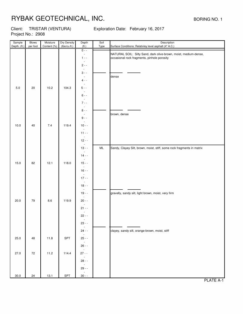
RYBAK GEOTECHNICAL, INC. BORING NO. 1
Sample Blows Moisture Dry Density Depth Soil Description
Depth, (ft.) per foot Content (%) (lbs/cu.ft.) (ft.) Type Surface Conditions: Relativley level asphalt (4" A.C.)
0 - -
- NATURAL SOIL: Silty Sand, dark olive-brown, moist, medium-dense,
1 - - occasional rock fragments, pinhole porosity
-
2 - -
-
3 - -
- dense
4 - -
-
5.0 20 10.2 104.3 5 - -
-
6 - -
-
7 - -
-
8 - -
- brown, dense
9 - -
-
10.0 40 7.4 119.4 10 - -
-
11 - -
-
12 - -
-
13 - - ML Sandy, Clayey Silt, brown, moist, stiff, some rock fragments in matrix
-
14 - -
-
15.0 82 12.1 118.0 15 - -
-
16 - -
-
17 - -
-
18 - -
-
19 - - gravelly, sandy silt, light brown, moist, very firm
-
20.0 79 8.6 119.9 20 - -
-
21 - -
-
22 - -
-
23 - -
-
24 - - clayey, sandy silt, orange-brown, moist, stiff
-
25.0 48 11.8 SPT 25 - -
-
26 - -
-
27.0 72 11.2 114.4 27 - -
-
28 - -
-
29 - -
-
30.0 24 13.1 SPT 30 - -
PLATE A-1
Project No.: 2908
Exploration Date: February 16, 2017Client: TRISTAR (VENTURA)

RYBAK GEOTECHNICAL, INC. BORING NO. 1 (Continued)
Sample Blows Moisture Dry Density Depth Soil Description
Depth, (ft.) per foot Content (%) (lbs/cu.ft.) (ft.) Type Surface Conditions:
30.0 24 13.1 SPT 30 - -
-
31 - -
-
32 - -
- SM Gravelly, Silty Sand, brown, slightly moist, dense
33 - -
-
34 - -
-
35.0 38 3.4 SPT 35 - -
-
36 - -
-
37 - - ML Sandy, Clayey Silt, pale green-gray, brown, orange-brown, moist, stiff
-
38 - -
-
39 - -
-
40.0 35 31.4 SPT 40 - -
-
41 - -
-
42 - -
-
43 - -
-
44 - -
-
45.0 30 30.6 SPT 45 - -
-
46 - -
-
47 - -
-
48 - -
- gray, orange-brown, stiff to hard, some rock fragments
49 - -
-
50.0 33 33.5 SPT 50 - -
-
51 - -
-
52 - -
-
53 - -
-
54 - -
-
55.0 47 48.6 SPT 55 - -
-
56 - -
-
57 - -
-
58 - -
-
59 - -
-
60.0 55 47.0 SPT 60 - -
PLATE A-2
Project No. 2908
Exploration Date: February 16, 2017Client: TRISTAR (VENTURA)

RYBAK GEOTECHNICAL, INC. BORING NO. 1 (Continued)
Sample Blows Moisture Dry Density Depth Soil Description
Depth, (ft.) per foot Content (%) (lbs/cu.ft.) (ft.) Type Surface Conditions:
60 - -
-
61 - -
-
62 - -
-
63 - -
-
64 - -
-
65.0 45 60.1 SPT 65 - -
-
66 - -
-
67 - -
-
68 - -
- Total depth: 66.5 feet
69 - - No groundwater
- No Fill
70 - -
-
71 - -
-
72 - -
-
73 - -
-
74 - -
-
75 - -
-
76 - -
-
77 - -
-
78 - -
-
79 - -
-
80 - -
-
81 - -
-
82 - -
-
83 - -
-
84 - -
-
85 - -
-
86 - -
-
87 - -
-
88 - -
-
89 - -
-
90 - -
PLATE A-3
Project No. 2908
Exploration Date: February 16, 2017Client: TRISTAR (VENTURA)

RYBAK GEOTECHNICAL, INC. BORING NO. 2
Sample Blows Moisture Dry Density Depth Soil Description
Depth, (ft.) per foot Content (%) (lbs/cu.ft.) (ft.) Type Surface Conditions: Relativley level asphalt (4" A.C.)
0 - -
- NATURAL SOIL: Sandy Silt, light brown, slightly moist, firm,
1 - - occasional rock fragments
-
2 - -
-
3 - -
-
4 - -
-
5.0 27 9.2 109.0 5 - -
-
6 - -
-
7 - -
-
8 - -
-
9 - -
-
10.0 85 for 10" 6.2 121.4 10 - -
-
11 - -
-
12 - -
- Sandy, Clayey Silt, brown, moist, stiff to hard, some rock fragments in matrix
13 - -
-
14 - -
-
15.0 50 for 5" 11.3 115.6 15 - -
-
16 - -
-
17 - -
- sandy silt, brown, moist, stiff, some rock fragments
18 - -
-
19 - -
-
20.0 80 13.0 109.5 20 - -
-
21 - -
-
22 - - orange-brown, moist, stiff, occasional rock fragments
-
23 - -
-
24 - -
-
25.0 21 10.9 SPT 25 - -
-
26 - -
-
27.0 72 13.5 112.2 27 - -
-
28 - -
-
29 - - SM Silty Sand, orange-brown, moist, fine-grained sand fraction
-
30.0 23 4.0 SPT 30 - -
PLATE A-4
Project No.: 2908
Exploration Date: February 16, 2017Client: TRISTAR (VENTURA)

RYBAK GEOTECHNICAL, INC. BORING NO. 2 (Continued)
Sample Blows Moisture Dry Density Depth Soil Description
Depth, (ft.) per foot Content (%) (lbs/cu.ft.) (ft.) Type Surface Conditions:
30 - -
-
31 - -
-
32 - -
-
33 - -
-
34 - -
-
35.0 21 16.0 SPT 35 - -
-
36 - -
-
37 - -
-
38 - -
- gravelly
39 - -
-
40.0 33 3.0 SPT 40 - -
-
41 - -
-
42 - -
- CL Silty Clay, brown, moist, very firm
43 - -
-
44 - -
-
45.0 30 16.5 SPT 45 - -
-
46 - -
-
47 - -
-
48 - -
- ML Clayey Silt, pale tan, moist
49 - -
-
50.0 39 61.3 SPT 50 - -
-
51 - -
-
52 - -
-
53 - -
-
54 - -
-
55.0 47 69.4 SPT 55 - -
-
56 - -
-
57 - -
-
58 - -
-
59 - -
-
60.0 55 61.8 SPT 60 - -
PLATE A-5
Project No. 2908
Exploration Date: February 16, 2017Client: TRISTAR (VENTURA)

RYBAK GEOTECHNICAL, INC. BORING NO. 2 (Continued)
Sample Blows Moisture Dry Density Depth Soil Description
Depth, (ft.) per foot Content (%) (lbs/cu.ft.) (ft.) Type Surface Conditions:
60 - -
-
61 - -
-
62 - -
-
63 - -
-
64 - -
-
65.0 53 62.1 SPT 65 - -
-
66 - -
-
67 - -
-
68 - -
- Total depth: 66.5 feet
69 - - No groundwater
- No Fill
70 - -
-
71 - -
-
72 - -
-
73 - -
-
74 - -
-
75 - -
-
76 - -
-
77 - -
-
78 - -
-
79 - -
-
80 - -
-
81 - -
-
82 - -
-
83 - -
-
84 - -
-
85 - -
-
86 - -
-
87 - -
-
88 - -
-
89 - -
-
90 - -
PLATE A-6
Project No. 2908
Exploration Date: February 16, 2017Client: TRISTAR (VENTURA)

RYBAK GEOTECHNICAL, INC. BORING NO. 3
Sample Blows Moisture Dry Density Depth Soil Description
Depth, (ft.) per foot Content (%) (lbs/cu.ft.) (ft.) Type Surface Conditions: Relativley level sidewalk (6" concrete)
0 - - EXISTING FILL: Silty Sand, dark brown, moist, dense
-
1 - -
-
2 - -
- ML NATURAL SOIL: Sandy Silt, brown, moist, firm, fine-grained sand fraction,
3 - - some rock fragments
-
4 - -
-
5.0 21 9.1 105.1 5 - -
-
6 - -
-
7 - -
-
8 - -
-
9 - -
- CL Sandy, Silty Clay, reddish-brown, moist, stiff
10.0 50 for 6" 14.2 117.4 10 - -
-
11 - -
-
12 - -
-
13 - -
- SM Gravelly, Silty Sand, brown, moist, dense
14 - -
-
15.0 36 9.6 118.2 15 - -
-
16 - -
-
17 - - SP Sand, orange-brown, moist, medium to coarse-grained, some gravel, friable
-
18 - -
-
19 - -
-
20.0 30 6.3 115.2 20 - -
-
21 - -
-
22 - -
-
23 - -
-
24 - - SM Silty Sand, brown, moist, some rock fragments
-
25.0 35 6.4 SPT 25 - -
-
26 - -
-
27.0 50 for 6" 5.2 113.6 27 - -
- SP Sand, orange-brown, moist, medium to coarse-grained, some gravel, friable
28 - -
-
29 - -
-
30.0 68 6.9 SPT 30 - -
PLATE A-7
Project No.: 2908
Exploration Date: February 16, 2017Client: TRISTAR (VENTURA)

RYBAK GEOTECHNICAL, INC. BORING NO. 3 (Continued)
Sample Blows Moisture Dry Density Depth Soil Description
Depth, (ft.) per foot Content (%) (lbs/cu.ft.) (ft.) Type Surface Conditions:
30 - -
-
31 - -
-
32 - -
- SM Silty Sand, brown, moist to very moist, medium-grained, gravelly
33 - -
-
34 - -
-
35.0 34 21.8 SPT 35 - -
-
36 - -
-
37 - -
-
38 - -
-
39 - -
-
40.0 45 20.4 SPT 40 - -
-
41 - -
-
42 - -
-
43 - -
-
44 - -
-
45.0 34 5.6 SPT 45 - -
-
46 - -
-
47 - - SP-SM Sand with silt, brown, moist, dense
-
48 - -
-
49 - -
-
50.0 58 8.0 SPT 50 - -
-
51 - -
-
52 - -
-
53 - -
- ML Clayey, Sandy Silt, dark brown, moist, firm, fine-grained sand fraction
54 - -
-
55.0 63 25.0 SPT 55 - -
-
56 - -
-
57 - -
-
58 - -
- clayey silt, dark brown, very moist, firm
59 - -
-
60.0 68 27.3 SPT 60 - -
PLATE A-8
Project No. 2908
Exploration Date: February 16, 2017Client: TRISTAR (VENTURA)

RYBAK GEOTECHNICAL, INC. BORING NO. 3 (Continued)
Sample Blows Moisture Dry Density Depth Soil Description
Depth, (ft.) per foot Content (%) (lbs/cu.ft.) (ft.) Type Surface Conditions:
60 - -
-
61 - -
-
62 - -
-
63 - - clayey silt, pale green-gray, moist
-
64 - -
-
65.0 56 37.4 SPT 65 - -
-
66 - -
-
67 - -
-
68 - -
- Total depth: 66.5 feet
69 - - No groundwater
- Fill to 2 feet
70 - -
-
71 - -
-
72 - -
-
73 - -
-
74 - -
-
75 - -
-
76 - -
-
77 - -
-
78 - -
-
79 - -
-
80 - -
-
81 - -
-
82 - -
-
83 - -
-
84 - -
-
85 - -
-
86 - -
-
87 - -
-
88 - -
-
89 - -
-
90 - -
PLATE A-9
Project No. 2908
Exploration Date: February 16, 2017Client: TRISTAR (VENTURA)

RYBAK GEOTECHNICAL, INC. BORING NO. 4
Sample Blows Moisture Dry Density Depth Soil Description
Depth, (ft.) per foot Content (%) (lbs/cu.ft.) (ft.) Type Surface Conditions: Relativley level sidewalk (6" concrete)
0 - - EXISTING FILL: Silty Sand, dark brown, moist, dense
-
1 - -
-
2 - - ML NATURAL SOIL: Sandy Silt, dark brown, moist, firm, clay binder
-
3 - -
-
4 - -
-
5.0 2 11.9 SPT 5 - -
-
6 - -
-
7 - -
-
8 - -
- clayey silt, dark brown, moist, stiff, some rock fragments
9 - -
-
10.0 30 13.0 SPT 10 - -
-
11 - -
-
12 - -
-
13 - -
-
14 - -
- clayey, sandy silt, reddish-brown, moist, stiff, some rock fragments
15.0 49 11.6 SPT 15 - -
-
16 - -
-
17 - -
-
18 - -
-
19 - -
-
20.0 44 15.1 SPT 20 - -
-
21 - -
-
22 - -
- clayey silt, brown, very moist, firm
23 - -
-
24 - -
-
25.0 17 12.3 SPT 25 - -
-
26 - -
-
27 - -
-
28 - - Total depth: 26.5 feet
- No groundwater
29 - - Fill to 1.5 feet
-
30 - -
PLATE A-10
Project No.: 2908
Exploration Date: February 16, 2017Client: TRISTAR (VENTURA)

RYBAK GEOTECHNICAL, INC. BORING NO. 5
Sample Blows Moisture Dry Density Depth Soil Description
Depth, (ft.) per foot Content (%) (lbs/cu.ft.) (ft.) Type Surface Conditions: 4" Asphalt parking lot
0 - - NATURAL SOIL: Clayey, Sandy Silt, dark brown, moist, medium-firm
-
1 - -
-
2 - -
-
3 - -
-
4 - -
- sandy, clayey silt, brown, moist, stiff, some rock fragments
5.0 14 10.4 SPT 5 - -
-
6 - -
-
7 - -
-
8 - -
-
9 - -
-
10.0 27 13.6 SPT 10 - -
-
11 - -
-
12 - -
-
13 - -
-
14 - -
- clayey, sandy silt
15.0 34 7.8 SPT 15 - -
-
16 - -
-
17 - -
-
18 - -
-
19 - - SM Silty Sand, pale brown-gray, moist, some rock fragments
-
20.0 44 6 SPT 20 - -
-
21 - -
-
22 - -
-
23 - -
- Total depth: 21.5 feet
24 - - No groundwater
- No Fill
25 - -
-
26 - -
-
27 - -
-
28 - -
-
29 - -
-
30 - -
PLATE A-11
Project No.: 2908
Exploration Date: February 17, 2017Client: TRISTAR (VENTURA)

RYBAK GEOTECHNICAL, INC. BORING NO. 6
Sample Blows Moisture Dry Density Depth Soil Description
Depth, (ft.) per foot Content (%) (lbs/cu.ft.) (ft.) Type Surface Conditions:
0 - - EXISTING FILL: Silty Sand, dark brown, very moist, some rock fragments and
- concrete fragments
1 - -
1.5 HS 13.8 102.8 -
2 - -
-
3 - -
3.5 HS 19.1 103.3 -
4 - - ML NATURAL SOILS: Sandy Silt, dark brown, moist, some rock fragments
-
5 - -
5.5 HS 21.0 100.2 -
6 - -
-
7 - -
- Total depth: 6 feet
8 - - No groundwater
- Fill to 3.5 feet
9 - -
-
10 - -
-
11 - -
-
12 - -
-
13 - -
-
14 - -
-
15 - -
-
16 - -
-
17 - -
-
18 - -
-
19 - -
-
20 - -
-
21 - -
-
22 - -
-
23 - -
-
24 - -
-
25 - -
-
26 - -
-
27 - -
-
28 - -
-
29 - -
-
30 - -
PLATE A-12
Project No.: 2908
Exploration Date: February 22, 2017Client: TRISTAR (VENTURA)

RYBAK GEOTECHNICAL, INC. BORING NO. 7
Sample Blows Moisture Dry Density Depth Soil Description
Depth, (ft.) per foot Content (%) (lbs/cu.ft.) (ft.) Type Surface Conditions:
0 - - EXISTING FILL: Sandy Silt and Silty Sand, dark brown, wet, soft, soupy
-
1 - -
-
2 - -
-
3 - -
-
4 - -
4.5 HS 5.9 114.8 - Gravelly Sand, dark brown, wet, medium to coarse-grained sand
5 - -
- refusal at 6 feet on baseball-size cobble
6 - -
-
7 - -
- Total depth: 6 feet
8 - - No groundwater
- Fill to total depth of 6 feet
9 - -
-
10 - -
-
11 - -
-
12 - -
-
13 - -
-
14 - -
-
15 - -
-
16 - -
-
17 - -
-
18 - -
-
19 - -
-
20 - -
-
21 - -
-
22 - -
-
23 - -
-
24 - -
-
25 - -
-
26 - -
-
27 - -
-
28 - -
-
29 - -
-
30 - -
PLATE A-13
Project No.: 2908
Exploration Date: February 22, 2017Client: TRISTAR (VENTURA)

RYBAK GEOTECHNICAL, INC. BORING NO. 8
Sample Blows Moisture Dry Density Depth Soil Description
Depth, (ft.) per foot Content (%) (lbs/cu.ft.) (ft.) Type Surface Conditions:
0 - - EXISTING FILL: Sandy Silt and Silty Sand, dark brown, wet, soft
-
1 - - refusal at 1-1/2 feet on concrete
1.5 HS 11.6 116.1 -
2 - -
-
3 - -
- Total depth: 1.5 feet
4 - - No groundwater
- Fill to total depth of 1-1/2 feet
5 - -
-
6 - -
-
7 - -
-
8 - -
-
9 - -
-
10 - -
-
11 - -
-
12 - -
-
13 - -
-
14 - -
-
15 - -
-
16 - -
-
17 - -
-
18 - -
-
19 - -
-
20 - -
-
21 - -
-
22 - -
-
23 - -
-
24 - -
-
25 - -
-
26 - -
-
27 - -
-
28 - -
-
29 - -
-
30 - -
PLATE A-14
Project No.: 2908
Exploration Date: February 22, 2017Client: TRISTAR (VENTURA)
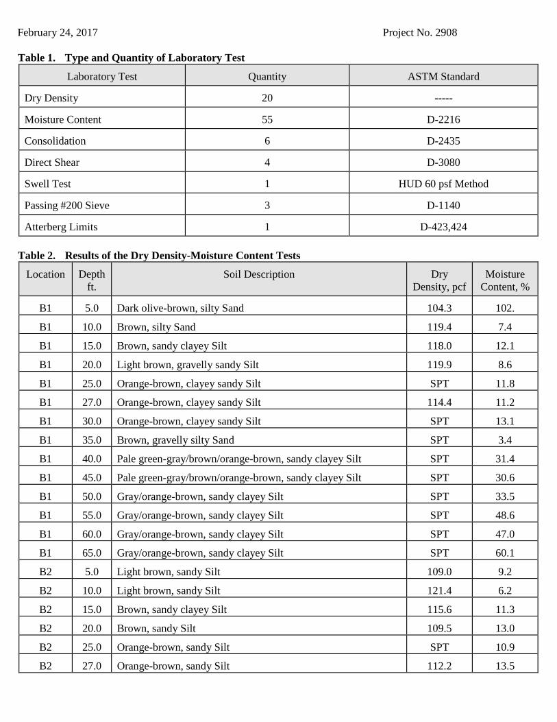
February 24, 2017 Project No. 2908 Table 1. Type and Quantity of Laboratory Test
Laboratory Test
Quantity
ASTM Standard
Dry Density
20
-----
Moisture Content
55
D-2216
Consolidation 6
D-2435
Direct Shear 4
D-3080
Swell Test 1
HUD 60 psf Method
Passing #200 Sieve 3
D-1140
Atterberg Limits 1
D-423,424
Table 2. Results of the Dry Density-Moisture Content Tests
Location
Depth
ft.
Soil Description
Dry
Density, pcf
Moisture
Content, %
B1 5.0 Dark olive-brown, silty Sand 104.3 102.
B1 10.0 Brown, silty Sand 119.4 7.4
B1 15.0 Brown, sandy clayey Silt 118.0 12.1
B1 20.0 Light brown, gravelly sandy Silt 119.9 8.6
B1 25.0 Orange-brown, clayey sandy Silt SPT 11.8
B1 27.0 Orange-brown, clayey sandy Silt 114.4 11.2
B1 30.0 Orange-brown, clayey sandy Silt SPT 13.1
B1 35.0 Brown, gravelly silty Sand SPT 3.4
B1 40.0 Pale green-gray/brown/orange-brown, sandy clayey Silt SPT 31.4
B1 45.0 Pale green-gray/brown/orange-brown, sandy clayey Silt SPT 30.6
B1 50.0 Gray/orange-brown, sandy clayey Silt SPT 33.5
B1 55.0 Gray/orange-brown, sandy clayey Silt SPT 48.6
B1 60.0 Gray/orange-brown, sandy clayey Silt SPT 47.0
B1 65.0 Gray/orange-brown, sandy clayey Silt SPT 60.1
B2 5.0 Light brown, sandy Silt 109.0 9.2
B2 10.0 Light brown, sandy Silt 121.4 6.2
B2 15.0 Brown, sandy clayey Silt 115.6 11.3
B2 20.0 Brown, sandy Silt 109.5 13.0
B2 25.0 Orange-brown, sandy Silt SPT 10.9
B2 27.0 Orange-brown, sandy Silt 112.2 13.5

February 24, 2017 Project No. 2908 Table 2. Results of the Dry Density-Moisture Content Tests (Continued)
Location
Depth
ft.
Soil Description
Dry
Density, pcf
Moisture
Content, %
B2 30.0 Orange-brown, silty Sand SPT 4.0
B2 35.0 Orange-brown, silty Sand SPT 16.0
B2 40.0 Orange-brown, gravelly silty Sand SPT 3.0
B2 45.0 Brown, silty Clay SPT 16.5
B2 50.0 Pale tan, clayey Silt SPT 61.3
B2 55.0 Pale tan, clayey Silt SPT 69.4
B2 60.0 Pale tan, clayey Silt SPT 61.8
B2 65.0 Pale tan, clayey Silt SPT 62.1
B3 5.0 Brown, sandy Silt 105.1 9.1
B3 10.0 Red-brown, sandy silty Clay 117.4 14.2
B3 15.0 Brown, gravelly silty Sand 118.2 9.6
B3 20.0 Orange-brown, Sand 115.2 6.3
B3 25.0 Brown, silty Sand SPT 6.4
B3 27.0 Orange-brown, Sand 113.6 5.2
B3 30.0 Orange-brown, Sand SPT 6.9
B3 35.0 Brown, silty Sand SPT 21.8
B3 40.0 Brown, silty Sand SPT 20.4
B3 45.0 Brown, silty Sand SPT 5.6
B3 50.0 Brown, Sand with silt SPT 8.0
B3 55.0 Dark brown, clayey sandy Silt SPT 25.0
B3 60.0 Dark brown, clayey Silt SPT 27.3
B3 65.0 Pale green-gray, clayey Silt SPT 37.4
B4 5.0 Dark brown, sandy Silt SPT 11.9
B4 10.0 Dark brown, clayey Silt SPT 13.0
B4 15.0 Red-brown, clayey sandy Silt SPT 11.6
B4 20.0 Red-brown, clayey sandy Silt SPT 15.1
B4 25.0 Brown, clayey Silt SPT 12.3
B5 5.0 Brown, sandy clayey Silt SPT 10.4
B5 10.0 Brown, sandy clayey Silt SPT 13.6
B5 15.0 Brown, clayey sandy Silt SPT 7.8

February 24, 2017 Project No. 2908 Table 2. Results of the Dry Density-Moisture Content Tests (Continued)
Location
Depth
ft.
Soil Description
Dry
Density, pcf
Moisture
Content, %
B5 20.0 Pale brown-gray, silty Sand SPT 6.0
B6 1.5 Dark brown, silty Sand 102.8 13.8
B6 3.5 Dark brown, sandy Silt 103.3 19.1
B6 5.5 Dark brown, sandy Silt 100.2 21.0
B7 4.5 Dark brown, gravelly Sand 114.8 5.9
B8 1.5 Dark brown, sandy Silt and silty Sand 116.1 11.6 Table 3. Results of Swell Test
Location
Depth
ft
Soil Descriptions
% Swell
B1
15.0
Brown, sandy clayey Silt
1.2 (Very Low)
Table 4. Results of Percentage Passing #200 Sieve Test
Location
Depth
ft
Soil Description
% Passing #200 Sieve
B1 30.0 Orange-brown, clayey sandy Silt 62.0
B1 50.0 Gray/orange-brown, sandy clayey Silt 69.0
B2 35.0 Orange-brown, silty Sand 34.0 Table 5. Results of Atterberg Limits Tests
Location
Depth
ft
Soil Description
Liquid Limit
Plastic Limit
Plasticity
Index
U.S.C.S. Symbol
B2
45.0 Brown, silty Clay 48 25 23 CL


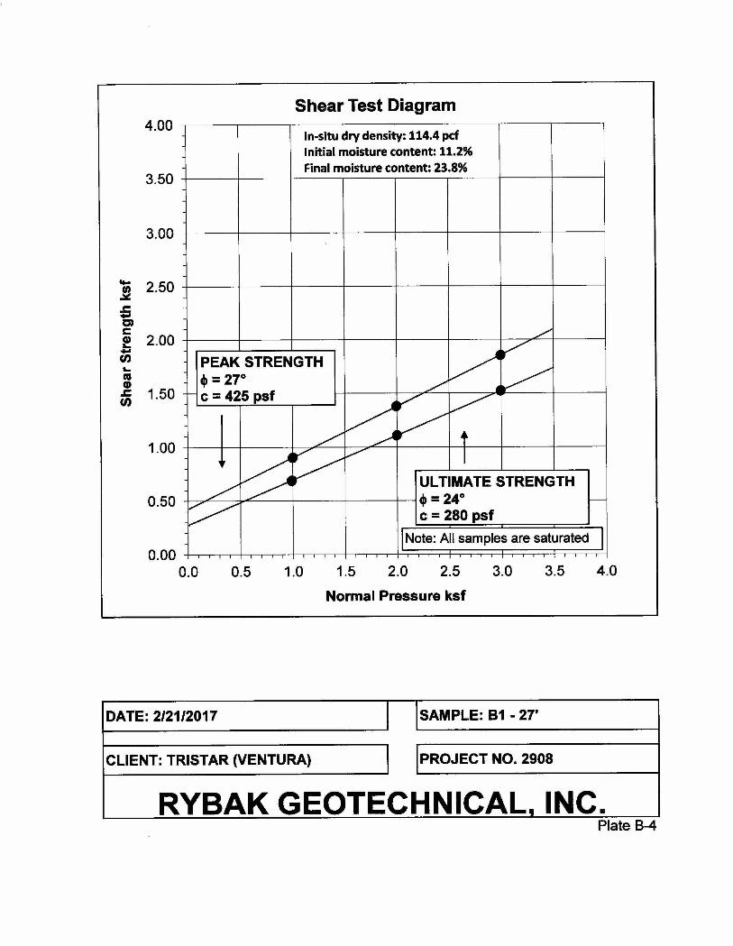

RYBAK GEOTECHNICAL, INC.Plate C-1
Before Saturation After Saturation
DATE: 2/23/2017 SAMPLE: B6-3.5
CLIENT: TRISTAR (VENTURA) PROJECT NO. 2908
0.0
2.0
4.0
6.0
8.0
10.0
12.0
14.0
16.0
0.1 1 10
Pe
rce
nt
Co
ns
oli
da
tio
n
Applied Pressure (ksf)
Consolidation Test
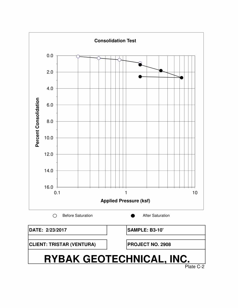
RYBAK GEOTECHNICAL, INC.Plate C-2
Before Saturation After Saturation
DATE: 2/23/2017 SAMPLE: B3-10'
CLIENT: TRISTAR (VENTURA) PROJECT NO. 2908
0.0
2.0
4.0
6.0
8.0
10.0
12.0
14.0
16.0
0.1 1 10
Pe
rce
nt
Co
ns
oli
da
tio
n
Applied Pressure (ksf)
Consolidation Test

RYBAK GEOTECHNICAL, INC.Plate C-3
Before Saturation After Saturation
DATE: 2/23/2017 SAMPLE: B2-15'
CLIENT: TRISTAR (VENTURA) PROJECT NO. 2908
0.0
2.0
4.0
6.0
8.0
10.0
12.0
14.0
16.0
0.1 1 10
Pe
rce
nt
Co
ns
oli
da
tio
n
Applied Pressure (ksf)
Consolidation Test

RYBAK GEOTECHNICAL, INC.Plate C-4
Before Saturation After Saturation
DATE: 2/23/2017 SAMPLE: B3-27'
CLIENT: TRISTAR (VENTURA) PROJECT NO. 2908
0.0
2.0
4.0
6.0
8.0
10.0
12.0
14.0
16.0
0.1 1 10
Pe
rce
nt
Co
ns
oli
da
tio
n
Applied Pressure (ksf)
Consolidation Test

RYBAK GEOTECHNICAL, INC.Plate C-5
Before Saturation After Saturation
DATE: 2/23/2017 SAMPLE: B3-35'
CLIENT: TRISTAR (VENTURA) PROJECT NO. 2908
0.0
2.0
4.0
6.0
8.0
10.0
12.0
14.0
16.0
0.1 1 10
Pe
rce
nt
Co
ns
oli
da
tio
n
Applied Pressure (ksf)
Consolidation Test

RYBAK GEOTECHNICAL, INC.Plate C-6
Before Saturation After Saturation
DATE: 2/23/2017 SAMPLE: B1-45'
CLIENT: TRISTAR (VENTURA) PROJECT NO. 2908
0.0
2.0
4.0
6.0
8.0
10.0
12.0
14.0
16.0
0.1 1 10
Pe
rce
nt
Co
ns
oli
da
tio
n
Applied Pressure (ksf)
Consolidation Test

Design Maps Detailed Report
From Figure 22-1 [1]
From Figure 22-2 [2]
ASCE 7-10 Standard (34.1607°N, 118.5044°W)
Site Class D – “Stiff Soil”, Risk Category I/II/III
Section 11.4.1 — Mapped Acceleration Parameters
Note: Ground motion values provided below are for the direction of maximum horizontal
spectral response acceleration. They have been converted from corresponding geometric
mean ground motions computed by the USGS by applying factors of 1.1 (to obtain SS) and
1.3 (to obtain S1). Maps in the 2010 ASCE-7 Standard are provided for Site Class B.
Adjustments for other Site Classes are made, as needed, in Section 11.4.3.
SS = 2.061 g
S1 = 0.725 g
Section 11.4.2 — Site Class
The authority having jurisdiction (not the USGS), site-specific geotechnical data, and/or
the default has classified the site as Site Class D, based on the site soil properties in
accordance with Chapter 20.
Table 20.3–1 Site Classification
Site Class vS N or Nch su
A. Hard Rock >5,000 ft/s N/A N/A
B. Rock 2,500 to 5,000 ft/s N/A N/A
C. Very dense soil and soft rock 1,200 to 2,500 ft/s >50 >2,000 psf
D. Stiff Soil 600 to 1,200 ft/s 15 to 50 1,000 to 2,000 psf
E. Soft clay soil <600 ft/s <15 <1,000 psf
Any profile with more than 10 ft of soil having the characteristics:
• Plasticity index PI > 20,
• Moisture content w ≥ 40%, and
• Undrained shear strength su < 500 psf
F. Soils requiring site response
analysis in accordance with Section
21.1
See Section 20.3.1
For SI: 1ft/s = 0.3048 m/s 1lb/ft² = 0.0479 kN/m²
Page 1 of 6Design Maps Detailed Report
2/22/2017https://earthquake.usgs.gov/cn2/designmaps/us/report.php?template=minimal&latitude=34...

Section 11.4.3 — Site Coefficients and Risk–Targeted Maximum Considered Earthquake
(MCER) Spectral Response Acceleration Parameters
Table 11.4–1: Site Coefficient Fa
Site Class Mapped MCE R Spectral Response Acceleration Parameter at Short Period
SS ≤ 0.25 SS = 0.50 SS = 0.75 SS = 1.00 SS ≥ 1.25
A 0.8 0.8 0.8 0.8 0.8
B 1.0 1.0 1.0 1.0 1.0
C 1.2 1.2 1.1 1.0 1.0
D 1.6 1.4 1.2 1.1 1.0
E 2.5 1.7 1.2 0.9 0.9
F See Section 11.4.7 of ASCE 7
Note: Use straight–line interpolation for intermediate values of SS
For Site Class = D and SS = 2.061 g, Fa = 1.000
Table 11.4–2: Site Coefficient Fv
Site Class Mapped MCE R Spectral Response Acceleration Parameter at 1–s Period
S1 ≤ 0.10 S1 = 0.20 S1 = 0.30 S1 = 0.40 S1 ≥ 0.50
A 0.8 0.8 0.8 0.8 0.8
B 1.0 1.0 1.0 1.0 1.0
C 1.7 1.6 1.5 1.4 1.3
D 2.4 2.0 1.8 1.6 1.5
E 3.5 3.2 2.8 2.4 2.4
F See Section 11.4.7 of ASCE 7
Note: Use straight–line interpolation for intermediate values of S1
For Site Class = D and S1 = 0.725 g, Fv = 1.500
Page 2 of 6Design Maps Detailed Report
2/22/2017https://earthquake.usgs.gov/cn2/designmaps/us/report.php?template=minimal&latitude=34...
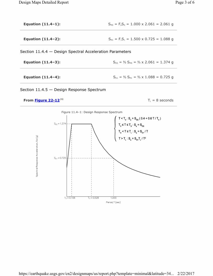
Equation (11.4–1):
Equation (11.4–2):
Equation (11.4–3):
Equation (11.4–4):
From Figure 22-12 [3]
SMS = FaSS = 1.000 x 2.061 = 2.061 g
SM1 = FvS1 = 1.500 x 0.725 = 1.088 g
Section 11.4.4 — Design Spectral Acceleration Parameters
SDS = ⅔ SMS = ⅔ x 2.061 = 1.374 g
SD1 = ⅔ SM1 = ⅔ x 1.088 = 0.725 g
Section 11.4.5 — Design Response Spectrum
TL = 8 seconds
Figure 11.4–1: Design Response Spectrum
Page 3 of 6Design Maps Detailed Report
2/22/2017https://earthquake.usgs.gov/cn2/designmaps/us/report.php?template=minimal&latitude=34...

Section 11.4.6 — Risk-Targeted Maximum Considered Earthquake (MCER) Response
Spectrum
The MCER Response Spectrum is determined by multiplying the design response spectrum above by
1.5.
Page 4 of 6Design Maps Detailed Report
2/22/2017https://earthquake.usgs.gov/cn2/designmaps/us/report.php?template=minimal&latitude=34...

From Figure 22-7 [4]
Equation (11.8–1):
From Figure 22-17 [5]
From Figure 22-18 [6]
Section 11.8.3 — Additional Geotechnical Investigation Report Requirements for Seismic
Design Categories D through F
PGA = 0.715
PGAM = FPGAPGA = 1.000 x 0.715 = 0.715 g
Table 11.8–1: Site Coefficient FPGA
Site
Class
Mapped MCE Geometric Mean Peak Ground Acceleration, PGA
PGA ≤
0.10
PGA =
0.20
PGA =
0.30
PGA =
0.40
PGA ≥
0.50
A 0.8 0.8 0.8 0.8 0.8
B 1.0 1.0 1.0 1.0 1.0
C 1.2 1.2 1.1 1.0 1.0
D 1.6 1.4 1.2 1.1 1.0
E 2.5 1.7 1.2 0.9 0.9
F See Section 11.4.7 of ASCE 7
Note: Use straight–line interpolation for intermediate values of PGA
For Site Class = D and PGA = 0.715 g, FPGA = 1.000
Section 21.2.1.1 — Method 1 (from Chapter 21 – Site-Specific Ground Motion Procedures
for Seismic Design)
CRS = 1.015
CR1 = 1.031
Page 5 of 6Design Maps Detailed Report
2/22/2017https://earthquake.usgs.gov/cn2/designmaps/us/report.php?template=minimal&latitude=34...
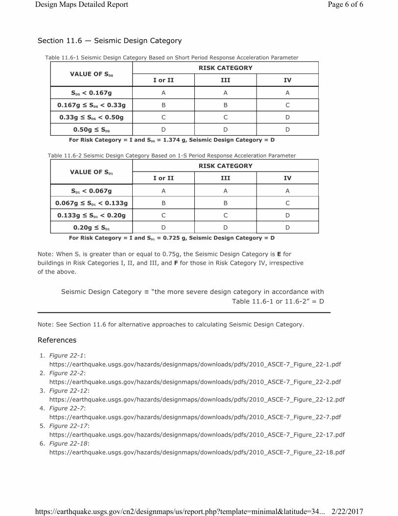
Section 11.6 — Seismic Design Category
Table 11.6-1 Seismic Design Category Based on Short Period Response Acceleration Parameter
VALUE OF SDS
RISK CATEGORY
I or II III IV
SDS < 0.167g A A A
0.167g ≤ SDS < 0.33g B B C
0.33g ≤ SDS < 0.50g C C D
0.50g ≤ SDS D D D
For Risk Category = I and SDS = 1.374 g, Seismic Design Category = D
Table 11.6-2 Seismic Design Category Based on 1-S Period Response Acceleration Parameter
VALUE OF SD1
RISK CATEGORY
I or II III IV
SD1 < 0.067g A A A
0.067g ≤ SD1 < 0.133g B B C
0.133g ≤ SD1 < 0.20g C C D
0.20g ≤ SD1 D D D
For Risk Category = I and SD1 = 0.725 g, Seismic Design Category = D
Note: When S1 is greater than or equal to 0.75g, the Seismic Design Category is E for
buildings in Risk Categories I, II, and III, and F for those in Risk Category IV, irrespective
of the above.
Seismic Design Category ≡ “the more severe design category in accordance with
Table 11.6-1 or 11.6-2” = D
Note: See Section 11.6 for alternative approaches to calculating Seismic Design Category.
References
1. Figure 22-1:
https://earthquake.usgs.gov/hazards/designmaps/downloads/pdfs/2010_ASCE-7_Figure_22-1.pdf
2. Figure 22-2:
https://earthquake.usgs.gov/hazards/designmaps/downloads/pdfs/2010_ASCE-7_Figure_22-2.pdf
3. Figure 22-12:
https://earthquake.usgs.gov/hazards/designmaps/downloads/pdfs/2010_ASCE-7_Figure_22-12.pdf
4. Figure 22-7:
https://earthquake.usgs.gov/hazards/designmaps/downloads/pdfs/2010_ASCE-7_Figure_22-7.pdf
5. Figure 22-17:
https://earthquake.usgs.gov/hazards/designmaps/downloads/pdfs/2010_ASCE-7_Figure_22-17.pdf
6. Figure 22-18:
https://earthquake.usgs.gov/hazards/designmaps/downloads/pdfs/2010_ASCE-7_Figure_22-18.pdf
Page 6 of 6Design Maps Detailed Report
2/22/2017https://earthquake.usgs.gov/cn2/designmaps/us/report.php?template=minimal&latitude=34...

0
10
20
30
40
50
60
70
80
90
Closest Distance, Rcd (km)
0
10
20
30
40
50
60
70
80
90
Clo
sest D
istance
, Rcd
(km)
5.0
5.5
6.0
6.5
7.0
7.5
8.0
MAGNITUDE (M
w)
5.0
5.5
6.0
6.5
7.0
7.5
8.0
MA
GN
ITU
DE
(M
w)
5101520
% Contribution to Hazard
PS
H D
eaggre
gat
ion o
n N
EH
RP
D so
ilT
rist
ar_
Ven
tura
118.5
04
o W
, 34.1
61 N
.P
eak H
ori
z. G
round A
ccel
.>=
0.4
53
9 g
Ann.
Exce
edan
ce R
ate
.211E
-02
. M
ean
Ret
urn
Tim
e 47
5 y
ears
Mea
n (
R,M
,ε0)
19.2
km
, 6.7
6, 0
.99
Modal
(R
,M,ε
0)
=
15.4
km
, 6
.61
, 0
.93
(fr
om
pea
k R
,M b
in)
Modal
(R
,M,ε
*)
= 1
5.6
km
, 6
.61
, 1
to
2 s
igm
a (
fro
m p
eak
R,M
,ε b
in)
Bin
nin
g:
Del
taR
10. km
, del
taM
=0
.2, D
elta
ε=
1.0
200910 U
PD
AT
E
ε0 <
-2
-2 <
ε0 <
-1
-1 <
ε0 <
-0.5
-0.5
< ε
0 <
0
0 <
ε0 <
0.5
0.5
< ε
0 <
1
1 <
ε0 <
2
2 <
ε0 <
3
Pro
b.
SA
, P
GA
<m
ed
ian
(R,M
)>
med
ian
GM
T2017 F
eb 2
2 1
8:0
4:2
4D
ista
nce (
R),
mag
nit
ud
e (
M),
ep
sil
on
(E
0,E
) d
eag
gre
gati
on
fo
r a s
ite o
n s
oil
wit
h a
vera
ge v
s=
250.
m/s
to
p 3
0 m
. U
SG
S C
GH
T P
SH
A2008 U
PD
AT
E
B
ins w
ith
lt
0.0
5%
co
ntr
ib.
om
itte
d

*****************************
* *
* L I Q U E F Y 2 *
* *
* Version 1.50 *
* *
*****************************
EMPIRICAL PREDICTION OF
EARTHQUAKE-INDUCED LIQUEFACTION POTENTIAL
JOB NUMBER: 2908 DATE: 02-22-
2017
JOB NAME: Triv12
SOIL-PROFILE NAME: triv12.LDW
BORING GROUNDWATER DEPTH: 66.50 ft
CALCULATION GROUNDWATER DEPTH: 30.00 ft
DESIGN EARTHQUAKE MAGNITUDE: 6.61 Mw
SITE PEAK GROUND ACCELERATION: 0.715 g
BOREHOLE DIAMETER CORRECTION FACTOR: 1.00
SAMPLER SIZE CORRECTION FACTOR: 1.20
N60 HAMMER CORRECTION FACTOR: 1.30
MAGNITUDE SCALING FACTOR METHOD: Idriss (1998, in press)
Magnitude Scaling Factor: 1.242
rd-CORRECTION METHOD: NCEER (1997)
FIELD SPT N-VALUES ARE CORRECTED FOR THE LENGTH OF THE DRIVE RODS.
Rod Stick-Up Above Ground: 0.0 ft
CN NORMALIZATION FACTOR: 1.044 tsf
MINIMUM CN VALUE: 0.6

------------------- -----------------------------
NCEER [1997] Method LIQUEFACTION ANALYSIS SUMMARY PAGE 1
------------------- -----------------------------
File Name: triv12.OUT
------------------------------------------------------------------------------
| CALC.| TOTAL| EFF. |FIELD | FC | | CORR.|LIQUE.| |INDUC.|LIQUE.
SOIL| DEPTH|STRESS|STRESS| N |DELTA| C |(N1)60|RESIST| r |STRESS|SAFETY
NO.| (ft) | (tsf)| (tsf)|(B/ft)|N1_60| N |(B/ft)| RATIO| d | RATIO|FACTOR
----+------+------+------+------+-----+-----+------+------+-----+------+------
1 | 0.25| 0.015| 0.015| 10 | ~ | * | * | * | * | * | **
1 | 0.75| 0.045| 0.045| 10 | ~ | * | * | * | * | * | **
1 | 1.25| 0.075| 0.075| 10 | ~ | * | * | * | * | * | **
1 | 1.75| 0.105| 0.105| 10 | ~ | * | * | * | * | * | **
1 | 2.25| 0.135| 0.135| 10 | ~ | * | * | * | * | * | **
1 | 2.75| 0.165| 0.165| 10 | ~ | * | * | * | * | * | **
1 | 3.25| 0.195| 0.195| 10 | ~ | * | * | * | * | * | **
1 | 3.75| 0.225| 0.225| 10 | ~ | * | * | * | * | * | **
1 | 4.25| 0.255| 0.255| 10 | ~ | * | * | * | * | * | **
1 | 4.75| 0.285| 0.285| 10 | ~ | * | * | * | * | * | **
1 | 5.25| 0.315| 0.315| 10 | ~ | * | * | * | * | * | **
1 | 5.75| 0.345| 0.345| 10 | ~ | * | * | * | * | * | **
1 | 6.25| 0.375| 0.375| 10 | ~ | * | * | * | * | * | **
1 | 6.75| 0.405| 0.405| 10 | ~ | * | * | * | * | * | **
1 | 7.25| 0.435| 0.435| 10 | ~ | * | * | * | * | * | **
1 | 7.75| 0.465| 0.465| 10 | ~ | * | * | * | * | * | **
1 | 8.25| 0.495| 0.495| 10 | ~ | * | * | * | * | * | **
1 | 8.75| 0.525| 0.525| 10 | ~ | * | * | * | * | * | **
1 | 9.25| 0.555| 0.555| 10 | ~ | * | * | * | * | * | **
1 | 9.75| 0.585| 0.585| 10 | ~ | * | * | * | * | * | **
1 | 10.25| 0.615| 0.615| 10 | ~ | * | * | * | * | * | **
1 | 10.75| 0.645| 0.645| 10 | ~ | * | * | * | * | * | **
1 | 11.25| 0.675| 0.675| 10 | ~ | * | * | * | * | * | **
1 | 11.75| 0.705| 0.705| 10 | ~ | * | * | * | * | * | **
1 | 12.25| 0.735| 0.735| 10 | ~ | * | * | * | * | * | **
1 | 12.75| 0.765| 0.765| 10 | ~ | * | * | * | * | * | **
1 | 13.25| 0.795| 0.795| 10 | ~ | * | * | * | * | * | **
1 | 13.75| 0.825| 0.825| 10 | ~ | * | * | * | * | * | **
1 | 14.25| 0.855| 0.855| 10 | ~ | * | * | * | * | * | **
1 | 14.75| 0.885| 0.885| 10 | ~ | * | * | * | * | * | **
1 | 15.25| 0.915| 0.915| 10 | ~ | * | * | * | * | * | **
1 | 15.75| 0.945| 0.945| 10 | ~ | * | * | * | * | * | **
1 | 16.25| 0.975| 0.975| 10 | ~ | * | * | * | * | * | **
1 | 16.75| 1.005| 1.005| 10 | ~ | * | * | * | * | * | **
1 | 17.25| 1.035| 1.035| 10 | ~ | * | * | * | * | * | **
1 | 17.75| 1.065| 1.065| 10 | ~ | * | * | * | * | * | **
1 | 18.25| 1.095| 1.095| 10 | ~ | * | * | * | * | * | **
1 | 18.75| 1.125| 1.125| 10 | ~ | * | * | * | * | * | **
1 | 19.25| 1.155| 1.155| 10 | ~ | * | * | * | * | * | **
1 | 19.75| 1.185| 1.185| 10 | ~ | * | * | * | * | * | **
1 | 20.25| 1.215| 1.215| 10 | ~ | * | * | * | * | * | **
1 | 20.75| 1.245| 1.245| 10 | ~ | * | * | * | * | * | **
1 | 21.25| 1.275| 1.275| 10 | ~ | * | * | * | * | * | **

------------------- -----------------------------
NCEER [1997] Method LIQUEFACTION ANALYSIS SUMMARY PAGE 2
------------------- -----------------------------
File Name: triv12.OUT
------------------------------------------------------------------------------
| CALC.| TOTAL| EFF. |FIELD | FC | | CORR.|LIQUE.| |INDUC.|LIQUE.
SOIL| DEPTH|STRESS|STRESS| N |DELTA| C |(N1)60|RESIST| r |STRESS|SAFETY
NO.| (ft) | (tsf)| (tsf)|(B/ft)|N1_60| N |(B/ft)| RATIO| d | RATIO|FACTOR
----+------+------+------+------+-----+-----+------+------+-----+------+------
1 | 21.75| 1.305| 1.305| 10 | ~ | * | * | * | * | * | **
1 | 22.25| 1.335| 1.335| 10 | ~ | * | * | * | * | * | **
1 | 22.75| 1.365| 1.365| 10 | ~ | * | * | * | * | * | **
1 | 23.25| 1.395| 1.395| 10 | ~ | * | * | * | * | * | **
1 | 23.75| 1.425| 1.425| 10 | ~ | * | * | * | * | * | **
1 | 24.25| 1.455| 1.455| 10 | ~ | * | * | * | * | * | **
1 | 24.75| 1.485| 1.485| 10 | ~ | * | * | * | * | * | **
1 | 25.25| 1.515| 1.515| 10 | ~ | * | * | * | * | * | **
1 | 25.75| 1.545| 1.545| 10 | ~ | * | * | * | * | * | **
1 | 26.25| 1.575| 1.575| 10 | ~ | * | * | * | * | * | **
1 | 26.75| 1.605| 1.605| 10 | ~ | * | * | * | * | * | **
1 | 27.25| 1.635| 1.635| 10 | ~ | * | * | * | * | * | **
1 | 27.75| 1.665| 1.665| 10 | ~ | * | * | * | * | * | **
1 | 28.25| 1.695| 1.695| 10 | ~ | * | * | * | * | * | **
1 | 28.75| 1.725| 1.725| 10 | ~ | * | * | * | * | * | **
1 | 29.25| 1.755| 1.755| 10 | ~ | * | * | * | * | * | **
1 | 29.75| 1.785| 1.785| 10 | ~ | * | * | * | * | * | **
2 | 30.25| 1.815| 1.807| 24 |10.57|0.758| 39.0 |Infin |0.928| 0.433|NonLiq
2 | 30.75| 1.845| 1.822| 24 |10.57|0.758| 39.0 |Infin |0.924| 0.435|NonLiq
2 | 31.25| 1.875| 1.836| 24 |10.57|0.758| 39.0 |Infin |0.920| 0.437|NonLiq
2 | 31.75| 1.905| 1.850| 24 |10.57|0.758| 39.0 |Infin |0.916| 0.438|NonLiq
3 | 32.25| 1.935| 1.865| 38 | 0.05|0.703| 41.7 |Infin |0.912| 0.440|NonLiq
3 | 32.75| 1.965| 1.879| 38 | 0.05|0.703| 41.7 |Infin |0.907| 0.441|NonLiq
3 | 33.25| 1.995| 1.894| 38 | 0.05|0.703| 41.7 |Infin |0.903| 0.442|NonLiq
3 | 33.75| 2.025| 1.908| 38 | 0.05|0.703| 41.7 |Infin |0.899| 0.444|NonLiq
3 | 34.25| 2.055| 1.922| 38 | 0.05|0.703| 41.7 |Infin |0.895| 0.445|NonLiq
3 | 34.75| 2.085| 1.937| 38 | 0.05|0.703| 41.7 |Infin |0.891| 0.446|NonLiq
3 | 35.25| 2.115| 1.951| 38 | 0.05|0.703| 41.7 |Infin |0.887| 0.447|NonLiq
3 | 35.75| 2.145| 1.966| 38 | 0.05|0.703| 41.7 |Infin |0.883| 0.448|NonLiq
3 | 36.25| 2.175| 1.980| 38 | 0.05|0.703| 41.7 |Infin |0.879| 0.449|NonLiq
4 | 36.75| 2.205| 1.994| 35 | 0.05|0.657| 35.9 |Infin |0.875| 0.450|NonLiq
4 | 37.25| 2.235| 2.009| 35 | 0.05|0.657| 35.9 |Infin |0.871| 0.450|NonLiq
4 | 37.75| 2.265| 2.023| 35 | 0.05|0.657| 35.9 |Infin |0.867| 0.451|NonLiq
4 | 38.25| 2.295| 2.038| 35 | 0.05|0.657| 35.9 |Infin |0.863| 0.452|NonLiq
4 | 38.75| 2.325| 2.052| 35 | 0.05|0.657| 35.9 |Infin |0.859| 0.452|NonLiq
4 | 39.25| 2.355| 2.066| 35 | 0.05|0.657| 35.9 |Infin |0.855| 0.453|NonLiq
4 | 39.75| 2.385| 2.081| 35 | 0.05|0.657| 35.9 |Infin |0.851| 0.453|NonLiq
4 | 40.25| 2.415| 2.095| 35 | 0.05|0.657| 35.9 |Infin |0.846| 0.453|NonLiq
4 | 40.75| 2.445| 2.110| 35 | 0.05|0.657| 35.9 |Infin |0.842| 0.454|NonLiq
4 | 41.25| 2.475| 2.124| 35 | 0.05|0.657| 35.9 |Infin |0.838| 0.454|NonLiq
4 | 41.75| 2.505| 2.138| 35 | 0.05|0.657| 35.9 |Infin |0.834| 0.454|NonLiq
4 | 42.25| 2.535| 2.153| 35 | 0.05|0.657| 35.9 |Infin |0.830| 0.454|NonLiq
5 | 42.75| 2.565| 2.167| 30 |10.70|0.620| 39.7 |Infin |0.826| 0.454|NonLiq
5 | 43.25| 2.595| 2.182| 30 |10.70|0.620| 39.7 |Infin |0.822| 0.454|NonLiq
------------------- -----------------------------
NCEER [1997] Method LIQUEFACTION ANALYSIS SUMMARY PAGE 3

------------------- -----------------------------
File Name: triv12.OUT
------------------------------------------------------------------------------
| CALC.| TOTAL| EFF. |FIELD | FC | | CORR.|LIQUE.| |INDUC.|LIQUE.
SOIL| DEPTH|STRESS|STRESS| N |DELTA| C |(N1)60|RESIST| r |STRESS|SAFETY
NO.| (ft) | (tsf)| (tsf)|(B/ft)|N1_60| N |(B/ft)| RATIO| d | RATIO|FACTOR
----+------+------+------+------+-----+-----+------+------+-----+------+------
5 | 43.75| 2.625| 2.196| 30 |10.70|0.620| 39.7 |Infin |0.818| 0.454|NonLiq
5 | 44.25| 2.655| 2.210| 30 |10.70|0.620| 39.7 |Infin |0.814| 0.454|NonLiq
5 | 44.75| 2.685| 2.225| 30 |10.70|0.620| 39.7 |Infin |0.810| 0.454|NonLiq
5 | 45.25| 2.715| 2.239| 30 |10.70|0.620| 39.7 |Infin |0.806| 0.454|NonLiq
5 | 45.75| 2.745| 2.254| 30 |10.70|0.620| 39.7 |Infin |0.802| 0.454|NonLiq
5 | 46.25| 2.775| 2.268| 30 |10.70|0.620| 39.7 |Infin |0.798| 0.454|NonLiq
5 | 46.75| 2.805| 2.282| 30 |10.70|0.620| 39.7 |Infin |0.794| 0.453|NonLiq
5 | 47.25| 2.835| 2.297| 30 |10.70|0.620| 39.7 |Infin |0.789| 0.453|NonLiq
5 | 47.75| 2.865| 2.311| 30 |10.70|0.620| 39.7 |Infin |0.785| 0.452|NonLiq
6 | 48.25| 2.895| 2.326| 33 | 0.04|0.600| 30.9 |Infin |0.781| 0.452|NonLiq
6 | 48.75| 2.925| 2.340| 33 | 0.04|0.600| 30.9 |Infin |0.777| 0.452|NonLiq
6 | 49.25| 2.955| 2.354| 33 | 0.04|0.600| 30.9 |Infin |0.773| 0.451|NonLiq
6 | 49.75| 2.985| 2.369| 33 | 0.04|0.600| 30.9 |Infin |0.769| 0.450|NonLiq
6 | 50.25| 3.015| 2.383| 33 | 0.04|0.600| 30.9 |Infin |0.765| 0.450|NonLiq
6 | 50.75| 3.045| 2.398| 33 | 0.04|0.600| 30.9 |Infin |0.761| 0.449|NonLiq
6 | 51.25| 3.075| 2.412| 33 | 0.04|0.600| 30.9 |Infin |0.757| 0.448|NonLiq
6 | 51.75| 3.105| 2.426| 33 | 0.04|0.600| 30.9 |Infin |0.753| 0.448|NonLiq
6 | 52.25| 3.135| 2.441| 33 | 0.04|0.600| 30.9 |Infin |0.749| 0.447|NonLiq
7 | 52.75| 3.165| 2.455| 47 | 0.05|0.600| 44.0 |Infin |0.745| 0.446|NonLiq
7 | 53.25| 3.195| 2.470| 47 | 0.05|0.600| 44.0 |Infin |0.741| 0.445|NonLiq
7 | 53.75| 3.225| 2.484| 47 | 0.05|0.600| 44.0 |Infin |0.737| 0.444|NonLiq
7 | 54.25| 3.255| 2.498| 47 | 0.05|0.600| 44.0 |Infin |0.732| 0.444|NonLiq
7 | 54.75| 3.285| 2.513| 47 | 0.05|0.600| 44.0 |Infin |0.728| 0.443|NonLiq
7 | 55.25| 3.315| 2.527| 47 | 0.05|0.600| 44.0 |Infin |0.724| 0.442|NonLiq
7 | 55.75| 3.345| 2.542| 47 | 0.05|0.600| 44.0 |Infin |0.720| 0.441|NonLiq
7 | 56.25| 3.375| 2.556| 47 | 0.05|0.600| 44.0 |Infin |0.716| 0.440|NonLiq
7 | 56.75| 3.405| 2.570| 47 | 0.05|0.600| 44.0 |Infin |0.712| 0.438|NonLiq
7 | 57.25| 3.435| 2.585| 47 | 0.05|0.600| 44.0 |Infin |0.708| 0.437|NonLiq
8 | 57.75| 3.465| 2.599| 55 | 0.06|0.600| 51.5 |Infin |0.704| 0.436|NonLiq
8 | 58.25| 3.495| 2.614| 55 | 0.06|0.600| 51.5 |Infin |0.700| 0.435|NonLiq
8 | 58.75| 3.525| 2.628| 55 | 0.06|0.600| 51.5 |Infin |0.696| 0.434|NonLiq
8 | 59.25| 3.555| 2.642| 55 | 0.06|0.600| 51.5 |Infin |0.692| 0.433|NonLiq
8 | 59.75| 3.585| 2.657| 55 | 0.06|0.600| 51.5 |Infin |0.688| 0.431|NonLiq
8 | 60.25| 3.615| 2.671| 55 | 0.06|0.600| 51.5 |Infin |0.684| 0.430|NonLiq
8 | 60.75| 3.645| 2.686| 55 | 0.06|0.600| 51.5 |Infin |0.680| 0.429|NonLiq
8 | 61.25| 3.675| 2.700| 55 | 0.06|0.600| 51.5 |Infin |0.676| 0.427|NonLiq
8 | 61.75| 3.705| 2.714| 55 | 0.06|0.600| 51.5 |Infin |0.671| 0.426|NonLiq
8 | 62.25| 3.735| 2.729| 55 | 0.06|0.600| 51.5 |Infin |0.667| 0.425|NonLiq
9 | 62.75| 3.765| 2.743| 45 | 0.05|0.600| 42.2 |Infin |0.663| 0.423|NonLiq
9 | 63.25| 3.795| 2.758| 45 | 0.05|0.600| 42.2 |Infin |0.659| 0.422|NonLiq
9 | 63.75| 3.825| 2.772| 45 | 0.05|0.600| 42.2 |Infin |0.655| 0.420|NonLiq
9 | 64.25| 3.855| 2.786| 45 | 0.05|0.600| 42.2 |Infin |0.651| 0.419|NonLiq
9 | 64.75| 3.885| 2.801| 45 | 0.05|0.600| 42.2 |Infin |0.647| 0.417|NonLiq
9 | 65.25| 3.915| 2.815| 45 | 0.05|0.600| 42.2 |Infin |0.643| 0.416|NonLiq
------------------- -----------------------------
NCEER [1997] Method LIQUEFACTION ANALYSIS SUMMARY PAGE 4
------------------- -----------------------------
File Name: triv12.OUT

------------------------------------------------------------------------------
| CALC.| TOTAL| EFF. |FIELD | FC | | CORR.|LIQUE.| |INDUC.|LIQUE.
SOIL| DEPTH|STRESS|STRESS| N |DELTA| C |(N1)60|RESIST| r |STRESS|SAFETY
NO.| (ft) | (tsf)| (tsf)|(B/ft)|N1_60| N |(B/ft)| RATIO| d | RATIO|FACTOR
----+------+------+------+------+-----+-----+------+------+-----+------+------
9 | 65.75| 3.945| 2.830| 45 | 0.05|0.600| 42.2 |Infin |0.639| 0.414|NonLiq
9 | 66.25| 3.975| 2.844| 45 | 0.05|0.600| 42.2 |Infin |0.635| 0.412|NonLiq
~~~~~~~~~~~~~~~~~~~~~~~~~~~~~~~~~~~~~~~~~~~~~~~~~~~~~~~~~~~~~~~~~~~~~~~~~~~~~~

*****************************
* *
* L I Q U E F Y 2 *
* *
* Version 1.50 *
* *
*****************************
EMPIRICAL PREDICTION OF
EARTHQUAKE-INDUCED LIQUEFACTION POTENTIAL
JOB NUMBER: 2908 DATE: 02-22-
2017
JOB NAME: Triv110
SOIL-PROFILE NAME: triv110.LDW
BORING GROUNDWATER DEPTH: 66.50 ft
CALCULATION GROUNDWATER DEPTH: 30.00 ft
DESIGN EARTHQUAKE MAGNITUDE: 6.61 Mw
SITE PEAK GROUND ACCELERATION: 0.715 g
BOREHOLE DIAMETER CORRECTION FACTOR: 1.00
SAMPLER SIZE CORRECTION FACTOR: 1.20
N60 HAMMER CORRECTION FACTOR: 1.30
MAGNITUDE SCALING FACTOR METHOD: Idriss (1998, in press)
Magnitude Scaling Factor: 1.242
rd-CORRECTION METHOD: NCEER (1997)
FIELD SPT N-VALUES ARE CORRECTED FOR THE LENGTH OF THE DRIVE RODS.
Rod Stick-Up Above Ground: 0.0 ft
CN NORMALIZATION FACTOR: 1.044 tsf
MINIMUM CN VALUE: 0.6

------------------- -----------------------------
NCEER [1997] Method LIQUEFACTION ANALYSIS SUMMARY PAGE 1
------------------- -----------------------------
File Name: triv110.OUT
------------------------------------------------------------------------------
| CALC.| TOTAL| EFF. |FIELD | FC | | CORR.|LIQUE.| |INDUC.|LIQUE.
SOIL| DEPTH|STRESS|STRESS| N |DELTA| C |(N1)60|RESIST| r |STRESS|SAFETY
NO.| (ft) | (tsf)| (tsf)|(B/ft)|N1_60| N |(B/ft)| RATIO| d | RATIO|FACTOR
----+------+------+------+------+-----+-----+------+------+-----+------+------
1 | 0.25| 0.015| 0.015| 10 | ~ | * | * | * | * | * | **
1 | 0.75| 0.045| 0.045| 10 | ~ | * | * | * | * | * | **
1 | 1.25| 0.075| 0.075| 10 | ~ | * | * | * | * | * | **
1 | 1.75| 0.105| 0.105| 10 | ~ | * | * | * | * | * | **
1 | 2.25| 0.135| 0.135| 10 | ~ | * | * | * | * | * | **
1 | 2.75| 0.165| 0.165| 10 | ~ | * | * | * | * | * | **
1 | 3.25| 0.195| 0.195| 10 | ~ | * | * | * | * | * | **
1 | 3.75| 0.225| 0.225| 10 | ~ | * | * | * | * | * | **
1 | 4.25| 0.255| 0.255| 10 | ~ | * | * | * | * | * | **
1 | 4.75| 0.285| 0.285| 10 | ~ | * | * | * | * | * | **
1 | 5.25| 0.315| 0.315| 10 | ~ | * | * | * | * | * | **
1 | 5.75| 0.345| 0.345| 10 | ~ | * | * | * | * | * | **
1 | 6.25| 0.375| 0.375| 10 | ~ | * | * | * | * | * | **
1 | 6.75| 0.405| 0.405| 10 | ~ | * | * | * | * | * | **
1 | 7.25| 0.435| 0.435| 10 | ~ | * | * | * | * | * | **
1 | 7.75| 0.465| 0.465| 10 | ~ | * | * | * | * | * | **
1 | 8.25| 0.495| 0.495| 10 | ~ | * | * | * | * | * | **
1 | 8.75| 0.525| 0.525| 10 | ~ | * | * | * | * | * | **
1 | 9.25| 0.555| 0.555| 10 | ~ | * | * | * | * | * | **
1 | 9.75| 0.585| 0.585| 10 | ~ | * | * | * | * | * | **
1 | 10.25| 0.615| 0.615| 10 | ~ | * | * | * | * | * | **
1 | 10.75| 0.645| 0.645| 10 | ~ | * | * | * | * | * | **
1 | 11.25| 0.675| 0.675| 10 | ~ | * | * | * | * | * | **
1 | 11.75| 0.705| 0.705| 10 | ~ | * | * | * | * | * | **
1 | 12.25| 0.735| 0.735| 10 | ~ | * | * | * | * | * | **
1 | 12.75| 0.765| 0.765| 10 | ~ | * | * | * | * | * | **
1 | 13.25| 0.795| 0.795| 10 | ~ | * | * | * | * | * | **
1 | 13.75| 0.825| 0.825| 10 | ~ | * | * | * | * | * | **
1 | 14.25| 0.855| 0.855| 10 | ~ | * | * | * | * | * | **
1 | 14.75| 0.885| 0.885| 10 | ~ | * | * | * | * | * | **
1 | 15.25| 0.915| 0.915| 10 | ~ | * | * | * | * | * | **
1 | 15.75| 0.945| 0.945| 10 | ~ | * | * | * | * | * | **
1 | 16.25| 0.975| 0.975| 10 | ~ | * | * | * | * | * | **
1 | 16.75| 1.005| 1.005| 10 | ~ | * | * | * | * | * | **
1 | 17.25| 1.035| 1.035| 10 | ~ | * | * | * | * | * | **
1 | 17.75| 1.065| 1.065| 10 | ~ | * | * | * | * | * | **
1 | 18.25| 1.095| 1.095| 10 | ~ | * | * | * | * | * | **
1 | 18.75| 1.125| 1.125| 10 | ~ | * | * | * | * | * | **
1 | 19.25| 1.155| 1.155| 10 | ~ | * | * | * | * | * | **
1 | 19.75| 1.185| 1.185| 10 | ~ | * | * | * | * | * | **
1 | 20.25| 1.215| 1.215| 10 | ~ | * | * | * | * | * | **
1 | 20.75| 1.245| 1.245| 10 | ~ | * | * | * | * | * | **
1 | 21.25| 1.275| 1.275| 10 | ~ | * | * | * | * | * | **

------------------- -----------------------------
NCEER [1997] Method LIQUEFACTION ANALYSIS SUMMARY PAGE 2
------------------- -----------------------------
File Name: triv110.OUT
------------------------------------------------------------------------------
| CALC.| TOTAL| EFF. |FIELD | FC | | CORR.|LIQUE.| |INDUC.|LIQUE.
SOIL| DEPTH|STRESS|STRESS| N |DELTA| C |(N1)60|RESIST| r |STRESS|SAFETY
NO.| (ft) | (tsf)| (tsf)|(B/ft)|N1_60| N |(B/ft)| RATIO| d | RATIO|FACTOR
----+------+------+------+------+-----+-----+------+------+-----+------+------
1 | 21.75| 1.305| 1.305| 10 | ~ | * | * | * | * | * | **
1 | 22.25| 1.335| 1.335| 10 | ~ | * | * | * | * | * | **
1 | 22.75| 1.365| 1.365| 10 | ~ | * | * | * | * | * | **
1 | 23.25| 1.395| 1.395| 10 | ~ | * | * | * | * | * | **
1 | 23.75| 1.425| 1.425| 10 | ~ | * | * | * | * | * | **
1 | 24.25| 1.455| 1.455| 10 | ~ | * | * | * | * | * | **
1 | 24.75| 1.485| 1.485| 10 | ~ | * | * | * | * | * | **
1 | 25.25| 1.515| 1.515| 10 | ~ | * | * | * | * | * | **
1 | 25.75| 1.545| 1.545| 10 | ~ | * | * | * | * | * | **
1 | 26.25| 1.575| 1.575| 10 | ~ | * | * | * | * | * | **
1 | 26.75| 1.605| 1.605| 10 | ~ | * | * | * | * | * | **
1 | 27.25| 1.635| 1.635| 10 | ~ | * | * | * | * | * | **
1 | 27.75| 1.665| 1.665| 10 | ~ | * | * | * | * | * | **
1 | 28.25| 1.695| 1.695| 10 | ~ | * | * | * | * | * | **
1 | 28.75| 1.725| 1.725| 10 | ~ | * | * | * | * | * | **
1 | 29.25| 1.755| 1.755| 10 | ~ | * | * | * | * | * | **
1 | 29.75| 1.785| 1.785| 10 | ~ | * | * | * | * | * | **
2 | 30.25| 1.815| 1.807| 24 |10.57|0.758| 39.0 |Infin |0.928| 0.433|NonLiq
2 | 30.75| 1.845| 1.822| 24 |10.57|0.758| 39.0 |Infin |0.924| 0.435|NonLiq
2 | 31.25| 1.875| 1.836| 24 |10.57|0.758| 39.0 |Infin |0.920| 0.437|NonLiq
2 | 31.75| 1.905| 1.850| 24 |10.57|0.758| 39.0 |Infin |0.916| 0.438|NonLiq
3 | 32.25| 1.935| 1.865| 38 | 0.05|0.703| 41.7 |Infin |0.912| 0.440|NonLiq
3 | 32.75| 1.965| 1.879| 38 | 0.05|0.703| 41.7 |Infin |0.907| 0.441|NonLiq
3 | 33.25| 1.995| 1.894| 38 | 0.05|0.703| 41.7 |Infin |0.903| 0.442|NonLiq
3 | 33.75| 2.025| 1.908| 38 | 0.05|0.703| 41.7 |Infin |0.899| 0.444|NonLiq
3 | 34.25| 2.055| 1.922| 38 | 0.05|0.703| 41.7 |Infin |0.895| 0.445|NonLiq
3 | 34.75| 2.085| 1.937| 38 | 0.05|0.703| 41.7 |Infin |0.891| 0.446|NonLiq
3 | 35.25| 2.115| 1.951| 38 | 0.05|0.703| 41.7 |Infin |0.887| 0.447|NonLiq
3 | 35.75| 2.145| 1.966| 38 | 0.05|0.703| 41.7 |Infin |0.883| 0.448|NonLiq
3 | 36.25| 2.175| 1.980| 38 | 0.05|0.703| 41.7 |Infin |0.879| 0.449|NonLiq
4 | 36.75| 2.205| 1.994| 35 | 0.05|0.657| 35.9 |Infin |0.875| 0.450|NonLiq
4 | 37.25| 2.235| 2.009| 35 | 0.05|0.657| 35.9 |Infin |0.871| 0.450|NonLiq
4 | 37.75| 2.265| 2.023| 35 | 0.05|0.657| 35.9 |Infin |0.867| 0.451|NonLiq
4 | 38.25| 2.295| 2.038| 35 | 0.05|0.657| 35.9 |Infin |0.863| 0.452|NonLiq
4 | 38.75| 2.325| 2.052| 35 | 0.05|0.657| 35.9 |Infin |0.859| 0.452|NonLiq
4 | 39.25| 2.355| 2.066| 35 | 0.05|0.657| 35.9 |Infin |0.855| 0.453|NonLiq
4 | 39.75| 2.385| 2.081| 35 | 0.05|0.657| 35.9 |Infin |0.851| 0.453|NonLiq
4 | 40.25| 2.415| 2.095| 35 | 0.05|0.657| 35.9 |Infin |0.846| 0.453|NonLiq
4 | 40.75| 2.445| 2.110| 35 | 0.05|0.657| 35.9 |Infin |0.842| 0.454|NonLiq
4 | 41.25| 2.475| 2.124| 35 | 0.05|0.657| 35.9 |Infin |0.838| 0.454|NonLiq
4 | 41.75| 2.505| 2.138| 35 | 0.05|0.657| 35.9 |Infin |0.834| 0.454|NonLiq
4 | 42.25| 2.535| 2.153| 35 | 0.05|0.657| 35.9 |Infin |0.830| 0.454|NonLiq
5 | 42.75| 2.565| 2.167| 30 |10.70|0.620| 39.7 |Infin |0.826| 0.454|NonLiq
5 | 43.25| 2.595| 2.182| 30 |10.70|0.620| 39.7 |Infin |0.822| 0.454|NonLiq
------------------- -----------------------------
NCEER [1997] Method LIQUEFACTION ANALYSIS SUMMARY PAGE 3

------------------- -----------------------------
File Name: triv110.OUT
------------------------------------------------------------------------------
| CALC.| TOTAL| EFF. |FIELD | FC | | CORR.|LIQUE.| |INDUC.|LIQUE.
SOIL| DEPTH|STRESS|STRESS| N |DELTA| C |(N1)60|RESIST| r |STRESS|SAFETY
NO.| (ft) | (tsf)| (tsf)|(B/ft)|N1_60| N |(B/ft)| RATIO| d | RATIO|FACTOR
----+------+------+------+------+-----+-----+------+------+-----+------+------
5 | 43.75| 2.625| 2.196| 30 |10.70|0.620| 39.7 |Infin |0.818| 0.454|NonLiq
5 | 44.25| 2.655| 2.210| 30 |10.70|0.620| 39.7 |Infin |0.814| 0.454|NonLiq
5 | 44.75| 2.685| 2.225| 30 |10.70|0.620| 39.7 |Infin |0.810| 0.454|NonLiq
5 | 45.25| 2.715| 2.239| 30 |10.70|0.620| 39.7 |Infin |0.806| 0.454|NonLiq
5 | 45.75| 2.745| 2.254| 30 |10.70|0.620| 39.7 |Infin |0.802| 0.454|NonLiq
5 | 46.25| 2.775| 2.268| 30 |10.70|0.620| 39.7 |Infin |0.798| 0.454|NonLiq
5 | 46.75| 2.805| 2.282| 30 |10.70|0.620| 39.7 |Infin |0.794| 0.453|NonLiq
5 | 47.25| 2.835| 2.297| 30 |10.70|0.620| 39.7 |Infin |0.789| 0.453|NonLiq
5 | 47.75| 2.865| 2.311| 30 |10.70|0.620| 39.7 |Infin |0.785| 0.452|NonLiq
6 | 48.25| 2.895| 2.326| 33 | 0.04|0.600| 30.9 |Infin |0.781| 0.452|NonLiq
6 | 48.75| 2.925| 2.340| 33 | 0.04|0.600| 30.9 |Infin |0.777| 0.452|NonLiq
6 | 49.25| 2.955| 2.354| 33 | 0.04|0.600| 30.9 |Infin |0.773| 0.451|NonLiq
6 | 49.75| 2.985| 2.369| 33 | 0.04|0.600| 30.9 |Infin |0.769| 0.450|NonLiq
6 | 50.25| 3.015| 2.383| 33 | 0.04|0.600| 30.9 |Infin |0.765| 0.450|NonLiq
6 | 50.75| 3.045| 2.398| 33 | 0.04|0.600| 30.9 |Infin |0.761| 0.449|NonLiq
6 | 51.25| 3.075| 2.412| 33 | 0.04|0.600| 30.9 |Infin |0.757| 0.448|NonLiq
6 | 51.75| 3.105| 2.426| 33 | 0.04|0.600| 30.9 |Infin |0.753| 0.448|NonLiq
6 | 52.25| 3.135| 2.441| 33 | 0.04|0.600| 30.9 |Infin |0.749| 0.447|NonLiq
7 | 52.75| 3.165| 2.455| 47 | 0.05|0.600| 44.0 |Infin |0.745| 0.446|NonLiq
7 | 53.25| 3.195| 2.470| 47 | 0.05|0.600| 44.0 |Infin |0.741| 0.445|NonLiq
7 | 53.75| 3.225| 2.484| 47 | 0.05|0.600| 44.0 |Infin |0.737| 0.444|NonLiq
7 | 54.25| 3.255| 2.498| 47 | 0.05|0.600| 44.0 |Infin |0.732| 0.444|NonLiq
7 | 54.75| 3.285| 2.513| 47 | 0.05|0.600| 44.0 |Infin |0.728| 0.443|NonLiq
7 | 55.25| 3.315| 2.527| 47 | 0.05|0.600| 44.0 |Infin |0.724| 0.442|NonLiq
7 | 55.75| 3.345| 2.542| 47 | 0.05|0.600| 44.0 |Infin |0.720| 0.441|NonLiq
7 | 56.25| 3.375| 2.556| 47 | 0.05|0.600| 44.0 |Infin |0.716| 0.440|NonLiq
7 | 56.75| 3.405| 2.570| 47 | 0.05|0.600| 44.0 |Infin |0.712| 0.438|NonLiq
7 | 57.25| 3.435| 2.585| 47 | 0.05|0.600| 44.0 |Infin |0.708| 0.437|NonLiq
8 | 57.75| 3.465| 2.599| 55 | 0.06|0.600| 51.5 |Infin |0.704| 0.436|NonLiq
8 | 58.25| 3.495| 2.614| 55 | 0.06|0.600| 51.5 |Infin |0.700| 0.435|NonLiq
8 | 58.75| 3.525| 2.628| 55 | 0.06|0.600| 51.5 |Infin |0.696| 0.434|NonLiq
8 | 59.25| 3.555| 2.642| 55 | 0.06|0.600| 51.5 |Infin |0.692| 0.433|NonLiq
8 | 59.75| 3.585| 2.657| 55 | 0.06|0.600| 51.5 |Infin |0.688| 0.431|NonLiq
8 | 60.25| 3.615| 2.671| 55 | 0.06|0.600| 51.5 |Infin |0.684| 0.430|NonLiq
8 | 60.75| 3.645| 2.686| 55 | 0.06|0.600| 51.5 |Infin |0.680| 0.429|NonLiq
8 | 61.25| 3.675| 2.700| 55 | 0.06|0.600| 51.5 |Infin |0.676| 0.427|NonLiq
8 | 61.75| 3.705| 2.714| 55 | 0.06|0.600| 51.5 |Infin |0.671| 0.426|NonLiq
8 | 62.25| 3.735| 2.729| 55 | 0.06|0.600| 51.5 |Infin |0.667| 0.425|NonLiq
9 | 62.75| 3.765| 2.743| 45 | 0.05|0.600| 42.2 |Infin |0.663| 0.423|NonLiq
9 | 63.25| 3.795| 2.758| 45 | 0.05|0.600| 42.2 |Infin |0.659| 0.422|NonLiq
9 | 63.75| 3.825| 2.772| 45 | 0.05|0.600| 42.2 |Infin |0.655| 0.420|NonLiq
9 | 64.25| 3.855| 2.786| 45 | 0.05|0.600| 42.2 |Infin |0.651| 0.419|NonLiq
9 | 64.75| 3.885| 2.801| 45 | 0.05|0.600| 42.2 |Infin |0.647| 0.417|NonLiq
9 | 65.25| 3.915| 2.815| 45 | 0.05|0.600| 42.2 |Infin |0.643| 0.416|NonLiq
------------------- -----------------------------
NCEER [1997] Method LIQUEFACTION ANALYSIS SUMMARY PAGE 4
------------------- -----------------------------
File Name: triv110.OUT

------------------------------------------------------------------------------
| CALC.| TOTAL| EFF. |FIELD | FC | | CORR.|LIQUE.| |INDUC.|LIQUE.
SOIL| DEPTH|STRESS|STRESS| N |DELTA| C |(N1)60|RESIST| r |STRESS|SAFETY
NO.| (ft) | (tsf)| (tsf)|(B/ft)|N1_60| N |(B/ft)| RATIO| d | RATIO|FACTOR
----+------+------+------+------+-----+-----+------+------+-----+------+------
9 | 65.75| 3.945| 2.830| 45 | 0.05|0.600| 42.2 |Infin |0.639| 0.414|NonLiq
9 | 66.25| 3.975| 2.844| 45 | 0.05|0.600| 42.2 |Infin |0.635| 0.412|NonLiq
~~~~~~~~~~~~~~~~~~~~~~~~~~~~~~~~~~~~~~~~~~~~~~~~~~~~~~~~~~~~~~~~~~~~~~~~~~~~~~
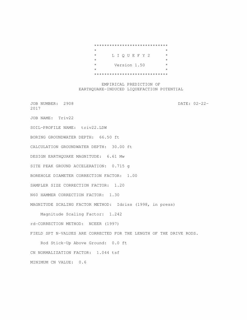
*****************************
* *
* L I Q U E F Y 2 *
* *
* Version 1.50 *
* *
*****************************
EMPIRICAL PREDICTION OF
EARTHQUAKE-INDUCED LIQUEFACTION POTENTIAL
JOB NUMBER: 2908 DATE: 02-22-
2017
JOB NAME: Triv22
SOIL-PROFILE NAME: triv22.LDW
BORING GROUNDWATER DEPTH: 66.50 ft
CALCULATION GROUNDWATER DEPTH: 30.00 ft
DESIGN EARTHQUAKE MAGNITUDE: 6.61 Mw
SITE PEAK GROUND ACCELERATION: 0.715 g
BOREHOLE DIAMETER CORRECTION FACTOR: 1.00
SAMPLER SIZE CORRECTION FACTOR: 1.20
N60 HAMMER CORRECTION FACTOR: 1.30
MAGNITUDE SCALING FACTOR METHOD: Idriss (1998, in press)
Magnitude Scaling Factor: 1.242
rd-CORRECTION METHOD: NCEER (1997)
FIELD SPT N-VALUES ARE CORRECTED FOR THE LENGTH OF THE DRIVE RODS.
Rod Stick-Up Above Ground: 0.0 ft
CN NORMALIZATION FACTOR: 1.044 tsf
MINIMUM CN VALUE: 0.6

------------------- -----------------------------
NCEER [1997] Method LIQUEFACTION ANALYSIS SUMMARY PAGE 1
------------------- -----------------------------
File Name: triv22.OUT
------------------------------------------------------------------------------
| CALC.| TOTAL| EFF. |FIELD | FC | | CORR.|LIQUE.| |INDUC.|LIQUE.
SOIL| DEPTH|STRESS|STRESS| N |DELTA| C |(N1)60|RESIST| r |STRESS|SAFETY
NO.| (ft) | (tsf)| (tsf)|(B/ft)|N1_60| N |(B/ft)| RATIO| d | RATIO|FACTOR
----+------+------+------+------+-----+-----+------+------+-----+------+------
1 | 0.25| 0.015| 0.015| 10 | ~ | * | * | * | * | * | **
1 | 0.75| 0.045| 0.045| 10 | ~ | * | * | * | * | * | **
1 | 1.25| 0.075| 0.075| 10 | ~ | * | * | * | * | * | **
1 | 1.75| 0.105| 0.105| 10 | ~ | * | * | * | * | * | **
1 | 2.25| 0.135| 0.135| 10 | ~ | * | * | * | * | * | **
1 | 2.75| 0.165| 0.165| 10 | ~ | * | * | * | * | * | **
1 | 3.25| 0.195| 0.195| 10 | ~ | * | * | * | * | * | **
1 | 3.75| 0.225| 0.225| 10 | ~ | * | * | * | * | * | **
1 | 4.25| 0.255| 0.255| 10 | ~ | * | * | * | * | * | **
1 | 4.75| 0.285| 0.285| 10 | ~ | * | * | * | * | * | **
1 | 5.25| 0.315| 0.315| 10 | ~ | * | * | * | * | * | **
1 | 5.75| 0.345| 0.345| 10 | ~ | * | * | * | * | * | **
1 | 6.25| 0.375| 0.375| 10 | ~ | * | * | * | * | * | **
1 | 6.75| 0.405| 0.405| 10 | ~ | * | * | * | * | * | **
1 | 7.25| 0.435| 0.435| 10 | ~ | * | * | * | * | * | **
1 | 7.75| 0.465| 0.465| 10 | ~ | * | * | * | * | * | **
1 | 8.25| 0.495| 0.495| 10 | ~ | * | * | * | * | * | **
1 | 8.75| 0.525| 0.525| 10 | ~ | * | * | * | * | * | **
1 | 9.25| 0.555| 0.555| 10 | ~ | * | * | * | * | * | **
1 | 9.75| 0.585| 0.585| 10 | ~ | * | * | * | * | * | **
1 | 10.25| 0.615| 0.615| 10 | ~ | * | * | * | * | * | **
1 | 10.75| 0.645| 0.645| 10 | ~ | * | * | * | * | * | **
1 | 11.25| 0.675| 0.675| 10 | ~ | * | * | * | * | * | **
1 | 11.75| 0.705| 0.705| 10 | ~ | * | * | * | * | * | **
1 | 12.25| 0.735| 0.735| 10 | ~ | * | * | * | * | * | **
1 | 12.75| 0.765| 0.765| 10 | ~ | * | * | * | * | * | **
1 | 13.25| 0.795| 0.795| 10 | ~ | * | * | * | * | * | **
1 | 13.75| 0.825| 0.825| 10 | ~ | * | * | * | * | * | **
1 | 14.25| 0.855| 0.855| 10 | ~ | * | * | * | * | * | **
1 | 14.75| 0.885| 0.885| 10 | ~ | * | * | * | * | * | **
1 | 15.25| 0.915| 0.915| 10 | ~ | * | * | * | * | * | **
1 | 15.75| 0.945| 0.945| 10 | ~ | * | * | * | * | * | **
1 | 16.25| 0.975| 0.975| 10 | ~ | * | * | * | * | * | **
1 | 16.75| 1.005| 1.005| 10 | ~ | * | * | * | * | * | **
1 | 17.25| 1.035| 1.035| 10 | ~ | * | * | * | * | * | **
1 | 17.75| 1.065| 1.065| 10 | ~ | * | * | * | * | * | **
1 | 18.25| 1.095| 1.095| 10 | ~ | * | * | * | * | * | **
1 | 18.75| 1.125| 1.125| 10 | ~ | * | * | * | * | * | **
1 | 19.25| 1.155| 1.155| 10 | ~ | * | * | * | * | * | **
1 | 19.75| 1.185| 1.185| 10 | ~ | * | * | * | * | * | **
1 | 20.25| 1.215| 1.215| 10 | ~ | * | * | * | * | * | **
1 | 20.75| 1.245| 1.245| 10 | ~ | * | * | * | * | * | **
1 | 21.25| 1.275| 1.275| 10 | ~ | * | * | * | * | * | **

------------------- -----------------------------
NCEER [1997] Method LIQUEFACTION ANALYSIS SUMMARY PAGE 2
------------------- -----------------------------
File Name: triv22.OUT
------------------------------------------------------------------------------
| CALC.| TOTAL| EFF. |FIELD | FC | | CORR.|LIQUE.| |INDUC.|LIQUE.
SOIL| DEPTH|STRESS|STRESS| N |DELTA| C |(N1)60|RESIST| r |STRESS|SAFETY
NO.| (ft) | (tsf)| (tsf)|(B/ft)|N1_60| N |(B/ft)| RATIO| d | RATIO|FACTOR
----+------+------+------+------+-----+-----+------+------+-----+------+------
1 | 21.75| 1.305| 1.305| 10 | ~ | * | * | * | * | * | **
1 | 22.25| 1.335| 1.335| 10 | ~ | * | * | * | * | * | **
1 | 22.75| 1.365| 1.365| 10 | ~ | * | * | * | * | * | **
1 | 23.25| 1.395| 1.395| 10 | ~ | * | * | * | * | * | **
1 | 23.75| 1.425| 1.425| 10 | ~ | * | * | * | * | * | **
1 | 24.25| 1.455| 1.455| 10 | ~ | * | * | * | * | * | **
1 | 24.75| 1.485| 1.485| 10 | ~ | * | * | * | * | * | **
1 | 25.25| 1.515| 1.515| 10 | ~ | * | * | * | * | * | **
1 | 25.75| 1.545| 1.545| 10 | ~ | * | * | * | * | * | **
1 | 26.25| 1.575| 1.575| 10 | ~ | * | * | * | * | * | **
1 | 26.75| 1.605| 1.605| 10 | ~ | * | * | * | * | * | **
1 | 27.25| 1.635| 1.635| 10 | ~ | * | * | * | * | * | **
1 | 27.75| 1.665| 1.665| 10 | ~ | * | * | * | * | * | **
1 | 28.25| 1.695| 1.695| 10 | ~ | * | * | * | * | * | **
1 | 28.75| 1.725| 1.725| 10 | ~ | * | * | * | * | * | **
1 | 29.25| 1.755| 1.755| 10 | ~ | * | * | * | * | * | **
1 | 29.75| 1.785| 1.785| 10 | ~ | * | * | * | * | * | **
2 | 30.25| 1.815| 1.807| 21 | 9.26|0.703| 32.3 |Infin |0.928| 0.433|NonLiq
2 | 30.75| 1.845| 1.822| 21 | 9.26|0.703| 32.3 |Infin |0.924| 0.435|NonLiq
2 | 31.25| 1.875| 1.836| 21 | 9.26|0.703| 32.3 |Infin |0.920| 0.437|NonLiq
2 | 31.75| 1.905| 1.850| 21 | 9.26|0.703| 32.3 |Infin |0.916| 0.438|NonLiq
2 | 32.25| 1.935| 1.865| 21 | 9.26|0.703| 32.3 |Infin |0.912| 0.440|NonLiq
2 | 32.75| 1.965| 1.879| 21 | 9.26|0.703| 32.3 |Infin |0.907| 0.441|NonLiq
2 | 33.25| 1.995| 1.894| 21 | 9.26|0.703| 32.3 |Infin |0.903| 0.442|NonLiq
2 | 33.75| 2.025| 1.908| 21 | 9.26|0.703| 32.3 |Infin |0.899| 0.444|NonLiq
2 | 34.25| 2.055| 1.922| 21 | 9.26|0.703| 32.3 |Infin |0.895| 0.445|NonLiq
2 | 34.75| 2.085| 1.937| 21 | 9.26|0.703| 32.3 |Infin |0.891| 0.446|NonLiq
2 | 35.25| 2.115| 1.951| 21 | 9.26|0.703| 32.3 |Infin |0.887| 0.447|NonLiq
2 | 35.75| 2.145| 1.966| 21 | 9.26|0.703| 32.3 |Infin |0.883| 0.448|NonLiq
2 | 36.25| 2.175| 1.980| 21 | 9.26|0.703| 32.3 |Infin |0.879| 0.449|NonLiq
2 | 36.75| 2.205| 1.994| 21 | 9.26|0.703| 32.3 |Infin |0.875| 0.450|NonLiq
2 | 37.25| 2.235| 2.009| 21 | 9.26|0.703| 32.3 |Infin |0.871| 0.450|NonLiq
2 | 37.75| 2.265| 2.023| 21 | 9.26|0.703| 32.3 |Infin |0.867| 0.451|NonLiq
3 | 38.25| 2.295| 2.038| 33 | 0.04|0.657| 33.9 |Infin |0.863| 0.452|NonLiq
3 | 38.75| 2.325| 2.052| 33 | 0.04|0.657| 33.9 |Infin |0.859| 0.452|NonLiq
3 | 39.25| 2.355| 2.066| 33 | 0.04|0.657| 33.9 |Infin |0.855| 0.453|NonLiq
3 | 39.75| 2.385| 2.081| 33 | 0.04|0.657| 33.9 |Infin |0.851| 0.453|NonLiq
3 | 40.25| 2.415| 2.095| 33 | 0.04|0.657| 33.9 |Infin |0.846| 0.453|NonLiq
3 | 40.75| 2.445| 2.110| 33 | 0.04|0.657| 33.9 |Infin |0.842| 0.454|NonLiq
3 | 41.25| 2.475| 2.124| 33 | 0.04|0.657| 33.9 |Infin |0.838| 0.454|NonLiq
3 | 41.75| 2.505| 2.138| 33 | 0.04|0.657| 33.9 |Infin |0.834| 0.454|NonLiq
4 | 42.25| 2.535| 2.153| 30 | ~ | ~ | ~ | ~ | ~ | ~ | ~~
4 | 42.75| 2.565| 2.167| 30 | ~ | ~ | ~ | ~ | ~ | ~ | ~~
4 | 43.25| 2.595| 2.182| 30 | ~ | ~ | ~ | ~ | ~ | ~ | ~~
------------------- -----------------------------

NCEER [1997] Method LIQUEFACTION ANALYSIS SUMMARY PAGE 3
------------------- -----------------------------
File Name: triv22.OUT
------------------------------------------------------------------------------
| CALC.| TOTAL| EFF. |FIELD | FC | | CORR.|LIQUE.| |INDUC.|LIQUE.
SOIL| DEPTH|STRESS|STRESS| N |DELTA| C |(N1)60|RESIST| r |STRESS|SAFETY
NO.| (ft) | (tsf)| (tsf)|(B/ft)|N1_60| N |(B/ft)| RATIO| d | RATIO|FACTOR
----+------+------+------+------+-----+-----+------+------+-----+------+------
4 | 43.75| 2.625| 2.196| 30 | ~ | ~ | ~ | ~ | ~ | ~ | ~~
4 | 44.25| 2.655| 2.210| 30 | ~ | ~ | ~ | ~ | ~ | ~ | ~~
4 | 44.75| 2.685| 2.225| 30 | ~ | ~ | ~ | ~ | ~ | ~ | ~~
4 | 45.25| 2.715| 2.239| 30 | ~ | ~ | ~ | ~ | ~ | ~ | ~~
4 | 45.75| 2.745| 2.254| 30 | ~ | ~ | ~ | ~ | ~ | ~ | ~~
4 | 46.25| 2.775| 2.268| 30 | ~ | ~ | ~ | ~ | ~ | ~ | ~~
4 | 46.75| 2.805| 2.282| 30 | ~ | ~ | ~ | ~ | ~ | ~ | ~~
4 | 47.25| 2.835| 2.297| 30 | ~ | ~ | ~ | ~ | ~ | ~ | ~~
4 | 47.75| 2.865| 2.311| 30 | ~ | ~ | ~ | ~ | ~ | ~ | ~~
5 | 48.25| 2.895| 2.326| 39 | 0.05|0.600| 36.5 |Infin |0.781| 0.452|NonLiq
5 | 48.75| 2.925| 2.340| 39 | 0.05|0.600| 36.5 |Infin |0.777| 0.452|NonLiq
5 | 49.25| 2.955| 2.354| 39 | 0.05|0.600| 36.5 |Infin |0.773| 0.451|NonLiq
5 | 49.75| 2.985| 2.369| 39 | 0.05|0.600| 36.5 |Infin |0.769| 0.450|NonLiq
5 | 50.25| 3.015| 2.383| 39 | 0.05|0.600| 36.5 |Infin |0.765| 0.450|NonLiq
5 | 50.75| 3.045| 2.398| 39 | 0.05|0.600| 36.5 |Infin |0.761| 0.449|NonLiq
5 | 51.25| 3.075| 2.412| 39 | 0.05|0.600| 36.5 |Infin |0.757| 0.448|NonLiq
5 | 51.75| 3.105| 2.426| 39 | 0.05|0.600| 36.5 |Infin |0.753| 0.448|NonLiq
5 | 52.25| 3.135| 2.441| 39 | 0.05|0.600| 36.5 |Infin |0.749| 0.447|NonLiq
5 | 52.75| 3.165| 2.455| 39 | 0.05|0.600| 36.5 |Infin |0.745| 0.446|NonLiq
5 | 53.25| 3.195| 2.470| 39 | 0.05|0.600| 36.5 |Infin |0.741| 0.445|NonLiq
5 | 53.75| 3.225| 2.484| 39 | 0.05|0.600| 36.5 |Infin |0.737| 0.444|NonLiq
5 | 54.25| 3.255| 2.498| 39 | 0.05|0.600| 36.5 |Infin |0.732| 0.444|NonLiq
5 | 54.75| 3.285| 2.513| 39 | 0.05|0.600| 36.5 |Infin |0.728| 0.443|NonLiq
5 | 55.25| 3.315| 2.527| 39 | 0.05|0.600| 36.5 |Infin |0.724| 0.442|NonLiq
5 | 55.75| 3.345| 2.542| 39 | 0.05|0.600| 36.5 |Infin |0.720| 0.441|NonLiq
5 | 56.25| 3.375| 2.556| 39 | 0.05|0.600| 36.5 |Infin |0.716| 0.440|NonLiq
5 | 56.75| 3.405| 2.570| 39 | 0.05|0.600| 36.5 |Infin |0.712| 0.438|NonLiq
5 | 57.25| 3.435| 2.585| 39 | 0.05|0.600| 36.5 |Infin |0.708| 0.437|NonLiq
5 | 57.75| 3.465| 2.599| 39 | 0.05|0.600| 36.5 |Infin |0.704| 0.436|NonLiq
5 | 58.25| 3.495| 2.614| 39 | 0.05|0.600| 36.5 |Infin |0.700| 0.435|NonLiq
5 | 58.75| 3.525| 2.628| 39 | 0.05|0.600| 36.5 |Infin |0.696| 0.434|NonLiq
5 | 59.25| 3.555| 2.642| 39 | 0.05|0.600| 36.5 |Infin |0.692| 0.433|NonLiq
5 | 59.75| 3.585| 2.657| 39 | 0.05|0.600| 36.5 |Infin |0.688| 0.431|NonLiq
5 | 60.25| 3.615| 2.671| 39 | 0.05|0.600| 36.5 |Infin |0.684| 0.430|NonLiq
5 | 60.75| 3.645| 2.686| 39 | 0.05|0.600| 36.5 |Infin |0.680| 0.429|NonLiq
5 | 61.25| 3.675| 2.700| 39 | 0.05|0.600| 36.5 |Infin |0.676| 0.427|NonLiq
5 | 61.75| 3.705| 2.714| 39 | 0.05|0.600| 36.5 |Infin |0.671| 0.426|NonLiq
5 | 62.25| 3.735| 2.729| 39 | 0.05|0.600| 36.5 |Infin |0.667| 0.425|NonLiq
5 | 62.75| 3.765| 2.743| 39 | 0.05|0.600| 36.5 |Infin |0.663| 0.423|NonLiq
5 | 63.25| 3.795| 2.758| 39 | 0.05|0.600| 36.5 |Infin |0.659| 0.422|NonLiq
5 | 63.75| 3.825| 2.772| 39 | 0.05|0.600| 36.5 |Infin |0.655| 0.420|NonLiq
5 | 64.25| 3.855| 2.786| 39 | 0.05|0.600| 36.5 |Infin |0.651| 0.419|NonLiq
5 | 64.75| 3.885| 2.801| 39 | 0.05|0.600| 36.5 |Infin |0.647| 0.417|NonLiq
5 | 65.25| 3.915| 2.815| 39 | 0.05|0.600| 36.5 |Infin |0.643| 0.416|NonLiq
------------------- -----------------------------
NCEER [1997] Method LIQUEFACTION ANALYSIS SUMMARY PAGE 4
------------------- -----------------------------
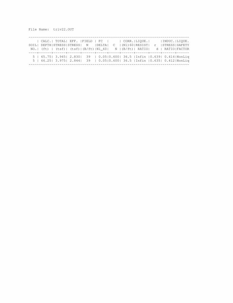
File Name: triv22.OUT
------------------------------------------------------------------------------
| CALC.| TOTAL| EFF. |FIELD | FC | | CORR.|LIQUE.| |INDUC.|LIQUE.
SOIL| DEPTH|STRESS|STRESS| N |DELTA| C |(N1)60|RESIST| r |STRESS|SAFETY
NO.| (ft) | (tsf)| (tsf)|(B/ft)|N1_60| N |(B/ft)| RATIO| d | RATIO|FACTOR
----+------+------+------+------+-----+-----+------+------+-----+------+------
5 | 65.75| 3.945| 2.830| 39 | 0.05|0.600| 36.5 |Infin |0.639| 0.414|NonLiq
5 | 66.25| 3.975| 2.844| 39 | 0.05|0.600| 36.5 |Infin |0.635| 0.412|NonLiq
~~~~~~~~~~~~~~~~~~~~~~~~~~~~~~~~~~~~~~~~~~~~~~~~~~~~~~~~~~~~~~~~~~~~~~~~~~~~~~

*****************************
* *
* L I Q U E F Y 2 *
* *
* Version 1.50 *
* *
*****************************
EMPIRICAL PREDICTION OF
EARTHQUAKE-INDUCED LIQUEFACTION POTENTIAL
JOB NUMBER: 2908 DATE: 02-22-
2017
JOB NAME: Triv210
SOIL-PROFILE NAME: triv210.LDW
BORING GROUNDWATER DEPTH: 66.50 ft
CALCULATION GROUNDWATER DEPTH: 30.00 ft
DESIGN EARTHQUAKE MAGNITUDE: 6.61 Mw
SITE PEAK GROUND ACCELERATION: 0.480 g
BOREHOLE DIAMETER CORRECTION FACTOR: 1.00
SAMPLER SIZE CORRECTION FACTOR: 1.20
N60 HAMMER CORRECTION FACTOR: 1.30
MAGNITUDE SCALING FACTOR METHOD: Idriss (1998, in press)
Magnitude Scaling Factor: 1.242
rd-CORRECTION METHOD: NCEER (1997)
FIELD SPT N-VALUES ARE CORRECTED FOR THE LENGTH OF THE DRIVE RODS.
Rod Stick-Up Above Ground: 0.0 ft
CN NORMALIZATION FACTOR: 1.044 tsf
MINIMUM CN VALUE: 0.6

------------------- -----------------------------
NCEER [1997] Method LIQUEFACTION ANALYSIS SUMMARY PAGE 1
------------------- -----------------------------
File Name: triv210.OUT
------------------------------------------------------------------------------
| CALC.| TOTAL| EFF. |FIELD | FC | | CORR.|LIQUE.| |INDUC.|LIQUE.
SOIL| DEPTH|STRESS|STRESS| N |DELTA| C |(N1)60|RESIST| r |STRESS|SAFETY
NO.| (ft) | (tsf)| (tsf)|(B/ft)|N1_60| N |(B/ft)| RATIO| d | RATIO|FACTOR
----+------+------+------+------+-----+-----+------+------+-----+------+------
1 | 0.25| 0.015| 0.015| 10 | ~ | * | * | * | * | * | **
1 | 0.75| 0.045| 0.045| 10 | ~ | * | * | * | * | * | **
1 | 1.25| 0.075| 0.075| 10 | ~ | * | * | * | * | * | **
1 | 1.75| 0.105| 0.105| 10 | ~ | * | * | * | * | * | **
1 | 2.25| 0.135| 0.135| 10 | ~ | * | * | * | * | * | **
1 | 2.75| 0.165| 0.165| 10 | ~ | * | * | * | * | * | **
1 | 3.25| 0.195| 0.195| 10 | ~ | * | * | * | * | * | **
1 | 3.75| 0.225| 0.225| 10 | ~ | * | * | * | * | * | **
1 | 4.25| 0.255| 0.255| 10 | ~ | * | * | * | * | * | **
1 | 4.75| 0.285| 0.285| 10 | ~ | * | * | * | * | * | **
1 | 5.25| 0.315| 0.315| 10 | ~ | * | * | * | * | * | **
1 | 5.75| 0.345| 0.345| 10 | ~ | * | * | * | * | * | **
1 | 6.25| 0.375| 0.375| 10 | ~ | * | * | * | * | * | **
1 | 6.75| 0.405| 0.405| 10 | ~ | * | * | * | * | * | **
1 | 7.25| 0.435| 0.435| 10 | ~ | * | * | * | * | * | **
1 | 7.75| 0.465| 0.465| 10 | ~ | * | * | * | * | * | **
1 | 8.25| 0.495| 0.495| 10 | ~ | * | * | * | * | * | **
1 | 8.75| 0.525| 0.525| 10 | ~ | * | * | * | * | * | **
1 | 9.25| 0.555| 0.555| 10 | ~ | * | * | * | * | * | **
1 | 9.75| 0.585| 0.585| 10 | ~ | * | * | * | * | * | **
1 | 10.25| 0.615| 0.615| 10 | ~ | * | * | * | * | * | **
1 | 10.75| 0.645| 0.645| 10 | ~ | * | * | * | * | * | **
1 | 11.25| 0.675| 0.675| 10 | ~ | * | * | * | * | * | **
1 | 11.75| 0.705| 0.705| 10 | ~ | * | * | * | * | * | **
1 | 12.25| 0.735| 0.735| 10 | ~ | * | * | * | * | * | **
1 | 12.75| 0.765| 0.765| 10 | ~ | * | * | * | * | * | **
1 | 13.25| 0.795| 0.795| 10 | ~ | * | * | * | * | * | **
1 | 13.75| 0.825| 0.825| 10 | ~ | * | * | * | * | * | **
1 | 14.25| 0.855| 0.855| 10 | ~ | * | * | * | * | * | **
1 | 14.75| 0.885| 0.885| 10 | ~ | * | * | * | * | * | **
1 | 15.25| 0.915| 0.915| 10 | ~ | * | * | * | * | * | **
1 | 15.75| 0.945| 0.945| 10 | ~ | * | * | * | * | * | **
1 | 16.25| 0.975| 0.975| 10 | ~ | * | * | * | * | * | **
1 | 16.75| 1.005| 1.005| 10 | ~ | * | * | * | * | * | **
1 | 17.25| 1.035| 1.035| 10 | ~ | * | * | * | * | * | **
1 | 17.75| 1.065| 1.065| 10 | ~ | * | * | * | * | * | **
1 | 18.25| 1.095| 1.095| 10 | ~ | * | * | * | * | * | **
1 | 18.75| 1.125| 1.125| 10 | ~ | * | * | * | * | * | **
1 | 19.25| 1.155| 1.155| 10 | ~ | * | * | * | * | * | **
1 | 19.75| 1.185| 1.185| 10 | ~ | * | * | * | * | * | **
1 | 20.25| 1.215| 1.215| 10 | ~ | * | * | * | * | * | **
1 | 20.75| 1.245| 1.245| 10 | ~ | * | * | * | * | * | **
1 | 21.25| 1.275| 1.275| 10 | ~ | * | * | * | * | * | **

------------------- -----------------------------
NCEER [1997] Method LIQUEFACTION ANALYSIS SUMMARY PAGE 2
------------------- -----------------------------
File Name: triv210.OUT
------------------------------------------------------------------------------
| CALC.| TOTAL| EFF. |FIELD | FC | | CORR.|LIQUE.| |INDUC.|LIQUE.
SOIL| DEPTH|STRESS|STRESS| N |DELTA| C |(N1)60|RESIST| r |STRESS|SAFETY
NO.| (ft) | (tsf)| (tsf)|(B/ft)|N1_60| N |(B/ft)| RATIO| d | RATIO|FACTOR
----+------+------+------+------+-----+-----+------+------+-----+------+------
1 | 21.75| 1.305| 1.305| 10 | ~ | * | * | * | * | * | **
1 | 22.25| 1.335| 1.335| 10 | ~ | * | * | * | * | * | **
1 | 22.75| 1.365| 1.365| 10 | ~ | * | * | * | * | * | **
1 | 23.25| 1.395| 1.395| 10 | ~ | * | * | * | * | * | **
1 | 23.75| 1.425| 1.425| 10 | ~ | * | * | * | * | * | **
1 | 24.25| 1.455| 1.455| 10 | ~ | * | * | * | * | * | **
1 | 24.75| 1.485| 1.485| 10 | ~ | * | * | * | * | * | **
1 | 25.25| 1.515| 1.515| 10 | ~ | * | * | * | * | * | **
1 | 25.75| 1.545| 1.545| 10 | ~ | * | * | * | * | * | **
1 | 26.25| 1.575| 1.575| 10 | ~ | * | * | * | * | * | **
1 | 26.75| 1.605| 1.605| 10 | ~ | * | * | * | * | * | **
1 | 27.25| 1.635| 1.635| 10 | ~ | * | * | * | * | * | **
1 | 27.75| 1.665| 1.665| 10 | ~ | * | * | * | * | * | **
1 | 28.25| 1.695| 1.695| 10 | ~ | * | * | * | * | * | **
1 | 28.75| 1.725| 1.725| 10 | ~ | * | * | * | * | * | **
1 | 29.25| 1.755| 1.755| 10 | ~ | * | * | * | * | * | **
1 | 29.75| 1.785| 1.785| 10 | ~ | * | * | * | * | * | **
2 | 30.25| 1.815| 1.807| 21 | 9.26|0.703| 32.3 |Infin |0.928| 0.291|NonLiq
2 | 30.75| 1.845| 1.822| 21 | 9.26|0.703| 32.3 |Infin |0.924| 0.292|NonLiq
2 | 31.25| 1.875| 1.836| 21 | 9.26|0.703| 32.3 |Infin |0.920| 0.293|NonLiq
2 | 31.75| 1.905| 1.850| 21 | 9.26|0.703| 32.3 |Infin |0.916| 0.294|NonLiq
2 | 32.25| 1.935| 1.865| 21 | 9.26|0.703| 32.3 |Infin |0.912| 0.295|NonLiq
2 | 32.75| 1.965| 1.879| 21 | 9.26|0.703| 32.3 |Infin |0.907| 0.296|NonLiq
2 | 33.25| 1.995| 1.894| 21 | 9.26|0.703| 32.3 |Infin |0.903| 0.297|NonLiq
2 | 33.75| 2.025| 1.908| 21 | 9.26|0.703| 32.3 |Infin |0.899| 0.298|NonLiq
2 | 34.25| 2.055| 1.922| 21 | 9.26|0.703| 32.3 |Infin |0.895| 0.299|NonLiq
2 | 34.75| 2.085| 1.937| 21 | 9.26|0.703| 32.3 |Infin |0.891| 0.299|NonLiq
2 | 35.25| 2.115| 1.951| 21 | 9.26|0.703| 32.3 |Infin |0.887| 0.300|NonLiq
2 | 35.75| 2.145| 1.966| 21 | 9.26|0.703| 32.3 |Infin |0.883| 0.301|NonLiq
2 | 36.25| 2.175| 1.980| 21 | 9.26|0.703| 32.3 |Infin |0.879| 0.301|NonLiq
2 | 36.75| 2.205| 1.994| 21 | 9.26|0.703| 32.3 |Infin |0.875| 0.302|NonLiq
2 | 37.25| 2.235| 2.009| 21 | 9.26|0.703| 32.3 |Infin |0.871| 0.302|NonLiq
2 | 37.75| 2.265| 2.023| 21 | 9.26|0.703| 32.3 |Infin |0.867| 0.303|NonLiq
3 | 38.25| 2.295| 2.038| 33 | 0.04|0.657| 33.9 |Infin |0.863| 0.303|NonLiq
3 | 38.75| 2.325| 2.052| 33 | 0.04|0.657| 33.9 |Infin |0.859| 0.304|NonLiq
3 | 39.25| 2.355| 2.066| 33 | 0.04|0.657| 33.9 |Infin |0.855| 0.304|NonLiq
3 | 39.75| 2.385| 2.081| 33 | 0.04|0.657| 33.9 |Infin |0.851| 0.304|NonLiq
3 | 40.25| 2.415| 2.095| 33 | 0.04|0.657| 33.9 |Infin |0.846| 0.304|NonLiq
3 | 40.75| 2.445| 2.110| 33 | 0.04|0.657| 33.9 |Infin |0.842| 0.305|NonLiq
3 | 41.25| 2.475| 2.124| 33 | 0.04|0.657| 33.9 |Infin |0.838| 0.305|NonLiq
3 | 41.75| 2.505| 2.138| 33 | 0.04|0.657| 33.9 |Infin |0.834| 0.305|NonLiq
4 | 42.25| 2.535| 2.153| 30 | ~ | ~ | ~ | ~ | ~ | ~ | ~~
4 | 42.75| 2.565| 2.167| 30 | ~ | ~ | ~ | ~ | ~ | ~ | ~~
4 | 43.25| 2.595| 2.182| 30 | ~ | ~ | ~ | ~ | ~ | ~ | ~~
------------------- -----------------------------

NCEER [1997] Method LIQUEFACTION ANALYSIS SUMMARY PAGE 3
------------------- -----------------------------
File Name: triv210.OUT
------------------------------------------------------------------------------
| CALC.| TOTAL| EFF. |FIELD | FC | | CORR.|LIQUE.| |INDUC.|LIQUE.
SOIL| DEPTH|STRESS|STRESS| N |DELTA| C |(N1)60|RESIST| r |STRESS|SAFETY
NO.| (ft) | (tsf)| (tsf)|(B/ft)|N1_60| N |(B/ft)| RATIO| d | RATIO|FACTOR
----+------+------+------+------+-----+-----+------+------+-----+------+------
4 | 43.75| 2.625| 2.196| 30 | ~ | ~ | ~ | ~ | ~ | ~ | ~~
4 | 44.25| 2.655| 2.210| 30 | ~ | ~ | ~ | ~ | ~ | ~ | ~~
4 | 44.75| 2.685| 2.225| 30 | ~ | ~ | ~ | ~ | ~ | ~ | ~~
4 | 45.25| 2.715| 2.239| 30 | ~ | ~ | ~ | ~ | ~ | ~ | ~~
4 | 45.75| 2.745| 2.254| 30 | ~ | ~ | ~ | ~ | ~ | ~ | ~~
4 | 46.25| 2.775| 2.268| 30 | ~ | ~ | ~ | ~ | ~ | ~ | ~~
4 | 46.75| 2.805| 2.282| 30 | ~ | ~ | ~ | ~ | ~ | ~ | ~~
4 | 47.25| 2.835| 2.297| 30 | ~ | ~ | ~ | ~ | ~ | ~ | ~~
4 | 47.75| 2.865| 2.311| 30 | ~ | ~ | ~ | ~ | ~ | ~ | ~~
5 | 48.25| 2.895| 2.326| 39 | 0.05|0.600| 36.5 |Infin |0.781| 0.303|NonLiq
5 | 48.75| 2.925| 2.340| 39 | 0.05|0.600| 36.5 |Infin |0.777| 0.303|NonLiq
5 | 49.25| 2.955| 2.354| 39 | 0.05|0.600| 36.5 |Infin |0.773| 0.303|NonLiq
5 | 49.75| 2.985| 2.369| 39 | 0.05|0.600| 36.5 |Infin |0.769| 0.302|NonLiq
5 | 50.25| 3.015| 2.383| 39 | 0.05|0.600| 36.5 |Infin |0.765| 0.302|NonLiq
5 | 50.75| 3.045| 2.398| 39 | 0.05|0.600| 36.5 |Infin |0.761| 0.302|NonLiq
5 | 51.25| 3.075| 2.412| 39 | 0.05|0.600| 36.5 |Infin |0.757| 0.301|NonLiq
5 | 51.75| 3.105| 2.426| 39 | 0.05|0.600| 36.5 |Infin |0.753| 0.301|NonLiq
5 | 52.25| 3.135| 2.441| 39 | 0.05|0.600| 36.5 |Infin |0.749| 0.300|NonLiq
5 | 52.75| 3.165| 2.455| 39 | 0.05|0.600| 36.5 |Infin |0.745| 0.300|NonLiq
5 | 53.25| 3.195| 2.470| 39 | 0.05|0.600| 36.5 |Infin |0.741| 0.299|NonLiq
5 | 53.75| 3.225| 2.484| 39 | 0.05|0.600| 36.5 |Infin |0.737| 0.298|NonLiq
5 | 54.25| 3.255| 2.498| 39 | 0.05|0.600| 36.5 |Infin |0.732| 0.298|NonLiq
5 | 54.75| 3.285| 2.513| 39 | 0.05|0.600| 36.5 |Infin |0.728| 0.297|NonLiq
5 | 55.25| 3.315| 2.527| 39 | 0.05|0.600| 36.5 |Infin |0.724| 0.296|NonLiq
5 | 55.75| 3.345| 2.542| 39 | 0.05|0.600| 36.5 |Infin |0.720| 0.296|NonLiq
5 | 56.25| 3.375| 2.556| 39 | 0.05|0.600| 36.5 |Infin |0.716| 0.295|NonLiq
5 | 56.75| 3.405| 2.570| 39 | 0.05|0.600| 36.5 |Infin |0.712| 0.294|NonLiq
5 | 57.25| 3.435| 2.585| 39 | 0.05|0.600| 36.5 |Infin |0.708| 0.294|NonLiq
5 | 57.75| 3.465| 2.599| 39 | 0.05|0.600| 36.5 |Infin |0.704| 0.293|NonLiq
5 | 58.25| 3.495| 2.614| 39 | 0.05|0.600| 36.5 |Infin |0.700| 0.292|NonLiq
5 | 58.75| 3.525| 2.628| 39 | 0.05|0.600| 36.5 |Infin |0.696| 0.291|NonLiq
5 | 59.25| 3.555| 2.642| 39 | 0.05|0.600| 36.5 |Infin |0.692| 0.290|NonLiq
5 | 59.75| 3.585| 2.657| 39 | 0.05|0.600| 36.5 |Infin |0.688| 0.290|NonLiq
5 | 60.25| 3.615| 2.671| 39 | 0.05|0.600| 36.5 |Infin |0.684| 0.289|NonLiq
5 | 60.75| 3.645| 2.686| 39 | 0.05|0.600| 36.5 |Infin |0.680| 0.288|NonLiq
5 | 61.25| 3.675| 2.700| 39 | 0.05|0.600| 36.5 |Infin |0.676| 0.287|NonLiq
5 | 61.75| 3.705| 2.714| 39 | 0.05|0.600| 36.5 |Infin |0.671| 0.286|NonLiq
5 | 62.25| 3.735| 2.729| 39 | 0.05|0.600| 36.5 |Infin |0.667| 0.285|NonLiq
5 | 62.75| 3.765| 2.743| 39 | 0.05|0.600| 36.5 |Infin |0.663| 0.284|NonLiq
5 | 63.25| 3.795| 2.758| 39 | 0.05|0.600| 36.5 |Infin |0.659| 0.283|NonLiq
5 | 63.75| 3.825| 2.772| 39 | 0.05|0.600| 36.5 |Infin |0.655| 0.282|NonLiq
5 | 64.25| 3.855| 2.786| 39 | 0.05|0.600| 36.5 |Infin |0.651| 0.281|NonLiq
5 | 64.75| 3.885| 2.801| 39 | 0.05|0.600| 36.5 |Infin |0.647| 0.280|NonLiq
5 | 65.25| 3.915| 2.815| 39 | 0.05|0.600| 36.5 |Infin |0.643| 0.279|NonLiq
------------------- -----------------------------
NCEER [1997] Method LIQUEFACTION ANALYSIS SUMMARY PAGE 4
------------------- -----------------------------

File Name: triv210.OUT
------------------------------------------------------------------------------
| CALC.| TOTAL| EFF. |FIELD | FC | | CORR.|LIQUE.| |INDUC.|LIQUE.
SOIL| DEPTH|STRESS|STRESS| N |DELTA| C |(N1)60|RESIST| r |STRESS|SAFETY
NO.| (ft) | (tsf)| (tsf)|(B/ft)|N1_60| N |(B/ft)| RATIO| d | RATIO|FACTOR
----+------+------+------+------+-----+-----+------+------+-----+------+------
5 | 65.75| 3.945| 2.830| 39 | 0.05|0.600| 36.5 |Infin |0.639| 0.278|NonLiq
5 | 66.25| 3.975| 2.844| 39 | 0.05|0.600| 36.5 |Infin |0.635| 0.277|NonLiq
~~~~~~~~~~~~~~~~~~~~~~~~~~~~~~~~~~~~~~~~~~~~~~~~~~~~~~~~~~~~~~~~~~~~~~~~~~~~~~

*****************************
* *
* L I Q U E F Y 2 *
* *
* Version 1.50 *
* *
*****************************
EMPIRICAL PREDICTION OF
EARTHQUAKE-INDUCED LIQUEFACTION POTENTIAL
JOB NUMBER: 2908 DATE: 02-22-
2017
JOB NAME: Triv32
SOIL-PROFILE NAME: triv32.LDW
BORING GROUNDWATER DEPTH: 66.50 ft
CALCULATION GROUNDWATER DEPTH: 30.00 ft
DESIGN EARTHQUAKE MAGNITUDE: 6.61 Mw
SITE PEAK GROUND ACCELERATION: 0.715 g
BOREHOLE DIAMETER CORRECTION FACTOR: 1.00
SAMPLER SIZE CORRECTION FACTOR: 1.20
N60 HAMMER CORRECTION FACTOR: 1.30
MAGNITUDE SCALING FACTOR METHOD: Idriss (1998, in press)
Magnitude Scaling Factor: 1.242
rd-CORRECTION METHOD: NCEER (1997)
FIELD SPT N-VALUES ARE CORRECTED FOR THE LENGTH OF THE DRIVE RODS.
Rod Stick-Up Above Ground: 0.0 ft
CN NORMALIZATION FACTOR: 1.044 tsf
MINIMUM CN VALUE: 0.6

------------------- -----------------------------
NCEER [1997] Method LIQUEFACTION ANALYSIS SUMMARY PAGE 1
------------------- -----------------------------
File Name: triv32.OUT
------------------------------------------------------------------------------
| CALC.| TOTAL| EFF. |FIELD | FC | | CORR.|LIQUE.| |INDUC.|LIQUE.
SOIL| DEPTH|STRESS|STRESS| N |DELTA| C |(N1)60|RESIST| r |STRESS|SAFETY
NO.| (ft) | (tsf)| (tsf)|(B/ft)|N1_60| N |(B/ft)| RATIO| d | RATIO|FACTOR
----+------+------+------+------+-----+-----+------+------+-----+------+------
1 | 0.25| 0.015| 0.015| 10 | ~ | * | * | * | * | * | **
1 | 0.75| 0.045| 0.045| 10 | ~ | * | * | * | * | * | **
1 | 1.25| 0.075| 0.075| 10 | ~ | * | * | * | * | * | **
1 | 1.75| 0.105| 0.105| 10 | ~ | * | * | * | * | * | **
1 | 2.25| 0.135| 0.135| 10 | ~ | * | * | * | * | * | **
1 | 2.75| 0.165| 0.165| 10 | ~ | * | * | * | * | * | **
1 | 3.25| 0.195| 0.195| 10 | ~ | * | * | * | * | * | **
1 | 3.75| 0.225| 0.225| 10 | ~ | * | * | * | * | * | **
1 | 4.25| 0.255| 0.255| 10 | ~ | * | * | * | * | * | **
1 | 4.75| 0.285| 0.285| 10 | ~ | * | * | * | * | * | **
1 | 5.25| 0.315| 0.315| 10 | ~ | * | * | * | * | * | **
1 | 5.75| 0.345| 0.345| 10 | ~ | * | * | * | * | * | **
1 | 6.25| 0.375| 0.375| 10 | ~ | * | * | * | * | * | **
1 | 6.75| 0.405| 0.405| 10 | ~ | * | * | * | * | * | **
1 | 7.25| 0.435| 0.435| 10 | ~ | * | * | * | * | * | **
1 | 7.75| 0.465| 0.465| 10 | ~ | * | * | * | * | * | **
1 | 8.25| 0.495| 0.495| 10 | ~ | * | * | * | * | * | **
1 | 8.75| 0.525| 0.525| 10 | ~ | * | * | * | * | * | **
1 | 9.25| 0.555| 0.555| 10 | ~ | * | * | * | * | * | **
1 | 9.75| 0.585| 0.585| 10 | ~ | * | * | * | * | * | **
1 | 10.25| 0.615| 0.615| 10 | ~ | * | * | * | * | * | **
1 | 10.75| 0.645| 0.645| 10 | ~ | * | * | * | * | * | **
1 | 11.25| 0.675| 0.675| 10 | ~ | * | * | * | * | * | **
1 | 11.75| 0.705| 0.705| 10 | ~ | * | * | * | * | * | **
1 | 12.25| 0.735| 0.735| 10 | ~ | * | * | * | * | * | **
1 | 12.75| 0.765| 0.765| 10 | ~ | * | * | * | * | * | **
1 | 13.25| 0.795| 0.795| 10 | ~ | * | * | * | * | * | **
1 | 13.75| 0.825| 0.825| 10 | ~ | * | * | * | * | * | **
1 | 14.25| 0.855| 0.855| 10 | ~ | * | * | * | * | * | **
1 | 14.75| 0.885| 0.885| 10 | ~ | * | * | * | * | * | **
1 | 15.25| 0.915| 0.915| 10 | ~ | * | * | * | * | * | **
1 | 15.75| 0.945| 0.945| 10 | ~ | * | * | * | * | * | **
1 | 16.25| 0.975| 0.975| 10 | ~ | * | * | * | * | * | **
1 | 16.75| 1.005| 1.005| 10 | ~ | * | * | * | * | * | **
1 | 17.25| 1.035| 1.035| 10 | ~ | * | * | * | * | * | **
1 | 17.75| 1.065| 1.065| 10 | ~ | * | * | * | * | * | **
1 | 18.25| 1.095| 1.095| 10 | ~ | * | * | * | * | * | **
1 | 18.75| 1.125| 1.125| 10 | ~ | * | * | * | * | * | **
1 | 19.25| 1.155| 1.155| 10 | ~ | * | * | * | * | * | **
1 | 19.75| 1.185| 1.185| 10 | ~ | * | * | * | * | * | **
1 | 20.25| 1.215| 1.215| 10 | ~ | * | * | * | * | * | **
1 | 20.75| 1.245| 1.245| 10 | ~ | * | * | * | * | * | **
1 | 21.25| 1.275| 1.275| 10 | ~ | * | * | * | * | * | **

------------------- -----------------------------
NCEER [1997] Method LIQUEFACTION ANALYSIS SUMMARY PAGE 2
------------------- -----------------------------
File Name: triv32.OUT
------------------------------------------------------------------------------
| CALC.| TOTAL| EFF. |FIELD | FC | | CORR.|LIQUE.| |INDUC.|LIQUE.
SOIL| DEPTH|STRESS|STRESS| N |DELTA| C |(N1)60|RESIST| r |STRESS|SAFETY
NO.| (ft) | (tsf)| (tsf)|(B/ft)|N1_60| N |(B/ft)| RATIO| d | RATIO|FACTOR
----+------+------+------+------+-----+-----+------+------+-----+------+------
1 | 21.75| 1.305| 1.305| 10 | ~ | * | * | * | * | * | **
1 | 22.25| 1.335| 1.335| 10 | ~ | * | * | * | * | * | **
1 | 22.75| 1.365| 1.365| 10 | ~ | * | * | * | * | * | **
1 | 23.25| 1.395| 1.395| 10 | ~ | * | * | * | * | * | **
1 | 23.75| 1.425| 1.425| 10 | ~ | * | * | * | * | * | **
1 | 24.25| 1.455| 1.455| 10 | ~ | * | * | * | * | * | **
1 | 24.75| 1.485| 1.485| 10 | ~ | * | * | * | * | * | **
1 | 25.25| 1.515| 1.515| 10 | ~ | * | * | * | * | * | **
1 | 25.75| 1.545| 1.545| 10 | ~ | * | * | * | * | * | **
1 | 26.25| 1.575| 1.575| 10 | ~ | * | * | * | * | * | **
1 | 26.75| 1.605| 1.605| 10 | ~ | * | * | * | * | * | **
1 | 27.25| 1.635| 1.635| 10 | ~ | * | * | * | * | * | **
1 | 27.75| 1.665| 1.665| 10 | ~ | * | * | * | * | * | **
1 | 28.25| 1.695| 1.695| 10 | ~ | * | * | * | * | * | **
1 | 28.75| 1.725| 1.725| 10 | ~ | * | * | * | * | * | **
1 | 29.25| 1.755| 1.755| 10 | ~ | * | * | * | * | * | **
1 | 29.75| 1.785| 1.785| 10 | ~ | * | * | * | * | * | **
2 | 30.25| 1.815| 1.807| 68 | 0.10|0.758| 80.6 |Infin |0.928| 0.433|NonLiq
2 | 30.75| 1.845| 1.822| 68 | 0.10|0.758| 80.6 |Infin |0.924| 0.435|NonLiq
2 | 31.25| 1.875| 1.836| 68 | 0.10|0.758| 80.6 |Infin |0.920| 0.437|NonLiq
2 | 31.75| 1.905| 1.850| 68 | 0.10|0.758| 80.6 |Infin |0.916| 0.438|NonLiq
3 | 32.25| 1.935| 1.865| 34 | 0.05|0.703| 37.3 |Infin |0.912| 0.440|NonLiq
3 | 32.75| 1.965| 1.879| 34 | 0.05|0.703| 37.3 |Infin |0.907| 0.441|NonLiq
3 | 33.25| 1.995| 1.894| 34 | 0.05|0.703| 37.3 |Infin |0.903| 0.442|NonLiq
3 | 33.75| 2.025| 1.908| 34 | 0.05|0.703| 37.3 |Infin |0.899| 0.444|NonLiq
3 | 34.25| 2.055| 1.922| 34 | 0.05|0.703| 37.3 |Infin |0.895| 0.445|NonLiq
3 | 34.75| 2.085| 1.937| 34 | 0.05|0.703| 37.3 |Infin |0.891| 0.446|NonLiq
3 | 35.25| 2.115| 1.951| 34 | 0.05|0.703| 37.3 |Infin |0.887| 0.447|NonLiq
3 | 35.75| 2.145| 1.966| 34 | 0.05|0.703| 37.3 |Infin |0.883| 0.448|NonLiq
3 | 36.25| 2.175| 1.980| 34 | 0.05|0.703| 37.3 |Infin |0.879| 0.449|NonLiq
3 | 36.75| 2.205| 1.994| 34 | 0.05|0.703| 37.3 |Infin |0.875| 0.450|NonLiq
3 | 37.25| 2.235| 2.009| 34 | 0.05|0.703| 37.3 |Infin |0.871| 0.450|NonLiq
4 | 37.75| 2.265| 2.023| 45 | 0.06|0.657| 46.2 |Infin |0.867| 0.451|NonLiq
4 | 38.25| 2.295| 2.038| 45 | 0.06|0.657| 46.2 |Infin |0.863| 0.452|NonLiq
4 | 38.75| 2.325| 2.052| 45 | 0.06|0.657| 46.2 |Infin |0.859| 0.452|NonLiq
4 | 39.25| 2.355| 2.066| 45 | 0.06|0.657| 46.2 |Infin |0.855| 0.453|NonLiq
4 | 39.75| 2.385| 2.081| 45 | 0.06|0.657| 46.2 |Infin |0.851| 0.453|NonLiq
4 | 40.25| 2.415| 2.095| 45 | 0.06|0.657| 46.2 |Infin |0.846| 0.453|NonLiq
4 | 40.75| 2.445| 2.110| 45 | 0.06|0.657| 46.2 |Infin |0.842| 0.454|NonLiq
4 | 41.25| 2.475| 2.124| 45 | 0.06|0.657| 46.2 |Infin |0.838| 0.454|NonLiq
4 | 41.75| 2.505| 2.138| 45 | 0.06|0.657| 46.2 |Infin |0.834| 0.454|NonLiq
4 | 42.25| 2.535| 2.153| 45 | 0.06|0.657| 46.2 |Infin |0.830| 0.454|NonLiq
5 | 42.75| 2.565| 2.167| 34 | 0.04|0.620| 32.9 |Infin |0.826| 0.454|NonLiq
5 | 43.25| 2.595| 2.182| 34 | 0.04|0.620| 32.9 |Infin |0.822| 0.454|NonLiq
------------------- -----------------------------
NCEER [1997] Method LIQUEFACTION ANALYSIS SUMMARY PAGE 3

------------------- -----------------------------
File Name: triv32.OUT
------------------------------------------------------------------------------
| CALC.| TOTAL| EFF. |FIELD | FC | | CORR.|LIQUE.| |INDUC.|LIQUE.
SOIL| DEPTH|STRESS|STRESS| N |DELTA| C |(N1)60|RESIST| r |STRESS|SAFETY
NO.| (ft) | (tsf)| (tsf)|(B/ft)|N1_60| N |(B/ft)| RATIO| d | RATIO|FACTOR
----+------+------+------+------+-----+-----+------+------+-----+------+------
5 | 43.75| 2.625| 2.196| 34 | 0.04|0.620| 32.9 |Infin |0.818| 0.454|NonLiq
5 | 44.25| 2.655| 2.210| 34 | 0.04|0.620| 32.9 |Infin |0.814| 0.454|NonLiq
5 | 44.75| 2.685| 2.225| 34 | 0.04|0.620| 32.9 |Infin |0.810| 0.454|NonLiq
5 | 45.25| 2.715| 2.239| 34 | 0.04|0.620| 32.9 |Infin |0.806| 0.454|NonLiq
5 | 45.75| 2.745| 2.254| 34 | 0.04|0.620| 32.9 |Infin |0.802| 0.454|NonLiq
5 | 46.25| 2.775| 2.268| 34 | 0.04|0.620| 32.9 |Infin |0.798| 0.454|NonLiq
6 | 46.75| 2.805| 2.282| 58 | 0.07|0.600| 54.4 |Infin |0.794| 0.453|NonLiq
6 | 47.25| 2.835| 2.297| 58 | 0.07|0.600| 54.4 |Infin |0.789| 0.453|NonLiq
6 | 47.75| 2.865| 2.311| 58 | 0.07|0.600| 54.4 |Infin |0.785| 0.452|NonLiq
6 | 48.25| 2.895| 2.326| 58 | 0.07|0.600| 54.4 |Infin |0.781| 0.452|NonLiq
6 | 48.75| 2.925| 2.340| 58 | 0.07|0.600| 54.4 |Infin |0.777| 0.452|NonLiq
6 | 49.25| 2.955| 2.354| 58 | 0.07|0.600| 54.4 |Infin |0.773| 0.451|NonLiq
6 | 49.75| 2.985| 2.369| 58 | 0.07|0.600| 54.4 |Infin |0.769| 0.450|NonLiq
6 | 50.25| 3.015| 2.383| 58 | 0.07|0.600| 54.4 |Infin |0.765| 0.450|NonLiq
6 | 50.75| 3.045| 2.398| 58 | 0.07|0.600| 54.4 |Infin |0.761| 0.449|NonLiq
6 | 51.25| 3.075| 2.412| 58 | 0.07|0.600| 54.4 |Infin |0.757| 0.448|NonLiq
6 | 51.75| 3.105| 2.426| 58 | 0.07|0.600| 54.4 |Infin |0.753| 0.448|NonLiq
6 | 52.25| 3.135| 2.441| 58 | 0.07|0.600| 54.4 |Infin |0.749| 0.447|NonLiq
6 | 52.75| 3.165| 2.455| 58 | 0.07|0.600| 54.4 |Infin |0.745| 0.446|NonLiq
7 | 53.25| 3.195| 2.470| 56 | 0.06|0.600| 52.5 |Infin |0.741| 0.445|NonLiq
7 | 53.75| 3.225| 2.484| 56 | 0.06|0.600| 52.5 |Infin |0.737| 0.444|NonLiq
7 | 54.25| 3.255| 2.498| 56 | 0.06|0.600| 52.5 |Infin |0.732| 0.444|NonLiq
7 | 54.75| 3.285| 2.513| 56 | 0.06|0.600| 52.5 |Infin |0.728| 0.443|NonLiq
7 | 55.25| 3.315| 2.527| 56 | 0.06|0.600| 52.5 |Infin |0.724| 0.442|NonLiq
7 | 55.75| 3.345| 2.542| 56 | 0.06|0.600| 52.5 |Infin |0.720| 0.441|NonLiq
7 | 56.25| 3.375| 2.556| 56 | 0.06|0.600| 52.5 |Infin |0.716| 0.440|NonLiq
7 | 56.75| 3.405| 2.570| 56 | 0.06|0.600| 52.5 |Infin |0.712| 0.438|NonLiq
7 | 57.25| 3.435| 2.585| 56 | 0.06|0.600| 52.5 |Infin |0.708| 0.437|NonLiq
7 | 57.75| 3.465| 2.599| 56 | 0.06|0.600| 52.5 |Infin |0.704| 0.436|NonLiq
7 | 58.25| 3.495| 2.614| 56 | 0.06|0.600| 52.5 |Infin |0.700| 0.435|NonLiq
7 | 58.75| 3.525| 2.628| 56 | 0.06|0.600| 52.5 |Infin |0.696| 0.434|NonLiq
7 | 59.25| 3.555| 2.642| 56 | 0.06|0.600| 52.5 |Infin |0.692| 0.433|NonLiq
7 | 59.75| 3.585| 2.657| 56 | 0.06|0.600| 52.5 |Infin |0.688| 0.431|NonLiq
7 | 60.25| 3.615| 2.671| 56 | 0.06|0.600| 52.5 |Infin |0.684| 0.430|NonLiq
7 | 60.75| 3.645| 2.686| 56 | 0.06|0.600| 52.5 |Infin |0.680| 0.429|NonLiq
7 | 61.25| 3.675| 2.700| 56 | 0.06|0.600| 52.5 |Infin |0.676| 0.427|NonLiq
7 | 61.75| 3.705| 2.714| 56 | 0.06|0.600| 52.5 |Infin |0.671| 0.426|NonLiq
7 | 62.25| 3.735| 2.729| 56 | 0.06|0.600| 52.5 |Infin |0.667| 0.425|NonLiq
7 | 62.75| 3.765| 2.743| 56 | 0.06|0.600| 52.5 |Infin |0.663| 0.423|NonLiq
7 | 63.25| 3.795| 2.758| 56 | 0.06|0.600| 52.5 |Infin |0.659| 0.422|NonLiq
7 | 63.75| 3.825| 2.772| 56 | 0.06|0.600| 52.5 |Infin |0.655| 0.420|NonLiq
7 | 64.25| 3.855| 2.786| 56 | 0.06|0.600| 52.5 |Infin |0.651| 0.419|NonLiq
7 | 64.75| 3.885| 2.801| 56 | 0.06|0.600| 52.5 |Infin |0.647| 0.417|NonLiq
7 | 65.25| 3.915| 2.815| 56 | 0.06|0.600| 52.5 |Infin |0.643| 0.416|NonLiq
------------------- -----------------------------
NCEER [1997] Method LIQUEFACTION ANALYSIS SUMMARY PAGE 4
------------------- -----------------------------
File Name: triv32.OUT

------------------------------------------------------------------------------
| CALC.| TOTAL| EFF. |FIELD | FC | | CORR.|LIQUE.| |INDUC.|LIQUE.
SOIL| DEPTH|STRESS|STRESS| N |DELTA| C |(N1)60|RESIST| r |STRESS|SAFETY
NO.| (ft) | (tsf)| (tsf)|(B/ft)|N1_60| N |(B/ft)| RATIO| d | RATIO|FACTOR
----+------+------+------+------+-----+-----+------+------+-----+------+------
7 | 65.75| 3.945| 2.830| 56 | 0.06|0.600| 52.5 |Infin |0.639| 0.414|NonLiq
7 | 66.25| 3.975| 2.844| 56 | 0.06|0.600| 52.5 |Infin |0.635| 0.412|NonLiq
~~~~~~~~~~~~~~~~~~~~~~~~~~~~~~~~~~~~~~~~~~~~~~~~~~~~~~~~~~~~~~~~~~~~~~~~~~~~~~

*****************************
* *
* L I Q U E F Y 2 *
* *
* Version 1.50 *
* *
*****************************
EMPIRICAL PREDICTION OF
EARTHQUAKE-INDUCED LIQUEFACTION POTENTIAL
JOB NUMBER: 2908 DATE: 02-22-
2017
JOB NAME: Triv310
SOIL-PROFILE NAME: triv310.LDW
BORING GROUNDWATER DEPTH: 66.50 ft
CALCULATION GROUNDWATER DEPTH: 30.00 ft
DESIGN EARTHQUAKE MAGNITUDE: 6.61 Mw
SITE PEAK GROUND ACCELERATION: 0.480 g
BOREHOLE DIAMETER CORRECTION FACTOR: 1.00
SAMPLER SIZE CORRECTION FACTOR: 1.20
N60 HAMMER CORRECTION FACTOR: 1.30
MAGNITUDE SCALING FACTOR METHOD: Idriss (1998, in press)
Magnitude Scaling Factor: 1.242
rd-CORRECTION METHOD: NCEER (1997)
FIELD SPT N-VALUES ARE CORRECTED FOR THE LENGTH OF THE DRIVE RODS.
Rod Stick-Up Above Ground: 0.0 ft
CN NORMALIZATION FACTOR: 1.044 tsf
MINIMUM CN VALUE: 0.6

------------------- -----------------------------
NCEER [1997] Method LIQUEFACTION ANALYSIS SUMMARY PAGE 1
------------------- -----------------------------
File Name: triv310.OUT
------------------------------------------------------------------------------
| CALC.| TOTAL| EFF. |FIELD | FC | | CORR.|LIQUE.| |INDUC.|LIQUE.
SOIL| DEPTH|STRESS|STRESS| N |DELTA| C |(N1)60|RESIST| r |STRESS|SAFETY
NO.| (ft) | (tsf)| (tsf)|(B/ft)|N1_60| N |(B/ft)| RATIO| d | RATIO|FACTOR
----+------+------+------+------+-----+-----+------+------+-----+------+------
1 | 0.25| 0.015| 0.015| 10 | ~ | * | * | * | * | * | **
1 | 0.75| 0.045| 0.045| 10 | ~ | * | * | * | * | * | **
1 | 1.25| 0.075| 0.075| 10 | ~ | * | * | * | * | * | **
1 | 1.75| 0.105| 0.105| 10 | ~ | * | * | * | * | * | **
1 | 2.25| 0.135| 0.135| 10 | ~ | * | * | * | * | * | **
1 | 2.75| 0.165| 0.165| 10 | ~ | * | * | * | * | * | **
1 | 3.25| 0.195| 0.195| 10 | ~ | * | * | * | * | * | **
1 | 3.75| 0.225| 0.225| 10 | ~ | * | * | * | * | * | **
1 | 4.25| 0.255| 0.255| 10 | ~ | * | * | * | * | * | **
1 | 4.75| 0.285| 0.285| 10 | ~ | * | * | * | * | * | **
1 | 5.25| 0.315| 0.315| 10 | ~ | * | * | * | * | * | **
1 | 5.75| 0.345| 0.345| 10 | ~ | * | * | * | * | * | **
1 | 6.25| 0.375| 0.375| 10 | ~ | * | * | * | * | * | **
1 | 6.75| 0.405| 0.405| 10 | ~ | * | * | * | * | * | **
1 | 7.25| 0.435| 0.435| 10 | ~ | * | * | * | * | * | **
1 | 7.75| 0.465| 0.465| 10 | ~ | * | * | * | * | * | **
1 | 8.25| 0.495| 0.495| 10 | ~ | * | * | * | * | * | **
1 | 8.75| 0.525| 0.525| 10 | ~ | * | * | * | * | * | **
1 | 9.25| 0.555| 0.555| 10 | ~ | * | * | * | * | * | **
1 | 9.75| 0.585| 0.585| 10 | ~ | * | * | * | * | * | **
1 | 10.25| 0.615| 0.615| 10 | ~ | * | * | * | * | * | **
1 | 10.75| 0.645| 0.645| 10 | ~ | * | * | * | * | * | **
1 | 11.25| 0.675| 0.675| 10 | ~ | * | * | * | * | * | **
1 | 11.75| 0.705| 0.705| 10 | ~ | * | * | * | * | * | **
1 | 12.25| 0.735| 0.735| 10 | ~ | * | * | * | * | * | **
1 | 12.75| 0.765| 0.765| 10 | ~ | * | * | * | * | * | **
1 | 13.25| 0.795| 0.795| 10 | ~ | * | * | * | * | * | **
1 | 13.75| 0.825| 0.825| 10 | ~ | * | * | * | * | * | **
1 | 14.25| 0.855| 0.855| 10 | ~ | * | * | * | * | * | **
1 | 14.75| 0.885| 0.885| 10 | ~ | * | * | * | * | * | **
1 | 15.25| 0.915| 0.915| 10 | ~ | * | * | * | * | * | **
1 | 15.75| 0.945| 0.945| 10 | ~ | * | * | * | * | * | **
1 | 16.25| 0.975| 0.975| 10 | ~ | * | * | * | * | * | **
1 | 16.75| 1.005| 1.005| 10 | ~ | * | * | * | * | * | **
1 | 17.25| 1.035| 1.035| 10 | ~ | * | * | * | * | * | **
1 | 17.75| 1.065| 1.065| 10 | ~ | * | * | * | * | * | **
1 | 18.25| 1.095| 1.095| 10 | ~ | * | * | * | * | * | **
1 | 18.75| 1.125| 1.125| 10 | ~ | * | * | * | * | * | **
1 | 19.25| 1.155| 1.155| 10 | ~ | * | * | * | * | * | **
1 | 19.75| 1.185| 1.185| 10 | ~ | * | * | * | * | * | **
1 | 20.25| 1.215| 1.215| 10 | ~ | * | * | * | * | * | **
1 | 20.75| 1.245| 1.245| 10 | ~ | * | * | * | * | * | **
1 | 21.25| 1.275| 1.275| 10 | ~ | * | * | * | * | * | **

------------------- -----------------------------
NCEER [1997] Method LIQUEFACTION ANALYSIS SUMMARY PAGE 2
------------------- -----------------------------
File Name: triv310.OUT
------------------------------------------------------------------------------
| CALC.| TOTAL| EFF. |FIELD | FC | | CORR.|LIQUE.| |INDUC.|LIQUE.
SOIL| DEPTH|STRESS|STRESS| N |DELTA| C |(N1)60|RESIST| r |STRESS|SAFETY
NO.| (ft) | (tsf)| (tsf)|(B/ft)|N1_60| N |(B/ft)| RATIO| d | RATIO|FACTOR
----+------+------+------+------+-----+-----+------+------+-----+------+------
1 | 21.75| 1.305| 1.305| 10 | ~ | * | * | * | * | * | **
1 | 22.25| 1.335| 1.335| 10 | ~ | * | * | * | * | * | **
1 | 22.75| 1.365| 1.365| 10 | ~ | * | * | * | * | * | **
1 | 23.25| 1.395| 1.395| 10 | ~ | * | * | * | * | * | **
1 | 23.75| 1.425| 1.425| 10 | ~ | * | * | * | * | * | **
1 | 24.25| 1.455| 1.455| 10 | ~ | * | * | * | * | * | **
1 | 24.75| 1.485| 1.485| 10 | ~ | * | * | * | * | * | **
1 | 25.25| 1.515| 1.515| 10 | ~ | * | * | * | * | * | **
1 | 25.75| 1.545| 1.545| 10 | ~ | * | * | * | * | * | **
1 | 26.25| 1.575| 1.575| 10 | ~ | * | * | * | * | * | **
1 | 26.75| 1.605| 1.605| 10 | ~ | * | * | * | * | * | **
1 | 27.25| 1.635| 1.635| 10 | ~ | * | * | * | * | * | **
1 | 27.75| 1.665| 1.665| 10 | ~ | * | * | * | * | * | **
1 | 28.25| 1.695| 1.695| 10 | ~ | * | * | * | * | * | **
1 | 28.75| 1.725| 1.725| 10 | ~ | * | * | * | * | * | **
1 | 29.25| 1.755| 1.755| 10 | ~ | * | * | * | * | * | **
1 | 29.75| 1.785| 1.785| 10 | ~ | * | * | * | * | * | **
2 | 30.25| 1.815| 1.807| 68 | 0.10|0.758| 80.6 |Infin |0.928| 0.291|NonLiq
2 | 30.75| 1.845| 1.822| 68 | 0.10|0.758| 80.6 |Infin |0.924| 0.292|NonLiq
2 | 31.25| 1.875| 1.836| 68 | 0.10|0.758| 80.6 |Infin |0.920| 0.293|NonLiq
2 | 31.75| 1.905| 1.850| 68 | 0.10|0.758| 80.6 |Infin |0.916| 0.294|NonLiq
3 | 32.25| 1.935| 1.865| 34 | 0.05|0.703| 37.3 |Infin |0.912| 0.295|NonLiq
3 | 32.75| 1.965| 1.879| 34 | 0.05|0.703| 37.3 |Infin |0.907| 0.296|NonLiq
3 | 33.25| 1.995| 1.894| 34 | 0.05|0.703| 37.3 |Infin |0.903| 0.297|NonLiq
3 | 33.75| 2.025| 1.908| 34 | 0.05|0.703| 37.3 |Infin |0.899| 0.298|NonLiq
3 | 34.25| 2.055| 1.922| 34 | 0.05|0.703| 37.3 |Infin |0.895| 0.299|NonLiq
3 | 34.75| 2.085| 1.937| 34 | 0.05|0.703| 37.3 |Infin |0.891| 0.299|NonLiq
3 | 35.25| 2.115| 1.951| 34 | 0.05|0.703| 37.3 |Infin |0.887| 0.300|NonLiq
3 | 35.75| 2.145| 1.966| 34 | 0.05|0.703| 37.3 |Infin |0.883| 0.301|NonLiq
3 | 36.25| 2.175| 1.980| 34 | 0.05|0.703| 37.3 |Infin |0.879| 0.301|NonLiq
3 | 36.75| 2.205| 1.994| 34 | 0.05|0.703| 37.3 |Infin |0.875| 0.302|NonLiq
3 | 37.25| 2.235| 2.009| 34 | 0.05|0.703| 37.3 |Infin |0.871| 0.302|NonLiq
4 | 37.75| 2.265| 2.023| 45 | 0.06|0.657| 46.2 |Infin |0.867| 0.303|NonLiq
4 | 38.25| 2.295| 2.038| 45 | 0.06|0.657| 46.2 |Infin |0.863| 0.303|NonLiq
4 | 38.75| 2.325| 2.052| 45 | 0.06|0.657| 46.2 |Infin |0.859| 0.304|NonLiq
4 | 39.25| 2.355| 2.066| 45 | 0.06|0.657| 46.2 |Infin |0.855| 0.304|NonLiq
4 | 39.75| 2.385| 2.081| 45 | 0.06|0.657| 46.2 |Infin |0.851| 0.304|NonLiq
4 | 40.25| 2.415| 2.095| 45 | 0.06|0.657| 46.2 |Infin |0.846| 0.304|NonLiq
4 | 40.75| 2.445| 2.110| 45 | 0.06|0.657| 46.2 |Infin |0.842| 0.305|NonLiq
4 | 41.25| 2.475| 2.124| 45 | 0.06|0.657| 46.2 |Infin |0.838| 0.305|NonLiq
4 | 41.75| 2.505| 2.138| 45 | 0.06|0.657| 46.2 |Infin |0.834| 0.305|NonLiq
4 | 42.25| 2.535| 2.153| 45 | 0.06|0.657| 46.2 |Infin |0.830| 0.305|NonLiq
5 | 42.75| 2.565| 2.167| 34 | 0.04|0.620| 32.9 |Infin |0.826| 0.305|NonLiq
5 | 43.25| 2.595| 2.182| 34 | 0.04|0.620| 32.9 |Infin |0.822| 0.305|NonLiq
------------------- -----------------------------
NCEER [1997] Method LIQUEFACTION ANALYSIS SUMMARY PAGE 3

------------------- -----------------------------
File Name: triv310.OUT
------------------------------------------------------------------------------
| CALC.| TOTAL| EFF. |FIELD | FC | | CORR.|LIQUE.| |INDUC.|LIQUE.
SOIL| DEPTH|STRESS|STRESS| N |DELTA| C |(N1)60|RESIST| r |STRESS|SAFETY
NO.| (ft) | (tsf)| (tsf)|(B/ft)|N1_60| N |(B/ft)| RATIO| d | RATIO|FACTOR
----+------+------+------+------+-----+-----+------+------+-----+------+------
5 | 43.75| 2.625| 2.196| 34 | 0.04|0.620| 32.9 |Infin |0.818| 0.305|NonLiq
5 | 44.25| 2.655| 2.210| 34 | 0.04|0.620| 32.9 |Infin |0.814| 0.305|NonLiq
5 | 44.75| 2.685| 2.225| 34 | 0.04|0.620| 32.9 |Infin |0.810| 0.305|NonLiq
5 | 45.25| 2.715| 2.239| 34 | 0.04|0.620| 32.9 |Infin |0.806| 0.305|NonLiq
5 | 45.75| 2.745| 2.254| 34 | 0.04|0.620| 32.9 |Infin |0.802| 0.305|NonLiq
5 | 46.25| 2.775| 2.268| 34 | 0.04|0.620| 32.9 |Infin |0.798| 0.304|NonLiq
6 | 46.75| 2.805| 2.282| 58 | 0.07|0.600| 54.4 |Infin |0.794| 0.304|NonLiq
6 | 47.25| 2.835| 2.297| 58 | 0.07|0.600| 54.4 |Infin |0.789| 0.304|NonLiq
6 | 47.75| 2.865| 2.311| 58 | 0.07|0.600| 54.4 |Infin |0.785| 0.304|NonLiq
6 | 48.25| 2.895| 2.326| 58 | 0.07|0.600| 54.4 |Infin |0.781| 0.303|NonLiq
6 | 48.75| 2.925| 2.340| 58 | 0.07|0.600| 54.4 |Infin |0.777| 0.303|NonLiq
6 | 49.25| 2.955| 2.354| 58 | 0.07|0.600| 54.4 |Infin |0.773| 0.303|NonLiq
6 | 49.75| 2.985| 2.369| 58 | 0.07|0.600| 54.4 |Infin |0.769| 0.302|NonLiq
6 | 50.25| 3.015| 2.383| 58 | 0.07|0.600| 54.4 |Infin |0.765| 0.302|NonLiq
6 | 50.75| 3.045| 2.398| 58 | 0.07|0.600| 54.4 |Infin |0.761| 0.302|NonLiq
6 | 51.25| 3.075| 2.412| 58 | 0.07|0.600| 54.4 |Infin |0.757| 0.301|NonLiq
6 | 51.75| 3.105| 2.426| 58 | 0.07|0.600| 54.4 |Infin |0.753| 0.301|NonLiq
6 | 52.25| 3.135| 2.441| 58 | 0.07|0.600| 54.4 |Infin |0.749| 0.300|NonLiq
6 | 52.75| 3.165| 2.455| 58 | 0.07|0.600| 54.4 |Infin |0.745| 0.300|NonLiq
7 | 53.25| 3.195| 2.470| 56 | 0.06|0.600| 52.5 |Infin |0.741| 0.299|NonLiq
7 | 53.75| 3.225| 2.484| 56 | 0.06|0.600| 52.5 |Infin |0.737| 0.298|NonLiq
7 | 54.25| 3.255| 2.498| 56 | 0.06|0.600| 52.5 |Infin |0.732| 0.298|NonLiq
7 | 54.75| 3.285| 2.513| 56 | 0.06|0.600| 52.5 |Infin |0.728| 0.297|NonLiq
7 | 55.25| 3.315| 2.527| 56 | 0.06|0.600| 52.5 |Infin |0.724| 0.296|NonLiq
7 | 55.75| 3.345| 2.542| 56 | 0.06|0.600| 52.5 |Infin |0.720| 0.296|NonLiq
7 | 56.25| 3.375| 2.556| 56 | 0.06|0.600| 52.5 |Infin |0.716| 0.295|NonLiq
7 | 56.75| 3.405| 2.570| 56 | 0.06|0.600| 52.5 |Infin |0.712| 0.294|NonLiq
7 | 57.25| 3.435| 2.585| 56 | 0.06|0.600| 52.5 |Infin |0.708| 0.294|NonLiq
7 | 57.75| 3.465| 2.599| 56 | 0.06|0.600| 52.5 |Infin |0.704| 0.293|NonLiq
7 | 58.25| 3.495| 2.614| 56 | 0.06|0.600| 52.5 |Infin |0.700| 0.292|NonLiq
7 | 58.75| 3.525| 2.628| 56 | 0.06|0.600| 52.5 |Infin |0.696| 0.291|NonLiq
7 | 59.25| 3.555| 2.642| 56 | 0.06|0.600| 52.5 |Infin |0.692| 0.290|NonLiq
7 | 59.75| 3.585| 2.657| 56 | 0.06|0.600| 52.5 |Infin |0.688| 0.290|NonLiq
7 | 60.25| 3.615| 2.671| 56 | 0.06|0.600| 52.5 |Infin |0.684| 0.289|NonLiq
7 | 60.75| 3.645| 2.686| 56 | 0.06|0.600| 52.5 |Infin |0.680| 0.288|NonLiq
7 | 61.25| 3.675| 2.700| 56 | 0.06|0.600| 52.5 |Infin |0.676| 0.287|NonLiq
7 | 61.75| 3.705| 2.714| 56 | 0.06|0.600| 52.5 |Infin |0.671| 0.286|NonLiq
7 | 62.25| 3.735| 2.729| 56 | 0.06|0.600| 52.5 |Infin |0.667| 0.285|NonLiq
7 | 62.75| 3.765| 2.743| 56 | 0.06|0.600| 52.5 |Infin |0.663| 0.284|NonLiq
7 | 63.25| 3.795| 2.758| 56 | 0.06|0.600| 52.5 |Infin |0.659| 0.283|NonLiq
7 | 63.75| 3.825| 2.772| 56 | 0.06|0.600| 52.5 |Infin |0.655| 0.282|NonLiq
7 | 64.25| 3.855| 2.786| 56 | 0.06|0.600| 52.5 |Infin |0.651| 0.281|NonLiq
7 | 64.75| 3.885| 2.801| 56 | 0.06|0.600| 52.5 |Infin |0.647| 0.280|NonLiq
7 | 65.25| 3.915| 2.815| 56 | 0.06|0.600| 52.5 |Infin |0.643| 0.279|NonLiq
------------------- -----------------------------
NCEER [1997] Method LIQUEFACTION ANALYSIS SUMMARY PAGE 4
------------------- -----------------------------
File Name: triv310.OUT

------------------------------------------------------------------------------
| CALC.| TOTAL| EFF. |FIELD | FC | | CORR.|LIQUE.| |INDUC.|LIQUE.
SOIL| DEPTH|STRESS|STRESS| N |DELTA| C |(N1)60|RESIST| r |STRESS|SAFETY
NO.| (ft) | (tsf)| (tsf)|(B/ft)|N1_60| N |(B/ft)| RATIO| d | RATIO|FACTOR
----+------+------+------+------+-----+-----+------+------+-----+------+------
7 | 65.75| 3.945| 2.830| 56 | 0.06|0.600| 52.5 |Infin |0.639| 0.278|NonLiq
7 | 66.25| 3.975| 2.844| 56 | 0.06|0.600| 52.5 |Infin |0.635| 0.277|NonLiq
~~~~~~~~~~~~~~~~~~~~~~~~~~~~~~~~~~~~~~~~~~~~~~~~~~~~~~~~~~~~~~~~~~~~~~~~~~~~~~
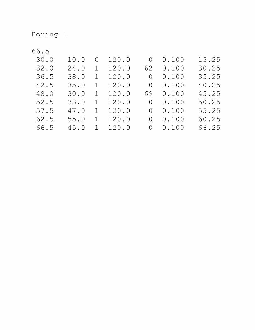
Boring 1
66.5
30.0 10.0 0 120.0 0 0.100 15.25
32.0 24.0 1 120.0 62 0.100 30.25
36.5 38.0 1 120.0 0 0.100 35.25
42.5 35.0 1 120.0 0 0.100 40.25
48.0 30.0 1 120.0 69 0.100 45.25
52.5 33.0 1 120.0 0 0.100 50.25
57.5 47.0 1 120.0 0 0.100 55.25
62.5 55.0 1 120.0 0 0.100 60.25
66.5 45.0 1 120.0 0 0.100 66.25
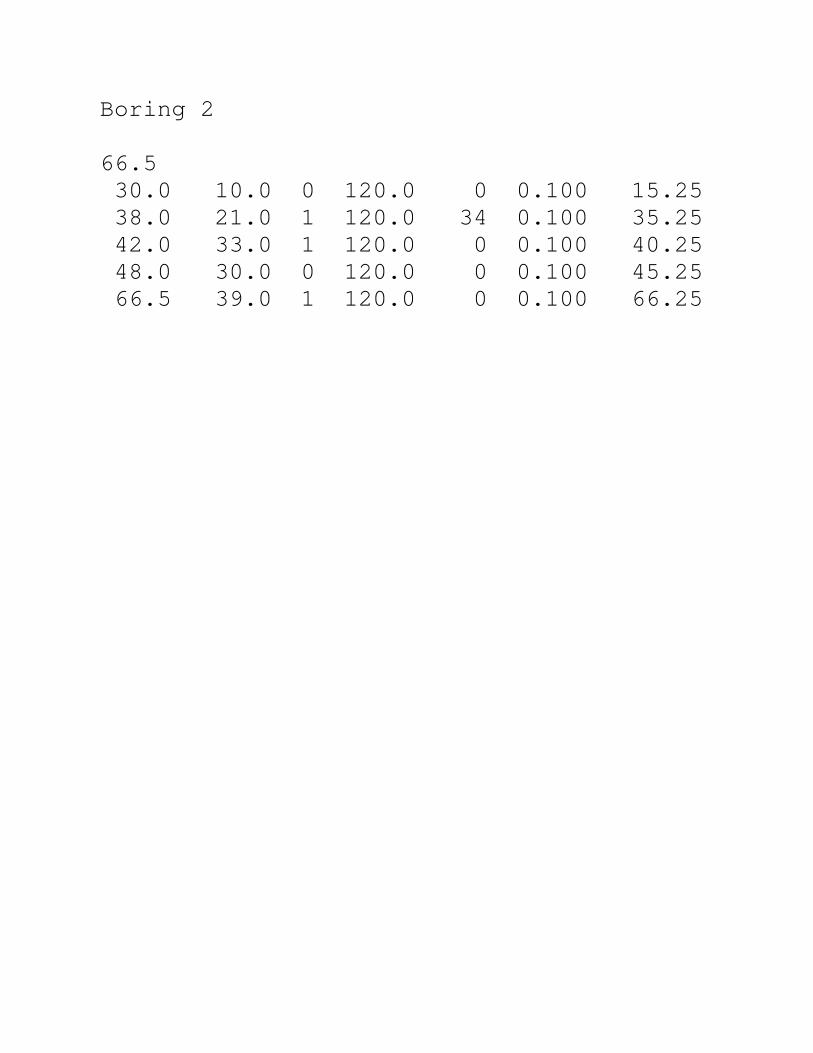
Boring 2
66.5
30.0 10.0 0 120.0 0 0.100 15.25
38.0 21.0 1 120.0 34 0.100 35.25
42.0 33.0 1 120.0 0 0.100 40.25
48.0 30.0 0 120.0 0 0.100 45.25
66.5 39.0 1 120.0 0 0.100 66.25

Boring 3
66.5
30.0 10.0 0 120.0 0 0.100 15.25
32.0 68.0 1 120.0 0 0.100 30.25
37.5 34.0 1 120.0 0 0.100 35.25
42.5 45.0 1 120.0 0 0.100 40.25
46.5 34.0 1 120.0 0 0.100 45.25
53.0 58.0 1 120.0 0 0.100 50.25
66.5 56.0 1 120.0 0 0.100 66.25
Top Related