


Languages
Pages
Legal


Se
cure
Com
mun
icat
ions
Prod
uct B
roch
ure
| 02.
00R&S®M3SR Series4100 HF Broadband SystemFlexible and modular multi line radio system
Series4100_HFBB_bro_en_5214-1243-12_v0200.indd 1 15.07.2013 15:36:30

2
Series4100_HFBB_bro_en_5214-1243-12_v0200.indd 2 15.07.2013 15:36:37

Rohde & Schwarz R&S®M3SR Series4100 HF Broadband System 3
ContentsR&S®M3SR Series4100 HF Broadband System ..........4 ❙ HF broadband system – a future-ready investment
System configuration of the HF broadband system ..............................................................................6 ❙ Broadband block ❙ R&S®FK2950antennatriplexer,R&S®FK2960 antenna diplexer
❙ Local control ❙ Flexible, logical allocation of connected receivers/excitersandpoweramplifiers
❙ ¸FK4192/¸FK4194 passive HF power combiners ❙ R&S®GV4190D power management unit
Water cooling equipment .............................................10 ❙ System components
R&S®KL4192M heat exchanger ...................................12 ❙ Brief description ❙ Key facts ❙ Electrical design ❙ Mechanical design
R&S®KL4193M water cooling set ...............................14 ❙ Brief description ❙ Key facts ❙ Electrical design ❙ Mechanical design
R&S®ZW4193M water-cooled dummy load (1+2+1 kW).....................................................................16 ❙ Brief description ❙ Key facts ❙ Electrical design ❙ Mechanical design
R&S®ZW4194M water-cooled dummy load (4 kW) .......................................................18 ❙ Brief description ❙ Key facts ❙ Electrical design ❙ Mechanical design
R&S®GU4190 overheat watch panel, R&S®GU4190A remote alarm unit ..............................20 ❙ Brief description ❙ Key facts ❙ Electrical design ❙ Application
Product overview ...........................................................22 ❙ HF broadband system ❙ Water cooling equipment for HF broadband systems
Series4100_HFBB_bro_en_5214-1243-12_v0200.indd 3 15.07.2013 15:36:40

4
R&S®M3SR Series4100 HF Broadband SystemAt a glance
The HF broadband system is a flexible and modular multi line radio system for the HF frequency range. The applications range from navy ships to shore radio stations with up to 32 radio lines. The system’s excellent scalability makes it suitable for use on board a wide range of ships, from Corvette-class vessels to aircraft carriers as well as for shore stations.The system offers the full range of R&S®M3SR Series4100 modulation modes and waveforms, from simple SSB operation and ALE to EPM (ECCM) radio line. Intelligent radio line management provides flexible and dynamic allocation of transmit power, from a few watts to several kilowatts, to support a variety of missions.
Example: HF broadband system with one four-line block.
Series4100_HFBB_bro_en_5214-1243-12_v0200.indd 4 15.07.2013 15:36:46

Rohde & Schwarz R&S®M3SR Series4100 HF Broadband System 5
Example rack layout
HF broadband system – a future-ready investmentThe system is based on the principle of combining ship-board HF radio lines with the help of highly linear, passive line couplers and then transmitting the combined signal using a broadband antenna system. The system covers the entire HF frequency band from 2 MHz to 30 MHz and consists of separate broadband antennas, each covering a subband. A diplexer or triplexer selects each antenna segment.
The antenna system contains no switched elements. The broadband capability of the antennas eliminates the need for antenna tuning units. Since only passive components such as couplers and filters are used, the result is a low-maintenance system with superior reliability.
Additionally installed:¸KL4193M
Equipment rack C
¸FK2950
¸FK4194
¸ZW4193M
Connection panel water
¸ZW4194M
¸GU4190
Additionally installed:¸KL4192M
Equipment rack A
¸VK4190
¸FK4194
¸GV4190D
¸GX4100D
¸IN4190
¸FK4192
¸IN4190
¸VK4190
Connection panel water
Additionally installed:¸KL4192M
Equipment rack B
Connection panel water
¸VK4190
¸GX4100D
¸GX4100D
¸IN4190
¸FK4192
¸IN4190
¸VK4190
Power distribution
Power distribution
Power distribution
Power distribution
Power distribution
¸BV4190
¸BV4190
¸BV4190
¸BV4190
Series4100_HFBB_bro_en_5214-1243-12_v0200.indd 5 15.07.2013 15:36:47

6
A broadband system can consist of up to 32 radio lines which are connected to a broadband antenna system. The channel spacing between adjacent radio lines can be ad-justed to a minimum of one percent. The individual radio lines can be occupied by any of the waveforms supported by the R&S®M3SR Series4100 including: ❙ Voice (SSB, AM, FM) ❙ Radio teletype (RATT) ❙ Modem (e.g. STANAG 4285, STANAG 4539) ❙ Automatic link establishment (ALE-2G/3G) ❙ Tactical data links (e.g. LINK11, LINK22) ❙ EPM (ECCM) paths
Broadband blockThe broadband block is a modular component of the HF broadband system. It consists of four 1000 W transceiver systems, the appropriate passive, highly linear power com-biner and the R&S®GV4190D power management unit (PMU). The PMU allocates the radio signals of each of the connected receivers/exciters to one, two or four power amplifiers at the small signal level. It also permanently monitors status reports from system components such as amplifiers, power supplies, power combiners and filters. In the case of coherent power addition, the PMU also en-sures that the signals to be added are in phase.
System configuration ofthe HF broadbandsystem
The HF broadband system can be expanded to support up to 32 radio lines
HF lines LAN connectionMonitoring of combiners
Medium band
High band
Low band
Terminal,control system
R&S®FK4194combiner
R&S®FK2950antenna triplexer
Broadbandblock(4 × 1 kW)
Broadbandblock(4 × 1 kW)
Broadbandblock(4 × 1 kW)
Broadbandblock(4 × 1 kW)
Broadbandblock(4 × 1 kW)
Broadbandblock(4 × 1 kW)
Broadbandblock(4 × 1 kW)
Broadbandblock(4 × 1 kW)
R&S®FK4194combiner
R&S®FK4194combiner
R&S®FK4194combiner
R&S®FK4194combiner
R&S®FK4194combiner
R&S®FK4194combiner
PMU PMU PMU PMU PMU PMU PMU PMU
Series4100_HFBB_bro_en_5214-1243-12_v0200.indd 6 15.07.2013 15:36:47

Rohde & Schwarz R&S®M3SR Series4100 HF Broadband System 7
R&S®FK41944 kW combiner
R&S®FK41922 kW combiner
R&S®VK4190power amplifier
R&S®VK4190power amplifier
R&S®GX4100exciter
R&S®GX4100exciter
R&S®GX4100exciterf2 f3 f4
Connection to RXantenna multicoupler
AF lines tointercom system
HF lines Monitoring of combinersControl bus system
R&S®FK41922 kW combiner
R&S®VK4190power amplifier
R&S®VK4190power amplifier
R&S®GX4100exciterf1
R&S®GV4190 PMU
To broadband antenna system
Broadband block: 4 × 1 kW radio lines and power management unit
R&S®FK2950 antenna triplexer, R&S®FK2960 antenna diplexerThe HF broadband antenna system may consist of an R&S®FK2950 antenna tri plexer and a three-section broad-band antenna.
A two-section antenna (e.g. twin fan) and an R&S®FK2960 antenna diplexer may be used for smaller systems or ships.
An antenna mismatch of up to VSWR 3:1 can be tolerated without loss of power. For land-based installations, single broadband antennas (e.g. log-periodic antennas) from 2 MHzto30 MHzcanbeused.
Local controlBroadband blocks can be locally configured and controlled with the R&S®GB4000C local control panel. The PMU of-fers a selection of operational modes to ensure a defined logical allocation between the receivers/exciters and the power amplifiers. These modes are especially suitable for locally controlling 4 kW transmitter/receiver systems such as those deployed at shore stations.
Flexible, logical allocation of connected receivers/exciters and power amplifiersThrough the right combination of coherent and non- coherent signal paths, the number of radio lines in opera-tion and their output power can be varied over a wide range.
Coherent mode means that the output power of two ra-dio lines can be arithmetically added (without taking into account coupler loss). This requires that both line coupler input signals have identical frequencies and phase angles.
If the input signal frequencies or phase angles are not identical, this is referred to as non-coherent mode andresultsinattenuationoftheinputpowerby3 dB(= factor of 2).
Series4100_HFBB_bro_en_5214-1243-12_v0200.indd 7 15.07.2013 15:36:47

8
¸FK4192/¸FK4194 passive HF power combiners
❙ ¸FK4192:2 kW ❙ ¸FK4194:4 kW
The power combiner section consists of three individual couplers, arranged at two levels so as to maximize the power management possibilities. The individual couplers are zero-degree couplers. This ensures perfect power combination if the two inputs are in phase (coherent com-bining). The cou pling device is designed as a four-port system, which provides two inputs, one RF signal output, and one output to the balance load. The following simple example clarifies this function:
Two exciter signals (P1 and P2) are applied to the inputs of the coupler, which behaves differently according to whether the two signals are: ❙ A: identical, coherent ❙ B: not identical, not coherent
Coherent means that the signals origi nate from the same source (modulator) and are in phase:
Case A: At the output of the coupler is the sum of the powers of the two signals (P3 = P1 + P2) . The residual lossistypicallylessthan0.4 dB.
Case B: At the output of the coupler is the sum of the half powersofthetwosignals(P3=0.5 × P1+0.5 × P2).Thelossofonesignalistypicallybetween3.2 dBand3.4 dB.Thelossof3 dB,whichiscausedbythenon-coherentcombination, is dis sipated in a load resistor connected to the fourth port of the coupler.
The second noteworthy property of a zero-degree power coupler is its isolation. This means that a signal P1 fed into one input (e.g. input 1) appears at output 3, not at input 2. The two power sources are decoupled, and intermodula-tion between the signals is virtually elim inated.
P4Loadresistor
P3
1 2C
3
P1 P2
1 and 2 non-coherent: P3 = 0.5 P1 + 0.5 P2 P4 = 0.5 P1 + 0.5 P2
1 and 2 coherent (in phase): P3 = P1 + P2 P4 = 0
Combiner
Series4100_HFBB_bro_en_5214-1243-12_v0200.indd 8 15.07.2013 15:36:47

DC input Referencefrequencyinput
Datainterface
RS-232remotecontrol
LAN
Audio/PTTinterface
RF outputs toother externalpower amplifiers
Antenna (RX) GPS interfaceRF outputs ofother receivers/exciters
Groundconnector
Multipurposeinput/output
Monitoring portsto powercombiners,diplexer, triplexer
Control interfacesto otherreceivers/exciters
Control interfacesto otherpower amplifiers
Control interfaceto power amplifier
Rohde & Schwarz R&S®M3SR Series4100 HF Broadband System 9
R&S®GV4190D power management unit: rear view
R&S®GV4190D power management unitIn addition to power management capability, the R&S®GV4190 offers embedded receiver/exciter functionality.
R&S®GV4190D power management unit: front view
Control panel Fillguninterface
Headsetconnector
Indicators
Erase
Power on/off
R&S®GV4190D
R&S®MR4100G-Bpower management unitincl. receiver/exciter(base unit)
Software options
Hardware options
R&S®DS4100Dradio software
Series4100_HFBB_bro_en_5214-1243-12_v0200.indd 9 15.07.2013 15:36:48

Example of an equipment rack
type C with R&S®KL4193M water
cooling set installed.
10
Water cooling equipment
System componentsHF broadband (HFBB) systems are integrated into the on-board systems of naval vessels and are used to reduce the total number of required antennas. In larger HF broad-band systems (more than four 1 kW transceivers), a water cooling system is required to reduce the wild heat in the equipment room. The main parts of HF broadband sys-tems that produce heat are the transceivers due to their power amplifiers, power supplies and dummy loads (ab-sorbers for the required R&S®FK4192 or R&S®FK4194 RF power combiners).
Most HFBB systems consist of eight or more trans ceivers, subdivided into blocks of four radios each (broadband blocks).
The following components are required for water cooling the HFBB system (see rack layout drawing for an eight-line HFBB system): ❙ R&S®KL4192M heat exchanger for equipment rack ❙ R&S®KL4193M water cooling set for equipment rack ❙ R&S®ZW4193M water-cooled dummy load (1+2+1 kW) ❙ R&S®ZW4194M water-cooled dummy load (4 kW) ❙ R&S®GU4190 overheat watch panel ❙ R&S®GU4190A remote alarm unit to R&S®GU4190 overheat watch panel (for external installation)
Series4100_HFBB_bro_en_5214-1243-12_v0200.indd 10 15.07.2013 15:36:52

Water-cooled HF broadband system (two blocks consisting of four radios each = eight lines)
IN 1
GX6
IN 6
IN 5R&
S®KL
4192
M
heat
ex
chan
ger
R&S®
KL41
92M
he
at
exch
ange
r
VK5
VK6
IN 7
VK7
IN 8
VK8
GX7
GX8
GX2
IN 2
RF to
ant
enna
s
Cnn
= C
ombi
ner (
no. n
n)GX
=
Rec
eive
r/ex
cite
rIN
=
Pow
er s
uppl
yLn
n =
Wat
er-c
oole
d du
mm
y
lo
ad/a
bsor
ber (
no. n
n)OS
=
Ove
rhea
t sen
sor
PMU
= P
ower
man
agem
ent u
nit
VK
= P
ower
am
plifi
erW
FS =
Wat
er fl
ow s
enso
r
R&S®
GU41
90A
rem
ote
alar
m
unit
From
sen
sors
at a
dditi
onal
dum
my
load
s(a
bsor
ber)
Mod
ulat
ion
Rem
ote
cont
rol
Wat
ersu
pply
R&S®
KL41
92M
he
at
exch
ange
r
Com
bine
r lev
el 1
Com
bine
r lev
el 2
Com
bine
r lev
el 3
Stat
us in
form
atio
nto
rem
ote
cont
rol
Wat
ersu
pply
R&S®
GU41
90ov
erhe
at w
atch
pan
el
WFS
L
31
R&S®
ZW41
94M
L2
2L1
21
L122
R&S®
ZW41
93M
R&S® KL
4193
M
wat
er c
oolin
g se
t
Lege
ndRF
(pow
er)
RF (a
bsor
ber)
Cont
rol
Mod
ulat
ion
Cool
ing
wat
er re
turn
Cool
ing
wat
er s
uppl
y
R&S®
KL41
92M
he
at
exch
ange
r
OS
L
21L1
11
L112
R&S®
ZW41
93M
C111
C112
C121
C122
C21
C22
C31
Trip
lexe
r
VK1
VK2
IN 3
VK3
IN 4
VK4
GX3
GX4
Pum
pOS
OSOS
OSOS
Mix
er
PMU1
GX1
PMU2
GX5
OS
To a
dditi
onal
PMU To a
dditi
onal
over
heat
w
atch
pane
l
Rohde & Schwarz R&S®M3SR Series4100 HF Broadband System 11
Series4100_HFBB_bro_en_5214-1243-12_v0200.indd 11 15.07.2013 15:36:52

Detailed view of heat exchanger.
12
R&S®KL4192M heat exchanger
Brief descriptionThe task of the R&S®KL4192M heat exchanger is to ensure the required operating conditions for two R&S®M3SR Series4100 radios, preventing excess heat dis-sipation in the room that houses the system.
The heat exchanger is used to cool the warm air generated by the following units: ❙ TwoR&S®VK4190poweramplifiers ❙ Two R&S®IN4190 power supplies
These units have to be installed in a single equipment rack. A broadband block (the smallest version avail-able for broadband systems), for example, requires two equipment racks (racks A and B), each equipped with an R&S®KL4192M heat exchanger. The R&S®KL4192M con-sists of the following main components: ❙ One heat exchanger ❙ One automatic air-release valve
It also includes an installation kit with connection pipes (flexible tubes), condensation drain and two manual valves.
Key facts ❙ FortheinstallationoftwoR&S®VK4190poweramplifiers(1 kW), two R&S®IN4190 power supplies (1 kW) and one R&S®FK4192 RF power combiner (total of 21 HU)
❙ For installation in standard 19" equipment racks (width×depth:600mm×800mm)
❙ For installation on board ships with unreliable water quality
Electrical designThe R&S®KL4192M heat exchanger has no electrical components.
Mechanical designThe R&S®KL4192M heat exchanger comprises four blocks, as shown in the schematic diagram on the next page: ❙ The heat exchanger allows conversion of calorimetric energy from an air stream passing the heat exchanger into calorimetric energy that is dissipated in water supplied as cooling water
❙ The automatic air-release valve in the pipe feeding into the heat exchanger releases any air that may be inside the pipe system
❙ Two manual valves are installed into each of the pipes for the cooling water supply and the cooling water return. The manual valves are also the connection point to the ship’s water cooling system
❙ The “vented reservoir” is installed beneath the heat exchanger. It collects condensation water which is conductedbyaflexibletubetothedrainconnectionpoint of the ship’s water cooling system
Series4100_HFBB_bro_en_5214-1243-12_v0200.indd 12 15.07.2013 15:36:56

Wat
er
Cooling water return (warm)
Manual valve
Condensation drain
Automaticair-release valve
Ventedreservoir (drain)
Manual valve
Cooling water supply (cold)
RF power module
RFOut
(to combiner)
R&S®VK4190 power amplifier (1 kW)
RF power module
Fan
DCIn RFIn
(from PMU)
Water connection panel
Air
Air
Air
Air
Air
Air
Air
Air
Air
Air
Air
Air
Wat
er
Power module
ACIn
Power module
Fan
DCOut
R&S®IN4190 power supply
RF power module
RFOut
(to combiner)
R&S®VK4190 power amplifier (1 kW)
RF power module
Fan
DCIn RFIn
(from PMU)
Power module
ACIn
Power module
Fan
DCOut
R&S®IN4190 power supply
Heat exchanger
Rohde & Schwarz R&S®M3SR Series4100 HF Broadband System 13
¸KL4192M heat exchanger (schematic diagram)
Series4100_HFBB_bro_en_5214-1243-12_v0200.indd 13 15.07.2013 15:36:56

14
R&S®KL4193M water cooling set
Electrical designWater-cooled dummy loadsThe R&S®ZW4193M and R&S®ZW4194M water-cooled dummy loads are not part of the R&S®KL4193M water cooling set. They are described on pages 16 and 18.
Circulating pumpA 115 V circulating pump installed in the “internal” cooling circuit supplies the water-cooled dummy loads with cool-ing water. The flow rate can be adjusted manually on the circulating pump.
Water flow sensorFor monitoring the circulation of cooling water through the dummy loads, a water flow sensor is installed in the pipe feeding the dummy loads. The water flow sensor is a compact, single-point flow monitor. The water flow sen-sor monitors the flow rate by measuring the temperature difference of the water flowing from the tip. The amount of thermal energy that is dissipated at the tip determines the local flow rate. This temperature-based operating prin-ciple makes it possible to reliably monitor the water flow. The sensor tip contains a heating element and two sens-ing elements: One sensing element is located close to the flowing water to detect changes in water flow velocity; the other is affixed to the cylindrical wall to detect changes in water temperature.
Mechanical designTemperature-controlled mixing valveThe main component of the R&S®KL4193M water cooling set is a temperature-controlled mixing valve. This valve makes it possible to combine the “internal” cooling circuit with the circulating pump.
The temperature-controlled mixing valve consists of a three-way valve with thermostat, capillary tube and tem-perature sensor. The temperature sensor can be separated from the three-way valve and is installed in the pipe feed-ing the water-cooled dummy loads. It is connected with the capillary tube to the three-way valve. No electrical con-trol is needed for regulating the temperature.
Circulating pumpA circulating pump with an operating voltage of 115 V is installed in the “internal” cooling circuit to supply the water-cooled dummy loads with cooling water. The flow rate can be adjusted manually on the circulating pump.
Water flow sensorTo monitor the water circulation through the dummy loads, a water flow sensor is installed in the pipe feeding the dummy loads.
Brief descriptionThe task of the R&S®KL4193M water cooling set is to provide the necessary infrastructure for the water-cooled dummy loads to protect them from damage caused by thermal overload. The R&S®KL4193M also prevents excess condensation water occurring with dummy loads in oper-ating modes where RF power dissipation is not necessary.
RF power is fed from the combiners into the respective dummy load via a coaxial cable and converted into heat.
The R&S®KL4193M water cooling set is designed primar-ily for use on board ships but can also be used in any sys-tem where cooling water is supplied. The R&S®KL4193M provides the operating conditions required by the R&S®ZW4193M/R&S®ZW4194M water-cooled dummy loads. It consists of the following main components: ❙ One temperature-controlled mixing valve ❙ One 115 V circulating pump ❙ Onewaterflowsensor
It also includes an installation kit, including distribution tubes, automatic air-release valves, connection pipes (flex-ible tubes) and condensation drain.
Key facts ❙ Connection for two sets of R&S®ZW4193M water-cooled dummy load (1+2+1 kW) (each with two absorbers for level 1 combiners and one absorber for level 2 combiners)
❙ Connection for one R&S®ZW4194M water-cooled dummy load (4 kW) (absorber for level 3 combiner)
❙ For use in systems with more than two broadband blocks:sufficientcoolingcapabilitiesforconnectinganadditional R&S®ZW4194M water-cooled dummy load (4 kW;absorbersforlevel4orlevel5combiners)
❙ Circulating pump with 115 V supply voltage ❙ Temperature-controlled mixing valve to prevent excess condensation in the components
❙ Equippedwithonewaterflowsensor(forconnectingto R&S®GU4190 overheat watch panel) for monitoring whether the circulating pump is working
❙ For installation in standard 19" equipment racks (width×depth:600mm×800mm)
❙ For installation on board ships with unreliable water quality
Series4100_HFBB_bro_en_5214-1243-12_v0200.indd 14 15.07.2013 15:36:56

Space for R&S®ZW4194M water-cooled dummy load (4 kW)
Space for R&S®ZW4193M water-cooled dummy load (1+2+1 kW)
Note: Space, connections and thermal capability availablefor one additional R&S®ZW4194M water-cooled dummy load (4 kW)
RFIn 3(from level 1combiner)
Overheat sensor 3(to R&S®GU4190)
Automaticair-release valve
Automaticair-release valve
RFIn 2(from level 2combiner)
Overheat sensor 2(to R&S®GU4190)
RFIn 1(from level 1combiner)
Overheat sensor 1(to R&S®GU4190)
RFIn 1(from level 3combiner)
Overheat sensor 1(to R&S®GU4190)
Space for R&S®ZW4193M water-cooled dummy load (1+2+1 kW)
Vented reservoir (drain)
DL 31 kW
OS3OS2OS1 DL 22 kW
DL 11 kW
OS1DL 14 kW
(from power distribution)
Circulating pump
Manual valveManual valve
Water flow sensor
Temperature sensor
Water connection panel
Cooling water return (warm) Condensation drainCooling water supply (cold)
Mixing valve with thermostat
RFIn 3(from level 1combiner)
Overheat sensor 3(to R&S®GU4190)
RFIn 2(from level 2combiner)
Overheat sensor 2(to R&S®GU4190)
RFIn 1(from level 1combiner)
Overheat sensor 1(to R&S®GU4190)
OS1DL 11 kW
DL 31 kW
OS3OS2DL 22 kW
115 V AC
Vented reservoir (drain)
Control (to R&S®GU4190 overheat watch panel)
Rohde & Schwarz R&S®M3SR Series4100 HF Broadband System 15
¸KL4193M water cooling set (schematic diagram)
Series4100_HFBB_bro_en_5214-1243-12_v0200.indd 15 15.07.2013 15:36:56

R&S®ZW4193M water-cooled dummy load (1+2+1 kW)
(with cooling block below; vented reservoir not shown).
16
Brief descriptionThe R&S®ZW4193M water-cooled dummy load (1+2+1 kW)includestwodummyloads(absorbers)forlevel 1 combiners (see figure, dummy loads 1 and 3 on left and right) and one for a level 2 combiner (see figure, dummy load 2 in middle). All these combiners are part of a four-line broadband block, which is the smallest type of broadband system.
RF power is fed from the combiners into the respective dummy load via a coaxial cable and converted into heat. To prevent thermal overloading of the dummy loads, the heat has to be dissipated by the cooling water. To protect the R&S®ZW4193M from overheating (for example, if the water flow has stopped or is insufficient for the RF power that is supplied), the device is equipped with three over-heat sensors (one at each dummy load/absorber).
These overheat sensors have to be connected to the R&S®GU4190 overheat watch panel, which detects over-heating on the R&S®ZW4193M and controls the associat-ed R&S®GV4190D power management unit (PMU), which is the main component of a four-line broadband block.
Key facts ❙ No power supply required ❙ Similar to a 19" unit with 4 HU for installation in standard equipment racks equipped with an R&S®KL4193M water cooling set
❙ For installation on board ships with unreliable water quality
❙ Developedfornavyships(fixedinstallationonsurfaceships, metallic, below deck)
R&S®ZW4193M water-cooled dummy load (1+2+1 kW)
Series4100_HFBB_bro_en_5214-1243-12_v0200.indd 16 15.07.2013 15:36:59

Cooling watersupply (cold)
Cooling waterreturn (warm)
Cooling block
Dummy load 22 kWLevel 2
OS 2T = +80°C
RFIn 2 Overheatsensor 2
Dummy load 11 kWLevel 1
OS 1T = +80°C
RFIn 1 Overheatsensor 1
Dummy load 31 kWLevel 1
OS 3T = +80°C
RFIn 3
Vented reservoir
Condensation drain Condensation drain
Overheatsensor 3
Rohde & Schwarz R&S®M3SR Series4100 HF Broadband System 17
Mechanical designDummy loadsThe dummy loads are installed on top of a cooling block that has holes for circulating cooling water.
Cooling block The cooling block serves as the base for the mechanical installation of the dummy loads. It is a metal block with drill holes connected via U-tube elements, which creates a meandering pipe system for the cooling water. Water supply and water return connections are at the rear of the cooling block. The dummy loads are installed onto the cooling block. The complete section can be installed as a 19" unit into a standard equipment rack, which must be equipped with an R&S®KL4193M water cooling set to establish the water cooling infrastructure. This infrastruc-ture includes circulating pump, temperature controlled mixing valve, water supply and water return. Water con-nections to R&S®KL4193M are realized by flexible tubes.
Overheat sensorsThree overheat sensors are installed, each on the surface of one dummy load, to monitor the maximum permissible temperature of the water-cooled dummy load. The sen-sors are installed on the top of the dummy load, where the temperature is highest.
Vented reservoirA vented reservoir is installed beneath the cooling block. It collects condensation water which is conducted by flexible tubes via the drain connection of the R&S®KL4193M to the drain connection point of the ship’s water cooling system.
Electrical designDummy loadsThe dummy loads are designed for dissipating the rated power: ❙ Dummy load 1 and 3: 1.25 kW ❙ Dummy load 2: 2.5 kW
Overheat sensorsThe R&S®ZW4193M is equipped with overheat sensors (bimetallic switches with automatic reset) to monitor the maximum permissible temperature. These sensors have a breaking contact that opens at +80 °C. Because different dummy loads can be supplied with RF power indepen-dently of each other, one overheat sensor is installed for each dummy load.
Schematic diagram of the R&S®ZW4193M water-cooled dummy load (1+2+1 kW)
Series4100_HFBB_bro_en_5214-1243-12_v0200.indd 17 15.07.2013 15:36:59

R&S®ZW4194M water-cooled dummy load (4 kW)
(with cooling block below; vented reservoir not shown).
18
R&S®ZW4194M water-cooled dummy load (4 kW)
Brief descriptionThe R&S®ZW4194M water-cooled dummy load (4 kW) in-cludes one dummy load for the level 3 combiners. These are the highest level combiners in a system with two four-line broadband blocks (eight lines). The largest broadband block system has eight four-line blocks, i.e. with additional combiners at levels 4 and 5. The R&S®ZW4194M water-cooled dummy load (4 kW) is also applicable as absorbers for the combiners at levels 4 and 5.
RF power is fed from the combiner into the dummy load and converted into heat. The R&S®ZW4194M is equipped with one overheat sensor to prevent it from overheating (e.g. if the water flow has stopped or is insufficient for the RF power that is supplied).
The overheat sensor has to be connected to the R&S®GU4190 overheat watch panel, which detects whether the R&S®ZW4194M is overheating and switches offtheRF powerfedtothedummyload.Theoverheatwatch panel is controlled by all the overheat sensors on the water-cooled dummy loads. It controls the respective R&S®GV4190D power management unit (PMU), which is the main component of a four-line broadband block.
Key facts ❙ No power supply required ❙ Similar to a 19" unit with 4 HU for installation in standard equipment racks with R&S®KL4193M water cooling set
❙ For installation on board ships with unreliable water quality
❙ Developedfornavalships(fixedinstallationonboardships, metallic, below deck)
Series4100_HFBB_bro_en_5214-1243-12_v0200.indd 18 15.07.2013 15:37:01
Cooling block
Dummy load 14 kWLevel 3
Cooling watersupply (cold)
Condensation drain
RFIn 1 Overheatsensor 1
Cooling waterreturn (warm)
OS 1T = +80 °C
Condensation drain
Vented reservoir
Rohde & Schwarz R&S®M3SR Series4100 HF Broadband System 19
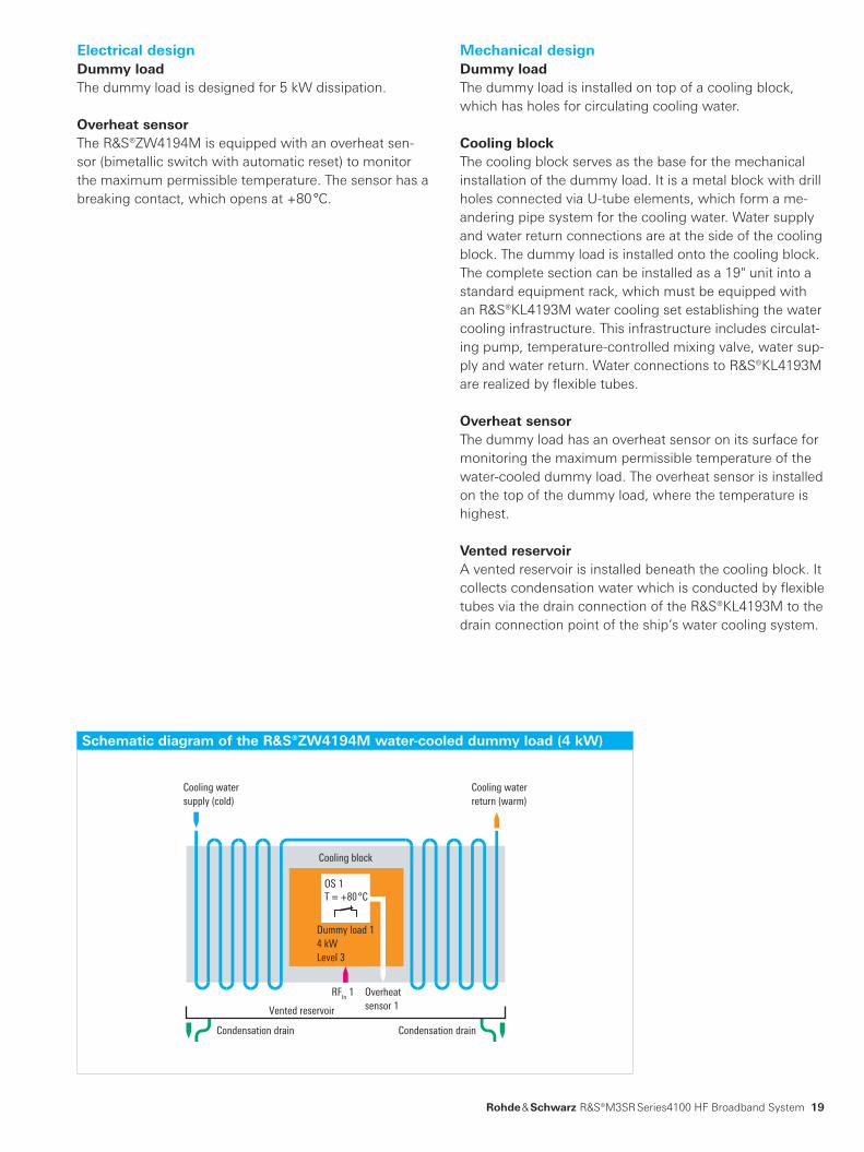
Mechanical designDummy loadThe dummy load is installed on top of a cooling block, which has holes for circulating cooling water.
Cooling blockThe cooling block serves as the base for the mechanical installation of the dummy load. It is a metal block with drill holes connected via U-tube elements, which form a me-andering pipe system for the cooling water. Water supply and water return connections are at the side of the cooling block. The dummy load is installed onto the cooling block. The complete section can be installed as a 19" unit into a standard equipment rack, which must be equipped with an R&S®KL4193M water cooling set establishing the water cooling infrastructure. This infrastructure includes circulat-ing pump, temperature-controlled mixing valve, water sup-ply and water return. Water connections to R&S®KL4193M are realized by flexible tubes.
Overheat sensorThe dummy load has an overheat sensor on its surface for monitoring the maximum permissible temperature of the water-cooled dummy load. The overheat sensor is installed on the top of the dummy load, where the temperature is highest.
Vented reservoirA vented reservoir is installed beneath the cooling block. It collects condensation water which is conducted by flexible tubes via the drain connection of the R&S®KL4193M to the drain connection point of the ship’s water cooling system.
Electrical designDummy loadThe dummy load is designed for 5 kW dissipation.
Overheat sensorThe R&S®ZW4194M is equipped with an overheat sen-sor (bimetallic switch with automatic reset) to monitor the maximum permissible temperature. The sensor has a breaking contact, which opens at +80 °C.
Schematic diagram of the R&S®ZW4194M water-cooled dummy load (4 kW)
Series4100_HFBB_bro_en_5214-1243-12_v0200.indd 19 15.07.2013 15:37:01

R&S®GU4190A remote
alarm unit.
20
R&S®GU4190 overheat watch panel, R&S®GU4190A remote alarm unit
the disabled PMUs has a four-level hierarchy (level 1 + 2, level 3,level4andlevel5),whichisnecessaryforsystemswith more than four four-line broadband blocks (two OWP required). In applications with two four-line blocks per OWP, the required hierarchy levels are limited (level 1 + 2 and level 3).
The overheat watch panel is additionally equipped with an input for a water flow sensor (WFS) which is installed in the R&S®KL4193M water cooling set. It is located in the water supply of the water-cooled dummy loads. The sensor indicates whether the required volume of water is circulating throughout the dummy loads. If this is not the case, the overheat watch panel indicates this state to a connected remote alarm unit (RAU). The RAU signals this state with both an acoustic and visual alarm. The acoustic alarm can be reset on the RAU by pressing a reset but-ton. The RAU shows the visual alarm and that the acoustic alarm has been reset. An additional interface at the over-heat watch panel with a relay contact is provided to indi-cate alarms triggered by the water flow sensor on other equipment such as a remote control system.
Key facts ❙ Monitors one water flow sensor (WFS) ❙ Controls one remote alarm unit ❙ Remote control (RC) interface signaling WFS status information
❙ Monitors up to eight overheat sensors at water-cooled dummy loads:
■ Four at level 1 + 2 ■ Two at level 3 ■ One at level 4 ■ One at level 5
❙ Controls up to four R&S®GV4190 power management units (PMU)
❙ Provides an interface for interconnecting several R&S®GU4190 overheat watch panels (required for large systems with more than four four-line blocks)
❙ Power supply, 100 V to 240 V AC ❙ Secondary power supply, 19 V to 32 V DC ❙ 19" unit, 1 HU
R&S®GU4190
over heat watch panel.
Brief descriptionThe R&S®GU4190 overheat watch panel (OWP) moni-tors the water cooling components and protects them from overloading. The OWP is controlled by overheat sensors at the water-cooled dummy loads and controls the R&S®GV4190D power management units (PMUs), which are the main components of a four-line broadband block. The task is to ensure that dummy loads are always pro-tected against damage caused by thermal overload while at the same time preventing transmissions from being aborted unnecessarily.
If one of the connected dummy loads is overloaded, the overheat watch panel indicates this state to the PMU. This interrupts all transmission from the connected radios. The front panel of the overheat watch panel is equipped with LEDs that indicate which overheat sensor has trig-gered and which PMU has been disabled. The signaling of
Series4100_HFBB_bro_en_5214-1243-12_v0200.indd 20 15.07.2013 15:37:03

Rohde & Schwarz R&S®M3SR Series4100 HF Broadband System 21
Electrical designBackplaneThe backplane is a circuit board installed in the rear p anel. ItincludesallconnectorsforinterfacingwiththeHF broad-band system and also the logic of the unit.
AC power supplyThe AC power supply is the main supply for the unit.
Connection boardThe connection board is placed between the backplane and the front panel. This board also has a DIP switch register that has to be set in accordance with the respec-tive system layout.
Rear panel elementsAll connectors for the HF broadband system and for the power supply are on the rear panel. The power switch for the AC supply is part of the power supply. All connectors can be secured against falling off.
Front panel elementsThe front panel has a circuit board with the following LED status indicators: ❙ Power 12 V ❙ AC supply ❙ Battery ❙ WFS OK ❙ WFS error ❙ Overheat level 1 + 2 (four LEDs) ❙ Overheat level 3 (two LED) ❙ Overheat level 4 (one LED) ❙ Overheat level 5 (one LED) ❙ Disabled PMUs 1 to 4 (four LEDs)
ApplicationThe R&S®GU4190 overheat watch panel can be used for a variety of applications. For installation in a system as de-scribed here, a single OWP is used to control up to two broadband blocks (eight lines) and one water flow sensor. As many as four OWPs can be combined to accommodate configurations with more than eight lines.
AC powersupply
Overheat sensorslevel 1 + 2
DisablePMUs
Water flowsensor
¸GU4190Aremote alarm unit
Remote control
Overheat sensorslevel 3
Overheat sensorlevel 4
Overheat sensorlevel 5
2nd ¸GU4190overheat watch panel
Backplane
AC mains
Battery
Front panel
Power LEDs Sensor LEDsWFS LEDs PMU LEDs
Connectionboard
Stat
us
5 V
DC
DC/DCconverter
12 V/20 Vconverter
12 V/5 Vconverter
Stat
us
12 V
DC
20 V
DC
12 V
DC
20 V
DC
5 V
DC
12 V DC
Logic
¸GU4190 overheat watch panel (block diagram)
Rear view of the
R&S®GU4190
overheat watch panel.
Series4100_HFBB_bro_en_5214-1243-12_v0200.indd 21 15.07.2013 15:37:05

22
Product overviewHF broadband system
Designation TypeBase units
Power Management Unit, incl. HF receiver/exciter functionality, base unit, DC, without local control panel and radio software R&S®MR4100G-B
HF Receiver/Exciter, base unit: DC, without local control panel and radio software R&S®MR4100G
Radio software
Software CD without export restriction R&S®DS4100A
Software CD with export restriction R&S®DS4100D
Hardware options
Local Control Panel (without audio, incl. software and LAN) R&S®GB4000C
Digitally Tuned RF Selection, 40 dB, functional for transmitting and receiving section (mandatory option) R&S®FK4140
NMEA (DSC) Interface, for connection to an external DSC controller (GMDSS) R&S®GS4102
Power amplifier
1000 W HF Power Amplifier, prepared for R&S®ZW2910 option R&S®VK4190
Termination Resistor, 200 W, for receive path incl. connecting cable (mandatory option) R&S®ZW2910
Power supply units
Powersupply,115VAC,1phase+Nor230VAC,1or3phases+N/208VAC,3-phaseΔ R&S®IN4190
Power Supply, 440 V AC, 3 phases (used together with R&S®BV4190 transformer) R&S®IN4190
Transformer,440VAC,3-phaseΔ R&S®BV4190
System components
Power Combiner, 2 kW R&S®FK4192
Power Combiner, 4 kW R&S®FK4194
Antenna Triplexer R&S®FK2950
Antenna Diplexer R&S®FK2960
Software options and auxiliary equipment are described in the R&S®M3SR Series4100 product brochure (see PD 5213.9557.12andwww.rohde-schwarz.com).
The radio systems described are hardware- and software-configurable. The system delivered has the configuration as confirmed in the order.
Your local Rohde & Schwarz expert will help you determine the optimum solution for your requirements.To find your nearest Rohde & Schwarz representative, visitwww.sales.rohde-schwarz.com
Water cooling equipment for HF broadband systems
Designation TypeHeat Exchanger R&S®KL4192M
Water Cooling Set R&S®KL4193M
Water-Cooled Dummy Load (1+2+1 kW) R&S®ZW4193M
Water-Cooled Dummy Load (4 kW) R&S®ZW4194M
Overheat Watch Panel R&S®GU4190
Remote Alarm Unit R&S®GU4190A
Series4100_HFBB_bro_en_5214-1243-12_v0200.indd 22 15.07.2013 15:37:05

Rohde & Schwarz R&S®M3SR Series4100 HF Broadband System 23
Canada
USA
Mexico
Brazil
Colombia
ArgentinaUruguay
ChileSouth Africa
United ArabEmirates
Saudi Arabia India
Pakistan
KazakhstanMongolia
China
Egypt
IsraelAlgeria
Senegal
Nigeria
Kenya
Jordan
Oman
Tunisia
Japan
SouthKorea
Malaysia
Indonesia
Australia
Singapore
New Zealand
Philippines
Taiwan
ThailandVietnam
Germany
Dallas
Portland
New Delhi
Hyderabad
Bangalore
Shanghai
Shenzhen
Beijing
Hong Kong
Los AngelesColumbia/Maryland
Munich
Cologne
United Kingdom
Ukraine
Turkey
Switzerland
Sweden
Spain
Russian Federation
Romania
Bulgaria
Portugal
Poland
Norway
Netherlands
Italy
Hungary
Greece
Malta
France
Finland
Denmark
Czech RepublicBelgium
Austria
Cyprus
Azerbaijan
Lithuania
Latvia
Estonia
Slovenia
Serbia
Sales level
Sales locations
Service level
Backup service
Area support center
Local service center
Calibration and maintenance with standardized automatic calibration systems
Calibration and maintenance
Maintenance
From pre-sale to service. At your doorstep.
TheRohde&Schwarznetworkinover70countriesensuresoptimum on-site support by highly qualified experts. User risks are reduced to a minimum at all stages of the project: ❙ Solutionfinding/purchase ❙ Technical startup/application development/integration ❙ Training ❙ Operation/calibration/repair
Series4100_HFBB_bro_en_5214-1243-12_v0200.indd 23 15.07.2013 15:37:06

About Rohde & SchwarzRohde & Schwarz is an independent group of companies specializing in electronics. It is a leading supplier of solu-tions in the fields of test and measurement, broadcasting, radiomonitoring and radiolocation, as well as secure communications. Established more than 75 years ago, Rohde & Schwarz has a global presence and a dedicated service network in over 70 countries. Company headquar-ters are in Munich, Germany.
Certified Quality System
ISO 9001
R&S® is a registered trademark of Rohde & Schwarz GmbH & Co. KG
Trade names are trademarks of the owners | Printed in Germany (ch)
PD 5214.1243.12 | Version 02.00 | July 2013 | R&S®M3SR Series4100
Data without tolerance limits is not binding | Subject to change
©2012-2013Rohde&SchwarzGmbH&Co.KG|81671München,Germany
Regional contact ❙ Europe, Africa, Middle East | +49 89 4129 12345 [email protected]
❙ North America | 1 888 TEST RSA (1 888 837 87 72) [email protected]
❙ Latin America | +1 410 910 79 88 [email protected]
❙ Asia/Pacific | +65 65 13 04 88 [email protected]
❙ China | +86 800 810 8228/+86 400 650 5896 [email protected]
Rohde & Schwarz GmbH & Co. KGwww.rohde-schwarz.com
Environmental commitment ❙ Energy-efficient products ❙ Continuous improvement in environmental sustainability ❙ ISO 14001-certified environmental management system
Service you can rely on❙ Worldwide ❙ Local and personalized❙ Customized and flexible❙ Uncompromising quality ❙ Long-term dependability
Certified Quality System
AQAP-2110
5214124312
Series4100_HFBB_bro_en_5214-1243-12_v0200.indd 24 15.07.2013 15:37:06
Top Related