


Languages
Pages
Legal


Round Line Cylinders

Visit our Website and Configure your Custom Cylinder Today at www.compactautomation.com
Table of Contents
Features ......................................................................................................................................................... 1
How to Order ............................................................................................................................................... 2
Cylinders & Rod Types ............................................................................................................................... 3
Spring Forces ............................................................................................................................................... 4
Cylinder Options ......................................................................................................................................... 5
Cushions Options ....................................................................................................................................... 5
Force Factors ................................................................................................................................................ 6
Rod Length Maximum Loads & Other Rod Threads....................................................................... 6
Round Line (RL) Cylinders and Accessories
5/32" Bore (SM Series) ............................................................................................................................... 7
5/16" Bore (05 Series) ..........................................................................................................................8-10
1/2" Bore (08 Series) ......................................................................................................................... 11-14
9/16" Bore (09 Series) ....................................................................................................................... 15-17
5/8" Bore (10 Series) ......................................................................................................................... 18-21
3/4" Bore (12 Series) ......................................................................................................................... 22-27
7/8" Bore (14 Series) ......................................................................................................................... 28-31
1-1/16" Bore (17 Series) ................................................................................................................... 32-37
1-1/4" Bore (20 Series) ..................................................................................................................... 38-41
1-1/2" Bore (24 Series) ..................................................................................................................... 42-49
1-3/4" Bore (28 Series) ..................................................................................................................... 50-53
2" Bore (32 Series).............................................................................................................................. 54-57
2-1/2" Bore (40 Series) ..................................................................................................................... 58-59
3" Bore (48 Series).............................................................................................................................. 60-61
Position Sensor Switches .......................................................................................................................62
Switch Selection .......................................................................................................................................63
Flow Controls ............................................................................................................................................64
Alignment Couplers ................................................................................................................................65
Warranty Information .............................................................................................................................66

1Contact Us at: Tel.: 864.647.9521 | [email protected]
Compact Automation’s Round Line (RL) Series cylinders feature a precision rolled body construction providing a long life, low maintenance performance. With design flexibility, a wide range of bore sizes & mounting styles, the RL Series will meet your actuation needs.
Bore Size 5/16” up to 3”
Cylinder Type Single-Acting, Double-Acting, Reverse-Acting, or Spring Bias
Mounting Style Universal, Clevis, End Stud, Front Block, Stud, Trunnion
Tube 303 Stainless Steel
End Caps Aluminum
Rod 304 Stainless Steel
Bushing Bronze
Seal Options Nitrile standard, FKM available
Pressure, Max. 250 psig
Rod Type Rotating, non-rotating, or double end
Temperature, Max. 230˚F (400˚F with FKM)
Temperature, Min. 32˚F (-20˚F with FKM)
Round Line (RL) Cylinders
Features• 130+ Configurable models
• Interchangeable with multiple competitors
• 2-5 day delivery
• Low breakaway forces & long life
• Magnetic piston & rod wipers available
• Bumpers & adjustable cushions
• Multiple switch options available
• RoHS Compliant
Universal and Clevis Mounts Cylinders Include a Sintered Bronze Bushing
Sintered Bronze Rod Bushing
Position Sensor Magnet Available
A Roller Burnished Ground & Polished 303 Stainless Steel Rod Provides a smooth surface that protects the rod seal and yields a longer service life
Machined Aluminum End Caps (anodized end caps available)
Unique Piston Design Provides Full Force and Instantaneous Breakaway
304 Stainless Steel Tube
Piston Rod Connection is Threaded, Bonded and Orbit Formed for Extra Strength

2 Visit our Website and Configure your Custom Cylinder Today at www.compactautomation.com
Some options shown below may not be available in all configurations. Please reference the charts on
the following pages for complete details. Visit our online configurator at www.compactautomation.com
Stud, Front (S) Universal (U)Clevis (C) Block, Front (F)Stud, End (E) Trunnion (T)
Mounting Styles
Mounting Style
C Clevis
F Block, Front
E Stud, End
S Stud, Front
U Universal
T Trunnion Cylinder Type
B Rear Spring Bias
D Double-Acting
F Front Spring Bias
R Reverse-Acting
S Single-Acting
See page 4 for details.
Bore Size
05 5/16"
08 1/2"
09 9/16"
10 5/8"
12 3/4"
14 7/8"
17 1-1/16"
20 1-1/4"
24 1-1/2"
28 1-3/4"
32 2"
40 2-1/2"
48 3"
Available Options
A Anodized
B Bumpers
C Cushions
F Front Cushion
R Rear Cushion
H Heavy Spring
M Magnetic Piston
N No Threads
P Rotated Ports
S Side Ported
TG PTFE-Based Grease
V FKM Seals
W Rod Wiper
See page 4 for details.
Stroke
In inches and
fractions of an inch
(e.g. 1 or 1 1/2)
maximum
stroke length
Rod Type
D Double-Ended
H Hollow
N Non-Rotating
R Rotating
Round Line (RL) Cylinders
How to Order
Part No. Example: RLSDN - 14 - 1 - M
RL S D R 14 1 MRound Line
Series
3Contact Us at: Tel.: 864.647.9521 | [email protected]
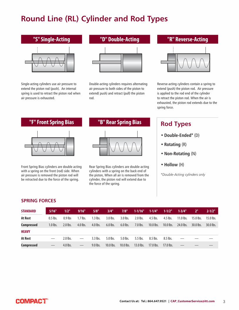
"S" Single-Acting "D" Double-Acting "R" Reverse-Acting
Single-acting cylinders use air pressure to
extend the piston rod (push). An internal
spring is used to retract the piston rod when
air pressure is exhausted.
Double-acting cylinders requires alternating
air pressure to both sides of the piston to
extend( push) and retract (pull) the piston
rod.
Reverse-acting cylinders contain a spring to
extend (push) the piston rod. Air pressure
is applied to the rod end of the cylinder
to retract the piston rod. When the air is
exhausted, the piston rod extends due to the
spring force.
"F" Front Spring Bias "B" Rear Spring Bias Rod Types
• Double-Ended* (D)
• Rotating (R)
• Non-Rotating (N)
• Hollow (H)
*Double-Acting cylinders only
Front Spring Bias cylinders are double acting
with a spring on the front (rod) side. When
air pressure is removed the piston rod will
be retracted due to the force of the spring.
Rear Spring Bias cylinders are double-acting
cylinders with a spring on the back end of
the piston, When all air is removed from the
cylinder, the piston rod will extend due to
the force of the spring.
Round Line (RL) Cylinder and Rod Types
SPRING FORCES
STANDARD 5/16" 1/2" 9/16" 5/8" 3/4" 7/8" 1-1/16" 1-1/4" 1-1/2" 1-3/4" 2" 2-1/2"
At Rest 0.5 lbs. 0.9 lbs 1.7 lbs. 1.3 lbs. 3.0 lbs. 3.0 lbs. 2.0 lbs. 4.5 lbs. 4.5 lbs. 11.0 lbs. 15.0 lbs. 15.0 lbs.
Compressed 1.0 lbs. 2.0 lbs. 4.0 lbs. 4.0 lbs. 6.0 lbs. 6.0 lbs. 7.0 lbs. 10.0 lbs. 10.0 lbs. 24.0 lbs. 30.0 lbs. 30.0 lbs.
HEAVY
At Rest — 2.0 lbs. — 3.3 lbs. 5.0 lbs. 5.0 lbs. 5.5 lbs. 8.5 lbs. 8.5 lbs. — — —
Compressed — 4.0 lbs. — 9.0 lbs. 10.0 lbs. 10.0 lbs. 13.0 lbs. 17.0 lbs. 17.0 lbs. — — —

4 Visit our Website and Configure your Custom Cylinder Today at www.compactautomation.com
LARGE ROD (LR)
Available on 1-1/4" bore round body line
only.
The following options are available
for selected Compact cylinders.
Please note that not all options are
available for all cylinders.
CUSHIONS (C, F, R) MAGNETIC PISTON (M)
Adding Cushion(s) provides adjustments to
slow the piston at the end of stroke, reduc-
ing impact and prolonging the life of the cyl-
inder. Compact's Cushions feature a captive
adjustment screw that can be adjusted to
stop the piston 1/2" from the end of stroke
or decelerate the piston's movement during
the last 1/2". More Details on Page 5.
Equipping the cylinder with an internal
magnet on the piston allows the accurate
sensing of the piston's position when it
passes underneath the sensor. GMR or reed
switches are sold separately.1
More Details on Page 62-63
1. Use of this option may add to the
overall length of the cylinder.
BUMPERS (B) WIPERS (W) FKM SEALS (V)
Reduce noise and shock to the load in
applications where the cylinder is cycled
with a light load and/or high speeds.1
Max. Temperature: 200˚F
1. Use of this option may add to the
overall length of the cylinder.
Rod Wipers are recommended for
applications where cylinders exposed to
liquid wash can dry out the pre-lubricated
rod seals. FKM Rod Wipers are supplied
when the "V" options is specified.
The FKM (V) seals are used in higher
temperature applications or for chemical
compatibility requirements.
Temperature Range: -20 up to 400˚F
HEAVY SPRING (H) ROD THREADS (N) SIDE PORTED (S)
In single-acting, reverse-acting, or spring
bias cylinders, this option provides a heavier
spring to increase the standard spring force.
Standard and heavy spring forces are listed
in Spring Forces Chart on page 3.
Various rod thread sizes are available, refer
to cylinder charts for specifications. Rods
are also available with no threads (N).
See Chart on Page 6.
Side ported rear heads are sometimes
needed when the standard cylinder has the
rear port out the back. This option changes
the design of the rear head so the rear port
is located on the side of the cylinder.1
1. Use of this option may add to the
overall length of the cylinder.
ROTATED PORTS (P2-8)
For applications where ports need to be
rotated to accommodate specific space
requirements or specific port orientation for
fittings and tube attachments.
See diagram and chart (right)
PTFE GREASE (TG) ROD EXTENSIONS
Seals lubricated with PTFE grease. If a special rod extension is required, refer to
drawing above. For extensions on single- or
double-acting cylinders, indicate desired
"W" when rod is at rest with no pressure
to either port. For reverse-acting, indicate
"W" when rod is at rest with no pressure to
either port.
Option No. Rear Port Front Port
P2 B2 A2P3 B1 A2P4 B4 A2P5 B3 A2P6 B4 A1P7 B3 A1P8 B2 A1
A1
B4B1
B2
B3
A2 Thd.Length
W
Round Line (RL) Cylinder Options

5Contact Us at: Tel.: 864.647.9521 | [email protected]
Cushions decelerate the piston/rod assembly at the end of
travel, reducing impact forces/noise while enabling faster
piston speeds. Cushions will provide superior life and
better machine function in fast cycling applications.
Our adjustment needle are held captive to prevent the
needle from blowing out.
cushion seal
cushion nose
piston
piston rod port
cushion needle
cushioned exhaust path
CYLINDERS AVAILABLE WITH CUSHIONS
Bore Size Part No. Mounting Both (C) Front (F) Rear (R) Pg.
3/4"
SDD-12- Stud • •
22SDH-12- Stud • • •
SDR-12-* Stud • • •
UDR-12- Universal • • •
7/8"
SDD-14- Stud • •
28SDH-14- Stud • •
SDR-14-* Stud • • •
UDR-14- Universal • • •
1-1/16"
SDD-17- Stud • •
32SDH-17- Stud • • •
SDR-17-* Stud • • •
UDR-17- Universal • • •
1-1/4"
SDD-20- Stud • •
38SDR-20-* Stud • • •
UDR-20- Universal • • •
1-1/2"
CDR-24- Clevis • • •
43EDR-24- End Stud • • •
SDD-24- Stud • •
SDR-24-* Stud • • •
1-3/4"
SDD-28- Stud • •
50SDR-28- Stud • • •
UDR-28- Universal • • •
2"
SDD-32- Stud • •
54SDR-32-* Stud • • •
UDR-32- Universal • • •
2-1/2"
SDD-40- Stud • •
58SDR-40-* Stud • • •
UDR-40- Universal • • •
1-1/16" and 1-1/2" bore cylinders with only one cushion include bumpers on the non-cushioned end
*SDR- models have side ported rear heads
Cushioned cylinders are not designed to decelerate machine members or take the place of shock absorbers in applications with high kinetic energy. Note also that bumpers cannot be used with cushions, but can be used opposite a cushion (as with the 1-1/16" and 1-1/2" bore cylinders).
Cushion seals are Buna. FKM Seals "-V" cushion seals are not available.
• Cushions the last 1/2" of stroke
• Long-lasting nitrile cushion seal
• Easily accessible, stainless steel needle for fine adjustment of cushion
• Available at front, rear, or both ends of cylinder
• Available with magnetic pistons
Round Line (RL) Cylinder Cushions

6 Visit our Website and Configure your Custom Cylinder Today at www.compactautomation.com
BORE SIZE ROD SIZE 1" 5" 10" 15" 20" 25" 30" 35" 40"
5/16" 1/8" 110 12 3 1.3
1/2" 9/16" 5/8"
3/16" 262 59 15 6.6 3.7
3/4" 7/8" 1/4" 478 190 47 21 12 7.5
1-1/16" 5/16" 756 451 116 52 29 19 13
1-1/4" 3/8" 1,091 786 240 106 60 38 27 20
1-1/2" 7/16" 1,490 1,184 444 197 111 71 49 36 28
1-3/4" 1/2" 1,950 1,645 757 336 189 120 84 62 47
2" 2-1/2" 5/8" 3,055 2,750 1,795 821 462 295 205 150 115
3" 3/4" 4,405 4,100 3,140 1,700 950 613 425 312 240
BORE SIZE ROD SIZE EXTEND* RETRACT*
5/16" 1/8" 0.07 in2 0.06 in2
1/2" 9/16" 5/8"
3/16"0.19 in2
0.25 in2
0.31 in2
0.16 in2
0.22 in2
0.28 in2
3/4" 7/8"
1/4"0.44 in2
0.60 in2
0.39 in2
0.55 in2
1-1/16" 5/16" 0.88 in2 0.80 in2
1-1/4" 3/8" 1.20 in2 1.09 in2
1-1/2" 7/16" 1.70 in2 1.55 in2
1-3/4" 1/2" 2.40 in2 2.20 in2
2" 2-1/2"
5/8"3.10 in2
4.90 in2
2.90 in2
4.59 in2
3" 3/4" 7.00 in2 6.56 in2
Extend = Area of Bore Retract = Area of bore minus area of rod
FORCE FACTORSThe chart shown at right can be used to calculate cylinder force. The "force factors" listed indicate the nominal area for the bore and rod sizes shown. To calculate cylinder force, multiply the appropriate extend or retract force factor by the pressure being used. Compact also recommends adding a 25% safety factor for normal load movement.
FORCE FACTOR x P (Pressure) = F (Force) F x 1.25 (25% Safety Factor) = Normal Load Movement
To calculate your own force factors: A (Area) = Radius2 x π (or Diameter2 x 0.7854) F = P x A
Round Line (RL) Cylinders
If using a double rod end cylinder, use the Retract Force Factor for both extend and retract.
Bore Rod Dia. Std Thrd N1 N2 N3 N45/16" 1/8" #5-40 - - - -1/2" 9/16" 3/16" #10-32 #10-24 M5x0.8 #8-32 -5/8" 3/4"
1/4" 1/4-28 1/4-20 M6x1.0 #10-32 -7/8" 1-1/16" 5/16" 5/16-24 5/16-18 M8x1.25 1/4-28 -1-1/4" 3/8" 3/8-24 3/8-16 M8x1.25 5/16x24 -1-1/2" 7/16" 7/16-20 7/16-14 M10x1.5 3/8-24 -1-3/4" 1/2" 1/2-20 1/2-13 M12x1.5 7/16-20 -2"
5/8" 1/2-20 1/2-13 M12x1.5 7/16-20 5/8-182-1/2" 3" 3/4" 5/8-18 5/8-11 M16x1.5 1/2-20 3/4-16
OTHER ROD THREADS
MAXIMUM LOAD BY ROD LENGTH LBS.

7Contact Us at: Tel.: 864.647.9521 | [email protected]
Round Line (RL) Cylinders - 5/32" Bore
0.750
0.063dia.
0.188dia.
0.156
#10-32 thd.
0.125
#3-56 thd.
0.063dia.
0.125
0.188dia.
#10-32 thd.
0.156
#3-56 thd.
“L”
#0-80 thd. on-T model only
RLSM-2
Bore: 5/32” Mount: Rear Thread Type: Spring Return
Bore: 5/32” Mount: Rear Thread Type: Spring Return
Materials: Stainless steel tube and rod, brass piston, Nitrile U-cup
Available Stroke Length: 1/4”
Materials: Stainless steel body, piston & rod, Nitrile U-cup,Beryllium copper spring
To order: Add stroke length to the end of the part number
Model SM-3-1 SM-3-2 SM-3-3 SM-3-4
Stroke 1/4” 1/2” 3/4” 1”
Length “L” 0.740 1.171 1.593 2.000
Single Acting
Single Acting
Did you know...
The tiny SM-2 cylinder gives 2
lbs. of force at 100 psig.
B - Bumpers
C- Cushions Both Ends
F - Front Cushion Only
H - Heavy Spring Force
Standard Options
M - Magnetic Piston for Sensing
N - No Rod Thread
P* - Rotated Ports - See pg 4.
R - Rear Cushion Only
S - Side Ports
V - Fluorocarbon Seals
W - Rod Wiper
Rod Extensions - See pg 4.
Other Rod Threads - See pg 6.
RLSM-3-

8 Visit our Website and Configure your Custom Cylinder Today at www.compactautomation.com
RLSSR-05- -
Round Line (RL) Cylinders - 5/16" Bore
For B option add 0.250
Mount: Stud Type: Rotating Rod
Options: B, V, N, S
0.375
0.340
1.125* + 0.750 foreach 1/2" of stroke
0.312
#5-40 thd. 1/4-28 thd.
0.348dia.
#10-32 thd. port
.375
0.340
0.312
1.562 + stroke0.461
0.312
#5-40 thd.
0.375
3/8-24 thd.
#10-32 thd.
2 mtg. holes 0.116 dia.-thru
0.348dia.
0.500
0.500
#10-32 thd. port0.160
SDR-05
2.187 + stroke
0.375
0.340
0.3120.461
0.312
#5-40 thd.3/8-24 thd.
#10-32 thd.0.160
2 mtg. holes0.116 dia.-thru
0.375
0.3750.187
0.437dia.
#10-32 thd. port3/8-24 thd.
0.125 dia.
0.500
0.500
UDR-05
0.187 2.000 + stroke
For B option add 0.250
For B option add 0.250
For B option add 0.250
Standard Stroke Lengths: 1/2”, 1”, 1-1/2”, 2”, 3”, 4”
Spring Compressed: 1 lbs. Spring At Rest: 0.5 lbs.
Maximum Stroke: 29”
Mount: Universal Type: Rotating Rod
Options: B, V, N, P6
Standard Stroke Lengths: 1/2”, 1”, 1-1/2”, 2”, 3”, 4”
Maximum Stroke: 43”
Mount: Stud Type: Rotating Rod
Options: B, V, N, S, P6, P7, P8
Standard Stroke Lengths: 1/2”, 1”, 1-1/2”, 2”, 3”, 4”
Maximum Stroke: 43”
Mount: Universal Type: Rotating Rod
Options: B, V, N, P2, P3, P4, P5, P6, P7, P8
Single Acting
Single Acting
Double Acting
Double Acting
For S option add 0.220
1.750 + 0.750 foreach 1/2" of stroke
0.375
0.3400.312
#5-40 thd.1/4-28 thd.
0.3750.187
0.437dia.
0.125 dia.3/8-24 thd.#10-32 thd. port
USR-05
0.1871.563 + 0.750 for
each 1/2" of stroke
For S option add 0.220
Nut included, but not shown on drawing
Nuts included, but not shown on drawing
Nut included, but not shown on drawing
Nuts included, but not shown on drawing
RLUSR-05- -
RLSDR-05- -
RLUDR-05- -
Standard Stroke Lengths: 1/2”, 1”, 1-1/2”, 2”, 3”, 4”
Spring Compressed: 1 lbs. Spring At Rest: 0.5 lbs.
Maximum Stroke: 29”
B - Bumpers
C- Cushions Both Ends
F - Front Cushion Only
H - Heavy Spring Force
Standard Options
M - Magnetic Piston for Sensing
N - No Rod Thread
P* - Rotated Ports - See pg 4.
R - Rear Cushion Only
S - Side Ports
V - Fluorocarbon Seals
W - Rod Wiper
Rod Extensions - See pg 4.
Other Rod Threads - See pg 6.

9Contact Us at: Tel.: 864.647.9521 | [email protected]
Round Line (RL) Cylinders - 5/16" Bore
Reverse Acting
Reverse Acting
For B option add 0.250
For B option add 0.250
Standard Stroke Lengths: 1/2”, 1”, 1-1/2”, 2”, 3”, 4”
Spring Compressed: 1 lbs. Spring At Rest: 0.5 lbs.
Maximum Stroke: 17”
Mount: Stud Type: Rotating Rod
Options: B, V, N
Standard Stroke Lengths: 1/2”, 1”, 1-1/2”, 2”, 3”, 4”
Spring Compressed: 1 lbs. Spring At Rest: 0.5 lbs.
Maximum Stroke: 17”
Mount: Universal Type: Rotating Rod
Options: B, V, N, P2, P3, P4, P5, P6, P7, P8
0.340
0.375 + stroke
#5-40 thd.3/8-24 thd.
#10-32 thd.
0.312
0.4610.312
0.375
2 mtg. holes0.116 dia.-thru0.160
2.093 + 0.750for each 0.500 of stroke
0.375
0.1870.500
0.437dia. 0.500
3/8-24 thd.0.125
dia.
1.906 + 0.750for each 0.500 of stroke
0.187
URR-05
0.340
0.375+ stroke
#5-40 thd.
0.312
0.461
3/8-24 thd.
#10-32 thd.
0.1600.375
0.312
1.468 + 0.750for each 0.500 of stroke
0.348dia.
#10-32 thd.
0.500
0.500
2 mtg. holes 0.116 dia.-thru
SRR-05
Nuts included, but not shown on drawing
Nuts included, but not shown on drawing
RLSRR-05- -
RLURR-05- -
B - Bumpers
C- Cushions Both Ends
F - Front Cushion Only
H - Heavy Spring Force
Standard Options
M - Magnetic Piston for Sensing
N - No Rod Thread
P* - Rotated Ports - See pg 4.
R - Rear Cushion Only
S - Side Ports
V - Fluorocarbon Seals
W - Rod Wiper
Rod Extensions - See pg 4.
Other Rod Threads - See pg 6.

10 Visit our Website and Configure your Custom Cylinder Today at www.compactautomation.com
Round Line (RL) Cylinders - 5/16" Bore Accesories
Stud Nut
Part Across Nut Nut
Number Flats Thickness (Thread)
RLN04-28A 7/16” 5/32” 1/4-28
RLN04-28B 3/8” 1/8” 1/4-28
RLN06-24A 9/16” 7/32” 3/8-24
RLN06-24B 1/2” 3/32” 3/8-24
Rod Nut
Part Across Nut Nut
Number Flats Thickness (Thread)
RLN02-40 1/4” 3/32” #5-40
Rod Clevis
Material: Steel, electroless nickel plate
0.875
1.187
.140
0.156 dia.(2) places
0.125 dia.(2) places
0.187 0.500
0.156
0.437
0.187
0.578
0.312
Clevis Bracket
Material: Steel, bright zinc plated
Foot Bracket
Material: Steel, bright zinc plated
FB-0592
0.375
0.250
0.156 dia. mounting holes0.750
0.375
0.375 dia. 0.250 rad.
0.0620.437
1
Foot Bracket
Material: Steel, bright zinc plated
0.625 dia.
1.125
0.406 dia.
Locknut
#5-40Thread 0.312 Body Flats
Bronze Bearing
0.1900 dia.
0.312
Body
Rod End
Material: Steel, bright zinc plated body
Max. Static Radial Load
(rod end only): 1,624 lbs.
Fits Rod Thread Size: #5-40
RLCB-0595
RLRC-0581
RLFB-0591 RLFB-0592
RLRE-0585
MOUNTING NUTS

11Contact Us at: Tel.: 864.647.9521 | [email protected]
RLSSN-08- -
RLFSR-08- -
Round Line (RL) Cylinders - 1/2" Bore
0.750
0.375
0.750sq.
(2) mtg. holes#8-32 thd. x 0.312 deep
0.437dia.
0.625
0.062
0.562
#10-32 thd.
0.2500.812
0.437
(2) mtg. holes#8-32 thd. x 0.187 deep
0.437
1.875 + 0.937 foreach 1/2" of stroke
0.156
0.562dia.
#10-32 thd.
0.375
Standard Stroke Lengths: 1/2”, 1”, 1-1/2”, 2”, 3”, 4”
Spring Compressed: 2 lbs. Spring At Rest: 0.9 lbs.
Maximum Stroke: 23”
Mount: Front Type: Rotating Rod
Options: M, B, W, V, N, S, H
0.625
0.562 0.312
3/8-24 thd.#10-32 thd.
0.156
1.312 + 0.937 foreach 1/2" of stroke
#10-32 thd. por
Furnished with nutsFor “B” option, add 0.500 to lengthFor “M” option, add 0.312 to lengthFor “S” option, add 0.187 to length
0.312
0.687 dia.
7/16-20 thd.0.156 dia.
0.2500.500
#10-32 thd.3/8-24 thd.0.187 hex.
#10-32 thd.
2 + 0.937 for each 1/2" of stroke
0.3120.625
0.562
USN-08
1.750 + 0.937 for each 1/2" of stroke
Standard Stroke Lengths: 1/2”, 1”, 1-1/2”, 2”, 3”, 4”
Spring Compressed: 2 lbs. Spring At Rest: 0.9 lbs.
Maximum Stroke: 23”
Mount: Stud Type: Non-Rotating Rod
Options: M, B, V, N, S, H
Standard Stroke Lengths: 1/2”, 1”, 1-1/2”, 2”, 3”, 4”
Spring Compressed: 2 lbs. Spring At Rest: 0.9 lbs.
Maximum Stroke: 23”
Mount: Stud Type: Rotating Rod
Options: M, B, W, V, N, S, H
Standard Stroke Lengths: 1/2”, 1”, 1-1/2”, 2”, 3”, 4”
Spring Compressed: 2 lbs. Spring At Rest: 0.9 lbs.
Maximum Stroke: 23”
Mount: Universal Type: Non-Rotating Rod
Options: M, B, V, N, H, P6
Single Acting
Single Acting
For B option add 0.500 For M option add 0.312 For S option add 0.187
For B option add 0.375 For M option add 0.312 For S option add 0.187
Nuts included, but not shown on drawing
Furnished without nut(s). See Chart on Page 14.
0.625
0.562 0.312
3/8-24 thd.#10-32 thd.
0.156
1.312 + 0.937 foreach 1/2" of stroke
#10-32 thd. por
Furnished with nutsFor “B” option, add 0.500 to lengthFor “M” option, add 0.312 to lengthFor “S” option, add 0.187 to length
RLSSR-08- -
Single Acting
RLUSN-08- -
Single Acting
For B option add 0.500 For M option add 0.312 For S option add 0.187 Nuts included, but not shown on drawing
For B option add 0.500 For M option add 0.312
B - Bumpers
C- Cushions Both Ends
F - Front Cushion Only
H - Heavy Spring Force
Standard Options
M - Magnetic Piston for Sensing
N - No Rod Thread
P* - Rotated Ports - See pg 4.
R - Rear Cushion Only
S - Side Ports
V - Fluorocarbon Seals
W - Rod Wiper
Rod Extensions - See pg 4.
Other Rod Threads - See pg 6.

12 Visit our Website and Configure your Custom Cylinder Today at www.compactautomation.com
Round Line (RL) Cylinders - 1/2" Bore
0.312
0.687 dia.
7/16-20 thd.0.156 dia.
0.2500.500
#10-32 thd.3/8-24 thd.0.187 hex.
#10-32 thd.
2 + 0.937 for each 1/2" of stroke
0.3120.625
0.562
USN-08
1.750 + 0.937 for each 1/2" of stroke
0.750
0.375
(2) mtg. holes#8-32 thd. x 0.312 deep
0.750sq.
0.437dia. 0.562
#10-32 thd.
0.625
0.062
0.250.437
0.6870.812
(2) mtg. holes #8-32 thd. x 0.187 deep opposite side
0.437
2.062 + stroke
0.156
0.562dia.
#10-32 thd.both ports
0.375
FDR-08
0.625
0.562
0.375
#10-32 thd.
7/16-20 thd.#10-32 thd.
2.125 + stroke
0.156
0.562dia.
#10-32 thd. port
0.375
SDR-08
0.312
0.687 dia.
0.156 dia.#10-32 thd.
0.250
0.5002.812 + stroke
7/16-20 thd. typ.#10-32 thd.
0.562
0.625 0.375
2.562 + stroke
Standard Stroke Lengths: 1/2”, 1”, 1-1/2”, 2”, 3”, 4”
Spring Compressed: 2 lbs. Spring At Rest: 0.9 lbs.
Maximum Stroke: 23”
Mount: Universal Type: Rotating Rod
Options: M, B, W, V, N, H, P6
Standard Stroke Lengths: 1/2”, 1”, 1-1/2”, 2”, 3”, 4”
Maximum Stroke: 43”
Mount: Front Type: Rotating Rod
Options: M, B, W, V, N, S, P6, P7, P8
Standard Stroke Lengths: 1/2”, 1”, 1-1/2”, 2”, 3”, 4”
Maximum Stroke: 43”
Mount: Stud Type: Rotating Rod
Options: M, B, W, V, N, S, P6, P7, P8
Standard Stroke Lengths: 1/2”, 1”, 1-1/2”, 2”, 3”, 4”
Maximum Stroke: 42”
Mount: Universal Type: Rotating Rod
Options: M, B, W, V, N, P2, P3, P4, P5, P6, P7, P8
Nut included, but not shown on drawing
Furnished without nut(s). See Chart on Page 14.
Furnished without nut(s). See Chart on Page 14.
RLUSR-08- -
Single Acting
RLFDR-08- -
Double Acting
RLSDR-08- -
Double Acting
RLUDR-08- -
Double Acting
For B option add 0.500 For M option add 0.312
For B option add 0.375 For M option add 0.312 For S option add 0.187
For B option add 0.375 For M option add 0.312 For S option add 0.187
For B option add 0.375 For M option add 0.312
B - Bumpers
C- Cushions Both Ends
F - Front Cushion Only
H - Heavy Spring Force
Standard Options
M - Magnetic Piston for Sensing
N - No Rod Thread
P* - Rotated Ports - See pg 4.
R - Rear Cushion Only
S - Side Ports
V - Fluorocarbon Seals
W - Rod Wiper
Rod Extensions - See pg 4.
Other Rod Threads - See pg 6.

13Contact Us at: Tel.: 864.647.9521 | [email protected]
Round Line (RL) Cylinders - 1/2" Bore
Standard Stroke Lengths: 1/2”, 1”, 1-1/2”, 2”, 3”, 4”
Maximum Stroke: 20”
Mount: Stud Type: Double Rod
Options: M, B, W, V, N, P6, P7, P8
0.562
#10-32 thd.both ends
0.625 + stroke
4.062 + (2 x stroke)
0.375 0.375
2.812 + stroke
7/16-20 thd. both ends#10-32 thd. both ports
0.3750.375 0.625
0.562
0.687dia.
SDD-08
0.625 + stroke
0.562
#10-32 thd.
0.375
1.937 + 0.937 foreach 1/2" of stroke
7/16-20 thd.#10-32 thd. port
0.562dia.
SRR-08
0.687dia.
0.312
0.687 dia.
0.156 dia.
#10-32 thd.
0.250
0.5002.625 + 0.937
for each 0.500 of stroke
7/16-20 thd. typ.
0.375
0.625 + stroke
0.562
#10-32 thd.
2.375 + 0.937for each 0.500 of stroke
Standard Stroke Lengths: 1/2”, 1”, 1-1/2”, 2”, 3”, 4”
Spring Compressed: 2 lbs. Spring At Rest: 0.9 lbs.
Maximum Stroke: 15”
Mount: Stud Type: Rotating Rod
Options: M, B, W, V, N, H
Standard Stroke Lengths: 1/2”, 1”, 1-1/2”, 2”, 3”, 4”
Spring Compressed: 2 lbs. Spring At Rest: 0.9 lbs.
Maximum Stroke: 15”
Mount: Universal Type: Rotating Rod
Options: M, B, W, V, N, H, P2, P3,
P4, P5, P6, P7, P8
Furnished without nut(s). See Chart on Page 14.
Nuts included, but not shown on drawing
RLSDD-08- -
Double Acting
RLSRR-08- -
Reverse Acting
RLURR-08- -
Reverse Acting
For B option add 0.500 For M option add 0.312
Nuts included, but not shown on drawingFor B option add 0.500 For M option add 0.312
For B option add 0.500 For M option add 0.312
B - Bumpers
C- Cushions Both Ends
F - Front Cushion Only
H - Heavy Spring Force
Standard Options
M - Magnetic Piston for Sensing
N - No Rod Thread
P* - Rotated Ports - See pg 4.
R - Rear Cushion Only
S - Side Ports
V - Fluorocarbon Seals
W - Rod Wiper
Rod Extensions - See pg 4.
Other Rod Threads - See pg 6.

14 Visit our Website and Configure your Custom Cylinder Today at www.compactautomation.com
Round Line (RL) Cylinders - 1/2" Bore Accessories
RC-0881
0.187 dia.-thruboth sides
0.625
0.312 dia. 0.187 dia.0.562
0.375 sq.0.187
0.187
0.937
#10-32 thd.0.125
RC-0881
C B -0 8 9 5
0.203
0.218 0.875
0.312 0.500
0.218
0.500
0.125
0.203
0.156 dia.
0.750
C B -0 8 9 5
0.7650.562
Clevis Bracket
Material: Steel, bright zinc plated
Foot Bracket
Material: Steel, bright zinc plated
0.500
0.3120.625
1
0.203
0.375 dia.
0.312 rad.
0.562
1.375
0.062
0.500
0.312
0.625
0.203
1.000
0.437 dia.
0.312 rad. 0.062
0.562
1.375
0.625 dia.
1.062
0.406 dia.
Lockwasher
Locknut
#10-320.312 Body Flats
Bronze Bearing
0.190 dia.
0.312
Body
Rod End
Material: Steel, bright zinc plated body
Foot Bracket
Material: Steel, bright zinc plated
Rod Clevis
Material: Steel, electroless nickel plate
MOUNTING NUTS
RLFB-0891
RLRC-0881
RLCB-0895
RLRE-0885
RLFB-0892
Max. Static Radial Load
(rod end only): 1,624 lbs.
Fits Rod Thread Size: #5-40
Stud Nut
Part Across Nut Nut
Number Flats Thickness (Thread)
RLN06-24A 9/16” 7/32” 3/8-24
RLN06-24B 1/2” 3/32” 3/8-24
RLN07-20 11/16” 1/4” 7/16-20
Rod Nut
Part Across Nut Nut
Number Flats Thickness (Thread)
RLN03-32 3/8" 1/8" #10-32
15Contact Us at: Tel.: 864.647.9521 | [email protected]
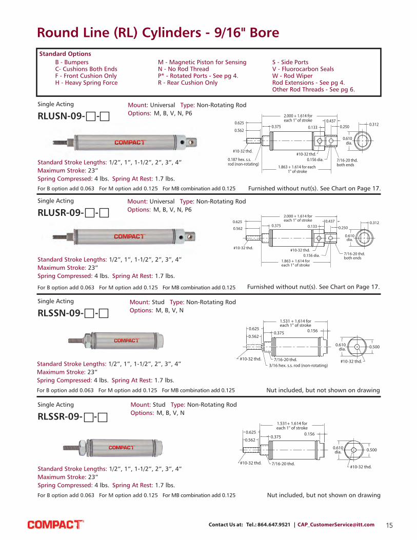
Round Line (RL) Cylinders - 9/16" Bore
0.625
0.562
#10-32 thd.
0.187 hex. s.s. rod (non-rotating)
0.375
2.000 + 1.614 foreach 1" of stroke
#10-32 thd.
0.1330.437
0.250
0.156 dia.
0.610dia.
0.312
7/16-20 thd.both ends1.863 + 1.614 for each
1" of stroke
0.625
0.5620.375
2.000 + 1.614 foreach 1" of stroke
#10-32 thd. #10-32 thd.0.156 dia.
0.1330.437
0.250
0.610dia.
0.312
7/16-20 thd.both ends
1.863 + 1.614 foreach 1" of stroke
0.625
0.5620.375
#10-32 thd.
1.531 + 1.614 foreach 1" of stroke
3/16 hex. s.s. rod (non-rotating)7/16-20 thd.
0.156
0.610dia.
#10-32 thd.
0.500
0.562
0.625
#10-32 thd. 7/16-20 thd.
0.375
1.531+ 1.614 foreach 1" of stroke
0.156
0.610dia.
#10-32 thd.
0.500
SSR-10
Nut included, but not shown on drawing
Furnished without nut(s). See Chart on Page 17.
Furnished without nut(s). See Chart on Page 17.
RLUSN-09- -
Single Acting
RLUSR-09- -
Single Acting
RLSSN-09- -
Single Acting
RLSSR-09- -
Single Acting
Standard Stroke Lengths: 1/2”, 1”, 1-1/2”, 2”, 3”, 4”
Maximum Stroke: 23”
Spring Compressed: 4 lbs. Spring At Rest: 1.7 lbs.
Mount: Universal Type: Non-Rotating Rod
Options: M, B, V, N, P6
For B option add 0.063 For M option add 0.125 For MB combination add 0.125
Standard Stroke Lengths: 1/2”, 1”, 1-1/2”, 2”, 3”, 4”
Maximum Stroke: 23”
Spring Compressed: 4 lbs. Spring At Rest: 1.7 lbs.
Mount: Universal Type: Non-Rotating Rod
Options: M, B, V, N, P6
For B option add 0.063 For M option add 0.125 For MB combination add 0.125
Standard Stroke Lengths: 1/2”, 1”, 1-1/2”, 2”, 3”, 4”
Maximum Stroke: 23”
Spring Compressed: 4 lbs. Spring At Rest: 1.7 lbs.
Mount: Stud Type: Non-Rotating Rod
Options: M, B, V, N
For B option add 0.063 For M option add 0.125 For MB combination add 0.125
Nut included, but not shown on drawing
Standard Stroke Lengths: 1/2”, 1”, 1-1/2”, 2”, 3”, 4”
Maximum Stroke: 23”
Spring Compressed: 4 lbs. Spring At Rest: 1.7 lbs.
For B option add 0.063 For M option add 0.125 For MB combination add 0.125
Mount: Stud Type: Non-Rotating Rod
Options: M, B, V, N
B - Bumpers
C- Cushions Both Ends
F - Front Cushion Only
H - Heavy Spring Force
Standard Options
M - Magnetic Piston for Sensing
N - No Rod Thread
P* - Rotated Ports - See pg 4.
R - Rear Cushion Only
S - Side Ports
V - Fluorocarbon Seals
W - Rod Wiper
Rod Extensions - See pg 4.
Other Rod Threads - See pg 6.

16 Visit our Website and Configure your Custom Cylinder Today at www.compactautomation.com
Round Line (RL) Cylinders - 9/16" Bore Accessories
0.625 + stroke
0.562
#10-32 thd.both ends
7/16-20 thd. both ends#10-32 thd. both ports
0.3750.272
4.214 + (2 x stroke)
2.964 + stroke
0.2720.375
0.562
0.625
0.610dia.
0.625 + stroke
0.562
#10-32 thd.
0.3750.272
7/16-20 thd. #10-32 thd.
2.011 + 1.614 foreach 1" of stroke
0.610dia.
SRR-10
URR-10URR-10
0.625 + stroke
9/16
0.3750.272
#10-32 thd. both ends
7/16-20 thd. both ends#10-32 thd.
2.480 + 1.614 foreach 1" of stroke
0.4370.250
0.156dia.
0.610dia.
0.312
URR-10
2.343 + 1.614 foreach 1" of stroke
For B option add 0.125 Nuts included, but not shown on drawing
Furnished without nut(s). See Chart on Page 17.
0.625
0.562
0.375
#10-32 thd.
7/16-20 thd.
#10-32 thd. both ports
2.277 + stroke
0.156
0.610dia. 0.500
SDR-10
0.272
RLSDD-09- -
Double Acting
RLSSR-09- -
Reverse Acting
RLURR-09- -
Reverse Acting
RLSDR-09- -
Double Acting
Standard Stroke Lengths: 1/2”, 1”, 1-1/2”, 2”, 3”, 4”
Maximum Stroke: 20”
Mount: Stud Type: Double Rod
Options: M, B, V, N, P6, P7, P8
For B option add 0.063 For M option add 0.125 For MB combination add 0.125
Standard Stroke Lengths: 1/2”, 1”, 1-1/2”, 2”, 3”, 4”
Maximum Stroke: 15”
Spring Compressed: 4 lbs. Spring At Rest: 1.7 lbs.
Mount: Stud Type: Rotating Rod
Options: M, B, V, N
Nuts included, but not shown on drawing
For B option add 0.063 For M option add 0.125 For MB combination add 0.125
Standard Stroke Lengths: 1/2”, 1”, 1-1/2”, 2”, 3”, 4”
Maximum Stroke: 14”
Spring Compressed: 4 lbs. Spring At Rest: 1.7 lbs.
Mount: Universal Type: Rotating Rod
Options: M, B, V, N, P2
For B option add 0.063 For MB combination add 0.125
Standard Stroke Lengths: 1/2”, 1”, 1-1/2”, 2”, 3”, 4”
Maximum Stroke: 43”
Nut included, but not shown on drawing
Mount: Stud Type: Rotating Rod
Options: M, B, V, N, P6, P7, P8
B - Bumpers
C- Cushions Both Ends
F - Front Cushion Only
H - Heavy Spring Force
Standard Options
M - Magnetic Piston for Sensing
N - No Rod Thread
P* - Rotated Ports - See pg 4.
R - Rear Cushion Only
S - Side Ports
V - Fluorocarbon Seals
W - Rod Wiper
Rod Extensions - See pg 4.
Other Rod Threads - See pg 6.

17Contact Us at: Tel.: 864.647.9521 | [email protected]
RC-0881
0.187 dia.-thruboth sides
0.625
0.312 dia. 0.187 dia.0.562
0.375 sq.0.187
0.187
0.937
#10-32 thd.0.125
RC-0881
Rod Clevis
Material: Steel, electroless nickel plate
C B -0 8 9 5
0.203
0.218 0.875
0.312 0.500
0.218
0.500
0.125
0.203
0.156 dia.
0.750
C B -0 8 9 5
0.7650.562
Clevis Bracket
Material: Steel, bright zinc plated
0.500
0.312
0.625
0.203
1.000
0.437 dia.
0.312 rad. 0.062
0.562
1.375
0.625 dia.
1.062
0.406 dia.
Lockwasher
Locknut
#10-320.312 Body Flats
Bronze Bearing
0.190 dia.
0.312
Body
Rod End
Material: Steel, bright zinc plated body
Foot Bracket
Material: Steel, bright zinc plated
0.625
0.562
0.3750.272
2.746 + stroke
0.1330.437
0.187
0.610dia.
0.312
0.156 dia.#10-32 thd.
7/16-20 thd. both ends#10-32 thd. both ports
2.559 + stroke
Double Acting
For B option add 0.125 Furnished without nut(s). See Chart below.
0.625 dia.
1.062
0.406 dia.
Lockwasher
Locknut
#10-320.312 Body Flats
Bronze Bearing
0.190 dia.
0.312
Body
0.625 dia.
1.062
0.406 dia.
Lockwasher
Locknut
#10-320.312 Body Flats
Bronze Bearing
0.190 dia.
0.312
Body
Round Line (RL) Cylinders - 9/16" Bore Accessories
RLUDR-09- -
RLCB-0895
RLRC-0881
RLRE-0885
RLFB-0892
Standard Stroke Lengths: 1/2”, 1”, 1-1/2”, 2”, 3”, 4”
Maximum Stroke: 43”
Mount: Universal Type: Rotating Rod
Options: M, B, V, N, P2, P3, P4, P5, P6, P7, P8
MOUNTING NUTS
Stud Nut
Part Across Nut Nut
Number Flats Thickness (Thread)
RLN07-20 11/16” 1/4” 7/16-20
Rod Nut
Part Across Nut Nut
Number Flats Thickness (Thread)
RLN03-32 3/8" 1/8" #10-32
Max. Static Radial Load
(rod end only): 1,624 lbs.
Fits Rod Thread Size: #10-32
18 Visit our Website and Configure your Custom Cylinder Today at www.compactautomation.com
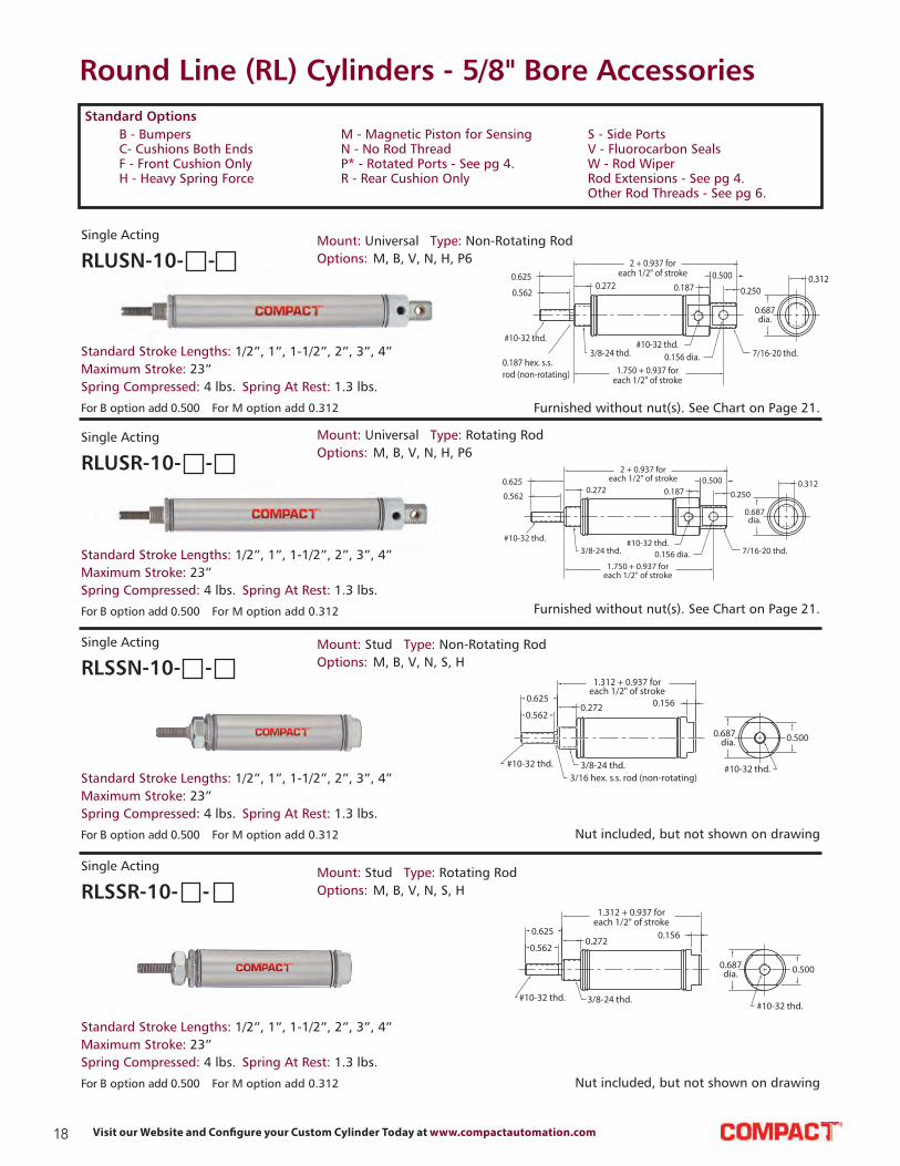
Round Line (RL) Cylinders - 5/8" Bore Accessories
0.625
0.5620.272
2 + 0.937 foreach 1/2" of stroke
#10-32 thd.3/8-24 thd.
#10-32 thd.0.156 dia.
0.1870.500
0.250
0.687dia.
0.312
USR-10
7/16-20 thd.
1.750 + 0.937 foreach 1/2" of stroke
0.625
0.5620.272
#10-32 thd.
1.312 + 0.937 foreach 1/2" of stroke
3/16 hex. s.s. rod (non-rotating)3/8-24 thd.
0.156
0.687dia.
#10-32 thd.
0.500
SSN-10
0.562
0.625
#10-32 thd. 3/8-24 thd.
0.272
1.312 + 0.937 foreach 1/2" of stroke
0.156
0.687dia.
#10-32 thd.
0.500
SSR-10
For B option add 0.500 For M option add 0.312
Nut included, but not shown on drawing
Furnished without nut(s). See Chart on Page 21.
Furnished without nut(s). See Chart on Page 21.
Standard Stroke Lengths: 1/2”, 1”, 1-1/2”, 2”, 3”, 4”
Maximum Stroke: 23”
Spring Compressed: 4 lbs. Spring At Rest: 1.3 lbs.
Mount: Universal Type: Non-Rotating Rod
Options: M, B, V, N, H, P6RLUSN-10- -
Single Acting
RLUSR-10- -
Single Acting
For B option add 0.500 For M option add 0.312
Standard Stroke Lengths: 1/2”, 1”, 1-1/2”, 2”, 3”, 4”
Maximum Stroke: 23”
Spring Compressed: 4 lbs. Spring At Rest: 1.3 lbs.
Mount: Universal Type: Rotating Rod
Options: M, B, V, N, H, P6
RLSSN-10- -
Single Acting
For B option add 0.500 For M option add 0.312
Standard Stroke Lengths: 1/2”, 1”, 1-1/2”, 2”, 3”, 4”
Maximum Stroke: 23”
Spring Compressed: 4 lbs. Spring At Rest: 1.3 lbs.
Mount: Stud Type: Non-Rotating Rod
Options: M, B, V, N, S, H
RLSSR-10- -
Single Acting
Nut included, but not shown on drawingFor B option add 0.500 For M option add 0.312
Standard Stroke Lengths: 1/2”, 1”, 1-1/2”, 2”, 3”, 4”
Maximum Stroke: 23”
Spring Compressed: 4 lbs. Spring At Rest: 1.3 lbs.
Mount: Stud Type: Rotating Rod
Options: M, B, V, N, S, H
B - Bumpers
C- Cushions Both Ends
F - Front Cushion Only
H - Heavy Spring Force
Standard Options
M - Magnetic Piston for Sensing
N - No Rod Thread
P* - Rotated Ports - See pg 4.
R - Rear Cushion Only
S - Side Ports
V - Fluorocarbon Seals
W - Rod Wiper
Rod Extensions - See pg 4.
Other Rod Threads - See pg 6.

19Contact Us at: Tel.: 864.647.9521 | [email protected]
Round Line (RL) Cylinders - 5/8" Bore
FSR-10FSR-10
0.750
0.375
0.750sq.
(2) mtg. holes#8-32 thd. x 0.312 deep
0.437dia. 0.562
0.625
0.062
#10-32 thd.
(2) mtg. holes#8-32 thd. x 0.187 deep
0.250
0.812
0.437
0.437
1.875 + .937 foreach 1/2" of stroke
0.156
0.687dia.
#10-32 thd.
0.500
FSR-10
0.750
0.375
(2) mtg. holes#8-32 thd. x 0.312 deep
0.750sq.
0.437dia.
#10-32 thd.
0.562
0.625
0.062
0.250 0.437
0.687
0.812
7/16
2.062 + stroke
0.156
0.687dia.
#10-32 thd. both ports
0.500
(2) mtg. holes #8-32 thd.0.187 deep opposite side
0.625
0.562
0.375
#10-32 thd.
7/16-20 thd.
#10-32 thd. both ports
2.125 + stroke
0.156
0.687dia. 0.500
SDR-10
0.272
0.625
0.562
0.3750.272
2.812 + stroke
0.1870.500
0.250
0.687dia.
0.312
0.156 dia.#10-32 thd.
7/16-20 thd. both ends#10-32 thd. both ports
2.562 + stroke
Furnished without nut(s). See Chart on Page 21.
Nut included, but not shown on drawing
RLFSR-10- -
Single Acting
For B option add 0.375 For M option add 0.312 For S option add 0.187
Standard Stroke Lengths: 1/2”, 1”, 1-1/2”, 2”, 3”, 4”
Maximum Stroke: 13”
Spring Compressed: 4 lbs. Spring At Rest: 1.3 lbs.
Mount: Front Type: Rotating Rod
Options: M, B, W, V, N, S, H
RLFDR-10- -
Double Acting Mount: Front Type: Rotating Rod
Options: M, B, W, V, N, S, P6, P7, P8
For B option add 0.375 For M option add 0.312 For S option add 0.187
Standard Stroke Lengths: 1/2”, 1”, 1-1/2”, 2”, 3”, 4”
Maximum Stroke: 43”
RLSDR-10- -
Double Acting
For B option add 0.375 For M option add 0.312 For S option add 0.187
Standard Stroke Lengths: 1/2”, 1”, 1-1/2”, 2”, 3”, 4”
Maximum Stroke: 43”
Mount: Stud Type: Rotating Rod
Options: M, B, W, V, N, S, P6, P7, P8
RLUDR-10- -
Double Acting Mount: Universal Type: Rotating Rod
Options: M, B, W, V, N, P2, P3, P4, P5, P6, P7, P8
For B option add 0.375 For M option add 0.312
Standard Stroke Lengths: 1/2”, 1”, 1-1/2”, 2”, 3”, 4”
Maximum Stroke: 43”
B - Bumpers
C- Cushions Both Ends
F - Front Cushion Only
H - Heavy Spring Force
Standard Options
M - Magnetic Piston for Sensing
N - No Rod Thread
P* - Rotated Ports - See pg 4.
R - Rear Cushion Only
S - Side Ports
V - Fluorocarbon Seals
W - Rod Wiper
Rod Extensions - See pg 4.
Other Rod Threads - See pg 6.

20 Visit our Website and Configure your Custom Cylinder Today at www.compactautomation.com
Round Line (RL) Cylinders - 5/8" Bore
0.625 + stroke
0.562
#10-32 thd.both ends
7/16-20 thd. both ends#10-32 thd. both ports
0.3750.272
4.062 + (2 x stroke)
2.812 + stroke
0.2720.375
0.562
0.625
0.687dia.
0.625 + stroke
0.562
#10-32 thd.
0.3750.272
7/16-20 thd. #10-32 thd.
1.937 + 0.937 foreach 1/2" of stroke
0.687dia.
SRR-10
URR-10URR-10
0.625 + stroke
9/16
0.3750.272
#10-32 thd. both ends
7/16-20 thd. both ends#10-32 thd.
2.625 + 0.937 foreach 1/2" of stroke
0.5000.250
0.156dia.
0.687dia.
0.312
URR-10
2.375 + 0.937 foreach 1/2" of stroke
Nuts included, but not shown on drawing
Nut included, but not shown on drawing
Furnished without nut(s). See Chart on Page 21.
For harsh environments,
Compact Automation's Inch
Series offers all Stainless
Steel and Composite
cylinders as standards.
RLSDD-10- -
Double Acting
For B option add 0.500 For M option add 0.312
Standard Stroke Lengths: 1/2”, 1”, 1-1/2”, 2”, 3”, 4”
Maximum Stroke: 20”
Mount: Stud Type: Double Rod
Options: M, B, W, V, N, P6, P7, P8
RLSRR-10- -
Reverse Acting Mount: Front Type: Rotating Rod
Options: M, B, W, V, N, H
For B option add 0.500 For M option add 0.312
Standard Stroke Lengths: 1/2”, 1”, 1-1/2”, 2”, 3”, 4”
Maximum Stroke: 15”
Spring Compressed: 4 lbs. Spring At Rest: 1.3 lbs.
RLURR-10- -
Reverse Acting Mount: Universal Type: Rotating Rod
Options: M, B, W, V, N, H, P2
For B option add 0.375 For M option add 0.312
Standard Stroke Lengths: 1/2”, 1”, 1-1/2”, 2”, 3”, 4”
Maximum Stroke: 14”
Spring Compressed: 4 lbs. Spring At Rest: 1.3 lbs.
B - Bumpers
C- Cushions Both Ends
F - Front Cushion Only
H - Heavy Spring Force
Standard Options
M - Magnetic Piston for Sensing
N - No Rod Thread
P* - Rotated Ports - See pg 4.
R - Rear Cushion Only
S - Side Ports
V - Fluorocarbon Seals
W - Rod Wiper
Rod Extensions - See pg 4.
Other Rod Threads - See pg 6.

21Contact Us at: Tel.: 864.647.9521 | [email protected]
Round Line (RL) Cylinders - 5/8" Bore Accessories
C B -0 8 9 5
0.203
0.218 0.875
0.312 0.500
0.218
0.500
0.125
0.203
0.156 dia.
0.750
C B -0 8 9 5
0.7650.562
RC-0881
0.187 dia.-thruboth sides
0.625
0.312 dia. 0.187 dia.0.562
0.375 sq.0.187
0.187
0.937
#10-32 thd.0.125
RC-0881
Rod Clevis
Material: Steel, electroless nickel plate
Clevis Bracket
Material: Steel, bright zinc plated
Foot Bracket
Material: Steel, bright zinc plated
0.500
0.3120.625
1
0.203
0.375 dia.
0.312 rad.
0.562
1.375
0.062
0.500
0.312
0.625
0.203
1.000
0.437 dia.
0.312 rad. 0.062
0.562
1.375
0.625 dia.
1.062
0.406 dia.
Lockwasher
Locknut
#10-320.312 Body Flats
Bronze Bearing
0.190 dia.
0.312
Body
Rod End
Material: Steel, bright zinc plated body
Foot Bracket
Material: Steel, bright zinc plated
RLCB-0895
MOUNTING NUTS
Stud Nut
Part Across Nut Nut
Number Flats Thickness (Thread)
RLN06-24A 9/16” 7/32” 3/8-24
RLN06-24B 1/2” 3/32” 3/8-24
RLN07-20 11/16” 1/4” 7/16-20
Rod Nut
Part Across Nut Nut
Number Flats Thickness (Thread)
RLN03-32 3/8" 1/8" #10-32
RLRC-0881
RLFB-0891
RLRE-0885
RLFB-0892
Max. Static Radial Load
(rod end only): 1,624 lbs.
Fits Rod Thread Size: #10-32

22 Visit our Website and Configure your Custom Cylinder Today at www.compactautomation.com
Round Line (RL) Cylinders - 3/4" Bore
1.000
0.50
(2) mtg. holes#10-32 thd. x 0.312 deep
0.625dia.
1/4-28 thd.
0.5620.625
(2) mtg. holes 0.343 dia. x 0.218 deep c’bore 0.205 dia.-thru 1/4-20 thd. x 0.250 deep from far side
0.093
0.375
2.218 + 1.687 foreach 1" of stroke
0.156
0.625
0.812dia.
1 sq.
1/8-27 NPT
FSR-12
0.625
0.625
0.5620.437
1/4-28 thd.1/4 hex. s.s. rod (non-rotating)
1/2-20 thd.
1.500 + 1.687 foreach 1" of stroke
0.156
0.625 0.812dia.
1/8-27 NPT
SSR-12
0.625
0.562
1/4-28 thd.1/2-20 thd.
0.437
1.500 + 1.687 foreach 1" of stroke
0.156
0.6250.812
dia.
1/8-27 NPT
SSR-12
Nut included, but not shown on drawing
Nut included, but not shown on drawing
RLFSR-12- -
Single Acting
RLSSN-12- -
Single Acting
RLSSR-12- -
Single Acting
RLTSR-12- -
Single Acting
Mount: Front Type: Rotating Rod
Options: M, B, W, V, N, S, H
For B option add 0.375 For M option add 0.125 For S option add 0.437
Standard Stroke Lengths: 1/2”, 1”, 1-1/2”, 2”, 3”, 4”
Maximum Stroke: 25”
Spring Compressed: 6 lbs. Spring At Rest: 3 lbs.
Mount: Stud Type: Non-Rotating Rod
Options: M, B, V, N, S, H
For B option add 0.375 For M option add 0.312 For S option add 0.437
Standard Stroke Lengths: 1/2”, 1”, 1-1/2”, 2”, 3”, 4”
Maximum Stroke: 26”
Spring Compressed: 6 lbs. Spring At Rest: 3 lbs.
Mount: Stud Type: Rotating Rod
Options: M, B, W, V, N, S, H
For B option add 0.375 For M option add 0.312 For S option add 0.437
Standard Stroke Lengths: 1/2”, 1”, 1-1/2”, 2”, 3”, 4”
Maximum Stroke: 26”
Spring Compressed: 6 lbs. Spring At Rest: 3 lbs.
Mount: Stud Type: Rotating Rod
Options: M, B, V, N, S, H
For B option add 0.375 For M option add 0.312 For S option add 0.437
Standard Stroke Lengths: 1/2”, 1”, 1-1/2”, 2”, 3”, 4”
Maximum Stroke: 25”
Spring Compressed: 6 lbs. Spring At Rest: 3 lbs.
B - Bumpers
C- Cushions Both Ends
F - Front Cushion Only
H - Heavy Spring Force
Standard Options
M - Magnetic Piston for Sensing
N - No Rod Thread
P* - Rotated Ports - See pg 4.
R - Rear Cushion Only
S - Side Ports
V - Fluorocarbon Seals
W - Rod Wiper
Rod Extensions - See pg 4.
Other Rod Threads - See pg 6.
23Contact Us at: Tel.: 864.647.9521 | [email protected]
Round Line (RL) Cylinders - 3/4" Bore
0.562
0.6250.437
1/4-28 thd.
0.250 hex. s.s. rod (non-rotating)
1/2-20 thd.
2.562 + 1.687 foreach 1" of stroke
0.3120.625
0.281 0.375
0.875dia.
0.250 dia.5/8-18 thd.
USN-12
2.281 + 1.687 foreach 1" of stroke
USR-12
0.625
0.5620.437
1/4-28 thd. 1/2-20 thd.
2.562 + 1.687 for each 1" of stroke
0.3120.625
0.281
0.250 dia. 5/8-18 thd.
0.875dia.
0.375
USR-12
2.281 + 1.687 for each 1" of stroke
FDR-12
1.000
0.500
(2) mtg. holes#10-32 thd. x 5/16 deep
0.625dia.
0.5620.625
0.093
0.375
0.875
1/4-28 thd.
(2) mtg. holes 0.343 dia. x 0.218 deep c’bore 0.205 dia.-thru 1/4-20 thd. x 0.250 deep from far side
1/8-27 NPT both ports
2.875 + stroke
0.156
0.6250.812dia. 1 sq.
FDR-12
0.625
0.6250.562
0.625dia.
0.093
0.343
0.875
2.875 + stroke
0.156
0.6250.812
dia.
1.750
1 sq.
1/4-28 thd.
0.500 dia.
1/8-27 NPT both ports
TDR-12
Furnished without nut(s). See Chart on Page 27.
Furnished without nut(s). See Chart on Page 27.
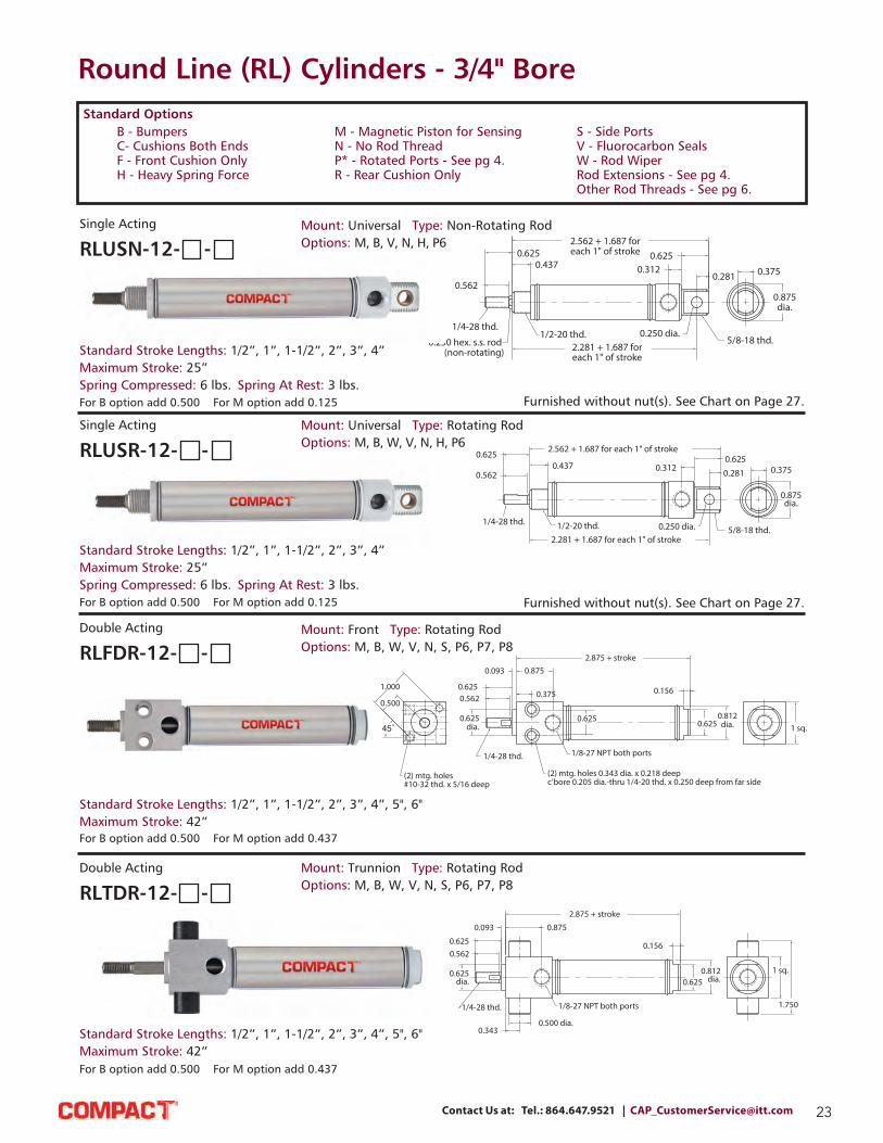
RLUSN-12- -
Single Acting Mount: Universal Type: Non-Rotating Rod
Options: M, B, V, N, H, P6
For B option add 0.500 For M option add 0.125
Standard Stroke Lengths: 1/2”, 1”, 1-1/2”, 2”, 3”, 4”
Maximum Stroke: 25”
Spring Compressed: 6 lbs. Spring At Rest: 3 lbs.
RLUSR-12- -
Single Acting
RLFDR-12- -
Double Acting
RLTDR-12- -
Double Acting
Mount: Universal Type: Rotating Rod
Options: M, B, W, V, N, H, P6
For B option add 0.500 For M option add 0.125
Standard Stroke Lengths: 1/2”, 1”, 1-1/2”, 2”, 3”, 4”
Maximum Stroke: 25”
Spring Compressed: 6 lbs. Spring At Rest: 3 lbs.
Mount: Front Type: Rotating Rod
Options: M, B, W, V, N, S, P6, P7, P8
For B option add 0.500 For M option add 0.437
Standard Stroke Lengths: 1/2”, 1”, 1-1/2”, 2”, 3”, 4”, 5", 6"
Maximum Stroke: 42”
Mount: Trunnion Type: Rotating Rod
Options: M, B, W, V, N, S, P6, P7, P8
For B option add 0.500 For M option add 0.437
Standard Stroke Lengths: 1/2”, 1”, 1-1/2”, 2”, 3”, 4”, 5", 6"
Maximum Stroke: 42”
B - Bumpers
C- Cushions Both Ends
F - Front Cushion Only
H - Heavy Spring Force
Standard Options
M - Magnetic Piston for Sensing
N - No Rod Thread
P* - Rotated Ports - See pg 4.
R - Rear Cushion Only
S - Side Ports
V - Fluorocarbon Seals
W - Rod Wiper
Rod Extensions - See pg 4.
Other Rod Threads - See pg 6.

24 Visit our Website and Configure your Custom Cylinder Today at www.compactautomation.com
Round Line (RL) Cylinders - 3/4" Bore
0.625
0.562
0.500
0.468
1/4-28 thd.
5/8-18 thd. both ends
1/8-27 NPT both ports
4.031 + stroke
0.312
0.625
0.281
0.250 dia.
0.875dia.
0.375
UDR-12
3.750 + stroke
0.625
0.562
1/4-28 thd.5/8-18 thd.
1/8-27 NPT both ports
0.5000.468
2.968 + stroke
0.156
0.625 0.875dia.
0.062 dia. - thru
1/4-28 thd. both ends
0.562
0.625 + stroke 0.5000.468
5/8-18 thd. both ends
1/8-27 NPT both ports
5.250 + (2*stroke)
4" + stroke
0.4680.500 0.625
0.562
0.875dia.
C, F, & R options use side ported rear head
Nuts included, but not shown on drawing
Nuts included, but not shown on drawing
Nuts included, but not shown on drawing
Furnished without nut(s). See Chart on Page 27.
RLUDR-12- -
Double Acting
RLSDR-12- -
Double Acting
RLSDD-12- -
Double Acting
RLSDH-12- -
Double Acting
Mount: Universal Type: Rotating Rod
Options: C, F, R, M, B, W, V, N, P2, P3, P4, P5, P6, P7, P8
For B option add 0.500
Standard Stroke Lengths: 1/2”, 1”, 1-1/2”, 2”, 3”,
4”, 5”, 6”, 8”, 10”, 12”
Maximum Stroke: 41”
Mount: Stud Type: Rotating Rod
Options: C, F, R, M, B, W, V, N, S, P6, P7, P8
For B option add 0.500 For C, F, R & S options add 0.437
Standard Stroke Lengths: 1/2”, 1”, 1-1/2”, 2”, 3”, 4”, 5”, 6”
Maximum Stroke: 42”
For harsh environments, refer to pages 64 through 69 for Stainless Steel 3/4” cylinders.
Mount: Stud Type: Double Rod
Options: C, F, M, B, W, V, N, P6, P7, P8
For B option add 0.500
Standard Stroke Lengths: 1”, 2”, 3”, 4”, 5”, 6”
Maximum Stroke: 20”
Mount: Stud Type: Hollow Rod
Options: C, F, R, M, B, W, V, N, P6, P7, P8
For B option add 0.500
Standard Stroke Lengths: 1”, 2”, 3”, 4”, 5”, 6”
Maximum Stroke: 20”
B - Bumpers
C- Cushions Both Ends
F - Front Cushion Only
H - Heavy Spring Force
Standard Options
M - Magnetic Piston for Sensing
N - No Rod Thread
P* - Rotated Ports - See pg 4.
R - Rear Cushion Only
S - Side Ports
V - Fluorocarbon Seals
W - Rod Wiper
Rod Extensions - See pg 4.
Other Rod Threads - See pg 6.

25Contact Us at: Tel.: 864.647.9521 | [email protected]
Round Line (RL) Cylinders - 3/4" Bore
0.625 + stroke0.562
1/4-28 thd.
5/8-18 thd.1/8-27 NPT
0.5000.468
2.312 + 1.687 foreach 1" of stroke
0.875dia.
SRR-12
URR-12
0.562
1/4-28 thd.
0.625 + stroke
0.500 0.468
5/8-18 thd.both ends
1/8-27 NPT 0.250 dia.
0.281
0.6252.718 + 1.687 for each 1" of stroke
0.875dia.
0.375
URR-12
2.437 + 1.687 for each 1" of stroke
0.562
1/4-28 thd. both ends
0.625 + stroke0.500
0.468
5/8-18 thd. both ends
1/8-27 NPT both ports
0.468
0.500
5.375 + 2.687for each 1" of stroke
4.125 + 1.687for each 1" of stroke 0.625
0.562
0.875dia.
0.562
0.625 + stroke
1/4-28 thd.
5/8-18 thd.1/8-27 NPT both ports
0.5000.468
3.093 + 1.687for each 1" of stroke
0.156
0.625 0.875dia.
Nut included, but not shown on drawing
Nuts included, but not shown on drawing
Furnished without nut(s). See Chart on Page 27.
RLSRR-12- -
Reverse Acting Mount: Stud Type: Rotating Rod
Options: M, B, W, V, N, H
Standard Stroke Lengths: 1/2”, 1”, 1-1/2”, 2”, 3”, 4”
Maximum Stroke: 16”
Spring Compressed: 6 lbs. Spring At Rest: 3 lbs.
For B option add 0.375 For M option add 0.125
RLURR-12- -
Reverse Acting Mount: Universal Type: Rotating Rod
Options: M, B, W, V, N, H, P2
Standard Stroke Lengths: 1/2”, 1”, 1-1/2”, 2”, 3”, 4”
Maximum Stroke: 15”
Spring Compressed: 6 lbs. Spring At Rest: 3 lbs.
For B option add 0.500 For M option add 0.125
RLSFD-12- -
Double Acting, Spring Bias Mount: Stud Type: Double Rod
Options: M, B, W, V, N, H,
P6, P7, P8
Standard Stroke Lengths: 1/2”, 1”, 1-1/2”, 2”, 3”, 4”
Maximum Stroke: 15”
Spring Compressed: 6 lbs. Spring At Rest: 3 lbs.
For B option add 0.375
Nut included, but not shown on drawing
RLSBR-12- -
Double Acting, Rear Spring Bias Mount: Stud Type: Rotating Rod
Options: M, B, W, V, N, S, H,
P6, P7, P8
Standard Stroke Lengths: 1/2”, 1”, 1-1/2”, 2”, 3”, 4”
Maximum Stroke: 15”
Spring Compressed: 6 lbs. Spring At Rest: 3 lbs.
For B option add 0.375 For S option add 0.437
B - Bumpers
C- Cushions Both Ends
F - Front Cushion Only
H - Heavy Spring Force
Standard Options
M - Magnetic Piston for Sensing
N - No Rod Thread
P* - Rotated Ports - See pg 4.
R - Rear Cushion Only
S - Side Ports
V - Fluorocarbon Seals
W - Rod Wiper
Rod Extensions - See pg 4.
Other Rod Threads - See pg 6.

26 Visit our Website and Configure your Custom Cylinder Today at www.compactautomation.com
Round Line (RL) Cylinders - 3/4" Bore
0.562
0.6250.500
0.406
1/4-28 thd.
5/8-18 thd. 1/8-27 NPT both ports
0.625
0.156
3.093 + 1.687for each 1" of stroke
0.875dia.
SFR-12
0.375
0.875dia.
0.250 dia.
0.281
0.6250.3124.156 + 1.687
for each 1" of stroke0.500
0.468
0.625 + stroke
0.562
1/4-28 thd.
5/8-18 thd. both ends1/8-27 NPT both ports
3.875 + 1.687for each 1" of stroke
0.375
0.875dia.
0.281
0.250 dia.
0.6250.3124.156 + 1.687
for each 1" of stroke
1/8-27 NPT both ports
0.468
5/8-18 thd. both ends
0.5000.625
0.562
1/4-28 thd.
3.875 + 1.687for each 1" of stroke
UFR-12
Nut included, but not shown on drawing
Furnished without nut(s). See Chart on Page 27..
Furnished without nut(s). See Chart on Page 27.
RLSFR-12- -
Double Acting, Front Spring Bias Mount: Stud Type: Rotating Rod
Options: M, B, W, V, N, S, H,
P6, P7, P8
Standard Stroke Lengths: 1/2”, 1”, 1-1/2”, 2”, 3”, 4”
Maximum Stroke: 25”
Spring Compressed: 6 lbs. Spring At Rest: 3 lbs.
For B option add 0.375 For M option add 0.437
RLUBR-12- -
Double Acting, Rear Spring Bias Mount: Universal Type: Rotating Rod
Options: M, B, W, V, N, H, P2,
P3, P4, P5, P6, P7, P8
For B option add 0.375
Standard Stroke Lengths: 1/2”, 1”, 1-1/2”, 2”, 3”, 4”
Maximum Stroke: 15”
Spring Compressed: 6 lbs. Spring At Rest: 3 lbs.
RLUFR-12- -
Double Acting, Front Spring Bias Mount: Universal Type: Rotating Rod
Options: M, B, W, V, N, H, P2,
P3, P4, P5, P6, P7, P8
For B option add 0.375
Standard Stroke Lengths: 1/2”, 1”, 1-1/2”, 2”, 3”, 4”
Maximum Stroke: 24”
Spring Compressed: 6 lbs. Spring At Rest: 3 lbs.
B - Bumpers
C- Cushions Both Ends
F - Front Cushion Only
H - Heavy Spring Force
Standard Options
M - Magnetic Piston for Sensing
N - No Rod Thread
P* - Rotated Ports - See pg 4.
R - Rear Cushion Only
S - Side Ports
V - Fluorocarbon Seals
W - Rod Wiper
Rod Extensions - See pg 4.
Other Rod Threads - See pg 6.

27Contact Us at: Tel.: 864.647.9521 | [email protected]
Round Line (RL) Cylinders - 3/4" Bore Accessories
0.797
0.375dia.
0.250 dia.
0.250 dia.-thruboth sides
0.500 sq.0.250
0.250
1/4-28 thd.
0.687
1.187
0.156
Rod Clevis
Material: Steel, electroless nickel plate
Clevis Bracket
Material: Steel, bright zinc plated
Foot Bracket
Material: Steel, bright zinc plated
0.750
0.437
0.625
1.250
0.203
0.500 dia.
0.406 rad.
0.687
0.125
1.625
0.750
0.265
1.500
0.5621
0.625 dia.
0.562 rad.
0.812
1.875
0.125
0.750 dia.
1.312
0.468 dia
Lockwasher
Locknut
1/4-280.375 Body Flats
Bronze Bearing
0.250 dia.
0.375
Body
Rod End
Material: Steel, bright zinc plated body
Foot Bracket
Material: Steel, bright zinc plated
RLCB-1795
Stud Nut
Part Across Nut Nut
Number Flats Thickness (Thread)
RLN08-20 3/4” 5/16” 1/2-20
RLN10-18 15/16” 3/8” 5/8-18
Rod Nut
Part Across Nut Nut
Number Flats Thickness (Thread)
RLN04-28A 7/16” 5/32” 1/4-28
RLN04-28B 3/8” 1/8” 1/4-28
MOUNTING NUTS
RLCB-1281
RLFB-1291 RLFB-1791
RLRE-1285
Max. Static Radial Load
(rod end only): 2,545 lbs.
Fits Rod Thread Size: #1/4-28

28 Visit our Website and Configure your Custom Cylinder Today at www.compactautomation.com
Round Line (RL) Cylinders - 7/8" Bore
SSN-14
0.625 1.843 + 1.562 foreach 1" of stroke
0.5000.562
1/4-28 thd.5/8-18 thd.
0.187 1/8-27 NPT
0.625
0.937dia.
SSN-14
SSR-14
1/4-28 thd. 5/8-18 thd.
0.500
0.625
0.562
1.843 + 1.562 for each 1" of stroke
0.187
0.937dia.
0.625
1/8-27 NPT
USN-14
0.625
0.562
0.500
1/4-28 thd.5/8-18 thd. both ends
2.750 + 1.562 foreach 1" of stroke
0.2810.625
0.281 0.375
0.937dia.
0.250 dia.1/8-27 NPT
2.469 + 1.562 foreach 1" of stroke
0.625
0.5000.562
1/4-28 thd.5/8-18 thd. both ends
2.750 + 1.562 foreach 1" of stroke
0.281
0.625
1/8-27 NPT0.250 dia.
0.281
0.937dia.
0.375
USR-14
2.469 + 1.562 foreach 1" of stroke
Bumpers are standard For M option add 0.125 For S option add 0.281 Nut included, but not shown on drawing
Nut included, but not shown on drawing
Furnished without nut(s). See Chart on Page 31.
Furnished without nut(s). See Chart on Page 31.
RLSSN-14- -
Single Acting Mount: Stud Type: Non-Rotating Rod
Options: M, V, H, S, N
Standard Stroke Lengths: 1/2”, 1”, 1-1/2”, 2”, 3”, 4”
Maximum Stroke: 27”
Spring Compressed: 6 lbs. Spring At Rest: 3 lbs.
RLSSR-14- -
Single Acting
RLUSN-14- -
Single Acting
RLUSR-14- -
Single Acting
Mount: Stud Type: Rotating Rod
Options: M, W, V, N, S, H
Standard Stroke Lengths: 1/2”, 1”, 1-1/2”, 2”, 3”, 4”
Maximum Stroke: 27”
Spring Compressed: 6 lbs. Spring At Rest: 3 lbs.
Bumpers are standard For M option add 0.125 For S option add 0.281
Mount: Universal Type: Non-Rotating Rod
Options: M, V, N, H, P6
Standard Stroke Lengths: 1/2”, 1”, 1-1/2”, 2”, 3”, 4”
Maximum Stroke: 27”
Spring Compressed: 6 lbs. Spring At Rest: 3 lbs.
Bumpers are standard For M option add 0.125
Mount: Universal Type: Rotating Rod
Options: M, W, V, N, H, P6
Standard Stroke Lengths: 1/2”, 1”, 1-1/2”, 2”, 3”, 4”
Maximum Stroke: 27”
Spring Compressed: 6 lbs. Spring At Rest: 3 lbs.
Bumpers are standard For M option add 0.125
B - Bumpers
C- Cushions Both Ends
F - Front Cushion Only
H - Heavy Spring Force
Standard Options
M - Magnetic Piston for Sensing
N - No Rod Thread
P* - Rotated Ports - See pg 4.
R - Rear Cushion Only
S - Side Ports
V - Fluorocarbon Seals
W - Rod Wiper
Rod Extensions - See pg 4.
Other Rod Threads - See pg 6.

29Contact Us at: Tel.: 864.647.9521 | [email protected]
Round Line (RL) Cylinders - 7/8" Bore
UDR-14
0.625
0.5620.500
1/4-28 thd.
5/8-18 thd. both ends0.468
1/8-27 NPT both ports
3.843 + stroke
0.281
0.6250.281
0.250 dia.
0.937dia.
0.375
UDR-14
3.562 + stroke
SDD-14
0.625 + stroke
0.562 0.500
1/4-28 thd.both ends
5/8-18 thd. both ends
0.468
3.781 + stroke
0.5000.625
0.562
0.468
1/8-27 NPT both ports
0.937dia.
SDD-14
5.031 + (2 x stroke)
0.062 dia.-thru
1/4-28 thd.both ends
5/8-18 thd. both ends
0.562
0.625 + stroke
0.500
0.4681/8-27 NPT both ports
0.468
3.781 + stroke
5.031 + (2 x stroke)
0.625
0.5000.562
0.937dia.
Bumpers are standard For M option add 0.125
For CM, FM and RM option add 0.312
C, F, & R options use side ported rear head
Nut included, but not shown on drawing
Nuts included, but not shown on drawing
Nuts included, but not shown on drawing
Furnished without nut(s). See Chart on Page 31.
Bumpers are standard For M option add 0.125
For C, F, R and S option add 0.281 For CM, FM, RM and SM option add 0.593
RLSDR-14- -
Double Acting Mount: Stud Type: Rotating Rod
Options: C, F, R, M, W, V, N, S, P6, P7, P8
Standard Stroke Lengths: 1/2”, 1”, 1-1/2”, 2”, 3”, 4”, 5", 6"
Maximum Stroke: 42”
RLUDR-14- -
Double Acting Mount: Universal Type: Rotating Rod
Options: C, F, R, M, W, V, N, P2, P3, P4, P5, P6, P7, P8
Standard Stroke Lengths: 1/2”, 1”, 1-1/2”, 2”, 3”, 4”, 5", 6"
Maximum Stroke: 41”
Bumpers are standard For M option add 0.125
RLSDD-14- -
Double Acting Mount: Stud Type: Double Rod
Options: C, F, M, W, V, N, P6, P7, P8
Standard Stroke Lengths: 1”, 2”, 3”, 4”, 5", 6"
Maximum Stroke: 20”
Bumpers are standard For M option add 0.125
For CM, FM and RM option add 0.312
RLSDH-14- -
Double Acting Mount: Stud Type: Hollow Rod
Options: C, F, M, W, V, N, P6, P7, P8
Standard Stroke Lengths: 1”, 2”, 3”, 4”, 5", 6"
Maximum Stroke: 20”
B - Bumpers
C- Cushions Both Ends
F - Front Cushion Only
H - Heavy Spring Force
Standard Options
M - Magnetic Piston for Sensing
N - No Rod Thread
P* - Rotated Ports - See pg 4.
R - Rear Cushion Only
S - Side Ports
V - Fluorocarbon Seals
W - Rod Wiper
Rod Extensions - See pg 4.
Other Rod Threads - See pg 6.
30 Visit our Website and Configure your Custom Cylinder Today at www.compactautomation.com
Round Line (RL) Cylinders - 7/8" Bore
1/4-28 thd.
5/8-18 thd. 0.4681/8-27 NPT
0.500
0.562
0.625+ stroke
2.312 + 1.562for each 1 of stroke
0.937dia.
URR-14
0.562
0.625 +stroke
0.500
1/4-28 thd.
5/8-18 thd. both ends
0.468 1/8-27 NPT
2.906 + 1.562 foreach 1" of stroke
0.6250.281
0.250 dia.
0.375
0.937dia.
URR-14
2.625 + 1.562 foreach 1" of stroke
Furnished without nut(s). See Chart on Page 31.
Nut included, but not shown on drawing
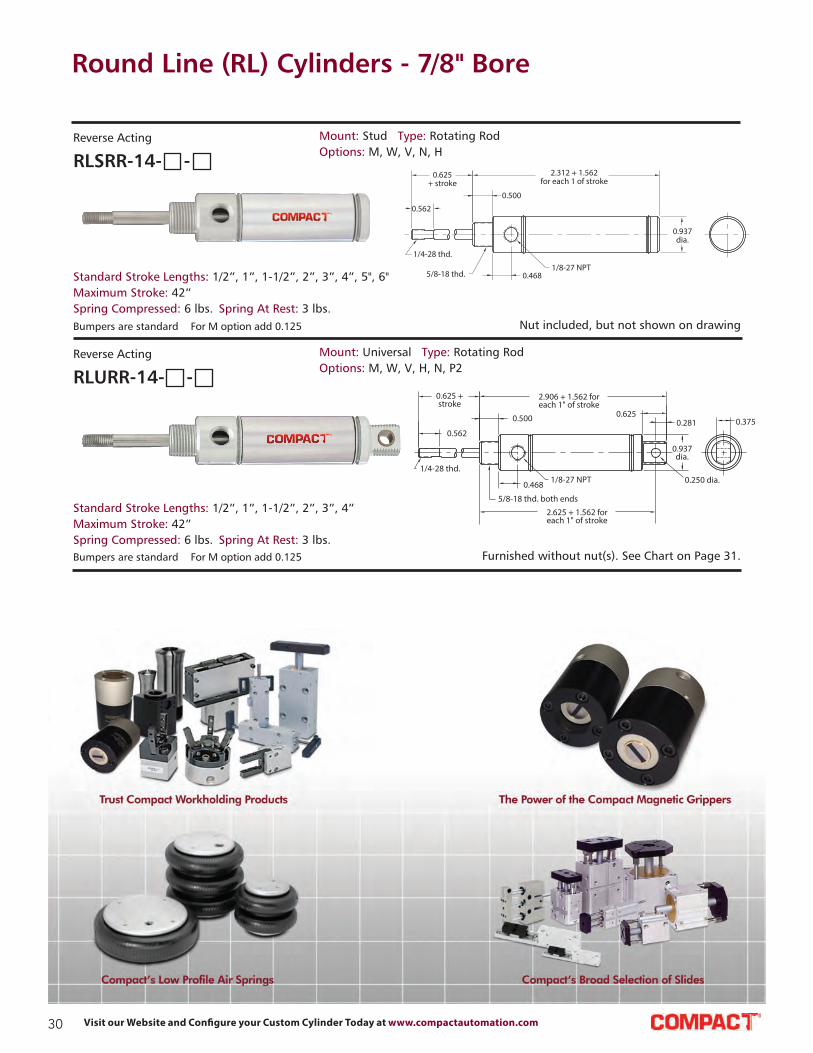
RLSRR-14- -
Reverse Acting Mount: Stud Type: Rotating Rod
Options: M, W, V, N, H
Standard Stroke Lengths: 1/2”, 1”, 1-1/2”, 2”, 3”, 4”, 5", 6"
Maximum Stroke: 42”
Spring Compressed: 6 lbs. Spring At Rest: 3 lbs.
RLURR-14- -
Reverse Acting Mount: Universal Type: Rotating Rod
Options: M, W, V, H, N, P2
Standard Stroke Lengths: 1/2”, 1”, 1-1/2”, 2”, 3”, 4”
Maximum Stroke: 42”
Spring Compressed: 6 lbs. Spring At Rest: 3 lbs.
Bumpers are standard For M option add 0.125
Bumpers are standard For M option add 0.125

31Contact Us at: Tel.: 864.647.9521 | [email protected]
Round Line (RL) Cylinders - 7/8" Bore Accessories
0.797
0.375dia.
0.250 dia.
0.250 dia.-thruboth sides
0.500 sq.0.250
0.250
1/4-28 thd.
0.687
1.187
0.156
Rod Clevis
Material: Steel, electroless nickel plate
Clevis Bracket
Material: Steel, bright zinc plated
Foot Bracket
Material: Steel, bright zinc plated
0.750
0.265
1.500
0.5621
0.625 dia.
0.562 rad.
0.812
1.875
0.125
0.750 dia.
1.312
0.468 dia
Lockwasher
Locknut
1/4-280.375 Body Flats
Bronze Bearing
0.250 dia.
0.375
Body
Rod End
Material: Steel, bright zinc plated bodyRLCB-1795
RLRC-1281
RLFB-1791
RLRE-1285
Stud Nut
Part Across Nut Nut
Number Flats Thickness (Thread)
RLN10-18 15/16” 3/8” 5/8-18
Rod Nut
Part Across Nut Nut
Number Flats Thickness (Thread)
RLN04-28A 7/16” 5/32” 1/4-28
RLN04-28B 3/8” 1/8” 1/4-28
MOUNTING NUTS
Max. Static Radial Load
(rod end only): 2,545 lbs.
Fits Rod Thread Size: #1/4-28

32 Visit our Website and Configure your Custom Cylinder Today at www.compactautomation.com
Round Line (RL) Cylinders - 1-1/16" Bore
1.250
0.625
(2) mtg. holes#10-32 thd. x 0.500 deep
5/16-24 thd.
0.750dia.
0.562
0.625
0.625
0.093 2.578 + 1.562 foreach 1" of stroke
0.187
(2) mtg. holes 0.343 dia. x 0.218deep c’bore 0.203 dia.-thru 1/4-20 thd. x 0.500 deep from far side
0.812
0.875
1.125dia.
1.250sq.
1/8-27 NPT
Lorem ipsum
0.562
0.625 0.500
1.937 + 1.562for each 1" of stroke
0.187
5/16-24 thd.
0.312 hex. s.s. rod (non-rotating)5/8-18 thd.
0.875 1.125dia.
1/8-27 NPT
SSN-17
5/16-24 thd. 5/8-18 thd.
0.562
0.625 0.500 0.187
1.937 + 1.562 for each 1" of stroke
0.8751.125dia.
1/8-27 NPT
TSR-17
5/16-24 thd.
0.500 dia.
0.750dia.
0.562
0.625
0.093 2.578 + 1.562 foreach 1" of stroke
0.6250.187
0.875
2
1.125 dia.
1/8-27 NPT
1.250sq.
TSR-17
Nut included, but not shown on drawing
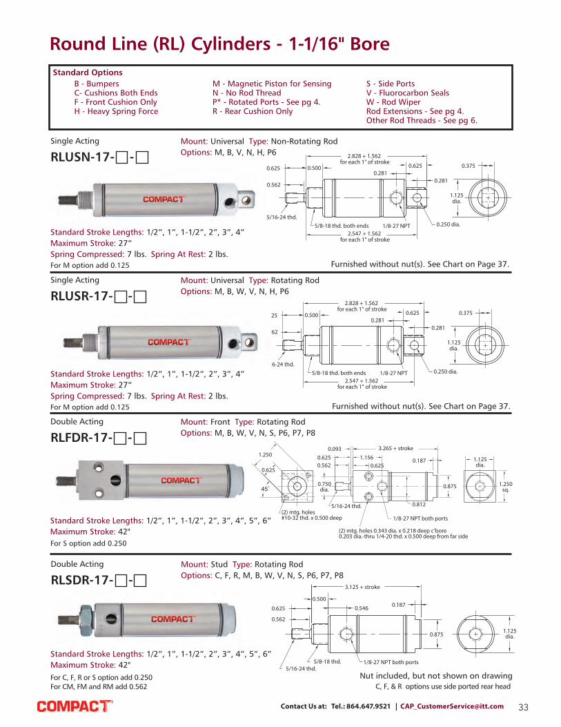
Mount: Front Type: Rotating Rod
Options: M, B, W, V, N, S, H
For M option add 0.125 For S option add 0.250
Standard Stroke Lengths: 1/2”, 1”, 1-1/2”, 2”, 3”, 4”
Maximum Stroke: 27”
Spring Compressed: 7 lbs. Spring At Rest: 2 lbs.
RLFSR-17- -
Single Acting
Mount: Stud Type: Non-Rotating Rod
Options: M, B, V, N, S, H
For M option add 0.125 For S option add 0.250
Standard Stroke Lengths: 1/2”, 1”, 1-1/2”, 2”, 3”, 4”
Maximum Stroke: 27”
Spring Compressed: 7 lbs. Spring At Rest: 2 lbs.
RLSSN-17- -
Single Acting
Mount: Stud Type: Rotating Rod
Options: M, B, W, V, N, S, H
For M option add 0.125 For S option add 0.250
Standard Stroke Lengths: 1/2”, 1”, 1-1/2”, 2”, 3”, 4”
Maximum Stroke: 27”
Spring Compressed: 7 lbs. Spring At Rest: 2 lbs.
RLSSR-17- -
Single Acting
Nut included, but not shown on drawing
Mount: Trunnion Type: Rotating Rod
Options: M, B, W, V, N, S, H
For M option add 0.125 For S option add 0.250
Standard Stroke Lengths: 1/2”, 1”, 1-1/2”, 2”, 3”, 4”
Maximum Stroke: 26”
Spring Compressed: 7 lbs. Spring At Rest: 2 lbs.
RLTSR-17- -
Single Acting
B - Bumpers
C- Cushions Both Ends
F - Front Cushion Only
H - Heavy Spring Force
Standard Options
M - Magnetic Piston for Sensing
N - No Rod Thread
P* - Rotated Ports - See pg 4.
R - Rear Cushion Only
S - Side Ports
V - Fluorocarbon Seals
W - Rod Wiper
Rod Extensions - See pg 4.
Other Rod Threads - See pg 6.
33Contact Us at: Tel.: 864.647.9521 | [email protected]
Round Line (RL) Cylinders - 1-1/16" Bore
USR-17
0.625
0.562
0.500
2.828 + 1.562 for each 1" of stroke
0.2810.625
0.281
5/16-24 thd.5/8-18 thd. both ends 1/8-27 NPT 0.250 dia.
1.125dia.
0.375
2.547 + 1.562 for each 1" of stroke
FDR-17
1.250
0.625
0.750dia.
(2) mtg. holes#10-32 thd. x 0.500 deep
5/16-24 thd.
(2) mtg. holes 0.343 dia. x 0.218 deep c’bore0.203 dia.-thru 1/4-20 thd. x 0.500 deep from far side
1/8-27 NPT both ports
0.812
0.5620.625
0.0931.156
0.625
3.265 + stroke
0.187
0.875
1.125dia.
1.250sq.
SDR-17
5/16-24 thd.5/8-18 thd. 1/8-27 NPT both ports
0.875
0.1870.546
0.562
0.625
0.500
3.125 + stroke
1.125dia.
SDR-17
For C, F, R or S option add 0.250
For CM, FM and RM add 0.562 C, F, & R options use side ported rear head
Furnished without nut(s). See Chart on Page 37.
Nut included, but not shown on drawing
USR-17
0.625
0.562
0.500
2.828 + 1.562 for each 1" of stroke
0.2810.625
0.281
5/16-24 thd.5/8-18 thd. both ends 1/8-27 NPT 0.250 dia.
1.125dia.
0.375
2.547 + 1.562 for each 1" of stroke
Furnished without nut(s). See Chart on Page 37.
Mount: Universal Type: Non-Rotating Rod
Options: M, B, V, N, H, P6
For M option add 0.125
Standard Stroke Lengths: 1/2”, 1”, 1-1/2”, 2”, 3”, 4”
Maximum Stroke: 27”
Spring Compressed: 7 lbs. Spring At Rest: 2 lbs.
RLUSN-17- -
Single Acting
Mount: Universal Type: Rotating Rod
Options: M, B, W, V, N, H, P6
For M option add 0.125
Standard Stroke Lengths: 1/2”, 1”, 1-1/2”, 2”, 3”, 4”
Maximum Stroke: 27”
Spring Compressed: 7 lbs. Spring At Rest: 2 lbs.
RLUSR-17- -
Single Acting
Mount: Front Type: Rotating Rod
Options: M, B, W, V, N, S, P6, P7, P8
For S option add 0.250
Standard Stroke Lengths: 1/2”, 1”, 1-1/2”, 2”, 3”, 4”, 5”, 6”
Maximum Stroke: 42"
RLFDR-17- -
Double Acting
Mount: Stud Type: Rotating Rod
Options: C, F, R, M, B, W, V, N, S, P6, P7, P8
Standard Stroke Lengths: 1/2”, 1”, 1-1/2”, 2”, 3”, 4”, 5”, 6”
Maximum Stroke: 42"
RLSDR-17- -
Double Acting
B - Bumpers
C- Cushions Both Ends
F - Front Cushion Only
H - Heavy Spring Force
Standard Options
M - Magnetic Piston for Sensing
N - No Rod Thread
P* - Rotated Ports - See pg 4.
R - Rear Cushion Only
S - Side Ports
V - Fluorocarbon Seals
W - Rod Wiper
Rod Extensions - See pg 4.
Other Rod Threads - See pg 6.

34 Visit our Website and Configure your Custom Cylinder Today at www.compactautomation.com
Round Line (RL) Cylinders - 1-1/16" Bore
0.093
0.625
0.562
0.750dia.
0.625
1.156
3.265 + stroke
0.187
0.875
0.500 dia.
5/16-24 thd. 1/8-27 NPT both ports
2
1.125dia.
1.250sq.
TDR-17
UDR-17
0.625
0.562
0.5000.546
4" + stroke
5/16-24 thd.
5/8-18 thd. both ends1/8-27 NPT both ports
0.2810.625
0.281
0.250 dia.
1.125dia.
0.375
3.719" + stroke
0.562
0.625 + stroke 0.500
0.546
5/16-24 thd.both ends
5/8-18 thd. both ends
1/8-27 NPT both ports
1.125dia.
0.546
0.500 0.625
0.562
4.031 + stroke
5.281 + (2 x stroke)
SDD-17
5/16-24 thd. both ends5/8-18 thd. both ends
1/8-27 NPT both ports
0.562
0.625 + stroke0.50
0.546
5.281 + (2 x stroke)
4.031 + stroke
0.5460.50
0.625
0.562
1.125dia.
hollow rod(0.160 dia.-thru)
For CM, FM and RM add 0.312
Furnished without nut(s). See Chart on Page 37.
Nuts included, but not shown on drawing
Nuts included, but not shown on drawing
Mount: Trunnion Type: Rotating Rod
Options: M, B, W, V, N, S, P6, P7, P8
For S option add 0.250
Standard Stroke Lengths: 1/2”, 1”, 1-1/2”, 2”, 3”, 4”, 5”, 6”
Maximum Stroke: 42”
RLTDR-17- -
Double Acting
Mount: Universal Type: Rotating Rod
Options: C, F, R, M, B, W, V, N, P2, P3, P4, P5, P6, P7, P8
For CM, FM and RM add 0.312
Standard Stroke Lengths: 1/2”, 1”, 1-1/2”, 2”, 3”,
4”, 5”, 6”, 8”, 10”, 12”
Maximum Stroke: 41”
RLUDR-17- -
Double Acting
Mount: Stud Type: Double Rod
Options: C, F, M, B, W, V, N, P6, P7, P8
Standard Stroke Lengths: 1”, 2”, 3”, 4”, 5”, 6”
Maximum Stroke: 20”
RLSDD-17- -
Double Acting
For CM, FM and RM add 0.312
Mount: Stud Type: Hollow Rod
Options: C, F, R, M, B, W, V, N, P6, P7, P8
Standard Stroke Lengths: 1”, 2”, 3”, 4”, 5”, 6”
Maximum Stroke: 20”
RLSDH-17- -
Double Acting
B - Bumpers
C- Cushions Both Ends
F - Front Cushion Only
H - Heavy Spring Force
Standard Options
M - Magnetic Piston for Sensing
N - No Rod Thread
P* - Rotated Ports - See pg 4.
R - Rear Cushion Only
S - Side Ports
V - Fluorocarbon Seals
W - Rod Wiper
Rod Extensions - See pg 4.
Other Rod Threads - See pg 6.
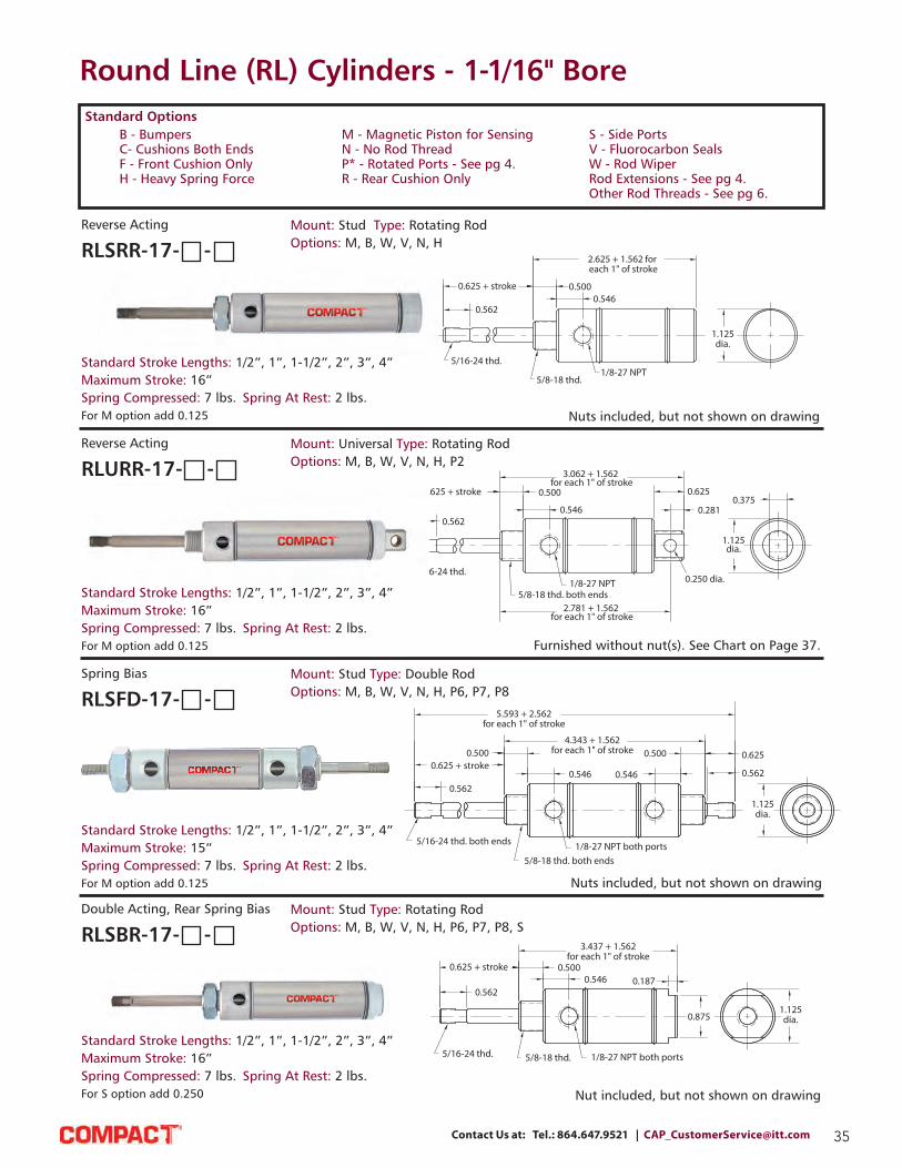
35Contact Us at: Tel.: 864.647.9521 | [email protected]
5/16-24 thd.
0.562
0.625 + stroke 0.5000.546
5/8-18 thd.1/8-27 NPT
2.625 + 1.562 for each 1" of stroke
1.125dia.
SRR-17
Round Line (RL) Cylinders - 1-1/16" Bore
URR-17
5/16-24 thd.
0.562
0.625 + stroke 0.500
0.546
5/8-18 thd. both ends1/8-27 NPT
3.062 + 1.562 for each 1" of stroke
0.625
0.281
0.250 dia.
1.125dia.
0.375
2.781 + 1.562 for each 1" of stroke
0.562
0.625 + stroke0.500
0.546
5/16-24 thd. both ends
5/8-18 thd. both ends1/8-27 NPT both ports
5.593 + 2.562for each 1" of stroke
4.343 + 1.562for each 1" of stroke
0.546
0.500 0.625
0.562
1.125dia.
SFD-17
Nuts included, but not shown on drawing
Furnished without nut(s). See Chart on Page 37.
Nuts included, but not shown on drawing
Nut included, but not shown on drawing
Mount: Stud Type: Rotating Rod
Options: M, B, W, V, N, H
For M option add 0.125
Standard Stroke Lengths: 1/2”, 1”, 1-1/2”, 2”, 3”, 4”
Maximum Stroke: 16”
Spring Compressed: 7 lbs. Spring At Rest: 2 lbs.
RLSRR-17- -
Reverse Acting
Mount: Universal Type: Rotating Rod
Options: M, B, W, V, N, H, P2
For M option add 0.125
Standard Stroke Lengths: 1/2”, 1”, 1-1/2”, 2”, 3”, 4”
Maximum Stroke: 16”
Spring Compressed: 7 lbs. Spring At Rest: 2 lbs.
RLURR-17- -
Reverse Acting
Mount: Stud Type: Double Rod
Options: M, B, W, V, N, H, P6, P7, P8
For M option add 0.125
Standard Stroke Lengths: 1/2”, 1”, 1-1/2”, 2”, 3”, 4”
Maximum Stroke: 15”
Spring Compressed: 7 lbs. Spring At Rest: 2 lbs.
RLSFD-17- -
Spring Bias
Mount: Stud Type: Rotating Rod
Options: M, B, W, V, N, H, P6, P7, P8, S
For S option add 0.250
Standard Stroke Lengths: 1/2”, 1”, 1-1/2”, 2”, 3”, 4”
Maximum Stroke: 16”
Spring Compressed: 7 lbs. Spring At Rest: 2 lbs.
RLSBR-17- -
Double Acting, Rear Spring Bias
B - Bumpers
C- Cushions Both Ends
F - Front Cushion Only
H - Heavy Spring Force
Standard Options
M - Magnetic Piston for Sensing
N - No Rod Thread
P* - Rotated Ports - See pg 4.
R - Rear Cushion Only
S - Side Ports
V - Fluorocarbon Seals
W - Rod Wiper
Rod Extensions - See pg 4.
Other Rod Threads - See pg 6.

36 Visit our Website and Configure your Custom Cylinder Today at www.compactautomation.com
Round Line (RL) Cylinders - 1-1/16" Bore
0.625
0.562
0.500
5/16-24 thd.5/8-18 thd.
1/8-27 NPT both ports
0.546
0.875 1.125dia.
0.187
3.437 + 1.562for each 1" of stroke
S F R -1 7
5/16-24 thd.
0.625 + stroke
0.562
0.5000.546
5/8-18 thd. both ends1/8-27 NPT both ports 0.250 dia.
4.312 + 1.562for each 1" of stroke
0.2810.625
1.125dia.
0.2810.375
4.031 + 1.562 for each 1" of stroke
UBR-170.625
0.562
0.500
0.546
5/16-24 thd.
5/8-18 thd. both ends1/8-27 NPT both ports
4.312 + 1.562for each 1" of stroke
0.2810.625
0.375
1.125dia.
0.250 dia.
0.281
4.031 + 1.562for each 1" of stroke
UFR-17
Nut included, but not shown on drawing
Furnished without nut(s). See Chart on Page 37.
Furnished without nut(s). See Chart on Page 37.
Mount: Stud Type: Rotating Rod
Options: M, B, W, V, N, S, H,
P6, P7, P8
For S option add 0.250
Standard Stroke Lengths: 1/2”, 1”, 1-1/2”, 2”, 3”, 4”
Maximum Stroke: 26”
Spring Compressed: 7 lbs. Spring At Rest: 2 lbs.
RLSFR-17- -
Double Acting, Spring Bias
Mount: Universal Type: Rotating Rod
Options: M, B, W, V, N, H, P2,
P3, P4, P5, P6, P7, P8
Standard Stroke Lengths: 1/2”, 1”, 1-1/2”, 2”, 3”, 4”
Maximum Stroke: 16”
Spring Compressed: 7 lbs. Spring At Rest: 2 lbs.
RLUBR-17- -
Double Acting, Rear Spring Bias
Mount: Universal Type: Rotating Rod
Options: M, B, W, V, N, H, P2,
P3, P4, P5, P6, P7, P8
Standard Stroke Lengths: 1/2”, 1”, 1-1/2”, 2”, 3”, 4”
Maximum Stroke: 26”
Spring Compressed: 7 lbs. Spring At Rest: 2 lbs.
RLUFR-17- -
Double Acting Front Spring Bias
B - Bumpers
C- Cushions Both Ends
F - Front Cushion Only
H - Heavy Spring Force
Standard Options
M - Magnetic Piston for Sensing
N - No Rod Thread
P* - Rotated Ports - See pg 4.
R - Rear Cushion Only
S - Side Ports
V - Fluorocarbon Seals
W - Rod Wiper
Rod Extensions - See pg 4.
Other Rod Threads - See pg 6.

37Contact Us at: Tel.: 864.647.9521 | [email protected]
Round Line (RL) Cylinders - 1-1/16" Bore Accessories
0.797
0.250 dia.0.375dia.
0.250 dia. - thruboth sides
5/16-24 thd. 0.187
1.187
0.250
0.2500.687
0.500 sq.
Rod Clevis
Material: Steel, electroless nickel plate
Clevis Bracket
Material: Steel, bright zinc plated
Foot Bracket
Material: Steel, bright zinc plated
0.750
0.265
1.500
0.5621
0.625 dia.
0.562 rad.
0.812
1.875
0.125
0.875 dia.
1.375
0.500 dia.
Lockwasher
Locknut
5/16-240.437 Body Flats
Bronze Bearing
0.3125 dia.
0.437
Body
Rod End
Material: Steel, bright zinc plated bodyRLCB-1795
Stud Nut
Part Across Nut Nut
Number Flats Thickness (Thread)
RLN10-18 15/16” 3/8” 5/8-18
Rod Nut
Part Across Nut Nut
Number Flats Thickness (Thread)
RLN05-24 71/2” 3/16” 5/16-24
MOUNTING NUTS
Max. Static Radial Load
(rod end only): 3,200 lbs.
Fits Rod
Thread Size: #5/16-24
RLRC-1781
RLFB-1791
RLRE-1785

38 Visit our Website and Configure your Custom Cylinder Today at www.compactautomation.com
Round Line (RL) Cylinders - 1-1/4" Bore
3/8-24 thd.
3/8 hex. s.s. rod (non-rotating)3/4-16 thd.
0.6250.250
2.406 + 1.812 for each 1" of stroke
0.875 1.312dia.
1/8-27 NPT
0.750
1.000
S S R -2 0
3/4-16 thd.
0.625
2.406 + 1.812 for each 1" of stroke
0.250
0.8751.312dia.
1/8-27 NPT
0.750
1.000
3/8-24 thd.both ends
U S N -2 0
0.750
1.000 0.6253.531 + 1.812 foreach 1" of stroke
3/8-24 thd.
3/8 hex. s.s. rod (non-rotating)
3/4-16 thd. both ends 1/8-27 NPT 0.250 dia.
0.375
0.8120.406
0.500
1.312 dia.
3.125 + 1.812 foreach 1" of stroke
U S R -2 0
0.750
1 0.6253.531 + 1.812 foreach 1" of stroke
3/8-24 thd. 3/4-16 thd. both ends
0.3750.812
0.406 0.500
1.312 dia.
1/8-27 NPT 0.250 dia.
3.125 + 1.812 foreach 1" of stroke
Note: The 1-1/4” bore is also available with a 7/16-20 threaded rod. Order -LR option.
Nut included, but not shown on drawing
Nut included, but not shown on drawing
Furnished without nut(s). See Chart on Page 41.
Furnished without nut(s). See Chart on Page 41.
Mount: Stud Type: Non-Rotating Rod
Options: M, B, V, N, S, H
For M option add 0.125 For S option add 0.312
Standard Stroke Lengths: 1/2”, 1”, 1-1/2”, 2”, 3”, 4”
Maximum Stroke: 23”
Spring Compressed: 10 lbs. Spring At Rest: 4.5 lbs.
RLSSN-20- -
Single Acting
Mount: Stud Type: Rotating Rod
Options: M, B, V, N, S, H
For M option add 0.125 For S option add 0.312
Standard Stroke Lengths: 1/2”, 1”, 1-1/2”, 2”, 3”, 4”
Maximum Stroke: 23”
Spring Compressed: 10 lbs. Spring At Rest: 4.5 lbs.
RLSSR-20- -
Single Acting
Mount: Universal Type: Non-Rotating Rod
Options: M, B, V, N, H, P6RLUSN-20- -
Single Acting
For M option add 0.125
Standard Stroke Lengths: 1/2”, 1”, 1-1/2”, 2”, 3”, 4”
Maximum Stroke: 26”
Spring Compressed: 7 lbs. Spring At Rest: 2 lbs.
For M option add 0.125
Standard Stroke Lengths: 1/2”, 1”, 1-1/2”, 2”, 3”, 4”
Maximum Stroke: 22”
Spring Compressed: 10 lbs. Spring At Rest: 4.5 lbs.
Mount: Universal Type: Rotating Rod
Options: M, B, V, N, H, P6RLUSR-20- -
Single Acting
B - Bumpers
C- Cushions Both Ends
F - Front Cushion Only
H - Heavy Spring Force
Standard Options
M - Magnetic Piston for Sensing
N - No Rod Thread
P* - Rotated Ports - See pg 4.
R - Rear Cushion Only
S - Side Ports
V - Fluorocarbon Seals
W - Rod Wiper
Rod Extensions - See pg 4.
Other Rod Threads - See pg 6.
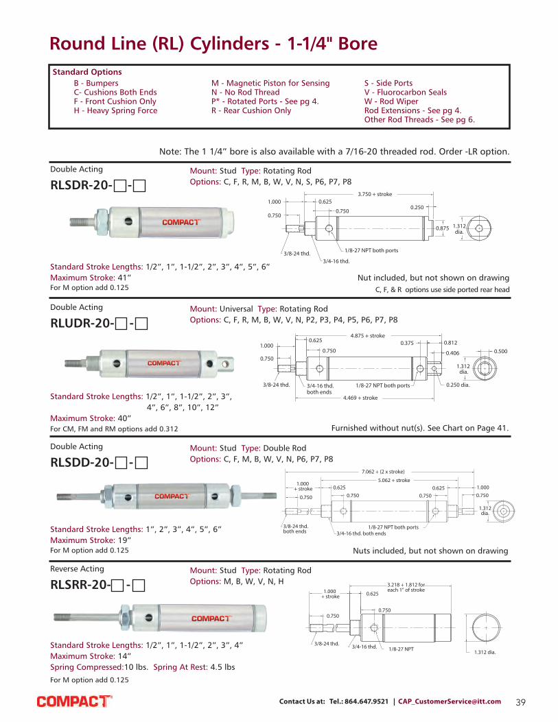
39Contact Us at: Tel.: 864.647.9521 | [email protected]
Round Line (RL) Cylinders - 1-1/4" Bore
SDR-20
0.750
1.000 0.625
0.750
3/8-24 thd.3/4-16 thd.
1/8-27 NPT both ports
3.750 + stroke
0.250
0.875 1.312dia.
UDR-20
4.875 + stroke0.375
0.750
0.6251.000
0.750
3/4-16 thd. both ends
3/8-24 thd. 1/8-27 NPT both ports 0.250 dia.
0.812
0.406 0.500
1.312 dia.
4.469 + stroke
SDD-20
0.750
1.000 + stroke 0.625
0.750
3/8-24 thd.both ends 3/4-16 thd. both ends
1/8-27 NPT both ports
7.062 + (2 x stroke)
5.062 + stroke
0.7500.625 1.000
0.750
1.312dia.
C, F, & R options use side ported rear head
Note: The 1 1/4” bore is also available with a 7/16-20 threaded rod. Order -LR option.
SRR-28
0.750
1.000 + stroke
3/8-24 thd. 3/4-16 thd. 1/8-27 NPT
0.625
0.750
1.312 dia.
3.218 + 1.812 foreach 1" of stroke
Nut included, but not shown on drawing
Furnished without nut(s). See Chart on Page 41.
Nuts included, but not shown on drawing
For M option add 0.125
Standard Stroke Lengths: 1/2”, 1”, 1-1/2”, 2”, 3”, 4”, 5”, 6”
Maximum Stroke: 41”
Mount: Stud Type: Rotating Rod
Options: C, F, R, M, B, W, V, N, S, P6, P7, P8RLSDR-20- -
Double Acting
For CM, FM and RM options add 0.312
Standard Stroke Lengths: 1/2”, 1”, 1-1/2”, 2”, 3”,
4”, 6”, 8”, 10”, 12”
Maximum Stroke: 40”
Mount: Universal Type: Rotating Rod
Options: C, F, R, M, B, W, V, N, P2, P3, P4, P5, P6, P7, P8RLUDR-20- -
Double Acting
For M option add 0.125
Standard Stroke Lengths: 1”, 2”, 3”, 4”, 5”, 6”
Maximum Stroke: 19”
Mount: Stud Type: Double Rod
Options: C, F, M, B, W, V, N, P6, P7, P8RLSDD-20- -
Double Acting
For M option add 0.125
Standard Stroke Lengths: 1/2”, 1”, 1-1/2”, 2”, 3”, 4”
Maximum Stroke: 14”
Spring Compressed: 10 lbs. Spring At Rest: 4.5 lbs
Mount: Stud Type: Rotating Rod
Options: M, B, W, V, N, HRLSRR-20- -
Reverse Acting
B - Bumpers
C- Cushions Both Ends
F - Front Cushion Only
H - Heavy Spring Force
Standard Options
M - Magnetic Piston for Sensing
N - No Rod Thread
P* - Rotated Ports - See pg 4.
R - Rear Cushion Only
S - Side Ports
V - Fluorocarbon Seals
W - Rod Wiper
Rod Extensions - See pg 4.
Other Rod Threads - See pg 6.
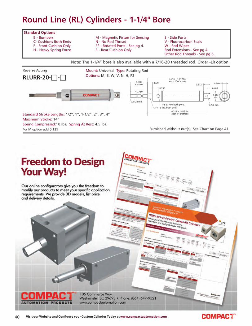
40 Visit our Website and Configure your Custom Cylinder Today at www.compactautomation.com
Round Line (RL) Cylinders - 1-1/4" Bore
URR-20
3/8-24 thd.
0.750
1.000 + stroke 0.625
0.750
4.716 + 1.812 foreach 1" of stroke
0.812
0.406
0.250 dia.3/4-16 thd. both ends
1/8-27 NPT both ports
0.500
1.312 dia.
4.311 + 1.812 foreach 1" of stroke
Note: The 1-1/4” bore is also available with a 7/16-20 threaded rod. Order -LR option.
Furnished without nut(s). See Chart on Page 41.For M option add 0.125
Standard Stroke Lengths: 1/2”, 1”, 1-1/2”, 2”, 3”, 4”
Maximum Stroke: 14”
Spring Compressed: 10 lbs. Spring At Rest: 4.5 lbs.
Mount: Universal Type: Rotating Rod
Options: M, B, W, V, N, H, P2RLURR-20- -
Reverse Acting
B - Bumpers
C- Cushions Both Ends
F - Front Cushion Only
H - Heavy Spring Force
Standard Options
M - Magnetic Piston for Sensing
N - No Rod Thread
P* - Rotated Ports - See pg 4.
R - Rear Cushion Only
S - Side Ports
V - Fluorocarbon Seals
W - Rod Wiper
Rod Extensions - See pg 4.
Other Rod Threads - See pg 6.

41Contact Us at: Tel.: 864.647.9521 | [email protected]
Round Line (RL) Cylinders - 1-1/4" Bore
C B -2 0 9 5
0.375 1.375 0.375
0.265
0.500
0.812
0.750
0.187
0.312
0.250 dia.
1.125
C B -2 0 9 5
1.1560.875
RC-2081
1.093
0.500 dia. 0.375 dia.
1.687
3/8-24 thd.0.218
0.9370.375
0.750 sq. 0.375 dia.-thruboth sides
RC-2081
0.375
Rod Clevis
Material: Steel, electroless nickel plate
Clevis Bracket
Material: Steel, bright zinc plated
Foot Bracket
Material: Steel, bright zinc plated
0.937
0.750
1.500
0.265
1.875
0.750 dia.
0.750 rad.0.156
2.500
1
1.000 dia.
1.625
0.687 dia.
Lockwasher
Locknut
3/8-240.562 Body Flats
Bronze Bearing
0.3750 dia.
Body
0.500
Rod End
Material: Steel, bright zinc plated bodyRLCB-2095
Stud Nut
Part Across Nut Nut
Number Flats Thickness (Thread)
RLN12-16 1 3/32” 27/64” 3/4-16
Rod Nut
Part Across Nut Nut
Number Flats Thickness (Thread)
RLN06-24A 9/16” 7/32” 3/8-24
RLN06-24B 1/2” 3/32” 3/8-24
MOUNTING NUTS
Max. Static Radial Load
(rod end only): 3,200 lbs.
Fits Rod
Thread Size: #5/16-24
RLRC-2081
RLFB-2491
RLRE-2085

42 Visit our Website and Configure your Custom Cylinder Today at www.compactautomation.com
0.750
1.000 0.625
7/16-20 thd.7/16 hex. s.s. rod (non-rotating)
3/4-16 thd.
3.250 + 1.687 foreach 1" of stroke
0.3120.875
0.375
1/8-27 NPT 0.375 dia.
1.000 dia.
1.562 dia.
0.625
Round Line (RL) Cylinders - 1-1/2" Bore
ESN-24
0.7501.000 0.625
3 + 1.687 foreach 1" of stroke
7/16-20 thd.7/16 hex. s.s. rod (non-rotating)
3/4-16 thd. both ends 1/8-27 NPT
0.312 0.625
1.562 dia.
ESR-24
0.750 0.625
7/16-20 thd.
3/4-16 thd. both ends1/8-27 NPT
3 + 1.687 foreach 1" of stroke
0.312 0.625
1.562dia.
1.000
Furnished without nut(s). See Chart on Page 49.
Furnished without nut(s). See Chart on Page 49.
Nuts included, but not shown on drawing
Nut included, but not shown on drawing
For M option add 0.125
Standard Stroke Lengths: 1/2”, 1”, 1-1/2”, 2”, 3”, 4”
Maximum Stroke: 24”
Spring Compressed: 10 lbs. Spring At Rest: 4.5 lbs.
Mount: Clevis Type: Non-Rotating Rod
Options: M, B, V, N, H, P6RLCSN-24- -
Single Acting
For M option add 0.125
Standard Stroke Lengths: 1/2”, 1”, 1-1/2”, 2”, 3”, 4”
Maximum Stroke: 24”
Spring Compressed: 10 lbs. Spring At Rest: 4.5 lbs.
Mount: Clevis Type: Rotating Rod
Options: M, B, W,
V, N, H, P6RLCSR-24- -
Single Acting
For M option add 0.125
Mount: End Type: Non-Rotating Rod
Options: M, B, V, N, HRLESN-24- -
Single Acting
Standard Stroke Lengths: 1/2”, 1”, 1-1/2”, 2”, 3”, 4”
Maximum Stroke: 24”
Spring Compressed: 10 lbs. Spring At Rest: 4.5 lbs.
For M option add 0.125
Mount: End Type: Rotating Rod
Options: M, B, W, V, N, HRLESR-24- -
Single Acting
Standard Stroke Lengths: 1/2”, 1”, 1-1/2”, 2”, 3”, 4”
Maximum Stroke: 15”
Spring Compressed: 10 lbs. Spring At Rest: 4.5 lbs.
B - Bumpers
C- Cushions Both Ends
F - Front Cushion Only
H - Heavy Spring Force
Standard Options
M - Magnetic Piston for Sensing
N - No Rod Thread
P* - Rotated Ports - See pg 4.
R - Rear Cushion Only
S - Side Ports
V - Fluorocarbon Seals
W - Rod Wiper
Rod Extensions - See pg 4.
Other Rod Threads - See pg 6.

43Contact Us at: Tel.: 864.647.9521 | [email protected]
Round Line (RL) Cylinders - 1-1/2" Bore
SSN-24
1.000
0.750
0.625
7/16-20 thd.
0.437 hex. s.s. rod (non-rotating)
3/4-16 thd.
2.187 + 1.687 foreach 1" of stroke
0.250
1.562 dia. 0.875
SSR-24
0.750
1.000 0.625
7/16-20 thd.3/4-16 thd.
2.187 + 1.687 foreach 1" of stroke
0.250
1.562 dia. 0.875
TSR-24
1.000 dia.
0.750
0.125
1.0001.875
3.406 + 1.687 for each 1" of stroke
0.250
7/16-20 thd.1.062
2.500
1.562 dia.
0.500 dia.
1/8-27 NPTboth ports
0.8751.750 sq.
0.375
TSR-24
FSR-24
1.7500.875
(2) mtg. holes1/4-20 thd. x 0.500 deep
1.000dia.
0.7500.125
1.000
1.875
7/16-20 thd.0.875 (2) mtg. holes 0.406 dia. x 0.312
deep c’bore 0.257 dia.-thru 5/16-18 thd.-0.500 deep from far side
3.406 + 1.687for each 1" of stroke
0.250
1.562dia.
1/8-27 NPTboth ports
0.8751.750 sq.
1.125dia.
Nut included, but not shown on drawing
Nut included, but not shown on drawing
For M option add 0.125 For S option add 0.187
Standard Stroke Lengths: 1/2”, 1”, 1-1/2”, 2”, 3”, 4”
Maximum Stroke: 24”
Spring Compressed: 10 lbs. Spring At Rest: 4.5 lbs.
Mount: Front Type: Rotating Rod
Options: M, B, W, V, N, S, HRLFSR-24- -
Single Acting
For M option add 0.125 For S option add 0.187
Standard Stroke Lengths: 1/2”, 1”, 1-1/2”, 2”, 3”, 4”
Maximum Stroke: 24”
Spring Compressed: 10 lbs. Spring At Rest: 4.5 lbs.
Mount: Stud Type: Non-Rotating Rod
Options: M, B, V, N, S, HRLSSN-24- -
Single Acting
For M option add 0.125 For S option add 0.187
Standard Stroke Lengths: 1/2”, 1”, 1-1/2”, 2”, 3”, 4”
Maximum Stroke: 24”
Spring Compressed: 10 lbs. Spring At Rest: 4.5 lbs.
Mount: Stud Type: Rotating Rod
Options: M, B, W, V, N, S, HRLSSR-24- -
Single Acting
For M option add 0.125 For S option add 0.187
Standard Stroke Lengths: 1/2”, 1”, 1-1/2”, 2”, 3”, 4”
Maximum Stroke: 23”
Spring Compressed: 10 lbs. Spring At Rest: 4.5 lbs.
Mount: Trunnion Type: Rotating Rod
Options: M, B, W, V, N, S, HRLTSR-24- -
Single Acting
B - Bumpers
C- Cushions Both Ends
F - Front Cushion Only
H - Heavy Spring Force
Standard Options
M - Magnetic Piston for Sensing
N - No Rod Thread
P* - Rotated Ports - See pg 4.
R - Rear Cushion Only
S - Side Ports
V - Fluorocarbon Seals
W - Rod Wiper
Rod Extensions - See pg 4.
Other Rod Threads - See pg 6.

44 Visit our Website and Configure your Custom Cylinder Today at www.compactautomation.com
Round Line (RL) Cylinders - 1-1/2" Bore
CDR-24
4.500 + stroke
0.750
0.625
0.593
7/16-20 thd.3/4-16 thd. both ends
1/8-27 NPT both ports
0.3120.875
0.375
0.375 dia.
1.000dia.
1.562 dia.
0.6251.000
4.125 + stroke
EDR-24
1.000
0.750
0.625
0.593
7/16-20 thd. 3/4-16 thd. both ends1/8-27 NPT both ports
4.250 + stroke
0.312 0.625
1.562dia.
SDR-24
0.750
1.000
0.625
0.593
7/16-20 thd.3/4-16 thd.
3.437 + stroke
0.250
1.562 dia. 0.875
1/8-27 NPT both ports
C, F, & R options use side ported rear head
Nuts included, but not shown on drawing
Nut included, but not shown on drawing
Standard Stroke Lengths: 1/2”, 1”, 1-1/2”, 2”, 3”,
4”, 6”, 8”, 10”, 12”
Maximum Stroke: 39”
Mount: Clevis Type: Rotating Rod
Options: C, F, R, M, B, W, V, N, P2, P3, P4, P5, P6, P7, P8RLCDR-24- -
Double Acting
For M option add 0.125 For S option add 0.187
Standard Stroke Lengths: 1/2”, 1”, 1-1/2”, 2”, 3”,
4”, 6”, 8”, 10”, 12”
Maximum Stroke: 39”
Mount: End Type: Rotating Rod
Options: C, F, R, M, B, W, V, N, P6, P7, P8RLEDR-24- -
Double Acting
For S option add 0.187
Standard Stroke Lengths: 1/2”, 1”, 1-1/2”, 2”,
3”, 4”, 5”, 6”
Maximum Stroke: 40”
Mount: Front Type: Rotating Rod
Options:M, B, W, V, N, S, P6, P7, P8RLFDR-24- -
Double Acting
C, F, R and S option add 0.187
Standard Stroke Lengths: 1/2”, 1”, 1-1/2”, 2”, 3”,
4”, 6”, 8”, 10”, 12”
Maximum Stroke: 40”
Mount: Stud Type: Rotating Rod
Options: C, F, R, M, B, W, V, N, S, P6, P7, P8RLSDR-24- -
Double Acting
Nuts included, but not shown on drawing
B - Bumpers
C- Cushions Both Ends
F - Front Cushion Only
H - Heavy Spring Force
Standard Options
M - Magnetic Piston for Sensing
N - No Rod Thread
P* - Rotated Ports - See pg 4.
R - Rear Cushion Only
S - Side Ports
V - Fluorocarbon Seals
W - Rod Wiper
Rod Extensions - See pg 4.
Other Rod Threads - See pg 6.

45Contact Us at: Tel.: 864.647.9521 | [email protected]
Round Line (RL) Cylinders - 1-1/2" Bore
TDR-24
1.0000.1250.750
1.000 dia.
7/16-20 thd.
1.062
1.5311.875
1/8-27 NPT both ports
3.843 + stroke
0.250
2.500
1.562 dia.
0.875
1.750 sq.
0.375
0.500 dia.
TDR-24
SDD-24
0.750
7/16 - 20 thd.both ends
1.000 + stroke 0.625
0.593
3/4-16 thd. both ends
1/8-27 NPT both ports
6.562 + (2 x stroke)
4.562 + stroke
0.5930.625
1.000
0.750
1.562dia.
CRR-24CRR-24
1.000 + stroke
0.750
7/16-20 thd.
3/4-16 thd.1/8-27 NPT both ports
0.625
0.593
4.062 + 1.687 foreach 1" of stroke
0.3120.875
0.375
1.000 dia.
1.562 dia.
0.625
0.375 dia.
vent
3.687 + 1.687 foreach 1" of stroke
ERR-24
0.750
1.000 + stroke 0.625
0.593
7/16-20 thd.
3/4-16 thd. both ends
1/8-27 NPT both ports
3.812 + 1.687 foreach 1" of stroke
0.3120.625
1.562 dia.vent
Nuts included, but not shown on drawing
Nuts included, but not shown on drawing
Furnished without nut(s). See Chart on Page 49.
For S option add 0.187
Standard Stroke Lengths: 1/2”, 1”, 1-1/2”, 2”,
3”, 4”, 5”, 6”
Maximum Stroke: 40”
Mount: Trunnion Type: Rotating Rod
Options: M, B, W, V, N, D, P6, P7, P8RLTDR-24- -
Double Acting
Standard Stroke Lengths: 1”, 2”, 3”, 4”,
5”, 6”, 8”, 10”, 12”
Maximum Stroke: 19”
Mount: Stud Type: Double Rod
Options: C, F, M, B, W, V, N, P6, P7, P8RLSDD-24- -
Double Acting
Standard Stroke Lengths: 1/2”, 1”, 1-1/2”, 2”, 3”, 4”
Maximum Stroke: 14”
Mount: Clevis Type: Rotating Rod
Options: M, B, W, V, N, H, P2, P3, P4, P5, P6, P7, P8RLCRR-24- -
Reverse Acting
Standard Stroke Lengths: 1/2”, 1”, 1-1/2”, 2”, 3”, 4”
Maximum Stroke: 23”
Spring Compressed: 10 lbs. Spring At Rest: 4.5 lbs.
Mount: End Type: Rotating Rod
Options: M, B, W, V, N, HRLERR-24- -
Reverse Acting
B - Bumpers
C- Cushions Both Ends
F - Front Cushion Only
H - Heavy Spring Force
Standard Options
M - Magnetic Piston for Sensing
N - No Rod Thread
P* - Rotated Ports - See pg 4.
R - Rear Cushion Only
S - Side Ports
V - Fluorocarbon Seals
W - Rod Wiper
Rod Extensions - See pg 4.
Other Rod Threads - See pg 6.

46 Visit our Website and Configure your Custom Cylinder Today at www.compactautomation.com
Round Line (RL) Cylinders - 1-1/2" Bore
SRR-24
7/16-20 thd.
0.750
1.000 + stroke
0.625
3/4-16 thd.
1/8-27 NPT both ports
0.593
3.187 + 1.687 foreach 1" of stroke
1.562dia.
0.750
1.000
7/16-20 thd.3/4-16 thd. 1/8-27 NPT both ports
0.625
0.593
5.125 + 1.687for each 1" of stroke
0.312
0.875
0.375
1.000 dia.
0.375 dia.
0.625
1.562dia.
4.750 + 1.687for each
1" of stroke
C F R -2 4
1.000 + stroke
0.750
7/16-20 thd. 3/4-16 thd. 1/8-27 NPT both ports 0.375 dia.
0.6255.125 + 1.687
for each 1" of stroke
0.593 0.312
0.875
0.375
1 dia.
0.625
1.562dia.
4.750 + 1.687for each 1" of stroke
CBR-24
Nut included, but not shown on drawing
Furnished without nut(s). See Chart on Page 49.
Furnished without nut(s). See Chart on Page 49.
For S option add 0.187
Standard Stroke Lengths: 1/2”, 1”, 1-1/2”, 2”, 3”, 4”
Maximum Stroke: 15”
Spring Compressed: 10 lbs. Spring At Rest: 4.5 lbs.
Mount: Front Type: Rotating Rod
Options: M, B, W, V, N, HRLFRR-24- -
Reverse Acting
Standard Stroke Lengths: 1/2”, 1”, 1-1/2”, 2”, 3”, 4”
Maximum Stroke: 15”
Spring Compressed: 10 lbs. Spring At Rest: 4.5 lbs.
Mount: Stud Type: Rotating Rod
Options: M, B, W, V, N, HRLSRR-24- -
Reverse Acting
Standard Stroke Lengths: 1/2”, 1”, 1-1/2”, 2”, 3”, 4”
Maximum Stroke: 14”
Spring Compressed: 10 lbs. Spring At Rest: 4.5 lbs.
Mount: Clevis Type: Rotating Rod
Options: M, B, W, V, N, H, P2, P3, P4, P5, P6, P7, P8RLCBR-24- -
Double Acting, Spring Bias
Standard Stroke Lengths: 1/2”, 1”, 1-1/2”, 2”, 3”, 4”
Maximum Stroke: 23”
Spring Compressed: 10 lbs. Spring At Rest: 4.5 lbs.
Mount: Clevis Type: Rotating Rod
Options: M, B, W, V, N, H, P2, P3, P4, P5, P6, P7, P8RLCFR-24- -
Double Acting, Front Spring Bias
B - Bumpers
C- Cushions Both Ends
F - Front Cushion Only
H - Heavy Spring Force
Standard Options
M - Magnetic Piston for Sensing
N - No Rod Thread
P* - Rotated Ports - See pg 4.
R - Rear Cushion Only
S - Side Ports
V - Fluorocarbon Seals
W - Rod Wiper
Rod Extensions - See pg 4.
Other Rod Threads - See pg 6.

47Contact Us at: Tel.: 864.647.9521 | [email protected]
Round Line (RL) Cylinders - 1-1/2" Bore
0.750
1.000 + stroke
7/16-20 thd.
3/4-16 thd. both ends
1/8-27 NPT both ports
0.625
0.593
4.468 + 1.687for each 1" of stroke
0.312
0.625
1.562dia.
0.750
1.000
7/16-20 thd.
3/4-16 thd. both ends
1/8-27 NPT both ports
0.625
0.593
4.468 + 1.687for each 1" of stroke
0.312
0.625
1.562dia.
7/16-20 thd.both ends
0.750
1.000 + stroke 0.625
0.593
3/4-16 thd. both ends1/8-27 NPT both ports
1.562dia.
0.5930.625
1.000
0.750
6.781 + 2.687 for each 1" of stroke
4.781 + 1.687 for each 1" of stroke
SFD-24
0.750
7/16-20 thd.
3/4-16 thd.1/8-27 NPT both ports
1.000 + stroke 0.625
0.593
1.562dia.
0.250
3.656 + 1.687for each 1" of stroke
0.875
For S option add 0.187
Nuts included, but not shown on drawing
Nuts included, but not shown on drawing
Nuts included, but not shown on drawing
Nut included, but not shown on drawing
Standard Stroke Lengths: 1/2”, 1”, 1-1/2”, 2”, 3”, 4”
Maximum Stroke: 14”
Spring Compressed: 10 lbs. Spring At Rest: 4.5 lbs.
Mount: End Type: Rotating Rod
Options: M, B, W, V, N, H, P6, P7, P8RLEBR-24- -
Double Acting, Rear Spring Bias
Standard Stroke Lengths: 1/2”, 1”, 1-1/2”, 2”, 3”, 4”
Maximum Stroke: 23”
Spring Compressed: 10 lbs. Spring At Rest: 4.5 lbs.
Mount: End Type: Rotating Rod
Options: M, B, W, V, N, H, P6, P7, P8RLEFR-24- -
Double Acting, Front Spring Bias
Standard Stroke Lengths: 1/2”, 1”, 1-1/2”, 2”, 3”, 4”
Maximum Stroke: 14”
Spring Compressed: 10 lbs. Spring At Rest: 4.5 lbs.
Mount: Stud Type: Double Rod
Options: M, B, W, V, N, H, P6, P7, P8RLSFD-24- -
Double Acting, Front Spring Bias
Standard Stroke Lengths: 1/2”, 1”, 1-1/2”, 2”, 3”, 4”
Maximum Stroke: 15”
Spring Compressed: 10 lbs. Spring At Rest: 4.5 lbs.
Mount: Stud Type: Rotating Rod
Options: M, B, W, V, S, N, H, P6, P7, P8RLSBR-24- -
Double Acting, Rear Spring Bias
B - Bumpers
C- Cushions Both Ends
F - Front Cushion Only
H - Heavy Spring Force
Standard Options
M - Magnetic Piston for Sensing
N - No Rod Thread
P* - Rotated Ports - See pg 4.
R - Rear Cushion Only
S - Side Ports
V - Fluorocarbon Seals
W - Rod Wiper
Rod Extensions - See pg 4.
Other Rod Threads - See pg 6.

48 Visit our Website and Configure your Custom Cylinder Today at www.compactautomation.com
Round Line (RL) Cylinders - 1-1/2" Bore
7/16-20 thd.
3/4-16 thd.
1/8-27 NPT both ports
0.750
1.000
1.562dia. 0.875
0.250
3.656 + 1.687for each 1" of stroke
0.625
0.593
SFR-24
For S option add 0.187 Nut included, but not shown on drawing
Standard Stroke Lengths: 1/2”, 1”, 1-1/2”, 2”, 3”, 4”
Maximum Stroke: 23”
Spring Compressed: 10 lbs. Spring At Rest: 4.5 lbs.
Mount: End Type: Rotating Rod
Options: M, B, W, V, N, S, H, P6, P7, P8RLSFR-24- -
Double Acting, Front Spring Bias
B - Bumpers
C- Cushions Both Ends
F - Front Cushion Only
H - Heavy Spring Force
Standard Options
M - Magnetic Piston for Sensing
N - No Rod Thread
P* - Rotated Ports - See pg 4.
R - Rear Cushion Only
S - Side Ports
V - Fluorocarbon Seals
W - Rod Wiper
Rod Extensions - See pg 4.
Other Rod Threads - See pg 6.

49Contact Us at: Tel.: 864.647.9521 | [email protected]
Round Line (RL) Cylinders - 1-1/2" Bore Accessories
RC-2481
1.093
0.500 dia. 0.375 dia.
1.687
0.750 sq.
0.375
0.3750.937
0.375 dia.-thruboth sides
7/16-20 thd.
0.250
RC-2481
Rod Clevis
Material: Steel, electroless nickel plate
0.265 0.625 1
1
1.8750.375
0.250
0.375
0.375 dia.
1.500
0.3752.625 1.750
1.375
Clevis Bracket
Material: Steel, bright zinc plated
Foot Bracket
Material: Steel, bright zinc plated
0.937
0.750
1.500
0.265
1.875
0.750 dia.
0.750 rad.0.156
2.500
1
1.125 dia.
1.812
0.750 dia
Lockwasher
Locknut
7/16-200.625 Body Flats
Bronze Bearing
0.4375 dia.
0.562
Body
Rod End
Material: Steel, bright zinc plated body
Stud Nut
Part Across Nut Nut
Number Flats Thickness (Thread)
RLN12-16 1 3/32” 27/64” 3/4-16
Rod Nut
Part Across Nut Nut
Number Flats Thickness (Thread)
RLN07-20 11/16” 1/4” 7/16-20
MOUNTING NUTS
Max. Static Radial Load
(rod end only): 4,300 lbs.
Fits Rod
Thread Size: #7/16-20
RLCB-2495
RLRC-2481
RLFB-2491
RLRE-2485

50 Visit our Website and Configure your Custom Cylinder Today at www.compactautomation.com
1.031dia.
1/2-20 thd.
1-14 thd.
1.187 0.7500.093 0.250
1.812 dia.2.656 + 2 for each 1" of stroke
1/4-18 NPT
0.875
Round Line (RL) Cylinders - 1-3/4" Bore
SSN-28
2.656 + 2 foreach 1" of stroke
0.7501.187
0.0930.875
1.031 dia.
1/2-20 thd.
1/2 hex. s.s. rod (non-rotating)
1-14 thd.
0.250 1.812 dia.
1/4-18 NPT
SSN-28
1.031 dia.
0.875
1.1870.7500.093
0.500 hex. s.s. rod (non-rotating)
1/2-20 thd.
4.218 + 2 foreach 1" of stroke
1/4-18 NPT0.375
dia.
1
0.6250.093
0.5000.625
1.812 dia.
USN-28
1-14 thd.3.718 + 2 for
each 1" of stroke
1.031dia.
0.875
1.1870.7500.093
4.218 + 2 for each 1" of stroke
1/2-20 thd. 1-14 thd. both ends 1/4-18 NPT 0.375 dia.
0.500
0.0930.625
1
0.625
1.812 dia.3.718 + 2 for each 1" of stroke
Nut included, but not shown on drawing
Nut included, but not shown on drawing
Furnished without nut(s). See Chart on Page 53.
Furnished without nut(s). See Chart on Page 53.
Bumpers are standard For M option add 0.125 For S option add 0.562
Standard Stroke Lengths: 1/2”, 1”, 1-1/2”, 2”, 3”, 4”
Maximum Stroke: 20”
Spring Compressed: 24 lbs. Spring At Rest: 11 lbs.
Mount: Stud Type: Non-Rotating Rod
Options: M, V, N, SRLSSN-28- -
Single Acting
Bumpers are standard For M option add 0.1255 For S option add 0.562
Standard Stroke Lengths: 1/2”, 1”, 1-1/2”, 2”, 3”, 4”
Maximum Stroke: 20”
Spring Compressed: 24 lbs. Spring At Rest: 11 lbs.
Mount: Stud Type: Rotating Rod
Options: M, W, V, N, SRLSSR-28- -
Single Acting
Bumpers are standard. For M option add 0.125
Standard Stroke Lengths: 1/2”, 1”, 1-1/2”, 2”, 3”, 4”
Maximum Stroke: 24”
Spring Compressed: 24 lbs. Spring At Rest: 11 lbs.
Mount: Universal Type: Non-Rotating Rod
Options: M, V, N, P6RLUSN-28- -
Single Acting
Bumpers are standard. For M option add 0.125
Standard Stroke Lengths: 1/2”, 1”, 1-1/2”, 2”, 3”, 4”
Maximum Stroke: 23”
Spring Compressed: 24 lbs. Spring At Rest: 11 lbs.
Mount: Universal Type: Rotating Rod
Options: M, W, V, N, P6RLUSR-28- -
Single Acting
B - Bumpers
C- Cushions Both Ends
F - Front Cushion Only
H - Heavy Spring Force
Standard Options
M - Magnetic Piston for Sensing
N - No Rod Thread
P* - Rotated Ports - See pg 4.
R - Rear Cushion Only
S - Side Ports
V - Fluorocarbon Seals
W - Rod Wiper
Rod Extensions - See pg 4.
Other Rod Threads - See pg 6.

51Contact Us at: Tel.: 864.647.9521 | [email protected]
Round Line (RL) Cylinders - 1-3/4" Bore
SDR-28
1.187
0.750
0.875
0.093
4.375 + stroke
0.250
1/2-20 thd.1-14 thd. 1/4-18 NPT both ports
1.812dia.1.031 dia.
SDR-28
0.875
UDR-28
1.031 dia.
0.875
1.1870.750
0.8750.093
1/2-20 thd.1-14 thd. both ends
1/4-18 NPT both ports
5.937 + stroke
0.625
0.0931
0.500
0.375 dia.
0.625
1.812 dia.5.437 + stroke
SDD-28
1.031 dia.
0.875
1/2-20 thd. both ends1-14 thd. both ends
1/4-18 NPT both ports
1.187 +stroke
0.0930.750
0.875
5.875 + stroke
8.250 + (2 x stroke)
0.875
0.750
0.093
1.187
0.875
1.031 dia.1.812 dia.
C, F, & R options use side ported rear head
Nut included, but not shown on drawing
Nuts included, but not shown on drawing
Nut included, but not shown on drawing
Furnished without nut(s). See Chart on Page 53.
SRR-32
1.031dia.
0.875
1.187 + stroke0.750
0.8750.093
1/2-20 thd.
1-14 thd.
1/4-18 NPT
3.718+ 2 for each 1" of stroke
1.812dia.
Bumpers are standard. For C, F, R and S option add 0.562
Standard Stroke Lengths: 1/2”, 1”, 1-1/2”, 2”, 3”, 4”, 5”, 6”
Maximum Stroke: 39”
Mount: Stud Type: Rotating Rod
Options: C, F, R, M, W, V,
N, S, P6, P7, P8RLSDR-28- -
Double Acting
Bumpers are standard.
Standard Stroke Lengths: 1/2”, 1”, 1-1/2”, 2”, 3”,
4”, 6”, 8”, 10”, 12”
Maximum Stroke: 37”
Mount: Universal Type: Rotating Rod
Options: C, F, R, M, W, V, N, P2, P3, P4, P5, P6, P7, P8RLUDR-28- -
Double Acting
Bumpers are standard. For C, F, R and S option add 0.562
Standard Stroke Lengths: 1”, 2”, 3”, 4”, 5”, 6”, 8”, 10”, 12”
Maximum Stroke: 18”
Mount: Stud Type: Double Rod
Options: C, F, M, W, V, N, P6, P7, P8RLSDD-28- -
Double Acting
Bumpers are standard. For M option add 0.125
Standard Stroke Lengths: 1/2”, 1”, 1-1/2”, 2”, 3”, 4”
Maximum Stroke: 13”
Mount: Stud Type: Rotating Rod
Options: M, W, V, NRLSRR-28- -
Reverse Acting
B - Bumpers
C- Cushions Both Ends
F - Front Cushion Only
H - Heavy Spring Force
Standard Options
M - Magnetic Piston for Sensing
N - No Rod Thread
P* - Rotated Ports - See pg 4.
R - Rear Cushion Only
S - Side Ports
V - Fluorocarbon Seals
W - Rod Wiper
Rod Extensions - See pg 4.
Other Rod Threads - See pg 6.

52 Visit our Website and Configure your Custom Cylinder Today at www.compactautomation.com
Round Line (RL) Cylinders - 1-3/4" Bore
1.031dia.
1/2-20 thd.
0.875
1-14 thd. both ends1/4-18 NPT
1.187 + stroke0.093
0.875
0.7504.937 + 2
for each 1" of stroke 1.000
0.0930.500
0.625
1.812dia.
0.375 dia.
4.437 + 2for each 1" of stroke
Furnished without nut(s). See Chart on Page 53.Bumpers are standard. For M option add 0.125
Standard Stroke Lengths: 1/2”, 1”, 1-1/2”, 2”, 3”, 4”
Maximum Stroke: 12”
Spring Compressed: 24 lbs. Spring At Rest: 11 lbs.
Mount: Universal Type: Rotating Rod
Options: M, W, V, N, P2RLURR-28- -
Reverse Acting
B - Bumpers
C- Cushions Both Ends
F - Front Cushion Only
H - Heavy Spring Force
Standard Options
M - Magnetic Piston for Sensing
N - No Rod Thread
P* - Rotated Ports - See pg 4.
R - Rear Cushion Only
S - Side Ports
V - Fluorocarbon Seals
W - Rod Wiper
Rod Extensions - See pg 4.
Other Rod Threads - See pg 6.
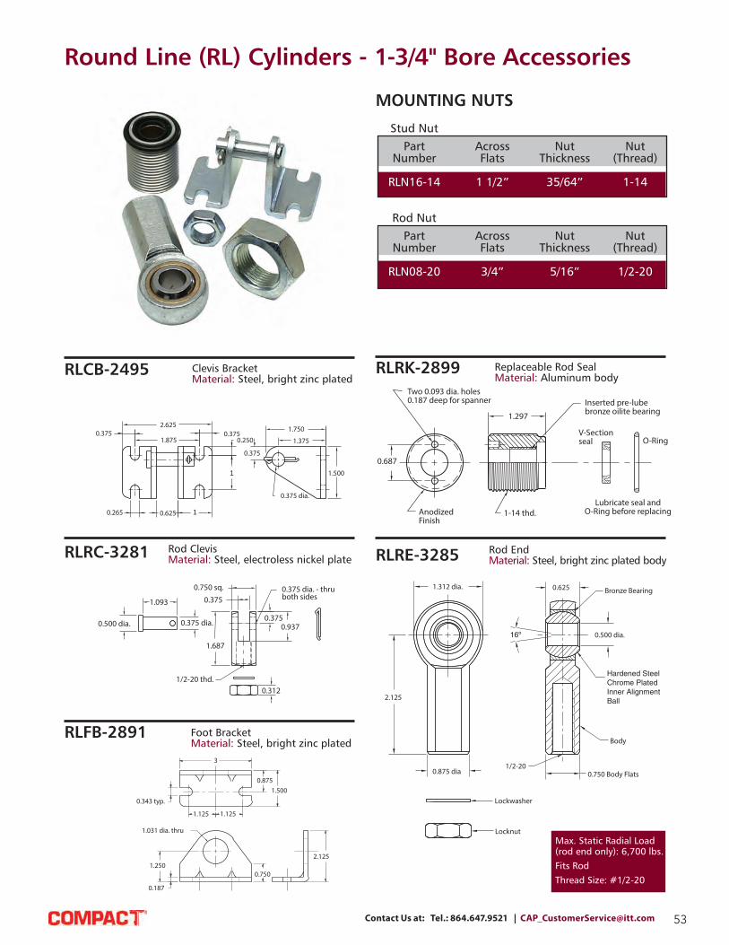
53Contact Us at: Tel.: 864.647.9521 | [email protected]
0.500 dia.
1.093
0.375 dia.
0.750 sq.
1.687
1/2-20 thd.
0.375
0.375
0.375 dia. - thruboth sides
0.937
0.312
0.265 0.625 1
1
1.8750.375
0.250
0.375
0.375 dia.
1.500
0.3752.625 1.750
1.375
3
0.8751.500
1.1251.125
0.343 typ.
1.031 dia. thru
1.250
0.187
0.750
2.125
Round Line (RL) Cylinders - 1-3/4" Bore Accessories
Rod Clevis
Material: Steel, electroless nickel plate
Clevis Bracket
Material: Steel, bright zinc plated
Foot Bracket
Material: Steel, bright zinc plated
1.312 dia.
2.125
0.875 dia
Lockwasher
Locknut
1/2-200.750 Body Flats
Bronze Bearing
0.500 dia.
0.625
Body
Rod End
Material: Steel, bright zinc plated body
Replaceable Rod Seal
Material: Aluminum body
Stud Nut
Part Across Nut Nut
Number Flats Thickness (Thread)
RLN16-14 1 1/2” 35/64” 1-14
Rod Nut
Part Across Nut Nut
Number Flats Thickness (Thread)
RLN08-20 3/4” 5/16” 1/2-20
MOUNTING NUTS
Max. Static Radial Load
(rod end only): 6,700 lbs.
Fits Rod
Thread Size: #1/2-20
RLCB-2495
RLRC-3281
RLFB-2891
RLRK-2899
RLRE-3285
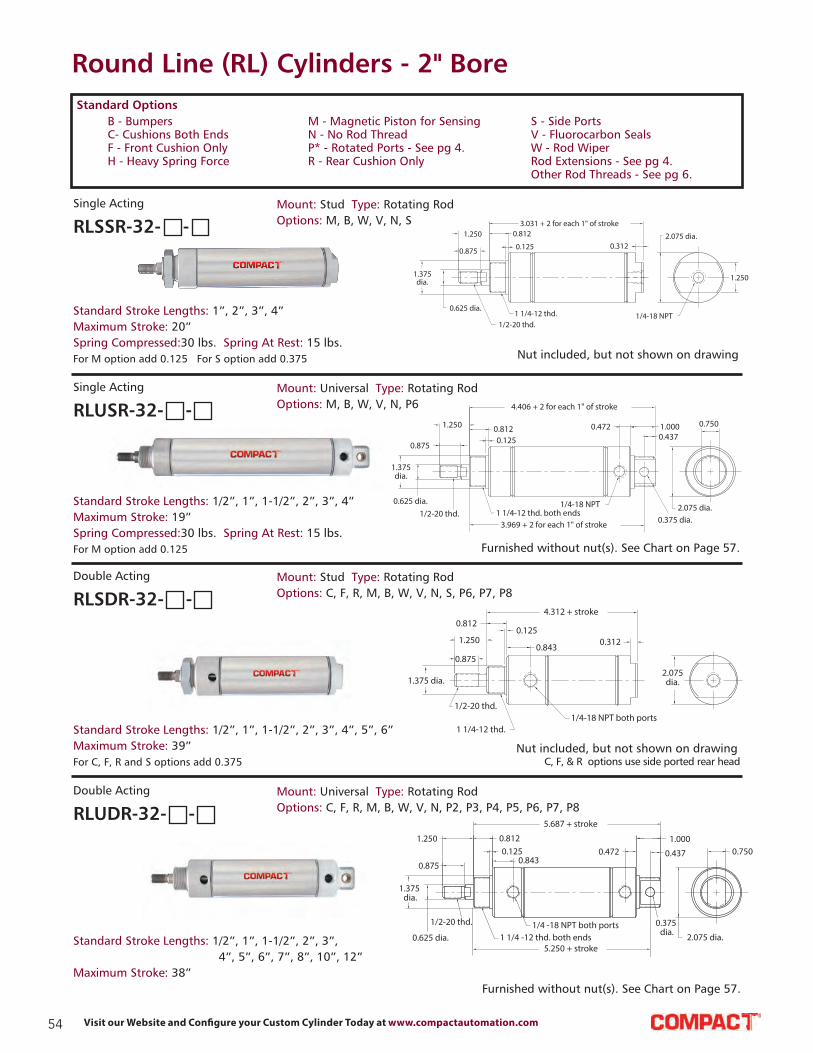
54 Visit our Website and Configure your Custom Cylinder Today at www.compactautomation.com
Round Line (RL) Cylinders - 2" Bore
1.375dia.
0.625 dia.
0.875
1.250 0.812
0.125
1/2-20 thd.1 1/4-12 thd.
3.031 + 2 for each 1" of stroke
0.3122.075 dia.
1/4-18 NPT
1.250
USR-32
0.625 dia.
1.375dia.
0.875
1.250 0.8120.125
1/2-20 thd. 1 1/4-12 thd. both ends
4.406 + 2 for each 1" of stroke
0.472 1.0000.437
1/4-18 NPT
0.375 dia.2.075 dia.
0.750
3.969 + 2 for each 1" of stroke
1.250
0.812
0.843
0.125
4.312 + stroke
0.312
1/2-20 thd.
1 1/4-12 thd.1/4-18 NPT both ports
2.075dia.1.375 dia.
0.875
UDR-32
1.250
0.875
0.625 dia.
1.375 dia.
1/2-20 thd.
1 1/4 -12 thd. both ends1/4 -18 NPT both ports
0.1250.812
0.843
5.687 + stroke
0.4721.000
0.437
0.375 dia.
0.750
2.075 dia.5.250 + stroke
C, F, & R options use side ported rear head
Nut included, but not shown on drawing
Nut included, but not shown on drawing
Furnished without nut(s). See Chart on Page 57.
Furnished without nut(s). See Chart on Page 57.
For M option add 0.125 For S option add 0.375
Standard Stroke Lengths: 1”, 2”, 3”, 4”
Maximum Stroke: 20”
Spring Compressed: 30 lbs. Spring At Rest: 15 lbs.
Mount: Stud Type: Rotating Rod
Options: M, B, W, V, N, SRLSSR-32- -
Single Acting
For M option add 0.125
Standard Stroke Lengths: 1/2”, 1”, 1-1/2”, 2”, 3”, 4”
Maximum Stroke: 19”
Spring Compressed: 30 lbs. Spring At Rest: 15 lbs.
Mount: Universal Type: Rotating Rod
Options: M, B, W, V, N, P6RLUSR-32- -
Single Acting
For C, F, R and S options add 0.375
Standard Stroke Lengths: 1/2”, 1”, 1-1/2”, 2”, 3”, 4”, 5”, 6”
Maximum Stroke: 39”
Mount: Stud Type: Rotating Rod
Options: C, F, R, M, B, W, V, N, S, P6, P7, P8RLSDR-32- -
Double Acting
Standard Stroke Lengths: 1/2”, 1”, 1-1/2”, 2”, 3”,
4”, 5”, 6”, 7”, 8”, 10”, 12”
Maximum Stroke: 38”
Mount: Universal Type: Rotating Rod
Options: C, F, R, M, B, W, V, N, P2, P3, P4, P5, P6, P7, P8RLUDR-32- -
Double Acting
B - Bumpers
C- Cushions Both Ends
F - Front Cushion Only
H - Heavy Spring Force
Standard Options
M - Magnetic Piston for Sensing
N - No Rod Thread
P* - Rotated Ports - See pg 4.
R - Rear Cushion Only
S - Side Ports
V - Fluorocarbon Seals
W - Rod Wiper
Rod Extensions - See pg 4.
Other Rod Threads - See pg 6.
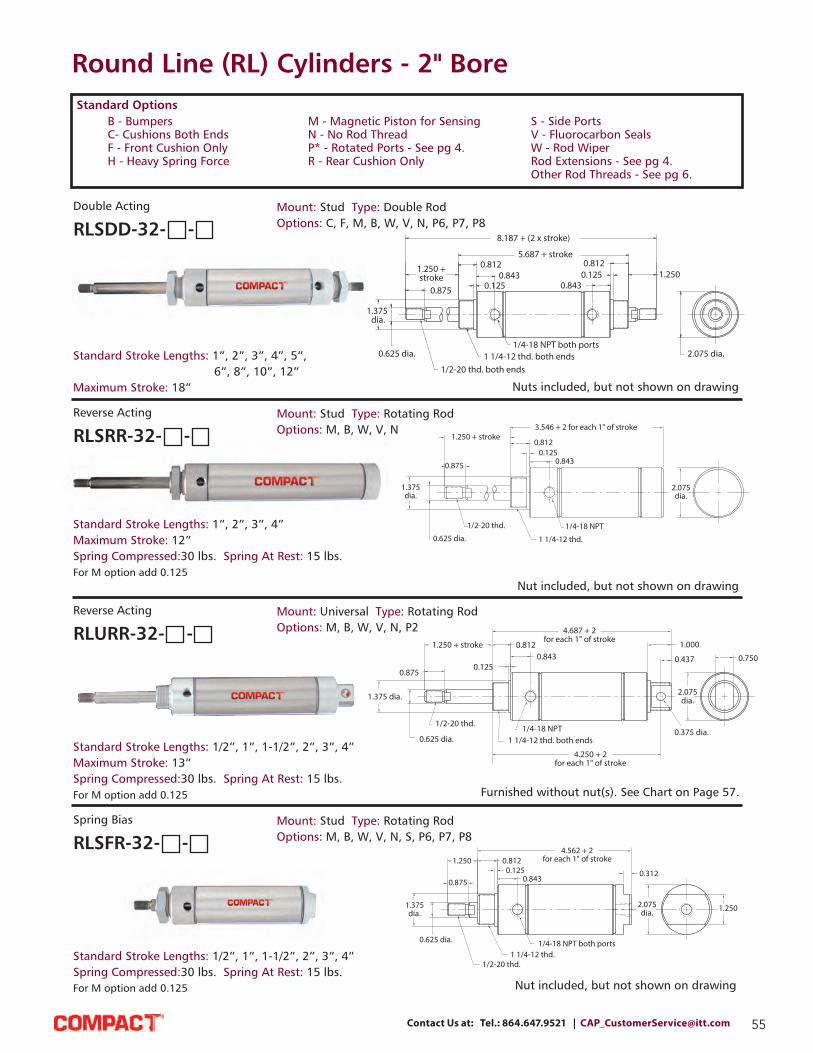
55Contact Us at: Tel.: 864.647.9521 | [email protected]
Round Line (RL) Cylinders - 2" Bore
SDD-32
1.375 dia.
0.625 dia.
0.875
1/2-20 thd. both ends1 1/4-12 thd. both ends
1/4-18 NPT both ports
1.250 +stroke
0.8120.843
0.125
8.187 + (2 x stroke)
5.687 + stroke
0.8430.1250.812
1.250
2.075 dia.
SDD-32
SRR-32
1.375dia.
0.625 dia.
0.875
1.250 + stroke0.812
0.8430.125
1/2-20 thd.
1 1/4-12 thd.
1/4-18 NPT
3.546 + 2 for each 1" of stroke
2.075dia.
1.375 dia.
0.625 dia.
0.875
1/2-20 thd.
1.250 + stroke
1 1/4-12 thd. both ends1/4-18 NPT
0.125
0.8120.843
4.687 + 2for each 1" of stroke
1.000
0.437
0.375 dia.
2.075dia.
0.750
4.250 + 2for each 1" of stroke
U R R -3 2
SFR-32
1.375dia.
0.625 dia.
1/2-20 thd.1 1/4-12 thd.
1/4-18 NPT both ports
0.875
1.2500.125
0.812
0.843
4.562 + 2for each 1" of stroke
0.312
2.075dia. 1.250
SFR-32
Nuts included, but not shown on drawing
Nut included, but not shown on drawing
Nut included, but not shown on drawing
Furnished without nut(s). See Chart on Page 57.
Standard Stroke Lengths: 1”, 2”, 3”, 4”, 5”,
6”, 8”, 10”, 12”
Maximum Stroke: 18”
Mount: Stud Type: Double Rod
Options: C, F, M, B, W, V, N, P6, P7, P8RLSDD-32- -
Double Acting
For M option add 0.125
Standard Stroke Lengths: 1”, 2”, 3”, 4”
Maximum Stroke: 12”
Spring Compressed: 30 lbs. Spring At Rest: 15 lbs.
Mount: Stud Type: Rotating Rod
Options: M, B, W, V, NRLSRR-32- -
Reverse Acting
For M option add 0.125
Standard Stroke Lengths: 1/2”, 1”, 1-1/2”, 2”, 3”, 4”
Maximum Stroke: 13”
Spring Compressed: 30 lbs. Spring At Rest: 15 lbs.
Mount: Universal Type: Rotating Rod
Options: M, B, W, V, N, P2RLURR-32- -
Reverse Acting
For M option add 0.125
Standard Stroke Lengths: 1/2”, 1”, 1-1/2”, 2”, 3”, 4”
Spring Compressed: 30 lbs. Spring At Rest: 15 lbs.
Mount: Stud Type: Rotating Rod
Options: M, B, W, V, N, S, P6, P7, P8RLSFR-32- -
Spring Bias
B - Bumpers
C- Cushions Both Ends
F - Front Cushion Only
H - Heavy Spring Force
Standard Options
M - Magnetic Piston for Sensing
N - No Rod Thread
P* - Rotated Ports - See pg 4.
R - Rear Cushion Only
S - Side Ports
V - Fluorocarbon Seals
W - Rod Wiper
Rod Extensions - See pg 4.
Other Rod Threads - See pg 6.

56 Visit our Website and Configure your Custom Cylinder Today at www.compactautomation.com
Round Line (RL) Cylinders - 2" Bore
1.375dia.
0.625 dia.
1/2-20 thd.
0.875
1.250 + stroke
1 1/4-12 thd. 1/4-18 NPT both ports
0.1250.812
0.8430
4.562 + 2for each 1" of stroke
0.312
2.075dia. 1.250
0.750
2.075dia.
0.437
0.375 dia.
1.000
0.472
1/2-20 thd. 1 1/4-12 thd. both ends1/4-18 NPT both ports
1.375dia.
0.625 dia.
0.875
1.2500.812
0.843
0.125
5.937 + 2for each 1" of stroke
5.500 + 2 for each 1" of stroke
UFR-32
1.375dia.
0.625 dia.1/2-20 thd.
0.875
1.250 + stroke
0.125
0.8430.812
1 1/4-12 thd. both ends1/4-18 NPT both ports
5.937 + 2 for each 1" of stroke0.472 1.000
0.437
2.075dia.
0.750
0.375 dia.
5.500 + 2 for each 1" of stroke
Nut included, but not shown on drawing
Furnished without nut(s). See Chart on Page 57.
Furnished without nut(s). See Chart on Page 57.
For S option add 0.375
Standard Stroke Lengths: 1/2”, 1”, 1-1/2”, 2”, 3”, 4”
Spring Compressed: 30 lbs. Spring At Rest: 15 lbs.
Mount: Stud Type: Rotating Rod
Options: M, B, W, V, N, S, P6, P7, P8RLSBR-32- -
Spring Bias
Standard Stroke Lengths: 1/2”, 1”, 1-1/2”, 2”, 3”, 4”
Spring Compressed: 30 lbs. Spring At Rest: 15 lbs.
Mount: Universal Type: Rotating Rod
Options: M, B, W, V, N, P2, P3, P4, P5, P6, P7, P8RLUFR-32- -
Spring Bias
Standard Stroke Lengths: 1/2”, 1”, 1-1/2”, 2”, 3”, 4”
Spring Compressed: 30 lbs. Spring At Rest: 15 lbs.
Mount: Universal Type: Rotating Rod
Options: M, B, W, V, N, P2, P3, P4, P5, P6, P7, P8RLUBR-32- -
Spring Bias
B - Bumpers
C- Cushions Both Ends
F - Front Cushion Only
H - Heavy Spring Force
Standard Options
M - Magnetic Piston for Sensing
N - No Rod Thread
P* - Rotated Ports - See pg 4.
R - Rear Cushion Only
S - Side Ports
V - Fluorocarbon Seals
W - Rod Wiper
Rod Extensions - See pg 4.
Other Rod Threads - See pg 6.
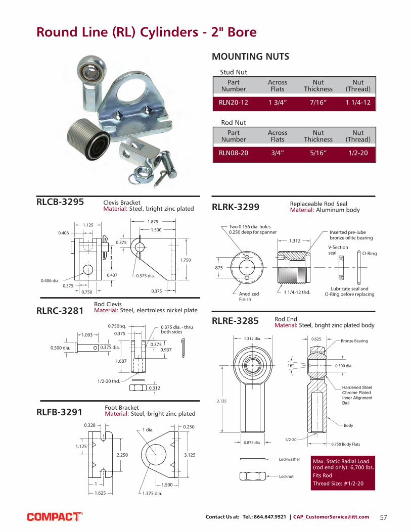
57Contact Us at: Tel.: 864.647.9521 | [email protected]
0.500 dia.
1.093
0.375 dia.
0.750 sq.
1.687
1/2-20 thd.
0.375
0.375
0.375 dia. - thruboth sides
0.937
0.312
Round Line (RL) Cylinders - 2" Bore
Rod Clevis
Material: Steel, electroless nickel plate
0.406 dia.
0.7500.375
0.437
1
0.406
1.125
0.375
0.375 dia.
0.375
1.750
1.500
1.875
Clevis Bracket
Material: Steel, bright zinc plated
Foot Bracket
Material: Steel, bright zinc plated
1.312 dia.
2.125
0.875 dia
Lockwasher
Locknut
1/2-200.750 Body Flats
Bronze Bearing
0.500 dia.
0.625
Body
Rod End
Material: Steel, bright zinc plated body
Replaceable Rod Seal
Material: Aluminum body
Stud Nut
Part Across Nut Nut
Number Flats Thickness (Thread)
RLN20-12 1 3/4” 7/16” 1 1/4-12
Rod Nut
Part Across Nut Nut
Number Flats Thickness (Thread)
RLN08-20 3/4” 5/16” 1/2-20
MOUNTING NUTS
RLCB-3295
RLRC-3281
RLFB-3291
RLRK-3299
RLRE-3285
Max. Static Radial Load
(rod end only): 6,700 lbs.
Fits Rod
Thread Size: #1/2-20

58 Visit our Website and Configure your Custom Cylinder Today at www.compactautomation.com
Round Line (RL) Cylinders - 2-1/2" Bore
1.500 dia.
0.625 dia.
1/2-20 thd.
1 3/8-12 thd.1/4-18 NPT both ports
0.8751.250
0.812 0.8430.125
4.312 + stroke
0.312 2.600 dia.
1.750
UDR-40
1.500 dia.
0.625 dia. 1/2-20 thd.
0.8751.250
0.8120
0.8430.125
5.687 + stroke
0.468
10.125
0.437
1/4-18 NPT both ports 1 3/8-12 thd. both ends
0.375 dia.
2.600dia.
0.750
5.250 + stroke
1.250 +stroke
0.875
5.687 + stroke0.812
1.500 dia.0.625 dia.
0.125
8.187 + (2 x stroke)
0.8430.125
0.8121.250
0.875
1/4-18 NPT both ports1 3/8-12 thd. both ends
1/2-20 thd.both ends
2.600 dia.0.843
Bumpers are standard For M option add 0.312 For C, F, R and S option add 0.375
Nut included, but not shown on drawing
Nut included, but not shown on drawing
Furnished without nut(s). See Chart on Page 59.
Standard Stroke Lengths: 1”, 2”, 3”, 4”, 5”, 6”
Maximum Stroke: 39”
Mount: Stud Type: Rotating Rod
Options: C, F, R, M, W, V, N, S, P6, P7, P8RLSDR-40- -
Double Acting
Bumpers are standard For M option add 0.312
Standard Stroke Lengths: 1”, 2”, 3”, 4”, 5”,
6”, 7”, 8”, 10”, 12”
Maximum Stroke: 38”
Mount: Universal Type: Rotating Rod
Options: C, F, R, M, W, V, N, P2, P3, P4, P5, P6, P7, P8RLUDR-40- -
Double Acting
Bumpers are standard For M option add 0.312
Standard Stroke Lengths: 1”, 2”, 3”, 4”, 5”,
6”, 7”, 8”, 10”, 12”
Maximum Stroke: 18”
Mount: Stud Type: Rotating Rod
Options: C, F, M, W, V, N, P6, P7, P8RLSDD-40- -
Double Acting
B - Bumpers
C- Cushions Both Ends
F - Front Cushion Only
H - Heavy Spring Force
Standard Options
M - Magnetic Piston for Sensing
N - No Rod Thread
P* - Rotated Ports - See pg 4.
R - Rear Cushion Only
S - Side Ports
V - Fluorocarbon Seals
W - Rod Wiper
Rod Extensions - See pg 4.
Other Rod Threads - See pg 6.
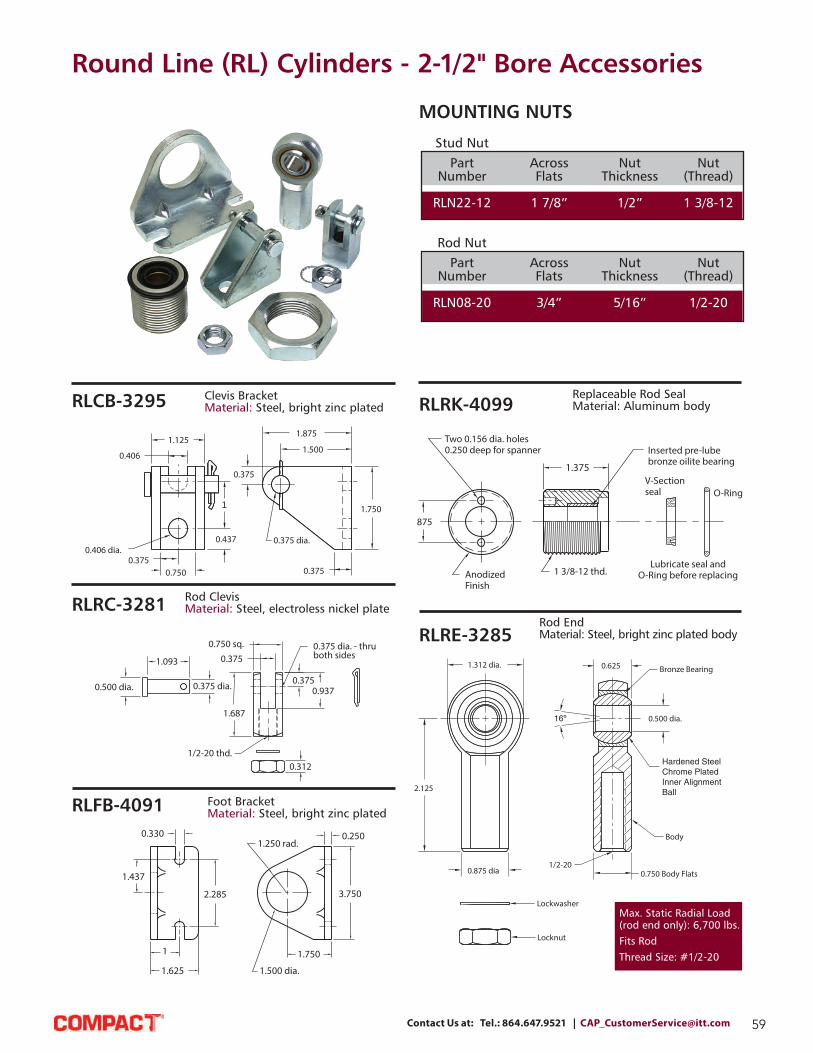
59Contact Us at: Tel.: 864.647.9521 | [email protected]
0.500 dia.
1.093
0.375 dia.
0.750 sq.
1.687
1/2-20 thd.
0.375
0.375
0.375 dia. - thruboth sides
0.937
0.312
Round Line (RL) Cylinders - 2-1/2" Bore Accessories
Rod Clevis
Material: Steel, electroless nickel plate
0.406 dia.
0.7500.375
0.437
1
0.406
1.125
0.375
0.375 dia.
0.375
1.750
1.500
1.875
Clevis Bracket
Material: Steel, bright zinc plated
1.437
1.625
1
2.285
0.330
1.500 dia.
1.250 rad.
1.750
3.750
0.250
1.312 dia.
2.125
0.875 dia
Lockwasher
Locknut
1/2-200.750 Body Flats
Bronze Bearing
0.500 dia.
0.625
Body
Rod End
Material: Steel, bright zinc plated body
Replaceable Rod Seal
Material: Aluminum body
Foot Bracket
Material: Steel, bright zinc plated
Stud Nut
Part Across Nut Nut
Number Flats Thickness (Thread)
RLN22-12 1 7/8” 1/2” 1 3/8-12
Rod Nut
Part Across Nut Nut
Number Flats Thickness (Thread)
RLN08-20 3/4” 5/16” 1/2-20
MOUNTING NUTS
RLCB-3295
RLRC-3281
RLFB-4091
RLRK-4099
RLRE-3285
Max. Static Radial Load
(rod end only): 6,700 lbs.
Fits Rod
Thread Size: #1/2-20

60 Visit our Website and Configure your Custom Cylinder Today at www.compactautomation.com
Round Line (RL) Cylinders - 3" Bore
2.000
3.125dia.
3/8-18 NPTboth ports
1 1/2-12 thd.
5/8-18 thd.
0.750dia.
1.625dia.
1.2501.625
0.992
0.7070.125
4.875 + stroke
0.313
0.992
0.7070.125
1.625
1.250
1.625dia.
0.750dia.
5/8-18 thd. 1 1/2-12 thd. both ends
3/8-18 NPT both ports
0.500 dia.
0.625
0.1870.510
1.4386.750 + stroke
0.875
3.125dia.
6.125 + stroke
Nuts included, but not shown on drawing
Nut included, but not shown on drawing
Furnished without nut(s). See Chart on Page 61.
Bumpers are standard No additional length for bumpers For S option add 0.437
Standard Stroke Lengths: 1”, 2”, 3”, 4”, 5”, 6”
Maximum Stroke: 34”
Mount: Stud Type: Rotating Rod
Options: M, W, V, N, S, P6, P7, P8RLSDR-48- -
Double Acting
Bumpers are standard No additional length for bumpers For S option add 0.437
Standard Stroke Lengths: 1”, 2”, 3”, 4”, 5”, 6”, 7”, 8”, 10”, 12”
Maximum Stroke: 32”
Mount: Universal Type: Rotating Rod
Options: M, W, V, N, P2, P3, P4, P5, P6, P7, P8RLUDR-48- -
Double Acting
Bumpers are standard No additional length for bumpers
Standard Stroke Lengths: 1”, 2”, 3”, 4”, 5”, 6”, 7”, 8”, 10”, 12”
Maximum Stroke: 15”
Mount: Stud Type: Rotating Rod
Options: M, W, V, N, P6, P7, P8RLSDD-48- -
Double Acting
B - Bumpers
C- Cushions Both Ends
F - Front Cushion Only
H - Heavy Spring Force
Standard Options
M - Magnetic Piston for Sensing
N - No Rod Thread
P* - Rotated Ports - See pg 4.
R - Rear Cushion Only
S - Side Ports
V - Fluorocarbon Seals
W - Rod Wiper
Rod Extensions - See pg 4.
Other Rod Threads - See pg 6.

61Contact Us at: Tel.: 864.647.9521 | [email protected]
Round Line (RL) Cylinders - 3" Bore Accessories
0.265
3.8752.625
0.875
0.500dia.
1.250
2.250
1.750 0.250
0.500
1.750
Clevis Bracket
Material: Steel, bright zinc plated
Foot Bracket
Material: Steel, bright zinc plated
1
4.375
1.625 dia.
3.1251.890
0.330 typ.1.625
0.250
1.750
3.500
1.500 dia.
2.500
1.000 dia
Lockwasher
Locknut
5/8-180.875 Body Flats
Bronze Bearing
0.625 dia.
0.750
Body
Rod End
Material: Steel, bright zinc plated body
Replaceable Rod Seal
Material: aluminum body
Rod Clevis
Material: Steel, electroless nickel plate
0.498 dia.
1.060
1.375
0.500 dia. - thruboth sides
2.750
1 sq.0.505
0.500
1.500
0.375
5/8-18 thd.
Stud Nut
Part Across Nut Nut
Number Flats Thickness (Thread)
RLN24-12 2 1/4” 1/2” 1 1/2-12
Rod Nut
Part Across Nut Nut
Number Flats Thickness (Thread)
RLN10-18 15/16” 3/8“ 5/8-18
MOUNTING NUTS
RLCB-4895
RLRC-4881
RLFB-4891
RLRK-4899
RLRE-4885
Max. Static Radial Load
(rod end only): 7,400 lbs.
Fits Rod
Thread Size: #5/8-18

62 Visit our Website and Configure your Custom Cylinder Today at www.compactautomation.com
Round Line (RL) Cylinders - Position Sensors
0.340.20
0.40
0.65
0.391.18
0.28
0.25 LED
approx. sensingpoint
Reed Switch Part No.
RLRPS-P3 Sourcing Switch with 3 m Wire Leads
RLRPS-P8Q Sourcing Switch with 8 mm Male QC 6” Pigtail
RLRPS-N3 Sinking Switch with 3 m Wire Leads
RLRPS-N8Q Sinking Switch with 8 mm Male QC 6” Pigtail
RLRPS-S3 Simple Switch (2-Wire) with 3 m Wire Leads
RLRPS-S8Q Simple Switch (2-Wire) with 8 mm Male QC 6” Pigtail
RLCPS-C8Q5 Mating Cable Assembly, 8 mm Female QC with 5 m Leads
GMR Switch Part No.
RLGPS-P3 Sourcing Switch with 3 m Wire Leads
RLGPS-P8Q Sourcing Switch with 8 mm Male QC 6” Pigtail
RLGPS-N3 Sinking Switch with 3 m Wire Leads
RLGPS-N8Q Sinking Switch with 8 mm Male QC 6” Pigtail
RLCPS-C8Q5 Mating Cable Assembly, 8 mm Female QC with 5 m Leads
Accessories
Our Universal Mounting Bracket is designed for use with both a RLGPS or RLRPS Sensors on any bore cylinder equipped with a magnetic piston. Allen wrench is included.
Universal Mounting Bracket RLUC-0848
Dimensions All RLGPS and RLRPS Position Sensors
Magnetic Piston -M Compact’s Round Line stainless steel cylinders that are equipped with a magnetic piston (M) can use either a solid-state device or a reed switch to sense the position of the piston. As the piston’s magnet passes beneath the sensor, the magnetic field will trigger the switch creating an output signal. These small durable switches feature quick response times, low power consumption and offering reliable operation. Adding a magnet to the piston may increase the overall length of the cylinder. See the specific cylinder to determine if the length will increase with the magnetic piston (M). Compact’s RLGPS Sensor is a solid-state device that exhibits a change in electrical resistance when subjected to a magnetic field created by the magnet on the piston. This design offers a highly durable, sensitive switch with low power consumption and fast response times.
Compact’s RLRPS Reed Switch is a single-pole, single throw (SPST) Normally Open electronic switch. When the magnet field of piston’s magnet passes beneath the switch, a signal is sent indicating the location of the piston.

63Contact Us at: Tel.: 864.647.9521 | [email protected]
Blue~
Brown
~Power
Load
MAI
NC
IRC
UIT
Blue
Black
Load
Brown
Power
CIR
CU
ITM
AIN
Blue
Black Load
Brown
PowerBlue
Black
Brown
LoadPower
(+) Brown
(NC)
(-) Blue1
Blue
Black
Brown
LoadPower
3
4
(+) Brown
(out) Black
(-) Blue1 3
4
Blue~
Brown
~Power
Load
MAI
NC
IRC
UIT
Blue
Black
Load
Brown
Power
CIR
CU
ITM
AIN
Blue
Black Load
Brown
PowerBlue
Black
Brown
LoadPower
(+) Brown
(NC)
(-) Blue1
Blue
Black
Brown
LoadPower
3
4
(+) Brown
(out) Black
(-) Blue1 3
4
Characteristic/Type RLRPS-S RLGPS-N RLGPS-P RLRPS-N RLRPS-P
Switching Logic SPST Normally-Open Solid State Output, Solid State Output, SPST Normally-Open SPST Normally-Open
Normally-Open Normally-Open
Sensor Type Reed Switch NPN Current Sinking PNP Current Sourcing Reed Switch NPN Reed Switch PNP
Operating Voltage RLRPS-S3: 5 to 120 VAC
RLRPS-S8Q: 5 to 60 VAC/DC
Switching Current 100 mA max. 200 mA max. 200 mA max. 250 mA max. 250 mA max.
Switching Rating 10 W max. 6 W max. 6 W max. 10 W max. 10 W max.
Current Consumption - 7.5 mA max. @ 24 V 7.5 mA max. @ 24 V 10 mA max. @ 24 V 10 mA max. @ 24 V
(Switch Active) (Switch Active) (Switch Active) (Switch Active)
Voltage Drop
2.5 V max. @
0.5 V max. @ 0.5 V max. @ 0.5 V max. @ 0.5 V max. @
40 mA DC
200 mA 200 mA 550 mA 550 mA
(Resistive Load) (Resistive Load) (Resistive Load) (Resistive Load)
Leakage Current - 0.01 mA max. 0.01 mA max. - -
Indicator Red LED Red LED Green LED Red LED Green LED
Cable 2.8§, 2C, 2.8§, 3C, 2.8§, 3C, 2.8§, 3C, 2.8§, 3C,
Oil-Resistant PVC Oil-Resistant PVC Oil-Resistant PVC Oil-Resistant PVC Oil-Resistant PVC
Sensitivity 60 G 40 ~ 750 G 40 ~ 750 G 60 G 60 G
Max. Switching Frequency 200 Hz 5,000 Hz 5,000 Hz 1,000 Hz 1,000 Hz
Temperature Range 14 to 158°F (-10 to 70°C) 14 to 158°F (-10 to 70°C) 14 to 158°F (-10 to 70°C) 14 to 158°F (-10 to 70°C) 14 to 158°F (-10 to 70°C)
Shock 30 G 50 G 50 G 30 G 30 G
Vibration 9 G 9 G 9 G 9 G 9 G
Enclosure Classification IP 67 (NEMA 6) IP 67 (NEMA 6) IP 67 (NEMA 6) IP 67 (NEMA 6) IP 67 (NEMA 6)
Protection Circuit - Power Source Reverse Power Source Reverse - -
Polarity; Surge Polarity; Surge
Suppression Suppression
5 to 28 VDC 5 to 28 VDC 5 to 30 VDC 5 to 30 VDC
Quick Connector
2-Wire QD Wiring 3-Wire QD Wiring
Round Line (RL) Cylinders - Switch Selection
RLRPS-S RLGPS-N RLGPS-P RLRPS-N RLRPS-P
The Compact stainless steel cylinders designated with an internal magnet on the piston can be used to trigger both the Reed or GMR sensors. The position of the piston can be accurately sensed by the sensors as the magnetic field of the magnet passes beneath the sensor, creating a feedback signal. The addition of the -M option may add overall length to the cylinder.
See the specific cylinder data for availability and details of the overall length adder.

64 Visit our Website and Configure your Custom Cylinder Today at www.compactautomation.com
F low Controls - Unique Inch to Metric Combinations
3 Flow Paths
• Metered Output• Free Flow Input
Style “MO” Meter OUT
• Metered Input• Free Flow Output
Style “MI” Meter In
• Metered Input• Metered Output
Style “NV” Needle ValveMeter Both Ways
• A unique needle design minimizes turbulence and improves flow control ability.• A super fine pitch needle thread provides the finest adjustment available.• Captive needle cannot be adjusted out of the housing.
Precision Control
Sizes Needle PitchNumber of
Turns
# 10-32 80 TPI 6
1/8NPTF 60 TPI 8
1/4NPTF 56 TPI 8
Model Numbers*
Knob Option Available on Inch Versions: Add Suffix “K” Example: MO18K
Barb Fitting for #10-32 or M5 only: Add Suffix “B” Example: MO10B or MO10BK with Knob
Port Thread
“MO” Color Code: Black “MI” Color Code: Red “NV” Color Code: Silver
Model #Male
Thread
Female
ThreadModel #
Male
Thread
Female
ThreadModel #
Male
Thread
Female
Thread
# 10-32 M5MO10 # 10-32 # 10-32 MI10 # 10-32 # 10-32 NV10 # 10-32 # 10-32
MO10-5 # 10-32 M5 MI10-5 # 10-32 M5 NV10-5 # 10-32 M5
1/8-27NPTF
G1/8
MO18 1/8NPTF 1/8NPTF MI18 1/8NPTF 1/8NPTF NV18 1/8NPTF 1/8NPTF
MO18-G18 1/8NPTF G1/8 MI18-G18 1/8NPTF G1/8 NV18-G18 1/8NPTF G1/8
1/4-18NPTF
G1/4
MO14 1/4NPTF 1/4NPTF MI14 1/4NPTF 1/4NPTF NV14 1/4NPTF 1/4NPTF
MOG14 G1/4 G1/4 MIG14 G1/4 G1/4 NVG14 G1/4 G1/4
Materials and Technical Data
Size HousingInner
HousingNeedle Seals
Pressure
Ratings
Captive
Needle360° Swivel
Gasket
Material
M5 # 10-32Nickel Plated
BrassNickel Plated
BrassStainless Steel
Buna-N
0°F to 200°F
-15°C to 90°C
0 to 175 PSI
0 to 12 BARYes
Yes- Prior to
tightening
1/8NPTF and
1/4NPTF swivel
after mounting
Nylon
0°F to 200°F
-15°C to 90°C1/8 and 1/4Anodized
Aluminum
Other available sizes of Flow Controls are available in our Compact Automation Inch Series catalog, Pg. 91-92 located at:
https://www.compactautomation.com/Inch_Catalog

65Contact Us at: Tel.: 864.647.9521 | [email protected]
Rod End Alignment Coupler Inch Sizes
A DIA
E
1º MAX
C FLAT
K HEX(FOR SOCKET
KEY)
J (OFF CENTER ADJUSTMENT)
F
G THREAD
D
B DIA
H TAP
BoreRod
ThreadPart No.
Female
Thread
Male
Thread
H
Female
Thread x
Depth
G
Male
Thread
A B C D E F J K
Unit
Weight
(oz.)
Axial
Load
Ratings
(lbs.)
1/2" 9/16" 5/8"
#10-32ACFF10 FINE FINE #10-32 X 5/16 #10-32
9/16 5/16 1/4 11/32 9/16 13/32 1/64 3/32 0.5 180ACCF10 FINE COARSE #10-32 X 5/16 #10-24
3/4"
7/8"1/4-28 ACCF14 FINE COARSE 1/4-28 X 1/2 1/4-20 15/16 1/2 7/16 13/32 13/16 9/16 1/32 1/8 1.6 180
1-1/16” 5/16-24ACCF516 FINE COARSE 5/16-24 X 5/8 5/16-18
15/16 1/2 7/16 11/16 13/16 9/16 1/64 5/32 1.6 580ACFF516 FINE 5/16-24 X 5/8 5/16-24
1-1/4" 1-1/2"
3/8-24ACFF38 FINE 3/8-24 X 5/8 3/8-24
1-1/8 5/8 9/16 9/16 1-1/32 3/4 1/32 5/32 3.2 580ACCF38 FINE COARSE 3/8-24 X 5/8 3/8-16
7/16-20ACCF716 FINE COARSE 7/16-20 X 13/16 1/2-12
1-9/16 3/4 11/16 3/4 1-3/8 1-1/8 1/16 1/4 8.8 1690ACFF716 FINE 7/16-20 X 13/16 1/2-20
3" 5/8"-18ACCC58 FINE COARSE 5/8-18 X 1.0 5/8-11
2-1/4 1.0 15/16 15/16 1-3/4 1-1/2 1/16 5/16 24.0 3220ACCF58 FINE 5/8-18 X 1.0 5/8-18
Material: Hardened steel
Finish: Black Oxide Finish
Maximum Temperature Rating:
200ºF (93.3ºC)
NOTE: Do not use alignment couplers
on pivoting applications.
All dimensions are in inches.
THIRD ANGLE
PROJECTION
Rod
ThreadPart No.
H
Female Thread
x Depth
G
Male
Thread
A B C D E F J
K
mm
(inch)
Unit
Weight
(oz.)
Axial
Load
Ratings
(lbs.)
#10-32 WACM5-F10 #10-32 X 5/16 M5 X 0,8 14,0 7,9 6,35 8,0 15,2 11,0 0,4 3,0 (.118) 11,4 815
1/4-28 WACM6-F16 1/4-28 X 1/2 M6 X 1 24,0 12,7 11,1 9,7 21,5 15,0 0,8 4,0 (.157) 45,4 2045
5/16-24 WACM8-F516 5/16-24 X 5/8 M8 X 1,25 24,0 12,7 11,1 11,7 22,5 16,0 0,4 5,0 (.197) 45,4 2580
3/8-24 WACM10-F38 3/8-24 X 5/8 M10 X 1,5 28,0 15,9 14,3 16 26,5 20,0 0,8 7,0 (.276) 90,7 3700
7/16-20 WACM12-F716 7/16-20 X 13/16 M12 X 1,75 39,0 19,1 17,5 17,9 36,5 30,0 1,6 6,35 (1/4) 250,0 7540
1/2-20 WACM12-F12 1/2-20 X 13/16 M12 X 1,75 39,0 19,1 17,5 17,9 36,5 30,0 1,6 6,35 (1/4) 250,0 7540
Combination Sizes (Inch & Metric)
All dimensions are in millimeters expect where noted.
Other available sizes of Flow Controls are available in our Compact Automation Inch Series catalog, Pg. 89-90 located at:
https://www.compactautomation.com/Inch_Catalog

66 Visit our Website and Configure your Custom Cylinder Today at www.compactautomation.com
Determination of the suitability of any information or product for the application contemplated by any user or the manner of that use is the sole responsibility of the user.
Compact Automation Products, LLC reserves the right to improve or change designs without notice.
All orders are subject to acceptance by the factory sales department.
Compact Automation Products, LLC agrees to repair or replace to the original purchaser any standard parts or products for a period of 12 months from date of shipment which Compact Automation Products, LLC determines upon inspection to be defective in workmanship or material. Wear components including but not limited to seals and bearings are excluded from this warranty.
Under no circumstance may merchandise be returned without written authorization from the factory.
This warranty is void in the event the product has been tampered with, altered, or serviced by unauthorized personnel.
Compact Automation Products, LLC's total responsibility for any claims, damages, losses or liabilities related to the product covered thereunder shall not exceed the purchase price of such product. In no event shall Compact Automation Products, LLC be liable for any special, indirect, incidental or consequential damages of any character, including but not limited to loss of use of productive facilities or equipment, lost profit, property damage, transportation, installation or removal or lost production whether suffered by purchaser or third party. Compact Automation Products, LLC disclaims all liability for any and all cost, claims demands, charges, expenses, and other damages, either direct or indirect, incident to all property damage arising out of any cause of action based on strict liability. This warranty gives you specific legal rights and you may have other rights, which vary from state to state.
Special Conditions and Limited Warranty

68 Visit our Website and Configure your Custom Cylinder Today at www.compactautomation.com
Notes

Compact Automation Products, LLC105 Commerce WayWestminster, SC 29693Tel: 864.647.9521www.compactautomation.com
CAPSS1494R2 07/2021
An ITT Company
Top Related