


Languages
Pages
Legal


Rexroth IndraControl VCP 20
IndustrialHydraulics
Electric Drivesand Controls
Linear Motion and Assembly Technologies Pneumatics
ServiceAutomation
MobileHydraulics
Rexroth ADF Main Spindle Motors
R911271431Edition 01
Project Planning Manual
About this documentation
Title ADF Main Spindle Motors
Type of documentation Project Planning Manual
Doc. Type DOK-MOTOR*-ADF********-PRJ1-EN-E1,44
Internal file reference • Mappe 7a
• ADF-Pj.pdf
• 209-0042-4132-00
Reference This electronic document is based on the hardcopy document with documentdesig.: DOK-MOTOR*-ADF********-PRJ1-EN-P • 06.96
The purpose of thisdocument
This document
• serves to introduce ADF main spindle motors
• offers technial explanations of the structural features of main spindle mo-tors
• assists in selecting the correct main spindle motor for a specific application
• outlines the technical data of main spindle motors
Change sequence
Copyright ©INDRAMAT GmbH, 1996
Copying this document, and giving it to others and the use or communicationof the contents thereof without express authority are forbidden. Offenders areliable for the payment of damages. All rights are reserved in the event of thegrant of a patent or the registration of a utility model or design (DIN 34-1).
The electronic documentation (E-doc) may be copied as often as needed ifsuch are to be used by the consumer for the purpose intended.
Validity All rights are reserved with respect to the content of this documentation andthe availability of the product.
Published by INDRAMAT GmbH • Bgm.-Dr.-Nebel-Str. 2 • D-97816 Lohr a. MainTelefon 09352/40-0 • Tx 689421 • Fax 09352/40-4885
Dept. ENA (MR, FS)
Document codeof present editions
Release date
Comment
DOK-MOTOR*-ADF********-PRJ1-EN-PDOK-MOTOR*-ADF********-PRJ1-EN-E1,44
June 96Mar. 97
1st edition1st edition E-doc
• DOK-MOTOR*-ADF********-PRJ1-EN-E1,44 • 03.97 2
Table of Contents
Table of Contents Page
1. Introducing Main Spindle Motors 5
2. Technical Explanations 8
2.1. Ambient Conditions ..........................................................................8
2.2. Mechanical Features ......................................................................11
2.3. Electrical Features .........................................................................16
3. ADF 100 18
3.1. Technical Data ...............................................................................18
3.2. Dimensional Data - ADF 100 .........................................................20
3.3. Type Codes ....................................................................................22
4. ADF 132 23
4.1. Technical Data ...............................................................................23
4.2. Holding Brake ................................................................................25
4.3. Dimensional Data - ADF 132 .........................................................26
4.4. Type Codes ....................................................................................28
5. ADF 160 29
5.1. Technical Data ...............................................................................29
5.2. Holding brake .................................................................................31
5.3. Dimensional Data - ADF 160 .........................................................32
5.4. Type Codes ....................................................................................34
6. Electrical Connections 35
6.1. Terminal Diagram - ADF 100 .........................................................35
6.2. Terminal Diagram - ADF 132 and ADF 160 ...................................37
6.3. Table - Motor power cable .............................................................39
6.4. Terminal Diagram - Motor Feedback .............................................41
6.5. Type Designations .........................................................................43
7. Condition at Delivery 44
8. Identifying the Merchandise 45
• DOK-MOTOR*-ADF********-PRJ1-EN-E1,44 • 03.97
Table of Contents
9. Storage, Transportation and Handling 47
10. Mounting and Installation Guidelines 49
11. Commissioning 50
12. Service Guidelines 51
12.1. Contacting Customer Service ........................................................51
12.2. Repair Report Card ........................................................................52
13. Index 53
• DOK-MOTOR*-ADF********-PRJ1-EN-E1,44 • 03.97
1. Introducing Main Spindle Motors
1. Introducing Main Spindle Motors
Applications Main spindle motors of the ADF series are used as liquid-cooled mainspindle drives and as servo drives in such applications as, for example, toolmachines. ADF motors have been tried and proven in printing, textile andplastics injection moulding machines.
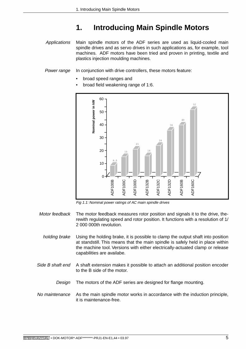
Power range In conjunction with drive controllers, these motors feature:
• broad speed ranges and• broad field weakening range of 1:6.
Fig 1.1: Nominal power ratings of AC main spindle drives
Motor feedback The motor feedback measures rotor position and signals it to the drive, the-rewith regulating speed and rotor position. It functions with a resolution of 1/2 000 000th revolution.
holding brake Using the holding brake, it is possible to clamp the output shaft into positionat standstill. This means that the main spindle is safely held in place withinthe machine tool. Versions with either electrically-actuated clamp or releasecapabilities are availabe.
Side B shaft end A shaft extension makes it possible to attach an additional position encoderto the B side of the motor.
Design The motors of the ADF series are designed for flange mounting.
No maintenance As the main spindle motor works in accordance with the induction principle,it is maintenance-free.
AD
F10
0B
AD
F10
0C
AD
F10
0D
AD
F13
2B
AD
F13
2C
AD
F13
2D
AD
F16
0B
AD
F16
0C
N
omin
al p
ower
in k
W
8.5
0
10
20
30
40
50
60
15
21
16
24
36
40
52
• DOK-MOTOR*-ADF********-PRJ1-EN-E1,44 • 03.97 5

1. Introducing Main Spindle Motors
g
Output shaft
with key
with shaft sealing rin
heavy-dutybearing assembly(ADF132/ADF160)
with spindlebearing assembly(ADF132)
EXADF100
ADF 100
1
2
3
6
4
7
Output shaft
Power connector withintegral connection for• motor NTC thermistor• blocking brake
Motor feedback connection
Integral blocking brake
Side B shaft end
Clockwise rotational direction
Coolant inlet and outlet
1
2
3
4
5
6
7
• DOK-MOTOR*-ADF********-PRJ1-EN-E1,44 • 03.97 6

1. Introducing Main Spindle Motors
Fig 1.2: Main spindle motors - explanations of definitions
Power connection
A
B
R
L
Holding brake
R, S, S
1
Balance classes
Output directioncan be selected
ADF132, 160
bottom
top
right
left
side A
1
6
side B
4
2 3
5
7
EXADF132
• DOK-MOTOR*-ADF********-PRJ1-EN-E1,44 • 03.97 7

2. Technical Explanations
2. Technical Explanations
2.1. Ambient Conditions
Installaton elevation,ambient temperature
ADF main spindle motors can be operated at any elevation because theyare liquid cooled. The values listed in the document “AC Main Spindle Driveswith Regulated Main Spindle Motors 2AD and ADF; Selection Data” (doc.no. 209-0042-4133 EN) are only dependent on maintaining the cooling para-meters of the coolant.
The ambient temperature range of 0° to 45° C must be maintained to gua-rantee a safe operation of the motor feedback.
Protection category The ADF motors are, as per DIN 40050, protected by their housing andcoverings against:
• contact with live or moving parts of the motor (contact guard), • penetration by extrinsic objects • or the seeping in of water.
The protection categories are indicated by the abbreviation IP (InternationalProtection) and two digits for the protection grade, as, for example, IP 65.
The first digit denotes the protection grade for contact and penetration byextrinsic objects (see Figure 2.1).
The second digit denotes the protection grade for water (see Figure 2.2).
Figure 2.3 lists the range of protection categories for main spindle motors.
• DOK-MOTOR*-ADF********-PRJ1-EN-E1,44 • 03.97 8
2. Technical Explanations
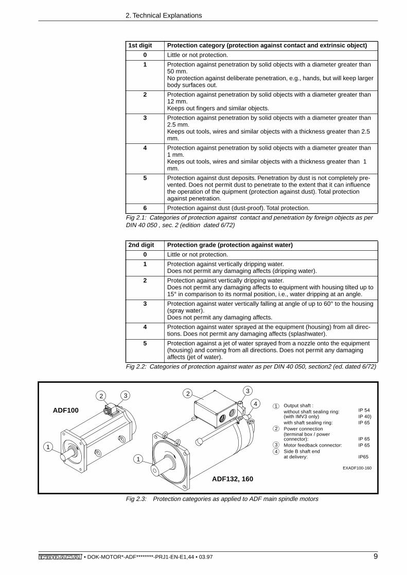
Fig 2.1: Categories of protection against contact and penetration by foreign objects as per DIN 40 050 , sec. 2 (edition dated 6/72)
Fig 2.2: Categories of protection against water as per DIN 40 050, section2 (ed. dated 6/72)
Fig 2.3: Protection categories as applied to ADF main spindle motors
1st digit Protection category (protection against contact and extrinsic object)
0 Little or not protection.
1 Protection against penetration by solid objects with a diameter greater than 50 mm.No protection against deliberate penetration, e.g., hands, but will keep larger body surfaces out.
2 Protection against penetration by solid objects with a diameter greater than 12 mm.Keeps out fingers and similar objects.
3 Protection against penetration by solid objects with a diameter greater than 2.5 mm.Keeps out tools, wires and similar objects with a thickness greater than 2.5 mm.
4 Protection against penetration by solid objects with a diameter greater than 1 mm.Keeps out tools, wires and similar objects with a thickness greater than 1 mm.
5 Protection against dust deposits. Penetration by dust is not completely pre-vented. Does not permit dust to penetrate to the extent that it can influence the operation of the quipment (protection against dust). Total protection against penetration.
6 Protection against dust (dust-proof). Total protection.
2nd digit Protection grade (protection against water)
0 Little or not protection.
1 Protection against vertically dripping water. Does not permit any damaging affects (dripping water).
2 Protection against vertically dripping water.Does not permit any damaging affects to equipment with housing tilted up to 15° in comparison to its normal position, i.e., water dripping at an angle.
3 Protection against water vertically falling at angle of up to 60° to the housing (spray water).Does not permit any damaging affects.
4 Protection against water sprayed at the equipment (housing) from all direc-tions. Does not permit any damaging affects (splashwater).
5 Protection against a jet of water sprayed from a nozzle onto the equipment (housing) and coming from all directions. Does not permit any damaging affects (jet of water).
EXADF100-160
1
2 3
4
1
2 3
ADF100
ADF132, 160
1 Output shaft :without shaft sealing ring:(with IMV3 only) IP 40)with shaft sealing ring: IP 65
2 Power connection(terminal box / powerconnector):
3 Motor feedback connector: IP 654 Side B shaft end
at delivery: IP65
IP 65
IP 54
• DOK-MOTOR*-ADF********-PRJ1-EN-E1,44 • 03.97 9

2. Technical Explanations
Mechanical ambientconditions
ADF main spindle motors can be operated under the following conditions, asper IEC 721-3-3, 1987 edition, or EN 60721-3-3, edition of 6/1994, if statio-nary and given weather-proofed conditions:
• in terms of the longitudinal axis of the motor as per class 3M1 and• in terms of the lateral axis of the motor as per class 3M6.
Thus, the maximum values listed in Figure 2.4 apply to storage, transportand operation of the ADFs.
Fig 2.4: Maximum values of ambient variables
Housing paint A primary black coat is applied to the motor housing. This prime coat can becovered with an additional layer of paint. It cannot be thicker than 40 µm,however.
The prime coat is resistant to:
• weathering, yellowing and chalky build ups and • diluted acid and alkaline solutions.
If frequently cleaned with a steam cleaner, the coat can, however, peel.
Ambient variables Unit Maximum values for the longitudinal axis
Maximum value for the lateral axis
sinu
soid
alos
cilla
tions
Amplitude of the excursion
mm 0.3 7.0
Frequency range Hz 2 to 9 2 to 9
Amplitude of the acce-leration
m/s2 1 20
Frequency range Hz 9 to 200 9 to 200
Impa
ct
Total shock response spectrum
- type Lper IEC 721-1 ed.
1990 table 1 sect. 6
type IIper IEC 721-1 ed.
1990 table 1 sect. 6
Reference accel (in IEC 721-1 peak acceleration)
m/s2 40 250
Duration ms 22 6
• DOK-MOTOR*-ADF********-PRJ1-EN-E1,44 • 03.97 10

2. Technical Explanations
2.2. Mechanical Features
Type of construction,Installation position
The mounting flange in all motor types is designed in such a way that moun-ting as per Design B5 (mounting flange with leadthrough drill hole) is possi-ble.
The motors can be mounted to the machine as per DIN 42950, section 1(edition dated 8/77). This is depicted in Figure 2.5.
Fig 2.5: Permissible mounting orientations
Output shaft Plain Output ShaftFor friction-locked shaft-hub connections.
The higher run quality and the backlash-free connection between shaft andhub are a significant advantage of this preferred and recommended design.
Output Shaft with KeyFor a form-fitting shaft-hub connection.
This connection is suited to take up torques of a constant direction. The hubmust be axially secured in this case. A threaded center hole is on the over-hang.
Balanced with full key:The rotor is balanced with the key used in the shaft-hub assembly. The rotoris balanced with the full key. A balanced, interconnecting part (toothedwheel, etc.) must be used. The keyway in the hub is not dependent upon thelength of the key.
Balancing with half a key:There is half a key in the keyway in the shaft. The mass ratios occurring atthe keyway are comparable to those of a plain shaft. If a full key is inserted,then the projecting section of the key creates a state of imbalance. The rotorwith the rull key is not balanced.
The interconnecting part must equalize this state of imbalance of the rotor.The keyway in the hub must correspond to the length of the key. Use a step-ped key for shorter keyways.
Design Permissible mounting orientations as per DIN IEC 34-7
B05
IM B5 IM V1 IM V3
When mounting the motor in orientation IM V3, liquids must be pre-vented from collecting at the output shaft over longer periods oftime. Even if a shaft sealing ring is used, it will not prevent liquidsfrom penetrating into the motor housing along the output shaft.
• DOK-MOTOR*-ADF********-PRJ1-EN-E1,44 • 03.97 11
2. Technical Explanations
Output shaft with seal The motor is equipped with a radial sealing ring, per DIN 3760 type A, at theoutput shaft if it is attached to a drive which has an oil bath or circulating oillubrication. This is not the case with an ADF 132 with spindle bearing, howe-ver.
The shaft seal is a rubbing seal. Wear and frictional heat occur at the lip ofthis seal. Make sure that the points of contact are sufficiently lubricated at alltimes. This ensures the least wear. The points of contact must never run dry!
The lubricant is simultaneously a coolant. It dissipates the frictional heatoccurring at the point of contact.
When mounting vertically, please see Fig. 2.5 for guidelines on mountingorientations.
Permissible shaft load Radial Shaft Load:The permissible radial force at the output shaft is dependent upon bearingassembly and average speed. The diagrams in the "Technical Data" sectionoutline the values for:
• standard assembly,• heavy-duty assembly and• spindle assembly.
The heavy-duty assembly can take greater radial loads. The cylindrical rollerbearing on side A of the assembly absorbs the radial forces. This assemblyshould only be used in exceptional cases, as it doubles the rate of lubricantservice life.
Motors with heavy duty bearing assemblies may only be operated with radialloads. Sliding friction could otherwise damage the bearings. See the "Tech-nical Data" section for minimum radial load values.
Bearing service life Axial Shaft Load:Only very low axial loads are acceptable (see "Technical Data"). Thus, themotors are not suited for helical toothed output pinions.
Mechanical Service Life:Indramat main spindle motors are equipped with lifetime lubricated deep-groove ball and cylindrical roller bearings.
The mechanical service life of the bearings equals 20,000 working hours(bearing calculations as per DIN 662, section 1), if the radial loads and aver-age speeds listed in section "Technical Data" are maintained. Lubricant con-sumption also has a significant affect on bearing service life.
The duration of lubricant consumption is longer than the mechanical servicelife if the bearings have a normal load. Normal loads are:
• Radial loads corresponding to the "Permissible radial loads" diagrams inthe "Technical Data" section.
• Average speeds as outlined in the "lubricant consumption" diagram inthe "Technical Data" section, whereby nm < nm(tf= 20 000 h)
• Operating the motor within the permissible ambient temperature range of0° to +45° C.
• DOK-MOTOR*-ADF********-PRJ1-EN-E1,44 • 03.97 12

2. Technical Explanations
Lubrication Consumption Duration:Non-conforming loads cause the lubricant to be consumed in less than20,000 working hours (compare with "Normal Load" data). This has anadverse affect on bearing service life.
Lubricant consumption is outlined in the "Lubricant Consumption Diagram”in the "Technical Data" section.
If higher average speeds occur with a heavy-duty bearing assembly, thenthe lubrication can be consumed more quickly. Thus, the working life of themotor is limited to that period in which the lubricant is available.
A longer working life for the motor can be anticipated if a standard bearingassembly is used, as the time over which lubricant is available is doubled ifthe load remains the same as above. A higher than specified load on thestandard bearing assembly reduces the mechanical service life to under20,000 working hours.
If the working life of the motor is limited by increased lubricant consumption,then it is possible to increase the working life of the motor, in some cases, byusing a standard bearing assembly instead of the heavy-duty one.
In this case, Indramat must re-calculate bearing service life. Please contactour Sales Office and inform them of your application requirements (loadcycle, speeds, bearing loads, etc.).
The following flow chart in Figure 2.6, "Sequence for Determining the Bea-ring Assembly", offers assistance in selecting a bearing assembly.
Fig 2.6: Sequence for determining bearing assembly
Check lubrication consumption
duration t f
per Figure "Lubrication Consumption Duration",
"Technical Data" section.
Bearing load as dependent upon:-radial force (Fr)-distance of radial force to motor flange (X)-average speed (nm)-ON time of motor
Selecting thebearing
as per the diagrams in Figure"Permissible Shaft Load"
"Technical Data"section.
Indramat selects bearing.Contact our Sales and informthem of the details of your application.
END
standard heavy-duty
tf > 20 000 h
YES
NO
Lubrication consumption
duration tfgreater than motor
ON time?
tf < 20 000 h
FS2ADF
spindle bearing
• DOK-MOTOR*-ADF********-PRJ1-EN-E1,44 • 03.97 13
2. Technical Explanations
holding brake The ADF motor series is available with integral holding brakes which can beordered with electrically-engaged clamp or electrically-engaged release.
Main spindle applications of ADF motors:The electrically-engaged holding brake is a locking element of the mainspindle when it is standing still or when the drive enable is switched off, forexample, when exchanging tools without a closed position control loop.
There can be no clamping until the drive has signalled that the motor is at astandstill.
See document, "Main spindle drives with regulated asynchronous motors orframeless spindle motors; Applications", doc. no. 209-0041-4109.
Do not use an electrically-released holding brake in main spindle applicati-ons. If the brake is unintentionally applied at high speeds, in this case forexample as a result of a power failure or wire breakage, then the brake couldbe destroyed.
Servo applications of ADF motors:The electrically-released holding brake holds linear axes when at stand-still and when the drive enable signal is not applied. With vertical axes, inparticular, the drive enable should not be switched off until the brake hasclamped the mechanical system once it is at standstill! The occasional clo-sing of the brake, because of a power failure or in an E-stop situation, isacceptable within the range of the braking energy permitted for the respec-tive type of brake.
A heavy-duty electrically-released holding brake is also available.
The elecrically-clamped holding brake should not be used in servo applicati-ons. There is no clamping of the axis when there is no power!
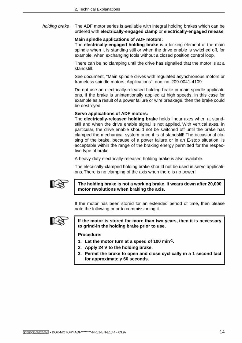
If the motor has been stored for an extended period of time, then pleasenote the following prior to commissioning it.
The holding brake is not a working brake. It wears down after 20,000motor revolutions when braking the axis.
If the motor is stored for more than two years, then it is necessaryto grind-in the holding brake prior to use.
Procedure:
1. Let the motor turn at a speed of 100 min-1.2. Apply 24 V to the holding brake.3. Permit the brake to open and close cyclically in a 1 second tact
for approximately 60 seconds.
• DOK-MOTOR*-ADF********-PRJ1-EN-E1,44 • 03.97 14
2. Technical Explanations
Shaft extension If absolute actual positions are to be derived from the position of the motorshaft, then a shaft extension is needed. This means that an absolute enco-der must be mounted to side B.
The main spindle motor is available, upon request, with a mounted absoluteencoder. (See "AC Main Spindle Drives with Regulated 2AD Main SpindleMotors", doc. no. 9-567-013-4"). A notation on the order next to the absoluteencoder is all that is required.
The shaft extension is a plain shaft. The protection category at delivery is IP65 for the main spindle motor with a shaft extension without mounted enco-der. Encoders must also have protection category IP 65 because there is noseal at the feedthrough of the shaft extension.
Actual incremental position values can be picked off of the motor feedbacksignals of the main spindle drives via the option "incremental encoder out-put". No shaft extension with incremental encoder is needed, in this case.
Balance class The main spindle motor is dynamically balanced as per balance class R(reduced) as per DIN ISO 2373.
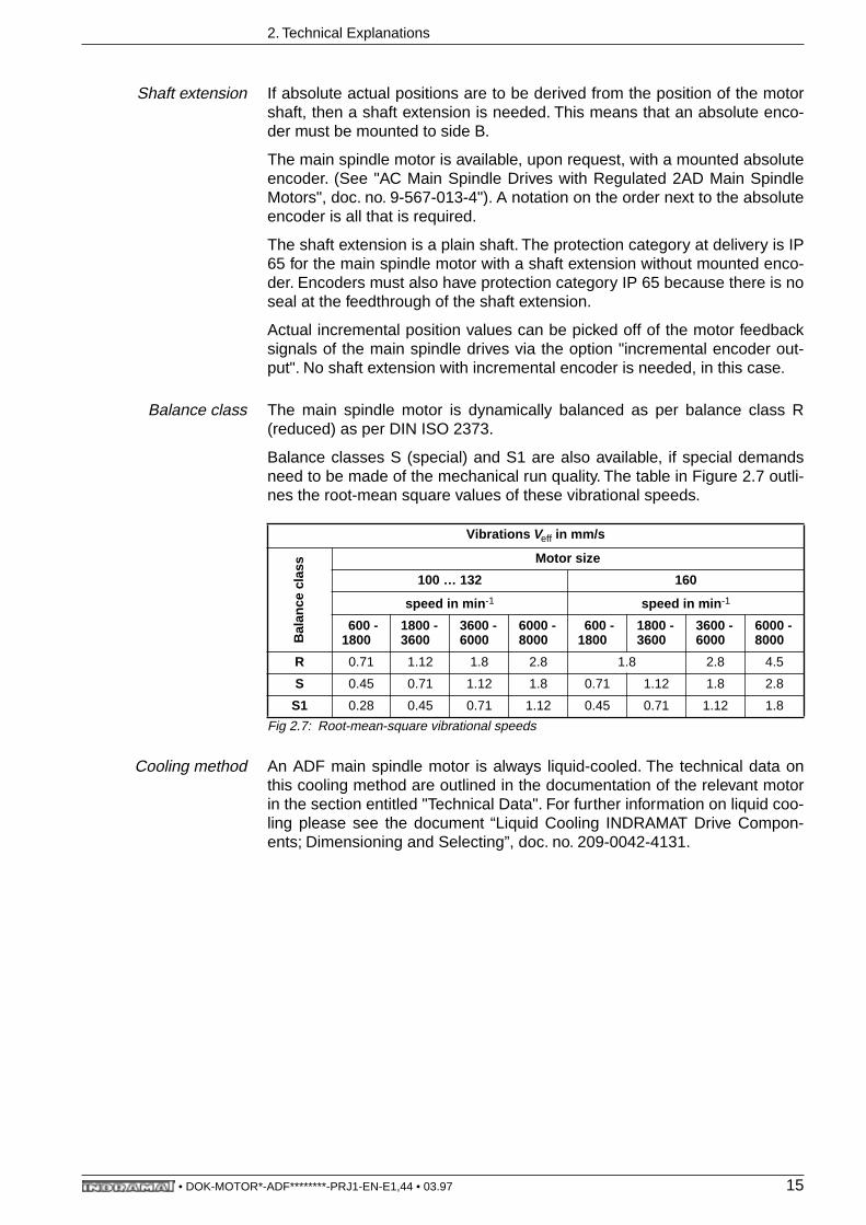
Balance classes S (special) and S1 are also available, if special demandsneed to be made of the mechanical run quality. The table in Figure 2.7 outli-nes the root-mean square values of these vibrational speeds.
Fig 2.7: Root-mean-square vibrational speeds
Cooling method An ADF main spindle motor is always liquid-cooled. The technical data onthis cooling method are outlined in the documentation of the relevant motorin the section entitled "Technical Data". For further information on liquid coo-ling please see the document “Liquid Cooling INDRAMAT Drive Compon-ents; Dimensioning and Selecting”, doc. no. 209-0042-4131.
Vibrations Veff in mm/s
Bal
ance
cla
ss
Motor size
100 … 132 160
speed in min-1 speed in min-1
600 - 1800
1800 - 3600
3600 - 6000
6000 - 8000
600 - 1800
1800 - 3600
3600 - 6000
6000 - 8000
R 0.71 1.12 1.8 2.8 1.8 2.8 4.5
S 0.45 0.71 1.12 1.8 0.71 1.12 1.8 2.8
S1 0.28 0.45 0.71 1.12 0.45 0.71 1.12 1.8
• DOK-MOTOR*-ADF********-PRJ1-EN-E1,44 • 03.97 15
2. Technical Explanations
2.3. Electrical Features
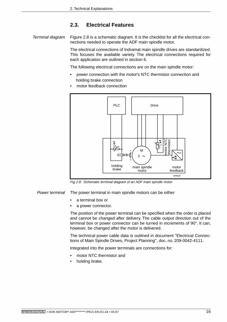
Terminal diagram Figure 2.8 is a schematic diagram. It is the checklist for all the electrical con-nections needed to operate the ADF main spindle motor.
The electrical connections of Indramat main spindle drives are standardized.This focuses the available variety. The electrical connections required foreach application are outlined in section 6.
The following electrical connections are on the main spindle motor:
• power connection with the motor’s NTC thermistor connection and holding brake connection• motor feedback connection
Fig 2.8: Schematic terminal diagram of an ADF main spindle motor
Power terminal The power terminal in main spindle motors can be either
• a terminal box or• a power connector.
The position of the power terminal can be specified when the order is placedand cannot be changed after delivery. The cable output direction out of theterminal box or power connector can be turned in increments of 90°. It can,however, be changed after the motor is delivered.
The technical power cable data is outlined in document "Electrical Connec-tions of Main Spindle Drives, Project Planning", doc. no. 209-0042-4111.
Integrated into the power terminals are connections for:
• motor NTC thermistor and• holding brake.
DrivePLC
M
3
main spindlemotor
motor feedback
holdingbrake
U
mot
or N
TC
ther
mis
tor
APADF
• DOK-MOTOR*-ADF********-PRJ1-EN-E1,44 • 03.97 16

2. Technical Explanations
Motor NTC thermistor The motor NTC thermistor is built into the motor windings. The monitoring ofthe NTC thermistor in the drive protects the motor against overheating. Thedrive sends out an appropriate error message if the motor is shutdown forthermal reasons. (For details see document: "AC Main Spindle Drives withRegulated Asynchronous Motors or Frameless Spindle Motors, Applicati-ons", doc. no. 0041.4109).
holding brake The holding brake connection is integrated into the power terminal. The hol-ding brake is triggered by the unit’s control circuits.
Motor feedback The motor feedback connection is on the same side of the motor as thepower terminal. It is a nine-pin socket. The position of the motor feedbackconnection cannot be changed once the motor is delivered.
• DOK-MOTOR*-ADF********-PRJ1-EN-E1,44 • 03.97 17
3. ADF 100
3. ADF 100
3.1. Technical Data
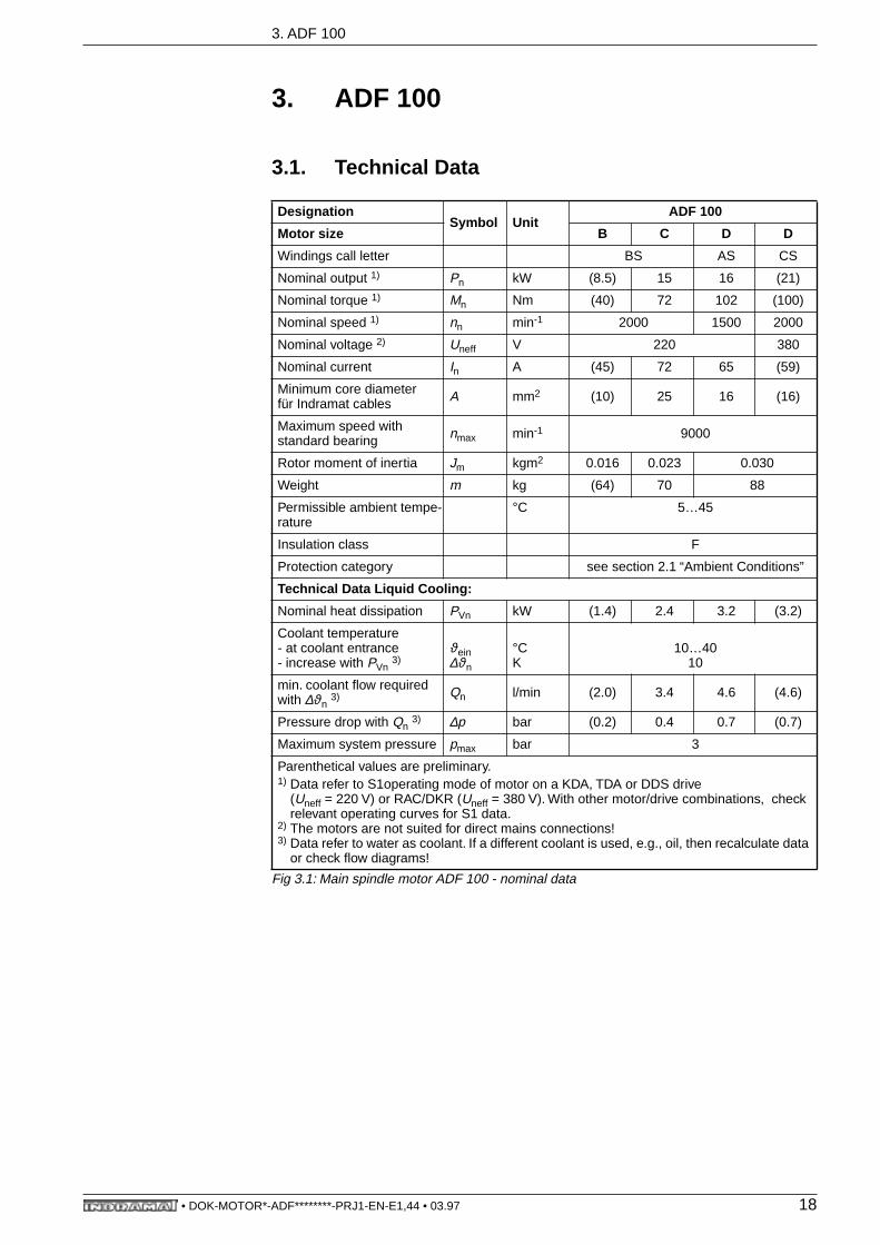
Fig 3.1: Main spindle motor ADF 100 - nominal data
DesignationSymbol Unit
ADF 100
Motor size B C D D
Windings call letter BS AS CS
Nominal output 1) Pn kW (8.5) 15 16 (21)
Nominal torque 1) Mn Nm (40) 72 102 (100)
Nominal speed 1) nn min-1 2000 1500 2000
Nominal voltage 2) Uneff V 220 380
Nominal current In A (45) 72 65 (59)
Minimum core diameter für Indramat cables A mm2 (10) 25 16 (16)
Maximum speed with standard bearing nmax min-1 9000
Rotor moment of inertia Jm kgm2 0.016 0.023 0.030
Weight m kg (64) 70 88
Permissible ambient tempe-rature
°C 5…45
Insulation class F
Protection category see section 2.1 “Ambient Conditions”
Technical Data Liquid Cooling:
Nominal heat dissipation PVn kW (1.4) 2.4 3.2 (3.2)
Coolant temperature - at coolant entrance- increase with PVn 3)
ϑein∆ϑn
°CK
10…4010
min. coolant flow required with ∆ϑn 3) Qn l/min (2.0) 3.4 4.6 (4.6)
Pressure drop with Qn 3) ∆p bar (0.2) 0.4 0.7 (0.7)
Maximum system pressure pmax bar 3
Parenthetical values are preliminary.1) Data refer to S1operating mode of motor on a KDA, TDA or DDS drive
(Uneff = 220 V) or RAC/DKR (Uneff = 380 V). With other motor/drive combinations, check relevant operating curves for S1 data.
2) The motors are not suited for direct mains connections!3) Data refer to water as coolant. If a different coolant is used, e.g., oil, then recalculate data
or check flow diagrams!
• DOK-MOTOR*-ADF********-PRJ1-EN-E1,44 • 03.97 18

3. ADF 100
Permissible shaft load
Fig 3.2: Main spindle motor ADF 100 - permissible shaft load
Lubricant consumptionduration
Fig 3.3: Main spindle motor ADF 100 - lubricant consumption duration
1000
2000
3000
4000
5000
6000
perm
issi
ble
radi
al fo
rce
Fr
in N
nm = 4000 min-1
nm = 8000 min-1
nm = 500 min-1
nm = 1000 min-1
nm = 2000 min-1
DGADF100ZWB
X1
X
Fr
Fa
Fr
Fa
X
X 1
Standard bearing
Load limit for outputshaft with key
1
1
0 10 20 30 40 6050
Distance X in mm
nm
permissible radial force with amechanical lifespan Ln= 20,000working hours
permissible axial force equalling30 N in all mounting orientations
distance between point of application ofthe radial force Fr and the motor flange
permissible area of application ofthe radial force Fr
average speed
5
10
20
6
789
15
25
30x103
0.5 1 2 3 4 65 7 8 9 10 x103
average speed nm in min -1Lubr
icat
ion
cons
umpt
ion
dura
tion
t f in
h
DG2AD100/101FGDStandard bearing1
1
• DOK-MOTOR*-ADF********-PRJ1-EN-E1,44 • 03.97 19

3. ADF 100
3.2. Dimensional Data - ADF 100
Fig 3.4: Main spindle motor ADF 100 - dimensional data
15
m
59,5
35
34
60
ø13
0 j6
ø38
k6
MB ADF100-1
ø18
0
4
1
k135 245
y
2
Detail y
Coolant inlet R 1/8
Coolant outlet R 1/888
46
88
46
53
160
245
45° 45°
ø215
192
13
ADF 100 B ADF 100 C ADF 100 D
405 480 555
386 461 536
Power connection, output direction, can be selected prior to delivery• to side A• to side B• to the right (looking from front towards motor shaft)• to the left
Output shaft, as selected• plain shaft, tolerance as per DIN 42955-R with center hole DS M8x19 as per DIN 332, sh. 2• with key (see dimensions given in options)
Flange dimensions as per DIN 42948
Motor feedback connection
Side B shaft end (see dimensions given in options)
1
2
3
4
5
Main spindle motor, design B05
l
5
Dim.:
k
l
m
291 366 441
55
45°
• DOK-MOTOR*-ADF********-PRJ1-EN-E1,44 • 03.97 20

3. ADF 100
Fig 3.5: Main spindle motor ADF 100 - output shaft with key
Fig 3.6: Main spindle motor ADF 100 - side B shaft end or shaft extension
10N
9
45
60
ø38
k6
5 5+0.2
MB ADF100-3
1 Center hole as per DIN 332 - DS M8
Tolerance: DIN 42955 - R; matching key: DIN 6885 Bl. 1 - A 10 x 8 x 45
1
ø10
h7
9.8
4xM
5 2
1
ø13
4
ø10
2
ø94
H7
2.5
MB ADF100-4
Attachments toside B of the shaft endmust have protectioncategory IP 65 as perDIN 40050.
1 covering cap
2 screw plug
• DOK-MOTOR*-ADF********-PRJ1-EN-E1,44 • 03.97 21
3. ADF 100
3.3. Type Codes
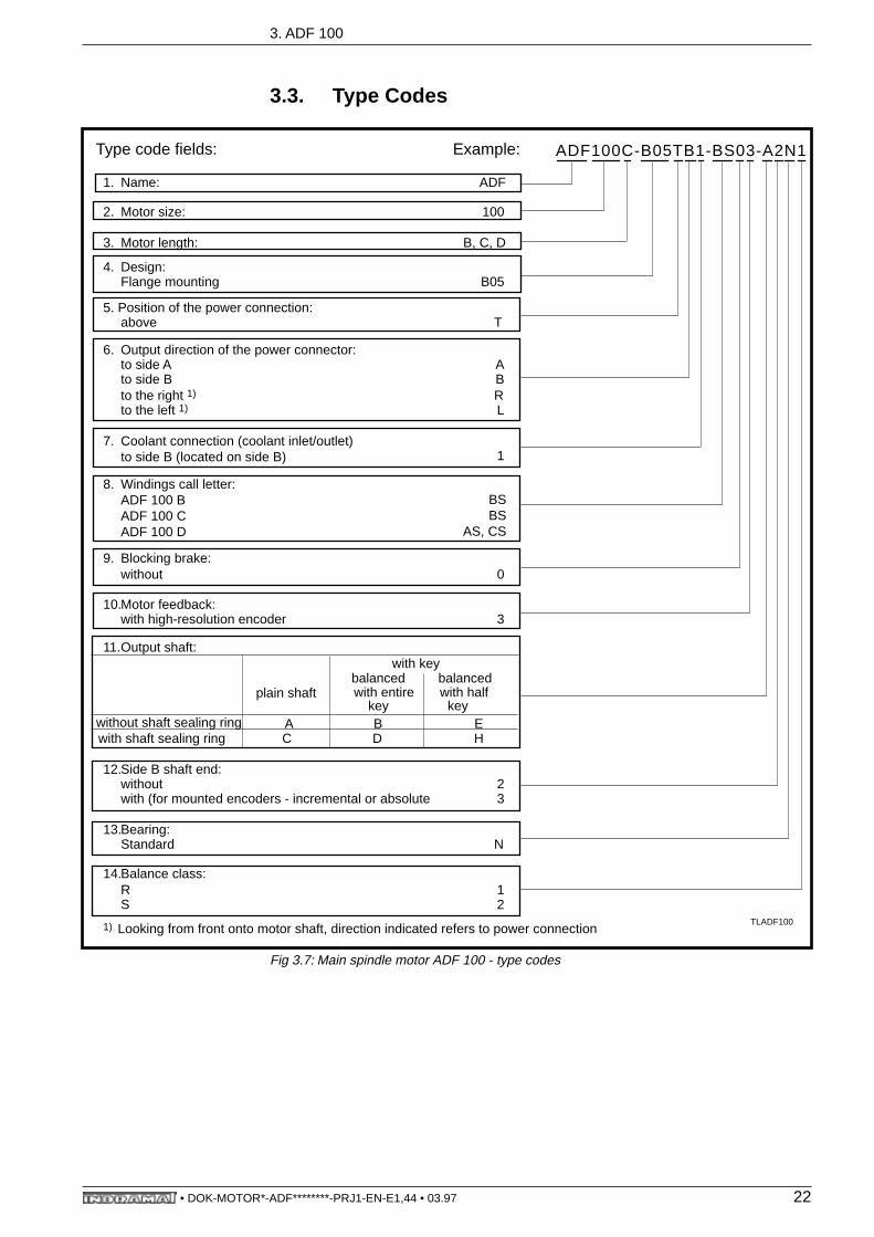
Fig 3.7: Main spindle motor ADF 100 - type codes
1. Name: ADF
2. Motor size: 100
3. Motor length: B, C, D
4. Design:Flange mounting B05
5. Position of the power connection:above T
6. Output direction of the power connector:to side A Ato side B Bto the right 1) Rto the left 1) L
7. Coolant connection (coolant inlet/outlet)to side B (located on side B) 1
8. Windings call letter:ADF 100 BADF 100 CADF 100 D
BSBS
AS, CS
9. Blocking brake:without 0
10.Motor feedback:with high-resolution encoder 3
11.Output shaft: with key
balanced balancedplain shaft with entire with half
key keywithout shaft sealing ring A B Ewith shaft sealing ring C D H
12.Side B shaft end:without 2with (for mounted encoders - incremental or absolute 3
13.Bearing:Standard N
14.Balance class:R 1S 2
1) Looking from front onto motor shaft, direction indicated refers to power connection
Type code fields: Example: ADF100C-B05TB1-BS03-A2N1
TLADF100
• DOK-MOTOR*-ADF********-PRJ1-EN-E1,44 • 03.97 22

4. ADF 132
4. ADF 132
4.1. Technical Data
Fig 4.1: Main spindle motor ADF 132 - nominal data
DesignationSymbol Unit
ADF 132
Motor size B B C C D
Windings call letter DS BS ES BS AS
Nominal output 1) Pn kW 16 (20) 24 33 36
Nominal torque 1) Mn Nm 102 (96) 153 125 229
Nominal speed 1) nn min-1 1500 2000 1500 2500 1500
Nominal voltage 2) Uneff V 380
Nominal current In A 46 (68) 80 89 85
Minimum core diameter für Indramat cables A mm2 10 (16) 25
Maximum speed with - standard bearing- Spindellagerung
nmax min-1 750012000
750012000
750012000
750012000
750010000
Rotor moment of inertia Jm kgm2 0.054 0.076 0.118
Weight m kg 94 (110) (140)
Permissible ambient tem-perature
°C 5…45
Insulation class F
Protection category see section 2.1 “Ambient Conditions”
Technical Data Liquid Cooling:
Nominal heat dissipation PVn kW 2.2 (2.2) 3.0 3.0 4.0
Coolant temperature - at coolant entrance- increase with PVn 3)
ϑein∆ϑn
°CK
10…4010
min. coolant flow required with ∆ϑn 3) Qn l/min 3.2 (3.2) 4.3 4.3 5.7
Pressure drop with Qn 3) ∆p bar 0.1 (0.1) 0.2 0.2 0.3
Maximum system pressure pmax bar 3
Parenthetical values are preliminary.1) Data refer to S1operating mode of motor on a KDA, TDA or DDS drive
(Uneff = 220 V) or RAC/DKR (Uneff = 380 V). With other motor/drive combinations, check relevant operating curves for S1 data
2) The motors are not suited for direct mains connections!3) Data refer to water as coolant. If a different coolant is used, e.g., oil, then recalculate data
or check flow diagrams!
• DOK-MOTOR*-ADF********-PRJ1-EN-E1,44 • 03.97 23

4. ADF 132
Permissible shat load
Fig 4.2: Main spindle motor ADF 132 - permissible shaft load
DGADF132ZWB
X1
X
Fr
Fa
0
1
2
3
4
5
6
0 20 40 60 80 100
Per
mis
sibl
e ra
dial
forc
e F
r in
kN
Load limit for outputshaft with key
2
Fr
Fa
X
X1
nm
Standard bearing
0
1
2
3
4
5
6
0 20 40 60 80 100
Per
mis
ible
rad
ial f
orce
F
r in
kN 2
Heavy-duty bearing
Spindle bearing
0
2
4
6
20 40 60 80 100
8
10
12
14
nm=500 min-1
nm=4000 min-1
nm=2000 min-1
nm=1000 min-1
Per
mis
sibl
e ra
dial
forc
e F
r in
kN
2
1
Load limit for output shaft with plain shaft end
1
nm=500 min-1
nm=1000 min-1
nm=2000 min-1
nm=4000 min-1
nm=8000 min-1
Distance X in mm
Distance X in mm
Distance X in mm
nm=7500 min-1
nm=1000 min-1
nm=2000 min-1nm=4000 min-1nm=8000 min-1nm=12000 min-1
A main spindle motor with heavy-duty bearing may only be operated with a minimum radial force of 1 kN.
permissible radial force with amechanical lifespan Ln= 20,000operating hours
permissible axial force equalling50 N in all mounting orientations
distance between point of application ofthe radial force Fr and the motor flange
permissible area of application ofthe radial force Fr
average speed
• DOK-MOTOR*-ADF********-PRJ1-EN-E1,44 • 03.97 24
4. ADF 132
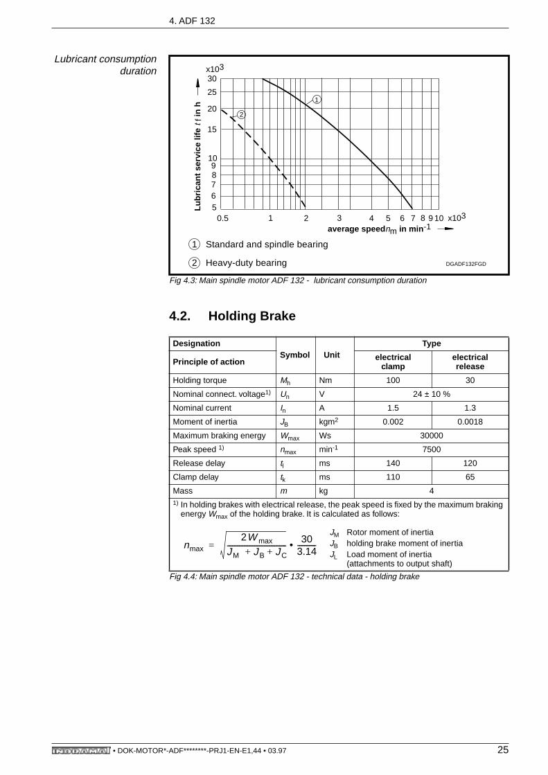
Lubricant consumptionduration
Fig 4.3: Main spindle motor ADF 132 - lubricant consumption duration
4.2. Holding Brake
Fig 4.4: Main spindle motor ADF 132 - technical data - holding brake
DesignationSymbol Unit
Type
Principle of action electricalclamp
electricalrelease
Holding torque Mh Nm 100 30
Nominal connect. voltage1) Un V 24 ± 10 %
Nominal current In A 1.5 1.3
Moment of inertia JB kgm2 0.002 0.0018
Maximum braking energy Wmax Ws 30000
Peak speed 1) nmax min-1 7500
Release delay tl ms 140 120
Clamp delay tk ms 110 65
Mass m kg 41) In holding brakes with electrical release, the peak speed is fixed by the maximum braking
energy Wmax of the holding brake. It is calculated as follows:
JM Rotor moment of inertiaJB holding brake moment of inertiaJL Load moment of inertia
(attachments to output shaft)
DGADF132FGD
Standard and spindle bearing
Heavy-duty bearing
1
2
5
10
20
6789
15
25
30x103
0.5 1 2 3 4 65 7 8 9 10 x103
average speed nm in min -1
Lubr
ican
t ser
vice
life
t f
in h
2
1
nmax2W max
JM JB JC+ +-----------------------------------
303.14-----------•=
• DOK-MOTOR*-ADF********-PRJ1-EN-E1,44 • 03.97 25

4. ADF 132
4.3. Dimensional Data - ADF 132
Fig 4.5: Main spindle motor ADF 132 - dimensional data
MB ADF132-1
87
171
18
ø300
100
45° 45°
260
350
53°
30°
z y
Main spindle motor, high-resolution motor feedback (type 3)
Details y, z
1x45°4
12
1x45°
1x45°
1x45°4
ø11
.5
ø12
.4 -
0.1
Power connection, output direction, selected prior to delivery• to side A• to side B• to the right (looking from front onto motor shaft)• to the left
Output shaft, as selected• plain shaft, tolerance DIN 42955-R with center hole DS M16x36 as per DIN 332 sh. 2• with key (see dimensions under options)
Flange dimensions as per DIN 42948
Motor feedback connection
Side B shaft end (see dimensions under options)
Side B shaft end not possible
Note asymetry when turning terminal box
1
2
3
4
5
6
7
384.5 454.5 584.5
ADF 132 B ADF 132 C ADF 132 DDim.:
a 103 173 303
403.5 473.5 603.5
465.5 535.5 665.5
l 168.5 238.5 268.5
446.5 516.5 646.5
k1 with holdingbrake
w/o holdingbrake
m1 with holdingbrake
w/o holdingbrake
*) *) *)
*) *) *)k2
with holding
w/o holdingbrake
brake
*) *) *)
*) *) *)m2with holding
brake
w/o holdingbrake
*) in preparation
Main spindle motor, digital servo feedback (types 6 and 7)
127,5
ø25
0 h6
5
110 k1
a
ø42
k6
3085.5
186l
m1
1
3
2xPg29
2
57
7
4
k2
m2
4
5
6
*)
• DOK-MOTOR*-ADF********-PRJ1-EN-E1,44 • 03.97 26

4. ADF 132
Fig 4.6: Main spindle motor ADF 132 - output shaft with key
Fig 4.7: Main spindle motor ADF 132 - shaft extension (with high-resolution motor feedback, type 3 only)
MB ADF132-3
1 Center hole DIN 332 - DS M16
Tolerance: DIN 42955 - R; matching key: DIN 6885 Bl. 1 - A 12 x 8 x 80
12N
9
80
110
ø42
k6
15 5+0.2
1
ø10
h7
9.8
4xM
5 2
1
ø12
9
ø10
2
ø94
H7
2.5
MB ADF132-4
Attachments to side B of theshaft end must have protectioncategory IP 65 as per DIN40050.
1 covering cap
2 screw plug
• DOK-MOTOR*-ADF********-PRJ1-EN-E1,44 • 03.97 27
4. ADF 132
4.4. Type Codes
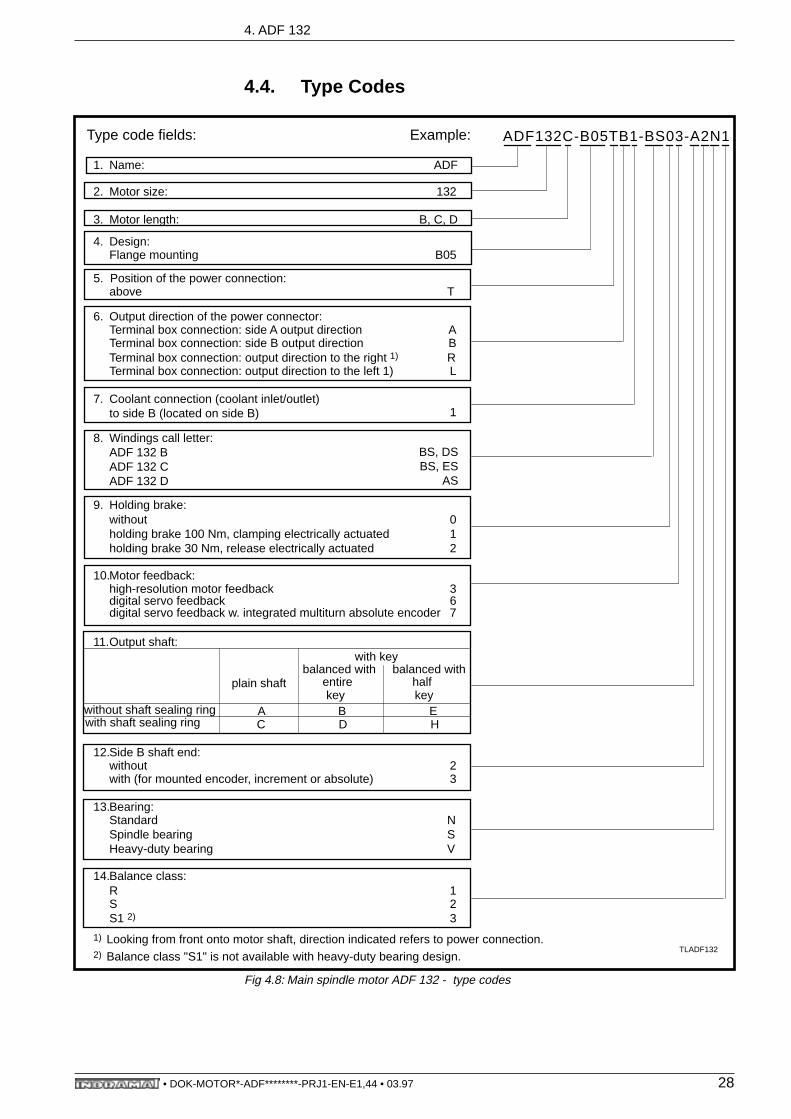
Fig 4.8: Main spindle motor ADF 132 - type codes
1. Name: ADF
2. Motor size: 132
3. Motor length: B, C, D
4. Design:Flange mounting B05
5. Position of the power connection:above T
6. Output direction of the power connector:Terminal box connection: side A output direction ATerminal box connection: side B output direction BTerminal box connection: output direction to the right 1) RTerminal box connection: output direction to the left 1) L
7. Coolant connection (coolant inlet/outlet)to side B (located on side B) 1
8. Windings call letter:ADF 132 BADF 132 CADF 132 D
BS, DSBS, ES
AS
9. Holding brake:withoutholding brake 100 Nm, clamping electrically actuatedholding brake 30 Nm, release electrically actuated
012
10.Motor feedback:high-resolution motor feedbackdigital servo feedbackdigital servo feedback w. integrated multiturn absolute encoder
367
11.Output shaft: with key
balanced with balanced withplain shaft entire half
key keywithout shaft sealing ring A B Ewith shaft sealing ring C D H
12.Side B shaft end:without 2with (for mounted encoder, increment or absolute) 3
13.Bearing:StandardSpindle bearingHeavy-duty bearing
NSV
14.Balance class:R 1SS1 2)
23
1)
2)
Looking from front onto motor shaft, direction indicated refers to power connection.Balance class "S1" is not available with heavy-duty bearing design.
Type code fields: Example: ADF132C-B05TB1-BS03-A2N1
TLADF132
• DOK-MOTOR*-ADF********-PRJ1-EN-E1,44 • 03.97 28
5. ADF 160
5. ADF 160
5.1. Technical Data
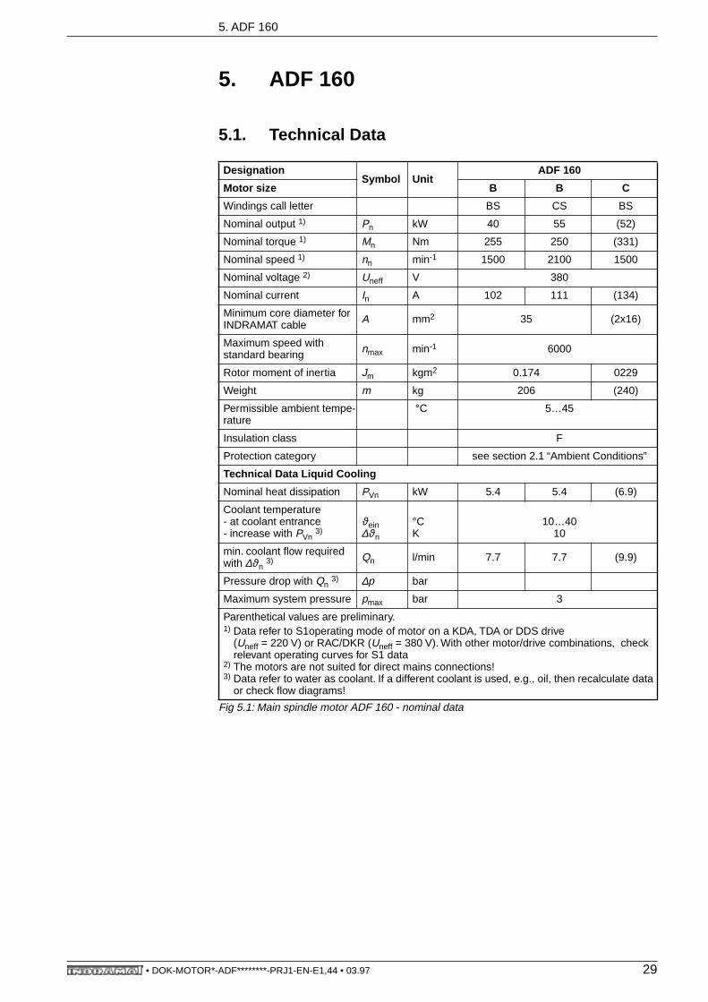
Fig 5.1: Main spindle motor ADF 160 - nominal data
DesignationSymbol Unit
ADF 160
Motor size B B C
Windings call letter BS CS BS
Nominal output 1) Pn kW 40 55 (52)
Nominal torque 1) Mn Nm 255 250 (331)
Nominal speed 1) nn min-1 1500 2100 1500
Nominal voltage 2) Uneff V 380
Nominal current In A 102 111 (134)
Minimum core diameter forINDRAMAT cable A mm2 35 (2x16)
Maximum speed with standard bearing nmax min-1 6000
Rotor moment of inertia Jm kgm2 0.174 0229
Weight m kg 206 (240)
Permissible ambient tempe-rature
°C 5…45
Insulation class F
Protection category see section 2.1 “Ambient Conditions”
Technical Data Liquid Cooling
Nominal heat dissipation PVn kW 5.4 5.4 (6.9)
Coolant temperature - at coolant entrance- increase with PVn 3)
ϑein∆ϑn
°CK
10…4010
min. coolant flow required with ∆ϑn 3) Qn l/min 7.7 7.7 (9.9)
Pressure drop with Qn 3) ∆p bar
Maximum system pressure pmax bar 3
Parenthetical values are preliminary.1) Data refer to S1operating mode of motor on a KDA, TDA or DDS drive
(Uneff = 220 V) or RAC/DKR (Uneff = 380 V). With other motor/drive combinations, check relevant operating curves for S1 data
2) The motors are not suited for direct mains connections!3) Data refer to water as coolant. If a different coolant is used, e.g., oil, then recalculate data
or check flow diagrams!
• DOK-MOTOR*-ADF********-PRJ1-EN-E1,44 • 03.97 29
5. ADF 160
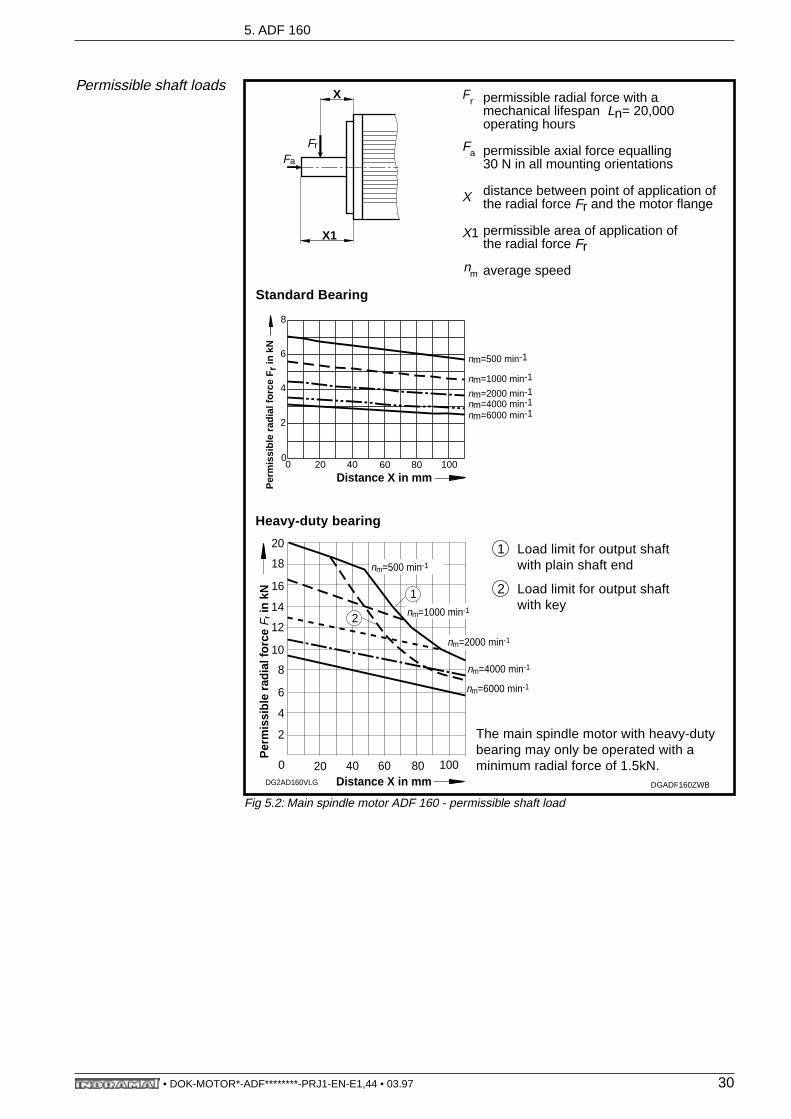
Permissible shaft loads
Fig 5.2: Main spindle motor ADF 160 - permissible shaft load
DGADF160ZWB
X1
X
Fr
Fa
Load limit for output shaftwith key
2
Fr
Fa
X
X1
nm
Standard Bearing
Heavy-duty bearing
Load limit for output shaftwith plain shaft end
1
The main spindle motor with heavy-dutybearing may only be operated with a minimum radial force of 1.5kN.
nm=500 min-1
0
2
4
6
8
0 20 40 60 80 100
Per
mis
sibl
e ra
dial
forc
e F
r in
kN
nm=4000 min-1nm=6000 min-1
nm=1000 min-1
nm=2000 min-1
Distance X in mm0
2
4
6
20 40 60 80 100
8
10
12
14
Per
mis
sibl
e ra
dial
forc
e F r
in k
N 116
18
20
nm=500 min-1
nm=2000 min-1
nm=1000 min-12
nm=4000 min-1
nm=6000 min-1
DG2AD160VLG
Distance X in mm
permissible radial force with amechanical lifespan Ln= 20,000operating hours
permissible axial force equalling30 N in all mounting orientations
distance between point of application ofthe radial force Fr and the motor flange
permissible area of application ofthe radial force Fr
average speed
• DOK-MOTOR*-ADF********-PRJ1-EN-E1,44 • 03.97 30

5. ADF 160
Lubricant consumptionduration
Fig 5.3: Main spindle motor ADF 160 - lubricant consumption duration
5.2. Holding brake
Fig 5.4: Main spindle motor ADF 160 - technical data - holding brake
DesignationSymbol Unit
Type
Principle of action electricalclamp
electrical release
Holding torque Mh Nm 100 70
Nominal connect. voltage1) Un V 24 ± 10 %
Nominal current In A 1.8 2.0
Moment of inertia JB kgm2 0.0065
Maximum braking energy Wmax Ws 40000
Peak speed 1) nmax min-1 6000
Release delay tl ms 120 130
Clamp delay tk ms 90 85
Mass m kg 51) In holding brakes with electrical release, the peak speed is fixed by the maximum braking
energy Wmax of the holding brake. It is calculated as follows:
JM Rotor moment of inertiaJB holding brake moment of inertiaJL Load moment of inertia
(attachments to output shaft)
DGADF160FGD
Standard bearing
Heavy-duty bearing
1
2
x103
1
5
10
20
6
789
15
25
30
0,5 1 2 3 4 65 7 8 9 10 x103
Average speed nm in min -1
Lubr
ican
t ser
vice
t f
in h
2
nmax2W max
JM JB JC+ +-----------------------------------
303.14-----------•=
• DOK-MOTOR*-ADF********-PRJ1-EN-E1,44 • 03.97 31

5. ADF 160
5.3. Dimensional Data - ADF 160
Fig 5.5: Main spindle motor ADF 160 - dimensional data
MB ADF160-1
Main spindle motor, high-resolution motor feedback (type 3)
102
20018
ø350
45° 45°
316
380
53°
z y
Detail y, z
0.5x45°4
12
1x45°
1x45°
1x45°4
ø14
ø15
.2
582 672
ADF 160 B ADF 160 CDim.:
a 269 359
600 690
662 752
l 310 400
644 734
k1 with holdingbrake
w/o holdingbrake
m1with holdingbrake
w/o holdingbrake
*) *)
*) *)k2
with holding
w/o holdingbrake
brake
*) *)
*) *)m2 with holding
brake
w/o holdingbrake
*) in preparation
l
20
ø30
0 h6
ø60
m6
a
k1
m1
110
5
200
138
100
103
2xPg42
1
3
2
4
5
k2
m2
*)
1
2
3
4
5
6
Main spindle motor, digital servo feedback (types 6 and 7)
4
6
Power connection, output direction, selected prior to delivery• to side A• to side B• to the right (looking from front onto motor shaft)• to the left
Output shaft, as selected• plain shaft, tolerance DIN 42955-R with center hole DS M16x36 as per DIN 332 sh. 2• with key (see dimensions under options)
Flange dimensions as per DIN 42948
Motor feedback connection
Side B shaft end (see dimensions under options)
Side B shaft end not possible
• DOK-MOTOR*-ADF********-PRJ1-EN-E1,44 • 03.97 32
5. ADF 160
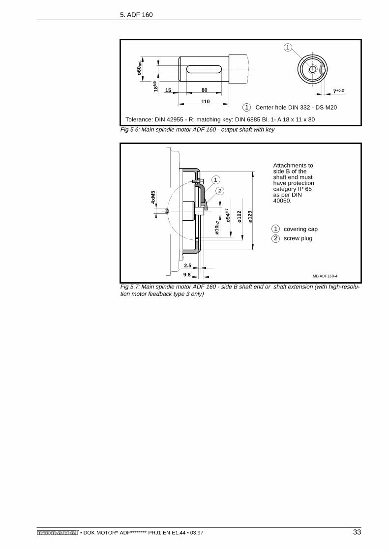
Fig 5.6: Main spindle motor ADF 160 - output shaft with key
Fig 5.7: Main spindle motor ADF 160 - side B shaft end or shaft extension (with high-resolu-tion motor feedback type 3 only)
MB ADF160 3
1 Center hole DIN 332 - DS M20
Tolerance: DIN 42955 - R; matching key: DIN 6885 Bl. 1- A 18 x 11 x 80
18N
9
80
110
ø60
m6
15 7+0.2
1
ø10
h7
9.8
4xM
5 2
1
ø12
9
ø10
2
ø94
H7
2.5
MB ADF160-4
Attachments to side B of the shaft end must have protection category IP 65 as per DIN 40050.
1 covering cap
2 screw plug
• DOK-MOTOR*-ADF********-PRJ1-EN-E1,44 • 03.97 33
5. ADF 160
5.4. Type Codesl
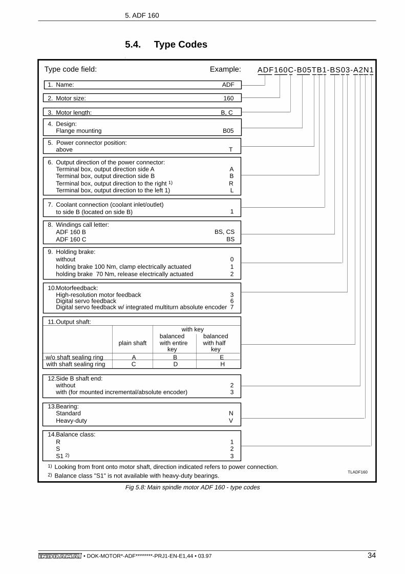
Fig 5.8: Main spindle motor ADF 160 - type codes
1. Name: ADF
2. Motor size: 160
3. Motor length: B, C
4. Design:Flange mounting B05
5. Power connector position:above T
6. Output direction of the power connector:Terminal box, output direction side A ATerminal box, output direction side B BTerminal box, output direction to the right 1) RTerminal box, output direction to the left 1) L
7. Coolant connection (coolant inlet/outlet)to side B (located on side B) 1
8. Windings call letter:ADF 160 BADF 160 C
BS, CSBS
9. Holding brake:withoutholding brake 100 Nm, clamp electrically actuatedholding brake 70 Nm, release electrically actuated
012
10.Motorfeedback:High-resolution motor feedbackDigital servo feedbackDigital servo feedback w/ integrated multiturn absolute encoder
367
11.Output shaft: with key
balanced balancedplain shaft with entire with half
key keyw/o shaft sealing ring A B Ewith shaft sealing ring C D H
12.Side B shaft end:without 2with (for mounted incremental/absolute encoder) 3
13.Bearing:StandardHeavy-duty
NV
14.Balance class:R 1SS1 2)
23
1)
2)
Looking from front onto motor shaft, direction indicated refers to power connection.Balance class "S1" is not available with heavy-duty bearings.
Type code field: Example: ADF160C-B05TB1-BS03-A2N1
TLADF160
• DOK-MOTOR*-ADF********-PRJ1-EN-E1,44 • 03.97 34

6. Electrical Connections
6. Electrical Connections
6.1. Terminal Diagram - ADF 100
Fig 6.1: Terminal diagram - ADF 100 on KDA/TDA
Fig 6.2: Terminal diagram - ADF 100 on DDS02.2
adfstkda
6 0.75 … 1.5 mm2
5 0.75 … 1.5 mm2
GNYE dia. dep. on motor type
1 (see nominal data
2 of motor)
3
DriveKDA / TDA
2
1
3
A1
A2
A3
X8
X12
E
D
A
B
C
H
Jϑ
F
G
ADF100
Motor power connection ADF (power plug-in connector) to KDA/TDA
M
3
ring terminalsfor stud boltsM6
plug-in terminalpart of connectingaccessories kitE • • - • DA
power plug-in connectorCable (coresnumbered as perINDRAMATstandards)
GNYE
shield
7856
12
3
200140ca. 130
50
3030set off length
IN 172/••
(ready-made power cableIKL•••/IKF•••)
adfstdds
6 0.75 … 1.5 mm2
5 0.75 … 1.5 mm2
GNYE dia dep. on motor type
1 (see nominal data
2 of motor)
3
DriveDDS02.2
A1
A2
A3
X5 E
D
A
B
C
H
Jϑ
F
G
ADF100
Motor power connection ADF (power plug-in connection) to DDS
M
3
ring terminals forstud bolt M6 power plug-in connector
Cable(cores numbered perINDRAMATstandards)
GNYE
shield
7856
12
3
200140ca. 130
50
3030set-off length
IN 172/••
(ready-made power cableKL•••/IKF•••)
plug-in terminalis part of connectingacces. kit S 1-...
1TM+
X6
2
3
4
5
TM-
• DOK-MOTOR*-ADF********-PRJ1-EN-E1,44 • 03.97 35

6. Electrical Connections
Fig 6.3: Terminal diagram - ADF 100 on RAC
Fig 6.4: Terminal diagram - ADF 100 on DKR
adfstrac
6 0.75 … 1.5 mm2
5 0.75 … 1.5 mm2
GNYE dia. dep. on motor type
1 (see nominal data of
2 motor)
3
E
D
A
B
C
H
Jϑ
F
G
ADF100
Motor power connection ADF (power plug-in connector) to RAC
M
3
plug-in terminalpart of electricalconnecting kitE • • - • DA
power plug-in connectorCable(cores numbered perINDRAMATstandards)
shield
7856
200ca. 130
50
set-off length
IN 172/••
(ready-made power cableIKL•••/IKF•••)
ferrules orring terminals
DriveRAC
2
3
1
A1
A2
A3
X14
X16
GNYE12
200
3
adfstdkr
6 0.75 … 1.5 mm2
5 0.75 … 1.5 mm2
GNYE dia. dep. on motor type
1 (see nominal data
2 of motor)
3
E
D
A
B
C
H
Jϑ
F
G
ADF100
Motor power connection ADF (power plug-in connector) to DKR
M
3
power plug-in connectorcable(cores numberedper INDRAMATstandards)
shield
7856
200ca. 130
50
set-offlength
IN 172/••
(ready-made power cableIKL•••/IKF•••)
ferrules or ringterminals
DriveDKR
A1
A2
A3
X5
GNYE12
200
3
plug-in terminalpart of connectoraccessories kitS 1-DKS 1
1TM+
X6
2
3
4
5
TM-
• DOK-MOTOR*-ADF********-PRJ1-EN-E1,44 • 03.97 36
6. Electrical Connections
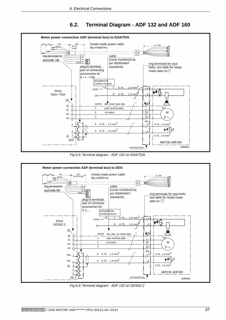
6.2. Terminal Diagram - ADF 132 and ADF 160
Fig 6.5: Terminal diagram - ADF 132 on KDA/TDA
Fig 6.6: Terminal diagram - ADF 132 on DDS02.2
Motor power connection ADF (terminal box) to KDA/TDA
cable(cores numbered asper INDRAMATstandards)
shield
7856
200ca. 150set-off
length
(ready-made power cableIKL•••/IKF•••)
6 0.75 … 1.5 mm2
5 0.75 … 1.5 mm2
GNYE dia. motor type dep.
1 (see nominal data
2 of motor)
3
ϑ
ADF132, ADF160
M
3
adfklkda
0.75...1.5 mm2
0.75...1.5 mm2
terminal box
DriveKDA / TDA
2
1
3
A1
A2
A3
X8
X12
ring terminals forstud bolts M6
GNYE1
23
1403030
plug-in terminalpart of connectingaccessories kitE • • - • DA
ring terminals for studbolts, see table for ready-made data on
U1
V1
W13
4
7 0.75 … 1.5 mm2
8 0.75 … 1.5 mm2
1
20V
+24V
actuated bycontrol circuits
Motor power connection ADF (terminal box) to DDS
cable(cores numbered asper INDRAMATstandards)
shield
7856
200ca. 150set-off length
(ready-made power cableIKL•••/IKF•••)
6 0.75 … 1.5 mm2
5 0.75 … 1.5 mm2
GNYE dia. dep. on motor type
1 (see nominal data
2 of motor)
3
ϑ
ADF132, ADF160
M
3
adfkldds
0.75...1.5 mm2
0.75...1.5 mm2
terminal box
DriveDDS02.2
A1
A2
A3
X5
ring terminal forstud bolts M6
GNYE1
23
1403030
ring terminals for stud boltssee table for ready-madedata on
U1
V1
W1
plug-in terminalspart of connectoraccessories kitS 1-...
1TM+
X6
2
3
4
5
TM-
7 0.75 … 1.5 mm2
8 0.75 … 1.5 mm2
1
20V
+24V
actuated bycontrol circuit
3
4
• DOK-MOTOR*-ADF********-PRJ1-EN-E1,44 • 03.97 37
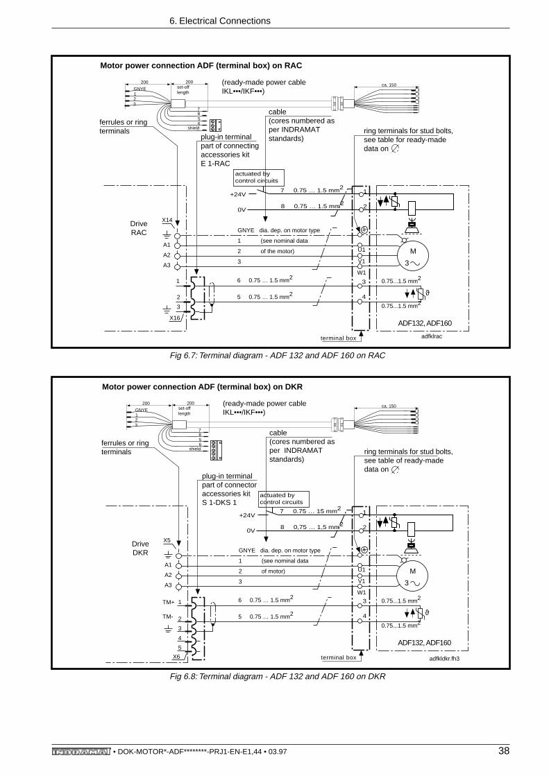
6. Electrical Connections
Fig 6.7: Terminal diagram - ADF 132 and ADF 160 on RAC
Fig 6.8: Terminal diagram - ADF 132 and ADF 160 on DKR
Motor power connection ADF (terminal box) on RAC
plug-in terminalpart of connectingaccessories kitE 1-RAC
cable(cores numbered asper INDRAMATstandards)
shield
7856
200ca. 150set-off
length
(ready-made power cableIKL•••/IKF•••)
6 0.75 … 1.5 mm2
5 0.75 … 1.5 mm2
GNYE dia. dep. on motor type
1 (see nominal data
2 of the motor)
3
ϑ
ADF132, ADF160
M
3
adfklrac
0.75...1.5 mm2
0.75...1.5 mm2
terminal box
ferrules or ringterminals
DriveRAC
2
3
1
A1
A2
A3
X14
X16
GNYE12
200
3
ring terminals for stud bolts,see table for ready-madedata on
U1
V1
W1
7 0.75 … 1.5 mm2
8 0.75 … 1.5 mm2
1
20V
+24V
actuated bycontrol circuits
3
4
Motor power connection ADF (terminal box) on DKR
plug-in terminalpart of connectoraccessories kitS 1-DKS 1
cable(cores numbered asper INDRAMATstandards)
shield
7856
200ca. 150set-off
length
(ready-made power cableIKL•••/IKF•••)
6 0.75 … 1.5 mm2
5 0.75 … 1.5 mm2
GNYE dia. dep. on motor type
1 (see nominal data
2 of motor)
3
ϑ
ADF132, ADF160
M
3
adfkldkr.fh3
0.75...1.5 mm2
0.75...1.5 mm2
terminal box
ferrules or ringterminals
DriveDKR
A1
A2
A3
X5
GNYE12
200
3
ring terminals for stud bolts,see table of ready-madedata on
U1
V1
W1
1TM+
X6
2
3
4
5
TM-
7 0.75 … 15 mm2
8 0,75 … 1,5 mm2
1
20V
+24V
actuated bycontrol circuits
3
4
• DOK-MOTOR*-ADF********-PRJ1-EN-E1,44 • 03.97 38
6. Electrical Connections
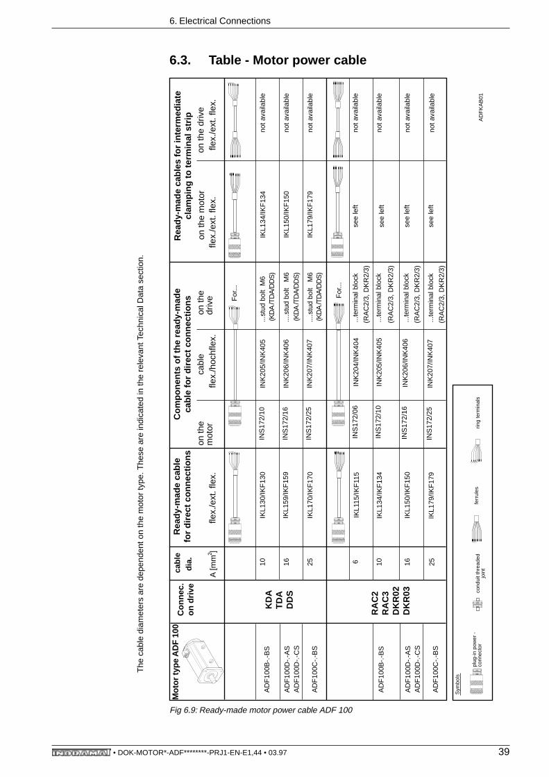
6.3. Table - Motor power cable
Fig 6.9: Ready-made motor power cable ADF 100
cabl
eR
eady
-mad
e ca
ble
for
dire
ct c
onne
ctio
nsC
ompo
nent
s of
the
read
y-m
ade
cabl
e fo
r di
rect
con
nect
ions
Rea
dy-m
ade
cabl
es fo
r in
term
edia
tecl
ampi
ng to
term
inal
str
ipdi
a.
on th
em
otor
cabl
eon
the
driv
eon
the
driv
eA
[mm
]fle
x./h
ochf
lex.
flex.
/ext
. fle
x.fle
x./e
xt. f
lex.
10IK
L130
/IKF
130
...st
ud b
olt
M6
IKL1
34/IK
F13
4no
t ava
ilabl
e
16...
.stu
d bo
lt M
6IK
L150
/IKF
150
not a
vaila
ble
25IK
L170
/IKF
170
....s
tud
bolt
M6
not a
vaila
ble
6IK
L115
/IKF
115
...te
rmin
al b
lock
see
left
not a
vaila
ble
(RA
C2/
3, D
KR
2/3)
10IK
L134
/IKF
134
not a
vaila
ble
16IK
L150
/IKF
150
not a
vaila
ble
For
...
For
...
...te
rmin
al b
lock
...te
rmin
al b
lock
flex.
/ext
. fle
x.
AD
FK
AB
01
2
(KD
A /T
DA
/DD
S)
(KD
A /T
DA
/DD
S)
(KD
A /T
DA
/DD
S)
(RA
C2/
3, D
KR
2/3)
(RA
C2/
3, D
KR
2/3)
25no
t ava
ilabl
e...
term
inal
blo
ck
(RA
C2/
3, D
KR
2/3)
INS
172/
10IN
K20
5/IN
K40
5
INS
172/
16IN
K20
6/IN
K40
6
INS
172/
25IN
K20
7/IN
K40
7
INS
172/
06IN
K20
4/IN
K40
4
INS
172/
10IN
K20
5/IN
K40
5
INS
172/
16IN
K20
6/IN
K40
6
INS
172/
25IN
K20
7/IN
K40
7
IKL1
59/IK
F15
9
IKL1
79/IK
F17
9
see
left
see
left
see
left
IKL1
79/IK
F17
9
KD
AT
DA
DD
S
The
cab
le d
iam
eter
s ar
e de
pend
ent o
n th
e m
otor
type
. The
se a
re in
dica
ted
in th
e re
leva
nt T
echn
ical
Dat
a se
ctio
n.
Con
nec.
on d
rive
RA
C2
RA
C3
DK
R02
DK
R03
Mot
or ty
pe A
DF
100
AD
F10
0B-.
-BS
AD
F10
0D-.
-AS
AD
F10
0D-.
-CS
AD
F10
0C-.
-BS
AD
F10
0B-.
-BS
AD
F10
0D-.
-AS
AD
F10
0D-.
-CS
AD
F10
0C-.
-BS
plug
-in p
ower
-co
nnec
tor
Sym
bols
ferr
ules
ring
term
inal
sco
ndui
t thr
eade
djo
int
on th
e m
otor
• DOK-MOTOR*-ADF********-PRJ1-EN-E1,44 • 03.97 39

6. Electrical Connections
Fig 6.10: Ready-made motor power cables ADF 132 and ADF 160
Cab
leR
eady
-mad
e ca
ble
for
dire
ct c
onne
ctio
nsC
ompo
nent
s of
the
read
y-m
ade
cabl
e fo
r di
rect
con
nect
ions
Rea
dy-m
ade
cabl
es fo
r in
term
edia
tecl
ampi
ng to
term
inal
str
ipdi
a-
met
eron
the
mot
orca
ble
on d
rive
on th
e m
ot.
on th
e dr
ive
A [m
m ]
flex.
/ext
. fle
x.fle
x./e
xt. f
lex.
flex.
/ext
. fle
x.
IKL1
36/IK
F13
6se
e le
ft
IKL1
51/IK
F15
1
IKL1
72/IK
F17
2
IKL1
82/
*)
50IK
L 19
1/ *
)IN
K26
8/ *
)...
scre
w M
12*)
(RA
C4,
DK
R4)
25IN
K20
7/IN
K40
7
(PG
29)
(PG
29)
10 16 25 35
AD
FK
AB
02.F
H3
IKL
175/
IKF
175
(PG
42)
(PG
36)
For
...
...te
rmin
al b
lock
....te
rmin
al b
lock
....te
rmin
al b
lock
....te
rmin
al b
lock
..stu
d M
6 M8
..stu
d M
8 M8
..stu
d M
8 M8
..stu
d M
10 M10
*)
..stu
d M
10 M10
.. st
ud M
12 M12
INK
267
10IK
L135
/IKF
135
INK
205/
INK
405
..stu
d M
6IK
L136
/IKF
136
no
ta
vail.
(PG
29)
(KD
A/T
DA
/DD
S)
16IK
L157
/IKF
157
..stu
d M
6IK
L151
/IKF
151
(PG
29)
25IK
L174
/IKF
174
..stu
d M
6IK
L172
/IKF
172
(PG
29)
Für
... F
or...
..stu
d M
6 M8
..stu
d. M
6 M8
.stu
d M
8 M8
2
For
...
no
ta
vail.
no
ta
vail.
no
ta
vail.
no
ta
vail.
nno
ta
vail.
no
ta
vail.
not
ava
il.
no
ta
vail.
*) A
vaila
ble,
req
uest
type
cod
e fr
om
IND
RA
MA
T, D
ept.
EN
T
For
... F
or...
(KD
A/T
DA
/DD
S)
(KD
A/T
DA
/DD
S)
(RA
C2/
3, D
KR
2/3)
(RA
C2/
3, D
KR
2/3)
(RA
C2/
3, D
KR
2/3)
(RA
C2/
3, D
KR
2/3)
...sc
rew
M12
(RA
C4,
DK
R4)
(PG
42)
(PG
48)
INK
206/
INK
406
INK
207/
INK
407
INK
205/
INK
405
INK
206/
INK
406
INK
207/
INK
407
see
left
see
left
see
left
The
cab
le d
iam
eter
s ar
e de
pend
ent o
n th
e m
otor
type
. The
se a
re in
dica
ted
in th
e re
leva
nt T
echn
ical
Dat
a se
ctio
n.
35IN
K26
7/*)
*)n
ot
ava
il.
...sc
rew
M12
(RA
C4,
DK
R4)
KD
AT
DA
DD
S
Con
nec.
todr
ive
RA
C2
RA
C3
DK
R02
DK
R03
Mot
or ty
pe A
DF
132/
160
AD
F13
2B-.
-DS
RA
C4
DK
R04
AD
F13
2B-.
-BS
AD
F13
2C-.
-ES
AD
F13
2C-.
-BS
AD
F13
2D-.
-AS
AD
F13
2B-.
-DS
AD
F13
2B-.
-BS
AD
F13
2C-.
-ES
AD
F13
2C-.
-BS
AD
F13
2D-.
-AS
AD
F16
0B-.
-BS
AD
F16
0B-.
-CS
2x16
....te
rmin
al b
lock
no
ta
vail.
(RA
C2/
3, D
KR
2/3)
INK
206/
INK
406
see
left
AD
F16
0C-.
-BS
*)..s
tud
M10 M
10
IKL
183/
*)
..stu
d M
12 M12
(PG
48)
Sym
bols
:
ferr
ules
ring
term
inal
sco
ndui
t thr
eade
djo
int (
PG
)
flex.
/ext
. fle
x.
• DOK-MOTOR*-ADF********-PRJ1-EN-E1,44 • 03.97 40

6. Electrical Connections
6.4. Terminal Diagram - Motor Feedback
Fig 6.11: Terminal diagram - high-resolution motor feedback on KDA, TDA, RAC
0
SBDSUB7
X3
Cable INK 209(color coded as perINDRAMAT standards)
D-Sub plug-in conn. (15-pin)INS 439
Drives ...KDA, TDA, RAC
2
11
13
14
15
PK
GY
BN
GN
0.25 mm2
0.25 mm2
0.25 mm2
0.25 mm2
0ref
B
Bref
Aref
A7
9
12
10
+ 5Vint
0Vint
1
2
3
4
5
6
9
7
8
motor feedbackhigh-resolution(insulated sensor mounting)
VT
BU
0.25 mm2
0.25 mm2
WH
BN
1 mm2
1 mm2
Plug-in conn. (9-pin)INS 401
Ready-made cable IKS032/...
Ready-made cableIKS 315/..
52
26
61
4745
Plug-in conn. (9-pin)INS 309
45
Do not conduct the cable to the high-resolution motor feedbackover a terminal strip as it is highly susceptible to interference!
• DOK-MOTOR*-ADF********-PRJ1-EN-E1,44 • 03.97 41

6. Electrical Connections
Fig 6.12: Terminal diagram - high resolution motor feedback on DDS02.2, DKR
0
FDBDZF21
X50, DZF2.1M
Cable INK 209(color coded as perINDRAMAT standards)
D-Sub connector (15-pin)INS 519
Drive ..DDS02.2, DKR
2
11
13
14
15
PK
GY
BN
GN
0.25 mm2
0.25 mm2
0.25 mm2
0.25 mm2
0ref
B
Bref
Aref
A7
9
12
10
+ 5Vint
0Vint
1
2
3
4
5
6
9
7
8
Motor feedbackhigh-resolution(insulated sensor mounting)
VT
BU
0.25 mm2
0.25 mm2
WH
BN
1 mm2
1 mm2
Plug-in conn. (9-pin)INS 401
Ready-made cableIKS 315/..
52
26
61
4745
Plug-in conn. (9-pin)INS 309
Do not conduct the cable to the high-resolution motor feedbackover a terminal strip as it is highly susceptible to interference!
• DOK-MOTOR*-ADF********-PRJ1-EN-E1,44 • 03.97 42
6. Electrical Connections
6.5. Type Designations
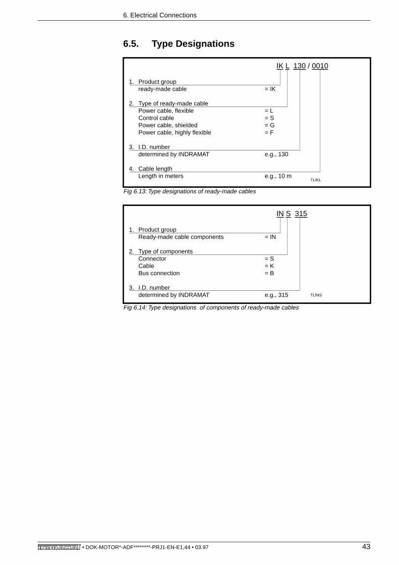
Fig 6.13: Type designations of ready-made cables
Fig 6.14: Type designations of components of ready-made cables
1. Product groupready-made cable = IK
2. Type of ready-made cablePower cable, flexible = LControl cable = SPower cable, shielded = G
Power cable, highly flexible = F
3. I.D. numberdetermined by INDRAMAT e.g., 130
4. Cable lengthLength in meters e.g., 10 m
IK L 130 / 0010
TLIKL
1. Product groupReady-made cable components = IN
2. Type of componentsConnector = SCable = KBus connection = B
3. I.D. numberdetermined by INDRAMAT e.g., 315
IN S 315
TLINS
• DOK-MOTOR*-ADF********-PRJ1-EN-E1,44 • 03.97 43

7. Condition at Delivery
7. Condition at DeliveryThe motor is packed onto a pallet or in cartons (depending on the number ofor the size of the motors).
If a single motor is packed on a pallet, then it is secured by heavy-dutysquare timbered corners to prevent shifting and lashed with taut metalbands onto the pallet. If several motors are delivered at the same time, thenup to three motors can be lashed onto one pallet. Styroform or cartons pre-vent them from colliding or impacting.
A carton is pulled over the items and fixed firmly into place with taut bands toprotect them against inclement weather.
The items can be unpacked without damaging them by simply cuttingthrough the bands.
Warning
There is an envelope with delivery slip attached to the carton. There is alsoa barcode sticker on the packaging.
Caution! There is considerable tension in the taut band!
There is the danger of injury from the uncontrolled movements ofthe taut bands when these are cut through!
Maintain a sufficient safety distance! Remove taut bands carefully!
• DOK-MOTOR*-ADF********-PRJ1-EN-E1,44 • 03.97 44
8. Identifying the Merchandise
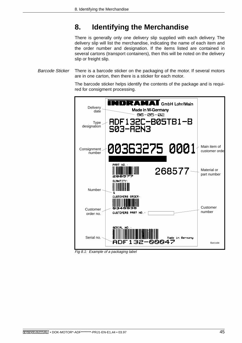
8. Identifying the MerchandiseThere is generally only one delivery slip supplied with each delivery. Thedelivery slip will list the merchandise, indicating the name of each item andthe order number and designation. If the items listed are contained inseveral cartons (transport containers), then this will be noted on the deliveryslip or freight slip.
Barcode Sticker There is a barcode sticker on the packaging of the motor. If several motorsare in one carton, then there is a sticker for each motor.
The barcode sticker helps identify the contents of the package and is requi-red for consigment processing.
Fig 8.1: Example of a packaging label
Barcode
Delivery date
Typedesignation
Consignmentnumber
Number
Customerorder no.
Serial no.
Main item ofcustomer order
Material orpart number
Customernumber
• DOK-MOTOR*-ADF********-PRJ1-EN-E1,44 • 03.97 45
8. Identifying the Merchandise
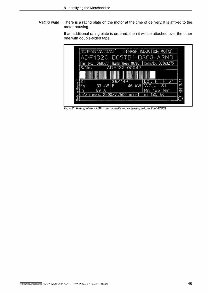
Rating plate There is a rating plate on the motor at the time of delivery. It is affixed to themotor housing.
If an additional rating plate is ordered, then it will be attached over the otherone with double-sided tape.
Fig 8.2: Rating plate - ADF main spindle motor (example) per DIN 42961
• DOK-MOTOR*-ADF********-PRJ1-EN-E1,44 • 03.97 46
9. Storage, Transportation and Handling
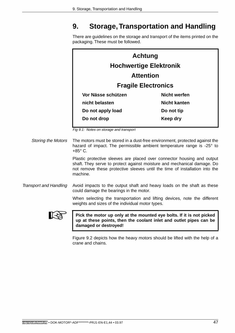
9. Storage, Transportation and HandlingThere are guidelines on the storage and transport of the items printed on thepackaging. These must be followed.
Fig 9.1: Notes on storage and transport
Storing the Motors The motors must be stored in a dust-free environment, protected against thehazard of impact. The permissible ambient temperature range is -25° to+85° C.
Plastic protective sleeves are placed over connector housing and outputshaft. They serve to protect against moisture and mechanical damage. Donot remove these protective sleeves until the time of installation into themachine.
Transport and Handling Avoid impacts to the output shaft and heavy loads on the shaft as thesecould damage the bearings in the motor.
When selecting the transportation and lifting devices, note the differentweights and sizes of the individual motor types.
Figure 9.2 depicts how the heavy motors should be lifted with the help of acrane and chains.
Achtung
Hochwertige Elektronik
Attention
Fragile ElectronicsVor Nässe schützen Nicht werfen
nicht belasten Nicht kanten
Do not apply load Do not tip
Do not drop Keep dry
Pick the motor up only at the mounted eye bolts. If it is not pickedup at these points, then the coolant inlet and outlet pipes can bedamaged or destroyed!
• DOK-MOTOR*-ADF********-PRJ1-EN-E1,44 • 03.97 47

9. Storage, Transportation and Handling
Fig 9.2: Lifting and transporting an ADF main spindle motor using appropriate chain equip-ment
FAKETTEHEBEN
• DOK-MOTOR*-ADF********-PRJ1-EN-E1,44 • 03.97 48
10. Mounting and Installation Guidelines
10. Mounting and Installation Guidelines The following guidelines should be complied with to avoid damaging themotor during commissioning and mounting.
• The larger and thus heavier motors may only be lifted and transportedwith the use of appropriate tools and devices as per section 11.
• Avoid shocks or impacts to the output shaft or impact stress to the shaft,as these may damage the bearing assembly of the motor.
• The motors may only be assembled and installed by properly trained per-sonnel.
• The screwed caps on the connectors (motor power connector and feed-back connector) must be screwed tightly into place when mounting.
• Ground the motor to the drive.• Follow manufacturer’s circuit diagrams when wiring the motor! • The motor and the machine/facility may only be commissioned by trained
personnel and under the supervision of an electrician.
• DOK-MOTOR*-ADF********-PRJ1-EN-E1,44 • 03.97 49

11. Commissioning
11. CommissioningThe commissioning process is the same for all main spindle motors. It isdescribed in Indramat’s main spindle motor documentation entitled, "ACMain Spindle Drives with Regulated Asynchronous Motors or FramelessSpindle Motors, Applications", doc. no. 209-0041-4109!
• DOK-MOTOR*-ADF********-PRJ1-EN-E1,44 • 03.97 50
12. Service Guidelines
12. Service Guidelines
12.1. Contacting Customer Service
INDRAMAT customer service can be reached at the following hotline phonenumbers at the times indicated.
Service-Hotline Phone no. 0172-6600406 or 0171-3338826
Monday - Friday 7.00 a.m. to 11.00 p.m.Saturday 8.00 a.m. to 8 p.m.Sundays and holidays 9.00 a.m. to 7 p.m.
Please note the following information prior to contact Indramat CustomerService.
• Type data of the drive and motor • the faulty• any and all fault or diagnostics displays.
This will help to rapidly and carefully locate the problem and eliminate it.
If a motor is returned, then please copy the repair card on the following pageand return this, after it has been carefully filled out, with the motor. This willassist in locating the fault caused by this particular application.
• DOK-MOTOR*-ADF********-PRJ1-EN-E1,44 • 03.97 51

12. Service Guidelines
12.2. Repair Report Card
Fig 12.1: Repair report card
PlRepBegl
Repair Report Cardfor INDRAMAT equipment and components
Name: Co./Loc.: Date:
Part no. (by replacementof parts)
SN:
Del. cons. no.:
Deliv. date:
Mach. manuf./co.: Type:
A x i s : horizontalvertical
Mach. no.:
Op. time:
Commissionig date (if applic.):
Date failed:
Fault status:
Fault
always presentoccurs sporadicallyoccurs after ca. ___ hrs.occurs with vibrationstemperature dependentother
Failure cause:
unknownconnection errorext. shortmech. damageloose cable conn,other
Additional notes: (e.g., LED diagnostics, error message in display)
General info:
no functioningruns erraticallyuncontrolled drive movementsfault in only one directionsupply fuse trippedother
Supplementary Notes
Concomitant phenomenon:
Problems in mech. sys.Power section failedControl failedMotor failed Cable breakother
SN:
Drive, Supply Unit, Drive, Power Section:
Control voltage faultyPower sec. fuse F ___ failedDefective blowerDefective bleeder resistorFaulty power voltageConn. bolt torn offOther
Control: Motor: Comments:
no functioningno displayso setpoint outputDiagnosisdim. offset in ___ directioninterrupt in E-stop loopposition control loop won't closeerror in program sequencyint. aux. function fault(outputs)acknowledements not accepted (inputs)other
Thermoelement defectBrake defectBlower defectFeedback defectTachosignal faultyBLC signal faultyShort to groundThermal overloadother
• DOK-MOTOR*-ADF********-PRJ1-EN-E1,44 • 03.97 52
13. Index
13. Index
AAbsolute encoder 15ADF protection categories 9Ambient temperature 8
BBalance class 15Barcode sticker 45Barcode-Aufkleber 45Bearing service life 12
CContact and penetration by foreign objects 9Cooling method 15
EElektrische Verbindung 35
HHolding brake 14, 17Housing paint 10
IIdentifikation der Ware 45Incremental encoder output 15Installation position 11Installaton elevation 8
KKey 11
LLagerlebensdauer 12Liquid cooling 15Lubrication Consumption Duration 13
MMechanical ambient conditions 10Motor feedback 5Motor feedback connection 17Motor NTC thermistor 17Mounted encoder 15Mounting and Installation Guidelines 49Mounting flange 11
NNormal loads 12
OOutput shaft 11Output shaft with seal 12
PPermissible shaft load 12
• DOK-MOTOR*-ADF********-PRJ1-EN-E1,44 • 03.97 53

13. Index
Power range 5Power terminal 16Protection against water 9Protection category 8
RRating plate 46Repair Report Card 52
SService-Hotline 51Shaft extension 15Storage, Transportation and Handling 47
TTerminal box 16Terminal Diagram 35, 37, 41Terminal diagram 16Type of construction 11
• DOK-MOTOR*-ADF********-PRJ1-EN-E1,44 • 03.97 54

Bosch Rexroth AGElectric Drives and ControlsP.O. Box 13 5797803 Lohr, GermanyBgm.-Dr.-Nebel-Str. 297816 Lohr, GermanyPhone +49 (0)93 52-40-50 60Fax +49 (0)93 52-40-49 [email protected]
Printed in GermanyDOK-MOTOR*-ADF********-PRJ1-EN-PR911271431
Top Related