


Languages
Pages
Legal


Retrofits / Upgrades of
Gas Turbine Exhaust Ducts
Major Drivers ofRetrofits / upgrades of Gas Turbine Exhaust Ducts
• Change in Power Plant Operation
– Due to changes in operating regimes (two shifting etc.) many gas-fired power plants are now facing a significant amount of repetitive maintenance on Gas Turbine Exhaust ducts during their annual outages.
– Damage mechanisms are often related to the increased number of unit starts and high flue gas velocities in the GT exhaust ducting.
– Minor defects in the external / internal insulation of exhaust ducts system can rapidly lead to widespread damage (potential for significant loss of plant availability).
• Upgrading duct systems of ageing Power Plants
– Many of the “older” power stations can be upgraded from a “hot casing” design to a “cold casing” design extending Power Plant Life and reducing maintenance cost.
– “Noise reduction requirements include the installation of additional Silencer splitters
General Capabilities• GE Frame Engine Exhausts
– Frame 3,5,7,9 (Both E,F as H types)
• ALSTOM GT Exhausts– GT8, GT10, GT11, GT13, GT24, GT26
• MITSUBISHI GT Exhausts– 501, 701 (Both D as F Types)
• Siemens GT Exhausts– V64, V94 (Both type 1,2 as well as 3)
• Others– LM engine exhausts, Aeroderivative Exhausts
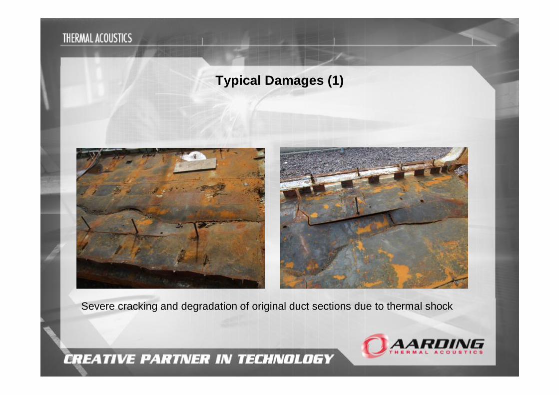
Typical Damages (1)
Severe cracking and degradation of original duct sections due to thermal shock
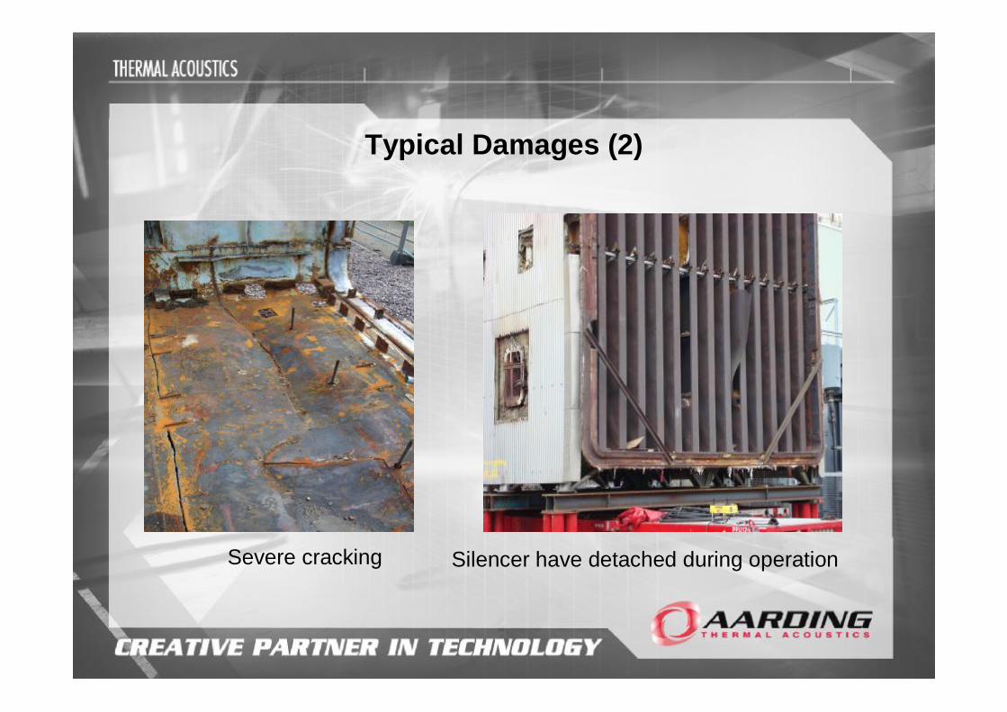
Typical Damages (2)
Silencer have detached during operationSevere cracking

Typical Damages (3)
Ducting plates have split Buckling of plate sections

Typical Damages (4)
Further evidence of damage due to thermal shock

Upgrade Programs
• Analysis & Flow Modelling– Supporting Cyclic Power Plant Operation– FEA studies
• to eliminate thermal shock for the silencer supports • overall strength calculations of casing and fluegas silencers
• “cold casing design” option– utilising only internal insulation.– long term internal insulation integrity – safer operating regime – significantly reduced maintenance down time.

Examples of Analysis & Flow Modelling
Flow ModelingStress Calculations
Silencer Support
Stress Calculation Casing
Stress CalculationsFluegas Silencers

Example of upgraded Duct Design

FABRICATION OF DUCTING
• State of the Art fabrication facilities– Larger manufactured and Pre Fabricated
modules – minimizing installation time and Power Plant
Downtime– Reducing Risk by performing shop Trial Fit’s
before installation
• Transport and site logistics– main driver for extent of “Pre Fabrication”
• Site works– Experienced and certified ATA supervisors, HSE
and project managers– Cooperating with experienced local Installation
companies

FABRICATION OF NEW FLUE GAS SILENCERS
• IN-HOUSE engineering– In line with customer specifications– Modular Design adaptable to
specific requirements
• IN HOUSE Manufacturing– Dedicated ATA factory in Nunspeet

REDUCING DOWNTIME / OVERHAUL TIME
- In House Engineering to select best technical & operational options- Advance Project Planning- Site Logistics Planning- Modular design of the replacement ducting - Local Support Companies- Close cooperation with Site and Site Engineers
Completing the project within the critical path of the hot gas path inspection of the gas turbine
Gas Turbine GE Frame 9E Exhaust Duct Replacement Programme
Case Study in Photographs
Report from a Project in the UK
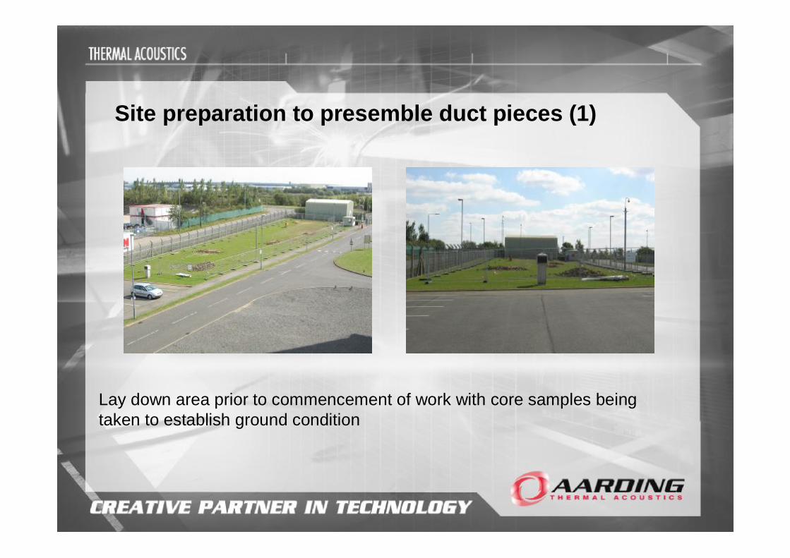
Site preparation to presemble duct pieces (1)
Lay down area prior to commencement of work with core samples being taken to establish ground condition
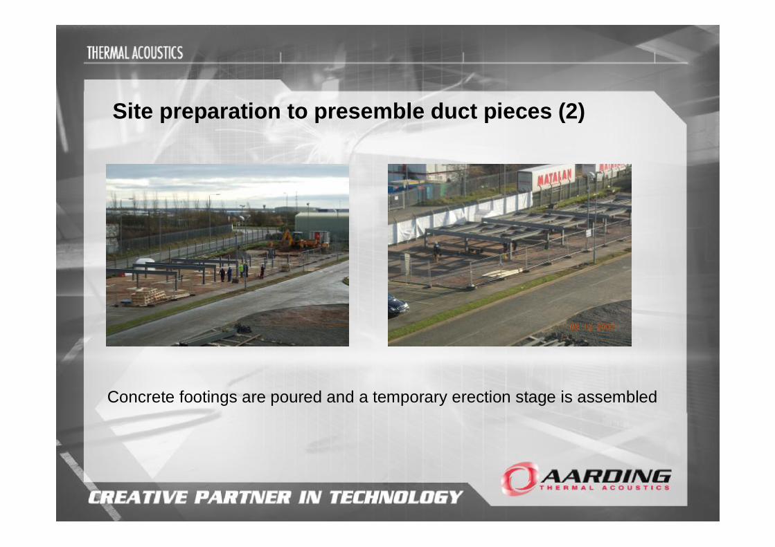
Site preparation to presemble duct pieces (2)
Concrete footings are poured and a temporary erection stage is assembled
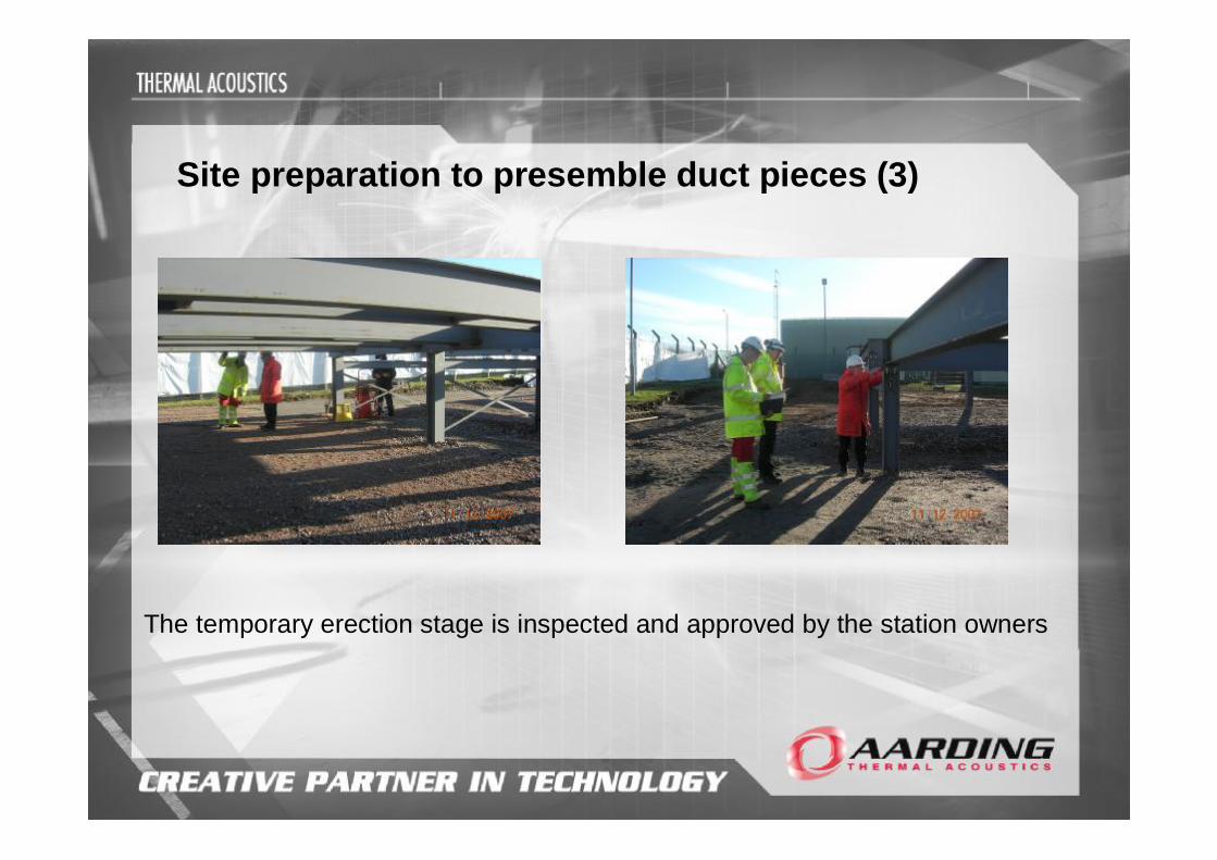
Site preparation to presemble duct pieces (3)
The temporary erection stage is inspected and approved by the station owners

Scaffolding is erected around the stage to allow the pre-fabrication of the modular duct sections
Preparation to receive duct pieces

Arrival of prefabricated duct pieces
Prefabricated / modular replacement duct sections are delivered to site

Lifting prefabricated duct pieces
Modular duct section is lifted onto stage for pre-assembly
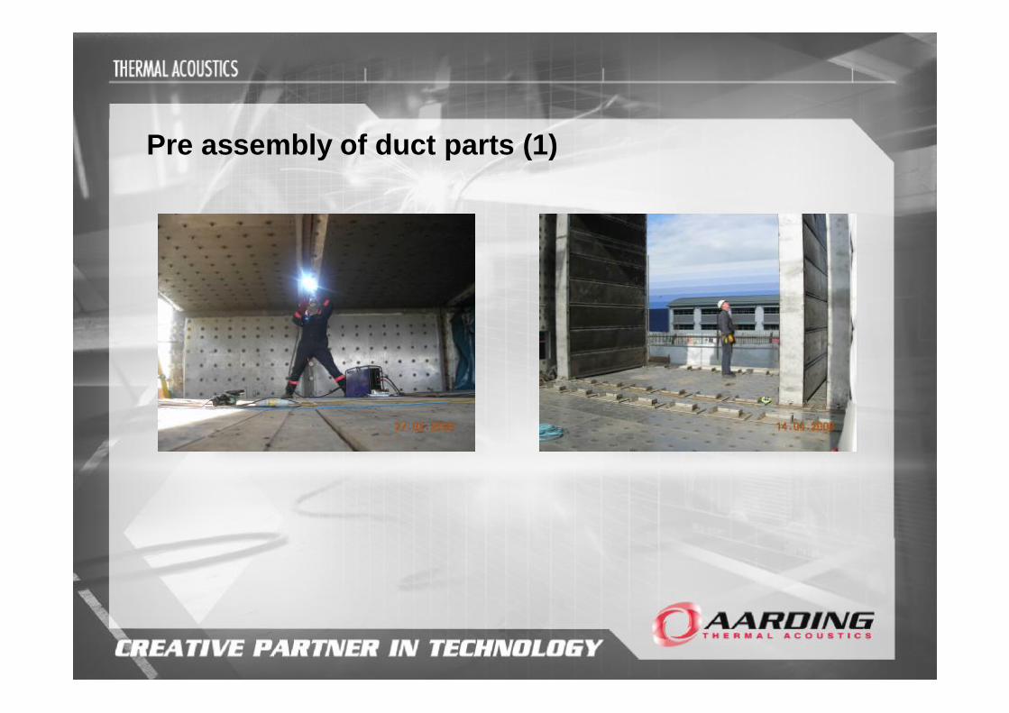
Pre assembly of duct parts (1)

Pre assembly of duct parts (2)
Replacement duct sections under assembly

Installation of new flue gas silencers
Dedicated lifting equipment is used to assemble silencer sections

Pre assembly of duct parts (3)
Replacement duct sections under assembly

Completion of pre assembly phase
Completed duct sections prior to installation
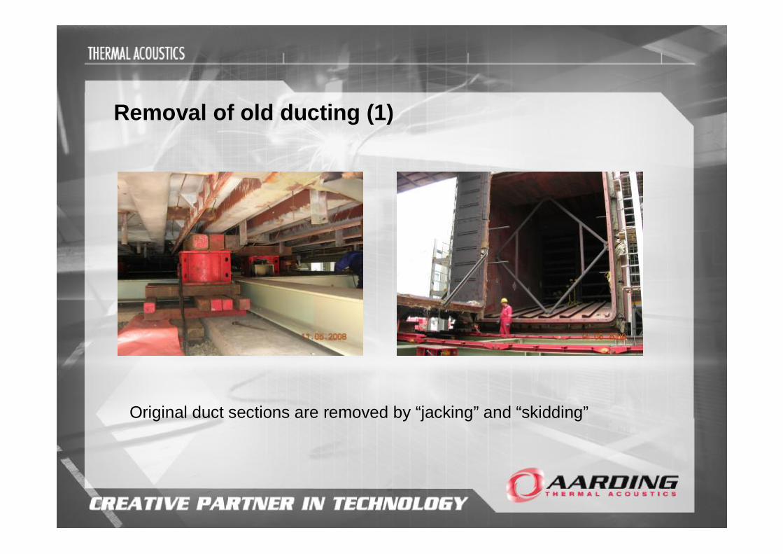
Removal of old ducting (1)
Original duct sections are removed by “jacking” and “skidding”
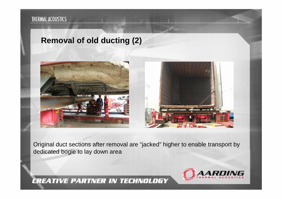
Removal of old ducting (2)
Original duct sections after removal are “jacked” higher to enable transport by dedicated bogie to lay down area

Removal of old ducting (3)
Due to the poor state of the silencers “bracing” is required to facilitate safe removal
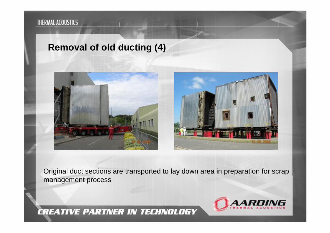
Removal of old ducting (4)
Original duct sections are transported to lay down area in preparation for scrap management process

Installation of new duct pieces (1)
Replacement duct sections are transported from lay down area for installation
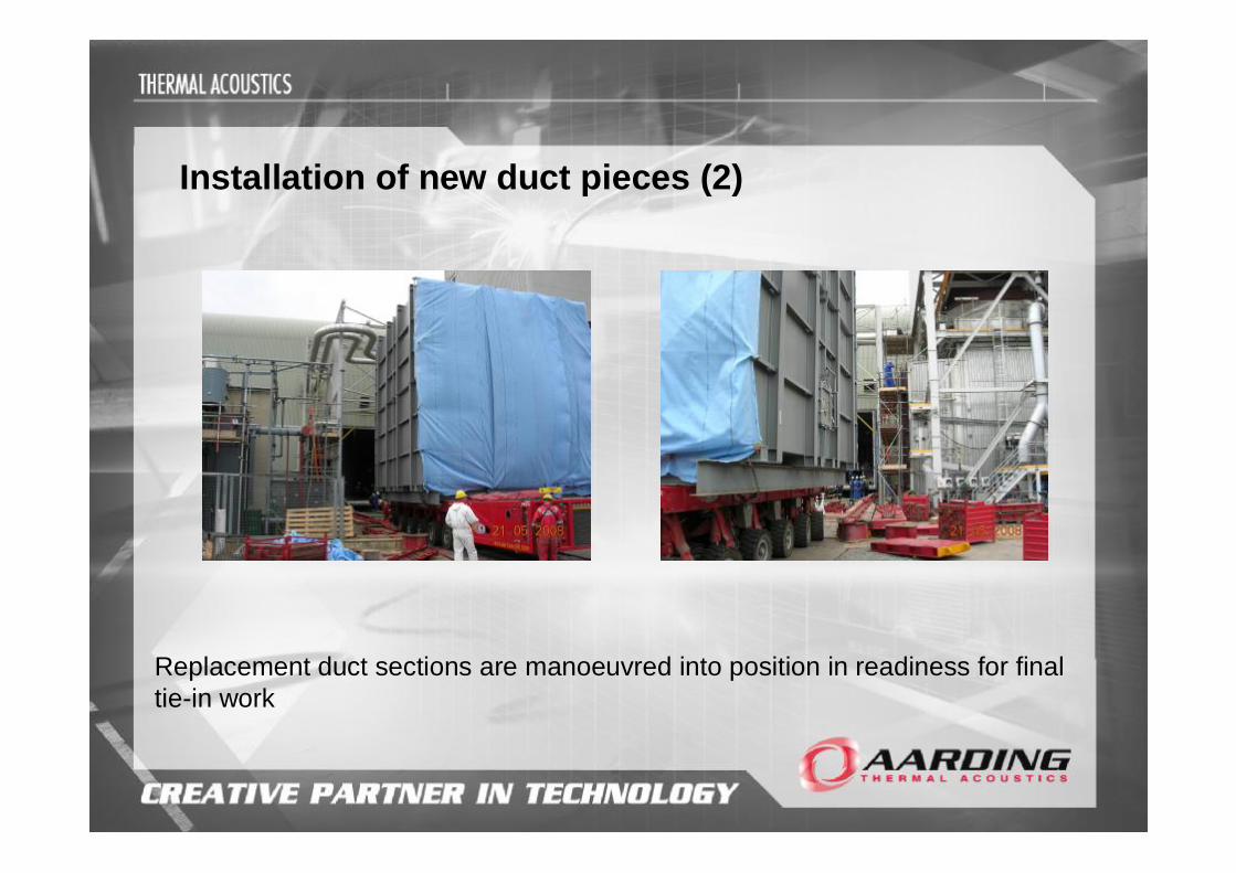
Installation of new duct pieces (2)
Replacement duct sections are manoeuvred into position in readiness for final tie-in work
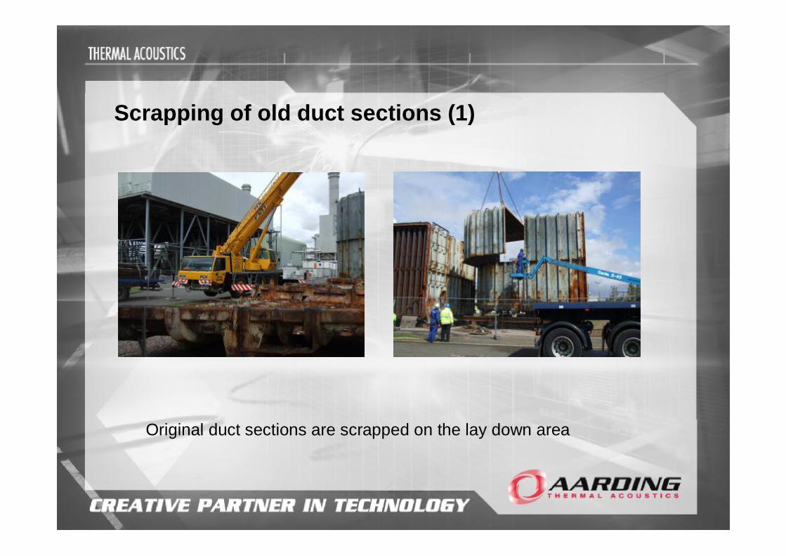
Scrapping of old duct sections (1)
Original duct sections are scrapped on the lay down area

Scrapping of old duct sections (2)
The scrap duct sections are cut and removed from site for recycling / processing

Construction (Design and Management) Regulations 2007
Improve health and safety in our industry Have the right people for the right job at the right time to manage the risks
on site Focus on effective planning and managing risk - manage the risk not the
paperwork

Industrieweg 59P.O. Box 658070 AB NunspeetThe NetherlandsTel: +31 – (0)341 – 252635Fax: +31 – (0)341 – 262112Web: http://www.ata-bv.com
Top Related