


Languages
Pages
Legal


May 1986U.S. NUCLEAR REGULATORY COMMISSION
CREGULATORY GUIDE -*0*O OFFICE OF NUCLEAR REGULATORY RESEARCH
REGULATORY GUIDE 3.56 (Task CE 309-4)
GENERAL GUIDANCE FOR DESIGNING, TESTING, OPERATING, AND MAINTAINING EMISSION CONTROL DEVICES AT URANIUM MILLS
A. INTRODUCTION
Regulations applicable to uranium milling are contained
in 10 CFR Part 20, "Standards for Protection Against Radi
ation," and in 10 CFR Part 40, "Domestic Licensing of
Source Material."
Paragraph 20.1(c) of 10 CFR Part 20 states that licensees
should make every reasonable effort to keep radiation
exposures, as well as releases of radioactive material to
unrestricted areas, as low as is reasonably achievable.
Paragraph 20.105(c) of 10 CFR Part 20 requires that licens
ees engaged in uranium fuel cycle operations subject to
the provisions of 40 CFR Part 190, "Environmental Radia
tion Protection Standards for Nuclear Power Operations," comply with that part. Part 190 of Title 40 requires that
the maximum annual radiation dose to individual members
of the public resulting from fuel cycle operations be lim
ited to 25 millirems to the whole body and to all organs
except the thyroid, which must be limited to 75 millirems.
Criterion 8 of Appendix A to 10 CFR Part 40 requires that
milling operations be conducted so that all airborne efflu
ent releases are reduced to levels as low as is reasonably. achievable.
Air in the immediate vicinity of such uranium milling operations as ore crushing, ore grinding, and yellowcake dry
ing and packaging frequently contains radioactive materials
in excess of that permissible for release to unrestricted areas. Emission control devices are installed in ventilation
systems of uranium mills to limit releases of these radioactive materials to the environment.
General guidance for filing an application for an NRC
source material license authorizing uranium milling operations is provided in § 40.31 of 10 CFR Part 40. An appli
cant for a new license or renewal of an existing license for a
uranium mill is required by § 40.31 to provide detailed
USNRC REGULATORY GUIDES
Regulatory Guides are issued to describe and make available to the public methods acceptable to the NRC staff of Implementing specific parts of the Commission's regulations, to delineate techniques used by the staff in evaluating specific problems or postulated accidents or to provide guidance to applicants. Regulatory Guides are not substitutes for regulations, and compliance with them is not required. Methods and solutions different from those set out in the guides will be acceptable If they provide a basis for the
.- findings requisite to the issuance or continuance of a permit or license by the Commission.
This guide was issued after consideration of comments received from the public. Comments and suggestions for improvements In these guides are encouraged at all times, and guides will be revised, as appropriate, to accommodate comments and to reflect new Information or experience.
Written comments may be submitted to the Rules and Procedures Branch, DRR, ADM, U.S. Nuclear Regulatory Commission, Washington, DC 20555. _
information on the proposed equipment, facilities, and procedures at the installation. This information is used by
the NRC to determine whether the applicant's proposed equipment, facilities, and procedures are adequate to protect
the health and safety of the public and and to determine if
they will significantly affect the quality of the environment.
Calculations by the NRC of the environmental impact from
the proposed uranium milling operations are based on the
estimated rate of production of radioactive airborne partic
ulates adjusted to reflect the removal efficiency of the
emission control devices installed in the plant ventilation
systems. This requires reliable information on the efficiency of these devices. It also requires reliable information on the
production of airborne radioactive particulates during the proposed operations.
Section 40.65 of 10 CFR Part 40 requires mill operators to submit semiannual reports to the NRC specifying the
quantity of each of the principal radionuclides released to
unrestricted areas in gaseous effluents. This information
may be used by the NRC to estimate maximum potential
annual radiation doses to the public resulting from effluent
releases and thereby determine compliance with paragraphs
20.1(c) and 20.105(c) of 10 CFR Part 20 and with Crite
rion 8 of Appendix A to 10 CFR Part 40. The quantity of radionuclides released is based on scheduled sampling of
effluents discharged into exhaust stacks. The reliability of
these data for estimating radiation exposures depends on
maintaining uniform operation of the emission control
devices during the reporting time interval because these
effluents are not continuously sampled.
All emission control devices used in uranium mill ventila
tion systems need to perform reliably under expected oper
ating conditions to meet the objectives discussed above. This
guide describes procedures acceptable to the NRC staff for
designing, testing, operating, and maintaining these emission
control devices to ensure the reliability of their performance.
The guides are issued in the following ten broad divisions:
1. Power Reactors 6. Products 2. Research and Test Reactors 7. Transportation 3. Fuels and Materials Facilities 8. Occupational Health 4. Environmental and Siting 9. Antitrust and Financial Review 5. Materials and Plant Protection 10. General
Copies of Issued guides may be purchased from the Government Printing Office at the current GPO price. Information on current GPO prices may be obtained by contacting the Superintendent of
Documents, U.S. Government Printing Office, Post Office Box 37082, Washington, DC 20013-7082, telephone (202)275-2060 or (202)275-2171.
Issued guides may also be purchased from the National Technical Information Service on a standing order basis. Details on this service may be obtained by writing NTIS, 5285 Port Royal Road, Springfield, VA 22161.

Any information collection activities mentioned in this regulatory guide are contained as requirements in 10 CFR Parts 20 or 40, which provide the regulatory basis for this guide. The information collection requirements in 10 CFR Parts 20 and 40 have been cleared under OMB Clearance Nos. 3150-0014 and 3150-0020, respectively.
B. DISCUSSION
The milling of uranium ores results in the production of airborne particulates containing uranium and its daughters in several areas of a typical uranium mill. These areas encompass (1) ore storage, handling, and crushing; (2) ore grinding, leaching, and concentrating processes; (3) yellowcake precipitation, drying, and packaging, and (4) miscellaneous mill locations such as maintenance shops, laboratories, and general laundries. Milling operations must be conducted so that all airborne effluent releases are reduced to levels as low as is reasonably achievable (ALARA). The primary means of accomplishing this is the control of emissions at the source.
The most significant sources of radioactive airborne particulates occur in ore handling and crushing areas and in yellowcake drying and packaging areas. These sources are generally controlled by separate ventilation systems in each area that remove these airborne particulates through local hoods, hooded conveyor belts, etc., into emission control devices where they are removed from the air streams. The cleaned air is then discharged by fans into the atmosphefe through local exhaust stacks.
Emission control devices are available in a wide range of designs to meet variations in air cleaning requirements. Degree of removal required, quantity and characteristics of the contaminant to be removed, and conditions of the air stream all have a bearing on the device selected for any given application. Emission control devices used at ore crushing and grinding operations include bag or fiber filters (baghouses), orifice or baffle scrubbers, and wet impingement scrubbers. Water spray systems are also used at these operations to minimize the generation of dust. Wet impingement scrubbers or venturi scrubbers are generally employed at yellowcake drying and packaging areas.
All emission control devices used in a uranium mill ventilation system need to be designed for reliable performance under the expected operating conditions. Initial testing and proper maintenance are primary factors in ensuring the reliability of these components. Periodic testing during operation to verify the efficiency of these components is another important means of ensuring reliability. Built-in features that will facilitate convenient in-place testing of these devices are important in ventilation system design.
Emission control devices used in a uranium mill ventilation system need to be sufficiently instrumented
to measure and monitor their operating characteristics. Frequent checks of all significant operating parameters are necessary to determine whether or not conditions are within a range prescribed to ensure that this equipment is operating consistently near peak efficiency. When checks indicate that the equipment is not operating within this range, it is necessary to take action to restore parameters to the prescribed range. To ensure that timely actions are taken, instrumentation is often supplemented by audible alarms that are preset to signal when prescribed operating range limits are exceeded. When the required actions cannot be taken without shutdown and repair of this equipment, it will be necessary to suspend milling operations that are the source of the emissions until corrective actions have been taken. Criterion 8 of Appendix A to 10 CFR Part 40 requires suspension of yellowcake drying and packaging operations as soon as practicable when shutdown and repair of the emission control system is necessary. The installation of automatic shutdown instrumentation on processes and systems at which operating parameters on emission control devices may exceed acceptable limits could prevent excessive releases that may result from continuous operations under these circumstances, e.g., those associated with the production of yellowcake. The installation of backup or redundant emission control systems would permit continuous operation during repair and maintenance of the primary system.
A preventive maintenance program is important for emission control devices used in uranium mill ventilation systems. A program designed to identify deficiencies in operation of these devices so that corrective action can be taken to reduce the frequency of off-normal operation can provide a measure of confidence in the operating characteristics of these devices. This program may require periodic updating to reflect actual in-plant experience, equipment manufacturers' guidelines, and NRC guidance. For example, a preventive maintenance program can consist of the equipment supplier's recommendations supplemented by provisions derived from the licensee's own routine inspection and maintenance records.
The key to proper maintenance of emission control devices is frequent inspection. It is important that a regular program of inspection be established and followed and records be kept of all inspections and the resulting maintenance. Inspection intervals will depend on the type of emission control device, the manufacturer's recommendation, and the process area where the unit is installed. These inspections need to be performed as frequently as experience shows to be necessary but not less than annually.
Considerable maintenance time can be expended on trouble shooting and correction of malfunctions of emission control devices. The ability to locate and correct malfunctioning components of these devices requires a thorough understanding of the system.
3.56-2

Throughout the manufacturing industry, there are
many models of each type emission control device used
at uranium mills. These models range in size in order
to meet the different air capacity needs at the mills. In
addition, some design features of each manufacturer are
unique. Accordingly, the specific design and the testing,
operating, and maintenance procedures for each model
are beyond the scope of this guide. General guidance is
presented, however, for each type of emission control
device based on typical models in present-day use.
Background information for this guidance can be found
in the Bibliography. The licensee may substitute proce
dures based on specific operating parameters of the
model in use at the facility for those described in this
guide.
1. DESIGN AND OPERATION
1.1 Bag or Fabric Filters (Baghouses)
Bag or fabric filters, usually in the form of baghouses,
remove particulates from a gas stream by filtering the
airborne particulates (by impaction or diffusion) through
a porous flexible fabric made of a woven or felted
material. These collected particles form a structure of
their own, supported by the filter, and have the ability
to intercept and retain other particles. The increase in
retention efficiency is accompanied by an increase in
pressure drop through the filter. The baghouses are
equipped with one of several automatic cleaning mecha
nisms for periodically dislodging collected material from
filter components to prevent excessive resistance to the
gas flow (i.e., excessive pressure drop) that would
otherwise develop. The dislodged material settles in
storage hoppers before the filter components are placed
back on stream. The automatic cleaning cycle can be
initiated by either a differential pressure switch or a
timer, which may be interlocked with the main fan
motor for the baghouse.
The cleaning mechanisms employed in baghouses are
based on either mechanical shaking of the filter compo
nents or pneumatic vibration of these components
by high-pressure air applied in reverse flow, reverse jet,
or reverse pulse modes. The effectiveness of these
compressed air systems depends on maintaining a suffi
cient reservoir of compressed air at the pressure speci
fied by the baghouse manufacturer. Higher pressures
than specified could cause failure of the filter fabric,
while lower pressures can result in poor filter cleaning.
These problems are minimized by pressure-regulating
devices used in the compressed air systems.
The most critical parameter to be observed during
baghouse operation is the pressure drop. Proper operation
of the baghouse requires, at a minimum, maintaining the
differential pressure of this device in the correct range
specified by the manufacturer. A manometer or a
differential-pressure gauge and transmitter are usually
provided for this purpose. This instrumentation is often
supplemented by an audible alarm system designed to
signal and alert mill operators when prescribed differentialpressure ranges are exceeded. Lower differential pressures
indicate potential deficiencies such as damaged filters or
other air bypass channels that should be corrected.
Higher differential pressures indicate that cleaning opera
tions are inadequate. This can be corrected by increasing
the frequency of the automatic cleaning cycle through
adjustment of the differential-pressure switch or timer of
the baghouse installation.
1.2 Wet Scrubbers
Wet scrubbers remove particulates from a gas stream
by effecting intimate contact between the gas stream
and a scrubbing liquor, usually water. The basic opera
tions that take place within a wet scrubber are (1)
saturation of the incoming gas, (2) contacting and
capture of the particulates in the scrubbing liquor, and
(3) separating the entrained particulate-laden liquid from
the gas stream. The basic types of wet scrubbers are
distinguished by the mechanisms used for transfer of
particulates from the gas stream to the liquid stream.
Most scrubber systems require some type of treatment
and disposal of the particulate-laden scrubbing liquor.
Several water spray systems may be used in wet
scrubber operations. Water from the main water spray
system is directed either into a screen or throat to
contact the particulate-laden gas stream. In applications
where inlet gas temperatures are inordinately high, pre
conditioning of the incoming gas to the scrubber may
be necessary to provide adequate humidity and thereby
maintain particulate collection efficiency. This may be
accomplished by use of an auxiliary water spray system
upstream of the scrubber particulate scavenging area.
Where particulate . buildup is likely to occur in the
entrainment separator, a wash system may be necessary
to avoid this condition. The wash system is usually
composed of low-pressure spray nozzles using recycled
scrubbing liquor or fresh water for cleansing.
Orifice, wet impingement, or venturi wet scrubbers
are generally used in uranium mill ventilation systems.
In orifice-type wet scrubbers, the gas stream is made to
impinge upon a surface of scrubbing water and is then
passed through various constrictions where its velocity
may be increased and where greater liquid-particulate
interaction may occur. -The gas stream finally discharges
through a chamber section where entrained droplets are
disengaged. In wet impingement scrubbers, the gas
stream is wetted with water from low-pressure spray
nozzles in the scrubber inlet and then passed through
perforated plates at high velocity to impinge on baffle
plates or vanes where liquid droplets containing partic
ulate matter coalesce and drain to a sump. Solid particles
are washed to the sump by either intermittent or con
tinuous sprays. Prior to exiting from the scrubber, the
gas stream passes through an entrainment separator to
remove entrained liquid droplets. In a venturi scrubber,
the gas stream flows through a throatlike passage where
the gas is accelerated in velocity. The scrubbing liquor is
3.5 6-3

added at or ahead of the venturi throat and is sheared into fine droplets by the high-velocity gas stream, resulting in liquid-particulate interaction. The gas and liquor droplets then pass through a cyclone separator where entrained droplets containing particulate matter are removed from the gas stream.
Although each type of scrubber discussed above has unique design features, their collection efficiencies are influenced in similar ways by incremental changes in certain common operating parameters, principally gas and liquid flow as well as pressure drop. A decrease in either the gas or liquid flow rate could result in insufficient gas cleaning. Collection efficiency can also diminish if the liquid-to-gas flow rate ratio falls below design values. An increase in pressure drop across the scrubber will enhance the collection efficiency for the same size distribution and concentration of particulates in the gas stream. Proper operation of these wet scrubbers requires monitoring of these parameters to determine that they are within ranges prescribed to ensure equipment performance consistently near optimum collection efficiency. Instrumentation used to monitor these parameters is often supplemented by audible alarm systems designed to signal and alert mill operators of the need for corrective action when prescribed operating ranges are exceeded. In some cases automatic control systems with interlocks may be necessary. For example, the scrubber fan could be interlocked to shut down in the event of an indication of water flow failure. These circumstances would require suspending particulate-producing processes in the ventilation zone serviced by the scrubber until corrective action could be taken or switching to a redundant scrubber unit.
Daily operational data summaries on baghouse and wet scrubber performance are useful in providing a continuous record of performance of these devices. Other formats that contain equivalent information such as recorder charts can also be used for this purpose. Criterion 8 of Appendix A to 10 CFR Part 40 requires that checks of all parameters that determine the efficiency of yellowcake stack emission control equipment operation be made and logged hourly. In addition, data from checks made of all operating parameters necessary to enable timely identification of malfunctions can be of value in ensuring proper operation of baghouses and wet scrubbers and in updating preventive maintenance programs for these devices to reflect actual operating experience.
2. MAINTENANCE
2.1 Bag or Fabric Filters (Baghouses)
The frequency of needed maintenance for baghouses can be determined from manufacturers' recommendations and operating experience. In order of decreasing frequency, the principal baghouse components requiring maintenance are (1) filter bags, (2) flow controls, (3) hoppers, and (4) cleaning mechanisms. Symptoms of potential
operating problems requiring corrective maintenance are almost always one of the following: (1) excessive emissions, (2) short filter bag life, and (3) high pressure drop. These symptoms may indicate malfunctioning in more than one component. For example, high pressure drop may be attributable to difficulties with the filter bag cleaning mechanism, low compressed air pressure, high humidity, weak shaking action, loose filter bag tension or excessive reentrainment of dust. Many other factors can cause excessive pressure drop, and several options are usually available for appropriate corrective action.
2.2 Wet Scrubbers
The major maintenance problems with wet scrubbers are (1) excessive buildup of solids in the wet/dry zones and entrainment separator, (2) plugged water spray nozzles, (3) abrasion in areas of high velocity such as throats and orifices, and (4) corrosion on. scrubber vessel internal surfaces. A buildup of solids often occurs around the wet/dry interfaces of ducts where the gas stream contacts the wetted scrubber housing. Instrumentation such as liquid and gas pressure indicators can exhibit rapid solids buildup and therefore require regular cleaning to ensure proper system operation and performance. Increased pressure drop, reduced gas flow, and subsequent system malfunction are all possible consequences of a buildup -of solids in the entrainment separator. Water spray nozzles frequently wear or clog, which produces an uneven liquid pattern and requires their replacement. Venturi and impingement scrubbers tend to show signs of abrasion in areas downstream of gas and liquid acceleration. Corrosion can occur from the high moisture and airborne liquid incident on components, in particular where protective liners may have deteriorated.
A regular schedule of routine inspection of key components and operating parameters is an essential ingredient of a maintenance program for ensuring the reliability of performance of typical baghouses and wet scrubbers. Examples of some typical maintenance activities for baghouses and wet scrubbers used at uranium mills are presented in Appendices A and B, respectively. These activities are in addition to those procedures recommended by manufacturers for routine lubrication, inspection, and replacement of component parts.
3. TESTING
To ensure proper selection of emission control devices, it is necessary for potential users to supply manufacturers with a list of specifications for the given application, including gas flow rates, liquid flow rates (where scrubbers are under consideration), temperature, pressure, pressure drop, concentration of particulates, particle size distribution, emission levels, and collection efficiency. The manufacturers, in turn, should design and supply these devices based on test data already available for prototype equipment used under similar circumstances.
3.56-4

If relevant test data are not available, it is generally advisable for the manufacturer and potential user to run mutually agreed-upon pilot plant or prototype tests with a gas stream typical of the gas stream to be cleansed to ensure that proper equipment is supplied to meet the desired collection efficiency. After installation of the device, it may be tested in place to confirm its particulate removal efficiency. Periodic in-place testing will ensure continued effectiveness of the device. In this way, reliable data will be available to the licensee for estimating the environmental impact of uranium milling operations before and after the commencement of operations.
Collection efficiency for baghouses and wet scrubbers used in uranium mills is usually based on inlet and outlet particulate concentrations in a dry gas corrected to standard temperature and pressure. Inlet and outlet particulate concentrations are preferably sampled simultaneously if practicable. The procedure of choice for determination of particulate concentrations is described in Method 5, "Determination of Particulate Emissions From Stationary Sources," of Appendix A to 40 CFR Part 60, "Standards of Performance for New Stationary Sources." In -this procedure, particulate matter is withdrawn isokinetically from the gas stream and collected on a glass fiber filter maintained in a prescribed elevated temperature range. The particulate mass, which includes any material that condenses at or above the filtration temperature, is determined gravimetrically after removal of uncombined water. If a preoperational in-place determination of collection efficiency is desired, a procedure mutually acceptable to the user and manufacturer may be used.
4. QUALITY ASSURANCE
Components of uranium mills do not require a formal quality assurance program; however, particular quality assurance requirements may be imposed by the NRC as license conditions if deemed necessary to protect health. A quality assurance program for emission control devices need only be an extension of the overall quality assurance program usually submitted by an applicant for a license to ensure that the emission control devices are designed and the testing, operating, and maintenance procedures are implemented to maintain uniform operation of these devices within prescribed ranges under expected operating conditions.
C. REGULATORY POSITION
Emissions from milling operations must be controlled so that all airborne effluent releases are reduced to levels as low as is reasonably achievable. An important means of accomplishing this is by means of emission control devices in mill ventilation systems. The design and the testing, operating, and maintenance procedures for these emission control devices should ensure that these devices are operating consistently near peak opera
-' tional efficiency.
1. DESIGN AND OPERATION
In addition to the requirement in Criterion 8 of Appendix A to 10 CFR Part 40 that requires checks to be made and logged hourly of all parameters that determine the efficiency of yellowcake stack emission control equipment operation, other emission control devices should be sufficiently instrumented to monitor all operating parameters necessary to enable timely identification of malfunctions. Consideration should be given to centralizing equipment instrumentation and controls, where feasible, to facilitate ease of changing and evaluating operating parameters.
Instrumentation may be supplemented by audible alarms that are preset to signal when prescribed operating range limits are exceeded.
Consideration should be given to installation of automatic shutdown instrumentation on processes and systems so that, when operating parameters on emission control devices exceed preset limits, operations would cease.
Equipment used in the emission control system should be clearly marked to allow easy identification. Up-to-date system drawings should be available to identify the location of valves and instruments. A record of system modification or changes should also be available.
Consideration should be given to keeping records of operating data in order to evaluate system performance and to provide a basis for establishing or modifying a preventive maintenance program.
Written procedures should be available for equipment operation and for operator actions if malfunctions occur. Checkoff lists should be considered for complex or infrequent modes of operation. Some operational procedures that may be considered for typical baghouses and wet scrubbers used at uranium mills are presented in Appendix C.
Equipment operators should be instructed in the function of each device and its operating characteristics. They should also be made aware of consequences of malfunctions and misoperation as well as of corrective measures that may be taken by the operator.
Equipment operators should be made aware of modifications to the equipment, changes in procedures, and problems encountered during system operation.
2. MAINTENANCE
A preventive maintenance program should be developed and implemented to sustain proper equipment performance and to reduce unscheduled repairs. Inspections should be performed at least annually, more frequently if necessary, on all components.
3.56-5

In the development of the maintenance program, consideration should be given to the type of emission control device, the manufacturer's recommendations, and the process at which the unit is installed. This program may require periodic updating to reflect onsite maintenance experience.
Schedules and written procedures should be available for maintenance work. Maintenance personnel should be trained in the implementation of maintenance procedures. They should be trained to recognize the symptoms that indicate potential problems, to determine the cause of the difficulty, and to remedy it with the help, if necessary, of the manufacturer or other outside resource.
3. TESTING
Emission control devices should be tested in place at least annually to verify collection efficiency. Collection efficiency for baghouses and wet scrubbers used in uranium mills should be based on inlet and outlet radioactive particulate concentrations in a dry gas corrected to standard temperature and pressure. Inlet and outlet (radioactive or uranium) particulate concentrations should be sampled simultaneously, if practicable.
The test should be performed in accordance with Method 5 of Appendix A to 40 CFR Part 60 or an acceptable equivalent.
If a preoperational in-place determination of collection efficiency is desired, a procedure mutually acceptable to the user and manufacturer may be used.
4. QUALITY ASSURANCE
The overall quality assurance program submitted by an applicant for a license should include provisions for (1) documentation, review, and evaluation of design, testing, operating, and maintenance data for emission control devices and (2) timely initiation of corrective actions necessary to maintain uniform operation of these devices within prescribed ranges under expected operating conditions.
D. IMPLEMENTATION
The purpose of this section is to provide information to applicants and licensees regarding the NRC staff's plans for using this regulatory guide.
Except in those cases in which an applicant or licensee proposes an acceptable alternative method for complying with specified portions of the Commission's regulations, the methods described in this guide will be used by the NRC staff in evaluating procedures for designing, testing, operating, and. maintaining emission control devices used at uranium mills.
3.56-6

BIBLIOGRAPHY
American Industrial Hygiene Association, Air Pollution Manual, Part II-Control Equipment, American Industrial Hygiene Association, Detroit, Mich., pp. 16-18, 46-56, 70-75, 129-135, 1968.
American National Standards Institute, "Fundamentals Governing the Design and Operation of Local Exhaust Systems," American National Standard ANSI Z9.2-1979, Sections 6 and 9, New York, NY, 1980.
Cross, F. L., and H. E. Hesketh, Handbook for the Operation and Maintenance of Air Pollution Control Equipment, Technomic Publishing Co., Inc., Westport, Conn., Chapters 2 and 6, 1975.
Industrial Gas Cleaning Institute, "Operation and Maintenance of Fabric Collectors," Publication No. F-3, 1972.*
Industrial Gas Cleaning Institute, "Basic Types of Wet Scrubbers," Publication No. WS-3, 1980.*
Theodore, L., and A. J. Buonicore, Air Pollution Control Equipment: Selection, Design, Operation and Maintenance, Prentice-Hall, Inc., Englewood Cliffs, N.J., Chapters 8 and 9, 1983.
U.S. Environmental Protection Agency, "HandbookIndustrial Guide for Air Pollution Control," EPA-625/ 6-78-004, Chapter 7, 1978.
U.S. Environmental Protection Agency, "Management and Technical Procedures for Operation and Maintenance of Air Pollution Control Equipment," EPA-905/ 2-79-002, Sections 3 and 5, 1979.
*Available from the Industrial Gas Cleaning Institute, Inc., 700 N. Fairfax Street, Alexandria, VA 22314.
3.56-7

APPENDIX A
TYPICAL MAINTENANCE ACTIVITIES FOR BAGHOUSES
COMPONENT
Baghouse Housing 0
0
Compressed Air System
S
Dust Collection Hopper
Manometer
Filter Bags
ACTIVITIES
Inspect exhaust from filters for visible dust.
Inspect gasketing on filter housing to ensure against leakage.
Inspect for air leakage (low pressure) and check valves.*
Check alignment of air pulse holes with center of bag filters.*
Inspect for dust and debris buildup in ducts to hopper.
Rod out dust buildup on all accessible hopper surfaces.
Check operation of the discharge mechanism.
Inspect for blockage.
Inspect individual filter bags and attachment hardware.
S
S
S
S
S
*Activities applicable to pulse or jet baghouses. The remainder are applicable to all baghouses.
3.56-8

APPENDIX B
TYPICAL MAINTENANCE ACTIVITIES FOR WET SCRUBBERS
COMPONENT
Scrubber Body 0
S
S
Nozzles
Entrainment Separator
S
S
S
S
S
Pumps
Instruments
ACTIVITIES
Inspect for wear, particularly in areas downstream of gas and liquid acceleration.
Inspect for corrosion on all scrubber internal surfaces.
Inspect for excessive buildup, in particular in the wet/dry zone.
Inspect for buildup and damage.
Check operation.
Inspect structural supports for integrity.
Inspect pumps for wear, seal water, packing, and smooth operation.
Inspect the condition of all instruments with regard to solids buildup.
3.56-9
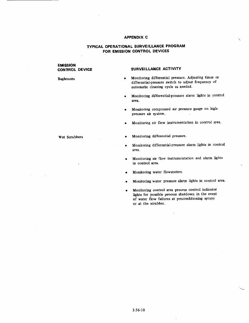
APPENDIX C
TYPICAL OPERATIONAL SURVEILLANCE PROGRAM
FOR EMISSION CONTROL DEVICES
EMISSION CONTROL DEVICE
Baghouses
Wet Scrubbers
SURVEILLANCE ACTIVITY
"* Monitoring differential pressure. Adjusting timer or differential-pressure switch to adjust frequency of
automatic cleaning cycle as needed.
"* Monitoring differential-pressure alarm lights in control area.
"* Monitoring compressed air pressure gauge on highpressure air system.
"* Monitoring air flow instrumentation in control area.
"* Monitoring differential pressure.
"* Monitoring differential-pressure alarm lights in control area.
"* Monitoring air flow instrumentation and alarm lights in control area.
"* Monitoring water flowmeters.
"* Monitoring water pressure alarm lights in control area.
"* Monitoring control area process control indicator lights for possible process shutdown in the event of water flow failures at preconditioning sprays
or at the scrubber.
3.56-10

VALUE/IMPACT STATEMENT
The NRC staff performed a value/impact assessment to determine the proper procedural approach for providing guidance on designing, testing, operating, and maintaining emission control devices at uranium mills. The assessment resulted in a decision to develop a regulatory guide describing procedures for designing, testing, operating, and maintaining emission control devices at uranium mills. The results of this assessment were included in a draft regulatory guide on this subject, CE. 309-4, that was issued for public comment in
May 1985. Comments received from the public and additional NRC staff review have shown no need to change the value/impact statement published with the proposed regulatory guide. Therefore, the value/impact statement published with the proposed guide is still applicable. A copy of the draft regulatory guide (identified by its task number, CE 309-4) and its associated value/impact statement is available for inspection and copying for a fee at the NRC Public Document Room at 1717 H Street NW., Washington, DC.
3.56-11

UNITED STATES NUCLEAR REGULATORY COMMISSION
WASHINGTON, D.C. 20555
FIRST CLASS MAIL POSTAGE Er FEES PAID
USNRC WASH. O.C.
PERMIT No. G-67
OFFICIAL BUSINESS PENALTY FOR PRIVATE USE, $300
Top Related