


Languages
Pages
Legal


RDE – LDV
ACEA Input for
EU Com working group
Brussels , 31 March 2014
ACEA RDE Expert working group
Klaus Land & Jens Franz

Agenda:
• ACEA views on RDE Family concept Albrecht Jungk
• Boundary Conditions Ingo Scholz
• Status of Instrumentation of PEMS Rainer Vogt
Agenda:
• ACEA views on RDE Family concept Albrecht Jungk
Key points:
- solution for: are all models well developed for RDE ?
- achieve a satisfied fraction of amount of RDE tests & models in a RDE family
- confirm RDE Regulation shortly after market entry

ACEA views on RDE Family concept
Albrecht Jungk

RDE Family Concept
ECE-R-83 (§9.2.4) in-service family concept to be consistently applied for • RDE Type approval
• RDE In-Service Conformity ISC
• RDE Field survey of Member States
combustion process (two stroke, four stroke, rotary) number of cylinders configuration of the cylinder block (in-line, V, radial, horizontally opposed, other) method of engine fuelling (e.g. indirect or direct injection) type of cooling system (air, water, oil) method of aspiration (naturally aspirated, pressure charged) fuel for which the engine is designed (petrol, diesel, NG, LPG, etc.). Bi fuelled vehicles may
be grouped with dedicated fuel vehicles providing one of the fuels is common. type of catalytic converter (three-way catalyst, lean NOx trap, SCR, lean NOx catalyst…) type of particulate trap (with or without); exhaust gas recirculation (with or without, cooled or non cooled) engine cylinder capacity of the largest engine within the family minus 30 %.

Schematic flow chart for PEMS test (assumption for next generation PEMS)
Test preparation
installation of measurement
crosslinking of vehicle &
measurement
installation of exhaust
adapter; if needed
Placing into operation
function checks
safety checks
Crosslinking checks
power supply for PEMS
parametrisation of
measurement categories
identification
Initial measurement
vehicle preparation
on exhaust roller test bench
load correction
preconditioning
1-2x reference cycle
vehicle dismounting
Test execution
1 valid test drive
conditioning / calibration
evaluation
Vehicle dismounting
vehicle & measurement
exhaust adapter, if needed
0,5
day
0,5
days
1
day
2
days
1
day
0,5
day
Re-measurement
(to be canceled, if
sufficient experience available)
vehicle preparation
on exhaust roller test bench
load correction
preconditioning
1-2x reference cycle
vehicle dismounting
PEMS measurement campaign for one function type

• Generation of a new RDE family:
• OEM submits self commitment for every type approval
• RDE family is described in a document similar to OBD IUPR, capable of being extended
• RDE confirmation test to be done with series start-up model shortly after market entry (type approval or series vehicle).
• Technical Service selects additional new emission types (max=2) for additional PEMS tests shortly after market entry
• Expansion of an existing RDE family (each period is 12 months)
• For each period from the creation of an RDE family, if type approvals are added to RDE-family), Technical Service selects 1 emission type from the added or extended type approvals (or 2 emission types, if there are more than 4 type approvals added to the family) for additional PEMS tests to be done by OEM shortly after market entry
• RDE family modifications have to be notified within 3 months before market entry.
RDE Testing at type approval

Example for RDE Type approval periodical testing (1 period = 12 months):
1st period 2nd period …
Type 1 emission approval No. in RDE family „A“
covered family members in RDE family „A“
Type approval
RDE vehicle family „A“ (listed in RDE certification document)
Initial RDE type approval
Example for test requirement in RDE family „A“
1st RDE test: vehicle selected by OEM
Additional RDE tests: vehicles selected by Technical Service (TS)
Approvals in initial family
No. of approvals
added
OEM RDE test with vehicle 1
Additional tests
selected by TS
1 - 1 -
2 - 4 - 1 1
≥ 5 - 1 2
1-4 - 1
≥ 5 - 2
1 - 1
1 - 2
1 - 3
2 - 1
2 - 2
2 - 3
3 - 1
3 - 2
3 - 3
Modifications in 1st period
Modifications in 2nd period

Example for a RDE-Certification document:
Type approval
RDE requirements

• In-Service family concept can be applied for RDE type approval.
• Additional RDE tests selected by Technical Service will demonstrate RDE family coverage of on-road emission behaviour.
• PEMS on-road tests need significant more effort compared to a bench test (approx. 1 week for prep., test drives, re-measurement & dismounting)
• RDE tests for type approval to be done shortly after market entry, in order to ensure a secure type approval testing and to avoid any additional risks of possible series launch delays.
• Next steps:
• Detailing of RDE test procedure incl. ISC and field survey
• RDE introduction concept incl. normalization & boundary conditions
Conclusion

Agenda:
• ACEA views on RDE Family concept Albrecht Jungk
Thank you very much for your attention

Agenda:
• Boundary Conditions Ingo Scholz
Key points:
- parameter list is defined & considered to 3 categories
- ongoing work
- first details to the 2 BC areas moderate & extended

Real Driving Emissions (RDE)
Boundary Conditions Ingo Scholz

Environmental boundary conditions Principal approach
The RDE emission limit should be linked to the emission limit for type
approval in Europe based on the NEDC test cycle. While the emissions for type approval are measured on a test bench during the NEDC test cycle the RDE emissions are measured on the road.
In order to anticipate the large variability of driving styles in comparison to well described emission bench tests the RDE test drive has to be normalised to 'normal driving'. A practical tool should normalise parameters like engine load or exhaust line temperature.

Structure of the Conformity Factor 2-Step-Modell as a Function of Temperature, Altitute, Fuel, Weight
For influences which will not be reflected by the normalisation (e.g. altitude, ambient temperature, test fuel and vehicle weight), a conformity factor (CFRDE) will have to be defined. This factor should be applied to the test average of the emissions over a complete PEMS-Trip.
Depending on the absolute values of parameters impacting variability, engine combustion and exhaust aftertreatment efficiency and the legal conformity factor, the CFRDE limit is to be composed of:
For influences which will not be reflected by the normalisation or by the conformity factor, the boundary conditions have to describe clear whether the test drive is valid or invalid.
CFRDE =CFf(T, h) + CFFuel + CFWeight
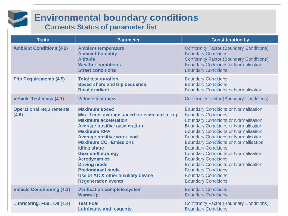
Environmental boundary conditions Currents Status of parameter list
Topic Parameter Consideration by
Ambient Conditions (4.2) Ambient temperature
Ambient humidity
Altitude
Weather conditions
Street conditions
Conformity Factor (Boundary Conditions)
Boundary Conditions
Conformity Factor (Boundary Conditions)
Boundary Conditions or Normalisation
Boundary Conditions
Trip Requirements (4.5) Total test duration
Speed share and trip sequence
Road gradient
Boundary Conditions
Boundary Conditions
Boundary Conditions or Normalisation
Vehicle Test mass (4.1) Vehicle test mass Conformity Factor (Boundary Conditions)
Operational requirements
(4.6)
Maximum speed
Max. / min. average speed for each part of trip
Maximum acceleration
Average positive acceleration
Maximum RPA
Average positive work load
Maximum CO2-Emissions
Idling share
Gear shift strategy
Aerodynamics
Driving mode
Predominant mode
Use of AC & other auxiliary device
Regeneration events
Boundary Conditions or Normalisation
Boundary Conditions
Boundary Conditions or Normalisation
Boundary Conditions or Normalisation
Boundary Conditions or Normalisation
Boundary Conditions or Normalisation
Boundary Conditions or Normallisation
Boundary Conditions
Boundary Conditions or Normalisation
Boundary Conditions
Boundary Conditions or Normalisation
Boundary Conditions
Boundary Conditions
Boundary Conditions
Vehicle Conditioning (4.3) Verification complete system
Warm-Up
Boundary Conditions
Boundary Conditions
Lubricating, Fuel, Oil (4.4) Test Fuel
Lubricants and reagents
Conformity Factor (Boundary Conditions)
Boundary Conditions

Environmental boundary conditions Definition of „typical“ instead of „normal“
“Normal” is an individual experience, and is different for everybody. In the course of AQ-evaluation, it is important from the cost efficiency that the RDE-regulation addresses the relevant parameter
In statistics and probability theory, the standard deviation shows how much variation or dispersion from the average exists.
In science, researchers commonly report the standard deviation of experimental data, and only effects that fall much farther than one standard deviation away from what would have been expected are considered statistically significant. [Source: wikipedia]
ACEA-Recommendation:
Technical restrictions
Cost efficiency of the starting value
Apply “statistics, where there are no technical restriction to ensure a remarkable offset between “moderate” and “extended” BC’s
“Moderate” covers 68% of all “possible results” equal to 1 standard deviation
“Extended” covers 95% of all “possible results” equal to 2 standard deviation

RDE-FactorExtended ‘B‘ is larger than RDE-FactorModerate ‘A‘
If a value goes in another sector during the PEMS drive the new CF will be used for the whole trip.
Structure of the Conformity Factor 2-Step-Modell as a Function of Temperature, Altitute, Fuel, Weight
‘A‘
RDE-FactorModerate ‘B‘
for typical use
Temperature T = 9 … 30 °C
Altitude h ≤ 700 m
for T = 3 … 30 °C
for h < 900 m
RDE-FactorExtended

Environmental boundary conditions Ambient temperature
0%
10%
20%
30%
40%
50%
60%
70%
80%
90%
100%
110%
-20
-15
-10 -5 0 5
10
15
20
25
30
35
Percen
tag
e D
ista
nce
Driv
en
in
EU
-27
Temperature [°C] Source: EMISIA
ACEA-Recommendation:
Ambient temperature: +3 °C to +30 °C
+9 °C to +30 °C with RDE-FactorModerate
+3 °C to +30 °C with RDE-FactorExtended
However: Temperatures below 3 °C are not practical for safety and
potential freezing issues

Environmental boundary conditions Altitude / Ambient pressure
0%
10%
20%
30%
40%
50%
60%
70%
80%
90%
100%
110%
0 200 400 600 800 1000
Percen
tag
e D
ista
nce D
riv
en
in
EU
-27
Altitude [m] Source: EMISIA

Environmental boundary conditions Altitude / Ambient pressure
The EMISIA/ACEA study assigns all distance driven in EU-27 for passenger and light-commercial vehicles into various altitude bins.
< 500 meters -> 96,0 % of all distance driven in EU27
< 800 meters -> 99,5 % of all distance driven in EU27
Even in Austria no monitoring station with an altitude higher than about 700 meters has yearly average NO2-Emissions higher than 40 μg/m3
[Source: AVISO]
[Data: UBA Wien 2009-12]
ACEA-Recommendation:
Maximum permissible altitude:
≤ 700 meters or rather pressure > 93 kPa with RDE-FactorModerate
< 900 meters or rather pressure > 91 kPa with RDE-FactorExtended

Agenda:
• Boundary Conditions Ingo Scholz
Thank you very much for your attention

Agenda:
• Status of Instrumentation of PEMS Rainer Vogt
Key points:
- PEMS PC ( PEMS light) is an adequate alternative method to confirm RDE Regulation
- outlook
Real Driving Emissions (RDE)
Status of Instrumentation Rainer Vogt
Portable Emission Measurement System (PEMS)
procedure & equipment for onroad measurements
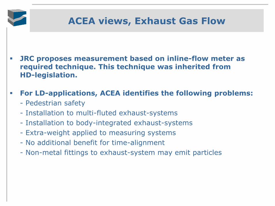
ACEA views, Exhaust Gas Flow
JRC proposes measurement based on inline-flow meter as required technique. This technique was inherited from HD-legislation.
For LD-applications, ACEA identifies the following problems:
- Pedestrian safety
- Installation to multi-fluted exhaust-systems
- Installation to body-integrated exhaust-systems
- Extra-weight applied to measuring systems
- No additional benefit for time-alignment
- Non-metal fittings to exhaust-system may emit particles

ACEA views, different exhaust geometries
ACEA views, Exhaust Gas Flow
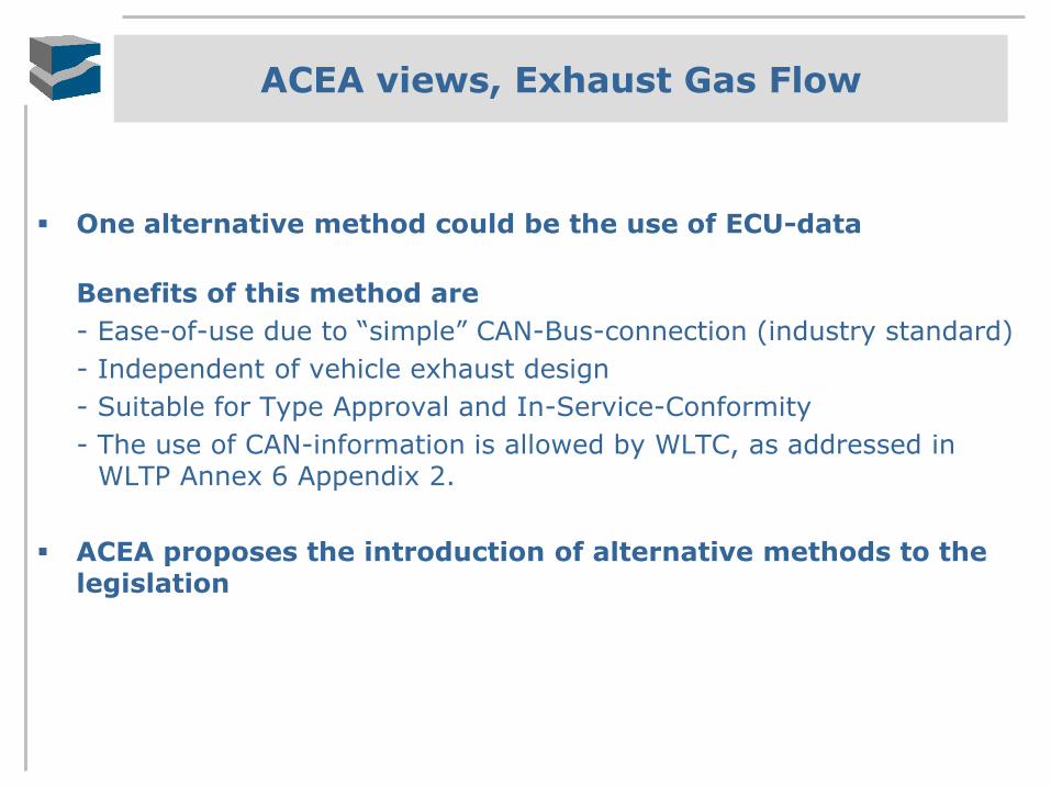
One alternative method could be the use of ECU-data
Benefits of this method are
- Ease-of-use due to “simple” CAN-Bus-connection (industry standard)
- Independent of vehicle exhaust design
- Suitable for Type Approval and In-Service-Conformity
- The use of CAN-information is allowed by WLTC, as addressed in WLTP Annex 6 Appendix 2.
ACEA proposes the introduction of alternative methods to the legislation

ACEA views, alternative exhaust flow measurement, measurement data
Difference of 2 exhaust flow meters can be more than 10% (left picture).
A validated calculated exhaust flow is reliable (right picture).
y = 0.8804xR² = 0.9641
0
10
20
30
40
50
60
70
80
90
100
0 10 20 30 40 50 60 70 80 90 100
ex
ha
ust fl
ow
me
ter
#1
[g
/s]
exhaust flow meter #2 [g/s]
WLTC - Exh. MassFlow
comparison of 2 exhaust flow meters
y = 0.9707xR² = 0.9613
0
10
20
30
40
50
60
70
80
90
100
0 10 20 30 40 50 60 70 80 90 100e
xh
au
st f
low
me
ter
[g/s
]
calc. exhaust flow based on ECU data [g/s]
WLTC - Exh. MassFlow
comparison of exhaust flow meterto calculated exhaust flow based on ECU data
ACEA views, Quality of Results
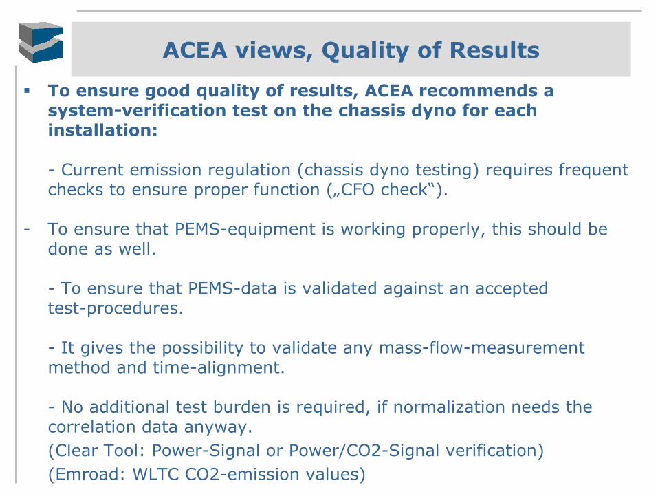
To ensure good quality of results, ACEA recommends a system-verification test on the chassis dyno for each installation:
- Current emission regulation (chassis dyno testing) requires frequent checks to ensure proper function („CFO check“).
- To ensure that PEMS-equipment is working properly, this should be done as well.
- To ensure that PEMS-data is validated against an accepted test-procedures.
- It gives the possibility to validate any mass-flow-measurement method and time-alignment.
- No additional test burden is required, if normalization needs the correlation data anyway.
(Clear Tool: Power-Signal or Power/CO2-Signal verification)
(Emroad: WLTC CO2-emission values)

ACEA views, CO / HC determination
There is no air quality problem concerning CO.
CO does not play a significant role in secondary pollutant production.
Some higher concentrations are only observed in some very dense traffic areas. Pre-Euro-vehicles, two wheel motored vehicles and other emitters are likely the cause of these emissions.
ACEA recommends the omission of
on-road CO-measurements
Type 1 and Type 6 tests already prove that the combustion process is efficient and the catalytic converter is effective quickly after the ignition.
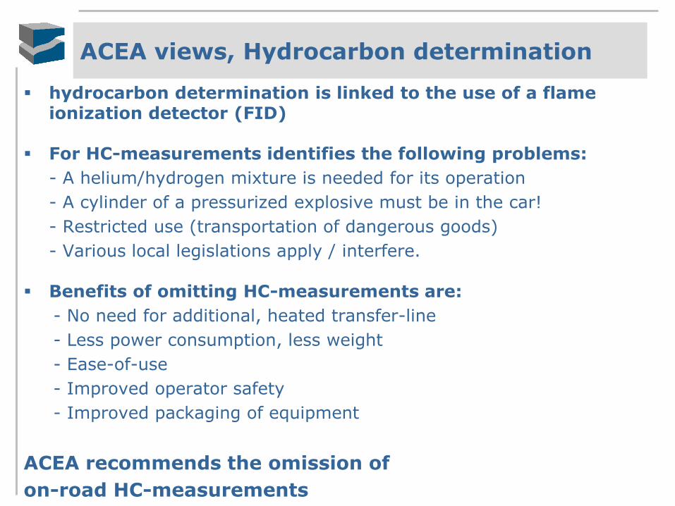
ACEA views, Hydrocarbon determination
hydrocarbon determination is linked to the use of a flame ionization detector (FID)
For HC-measurements identifies the following problems:
- A helium/hydrogen mixture is needed for its operation
- A cylinder of a pressurized explosive must be in the car!
- Restricted use (transportation of dangerous goods)
- Various local legislations apply / interfere.
Benefits of omitting HC-measurements are:
- No need for additional, heated transfer-line
- Less power consumption, less weight
- Ease-of-use
- Improved operator safety
- Improved packaging of equipment
ACEA recommends the omission of
on-road HC-measurements
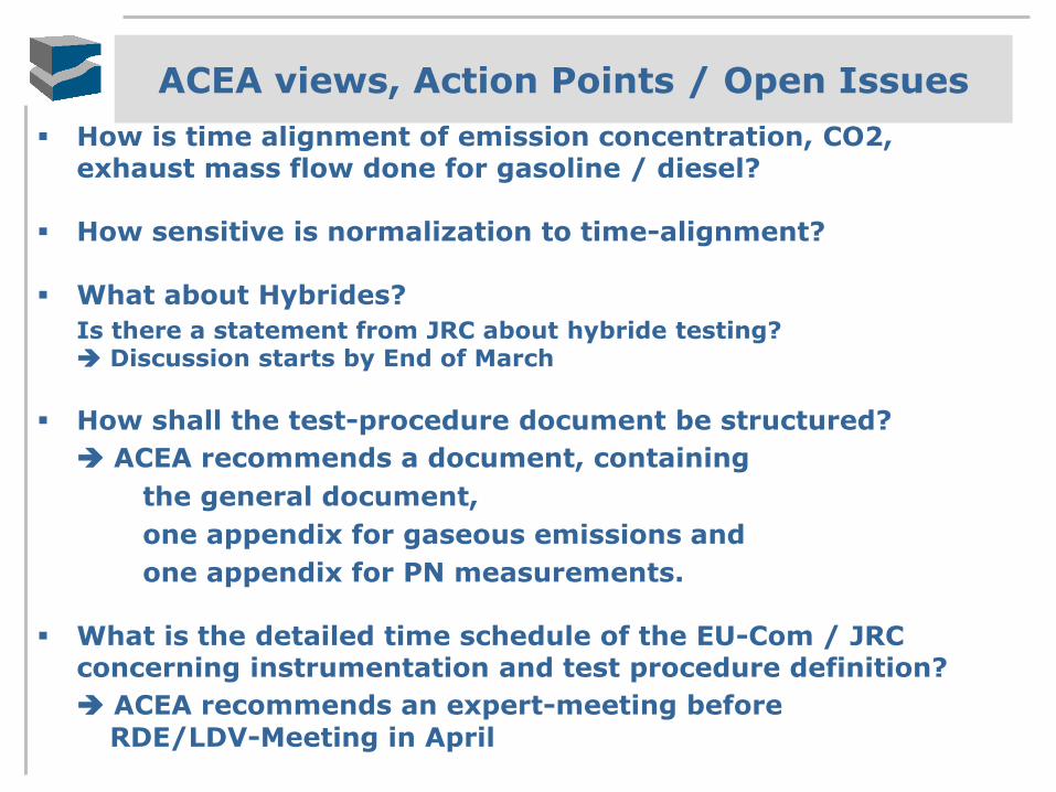
ACEA views, Action Points / Open Issues
How is time alignment of emission concentration, CO2, exhaust mass flow done for gasoline / diesel?
How sensitive is normalization to time-alignment?
What about Hybrides?
Is there a statement from JRC about hybride testing? Discussion starts by End of March
How shall the test-procedure document be structured?
ACEA recommends a document, containing
the general document,
one appendix for gaseous emissions and
one appendix for PN measurements.
What is the detailed time schedule of the EU-Com / JRC concerning instrumentation and test procedure definition?
ACEA recommends an expert-meeting before
RDE/LDV-Meeting in April

ACEA views, Timeline Instrumentation
1. ACEA / expert meeting in April 2014.
Focus: Finalizing instrumentation of gaseous emissions by June 2014.
2. ACEA / expert meeting in July 2014.
Focus: Finalizing hybrid testing and data-analysis by September 2014 (if started in April).
3. JRC provides raw data of PN-PEMS comparison to ACEA-members
4. Data analysis and verification by the ACEA-members and
PN-PEMS working group (First meeting tbd soon by JRC).
5. ACEA / expert meeting in October 2014.
Focus: Start drafting of verification and testing procedure for PN-PEMS.

Agenda:
• ACEA views on RDE Family concept Albrecht Jungk
• Boundary Conditions Ingo Scholz
• Status of Instrumentation of PEMS Rainer Vogt
Thank you very much for your attention
Top Related