


Languages
Pages
Legal


Cantilever beam under self weight
RamSeries - Valididation Case 5
Version 14.0.0
Compass Ingeniería y Sistemas http://www.compassis.comTel.: +34 932 181 989 - Fax.: +34 933 969 746 - E: [email protected] - C/ Tuset 8, 7o 2a, Barcelona 08006 (Spain)

http://[email protected] 2017

Table of Contents
RamSeries - Valididation Case 5
iiiCompass Ingeniería y Sistemas - http://www.compassis.com
Chapters Pag.
Cantilever beam under self weight 1
Model description 1
Results 3
Reference 8
Validation Summary 9

1 Cantilever beam under self weight
RamSeries - Valididation Case 5
1Compass Ingeniería y Sistemas - http://www.compassis.com
Model description
This validation example shows the analysis of a simply supported thick cantilever beam under self weight load. Results for different density meshes of 3-noded triangles and 4-noded quadrilaterals are compared against the exact analytical solution. Results are also compared with the solution given for quadratic elements, both triangles and rectangles (6 and 8 nodes, respectively).
For the sake of comparison, the vertical deflection δy of the center of the free end (point A)
and the axial stress σxat the lower fibre of the middle section (point B) are examined.
Geometrical model:
The rectangular cantilever beam geometry is defined as follows:
Point 1 Point 2 Point 3 Point 4
x 0 10 10 0
y 0 0 1 1
z 0 0 0 0

RamSeries - Valididation Case 5
2Compass Ingeniería y Sistemas - http://www.compassis.com
FEM model setup:
Boundary conditions:Two simply supported points, with only the vertical displacement restrained:
P1 (0,0,0)
P2 (10,0,0)
Loads:The only load applied is the self-weight of the cantilever beam, which is dependent on its specific weight, detailed below (Material properties).
Material:Cantilever beam properties are the following:
Thickness (t): 0.1 m
E: 2.0e8 Pa
ν: 0.2
η: 4000 N/m3
RamSeries - Valididation Case 5
3Compass Ingeniería y Sistemas - http://www.compassis.com
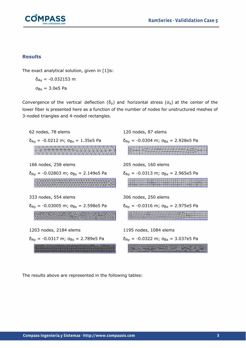
Results
The exact analytical solution, given in [1]is:
δAy = -0.032153 m
σBx = 3.0e5 Pa
Convergence of the vertical deflection (δy) and horizontal stress (σx) at the center of the
lower fiber is presented here as a function of the number of nodes for unstructured meshes of 3-noded triangles and 4-noded rectangles.
62 nodes, 78 elems
δAy = -0.0212 m; σBx = 1.35e5 Pa
120 nodes, 87 elems
δAy = -0.0304 m; σBx = 2.928e5 Pa
166 nodes, 258 elems
δAy = -0.02803 m; σBx = 2.149e5 Pa
205 nodes, 160 elems
δAy = -0.0313 m; σBx = 2.965e5 Pa
333 nodes, 554 elems
δAy = -0.03005 m; σBx = 2.598e5 Pa
306 nodes, 250 elems
δAy = -0.0316 m; σBx = 2.975e5 Pa
1203 nodes, 2184 elems
δAy = -0.0317 m; σBx = 2.789e5 Pa
1195 nodes, 1084 elems
δAy = -0.0322 m; σBx = 3.037e5 Pa
The results above are represented in the following tables:

RamSeries - Valididation Case 5
4Compass Ingeniería y Sistemas - http://www.compassis.com

RamSeries - Valididation Case 5
5Compass Ingeniería y Sistemas - http://www.compassis.com
The convergence results shown in the figures above are similar to those reported in [1].

RamSeries - Valididation Case 5
6Compass Ingeniería y Sistemas - http://www.compassis.com
Next, contourn map results concerning the vertical deflection and the horizontal stress are shown for the finest meshes (triangles and rectangles) used in the present analysis.
Vertical deflection at middle point (triangles, 1203 nodes mesh)
Sx stress at middle point (triangles, 1203 nodes mesh)

RamSeries - Valididation Case 5
7Compass Ingeniería y Sistemas - http://www.compassis.com
Vertical deflection at middle point (rectangles, 1195 nodes mesh)
Sx stress at middle point (rectangles, 1195 nodes mesh)
RamSeries - Valididation Case 5
8Compass Ingeniería y Sistemas - http://www.compassis.com
Reference
[1] Eugenio Oñate. Structural Analysis with the Finite Element Method. Linear Statics. Volume 1. Basis and Solids. Springer, 2009.

RamSeries - Valididation Case 5
9Compass Ingeniería y Sistemas - http://www.compassis.com
Validation Summary
CompassFEM version 14.0.0
Tdyn solver version 14.0.0.0
RamSeries solver version 14.0.0.0
Benchmark status Successfull
Last validation date 09/06/2017
Top Related