


Languages
Pages
Legal


International Research Journal of Engineering and Technology (IRJET) e-ISSN: 2395 -0056
Volume: 04 Issue: 05 | May -2017 www.irjet.net p-ISSN: 2395-0072
© 2017, IRJET | Impact Factor value: 5.181 | ISO 9001:2008 Certified Journal | Page 508
Quality assessment in image compression by using fast wavelet
transformation with 2D haar wavelets
Sudha Rawat
M.tech Babasaheb bhimrao ambedkar university Department of Computer Science, Babasaheb bhimrao university, Lucknow, U.P
---------------------------------------------------------------------***---------------------------------------------------------------------Abstract - Image compression is an application or techniques that facilitate to reducing the size of graphics file, without compromising on its quality and also reducing the distortion in digital image processing. Data compression is defined as the process of encoding data that reduces the overall size of data without degrade the value of data. This reduction is possible when the original dataset contains some type of redundancy, where redundant data increased the storing space in storage devices. Digital image compression is an application that studies methods for reducing the total number of bits required to represent an image. This can be achieved by eliminating the various types of redundancy that exist in the pixels values which takes extra spaces to stored the images. The objective of this paper is increased the image quality performance of evaluate a set of wavelets for image compression. Wavelet transformation is one of the best compression technique that improved compression ratio and image quality. Here in this paper we examined the fast wavelet transformation with wavelet family that is Haar wavelet transforms and reconstruct the image by using 2D haar tansformation. The Discrete Wavelet Transform (DWT) analyzes the signals at different frequency bands with different resolutions by decomposing the signal into an approximation and detail information. The study compares Advanced FWT approach in terms of PSNR, Compression Ratios and elapsed time for different Images. Complete analysis is performed at first, second and third level of decomposition using Haar Wavelet. The implementation of the proposed algorithm based on Fast Wavelet Transform. The implementation is done under the Image Processing Toolbox in the MATLAB.
Key Words: Discrete Wavelet Transform, Fast Wavelet
Transform, Approximation and Detail Coefficients, Haar
wavelets.
1.INTRODUCTION The objective of image compression is to reduce
redundancy of the image, data in order to be able to
store or transmit data in an efficient form as an original
data. Image compression is categorised in two
methods, lossy or lossless. Lossless compression is
sometimes preferred for artificial images such as
technical drawings, icons or comics where data values
are more important, compressed data and original data
must be same. This is because lossy methods
introduced compression artifacts, especially when used
at low bit rates. Lossless compression methods may
also be preferred for high value content data, such as
medical imagery, or image scans made for archival
purposes. In Lossy methods where minor loss of
fidelity is acceptable to achieve a substantial reduction
in bit rate for good quality of images. Run-length
encoding and Huffman encoding are the methods for
lossless image compression. Transform coding, where
a Fourier related transforms such as DCT or the
wavelet transform are applied that followed by
quantization and entropy coding can be cited as a
method for lossy image compression. In numerical
analysis and functional analysis, a discrete wavelet
transform (DWT) refers to wavelet transforms for
which the wavelets are discretely sampled. A lot of
work has been done in the area of wavelet
transformation based lossy image compression.
However, very little work has been done in lossless
image compression using wavelets to improve image
quality and data integrity. So the proposed
methodology of this paper is to achieve high
compression ratio with low mean square error in
images using 2D-Haar Wavelet Transform by applying
different compression thresholds for the wavelet
coefficients. That is, different compression ratios are
applied to the wavelet coefficients belonging in the
different regions of interest, in which belonging in the
different regions of interest, in which either each
wavelet domain band of the transformed image. Fast
wavelet transform (FWT) is a mathematical algorithm
designed to turn a sequence of coefficient based on an
orthogonal basis of small finite waves, or wavelets.
International Research Journal of Engineering and Technology (IRJET) e-ISSN: 2395 -0056
Volume: 04 Issue: 05 | May -2017 www.irjet.net p-ISSN: 2395-0072
© 2017, IRJET | Impact Factor value: 5.181 | ISO 9001:2008 Certified Journal | Page 509
The DWT of a signal is calculated by passing it
through a series of filters. First the samples are passed
through a low pass filter with impulse
response resulting in a convolution of the two
samples:
The signal also decomposed simultaneously using
a high-pass filter . The outputs giving the detail
coefficients (from the high-pass filter h) and
approximation coefficients (from the low-pass g). It is
important that the two filters are related to each other
and they are known as a quadrature mirror filter
(QMF).
However , since half the frequencies of the signals has
been removed, half samples can be discarded
according to Nyquist’s rule. After then, The filter output
of the low pass is subsampled by 2 and further
processed by passing it again through a new low pass
filter and high pass filter with half the cut-off
frequency of the previous one, i.e.
[ ]=
[ ]=
This decomposition has half the time resolution since
only half of each filter output characterised the signal.
However, each output has half the frequency band of
the input, so the frequency resolution has been
doubled.
With the sub sampling (disambiguation needed)
operator .
The above summation can be written more concisely.
=
=
However computing a complete its
operation with subsequent down sampling
would waste computation time.
This decomposition is repeated to further increase the
frequency resolution and the approximation
coefficients decomposed with high pass and low pass
filters and then down-sampled. This processed is
represented as a binary tree with nodes representing a
sub-space with a different time-frequency localisations.
The tree is known as a filter bank.
At each level of filter bank the signal is decomposed
into low and high frequencies. Due to the
decomposition process the input signal must be a
multiple of where is the number of levels used in
filter bank.
2. Fast wavelet transform
a mathematical algorithm that designed to turn
a waveform or signals in the time domain into
a sequence of coefficients based on an orthogonal
basis of small finite waves, or wavelets. The transform
can be easily extended to the multidimensional signals,
such as images, where the time domain is replaced
with the space domain.
It has theoretical foundation the device of a finitely
generated, orthogonal multi resolution analysis (MRA).
In the terms of given there, one selects a sampling
scale J with sampling rate of 2J per unit.
Interval, and projects the given signal f onto the space
; in theory by computing the scalar products
The Fast Wavelet Transform is
International Research Journal of Engineering and Technology (IRJET) e-ISSN: 2395 -0056
Volume: 04 Issue: 05 | May -2017 www.irjet.net p-ISSN: 2395-0072
© 2017, IRJET | Impact Factor value: 5.181 | ISO 9001:2008 Certified Journal | Page 510
=
Where is the scaling function of the chosen wavelet
transform; in practically by any suitable sampling
procedure under the condition that the signal is highly
over sampled, so
is the orthogonal projection or at least some good
approximation of the original signal in .
The MRA is characterised by its scaling sequence such
as:
Or as a Z-transform,
And its wavelet sequence is:
b= ) or
(some coefficients might be zero). Those allowed to
compute the wavelet coefficients , at least some
range as k=M,...,J-1, without having to approximate the
integrals in the corresponding scalar products.
compute those coefficients from the first
approximation Instead, one can directly, with the
help of convolution and decimation operators,.
Forward DWT
One computes recursively, starting with the coefficient
sequence and counting down from k=J-1 to
some M<J,
or And
or
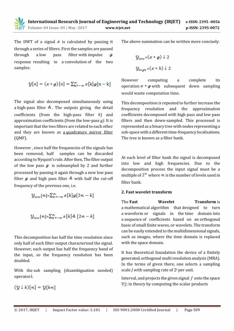
Fig1: block diagram of filter analysis
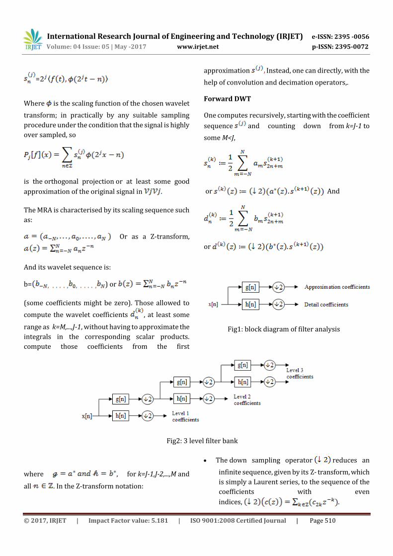
Fig2: 3 level filter bank
where , for k=J-1,J-2,...,M and
all . In the Z-transform notation:
The down sampling operator reduces an
infinite sequence, given by its Z- transform, which
is simply a Laurent series, to the sequence of the
coefficients with even
indices, .

International Research Journal of Engineering and Technology (IRJET) e-ISSN: 2395 -0056
Volume: 04 Issue: 05 | May -2017 www.irjet.net p-ISSN: 2395-0072
© 2017, IRJET | Impact Factor value: 5.181 | ISO 9001:2008 Certified Journal | Page 511
The starred Laurent-polynomial denotes the
adjoint filter, it has time-reversed adjoint
coefficients, . (The
adjoint of a real number being the number itself,
of a complex number being its conjugate, of a real
matrix the transposed matrix, of a complex matrix
its hermitian adjoint).
Multiplication is form of polynomial multiplication,
which is equivalent to the convolution of the
coefficient sequences.
It follows that
This is the orthogonal projection of the original
signal f or at least of the first
approximation onto the subspace , that is,
with sampling rate of 2k per unit interval. The
difference to the first approximation is given by:
+. . . .+ .
where the difference or detail signals are computed
from the detail coefficients as:
with denoting the mother wavelet of the wavelet
transform.
Inverse DWT
Given the coefficient sequence for some M<J and
all the difference sequences , k=M,...,J-1, one
computes recursively,
Or
for k=J-1,J-2,...,M and all . In the Z-transform
notation:
The upsampling operator creates zero-filled
holes inside a given sequences. That is, every second
element of the resulting sequence is an element of the
given sequence, every other second element is zero
or . This linear operator is,
in the Hilbert space , the adjoint to the
downsampling operator
3. Haar wavelet transform
Haar wavelet compression is very simple and an
efficient way to perform both lossless and lossy image
compression. It relies on averaging the pixels values
and differencing values in an image matrix to produce a
matrix which is sparse or nearly sparse. A sparse
matrix is a matrix in which a large portion of its entries
values are 0. A sparse matrix can be stored in an very
efficient manner leading to the smaller file sizes of
image. By using haar wavelet compression we
concentrate on grayscale images; however, rgb images
can be handled by compressing each of the color layers
with separately. The basic method is to start with any
image A, which can be regarded as an m×n matrix with
values 0 to 255. In Matlab, this would be a matrix with
an unsigned 8-bit integer values. We then subdivide to
image into 8×8 blocks, padding as necessary. This is the
8×8 blocks that we work with. Haar wavelet basis can
be used to represent the image by computing a wavelet
transform. To do this, first compute average the pixels
together, pair wise, is calculated to get the new lower
resolution image with pixel values [14, 10, 6, 2]. This
single number is used to recover the first two pixels of
our original four-pixel image. Similarly, the first detail
coefficient is -1, since 14 + (-1) = 13 and 14 - (-1) = 15.
Thus, the original image is decomposed into a lower

International Research Journal of Engineering and Technology (IRJET) e-ISSN: 2395 -0056
Volume: 04 Issue: 05 | May -2017 www.irjet.net p-ISSN: 2395-0072
© 2017, IRJET | Impact Factor value: 5.181 | ISO 9001:2008 Certified Journal | Page 512
resolution (two-pixel) version and a pair of detail
coefficients. Repeating this process recursively on the
averages gives the full decomposition shown in table1.
Table1: decomposition to lower resolution
Thus this is the basis of one dimensional haar wavelet
transforms procedure to compute the detail
coefficients of an image matrix data. We used the way
to compute the wavelet transform by recursively
averaging and differencing coefficients, filter bank. We
can reconstruct the image to any resolution values by
recursively adding and subtracting the detail
coefficients from the lower resolution versions.
3.1. Compression of image with 2D Haar Wavelet
Techniques:
It has been shown in previous section how one
dimensional image reconstructed with any resolution
and also it can be treated as sequences of coefficients.
Alternatively, we can also think of images as a
piecewise constant functions on the half-open interval
[0, 1). To do so, there used the concept of a vector
space. A one-pixel image is just as a function that is
constant over the entire interval [0, 1). Let be the
vector space of all these functions. A two pixel image
has a two constant pieces over the intervals [0, 1/2)
and [1/2, 1). We call the space containing all these
functions . If we continue in this manner, the space
will include all piecewise-constant functions that
defined on the interval [0, 1) with constant pieces over
each of equal subintervals. Now, We think of every
one-dimensional image with pixels as an element, or
vector, in . Note that because of these vectors are all
functions are defined on the unit interval, every vector
in is also contained in . For example, we always
describe a piecewise constant functions with two
intervals as a piecewise-constant function with four
intervals, with each interval in the first function
corresponding to a pair of intervals in the second
intervals. Thus, the spaces are nested; that is, ⊂
⊂ ⊂ …… This nested set of vector spaces is a
necessary ingredient for the mathematical theory of
multiresolution analysis (MRA) [1]. It guarantees that
every member of can be represented exactly as a
member of higher resolution space . The converse,
however, is not true: not every function G(x) in can
be represented exactly in lower resolution space ; in
general there is some lost detail [2]. Now we define a
basis for each vector space . The basic functions for
the spaces are called scaling functions, are usually
denoted by the symbol. A simple basis for is given by
the set of scaled and translated box functions [3]:
where
The wavelets corresponding to the box basis are
known as the Haar wavelets, given by-
where
Resolution Averages Detail Coefficients
8 [13,15,11,9,7,5,1,3]
4 [14,10,6,2] [-1,1,1,-1]
2 [12,4] [2,2]
1 [8] [4]
International Research Journal of Engineering and Technology (IRJET) e-ISSN: 2395 -0056
Volume: 04 Issue: 05 | May -2017 www.irjet.net p-ISSN: 2395-0072
© 2017, IRJET | Impact Factor value: 5.181 | ISO 9001:2008 Certified Journal | Page 513
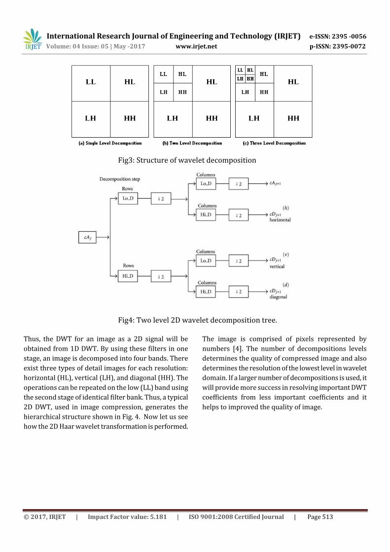
Fig3: Structure of wavelet decomposition
Fig4: Two level 2D wavelet decomposition tree. Thus, the DWT for an image as a 2D signal will be
obtained from 1D DWT. By using these filters in one
stage, an image is decomposed into four bands. There
exist three types of detail images for each resolution:
horizontal (HL), vertical (LH), and diagonal (HH). The
operations can be repeated on the low (LL) band using
the second stage of identical filter bank. Thus, a typical
2D DWT, used in image compression, generates the
hierarchical structure shown in Fig. 4. Now let us see
how the 2D Haar wavelet transformation is performed.
The image is comprised of pixels represented by
numbers [4]. The number of decompositions levels
determines the quality of compressed image and also
determines the resolution of the lowest level in wavelet
domain. If a larger number of decompositions is used, it
will provide more success in resolving important DWT
coefficients from less important coefficients and it
helps to improved the quality of image.
International Research Journal of Engineering and Technology (IRJET) e-ISSN: 2395 -0056
Volume: 04 Issue: 05 | May -2017 www.irjet.net p-ISSN: 2395-0072
© 2017, IRJET | Impact Factor value: 5.181 | ISO 9001:2008 Certified Journal | Page 514
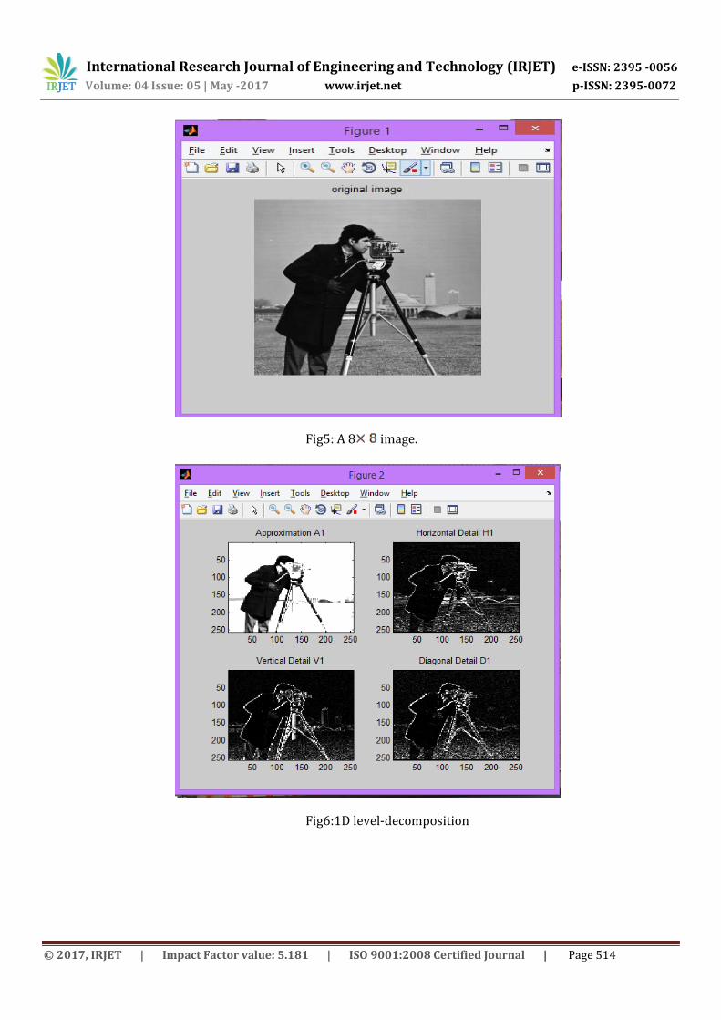
Fig5: A 8 image.
Fig6:1D level-decomposition

International Research Journal of Engineering and Technology (IRJET) e-ISSN: 2395 -0056
Volume: 04 Issue: 05 | May -2017 www.irjet.net p-ISSN: 2395-0072
© 2017, IRJET | Impact Factor value: 5.181 | ISO 9001:2008 Certified Journal | Page 515
Fig7: 1D level reconstructed image
Fig8:2D level decomposition

International Research Journal of Engineering and Technology (IRJET) e-ISSN: 2395 -0056
Volume: 04 Issue: 05 | May -2017 www.irjet.net p-ISSN: 2395-0072
© 2017, IRJET | Impact Factor value: 5.181 | ISO 9001:2008 Certified Journal | Page 516
Fig9: 2D level reconstructed image
Fig10: input and output image

International Research Journal of Engineering and Technology (IRJET) e-ISSN: 2395 -0056
Volume: 04 Issue: 05 | May -2017 www.irjet.net p-ISSN: 2395-0072
© 2017, IRJET | Impact Factor value: 5.181 | ISO 9001:2008 Certified Journal | Page 517
Fig11: output image
3.2. QUALITY MEASUREMENT
We define the compression ratio (CR) as in percentage
of number of bits in original image and compressed
image.The compression scores in percentages 26.6602,
after implement to 2D haar wavelets. It is noted here
that the hard thresholding provides the best CR. The
soft thresholding gives a better CR in comparison to
universal thresholding method. The PSNR for gray
scale image (8 bits/pixel) is defined by-
PSNR=
Where is approximation of decompressed image and
is original image and M, N are dimensions of the
image. These results are widely acceptable in most
cases except in medical application where no loss of
information is to be guaranteed. However, the PSNR is
Not adequate as a perceptually meaningful measure of
pictures quality, because the reconstruction errors
generally do not have the characteristic of signal
independent additive noise and the seriousness of the
impairments that cannot be measured by a simple
power measurement. At present in image compression,
the most widely used objective distortion measures are
the MSE and the related PSNR. They can be easly
computed to represent the deviation of the distorted
image from the original image in the pixelwise or
bitwise sense. The subjective perceptual quality
improvement includes surface smoothness, edge
sharpness and continuity, proper background noise
level, and so on.
4. CONCLUSION Image compression helps to decrease the size of image
to stored images in appropriate storage space. it helps

International Research Journal of Engineering and Technology (IRJET) e-ISSN: 2395 -0056
Volume: 04 Issue: 05 | May -2017 www.irjet.net p-ISSN: 2395-0072
© 2017, IRJET | Impact Factor value: 5.181 | ISO 9001:2008 Certified Journal | Page 518
to reduced the bits redundancy by which image takes
large space. Compressed image has a low quality after
compression applied. the wavelet transformation is
one of the best technique to improved the image
quality and also reduced distortion and enhanced the
compression performance. A low complex 2D image
compression method using Haar wavelets which is the
family of wavelet transformation, as the basis functions
along with the quality measurement of the compressed
images have been presented here . As for the further
work, the decomposition level are greatly helps to
increase the quality of image 3D haar wavelet is the
future work of this techniques which is help to
compressed the 3D image with best quality also the
tradeoff between the value of the threshold ε and the
image quality can be studied and also fixing the
correct threshold value is also of great interest.
Furthermore, finding out the exact number of
transformation level required in case of application
several image compression at one time, can be studied.
Also, more thorough comparison of various still image
quality measurement algorithms may be conducted
also decide which one is the best approach, is
considered . Though many published algorithms left a
few parameters unspecified, here good estimates of
them and simple procedures for implementation have
been provided so that it is difficult to conclude any
decisive advantage of one algorithm over another.
REFERENCES [1] Eric J. Stollnitz, Tony D. Derose and David H. Salesin,
Wavelets for Computer Graphics- Theory and Applications
Book, Morgan Kaufmann Publishers, Inc. San Francisco,
California.
[2] Robert L. Cook and Tony DeRose, Wavelet Noise, ACM
Transactions on Graphics, July 2005, Volume 24 Number 3,
Proc. Of ACM SIGGRAPH 2005, pp. 803-811.
[3] Vetterli, M. and Kovacevic, J., Wavelets and Subband
Coding, Englewood Cliffs, NJ, Prentice Hall, 1995,
http://cm.belllabs.com/who/jelena/Book/home.html.
[4] G. Beylkin, R. Coifman, and V. Rokhlin, Fast wavelet
transforms and numerical algorithms, I. Communications on
Pure and Applied Mathematics, 44(2): 141-183, March 1991.
[5]Ahmed, N., Natarajan, T., and Rao, K. R., Discrete Cosine
Transform, IEEE Trans. Computers, vol. C-23, Jan. 1974, pp.
9093.
[6] H. Marmolin, Subjective MSE measures, IEEE Trans.
Systems Man. Cybernet. 16, 1986, 486–489.
[7] C.-L. Chang and B. Girod, "Direction-adaptive discrete
wavelet transform for image compression," Image
Processing, IEEE Transactions on, vol. 16, pp. 1289-1302,
2007.
[8] W. Ding, F. Wu, X. Wu, S. Li, and H. Li, "Adaptive
directional liftingbased wavelet transform for image coding,"
Image Processing, IEEE Transactions on, vol. 16, pp. 416-
427, 2007.
[9] W. Dong, G. Shi, and J. Xu, "Adaptive nonseparable
interpolation for image compression with directional
wavelet transform," Signal Processing Letters,
IEEE, vol. 15, pp. 233-236, 2008.
[10] S-T. Hsiang and J.W. Woods, Embedded image coding
using zeroblocks of subband/wavelet coefficients and
context modeling, IEEE Int. Conf. on Circuits and Systems
(ISCAS2000), vol. 3, pp.662-665, May 2000.
Top Related