


Languages
Pages
Legal


PULVIS MINI SPRAY GB210A
PULVIS MINI BED GB210B
Instruction Manual
- Second Edition -
Thank you for purchasing " PULVIS GB Series" of Yamato
Scientific Co., Ltd.
To use this unit properly, read this "Instruction Manual" thoroughly before using this unit. Keep this instruction manual around this unit for referring at anytime.
:WARNING!:
Carefully read and thoroughly understand the important warning items described in this manual before using this unit.
Yamato Scientific Co. LTD., This paper has been printed on recycled pap

Contents 1. Safety precautions.................................................................... 1
Explanation of pictograms ............................................................. 1 List of symbols ....................................................................... 2 Warning・Cautions ................................................................... 3
2. Before using this unit.................................................................. 5 Precautions when installing the unit ..................................................... 5 Service receptacle capacity ............................................................ 8 Temperature output terminal............................................................ 8
3.Names of parts and their function........................................................ 9 Specifications of GB 210B (GB210 + GF200) ............................................. 9 Specifications of GB 210A (GB210 + GF300) ............................................ 10 Operation panel ..................................................................... 11
4. Operating procedures ................................................................ 12 Preparations ........................................................................ 12 Operating method ................................................................... 18 Operating method of GB210B......................................................... 19 Operating method of GB210B......................................................... 25 Operating method of GB210A/GB210B................................................. 28
5. Handling Precautions ................................................................ 29 Drying Method under Appropriate Condition ............................................. 30 Drying Method under Appropriate Condition ............................................. 31
6. Maintenance Method................................................................. 33 Daily Inspection and Maintenance...................................................... 33
7. Long storage and disposal ............................................................ 35 When not using this unit for long term / When disposing ................................... 35 Matters to consider when disposing of the unit ........................................... 35
8. When a trouble occurs ............................................................... 36 Safety unit and error indications ....................................................... 36 Confirmation of GB210A manual and language selection display ........................... 37 Confirmation of GB210B manual and language selection display ........................... 39 Trouble Shooting .................................................................... 41
9. After Service and Warranty ........................................................... 43 When requesting a repair ............................................................. 43
10. Specification....................................................................... 44 11.Wiring Diagram ..................................................................... 47 12. System Chart ...................................................................... 48
System Chart of GB210B ............................................................. 48 System Chart of GB210A ............................................................. 49
13. Principle of Operation ............................................................... 50 14. Replacement parts table............................................................. 51 15. List of Dangerous Substances........................................................ 55

1
1. Safety precautions Explanation of pictograms
About pictograms
A variety of pictograms are indicated in this operating instruction and on
products for safe operation. Possible results from improper operation
ignoring them are as follows.
Be sure to fully understand the descriptions below before proceeding to the
text.
Warning Caution Indicates a situation which may result in minor injury (Note 2) and
property damages (Note 3.)
(Note 1)Serious injury means a wound, an electrical shock, a bone fracture or intoxication that may
leave after effects or require hospitalization or outpatient visits for a long time.
(Note 2)Minor injury means a wound or an electrical shock that does not require hospitalization or
outpatient visits for a long time.
(Note 3)Property damage means damage to facilities, devices and buildings or other properties.
Meanings of pictograms
This pictogram indicates a matter that encourages the user to adhere to warning (“caution” included). Specific description of warning is indicated near this pictogram. This pictogram indicates prohibitions Specific prohibition is indicated near this pictogram.
This pictogram indicates matters that the user must perform Specific instruction is indicated near this pictogram.
Indicates a situation which may result in death or serious injury (Note 1.)
2
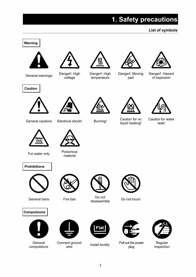
1. Safety precautions List of symbols
Warning
General warnings Danger!: High voltage
Danger!: High temperature
Danger!: Moving part
Danger!: Hazard of explosion
Caution
General cautions Electrical shock! Burning! Caution for no liquid heating!
Caution for water leak!
For water only Poisonous material
Prohibitions
General bans Fire ban Do not disassemble Do not touch
Compulsions
General
compulsions Connect ground
wire Install levelly Pull out the power plug
Regular inspection

3
1. Safety precautions Warning・Cautions
Warning
Do not use this unit in an area where there is flammable or explosive gas
Never use this unit in an area where there is flammable or explosive gas. This unit is not explosion-proof. An arc may be generated when the power switch is turned on or off, and fire/explosion may result. (Refer to page 42 “15. List of Dangerous Substances”.)
Always ground this unit Always ground this unit on the power equipment side in order to avoid electrical shock due to a power surge.
Apply the source of rated power or more Be sure to apply the source of rated power or more. Applying non-rated voltage or non-rated power supply may cause the fire or electric shock.
Prohibition of use for error If a smoke or abnormal smell may be occurred, turn off the power switch of the main unit immediately, and turn off the original power source, and finally contact to either the dealer you purchased this unit or our sales office. Leaving the failure may cause the fire or electric shock. Since the repairing of this unit is dangerous for non-specified service person, never repair the unit by the customer himself.
Do not use the power cord if it is bundled or tangled Do not use the power cord if it is bundled or tangled. If it is used in this manner, it can overheat and fire may be caused.
Do not damage power cord
Do not damage power cord by bending, pulling, or twisting forcedly. It may cause the fire or electric shock. Besides, operating the unit with the something put on the cord may cause overheat, and result in fire.
Never use an explosive or a flammable material with this unit.
Never use an explosive material, a flammable material or a material containing them. An explosion or an electrical shock may result. GB210A supports organic solvents by connecting it to the optional GAS410. Carefully read the operation manual of GAS410 and take special care for handling of organic solvents. See section “15. List of Dangerous Substances” on page 42.
Never try to touch a hot part. Some parts of the unit are hot during and immediately after operation. Take special care for possible burning.
Never try to disassemble or alter the unit. Never try to disassemble or alter the unit. A malfunction, a fire or an electrical shock may result.

4
1. Safety precautions Warning・Cautions
Caution
During a thunder storm During a thunderstorm, turn off the power key immediately, then turn off the circuit breaker and the main power. If this procedure is not followed, fire or electrical shock may be caused.
• If the electric failure shall be occurred, When power is shut off during operation (while the blower is operating or liquid is being sent) due to turning of the ELB to "OFF" or a power failure, all operation modes will reset to the initial states after recovery. When the temperature inside the chamber has been high, keep operating the blower until it cools down to 45 or below after recovery from a power failure.
• Do not perform unattended operation during activating the unit
Do not perform unattended operation during activating the unit. Since the unit is in idling status and the nozzle is blocked of after the operation using sample, the temperature around outlet is increased and the remaining sample is flown from the sample tube disconnected from the unit, and this failure may cause the indeterminism accident.
About countermeasures against static electricity
The cyclone may charge with static electricity depending on the specifc specimen used, or operating environment or conditions. Implement countermeasures against static electricity such as attaching included earth clips at three positions on the clamp at the connection of the cyclone or attaching an antistatic brush (optional) to the body of the cyclone.

5
2. Before using this unit Precautions when installing the unit
Warning1. Always ground this unit
・ Be sure to connect the earth wire (the green cable of power cord) to the grounding conductor or ground terminal to prevent accidents caused by electric leakage.
・ This unit requires a single phase 200V power supply (also supports AC220V or AC240V by selecting either of it) (See page 12 (1)) Ask the nearest electrical contractor for the power including the connecting work. The setting (connecting) work is performed following the related electrical equipment technical standard published by the corresponding country to be used this unit.
・ Do not connect the earth wire to gas or water pipes. If not, fire disaster may be caused.・ Do not connect the earth wire to the ground for telephone wire or lightning conductor. If
not, fire disaster or electric shock may be caused.
・ The power plug is not attached as standard component. Connect the earth correctly adjusting the type of the power equipment of the user.
2. Pay attention to the color of each core wire when connecting the power cord
Core Wire Color
In-house Wiring
Black Voltage Side
White Voltage Side
Be sure to check that the breaker on the power source equipment side is turned "OFF" when connecting power cord without fail. Note that the ADL311 does not attach the power plug as standard component. Select the appropriate power plug and terminal matching to the power capacity of the power source equipment to be connected, and connect them. Green Ground Side
3. Choose a proper place for installation
Do not install this unit in a place where:
Rough or dirty surface. Flammable gas or corrosive gas is generated. Ambient temperature bellow 5 or above 30°C. Ambient temperature fluctuates violently. There is direct sunlight. There is excessive humidity and dust. There is a constant vibration. Place where the water is easy-to-be splashed.
Install this unit on a stable place with the space as shown below.
50 or more
Rear side
80 or more 50 or more
100 or more
Front side
Main unit
Green (to ground terminal)
Black (to rated power supply terminal)
White (to rated power supply terminal)
Rounded terminal for M5

6
Before using this unit Precautions when installing the unit
Warning 4. Do not use this unit in an area where there is flammable or explosive gas
Never use this unit in an area where there is flammable or explosive gas. This unit is not explosion-proof. An arc may be generated when the power switch is turned ON or OFF, and fire/explosion may result. Refer to page 56 “15. List of Dangerous Substances
5. Do not use explosive or flammable substances
Never use explosive substances, flammable substances and substances that include explosive or flammable ingredients in this unit. Explosion or fire may occur. Refer to page 56 “15. List of Dangerous Substances GB210A supports organic solvents by connecting it to the optional GAS410. Carefully read the operation manual of GAS410 and take special care for handling of organic solvents.
Explosive gas
Flammable gas
Explosivesubstance
Flammablesubstance

7
2. Before using this unit Precautions when installing the unit
Warning 6. Do not modify 7. Do not topple or tilt this unit
Modification of this unit is strictly prohibited. This could cause a failure.
Set this unit to the flattest place. Setting this unit on rough or slope place could cause the vibration or noise, or cause the unrespectable trouble or malfunction.
8. Be sure to connect the power supply to a facility that comply with the electric
capacitance.
Electric capacity: AC200V Single phase 16A (AC220V Single phase 17A, AC240V Single phase 18A)
The specification has set to 200V at the time of factory shipping. If you want to switch to AC220V or AC240V power supply, first change the terminal position in the unit before connecting a power supply. (See " Before Using this unit " on P.12) There could be the case that the unit does not run even after turning ON the power. Inspect whether the voltage of the main power is lowered than the specified value, or whether other device(s) uses the same power line of this unit. If the phenomena might be found, change the power line of this unit to the other power line. For connecting of the device to the power source, ask the dealer that you purchased this unit from or an electrical contractor for safe.
9. Handling of power code
Do not entangle the power cord. This will cause overheating and possibly a fire. Do not bend or twist the power cord, or apply excessive tension to it. This may cause a fire and electrical shock. Do not lay the power cord under a desk or chair, and do not allow it to be pinched in order to prevent it from being damaged and to avoid a fire or electrical shock. Keep the power cord away from any heating equipment such as a room heater. The cord's insulation may melt and cause a fire or electrical shock. If the power cord becomes damaged (wiring exposed, breakage, etc.), immediately turn off the power at the rear of this unit and shut off the main supply power. Then contact your nearest dealer for replacement of the power cord. Leaving it may cause a fire or electrical shock. Connect the power plug to the receptacle which is supplied appropriate power and voltage.
Modification
8
2. Before using this unit Service receptacle capacity
Service receptacle capacity
Apply the 100V 2A or less service receptacle for this unit. Connecting the service receptacle with its capacity over 2A blowouts the fuse, and the power source to the service receptacle is shut down. For resetting this damage, replace the fuse in the fuse holder on the right side of the back of the unit. Applicable models Mag mixer: MA series, M-21, MD series, MC800, MF800 Use a separate power supply for a unit with a heater and its total current exceeds 2A
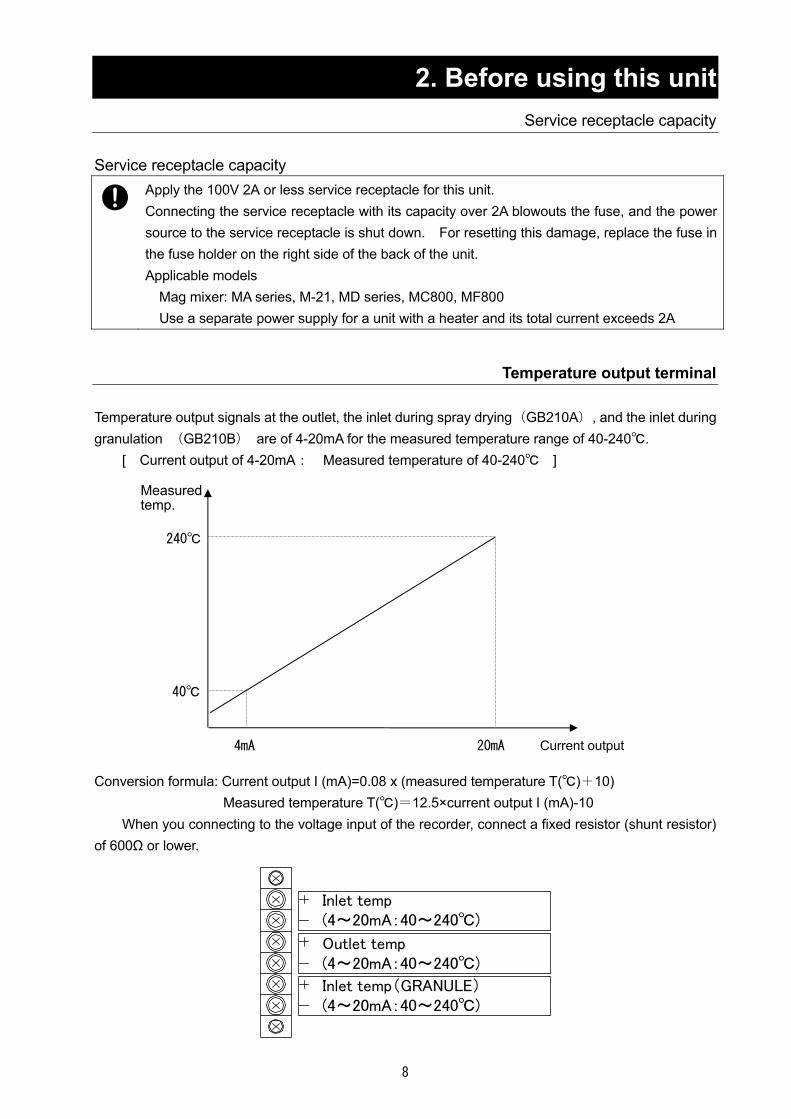
Temperature output terminal Temperature output signals at the outlet, the inlet during spray drying(GB210A), and the inlet during granulation (GB210B) are of 4-20mA for the measured temperature range of 40-240. [ Current output of 4-20mA: Measured temperature of 40-240 ] Conversion formula: Current output I (mA)=0.08 x (measured temperature T()+10) Measured temperature T()=12.5×current output I (mA)-10 When you connecting to the voltage input of the recorder, connect a fixed resistor (shunt resistor) of 600Ω or lower.
Inlet temp(4~20mA:40~240)
Inlet temp(GRANULE)(4~20mA:40~240)
Outlet temp(4~20mA:40~240)
20mA 4mA
40
240
Measured temp.
Current output

9
3.Names of parts and their function Specifications of GB 210B (GB210 + GF200)
Front side
Rear side
Operation panel
Specimen table
Specimen sending pump
Fluid bed chamber
Spray nozzle
Filter chamber
Outlet temperature sensor
Stage
For blind plate for recorder (optional)
Blower (inside the door)
Suction hose
Interim pipe
For GAS410 (optional)
ELB with over current protector
Power cord Exhaust port
Cap
Fuse for service outlet
For connecting GAS410 (Optional)
Temperature output terminal
Connector for GAS410 (optional)
Service outlet AC100V 2A
Cooling water nozzle port O.D.:φ10.5
Pressurized air inletO.D.:φ7
Sensor BOX
Mag mixer setting space
Air spray tube

10
3.Names of parts and their function Specifications of GB 210A (GB210 + GF300)
Front side
Rear side
Specimen
Specimen sending pump
Spray nozzle
Air spray tube
Drying chamber
Outlet temperature sensor
Stage
Cyclone
Product collecting container
Suction hose
Service outlet AC100V 2A
Pressurized air inletO.D.:φ7
ELB with over current protector
Power cord Exhaust port
Temperature outputterminal
For GAS410 (optional)
Connector for GAS410 (optional)
For connecting GAS410 (Optional)
Fuse for service outlet
Cooling water nozzle port O.D.:φ10.5
Cap
Blower (inside the door)
For blind plate for recorder (optional)
Sensor BOX
Container pedest
Mag mixer setting space

11
3.Names of parts and their functions Operation panel
No. Name Operation/action ① Power switch This is used to turn power ON/OFF. ② Lift switch This is used to move UP/DOWN of the stage when an attachment is
installed. This will automatically stop when it is subject to a certain amount of force.
③ Blower control dial This is used to set an air amount. ④ Wind amount display This displays an air amount. ⑤ Key panel
(Touch panel) This is used to perform the operations below and display.
Blower ON/OFF, liquid pump FORWARD/REVERSE Heater ON/OFF, pulse jet switch Stirrer (stirring motor) On/OFF, error indication
⑥ Control selector switch This is used to control temperature on the temperature controller on the selected side while this unit is being operated in specifications of the Mini Spray GB210A.
⑦ Setting and display of outlet temperature
This is used to display an outlet temperature. This is used to display and make settings in the GB210A specifications.
⑧ Display lamp This is used to indicate the specification with which the suction filter installation status complies. GRANULE on:GB210B specification(Mini Bed specification) SPRAY DRY on:GB210A specification(Mini Spray specification)
⑨ Setting and display of mini spray inlet temperature
This is used to display the inlet settings and temperature when the mini spray is used.
⑩ Setting and display of mini bed inlet temperature
This is used to display the inlet settings and temperature when the mini bed is used.
⑪ Pressure meter This meter indicates the pressure of pressurized air. ⑫ Needle valve control dial This dial is used to control pressure of pressurized air. ⑬ Liquid sending speed
control dial This dial is used to control flow of the liquid pump.
①
②
④
⑦
⑩
③
⑬
⑤
⑨⑪
⑫
⑧
⑥

12
4. Operating procedures Preparations
(1) Selecting the power supply(GB210A/GB210B)
First switch the power supply terminal
First check that the switches of the control assembly and the ELB are OFF and then connect the power cord securely to the power supply meeting the specified voltage and current. Ordinary, the unit has been specified to AC200V. Switch the terminals in the unit before connecting the power supply when you are going to use the unit in an AC220V or AC240V district. The terminal block is located inside the door at the right side. Refer P.13 “Exploded view of the suction port”
(2) Connecting an earth(GB210A/GB210B)
The power cord of this unit is an earthed 3-core captire cable (VCT) that integrates an earth wire and you must earth the green wire.
電圧側 黒
電圧側 白
接地極
屋内配線 機器
緑
(3) Connection of the exhaust duct(GB210A/GB210B)
In an environment where hot air or fine particles from the blower are of concern, connect the included exhaust duct to the exhaust port and use a draft chamber to exhaust them to outside.
(4) Adjusting the sensor BOX position (GB210A/GB210B) Because the GB210B spray nozzle has a nozzle fixing clamp, position of the sensor BOX shall be adjusted. Loosen the knurled screws at two positions and fix the sensor BOX so that it touches the spray nozzle.
Drawing of the installed GB210B spray nozzle Drawing of the installed GB210A spray nozzle
Knurled screw
Sensor BOX
Spray nozzle Spray nozzle
Nozzle fixing
Voltage side
Voltage side
Ground side
Black
White
Green
Unit In-house

13
4. Operating procedures Preparations
(5)Connect the nipple (φ7) at the rear of the upper frame and the compressor or other pressurized
air units with the included pressure-proof hose and then securely tighten it using a hose band. Adjust the discharge pressure of the compressor to be constant (0.3MPa or less) using the pressure reducing valve.
(6)Cooling the spray nozzle(GB210A)
The cooling mechanism for the spray nozzle is pre-installed (nozzle O.D.:φ10.5). When you operate the unit under operating conditions under which the spray nozzle is likely to clog, connect a separate cooling water circulating unit (such as CF300) or to a tap water faucet to allow cooking water circulating.
Installation procedures of GB210B(GB210 main body + GF200 mini bed)
(1)Remove four screws, open the right side door and check or switch the suction port connection point on the main body.
Make sure that the GRANULE lamp comes ON when you turn the POWER switch ON. (2)Unpack the mini bed attachment (GF200) and check for any broken glasses or missing parts.
Compressor connecting nipple
Not used Optional for GAS410
Nozzle IN
Nozzle OUT
端子台
Exploded view of the suction port
Drawing of installation ofthe suction port Source voltage selector terminal
Clamp
O ringFilter case
Filter
Filter cover
Clamp
Blind
O ring
Terminal block
Knurled screw

14
4. Operating procedures Preparations
(3) Install parts following the procedures in the order of their numbers.
(4) Turn the POWER switch ON and raise the stage with UP of the lift switch. Stop moving the stage
once when the upper part of the flow layer chamber is close to the flange of the filter chamber, and then turn the UP switch ON intermittently until the top flange of the flow layer chamber is aligned with the packing and the flange of the filter chamber and the stage is stopped.
(5) Install the temperature sensor to the pipe of the interim pipe and insert the plug into the socket on the side of the main body.
(6) Install the suction hose to the pipe of the interim pipe and the pipe at the left front of the stage and fix them with hose clips.
温度センサ取付用ソケット
吸気ホース接続口
2. Installing the pipe
Fix this to an appropriate position with a knurled screw.
Nozzle fixing clamp
Install the interim pipe at three positions with M6 x 30 hex bolts (with flat washers and spring washer).Top surface of interim pipe: with O ring P16 Groove on bottom surface of interim pipe: with O ring P135 Upper inside of interim pipe: with O ring P30
1. Installing the interim pipe
3. Inserting the nozzle
2. Installing the pipeInsert the pipe into the interim pipe and twist itto the internal thread until it completely stops.Take care for top and bottom directions.
4. Installing the filter chamber
Insert the nozzle from the insert hole at the top of the body.
Put the filter from under the filterchamber through the pipe and push itagainst the bottom surface of the interimpipe. Screw it into the bottom end of thefilter retainer nut pipe, and push it up sothat the filter contacts with the interimpipe without any gaps.
Hold the chamber with its stepped flange up, install an O ring to the stepped part, hook the butterfly nut on the interim pipe to the groove on the flange to fix.
5. Installing the filter
6. Installing the flow layer chamberMake sure that on O ring is set in the stage, andset the chamber so that two pins are aligned withthe grooves correctly. The cap will be the nearside.
O ring P145
Flange
O ring P30 (installed inside)
Filter retainer nut
Silicon packing (t5mm)
Cap
Temperature sensor socket
Suction hose connection port
15
4. Operating procedures Preparations
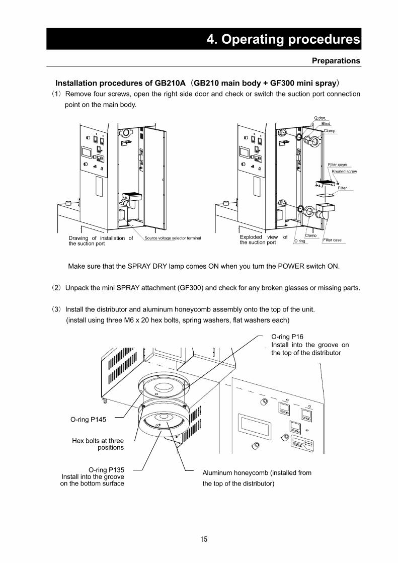
Installation procedures of GB210A(GB210 main body + GF300 mini spray)
(1)Remove four screws, open the right side door and check or switch the suction port connection point on the main body.
Make sure that the SPRAY DRY lamp comes ON when you turn the POWER switch ON.
(2)Unpack the mini SPRAY attachment (GF300) and check for any broken glasses or missing parts. (3)Install the distributor and aluminum honeycomb assembly onto the top of the unit.
(install using three M6 x 20 hex bolts, spring washers, flat washers each)
O-ring P145
O-ring P135 Install into the groove on the bottom surface
Hex bolts at three positions
Aluminum honeycomb (installed from the top of the distributor)
O-ring P16 Install into the groove on the top of the distributor
Exploded view of the suction port
Drawing of installation ofthe suction port
Source voltage selector terminal
Clamp
O ring
Filter case
Filter
Filter cover
Clamp
Blind
O ring
Knurled screw

16
4. Operating procedures Preparations
(4)Insert the pipe in the center of the distributor and twist it all the way.
(5)Install the container stand to the upper row of four taps at the front of the main unit with knurled
screws.
(6)Install the drying chamber taking care to align the groove with the stage positioning pin.
Turn the POWER switch ON, raise the stage the stage with UP of the lift switch while holding the driving chamber with hand. Stop moving the stage once when the upper part of the drying layer chamber is close to the flange of the distributor, and then keep pushing the stage while turning the UP switch ON and OFF until the stage is stopped.
(7) Install the outlet temperature sensor into the pipe at the glass container connecting port and insert the plug into the socket on the side of the main unit.
O-ring P110
Temperature sensor connection
Drying chamber
Container pedestal
Stage positioning pin

17
4. Operating procedures Preparations
(8)Connect the cyclone following the step numbers below.
Cap
2. Connection of the teflon hose and the connecting ferrule D Hose clips at two positions
Connecting ferrule D
1. Connecting the cyclone and the glass chamber
Power clamp 40A Packing 40A
4. Connecting the cyclone and the product collecting container
Product collecting container Container holding band
3. Connecting the cyclone and the connecting ferrule
Power clamp 50A Packing 50A
O-ring P100Put tightly inside the cover

18
4. Operating procedures Operating method
(1) Turn the ELB on the right side of the main unit ON.
(2) Turn the power switch on the operation panel of the main unit ON. Temperature controllers, indication lamps, and the key panel will be displayed.
(3) Check that the specifications correct for the application of this product are set on the display lamp.
※ To change the specifications, follow the installation procedures previously described (P.13 and P.15) to change the settings of the unit.

19
4. Operating procedures Operating method of GB210B
Operating method of GB210B(GB210 main unit + GF200 mini bed)
Granulation method Refer to sample settings for an example case for the standard sample.
Sintered alumina (W.A. ♯180) NET 300g PVA(Polyvinyl alcohol)♯500 NET 50g Solid component density 5wt%
(1)The temperature controller at the upper left part of the operation panel is used as the display and setting device for inlet temperature and the lower temperature controller, as the display for outlet temperature.
SWITCHING is not used when the mini bed is used.
(2) Preliminary heating and setting of samples are performed here.
(2)-1) Install mini bed attachments following the above procedures. Adjust the spray nozzle so that its tip will protrude below by about 30mm from the end of the pipe.
Set spray pressure to 0.01MPa.
(2)-2) Turn the blower switch in the key panel ON. (2)-3) Adjust the left volume so that an appropriate air
amount is obtained while monitoring it on the air amount monitor.
Example Air amount: approx.0.4m3/min

20
4. Operating procedures Operating method of GB210B
(2)-4) Set the inlet temperature. Then turn the heater switch ON to start heating.
Example Inlet temperature setting: 120
(2)-5) When outlet temperature has become stable, turn the
heater switch and the blower switch by performing procedures in (2)-2)、(2)-4) in the reversed order. Example Outlet temperature: Stable at approx. 60
(2)-6)Turn the lift switch DOWN, remove the flow layer chamber, and put sample evenly on the micro pore plate.
※Be sure to wear heat resistant gloves when handling the flow layer chamber, which may be very hot. Example Sample: sintered alumina 300g
(2)-7) Set the flow layer chamber to the main unit again following the installation procedures in (3)-6), (4)on P.14 above.
(2)-8) Setting the liquid sending tube Set the liquid sending tube as shown in the left diagram and then secure the tube, which is made flat with the pump bracket, with a knurled screw.
※When any sample is not sprayed any more, which may indicate clogging of the spray nozzle orifice, push the plunger at the upper part of the nozzle (P33. “Cleaning After Using” Exploded view of the spray nozzle). The needle (P33. “Cleaning After Using” Exploded view of the spray nozzle) will push out the foreign object in the orifice.
(2)-9) Place the liquid sending tube in a container that
contains binder, turn the pump FWD switch ON, and when the binder is close to the nozzle inlet, turn the pump FWD switch OFF. At this time, adjust the liquid sending speed of the pump to an appropriate setting.
Example Binder:polyvinyl alcohol 50g (Actually used amount is approx. 20g) Adjust the liquid sending speed to 12mL/min.
Pump bracket
Plunger

21
Too much attachment of fine powder on the filter may decrease air amount. Press the pulse jet switch on the key panel to blow pressurized air into the filter to remove fine powder off. Press the pulse jet switch at a regular interval to minimize attachment of fine powder onto the filter.
4. Operating procedures Operating method of GB210B
Types and features of binders(reference material)
Types Features Gelatin This has only a weak binding force at a lower concentration and high
concentration solution shall be sprayed with humidification. Dextrin This has only a weak binding force but is superior in molding capability
into tablets. Potato starch This is superior in granule property and inexpensive. Utilized in medical
and food fields. Sodium alginate This has a high viscosity and is suitable as a binder mainly used in the
food field. Gum Arabic Shall be humidified for spraying. This requires a lot of binder. CMC (Sodium Carboxymethyl Cellulose)
This presents a higher viscosity at a lower temperature. This tends to leave considerable powder residues.
HPC(Hydroxypropylcellulose) This is suitable for cohesive, hydrophilic materials. MC(Methyl Cellulose) This has a strong binding force and is suitable to those used for
granules coarser. PVA(Polyvinyl alcohol) This is superior in granulation efficiency but has some shortcomings in
degradation of granulated substances. PVP(Polyvinylpyrrolidone) Those with a higher molecular weight have a strong binding force and
are appropriate for hydrophilic materials.
(3) Follow the same procedures as for the preheating to start operation of the blower and the heater and start flowing sample. Adjust air amount with the blower adjusting dial so that the height of the flow layer coincides with the silicon cap position on the flow layer chamber.
(4) When the outlet temperature has stabilized, set a spray pressure and turn the pump FWD switch ON.
Example Spray pressure 0.04MPa Liquid sending speed:
12mL/min When flow of sample slows down, turn the pump FWD switch OFF to reduce spray pressure to minimum. (Completely shutting spray pressure may cause clogging of the nozzle.) To prevent the nozzle from clogging, use the pump REV switch to return binder to a point close the tube connection port on the nozzle. The pump REV switch is active while it is pressed. Example Turn the pump switch OFF about 30 seconds after
starting spraying. Reduce spray pressure to 0.01MPa.
~Operational hint~
開

22
4. Operating procedures Operating method of GB210
(5) Repeat spraying and drying operations in step (4) until granule diameter you want is obtained. Granule diameter will become gradually larger in the second session of spraying and drying and after, and thus you need to gradually shorten time of binder spraying and gradually increase air amount.
Example Repeat spraying and drying of polyvinyl alcohol
five times.(Approx. 20g is used in total) 《Useful functions》
The pump can be operated in the auto mode only when conditions for spraying and drying time can be quantified in operations of (4) and (5).
Operating procedures a) Press the PUMP AUTO switch. b) Set pump FWD operation time and pump OFF time.
Touching the Time Set key will display a numeric keypad. Enter numeric values and press “ENT” to determine the entered time. Time can be set in the range of 1-600 seconds and when you enter a numeric value outside this range and press “ENT”, it will be changed to the upper or lower limit automatically.
c) Start automatic operation of the pump using the PUMP AUTO switch.
d) To stop automatic operation, press the PUMP AUTO switch and then the ESC switch.
When flow of samples has degraded, either increase blower air amount or press the stirrer switch in order to disperse the samples evenly to always keep good flow conditions. And when the spraying is unstable, press the upper tip of the nozzle to remove clogging at the nozzle tip. The stirrer switch is active while it is pressed. Press the switch for three seconds or more if you want to operate continuously. Press it again to cancel continuously operation. The stirrer will also stop when the blower is turned OFF.
~Operational hint~

23
4. Operating procedures Operating method of GB210
(6) When the sample reaches the granule diameter you want, sufficiently dry the samples, and turn the heater OFF.
When outlet temperature has decreased to 45 or lower, turn the blower OFF and choke spray pressure to 0.
※To avoid a malfunction of the unit, do not turn the blower OFF while the outlet temperature is 45 or more.
(7) Using the pulse jet switch, remove foreign objects off the filter.
(8) Lower the stage with the lift DOWN switch and then turn the POWER switch OFF.
Take out the flow layer chamber and collect the granulated samples.
(9) Wash the containers according to the maintenance method (P33 and following pages “Cleaning After Using”).
Close

24
4. Operating procedures Operating method of GB210B
Drying operation of moist powder ※Drying operation of moist powder does not use the liquid sending pump and spray pressure. (1) Put sample evenly on the micro pore plate in the flow layer chamber and set the chamber to the
main unit following the installation procedures in (3)-6),(4) on P.14 above. (2) Referring to procedures for granulating operation, set the nozzle ((2)-1), operate the blower
((2)-2), adjust air amount ((2)-3), operate the heater ((2)-4), and perform drying operation of samples. Adjust air amount with the blower adjusting dial so that the height of the flow layer coincides with the cap position on the flow layer chamber.
(3) The outlet temperature decreases once drying of sample is started and resume increasing when
water content in the sample become less. Drying finishes when flow status of sample improves and increase of outlet temperature almost saturates.
Follow procedures in (6)~(8) for granulation operation to stop operation and take out the sample out of the flow layer chamber.
(4) Wash the containers, the spray nozzle, and filters according to (P33 and following pages “6. Maintenance method”) after using the unit.
Too much attachment of fine powder on the filter may decrease air amount. Press the pulse jet switch on the key panel to blow pressurized air into the filter to remove fine powder off. Press the pulse jet switch at a regular interval to minimize attachment of fine powder onto the filter. When flow of samples has degraded, either increase blower air amount or press the stirrer switch on the key panel in order to disperse the samples evenly to always keep good flow conditions.
~Operational hint~

25
4. Operating procedures Operating method of GB210B
Operating method of GB210A(GB210 main unit + GF300 spray attachment) Spray drying operation method Refer to sample settings for an example case for the standard sample.
Sodium chloride solution NET 100g Solid component concentration 5wt%
(1)The temperature controller at the upper right part of the operation panel is used as the display and setting device for inlet temperature and the lower temperature controller, as the same device for outlet temperature. The temperature controller at the upper left part is not used. You select temperature control for inlet or outlet temperature using SWITCHING. When you want to control temperature by the outlet temperature, select inlet temperature at the start of operation switch to outlet temperature once the temperature has stabilized. Example: Select the inlet side with SWITCHING
Inlet temperature setting: 150
(2)Install the mini spray attachment following the procedures above (P.15~P.17).
(3)Turn the blower switch ON and set air amount.
Example: Air amount 0.45m3/min
(4)Turn the heater switch ON.

26
4. Operating procedures Operating method of GB210B
(4)Set the liquid tube as shown in the left diagram and fix the tube with flattened with the pump bracket. Set distilled water as the specimen.
Example: Specimen of distilled water set
* When specimen is not sprayed any more, it is
suspected that the orifice of the spray nozzle is clogged, which can be cleared by pressing the plunger at the upper part of the nozzle (P33." Cleaning After Using “Exploded view of the spray nozzle). The needle (P33. "Cleaning After Using “Exploded view of the spray nozzle) pushes out the clog in the orifice.
(5)When the inlet and the outlet temperatures have reached the temperatures you want, set the spray pressure, turn the pump FWD switch ON and send distilled water.
Example: Set the spray pressure to 0.1MPa when the
outlet temperature has risen to around 80. Adjust liquid sending speed so that the outlet temperature will be slightly lower than about 75.
(6)Readjust dry air amount, spray pressure, and liquid
sending speed so that the inlet and the outlet temperature will be stable at the temperatures you want.
Example: Adjust liquid sending speed so that the outlet
temperature will be stable at around 75 or slightly lower temperature.
Pump bracket
・Influences below are of specific settings on the outlet
temperature when the inlet temperature is constant. Sent specimen liquid amount
→small :outlet temperature →high Dry air amount
→large :outlet temperature →high Specimen density (external factor)
→high :outlet temperature→high ・Drops of sprayed liquid will become fine at a higher
spray pressure.
~Operational hint ~
Open
Plunger
27
4. Operating procedures Operating method of GB21
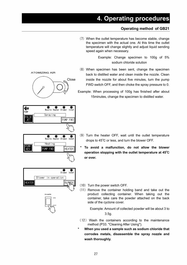
(7)When the outlet temperature has become stable, change the specimen with the actual one. At this time the outlet temperature will change slightly and adjust liquid sending speed again when necessary.
Example: Change specimen to 100g of 5%
sodium chloride solution
(8)When specimen has been sent, change the specimen back to distilled water and clean inside the nozzle. Clean inside the nozzle for about five minutes, turn the pump FWD switch OFF, and then choke the spray pressure to 0.
Example: When processing of 100g has finished after about
15minutes, change the specimen to distilled water.
(9)Turn the heater OFF, wait until the outlet temperature drops to 45 or less, and turn the blower OFF.
* To avoid a malfunction, do not allow the blower
operation stopping with the outlet temperature at 45 or over.
(10)Turn the power switch OFF. (11)Remove the container holding band and take out the
product collecting container. When taking out the container, take care the powder attached on the back side of the cyclone cover.
Example: Amount of collected powder will be about 3 to
3.5g.
(12)Wash the containers according to the maintenance method (P33. "Cleaning After Using").
* When you used a sample such as sodium chloride that corrodes metals, disassemble the spray nozzle and wash thoroughly.
Close

28
4. Operating procedures Operating method of GB210A/GB210B
KEY PANEL Description of indication lamps You can confirm the operating statuses of switches one the KEY PANEL by checking whether a specific lamp is on or off. Each lamp will be turned on at the upper right corner on the KEY PANEL.
Lamp on: Indicates that the spray nozzle is attached. Lamp blink: Indicates that a spray nozzle is not attached.
You can control temperature by setting a temperature on the outlet side temperature controller while the lamp is on. *The lamp is on only when GB210A specifications is used.
You can control temperature by setting a temperature on the inlet side temperature controller while the lamp is on. *The lamp is on only when GB210A specifications is used.
When the lamp is on, the blower is in operation.
When the lamp is on, the blower is in operation.
When the lamp is on, the liquid sending pump is operating in the normal direction.
When the lamp is on, the liquid sending pump is operating in the normal direction.
When you want to stop processing of a sample or the nozzle is clogged Stop sending liquid with the following operations in “Operation method of GB210B".
If you want to process another sample, collect contents in the product container, clean it following
the maintenance procedures (P33 and following pages “6. Maintenance method”), and then operate the unit with another sample.
PUMP REV
FWD PUMP
Heate
Blowe
Outlet
Nozzle
Granulation procedures(6)~(9)
Stop processing of samples
Granulation procedures(6)~(9)
Spray drying operation(8)~(12)
Granulation operation
Drying of moist powder
Spray drying operation

29
5. Handling Precautions
Warning 1. Substances that cannot be used
Never use an explosive, a flammable, or a substance that contains them. Otherwise, an explosion or a fire may result. GB210A supports organic solvents by connecting it to the optional GAS410. Carefully read the operation manual of GAS410 and take special care for handling of organic solvents. See P.56 "15. List of Dangerous Substances ".
2. If a problem occurs
f smoke or strange odor should come out of this unit for some reason, turn off the power key right away, and then turn off the circuit breaker and the main power. Immediately contact a service technician for inspection. If this procedure is not followed, fire or electrical shock may result. Never perform repair work yourself, since it is dangerous and not recommended.
3. Do not touch the part with high temperature
The chamber, cyclone, and peripheral part become high temperature during and just after operation. Do not touch these parts, for there may be caused heat injury.
Caution 1. Do not put anything on this unit
Do not put anything on this unit. It will cause injury if fall.
2. During a thunder storm
During a thunderstorm, turn off the power key immediately, then turn off the circuit breaker and the main power. If this procedure is not followed, fire or electrical shock may be caused.
3. Recovering after power failure
When the unit stopped due to a power outage during operation and power was supplied again, the unit resumes operation at the status immediately before the outage.
4. After installing
It may cause injure to a person if this unit falls down or moves by the earthquake and the impact, etc.. To prevent, take measures that the unit cannot fall down.

30
5. Handling Precautions Drying Method under Appropriate Condition
Items for GB210A (1) The best appropriate drying condition is differed depending on the sample to be dried. Inquire
the data for the partial example of various samples. (2) Adjust the drying condition so as to match to the various errors to be possible to occur such as
too much adhesion of the sample to the drying chamber, too high density of the sample, too low temperature around inlet, too high or too low pressure of spray air, too much feeding amount of sample.
(3) When the spray direction is changed by the adhesion of the sample to the spray nozzle during operation, turn "ON" the pulse jet switch, and blowout the adhesive from the tip of the nozzle using pressurizing air. Even thought the adhesive is not blowout, dismount the spray nozzle, and clean the tip of the nozzle using the soaked paper in water.
(4) The possible cause for adhesion of the sample to the cyclone part is either not evaporating the solvent (distilled water or ion-exchanged water) with enough or the property of the sample itself (low melting point, absorption, etc.)。
For depleting the powder, increasing the amount of heat for sample is the best measure. Therefore, perform either measure below, to increase either temperature around inlet or flow rate of the drying air, or to reduce the feeding amount of the sample, that is, to reduce the difference between the temperature around inlet and that around outlet. When the reason is in the property of the sample itself, adjust the sample by adding the special additive, etc. (5) In the case that the hygroscopicity is high, the product may become the moist powder in the container. Change the drying condition following the method in (4), or, if required, heat up the container for product before operation.
(6) The orifice of the spray nozzle is 460μ. If the sample is blocked with suspension at orifice part impetuously, use the 508μ and 711μ nozzles prepared for the orifice as optional (Nozzle main body P33." Cleaning After Using ",the nozzle main body, the needle, and the ring in the exploded view of the spray nozzle are common with the 406μ nozzle)These 508μ and 711μ nozzles are differed on the point of the size of the spray pattern and particle diameter of the drop slightly compared to the 406μ one, and these differences may affect the interference status. Refer to the Graph 1 for the relation between spray air pressure and spray airflow rate (atmospheric conversion). グラフ.1
(7) The too small powder (few μ or less) among dried ones is impossible to be collected, and exhausted to the outside through the blower. If this exhausted amount of the too small powder becomes more, decrease either spray airflow rate or spray air pressure. Also, since the particle diameter becomes smaller as the density of the sample is lower, adjust the density of the sample if required.
Spra
y ai
rflow
rate
(atm
osph
eric
con
vers
ion)
.
Spray air pressure
31
5. Handling Precautions Drying Method under Appropriate Condition
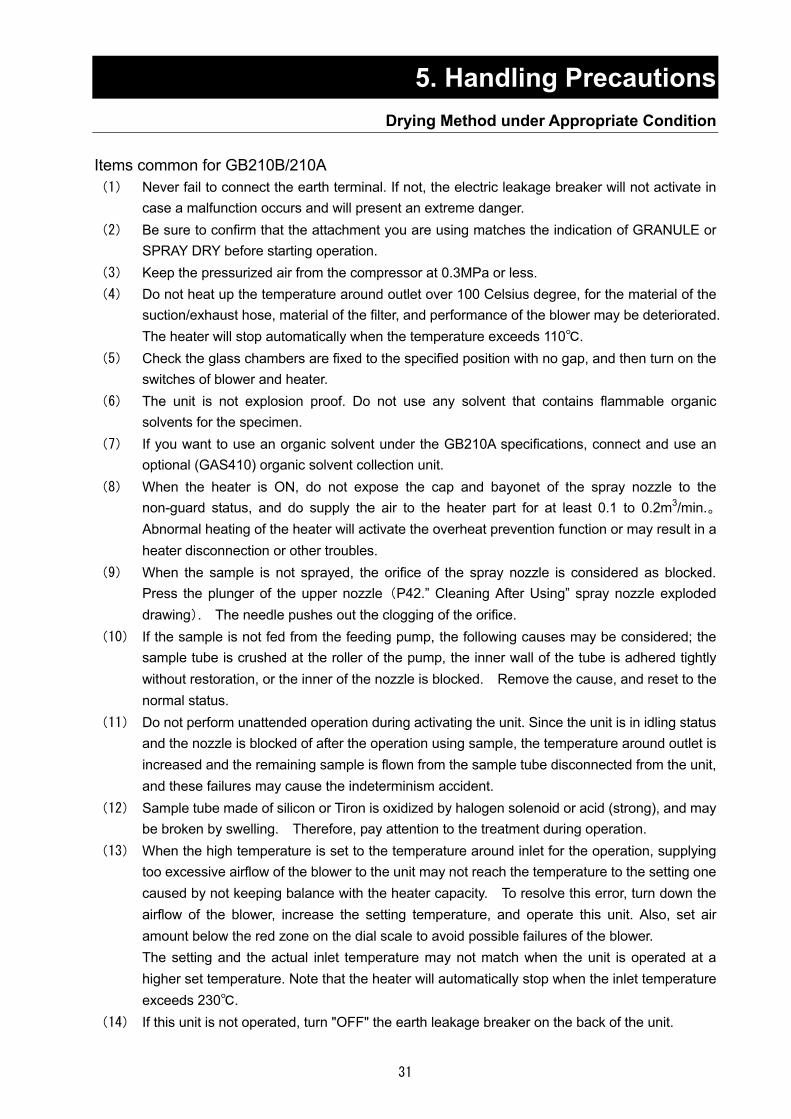
Items common for GB210B/210A (1) Never fail to connect the earth terminal. If not, the electric leakage breaker will not activate in
case a malfunction occurs and will present an extreme danger. (2) Be sure to confirm that the attachment you are using matches the indication of GRANULE or
SPRAY DRY before starting operation. (3) Keep the pressurized air from the compressor at 0.3MPa or less. (4) Do not heat up the temperature around outlet over 100 Celsius degree, for the material of the
suction/exhaust hose, material of the filter, and performance of the blower may be deteriorated. The heater will stop automatically when the temperature exceeds 110.
(5) Check the glass chambers are fixed to the specified position with no gap, and then turn on the switches of blower and heater.
(6) The unit is not explosion proof. Do not use any solvent that contains flammable organic solvents for the specimen.
(7) If you want to use an organic solvent under the GB210A specifications, connect and use an optional (GAS410) organic solvent collection unit.
(8) When the heater is ON, do not expose the cap and bayonet of the spray nozzle to the non-guard status, and do supply the air to the heater part for at least 0.1 to 0.2m3/min.。Abnormal heating of the heater will activate the overheat prevention function or may result in a heater disconnection or other troubles.
(9) When the sample is not sprayed, the orifice of the spray nozzle is considered as blocked. Press the plunger of the upper nozzle (P42.” Cleaning After Using” spray nozzle exploded drawing). The needle pushes out the clogging of the orifice.
(10) If the sample is not fed from the feeding pump, the following causes may be considered; the sample tube is crushed at the roller of the pump, the inner wall of the tube is adhered tightly without restoration, or the inner of the nozzle is blocked. Remove the cause, and reset to the normal status.
(11) Do not perform unattended operation during activating the unit. Since the unit is in idling status and the nozzle is blocked of after the operation using sample, the temperature around outlet is increased and the remaining sample is flown from the sample tube disconnected from the unit, and these failures may cause the indeterminism accident.
(12) Sample tube made of silicon or Tiron is oxidized by halogen solenoid or acid (strong), and may be broken by swelling. Therefore, pay attention to the treatment during operation.
(13) When the high temperature is set to the temperature around inlet for the operation, supplying too excessive airflow of the blower to the unit may not reach the temperature to the setting one caused by not keeping balance with the heater capacity. To resolve this error, turn down the airflow of the blower, increase the setting temperature, and operate this unit. Also, set air amount below the red zone on the dial scale to avoid possible failures of the blower. The setting and the actual inlet temperature may not match when the unit is operated at a higher set temperature. Note that the heater will automatically stop when the inlet temperature exceeds 230.
(14) If this unit is not operated, turn "OFF" the earth leakage breaker on the back of the unit.

32
5. Handling Precautions For GB210B (1) At a large air amount, the effect of the pulse jet will be compromised and the amount of powder
attaches onto the filter will increase. If you need to remove it, lower the air amount once before using pulse jet.
(2) When amount of foreign objects is large at the upper part of the filter chamber and the flow layer chamber, simply tap them lightly to remove them. If those objects are stubborn, remove the cap of the flow layer chamber as necessary and remove them using a spatula.
(3) When amount of powder or most powder put in the chamber is large, the stirrer blades may not rotate even when you turn the stirrer switch ON. In that case, to avoid a malfunction of the motor from over load, do not use the stirrer switch but stir inside the chamber using a spatula as in (2).
(4) After having sent binder, binder remained in the nozzle may drip after the pump has been stopped. Using the pump REV switch, return binder to the connection port of the liquid sending tube. Note, in this case, that the tube may come off if you return binder at a high speed of the pump.
For GB210A (1) If the leakage is existed between container for product and bracket at lower of the cyclone, the
dried powder may be stocked onto the lower of the cyclone without falling into the container for product. Therefore, pay special attention to the unit with the container for product be mounted.
(2) When the specimen accumulated on the nozzle tip in an ice pillar-like form, clean it off using the pulse jet switch on the touch panel.
(3) Since the capacity of the container for product is approx. 750ml, the normal powder can fulfill almost 80% of the container by processing 200 to 250g amounts. If continuing operation more, the collecting efficiency of the powder deteriorates excessively. Stop operation for a while, and take the collected powder out of the container.
(4) Depending on the sample to be processed, the static electricity may be occurred at cyclone. Therefore, remove the static electricity with the appropriate method. It is efficient that the wire is wounded to the glass portion for grounding, but it is more convenient to use the static electricity remover by setting against the cyclone vertically.
(5) The cyclone may charge easily with static electricity depending on the specific specimen used, or operating environment or conditions. Implement countermeasures against static electricity such as attaching included earth clips at three positions on the clamp at the connection of the cyclone or attaching an antistatic brush to the body of the cyclone.

33
6. Maintenance Method Daily Inspection and Maintenance
Warning Disconnect the power cable from the power source when doing an inspection or maintenance
unless needed. Perform the daily inspection and maintenance after returning the temperature of this unit to the
normal one. Do not disassemble this unit.
Caution Use a well-drained soft cloth to wipe dirt on this unit. Do
not use benzene, thinner or cleanser for wiping. Do not scrub this unit. Deformation, deterioration or color change may result in.
ベンジンシンナー
クレンザー
Cleaning After Using (1) After completing the operation, remove the attachments following the process “Preparations " on
P.12 in reverse order. (2) Clean the portion of attachment to which the powder is adhered. (3) Flow the distilled water into the sample tube by pressing the pump switch, and remove the
contaminant attached to the inner of the part. (4) Remove the spray air tube and sample tube from the spray nozzle, and disassemble the nozzle
as shown in the Photo 1. After disassembling, clean it using the supersonic cleaner. Remaining the contaminant to the inner of the part may cause the insufficient spray. Therefore, clean it completely.
Spray nozzle exploded drawing
Nozzle fixing (only for GF 200)
Plunger Needle
Gasket
Main unit of nozzle Nozzle for liquid
Ring
Nozzle for air

34
6. Maintenance Method Daily Inspection and Maintenance
Filter Cleaning Clean up the filter in blower periodically.
1) Open the door at the bottom of the front surface of the unit, and disconnect the hose from the blower.
2) Open the front cover by removing the two fastening plates for the cover from the upper surface of the blower, and open the front cover, and take the filter out.
3) The followings are the cleaning procedures of the filter. ① Wash the filter pressing in the water repeatedly, and air-dry it. ② Compressed air blowing. ③ Vacuum cleaning with a cleaner. ④ Press washing the filter after being immersed into the solvent that hot water (approx. 40
Celsius degree) and neutral detergent are mixed at a rate of 5:95 one whole day and night, then rinse it with water and air-dry it.
4) When assembling, reversely execute the above procedure. Turn the soft surface of the filter to windward when installing the filter.
Suction port filter
A stainless steel mesh plate is used at the suction port filter. Referring to the exploded views of the suction port on P.13 or P.15, disassemble the suction port and clean it using an electric cleaner.
Monthly maintenance Check the earth leakage breaker function.
・ Connect the power cord. ・ Turn the breaker on. ・ Push the red test switch by a ballpoint pen etc. If there
is no problem, the earth leakage breaker will be turned off.
Test button

35
7. Long storage and disposal When not using this unit for long term / When disposing
Caution Warning When not using this unit for long term… Turn off the earth leakage breaker and original
power source for safe without fail. Also, store the glass unit after removing it from the main unit. When the glass unit is contacted to the external, it may cause the breakage.
When disposing… Keep out of reach of children. Remove the power cord.
Matters to consider when disposing of the unit Environmental protection should be considered ・ We request you to disassemble this unit as possible and recycle the reusable parts considering to
the environmental protection. The feature components of this unit and materials used are listed below.
Component Name Material
Parts of Main Unit
Casing Bonderizing steel plate baked with melamine resin coating, Stainless steel
Insulating material Ceramic Felton
Specimen bed, ceiling plate, pipings
Stainless steel
Production plates Polyethylene (PET) resin film
Tube Silicon rubber, teflon
Electrical Parts
Heater Stainless steel and others
Motor Iron, Aluminum, Copper wire and others
Circuit boards Composites with board, condenser, resister and transformer
Power cord & wiring materials and others
Synthetic rubber, resins
Sensor Stainless steel and others
36
8. When a trouble occurs Safety unit and error indications
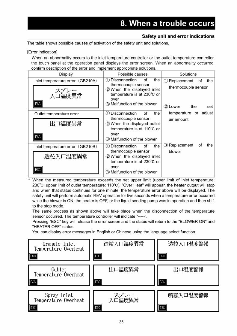
The table shows possible causes of activation of the safety unit and solutions. [Error indication]
When an abnormality occurs to the inlet temperature controller or the outlet temperature controller, the touch panel at the operation panel displays the error screen. When an abnormality occurred, confirm description of the error and implement appropriate solutions.
Display Possible causes Solutions Inlet temperature error(GB210A)
① Disconnection of the thermocouple sensor
② When the displayed inlet temperature is at 230 or over
③ Malfunction of the blower
Outlet temperature error
① Disconnection of the thermocouple sensor
② When the displayed outlet temperature is at 110 or over
③ Malfunction of the blower Inlet temperature error(GB210B)
① Disconnection of the thermocouple sensor
② When the displayed inlet temperature is at 230 or over
③ Malfunction of the blower
① Replacement of the thermocouple sensor
② Lower the set
temperature or adjust air amount.
③ Replacement of the
blower
* When the measured temperature exceeds the set upper limit (upper limit of inlet temperature: 230; upper limit of outlet temperature: 110), "Over Heat" will appear, the heater output will stop and when that status continues for one minute, the temperature error above will be displayed. The safety unit will perform automatic REV operation for five seconds when a temperature error occurred while the blower is ON, the heater is OFF, or the liquid sending pump was in operation and then shift to the stop mode. The same process as shown above will take place when the disconnection of the temperature sensor occurred. The temperature controller will indicate "-----". Pressing "ESC" key will release the error screen and the status will return to the "BLOWER ON" and "HEATER OFF" status. You can display error messages in English or Chinese using the language select function.

37
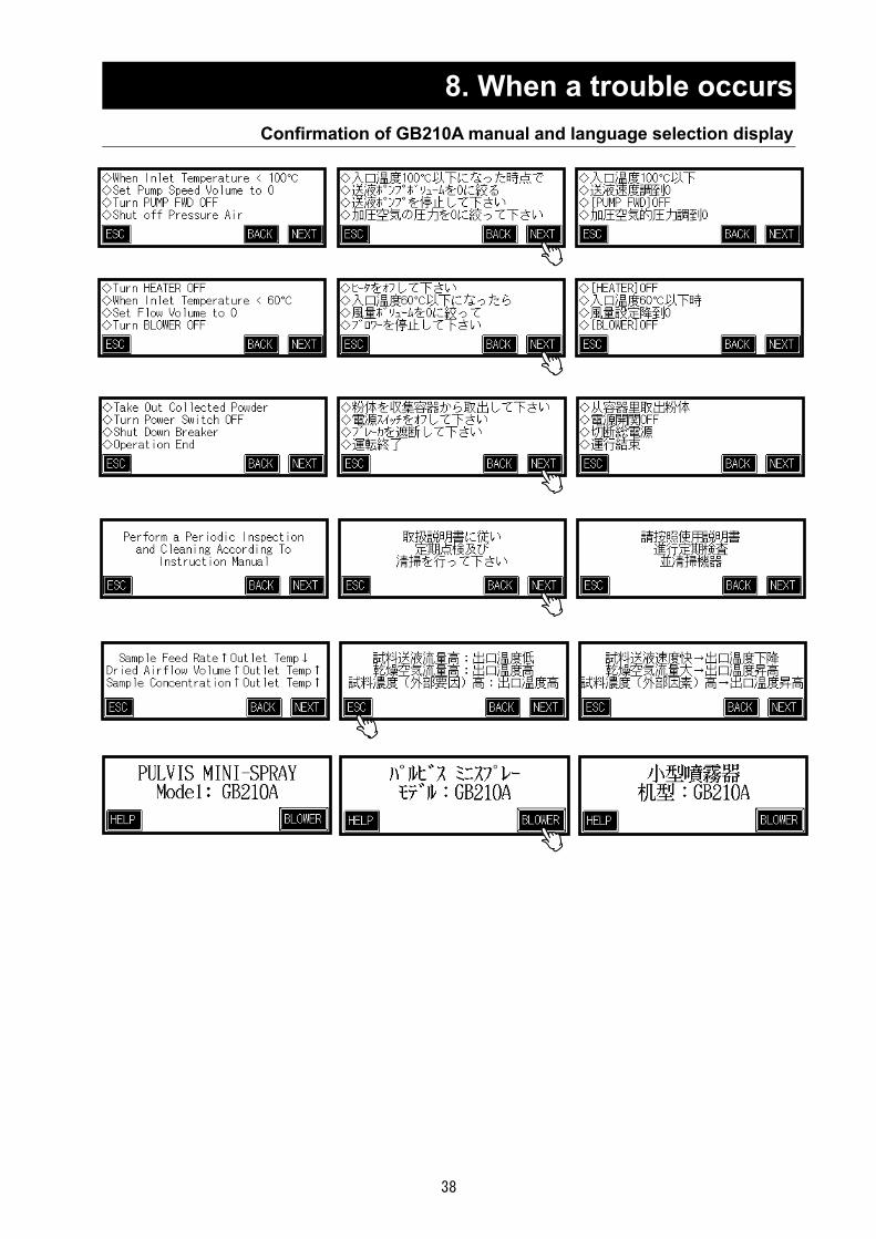
8. When a trouble occurs Confirmation of GB210A manual and language selection display
38
8. When a trouble occurs Confirmation of GB210A manual and language selection display

39
8. When a trouble occurs Confirmation of GB210B manual and language selection display

40
8. When a trouble occurs Confirmation of GB210B manual and language selection display

41
8. In the Event of Failure… Trouble Shooting
Symptoms Possible causes Countermeasures
The POWER does not turn ON.
ELB is turned OFF Malfunction of the power supply The wire ire short-circuited. Malfunction of power switch
Turn the ELB ON Check the power supply circuit Replace the cord Replace the power switch
Blower does not activate.
Incorrect connecting of the connector of blower
Breaking of blower input cord Blower switch failure
Blower motor failure
Blower motor brush failure Blower circuit failure and wiring
failure
Connect correctly.
Replace the cart. Replace the touch panel,
sequencer or thermo regulator. Replace the motor or motor
substrate Replace the brush Maintain or replace the part
Heater does not activate.
Incorrect connecting of the connector of heater
Activated the protection circuit caused by the failure of the other device (displayed error)
Activated the protection circuit without turning on the blower switch
Heater disconnection Heater switch failure
Heater circuit failure and wiring
failure
Connect correctly.
Solve the problem, and turn ON the switch.
Turn ON the blower, and then turn
ON the heater switch. Replace the part. Replace the touch panel or
sequencer Maintain the part or replace the
thermo regulator. Feeding pump does not activate
The indicator of the pump adjusting dial is at "0"
Pump switch failure
Pump motor failure Pump circuit failure and wiring
failure Imperfect nozzle attachment
Adjust the dial.
Replace the touch panel or sequencer
Replace the motor or driver Maintain the part
Check and adjustment of
attachment status of the nozzle Pulse jet does not activate
Failure of pressuring air source
Connecting failure of tube Solenoid valve failure Pulse jet switch failure
Pulse jet circuit failure and wiring
failure
Make arrangement aiming for appropriate status.
Maintain or replace the part. Replace the part. Replace the touch panel or
sequencer Maintain the part
42
8. In the Event of Failure… Trouble Shooting
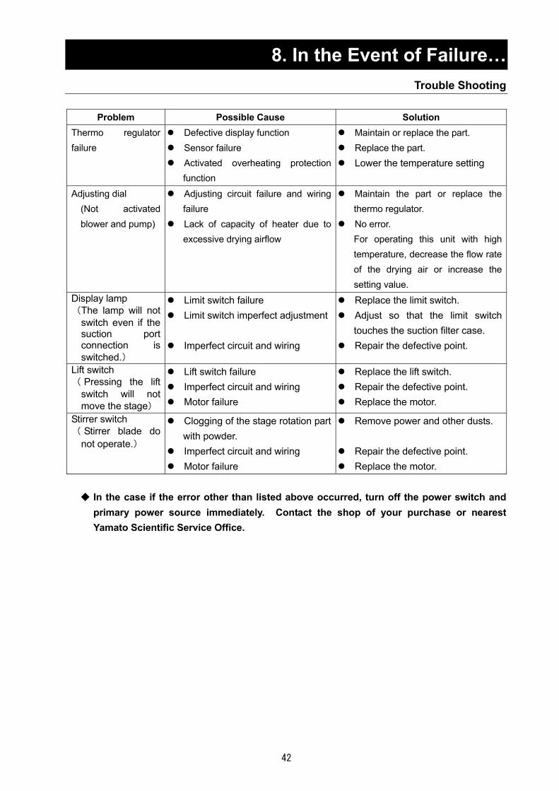
Problem Possible Cause Solution
Thermo regulator failure
Defective display function Sensor failure Activated overheating protection
function
Maintain or replace the part. Replace the part. Lower the temperature setting
Adjusting dial (Not activated blower and pump)
Adjusting circuit failure and wiring failure
Lack of capacity of heater due to excessive drying airflow
Maintain the part or replace the thermo regulator.
No error. For operating this unit with high temperature, decrease the flow rate of the drying air or increase the setting value.
Display lamp (The lamp will not
switch even if the suction port connection is switched.)
Limit switch failure Limit switch imperfect adjustment
Imperfect circuit and wiring
Replace the limit switch. Adjust so that the limit switch
touches the suction filter case. Repair the defective point.
Lift switch ( Pressing the lift
switch will not move the stage)
Lift switch failure Imperfect circuit and wiring Motor failure
Replace the lift switch. Repair the defective point. Replace the motor.
Stirrer switch ( Stirrer blade do
not operate.)
Clogging of the stage rotation part with powder.
Imperfect circuit and wiring Motor failure
Remove power and other dusts.
Repair the defective point. Replace the motor.
In the case if the error other than listed above occurred, turn off the power switch and
primary power source immediately. Contact the shop of your purchase or nearest Yamato Scientific Service Office.

43
9. After Service and Warranty When requesting a repair
When requesting a repair
If any trouble occurs, immediately stop operation, turn the power switch off, pull out the power plug and contact your dealer, our sales office or our customer service center.
Information necessary for requesting a repair Model name of the product Serial number Date (y/m/d) of purchase Description of trouble (as in detail as possible)
Be sure to indicate the warranty card to our service representative.
Warranty card (attached separately) Warranty card is given by your dealer or one of our sales offices and please fill in your dealer,
date of purchase and other information and send it to our customer service center by Facsimile (03-3231-6523). Then, store it securely.
Warranty period is one full year from the date of purchase. Repair service for free is available
according to the conditions written on the warranty card.
For repairs after the warranty period consult your dealer, one of our sales offices or our customer service center.
Paid repair service is available on your request when the product’s functionality can be maintained by repair.
Minimum holding period of repair parts
The minimum holding period of repair parts for this product is seven years after end of production. Repair parts here refer to parts necessary for maintaining performance of the product.
See the warranty card or the nameplate on the unit. See the section “3.Names of parts and their function” on page 9.

44
10. Specification Specifications of main unit
Configuration Basic unit [GB210] +Mini Splay Attachment [GF-300]
Function Splay drying
Sample for drying Solution, Suspension, Emulsion (Flammable organic solvent is
invalid.) GB2
10A
Total weight Approx. 121kg Configuration Basic unit [GB210]〕+mini bed attachment[GF200]
Function Granulation and drying in the flow layer
GB2
10B
Total weight Approx.123kg Thermo regulator PID digital thermo regulator
Heater 2kW~2.88kW
Blower Brushless motor Stirring mechanism Induction motor (Only for GB210B)
Sample feeding pump Proportioning Peli pump Pressure gauge for spray air
Pressure gauge for bourdon tube Measurement range: 0 to 294kPa
Blowout mechanism for pressurizing air Use pulse jet type solenoid valve
Temperature adjustment range INLET:0~220/ OUTLET:0~60
Temperature adjustment accuracy ±1
Temperature display Digital display of the temperature around Inlet/Outlet
(metal-sheathed thermocouple element K) Adjusting range for drying air 0~0.7m3/min
Power supply *1 AC200V single phase 16A(AC220V 17A AC240V 18A) External dimensions *2)(W×D×H)
760×420×1350
Weight Approx. 110kg Specimen tube Silicon I.D.2 ×O.D.4 ×1m Tiron I.D.2 ×O.D.4 ×1m
23
Basi
c un
it〔G
B210
〕
Attached accessories
Outlet temperature sensor Exhaust hose Made of vinyl chloride I.D.:50 ×2m Hose band #64 Container pedestal(Only for GB210A) Sample box Knurled screw Tetlon braded hose 5m Hose clamp Earth wire Warranty card Operation manual
11111412111
※GB210A is for water soluble solvent only. Be sure to connect it to the separate optional GAS410 when you are going to use an organic solvent. Also note that GAS410 cannot be connected to GB210B.
45
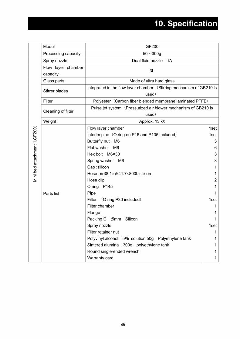
10. Specification
Model GF200
Processing capacity 50~300g
Spray nozzle Dual fluid nozzle 1A Flow layer chamber capacity
3L
Glass parts Made of ultra hard glass
Stirrer blades Integrated in the flow layer chamber (Stirring mechanism of GB210 is
used) Filter Polyester(Carbon fiber blended membrane laminated PTFE)
Cleaning of filter Pulse jet system(Pressurized air blower mechanism of GB210 is
used) Weight Approx. 13
Min
i bed
atta
chm
ent〔
GF2
00〕
Parts list
Flow layer chamber Interim pipe(O ring on P16 and P135 included) Butterfly nut M6 Flat washer M6 Hex bolt M6×30 Spring washer M6 Cap :silicon Hose :φ38.1×φ41.7×800L silicon Hose clip O ring P145 Pipe Filter (O ring P30 included) Filter chamber Flange Packing C t5mm Silicon Spray nozzle Filter retainer nut Polyvinyl alcohol 5% solution 50g Polyethylene tank Sintered alumina 300g polyethylene tank Round single-ended wrench Warranty card
1set1set
3633112
11
1set111
1set11111

46
10. Specification
Model GF300 Amount of water evaporation
Max. Approx. 1300ml/h
Spray nozzle Binary Nozzle 1A Drying chamber Made from super hard glass Cyclone Made from super hard glass Container for product Made from super hard glass Dust removal of nozzle tip
Pulse jet type (used the pressuring air blower mechanism for GB210 model)
Weight Approx. 11
Min
i Spl
ay A
ttach
men
t〔G
F300
〕
Parts list
Cyclone Drying chamber Product collecting container Container holding band Packing 40A, 50A Power clamp 40A, 50A Cap Connecting ferrule (D) PFA wave shaped tube 1-1/2, 3 feet long (for connecting the cyclone) Hose clip Distributor (O-rings P16, P135 included) Hex bolt M6 x 20 Flat washer M6 Spring washer M6 Aluminum honeycomb Pipe Spray nozzle Round single-ended wrench Polyethylene tank for 100g of 5% sodium chloride solution Warranty card
1set 1set
1 1
1each1each
1 1 1 2 1 3 3 3 1 1 1 1 1 1
*1 Including capacity of service receptacle (2A). *2 The outer dimension does not include the projection part. Please remind that this product may be changed the specification and others for revision without any announce to the user.

47
11.Wiring Diagram
In
case
of
di
ffere
ntvo
ltage
, cha
nge
over
the
term
inal
. T1
-5: 2
00V
T1-4
: 220
V T1
-3: 2
40V
Fem
ale
pin
Spra
y Inl
et tem
p. cu
rrent
outpu
t
Atta
ched
cab
le
(300
mm
)
Atta
ched
cab
le
SDA: B
rown
SDB: R
ed RD
A: Oran
ge RD
B: Yello
w SG
: Green
CS
A: Black
CS
B: White
Atta
ched
cab
le At
tach
ed c
able
Atta
ched
cab
le
Outle
t temp
. cur
rent
outpu
t
Gran
ulatio
n Inl
et tem
p. cu
rrent
outpu
t
Fem
ale
pin
Fem
ale
pin
Fem
ale
pin
Out
put
bloc
k

48
12. System Chart System Chart of GB210B
吸気
⑲
①
⑰
④
⑯
⑱②
⑮⑧
③
⑭
⑥
⑨
⑩
⑳⑦
⑤⑬⑫⑪
試料(バインダ)
加圧空気接続
オプション接続用(GAS410)
No Part name No Part name ① Heater ⑪ 3-way solenoid valve ② Micro pore plate ⑫ Needle valve ③ Flow layer chamber ⑬ Pressure meter ④ Filter chamber ⑭ Stirring blade ⑤ Nozzle ⑮ Stirring motor ⑥ Filter ⑯ Inlet temperature sensor ⑦ Liquid sending pump ⑰ Outlet temperature sensor ⑧ Blower ⑱ Blind ⑨ Interim pipe ⑲ Suction port, suction filter
⑩ Solenoid valve ⑳ Nozzle cooling connection port
For connecting optional unit
(GAS410)
Connecting pressurized air
Specimen(Binder)
Air intake

49
12. System Chart System Chart of GB210A
オプション接続用(GAS410)
⑪ ⑫
試料
加圧空気接続
⑬
⑦ ⑳
⑤
C
A⑰
⑩
⑯
⑱
①
吸気
⑲
B
⑮
E
D
⑧
No Part name No Part name ① Heater ⑰ Inlet temperature sensor ⑤ Spray nozzle ⑱ Blind ⑦ Liquid sending pump ⑲ Suction port, suction filter
⑧ Blower ⑳ Nozzle cooling connection port
⑩ Solenoid valve A Drying chamber ⑪ 3-way solenoid valve B Cap ⑫ Needle valve C Distributor ⑬ Pressure meter D Cyclone ⑮ Stirring motor (Not used) E Product collecting container⑯ Inlet temperature sensor
For connecting optional unit
(GAS410)
Connecting pressurized air
Specimen
Air intake

50
13. Principle of Operation Principle of Operation Refer to " System Chart" on P.37.
The sample is fed from the appropriate container to ⑤ spray nozzle with ⑦ feeding pump. Moreover, the compressed air pressure from the compressor is regulated by ⑫ needle valve, and sent to ② spray nozzle. At the tip of the nozzle, the compressed air mixed with the sample, and the mixed sample is sprayed inside ‘A’ drying chamber. This sample becomes drop shape that the particle diameter is approx. 20μ and the surface area is 3,000 cm2 per 1 litter of sample. On the other side, air is suctioned into the unit by ⑧ blower, and heated up till the temperature set on ① heater. Since the contact area of the heated air and the sample is very large, the approx. 90% or more of the moisture will be evaporated in the dry chamber momentarily.
The sample that became fine powder by drying is fed to ‘D’ cyclone under further drying, and separated from the evaporated part here, and then, fed to ‘E’ container for product. Time after the sample is sprayed with the nozzle till it is fed into this container does not take 0.5 seconds. Moreover, since the sample powder is always surrounded with the solvent vapor (moisture vapor), the temperature does not rise extremely around the particle due to the vaporization heat. Therefore, in case of the heat-sensitive material such as an enzyme, disintegration can be executed without dropping degree of activity even under the condition as a temperature around outlet= 80 Celsius degree. The evaporated moisture is evacuated to outside via the blower.
The temperature conditions under examination are displayed on the display panel by the inlet temperature sensor and the outlet temperature sensor. Moreover, the airflow that dries the sample is measured by the wind velocity sensor in the wind-flow tube, and is displayed on the display panel.
In case that the sample adhesion to the nozzle tip is outstanding, open ⑩ solenoid valve to let the pressurizing air blow to the nozzle tip from ‘C’ distributor in order to remove the adhesives. If necessary, remove ‘B’ cap to take the outside air into the inside of the chamber.
51
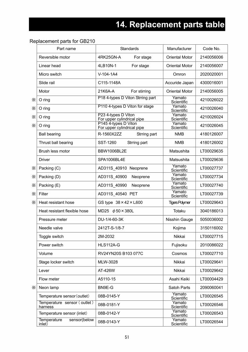
14. Replacement parts table Replacement parts for GB210
Part name Standards Manufacturer Code No.
Reversible motor 4RK25GN-A For stage Oriental Motor 2140056006
Linear head 4LB10N-1 For stage Oriental Motor 2140056007
Micro switch V-104-1A4 Omron 2020020001
Slide rail C115-1148A Accuride Japan 4300016001
Motor 21K6A-A For stirring Oriental Motor 2140056005
※ O ring P18 4-types D Viton Strring part Yamato Scientific 4210026022
※ O ring P110 4-types D Viton for stage Yamato Scientific 4210026040
※ O ring P23 4-types D Viton For upper cylindrical pipe
Yamato Scientific 4210026024
※ O ring P145 4-types D Viton For upper cylindrical pipe
Yamato Scientific 4210026045
Ball bearing R-1560X2ZZ Strring part NMB 4180126007
Thrust ball bearing SST-1260 Strring part NMB 4180126002
Brush less motor BBW1006BL2E Matsushita LT00029635
Driver SPA1006BL4E Matsushita LT00029636
※ Packing (C) AD311S_40910 Neoprene Yamato Scientific LT00027737
※ Packing (D) AD311S_40900 Neoprene Yamato Scientific LT00027734
※ Packing (E) AD311S_40990 Neoprene Yamato Scientific LT00027740
※ Filter AD311S_40540 PET Yamato Scientific LT00027739
※ Heat resistant hose GS type 38×42×L600 Tigers Polymer LT00029643
Heat resistant flexible hose MD25 φ50×380L Totaku 3040186013
Pressure meter DU-1/4-60-3K Nisshin Gauge 5050036002
Needle valve 2412T-S-1/8-7 Kojima 3150116002
Toggle switch 2M-2032 Nikkai LT00027715
Power switch HLS112A-G Fujisoku 2010086022
Volume RV24YN20S B103 077C Cosmos LT00027710
Stage locker switch MLW-3028 Nikkai LT00029641
Lever AT-426W Nikkai LT00029642
Flow meter A5110-15 Asahi Keiki LT00004429
※ Neon lamp BN9E-G Satoh Parts 2090060041
Temperature sensor(outlet) 08B-0145-Y Yamato Scientific LT00026545
Temperature sensor ( outlet )harness 08B-0181-Y Yamato
Scientific LT00026546
Temperature sensor (inlet) 08B-0142-Y Yamato Scientific LT00026543
Temperature sensor(below inlet) 08B-0143-Y Yamato
Scientific LT00026544

52
14. Replacement parts table
Part name Standards Manufacturer Code No.
Interface cable (with a connector) RNJC-RM-20-12-A-1(CN12) Misumi LT00027660
Interface cable (with a connector) RNJC-RF-20-12-A-1(CN11) Misumi LT00027659
Bellows MFK040-L130 For connecting upper cylindrical pipe Mirapro LT00027775
Clamp MCK-1040 Mirapro P57
※ Center ring MCK-2040 Mirapro LT00027798
Blank flange MCK-4040 Mirapro LT00027775
※ Seize heater AD311S_30020 Yamato Scientific LT00027773
Solenoid valve VX2230K-02-1G1 SMC LT00027695
Solenoid valve VX3334K-02-1GR1-B Three-way valve SMC LT00031493
Motor FY8PF15N-D3 For sending liquid Nihon Servo LT00027675
Driver FYD815SD3 For sending liquid Nihon Servo LT00027693
Gear head 8H30FBN-100 For sending liquid Nihon Servo LT00027684
Bearing SSR-1030ZZ For sending liquid NMB 4180126001
※ Teflon flexible tube φ6.35×φ4.35×200 Yamato Scientific 3040000015
Micro switch SS-01GL2 Nozzle por Omron A0020084
Teflon tube φ8×φ6×L1000 Yamato Scientific 3040146003
PLC connection cable GT10-C10-R4-8P Mitsubishi LT00027716
Touch panel GT1030-HBDW 4.5 inches Mitsubishi LT00035099
PLC IN24/OUT16 FX1N-40MR Mitsubishi LT00028131
Output block FX1N-2EYT-BD Mitsubishi LT00027717
Temperature controller TTM204-Q-PI-RSV Toho Denshi LT00027709
ELB BJS203100S1 Matsushita 2060050011
SSR TRS1225 Toho Denshi LT00029541
Relay LY1N AC100V For heater blower Omron LT00027662
Relay MY4N AC100V Omron 2050130003
Socket PTF08A Omron LT00017832
Socket PYF14A Omron LT00017913
Transformer AD21-500AZ TOYOZUMI W0124
Transformer UD22-02KB2 TOYOZUMI LT00029638
Switching power supply LEA50F-24 COSEL LT00027661
※ Liquid sending tube φ2×4×L1000 Silicon Yamato Scientific LT00027796
※ Liquid sending tube φ2×4×L1000 Tiron Yamato Scientific LT00028790
Note: Parts marked with * are consumable parts.

53
14. Replacement parts table
Replacement parts for CF200 Part name Standards Manufacturer Code No.
Spray nozzle set GF200-30000 Yamato Scientific LT00028787
※ O ring P135 4 types D Viton Yamato Scientific 4210026044
※ O ring P16 4 types D Viton Yamato Scientific 4210026021
※ O ring P30 4 types D Viton Yamato Scientific 4210026026
※ O ring P145 4 types D Viton Yamato Scientific 4210026045
※ Packing C GF200_40310 silicon Yamato Scientific LT00028762
Filter chamber GF200_30120 ultra hard glass Yamato Scientific LT00028126
Thrust ball bearing SST-1260 NMB 4180126002 Packing (A) GF300_40160 Silicon Yamato
Scientific LT00024524
Packing (B) GF300_40150 Silicon Yamato Scientific LT00024523
Micro pore plate GF200_40160 SUS304 Yamato Scientific LT00028128
Cap GF300_40100 Silicon Yamato Scientific LT00027544
Flow layer chamber GF200_30070 Ultra hard glass Yamato Scientific LT00028129
Clean out needle additional machining diagram
GF200-40000 14293-6-1/16-SS Secondary machining SSJ LT00028432
※ Packing CP-4042-2-TEF SSJ 3280016002 ※ Gasket (A) CP104369-TEF SSJ 3280016003 ※ Gasket (B) CP3612-TEF SSJ 3280016006 ※ O ring JASO-1017 Haika 4210076002 Filter GF200-30100 polyester Yamato
Scientific LT00028130
Filter packing GF200_40260 silicon Yamato Scientific LT00028458
Hose SRDH(GS type)L800mm Tigers Polymer 3040080004 Hose clip JCS-Win-2A φ35~50 Okada Sangyo LT00027550
Note: Parts marked with * are consumable parts.
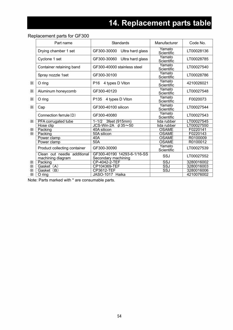
54
14. Replacement parts table
Replacement parts for GF300 Part name Standards Manufacturer Code No.
Drying chamber 1 set GF300-30000 Ultra hard glass Yamato Scientific LT00028136
Cyclone 1 set GF300-30060 Ultra hard glass Yamato Scientific LT00028785
Container retaining band GF300-40000 stainless steel Yamato Scientific LT00027540
Spray nozzle 1set GF300-30100 Yamato Scientific LT00028786
※ O ring P16 4 types D Viton Yamato Scientific 4210026021
※ Aluminum honeycomb GF300-40120 Yamato Scientific LT00027548
※ O ring P135 4 types D Viton Yamato Scientific F0020073
※ Cap GF300-40100 silicon Yamato Scientific LT00027544
Connection ferrule(D) GF300-40080 Yamato Scientific LT00027543
※ PFA corrugated tube 1・1/2 3feet (915mm) Iida rubber LT00027545 Hose clip JCS-Win-2A φ35~50 Iida rubber LT00027550
※ Packing 40A silicon OSAME F0220141 ※ Packing 50A silicon OSAME F0220143 Power clamp 40A OSAME R0100009 Power clamp 50A OSAME R0100012 Product collecting container GF300-30090 Yamato
Scientific LT00027539
Clean out needle additional machining diagram
GF300-40190 14293-6-1/16-SS Secondary machining SSJ LT00027552
※ Packing CP-4042-2-TEF SSJ 3280016002 ※ Gasket (A) CP104369-TEF SSJ 3280016003 ※ Gasket (B) CP3612-TEF SSJ 3280016006 ※ O ring JASO-1017 Haika 4210076002
Note: Parts marked with * are consumable parts.
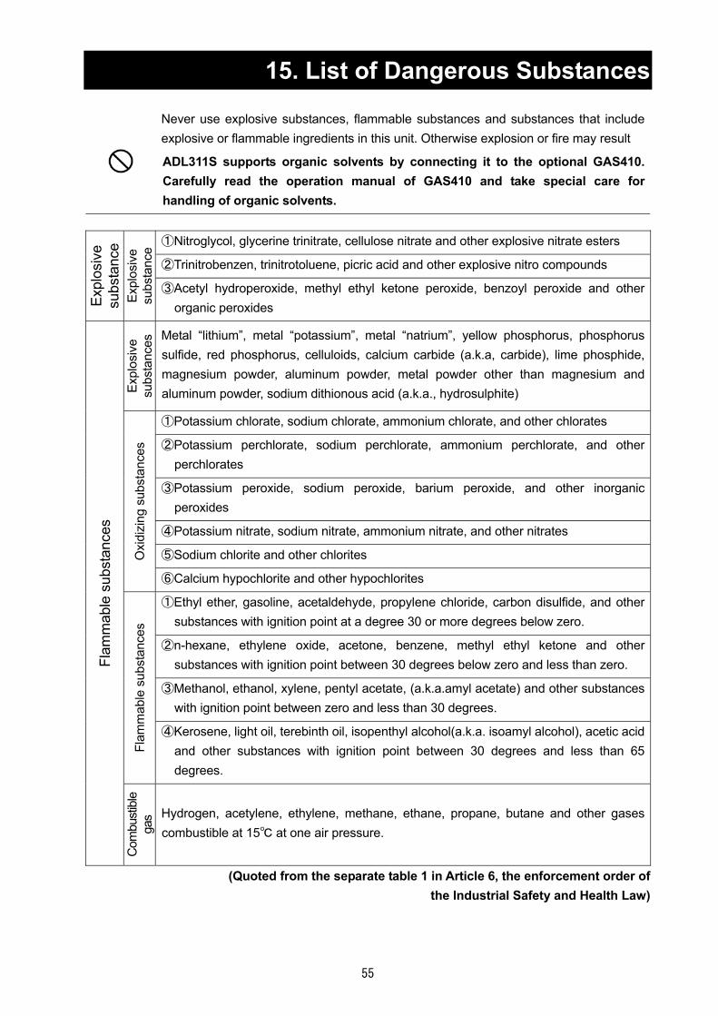
55
15. List of Dangerous Substances
Never use explosive substances, flammable substances and substances that include explosive or flammable ingredients in this unit. Otherwise explosion or fire may result
ADL311S supports organic solvents by connecting it to the optional GAS410. Carefully read the operation manual of GAS410 and take special care for handling of organic solvents.
①Nitroglycol, glycerine trinitrate, cellulose nitrate and other explosive nitrate esters
②Trinitrobenzen, trinitrotoluene, picric acid and other explosive nitro compounds
Expl
osiv
e su
bsta
nce
Expl
osiv
e su
bsta
nce
③Acetyl hydroperoxide, methyl ethyl ketone peroxide, benzoyl peroxide and other organic peroxides
Expl
osiv
e su
bsta
nces
Metal “lithium”, metal “potassium”, metal “natrium”, yellow phosphorus, phosphorus sulfide, red phosphorus, celluloids, calcium carbide (a.k.a, carbide), lime phosphide, magnesium powder, aluminum powder, metal powder other than magnesium and aluminum powder, sodium dithionous acid (a.k.a., hydrosulphite)
①Potassium chlorate, sodium chlorate, ammonium chlorate, and other chlorates
②Potassium perchlorate, sodium perchlorate, ammonium perchlorate, and other perchlorates
③Potassium peroxide, sodium peroxide, barium peroxide, and other inorganic peroxides
④Potassium nitrate, sodium nitrate, ammonium nitrate, and other nitrates
⑤Sodium chlorite and other chlorites Oxi
dizi
ng s
ubst
ance
s
⑥Calcium hypochlorite and other hypochlorites
①Ethyl ether, gasoline, acetaldehyde, propylene chloride, carbon disulfide, and other substances with ignition point at a degree 30 or more degrees below zero.
②n-hexane, ethylene oxide, acetone, benzene, methyl ethyl ketone and other substances with ignition point between 30 degrees below zero and less than zero.
③Methanol, ethanol, xylene, pentyl acetate, (a.k.a.amyl acetate) and other substances with ignition point between zero and less than 30 degrees.
Flam
mab
le s
ubst
ance
s
④Kerosene, light oil, terebinth oil, isopenthyl alcohol(a.k.a. isoamyl alcohol), acetic acid and other substances with ignition point between 30 degrees and less than 65 degrees.
Flam
mab
le s
ubst
ance
s
Com
bust
ible
ga
s Hydrogen, acetylene, ethylene, methane, ethane, propane, butane and other gases combustible at 15 at one air pressure.
(Quoted from the separate table 1 in Article 6, the enforcement order of the Industrial Safety and Health Law)

56
Limited liability
Be sure to use the unit strictly following the handling and operating instructions in this operating instruction. Yamato Scientific Co., Ltd. assumes no responsibility for an accident or a malfunction caused by use of this product in any way not specified in this operating instruction. Never attempt to perform matters prohibited in this operation instruction. Otherwise, an unexpected accident may result.
Notice
Descriptions in this operating instruction are subject to change without notice. We will replace a manual with a missing page or paging disorder.
Instruction Manual PULVIS MINI SPRAY /PULVIS MINI BED GB210A/GB210B Revised Feb. 27, 2012
Yamato Scientific Co., Ltd. 103-8432 2-1-6, Nihonbashi, Honcho, Chuo-ku, Tokyo Customer support center
Tool free: 0120-405525 http://www.yamato-net.co.jp
Top Related