


Languages
Pages
Legal


Fuel Cell Technology
Proton Exchange Membrane Fuel Cells (PEMFCs)
Docent
Jinliang YuanNovember, 2008
Department of Energy Sciences Lund Institute of Technology (LTH), Sweden

Fuel Cell Technology
Four PEMFC stacks illustrating developments through the 1990s. The 1989model on the left has a power density of 0.1kWL−1. The 1996 model on the
right has a power density of 1.1kWL−1.

Fuel Cell Technology
•The PEMFC developments have reached the current densities up to around1Acm−2
or more,
•While at the same time reducing the use of platinum by a factor of over 100 (from 28
mg/cm2
to 0.2
mg/cm2
or less).
•These improvements have led to huge reduction in cost per kilowatt of power, and much improved power density (0.1
to
over 1 kW/L).
•For various applications, two aspects are very similar: the electrolyte used, and the electrode structure and catalyst (both not discussed extensively during the lecturing sessions)
Current Statues
Fuel Cell Technology
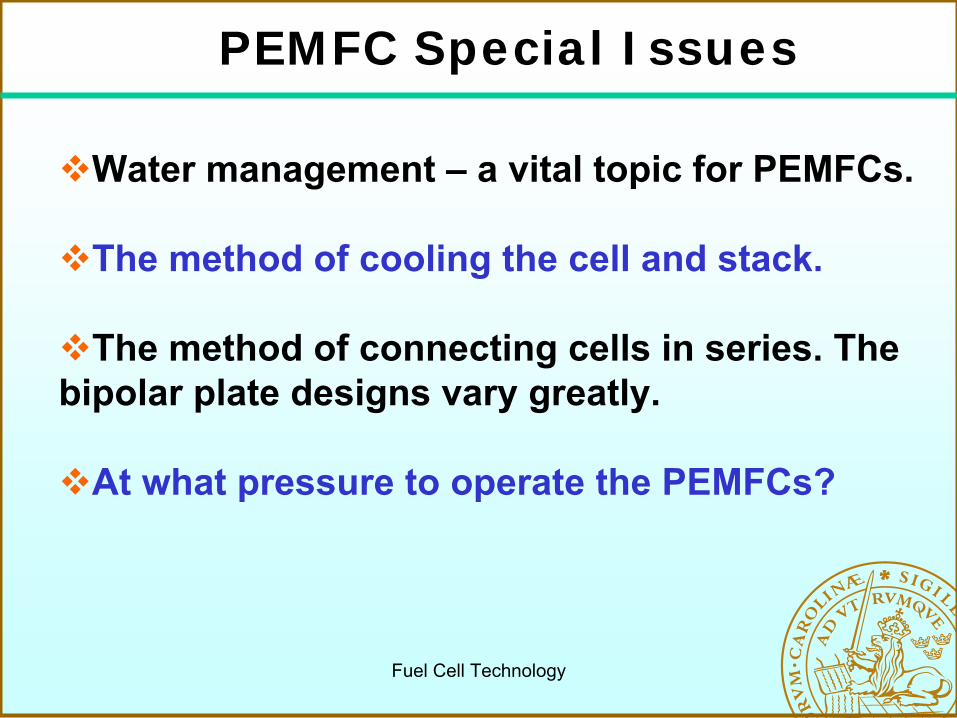
Water management – a vital topic for PEMFCs.
The method of cooling the cell and stack.
The method of connecting cells in series. The bipolar plate designs vary greatly.
At what pressure to operate the PEMFCs?
PEMFC Special Issues

Fuel Cell Technology
• they are chemically resistant,
•
they are strong (mechanically), and so can be made into very thin films, down to 50μm,
•
they are acidic, they can absorb large quantities of water,
•
if they are well hydrated, the H+
ions can move quite freely within the material –
they are good proton conductors, 0.1
Scm−1, but the water content falls, the conductivity falls in a more or less linear fashion.
Main features of Nafion and other fluorosulphonate
ionomers
The structure of Nafion-type membrane materials.

Fuel Cell TechnologyThe structure of carbon-
supported catalyst
Electrodes
Catalyst layer
Diffusion layer (not a good name)
•gas diffusion (transport?),
•current
collecting,
•water removing,
•physical
support.
The structure of a PEMFC electrode (Carbon paper or carbon cloth material)
Fuel Cell Technology
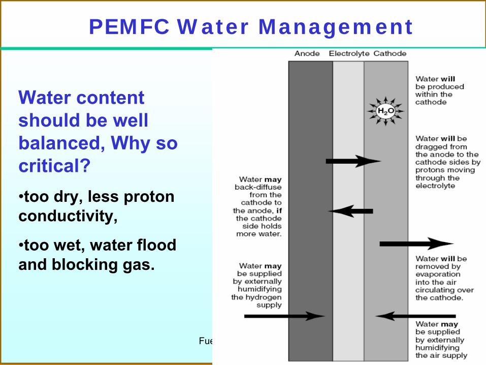
PEMFC Water Management
Water content should
be well
balanced, Why
so critical?•too
dry, less proton
conductivity,
•too
wet, water flood and blocking
gas.

Fuel Cell Technology
Several Complications
•Electro-osmotic drag
-the H+
ions moving from the anode to the cathode pull water molecules with them. Typically between one and five
water molecules are
dragged fro each proton. It becomes more critical at high current densities…
•Another major problem is the drying effect of air at high temperatures.
Solution
to solve these problems is to humidify the air, the hydrogen, or both, before they enter the fuel cell, i.e., add a by-product to the inputs…

Fuel Cell Technology
Air Flows
•Air flows
supplied
at a rate
faster than
that needed and removes
the generated
water in the cathods.
•Air flows
supplied
at a rate
faster than
that needed (stoichiometric
rate) and removes
the generated
water in the cathods.
•Non-linear
relationship
between
the dry
effect
of air and temperature,which
is based
on the relative
humidity, water content
and saturated
vapour pressure, etc.

Fuel Cell Technology
Important Variables
•Humidity ratio
between mw
the mass of water present in the mixture and ma
the mass of dry air. The total mass of the air is mw
+ ma
.
•Relative humidity between Pw
the partial pressure of the water and Psat
the saturated vapour
pressure of the water. It gives a correct feeling of drying effect
or not, e.g., fully
humidified air means that air is unable to hold any more water…
Fuel Cell Technology
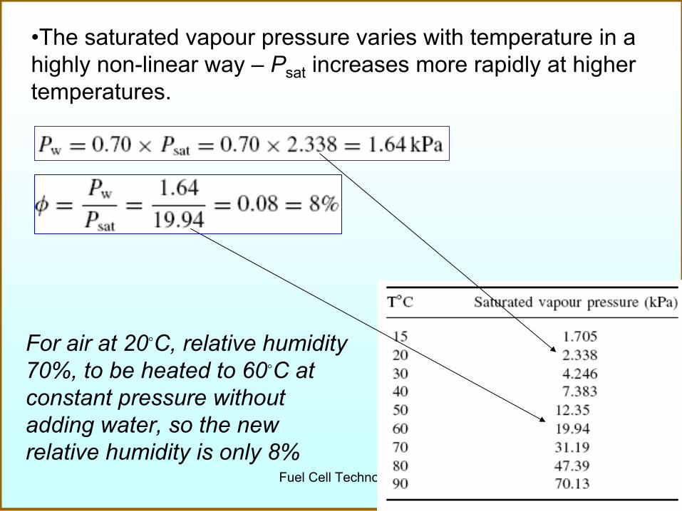
•The saturated vapour
pressure varies with temperature in a highly non-linear way –
Psat
increases more rapidly at higher temperatures.
For air at 20◦C, relative humidity 70%, to be heated to 60◦C at constant pressure without adding water, so the new relative humidity is only 8%

Fuel Cell Technology
Humidity of PEMFC Air
The humidity of the exit air of a fuel cell
Pressure ratio or molar fraction based on the number of moles of species leaving the cell per second
λ, the air stoichiometry, is 2 when T=70oC. E.g., 67% is too dry..
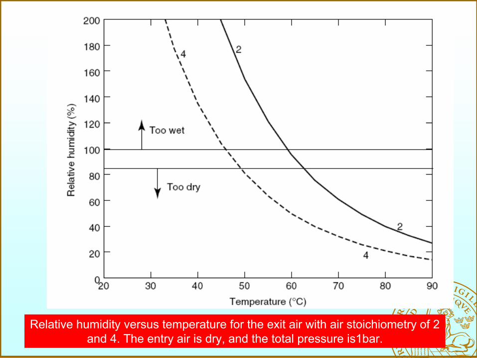
Fuel Cell TechnologyRelative humidity versus temperature for the exit air with air stoichiometry
of 2 and 4. The entry air is dry, and the total pressure is1bar.

Fuel Cell Technology
•At temperatures above about 60◦C, the relative humidity of the exit air is below or well below 100% at all reasonable values of stoichiometry
•Extra humidification of the reactant gases is essential in PEM fuel cells operating at above about 60◦C
Very critical to optimize operating temperatures, i.e., a higher temperature gives a better performance, mainly because the cathode overvoltage reduces. However, once over 60◦C the humidification problems increase, and the extra weight and cost of the humidification equipment can exceed thesavings coming from a smaller and lighter fuel cell.

Fuel Cell Technology
Contra flow of reactant gases to spread
humidification.
•Running PEMFCs
without
external humidification is to set the air stoichiometry
so that the relative humidity of the exit air is
about 100% and to ensure that the cell design enables water balanced within the cell.
•Air and hydrogen flow in opposite directions across the MEA.•The water flow from anode to cathode is the same in all parts, (electro-osmotic drag). •The back diffusion from cathode to anode varies, but is compensated for by the gas circulation.

Fuel Cell Technology
External HumidificationExample: PEMFC operating at 90◦C, inlet pressure of 220 kPa
and exit pressure of 200 kPa, typical air stoichiometry
is 2.
Case 1. inlet ‘normal air’
at 20◦C and 70% relative humidity.
Case 2. inlet air at 80◦C and 90% relative humidity.

Fuel Cell Technology
Fuel Cell Thermal Management
• The electrochemical reactions are exothermic, i.e., the heat is generated together with the contribution of the ohmic resistance;
• For instance, excessive heat generation may result in dehydration of membrane, and in such case, decreased conductivities and thermal stresses are expected, even mechanical failure of fuel cell components.
• Heat removal and proper thermal management are critical design and operating issues in fuel cells;
• Local temperature distribution has significant effects on the PEMFC saturation pressure/phase change.
Fuel Cell Technology
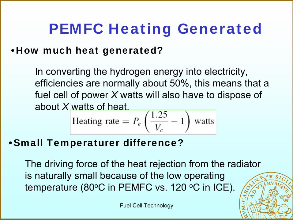
PEMFC Heating Generated•How much heat generated?
In converting the hydrogen energy into electricity, efficiencies are normally about 50%, this means that a fuel cell of power X watts will also have to dispose of about X watts of heat.
•Small Temperaturer difference?
The driving
force
of the heat rejection
from the radiator is naturally
small because
of the low
operating
temperature
(80oC in PEMFC vs. 120 oC in ICE).

Fuel Cell Technology
PEMFC Cooling-Overall
Power Range
Cooling Method
Remarks
Below 100W
Combined reactant
and
cooling
gas
No extra component, too
dry
if
λ
is too
big.100W-1kW Extra
channelsSeperate
reactant
and cooling
airAbove
1kW Extra
channelsWater cooling

Fuel Cell Technology
Best Case: assume power Pe
Watts, operating at 50◦C, 40% of the heat removed by air, specific heat capacity cp
flowing at a rate of m
kg/s, and subject to a temperature change (50-20)oC.

Fuel Cell Technology
Three cells stack, with the bipolar
plate modified for air cooling
using separate
reactant and cooling air.

Fuel Cell Technology
•Air cooling is simpler, but it becomes harder to cool it to a similar temperature, as it gets larger.
•The air channels make the fuel cell stack larger than it needs to be
•The need of PEMFC water cool is greater than with a petrol engine, as the fuel cell performance is more affected by variation in temperature.
Why/When Water Cooling Needed?
PEMFC stack with several
kWe
needs
water cooling…
Top Related