


Languages
Pages
Legal


Scholars' Mine Scholars' Mine
Masters Theses Student Theses and Dissertations
Fall 2016
Protection of a 138/34.5 kv transformer using SEL 387-6 relay Protection of a 138/34.5 kv transformer using SEL 387-6 relay
Aamani Lakkaraju
Follow this and additional works at: https://scholarsmine.mst.edu/masters_theses
Part of the Electrical and Computer Engineering Commons
Department: Department:
Recommended Citation Recommended Citation Lakkaraju, Aamani, "Protection of a 138/34.5 kv transformer using SEL 387-6 relay" (2016). Masters Theses. 7606. https://scholarsmine.mst.edu/masters_theses/7606
This thesis is brought to you by Scholars' Mine, a service of the Missouri S&T Library and Learning Resources. This work is protected by U. S. Copyright Law. Unauthorized use including reproduction for redistribution requires the permission of the copyright holder. For more information, please contact [email protected].

PROTECTION OF A 138/34.5 KV TRANSFORMER USING SEL 387-6 RELAY
by
AAMANI LAKKARAJU
A THESIS
Presented to the Faculty of the Graduate School of the
MISSOURI UNIVERSITY OF SCIENCE AND TECHNOLOGY
In Partial Fulfillment of the Requirements for the Degree
MASTER OF SCIENCE IN ELECTRICAL ENGINEERING
2016
Approved by
Dr. Mariesa L. Crow, Advisor
Dr. Pourya Shamsi
Dr. Jhee Young Joo

2016
Aamani Lakkaraju
All Rights Reserved

iii
ABSTRACT
Schweitzer Engineering laboratories (SEL) donated the SEL 387, SEL 311L, and
SEL 351S relays and the SEL AMS to Missouri University of Science and Technology.
This thesis documents the demonstration approach to set the SEL 387 relay to protect a
grounded wye-grounded wye transformer and then test these settings by injecting fault
currents into the relay using the SEL AMS. This thesis explains the approach to set the
differential element of the SEL 387 relay to protect a transformer against internal faults
and the overcurrent element of the SEL 387 relay to protect transformer against external
faults. A radial power system model is assumed and modeled using ASPEN Oneliner and
Power Flow software. Fault currents obtained from ASPEN model are injected to the
relay using the SEL AMS. Separate tests are performed for the differential element and
the overcurrent element. The objective of testing the differential element is to show that it
is tripping for internal faults and restraining for external faults. The approach used by the
SEL 387 differential relay to make trip decisions is theoretically calculated. These
theoretical results are verified with results obtained from the relay fault event reports. The
instantaneous and time overcurrent elements are tested by running various types of faults
at four different locations. The objective of testing the overcurrent elements is to show
that the instantaneous overcurrent elements are tripping only for transformer primary side
faults and to show that primary side time overcurrent element is coordinating with the
secondary side time overcurrent element.

iv
ACKNOWLEDGEMENTS
I would first like to express my sincere gratitude to my advisor, Dr. Mariesa L.
Crow for her immense support and encouragement without which I would not have
completed my thesis. I would like to thank my committee members Dr. Pourya Shamsi
and Dr. Jhi-Young Joo for serving as members of my committee. My sincere thanks to
Professor Paul J Nauert for answering my doubts and giving valuable suggestions on my
thesis. His courses helped me learn the important concepts of Protective Relaying which
are the building blocks of my thesis work. I would like to sincerely thank Andrew Burich,
Protection Engineer at SEL for answering all the questions related to thesis. I would also
like to thank all the engineers of SEL who helped to get my doubts related to SEL relays
clarified. I would like to thank my parents and brother for supporting and motivating me
during the difficult times. Finally, I would like to thanks my friends for their support.
v
TABLE OF CONTENTS
Page
ABSTRACT…………………………………………………………………………….. iii
ACKNOWLEDGEMENTS……………………………………………………………... iv
LIST OF FIGURES……………………………………………………………………. ix
LIST OF TABLES………………………………………………………………………xiv
SECTION
1. INTRODUCTION .............................................................................................. 1
2. BACKGROUND ................................................................................................ 3
2.1. TRANSFORMER BASICS ....................................................................... 3
2.2. TRANSFORMER PROTECTION ............................................................ 4
Internal Faults ................................................................................... 6
External Faults. ................................................................................. 6
Overexcitation. .................................................................................. 6
Overload Faults. ................................................................................ 7
2.3. TRANSFORMER PROTECTION FOR INTERNAL FAULTS USING
DIFFERENTIAL RELAY ......................................................................... 8
Percentage Restraint Differential Relay Scheme ............................ 10
Factors To Be Considered While Setting A Differential Relay ...... 11
2.3.2.1. Power transformer phase shift………………………...…..11
2.3.2.2. Tap compensation mismatch…………………………...…12
2.3.2.3. Load/No load tap changer……………………………...…13
2.3.2.4. Inrush current……………...………………………...……13

vi
2.3.2.5. Overexcitation…………….……………………...……….16
2.4. TRANSFORMER THROUGH FAULT PROTECTION USING
OVERCURRENT RELAYS ................................................................... 17
Description Of Overcurrent Relays. ............................................... 18
Overcurrent Relay Coordination ..................................................... 19
Setting An Overcurrent Relay ......................................................... 22
2.4.3.1. Phase time overcurrent (51P)…………...………………...22
2.4.3.2. Ground time overcurrent (51N)…………………………...23
2.4.3.3. Phase/ground instantaneous elements (50P/50N)...………23
Transformer Through-Fault Withstand Capability Curve .............. 23
Transformer Through-Fault Withstand Capability Curve Shift ...... 26
2.5. GROUND FAULT PROTECTION OF TRANSFORMER .................... 29
3. SEL 387-6 RELAY SITING – THEORETICAL DESCRIPTION .................. 33
3.1. CT RATIO (CTR) .................................................................................... 33
CT Accuracy Class [1][10] ............................................................. 34
CT Saturation Considerations For Setting Protective Relays ......... 36
CT Ratio Calculation For 138/34.5 kV Transformer………….. ... 37
3.1.3.1. Checking the 500:5 CT on the 138kV winding for
saturation…...……………………………………………..38
3.1.3.2. Checking the 1500:5 CT on the 34.5kV winding for
saturation…………………...………………………...…...39
3.2. CONNECTION COMPENSATION (WnCTC) ...................................... 40
Procedure To Select Values For WnCTC [5] ................................. 42
Winding Compensation For 138/34.5 kV Transformer … ............. 44
3.3. PERCENTAGE DIFFERENTIAL RELAY SETTINGS ........................ 45

vii
Restrained Element Operating Current Pickup (087P) [5] ............. 45
Restrained Element Slope 1 Settings (SLP1) [3] ............................ 45
Restrained Current Slope 1 Limit (IRS1) [5] .................................. 45
Restrained Element Slope 2 Settings (SLP2).................................. 46
Unrestrained Element Pickup (87U) [5] ......................................... 46
3.4. SEL 387-6 RELAY DIFFERENTIAL ELEMENT TRIP LOGIC [5] .... 47
3.5. OVERCURRENT ELEMENT SETTINGS ............................................ 51
Power System Model-Using ASPEN.............................................. 51
Setting Of Overcurrent Relays ........................................................ 51
Time Current Curves (TCC) ........................................................... 52
3.5.3.1. Curves for phase overcurrent relays………...…………….53
3.5.3.2. Curves for ground overcurrent relays...………............…...53
3.5.3.3. Transformer damage curve...……………………………...53
4. SETTING RELAY USING SEL 5030 SOFTWARE ....................................... 61
4.1. CONFIGURATION SETTINGS ............................................................. 61
4.2. GENERAL DATA ................................................................................... 62
4.3. DIFFERENTIAL ELEMENT SETTINGS .............................................. 63
4.4. OVERCURRENT ELEMENT SETTINGS ............................................ 63
4.5. TRIP EQUATIONS ................................................................................. 66
4.6. UNLATCH TRIP EQUATIONS ............................................................. 66
4.7. EVENT REPORT .................................................................................... 66
4.8. OUTPUT EQUATIONS .......................................................................... 67
4.9. SEL 387 RELAY SETTINGS- SCREEN SHOTS .................................. 67

viii
5. EXPERIMENTS ............................................................................................... 70
5.1. TEST FOR DIFFERENTIAL ELEMENT .............................................. 70
Three Phase Fault At Location 1 .................................................... 71
Phase To Phase Fault At Location 2 ............................................... 73
Three Phase Fault At Location 3 .................................................... 75
Phase To Phase Fault At Location 4 ............................................... 77
5.2. TEST FOR OVERCURRENT ELEMENTS ........................................... 79
Three Phase Fault At Location 1 .................................................... 80
Phase To Phase Fault At Location 1 ............................................... 80
Three Phase Fault At Location 2 .................................................... 81
Three Phase Fault At Location 3 .................................................... 81
Three Phase Fault At Location 4 .................................................... 82
Single Line To Ground Fault At Location 1 ................................... 83
Single Line To Ground Fault At Location 2 ................................... 83
Single Line To Ground Fault At Location 3 ................................... 83
Single Line To Ground Fault At Location 4 ................................... 84
APPENDICES
A. GETTING STARTED WITH ACSELERATOR QUICKSET……………..117
B. SEL AMS SETUP…………………………………………….…………..... 122
C. PROCEDURE TO RETRIEVE EVENT REPORTS FROM RELAY……...131
REFERENCES………………………………………………………………................140
VITA…………………………………………………………………………................142

ix
LIST OF FIGURES
Figure Page
2.1. Basic structure of a transformer under no load ........................................................... 4
2.2. Winding configurations of transformers ...................................................................... 5
2.3. One line diagram for the protection of a 138/34.5 kV
transformer using the SEL 387 relay .......................................................................... 8
2.4. Normal operating conditions, op e eI I I .................................................................. 9
2.5. Internal fault condition 1 2OP F F e eI I I I I .......................................................... 10
2.6. Percentage differential relay slope characteristics ..................................................... 14
2.7. Slope change when the harmonic restraint setting is enabled .................................... 20
2.8. Relay typical TCC curves in a radial system ............................................................. 22
2.9. US Extremely inverse curve U4 ................................................................................ 24
2.10. Through-fault withstand capability curve for frequent
and infrequent faults of Category I transformer and for
infrequent faults of Category II and III transformers ............................................... 28
2.11. Through-fault withstand capability curves for
frequent faults of Category II transformer ............................................................... 29
2.12. Through-fault withstand capability curve for frequent
faults of Category III transformer and for infrequent or
frequent faults of Category IV transformers ........................................................... 30
2.13. Current distribution in a delta-wye transformer for
transformer secondary side faults ........................................................................... 32
3.1. Equivalent circuit diagram of current transformer ..................................................... 33
3.2. Typical excitation curves for a multi ratio C class transformers ............................... 35
3.3. Decrease in secondary current than the expected primary
current divided by turns ratio value due to CT saturation ........................................ 37

x
3.4. Screen shot of TTY window in ASPEN showing the
X/R ratio for a high side close-in three phase fault .................................................. 38
3.5. 600:5 multiratio CT curve .......................................................................................... 40
3.6. Specifications of the SEL 387-6 relay ....................................................................... 41
3.7. Screen shot of TTY window in ASPEN showing X/R ratio
for low side three phase fault .................................................................................... 42
3.8. 2000:5 multiratio CT curve ........................................................................................ 44
3.9. Currents going into the primary side and out on the secondary side ......................... 44
3.10. Winding connections, phase shifts and compensation direction ............................. 46
3.11. 138/34.5 kV wye-wye transformer under consideration .......................................... 47
3.12. SEL 387-6 relay differential element settings ......................................................... 47
3.13. Winding n currents used to calculate IOP and IRT ................................................. 49
3.14. Differential element 87-1 quantities ........................................................................ 50
3.15. Differential element 87-1 quantities ........................................................................ 52
3.16. One line diagram for model under consideration .................................................... 53
3.17. TCC curves for phase overcurrent relays................................................................. 55
3.18. TCC curves for ground overcurrent relay ................................................................ 58
3.19. TCC curves on the low side of the transformer coordinating
with the transformer damage curve drawn with respect to
the low side 34.5 kV voltage................................................................................... 59
3.20. The TCC curve on the high side of the transformer coordinating
with the transformer damage curve drawn with respect to the
high side 138 kV voltage ........................................................................................ 60
4.1. Screen shot of SEL 387 relay settings ....................................................................... 68
4.2. Screen shot of SEL 387 relay settings ....................................................................... 69
5.1. Four fault scenarios considered for experiment ......................................................... 71

xi
5.2. Approximate location of operating points for the considered faults.......................... 79
5.3. Fault currents obtained from ASPEN for three phase fault at location 1 .................. 85
5.4. SEL AMS setting for three phase fault at location 1 ................................................. 85
5.5. Event report for three phase fault at location 1 .......................................................... 86
5.6. Differential event report for three phase fault at location 1 ....................................... 86
5.7. Fault currents obtained from ASPEN for phase to phase at location 2 ..................... 87
5.8. SEL AMS setting for phase to phase fault at location 2 ............................................ 87
5.9. Event report for phase to phase fault at location 2 ..................................................... 88
5.10. Differential event report for phase to phase fault at location 2 ................................ 88
5.11. Fault currents obtained from ASPEN for a three phase fault at location 3 .............. 89
5.12. SEL AMS setting for three phase fault at location 3 ............................................... 89
5.13. Event report showing pickup of relay bits for a
three phase fault at location 3 .................................................................................. 90
5.14. Event report showing tripping of overcurrent element
for three phase fault at location 3 ............................................................................. 91
5.15. Differential event report for three phase fault at location 3 .................................... 91
5.16. Fault currents obtained from ASPEN for phase to
phase fault at location 4 .......................................................................................... 92
5.17. SEL AMS setting for phase to phase fault at location 4 .......................................... 92
5.18. Event report showing pickup of overcurrent element
for phase to phase fault at location 4 ....................................................................... 93
5.19. Event report showing tripping of overcurrent element
for phase to phase fault at location 4 ....................................................................... 94
5.20. Differential event report for phase to phase fault at location 4 ................................ 94
5.21. Event report showing tripping of overcurrent
element for three phase fault at location 1 ............................................................... 95

xii
5.22. Fault currents obtained from ASPEN for phase
to phase fault at location 1 ...................................................................................... 96
5.23. SEL AMS setting for phase to phase fault at location 1 .......................................... 96
5.24. Event report showing tripping of overcurrent
element for phase to phase fault at location 1 .......................................................... 97
5.25. Fault currents obtained from ASPEN for three phase fault at location 2 ................ 98
5.26. SEL AMS setting for three phase fault at location 2 ............................................... 98
5.27. Event report showing pickup of overcurrent
element for three phase fault at location 2 ............................................................... 99
5.28. Event report showing tripping of overcurrent
element for three phase fault at location 2 ............................................................ 100
5.29. Event report showing pickup of overcurrent
element for three phase fault at location 3 ........................................................... 101
5.30. Event report showing tripping of overcurrent
element for three phase fault at location 3 ............................................................ 102
5.31. Fault currents obtained from ASPEN for three phase fault at location 4 .............. 103
5.32. SEL AMS setting for three phase fault at location 4 ............................................. 103
5.33. Event report showing pickup of overcurrent element
for three phase fault at location 4 ........................................................................... 104
5.34. Event report showing tripping of overcurrent element
for three phase fault at location 4 .......................................................................... 105
5.35. Fault currents obtained from ASPEN for single
line to ground fault at location 1 ............................................................................ 106
5.36. SEL AMS setting for single line to ground fault at location 1 .............................. 106
5.37. Event report showing tripping of ground overcurrent
element for single line to ground fault at location 1 .............................................. 107
5.38. Fault currents obtained from ASPEN for
single line to ground fault at location 2 ................................................................ 108
5.39. SEL AMS setting for single line to ground fault at location 2 .............................. 108

xiii
5.40. Event report showing pickup of ground overcurrent
element for single line to ground fault at location 2 .............................................. 109
5.41. Event report showing tripping of ground overcurrent
element for single line to ground fault at location 2 .............................................. 110
5.42. Fault currents obtained from ASPEN for
single line to ground fault at location 3 ................................................................. 111
5.43. SEL AMS setting for single line to ground fault at location 3 .............................. 111
5.44. Event report showing pickup of ground overcurrent
element for single line to ground fault at location 3 .............................................. 112
5.45. Event report showing tripping of ground overcurrent
element for single line to ground fault at location 3 .............................................. 113
5.46. Fault currents obtained from ASPEN for
single line to ground fault at location 4 ................................................................. 114
5.47. SEL AMS setting for single line to ground fault at location 4 .............................. 114
5.48. Event report showing pickup of ground overcurrent
element for single line to ground fault at location 4 .............................................. 115
5.49. Event report showing tripping of ground overcurrent
element for single line to ground fault at location 4 .............................................. 116

xiv
LIST OF TABLES
Table Page
2.1. Transformer categories ............................................................................................. 27
3.1. Parameters of the power system model .................................................................... 54
3.2. Overcurrent relay settings in ASPEN ....................................................................... 56

1. INTRODUCTION
Schweitzer Engineering laboratories (SEL) donated the SEL 387, SEL 311L, and
SEL 351S relays and the SEL AMS to Missouri University of Science and Technology.
This thesis documents the demonstration approach to set the SEL 387 relay to protect the
transformer and then test these settings by injecting fault currents into the relay using the
SEL AMS. This is intended to provide additional documentation to better use the relays
for a hands on experience on setting relays in a classroom setting.
The basic components of power systems are generators, transformers, high
voltage transmission lines, and distribution lines. The damage to any of these equipment
components may result in a system outage. The main cause of damage in power system is
a short circuit or fault. A fault is caused due to conditions such as lightening, earthquakes,
wind, contact of animals with equipment etc. [1]. During a fault condition, abnormal
conditions such as high currents, over voltages, low voltages, and over/under frequency
may exist in the system. These abnormal conditions often exceed the rating of the
equipment and lead to equipment damage.
A fault may be a single phase to ground, a double phase to ground, phase to phase
or a three phase fault. A single phase to ground fault occurs the most frequently of all
faults. The desirable response to a single phase to ground fault is to disconnect the
faulted part momentarily until the fault clears to prevent cascading. This disconnection is
accomplished by means of a circuit breaker controlled by the protective relays.
A protective relay or relay is defined by IEEE Standard C37.90 as ‘‘an electric
device that is designed to respond to input conditions in a prescribed manner and, after
specified conditions are met, to cause contact operation or similar abrupt change in

2
associated electric control circuits.” The electronic device refers to the relay that opens
the contacts of the circuit breaker (known as tripping) when there exists an abnormal
condition such as high currents, over voltages, or low voltages. In the same manner, it is
should not respond to normal operating conditions or load conditions. The relays are
usually given inputs from current transformers (CT), voltage transformers (VT), or both.
These CTs and VTs are known as instrument transformers. These instrument
transformers usually step down the currents and voltages of the primary or main circuit to
lower values that can be safely applied to the relays.
The relay may be either electromechanical or a digital. Electromechanical relays
use the electromagnetic principle which converts electrical quantities such as current and
voltage to mechanical quantities such as torque. The digital relays are built with
microprocessors, digital signal processors, and A/D converters to convert electrical
quantities to digital signals. Reliability, speed, low burden, multifunctional capability
features available in digital relays have made them more dependable than
electromechanical relays. Digital usage over the past two to three decades has increased
and many industries are replacing their electromechanical relays with digital relays.
Based on the logic of protection, relays can be classified as overcurrent relays,
differential relays, distance relays, or directional relays. For example, an overcurrent
relay operates if the current through the relay exceeds the pickup value. A distance relay
operates if the ratio of voltage to current is below a preset value. The relay under
consideration, SEL 387, is a multifunctional digital relay which includes differential
protection, overcurrent protection, restricted earth fault protection, and transformer
thermal protection as functionalities.

3
2. BACKGROUND
2.1. TRANSFORMER BASICS
According to ANSI C57.12.80, a transformer is defined as “a static electric device
consisting of a winding, or two or more coupled windings, with or without a magnetic
core, for introducing mutual coupling between electric circuits. Transformers are
extensively used in electric power systems to transfer power by electromagnetic
induction between circuits at the same frequency, usually with changed values of voltage
and current.” A simple single phase transformer consists of two coils, known as the
primary and secondary windings, wound on an iron core separated electrically but linked
magnetically. When an ac voltage V1 is supplied to primary winding, a small current,
known as the exciting current, is produced in this primary winding and an alternating flux
is produced in the iron core. This flux is transferred to the secondary coil through the
iron core which in turn induces voltage V2 in the secondary, as shown in Figure 2.1.
The voltage is stepped up or down based on the number of primary and secondary
winding turns. The voltage is proportional to number of turns. If number of primary turns
is greater than secondary turns, the voltage is stepped down. If the number of primary
turns is less than secondary turns, the voltage is stepped up.
In power systems, the transformer is the most important component used to step
up or down different voltage levels. According to ANSI C57.12, transformers with a high
side voltage or low side voltage ratings greater than 69kV are used at transmission levels.
Small transformers with a high side voltage rating less than 69kV are classified as
distribution transformers and are used at distribution levels. The transformers used in

4
power systems may be of two windings or three windings. The transformer windings are
usually connected in delta or wye connection. Different combinations of two winding
transformer connections are shown in Figure 2.2. Auto transformers are also a common
connection type in power systems.
2.2. TRANSFORMER PROTECTION
The main objective of transformer protection is to detect transformer internal
faults with high sensitivity and restrain for the faults on the system for which tripping of
the transformer is not required [1]. The transformers have to be protected for internal
faults, external faults, overexcitation, and overload conditions. Overexcitation protection
is provided mostly for generator step up unit (GSU) transformers as these transformers
are operated under the control of automatic voltage regulator of generator during start up
or shut down [9]. Transformers at distribution levels are protected against internal and
Figure 2.1. Basic structure of a transformer under no load [12]

5
external faults. Overload protection may also be included for these transformers. In
general, transformers with ratings greater than 10MVA are protected using a differential
relay [1]. Transformers rated less than 10MVA, which are mainly distribution
transformers, are protected using fuses on their high side. Transformers with low ratings
are relatively inexpensive and therefore differential protection, which is expensive, is not
feasible. Fuses are less expensive as they do not make use of a circuit breaker. Therefore
the protection of small transformers with fuses is more economically feasible. The
conditions for which transformers have to be protected are discussed under sections 2.2.1.
to 2.2.4.
Figure 2.2. Winding configurations of transformers

6
Internal Faults. Faults in the transformer zone are internal faults. Internal
faults are due to transformer insulation breakdown. Insulation breakdown occurs due to
following factors:
• ageing of insulation due to overtemperature
• contaminated oil
• partial discharges in the insulation
• transient overvoltages
Breakdown of insulation leads to severe earth faults, short circuit faults, turn to
turn faults, core faults, and tank faults. The occurrence of any of these faults results in
severe damage to transformer. Differential protection is commonly used to protect the
transformer from internal faults.
External Faults. Faults external to the transformer zone are external or
through faults. External faults impose severe stress on transformers if these faults are not
cleared by their corresponding primary protection devices. Stress on transformer causes
transformer overheating and damage. External fault protection is provided by
overcurrent relays or fuses. These protection devices serve as backup to downstream
devices.
Overexcitation. An overexcitation fault is caused by an increase in voltage
or decrease in frequency. As per IEEE C37.91 “Overexcitation of a transformer can occur
whenever the ratio of the per unit voltage to per unit frequency (V/Hz) at the secondary
terminals of a transformer exceeds its rating of 1.05 per unit (PU) on the transformer base
at full load, 0.8 power factor, or 1.1 PU at no load” [9]. The transformer core saturates
and increases the iron loss during overexcitation. The volts per hertz (V/hz) protection is

7
provided to protect against overexcitation. This protection is usually provided for
generator and GSU transformer together based on the combined generator and
transformer overexcitation capability.
Overload Faults. An overload increases copper losses and causes
temperature rise. Thermal protection is usually provided to transformer to protect against
this condition. Generally an alarm is used for protection instead of tripping.
The transformer under consideration in this demonstration is a 138/34.5 kV,
80MVA grounded wye-grounded wye power transformer. The SEL 387 relay is used to
protect this transformer. The differential element of this relay is used to provide
protection for internal faults. To provide protection for external faults, the overcurrent
element is used.
Figure 2.3 shows the one line diagram of the transformer protection scheme using
the SEL 387 relay. ANSI device number 87 represents the differential relay. CT1 and
CT2A are the CTs located on the high side and low side, respectively, and are used for
differential protection. ANSI device numbers 51P and 51G represent the phase and
ground overcurrent relays respectively. ANSI device numbers 50P and 50G represents
the phase and ground instantaneous overcurrent relays respectively. ANSI device number
52 represents a circuit breaker. Circuit breaker 52-1 is on the high side of the transformer.
Circuit breaker 52-2 is on the low side of the transformer. For testing purpose, differential
element and time overcurrent elements have been used.

8
2.3. TRANSFORMER PROTECTION FOR INTERNAL FAULTS USING
DIFFERENTIAL RELAY
Differential protection is the best protection technique due to selectivity [1].
Selectivity is the ability of the relay to trip for internal faults and restrain for external
faults. The differential relay is used to provide instantaneous protection to a specific
component such as a generator, transformer, line, or bus without the need for
coordination with the relays protecting other equipment outside the zone of equipment
under consideration. Other commonly used protection relays, such as distance relays or
overcurrent relays that extend their protection to adjacent zones, need to be coordinated
with the devices protecting the zone adjacent to transformer zone. The transformers with
ratings greater than 10 MVA are protected by differential relays. For transformers with
Figure 2.3. One line diagram for the protection of a 138/34.5 kV transformer using the
SEL 387 relay

9
higher ratings, differential relays are used because they provide instantaneous protection
to internal faults.
The working principle of a differential relay is based on Kirchhoff’s current law
according to which current flowing into a node is equal to current flowing out of a node.
The net current entering the protection zone through the CTs secondary is calculated by
the relay. Under ideal non fault or external fault conditions, the net current in the
protection zone is zero. Under non-ideal conditions, current flows through the protection
zone even under normal conditions due to transformer excitation currents, CT error, and
relay error [1]. This condition is shown in Figure 2.4.
When there is an internal fault, the fault currents from both the windings will be
flowing into the protection zone in opposing directions as shown in Figure 2.5. The relay
trips if currents flowing in the protection zone exceed the pickup value. The pickup of a
Figure 2.4. Normal operating conditions, op e eI I I [1]

10
differential relay is set based on the transformer inrush current, CT errors, relay errors,
and other factors.
Percentage Restraint Differential Relay Scheme. The SEL 387 relay uses
a percentage restraint differential relay scheme. This scheme operates on the ratio of the
magnitudes of pick up to restraint currents or the value of slope of the curve as shown in
Figure 2.6. The operating current is defined as the phasor sum of all currents flowing into
the protection zone. The restraint current has many definitions. It can be defined as
follows
RST W1 W2 W3
RST W1 W2 W3
I K I I I .. or (2.1)
I Max I , I , I .. (2.2)
where IW1, IW2, IW3, … are the secondary currents flowing in winding 1, winding 2, and
winding 3, etc., and K is a constant defined by the relay manufacturers. For the SEL 387
Figure 2.5. Internal fault condition 1 2OP F F e eI I I I I [1]
11
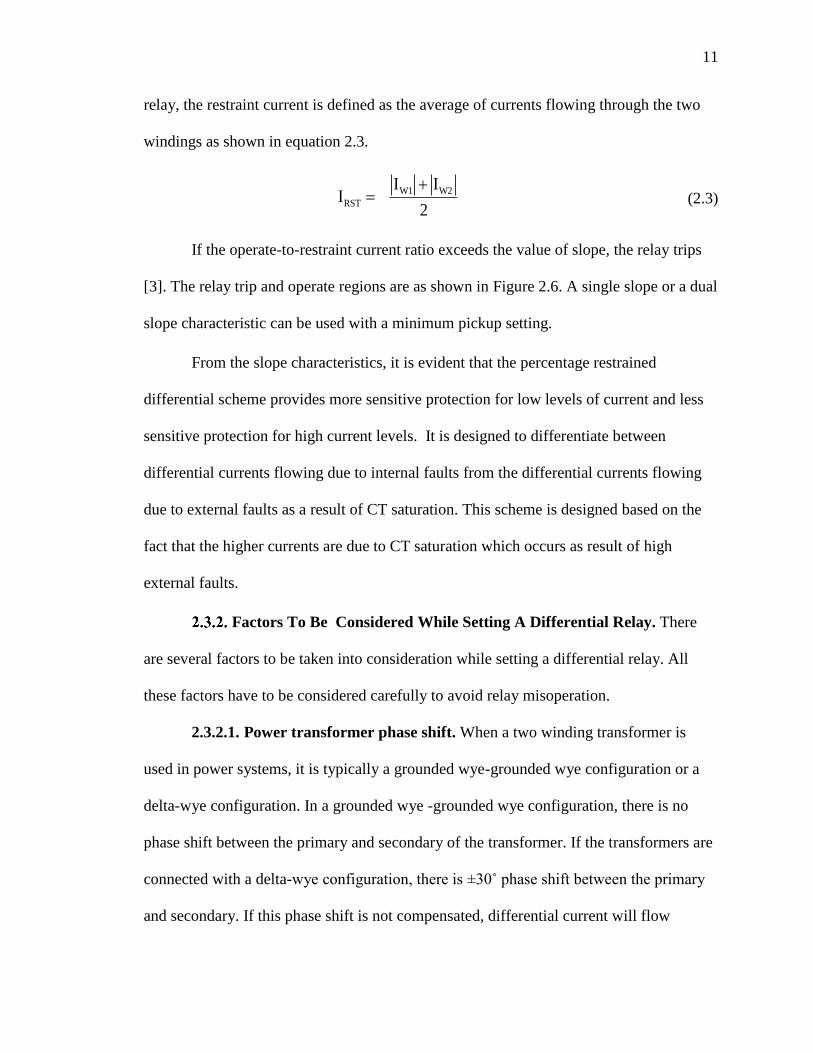
relay, the restraint current is defined as the average of currents flowing through the two
windings as shown in equation 2.3.
W1 W2
RST
I II
2
(2.3)
If the operate-to-restraint current ratio exceeds the value of slope, the relay trips
[3]. The relay trip and operate regions are as shown in Figure 2.6. A single slope or a dual
slope characteristic can be used with a minimum pickup setting.
From the slope characteristics, it is evident that the percentage restrained
differential scheme provides more sensitive protection for low levels of current and less
sensitive protection for high current levels. It is designed to differentiate between
differential currents flowing due to internal faults from the differential currents flowing
due to external faults as a result of CT saturation. This scheme is designed based on the
fact that the higher currents are due to CT saturation which occurs as result of high
external faults.
Factors To Be Considered While Setting A Differential Relay. There
are several factors to be taken into consideration while setting a differential relay. All
these factors have to be considered carefully to avoid relay misoperation.
2.3.2.1. Power transformer phase shift. When a two winding transformer is
used in power systems, it is typically a grounded wye-grounded wye configuration or a
delta-wye configuration. In a grounded wye -grounded wye configuration, there is no
phase shift between the primary and secondary of the transformer. If the transformers are
connected with a delta-wye configuration, there is ±30˚ phase shift between the primary
and secondary. If this phase shift is not compensated, differential current will flow
12
through the protection zone. The phase shift between the primary and secondary of the
power transformer can be compensated by using proper CT connections. The traditional
way to provide compensation is to connect a wye CT for a delta winding and a delta CT
for a wye winding. This connection compensates for the delta-wye phase shift of the
power transformer. For a wye connected winding, a delta connected CT is used to remove
zero sequence currents. Zero sequence current has to be eliminated to avoid misoperation
of the differential relay due to line to ground faults on the wye side of a delta-wye
connected transformer. In digital relays, delta-wye phase shift compensation and zero
sequence current elimination can be attained by providing appropriate settings to the
relay. With the availability of this feature, any configuration can be chosen for the CTs.
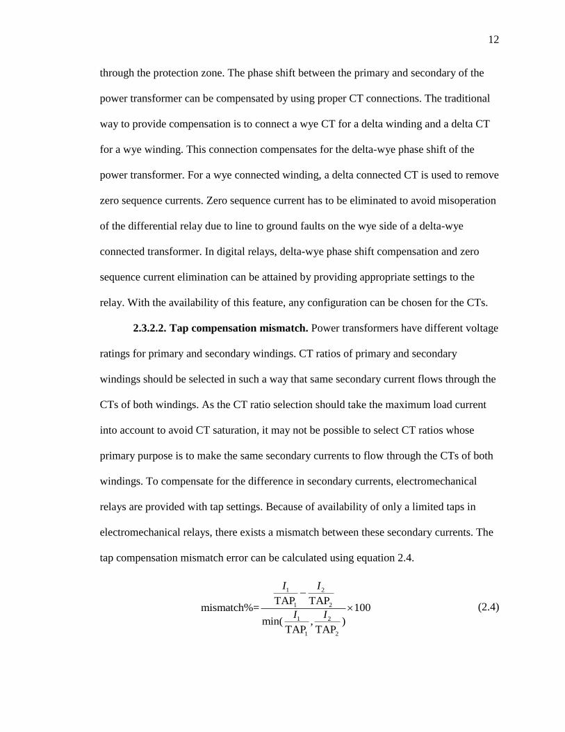
2.3.2.2. Tap compensation mismatch. Power transformers have different voltage
ratings for primary and secondary windings. CT ratios of primary and secondary
windings should be selected in such a way that same secondary current flows through the
CTs of both windings. As the CT ratio selection should take the maximum load current
into account to avoid CT saturation, it may not be possible to select CT ratios whose
primary purpose is to make the same secondary currents to flow through the CTs of both
windings. To compensate for the difference in secondary currents, electromechanical
relays are provided with tap settings. Because of availability of only a limited taps in
electromechanical relays, there exists a mismatch between these secondary currents. The
tap compensation mismatch error can be calculated using equation 2.4.
1 2
1 2
1 2
1 2
TAP TAPmismatch%= 100
min( , )TAP TAP
I I
I I
(2.4)

13
where I1 and I2 are transformer full load secondary currents in winding 1 and winding 2
CTs respectively. TAP1 and TAP2 are the taps selected from the available taps to
minimize the mismatch error.
However in digital relays, there is no tap compensation mismatch error and thus
this error can be assumed to be zero. The relay tries to automatically adjust the tap to
make mismatch error zero.
2.3.2.3. Load/No load tap changer. Transformers are usually provided with on
load/no load tap changers to regulate the voltage based on system load conditions. The
tap changer changes the transformer turns ratio, and thus the voltage of the primary or
secondary winding. The transformer’s on load tap changers are used when voltage
regulation can be performed on load without interruption to power. On the other hand, no
load tap changers are used when voltage regulation has to be done while the transformer
is on no load. The relays settings are usually made considering the transformer primary
and secondary fixed rated voltages. But these voltages vary in accordance with load
conditions. An error of ±5% for a no load tap changer and an error of ±10% for a load tap
changer can be considered in differential relay settings to account for transformer tap
changes due to load conditions [3].
2.3.2.4. Inrush current. The transformer inrush current is the high magnitude
current flowing through the transformer at three instances: during energization of the
transformer, during the transformer voltage recovery after an external fault is cleared, and
during parallel operation of two or more transformers [4]. Any condition that causes
instantaneous change of the transformer flux linkages can cause large inrush currents to
flow. As the duration of flow of these currents is very short, they do not cause any fault.

14
But these currents may cause the differential relay to operate. The relationship between
the flux produced in the core of the transformer and the applied voltage in general is
given by equations 2.5 and 2.6.
( )( )
d tV t
dt
(2.5)
( ) ( )t v t K (2.6)
If V(t)= Vmsin(ωt), then Φ(t) will be a cosine function. From equations (2.5)-(2.6),
it is evident that the applied voltage and core flux are in quadrature with each other.
However, if the transformer is energized at the instant the voltage is zero, the core flux at
Figure 2.6. Percentage differential relay slope characteristics [3]

15
this particular instant is also zero. The value of flux obtained after the first half cycle of
voltage, when the flux and voltage together start from zero can be calculated as follows,
( ) sin( )
0
sin( )
0
sin( ) ( ) 2
0
m
m
m m
V t dt
Vt dt
t d t
(2.7)
where mm
V
is the maximum value of flux. The flux at the end of first half cycle of
voltage becomes as high as twice the maximum value of flux, 2Φm. The core begins to
saturate when the value of flux reaches its maximum value Φm. A large amount of current
is drawn from the system to produce the remaining flux after the core saturates. This is
the magnetizing inrush current and is as high as ten times the current rating of the
transformer. These large currents are responsible for tripping differential relays.
Inrush currents are characterized with even harmonic content at large levels. This
fact can be used to distinguish an inrush current from a fault current. The SEL 387 relay
is equipped with harmonic blocking and harmonic restraint feature to provide security to
relays against high inrush currents which are rich in 2nd and 4th harmonic content [4]. If
the harmonic blocking setting is enabled, the differential relay is blocked when the ratio
of second or forth harmonic operating current and fundamental frequency operating
current exceeds a preset second or forth harmonic threshold. Enabling the harmonic
restraint setting in relay increases the slope of the relay. As shown in Figure 2.7, the slope
is increased by adding a harmonic restraint constant C. This can be mathematically
represented as follows:

16
IOP = SLP1*IRT+C (2.8)
100 100
2 42 4
n nC IW C IW CPCT PCT
(2.9)
where
IOP: operating current
IRT: restraint current
SLP1: value of slope without harmonic restraint
PCT2: 2nd harmonic threshold
PCT4: 4th harmonic threshold
ƩIWnC2: sum of 2nd harmonic currents through all the windings
ƩIWnC4: sum of 4th harmonic currents through all the windings [5].
2.3.2.5. Overexcitation. Transformer overexcitation is caused due to increase in
voltage or decrease in frequency as the magnetic flux inside the transformer is directly
proportional to the applied voltage and inversely proportional to frequency [5]. Due to
overstressing the transformer with high flux, overexcitation results in core saturation that
causes a higher magnitude current to flow into transformer primary winding than out of
transformer secondary winding. The differential relay might interpret this incorrectly as a
fault current and trip. Large overexcitation currents might be undesirable as they cause
transformer heating and ultimately damage the transformer. But differential protection
cannot reliably detect overexcitation currents as the relay characteristics do not match
with the transformer overexcitation capability limit [1]. Instead, a separate protection
17
scheme such as Volts/hertz must be used to protect transformer from high overexcitation
currents.
The overexcitation currents are abundant in odd harmonic content, mostly third or
fifth, whereas in fault currents, the content of these harmonics is comparatively low. This
fact can be used to differentiate an overexcitation current from the fault current and
prevent the operation of differential relay for overexcitation currents [4]. Third harmonic
content cannot be used to detect overexcitation condition as it is eliminated with a delta
winding similar to how a zero sequence current is eliminated using delta winding. Using
a mechanism to eliminate fifth harmonic content can prevent differential relay from
tripping for overexcitation conditions. The SEL 387 relay has ‘harmonic blocking’
feature that blocks the relay if the fifth harmonic content exceeds a specified limit. When
the ratio of fifth harmonic operating current and fundamental frequency operating current
exceeds a preset fifth harmonic threshold, the differential relay is blocked.
2.4. TRANSFORMER THROUGH FAULT PROTECTION USING
OVERCURRENT RELAYS
The differential relay can provide instantaneous protection to internal faults. To
protect a transformer against external faults, an overcurrent relay can be used. For
transformers rated less than 10MVA, where differential protection is not used, a fuse on
the high side of transformer can provide external fault protection [1]. When a differential
protection is used, overcurrent elements are generally used as local backup to the
differential relay and at the same time provide protection for transformer external faults.
An instantaneous overcurrent element is used as a backup for a differential relay. Time
overcurrent elements are used exclusively to provide protection for external faults in case
18
downstream relays fail to operate. The objectives of using a time overcurrent relay on
primary and secondary of transformer can be summarized as follows:
The primary function of the overcurrent relay on the primary side is to provide
primary backup protection for the secondary side relays and thereby protect the
transformer against external faults. The relay settings should be selected to coordinate
with the transformer damage curve while coordinating with its upstream and downstream
devices. The relay curve should lie to the left of the transformer damage curve for all
faults.
The primary function of the overcurrent relay on the secondary side of the
transformer is to provide backup protection for downstream relays and protect
transformer from external faults. This can be achieved by coordinating the secondary side
relay with the transformer damage curve. This relay has to coordinate with primary side
relay as well as downstream relays.
Description Of Overcurrent Relays. Overcurrent relays respond to faults
by tripping if the magnitude of the current sensed by the relay exceeds the pickup setting.
The pickup setting of the relay is the minimum current at which relay starts to operate.
Non-directional overcurrent relays are often used for protecting radial systems. In a radial
power system, the flow of power is only in one direction from the substation to the loads.
In the absence of distributed generation, there will be no fault current contribution from
the downstream system in such a system. It is important to use directional overcurrent
relays if the system is of the network or ring type where flow of power may be from

19
multiple directions. The choice of directional relays for such systems enables good
selective operation for faults.
The overcurrent relays are classified based on the trip duration as either
instantaneous overcurrent relays or time overcurrent relays. Instantaneous overcurrent
relays trip for faults without any time delay. They are usually set to act instantaneously
for the faults in the zone they are primarily protecting without overreaching. Time
overcurrent relays are often used to trip with time delay to provide primary protection for
the faults in the zone they are protecting and backup protection for faults in the adjacent
zones. This time delay is provided to coordinate with upstream and downstream relays
and thereby avoid misoperation. The operation time of time overcurrent relays decreases
as the magnitude of the current increases. A separate protection is provided for phase
faults and ground faults. Ground fault currents are usually small in magnitude compared
to phase fault currents. So separate ground fault relays are needed which are set more
sensitively for ground fault protection.
Overcurrent Relay Coordination. A fault needs to be cleared quickly
before the equipment it is protecting is damaged. At the same time, the faulted area has to
be isolated with as much little load outage as possible. For a particular fault, the device
near the fault must operate first to isolate as many loads as possible from outage. This is
the main idea behind coordinating relays. For every relay in power systems, there is
usually a backup relay to operate if the primary relay fails to operate for a fault in its
zone. Coordination has to be attained with this backup relay to interrupt power to few
loads as possible in the process of clearing a fault. In a radial system, such as the system

20
under consideration, a minimum coordinating time interval of 0.3 seconds has to be
maintained to avoid misoperation. This 0.3 seconds time interval includes
Relay operating time - 1 cycle
Lockout relay operating time - 1 cycle
Breaker operating time - 3 cycles
Breaker failure time - 10 cycles if a breaker failure scheme exists, otherwise is
zero
Margin - 10 cycles margin is typical
All these factors sum to 24 cycles. To be more conservative, a coordinating time interval
of 18 cycles or 0.3 seconds is considered in a radial system.
Figure 2.7. Slope change when the harmonic restraint setting is enabled

21
The overcurrent relay pickup setting is selected based on load conditions, load
imbalances, and fault conditions. Setting the time overcurrent phase and ground relay
requires selection of the time dial and curve. The parameters relay curve and time dial are
selected in such a way that 0.3 seconds coordinating time interval is maintained between
a primary relay and its next upstream or downstream relay. Time current curves (TCC)
are usually provided by the relay manufacturers. There are 4 different types of curves for
any relay: extremely inverse, very inverse, inverse, and moderately inverse curves. To
attain good coordination, relays in the downstream are usually assigned curves that are
more inverse than curves assigned to upstream relays in a typical radial system as the one
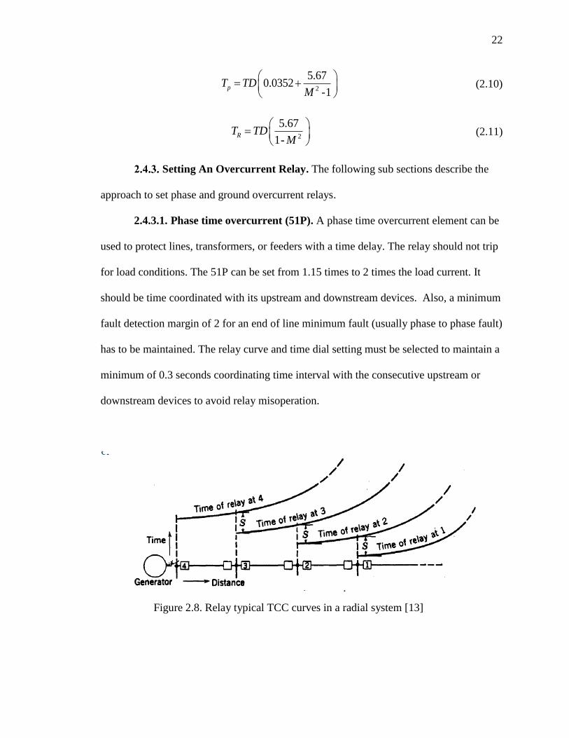
shown in Figure 2.8.
The SEL 387 relay has two types of curves: the US standard curves (U1, U2, U3,
U4) and the IEC curves (C1, C2, C3, C4). Curves U1, U2, U3, and U4 respectively are
US moderately inverse, inverse, very inverse, and extremely inverse curves whereas C1,
C2, C3, and C4 respectively are the IEC class A or moderately inverse, IEC class B or
inverse, IEC class C or very inverse, and IEC class D or extremely inverse curves. Any
curve that attains good coordination with upstream and downstream devices can be
chosen. US curves coordinate well with ABB and GE’s electromechanical relays. IEC
curves coordinate well with European relays or relays of many other countries.
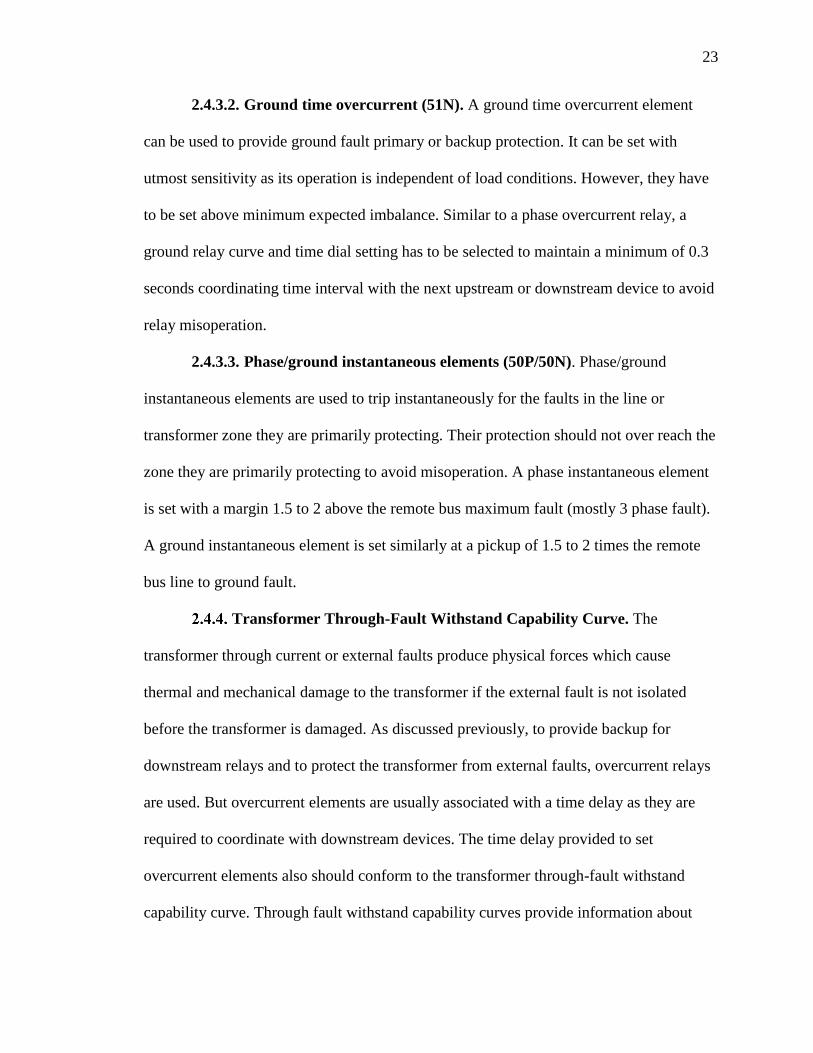
A sample family of US extremely inverse curves is shown in Figure 2.9. The curves are
governed by the equations 2.10 and 2.11, where TP is the operating time, TR is the reset
time, TD is the time dial setting, and M is the multiple of pickup current.
22
2
5.670.0352
-1pT TD
M
(2.10)
2
5.67
1-RT TD
M
(2.11)
Setting An Overcurrent Relay. The following sub sections describe the
approach to set phase and ground overcurrent relays.
2.4.3.1. Phase time overcurrent (51P). A phase time overcurrent element can be
used to protect lines, transformers, or feeders with a time delay. The relay should not trip
for load conditions. The 51P can be set from 1.15 times to 2 times the load current. It
should be time coordinated with its upstream and downstream devices. Also, a minimum
fault detection margin of 2 for an end of line minimum fault (usually phase to phase fault)
has to be maintained. The relay curve and time dial setting must be selected to maintain a
minimum of 0.3 seconds coordinating time interval with the consecutive upstream or
downstream devices to avoid relay misoperation.
Figure 2.8. Relay typical TCC curves in a radial system [13]
23
2.4.3.2. Ground time overcurrent (51N). A ground time overcurrent element
can be used to provide ground fault primary or backup protection. It can be set with
utmost sensitivity as its operation is independent of load conditions. However, they have
to be set above minimum expected imbalance. Similar to a phase overcurrent relay, a
ground relay curve and time dial setting has to be selected to maintain a minimum of 0.3
seconds coordinating time interval with the next upstream or downstream device to avoid
relay misoperation.
2.4.3.3. Phase/ground instantaneous elements (50P/50N). Phase/ground
instantaneous elements are used to trip instantaneously for the faults in the line or
transformer zone they are primarily protecting. Their protection should not over reach the
zone they are primarily protecting to avoid misoperation. A phase instantaneous element
is set with a margin 1.5 to 2 above the remote bus maximum fault (mostly 3 phase fault).
A ground instantaneous element is set similarly at a pickup of 1.5 to 2 times the remote
bus line to ground fault.
Transformer Through-Fault Withstand Capability Curve. The
transformer through current or external faults produce physical forces which cause
thermal and mechanical damage to the transformer if the external fault is not isolated
before the transformer is damaged. As discussed previously, to provide backup for
downstream relays and to protect the transformer from external faults, overcurrent relays
are used. But overcurrent elements are usually associated with a time delay as they are
required to coordinate with downstream devices. The time delay provided to set
overcurrent elements also should conform to the transformer through-fault withstand
capability curve. Through fault withstand capability curves provide information about
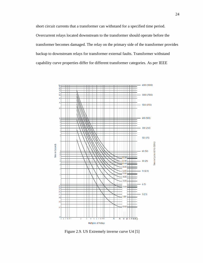
24
short circuit currents that a transformer can withstand for a specified time period.
Overcurrent relays located downstream to the transformer should operate before the
transformer becomes damaged. The relay on the primary side of the transformer provides
backup to downstream relays for transformer external faults. Transformer withstand
capability curve properties differ for different transformer categories. As per IEEE
Figure 2.9. US Extremely inverse curve U4 [5]

25
C57.12.00, transformers are categorized as shown in Table 2.1 according to kVA ratings.
The duration of short circuit of Category I transformers can be determined by the
equation 2.12, where t is duration in seconds and I is the symmetrical short-circuit current
in multiples of normal base current.
2
1250 t
I (2.12)
For Category II, III, and IV transformers, the duration of the short circuit is
limited to 2 seconds. Symmetrical short circuit currents for Category I and II transformers
are calculated based on transformer impedance. The symmetrical short circuit current for
Category III and IV transformers is calculated based on transformer impedance [9].
A different through-fault protection curve is applied for different transformer
applications i.e., there is separate through-fault withstand capability curve for
transformers subjected to infrequent faults and transformers subjected to frequent faults.
For example, transformers typically found in industrial, commercial and institutional
power systems with secondary side conductors enclosed in conduit or isolated are
subjected to faults less frequently. On the other hand, transformers found in utility
distribution substations with overhead lines connected to secondary windings are subject
to frequent faults. If a transformer is subjected to faults infrequently, the transformer is
typically protected only against thermal damage. A transformer subjected to faults
frequently has to be protected against both thermal and mechanical damage. The through-
fault withstand capability curve selected should reflect both possibility of thermal
damage and mechanical damage. The TCC relay curves on the primary and secondary of
the transformer along with downstream relays for which transformer relays are providing
backup should lie to the left of transformer damage curve to properly protect transformer

26
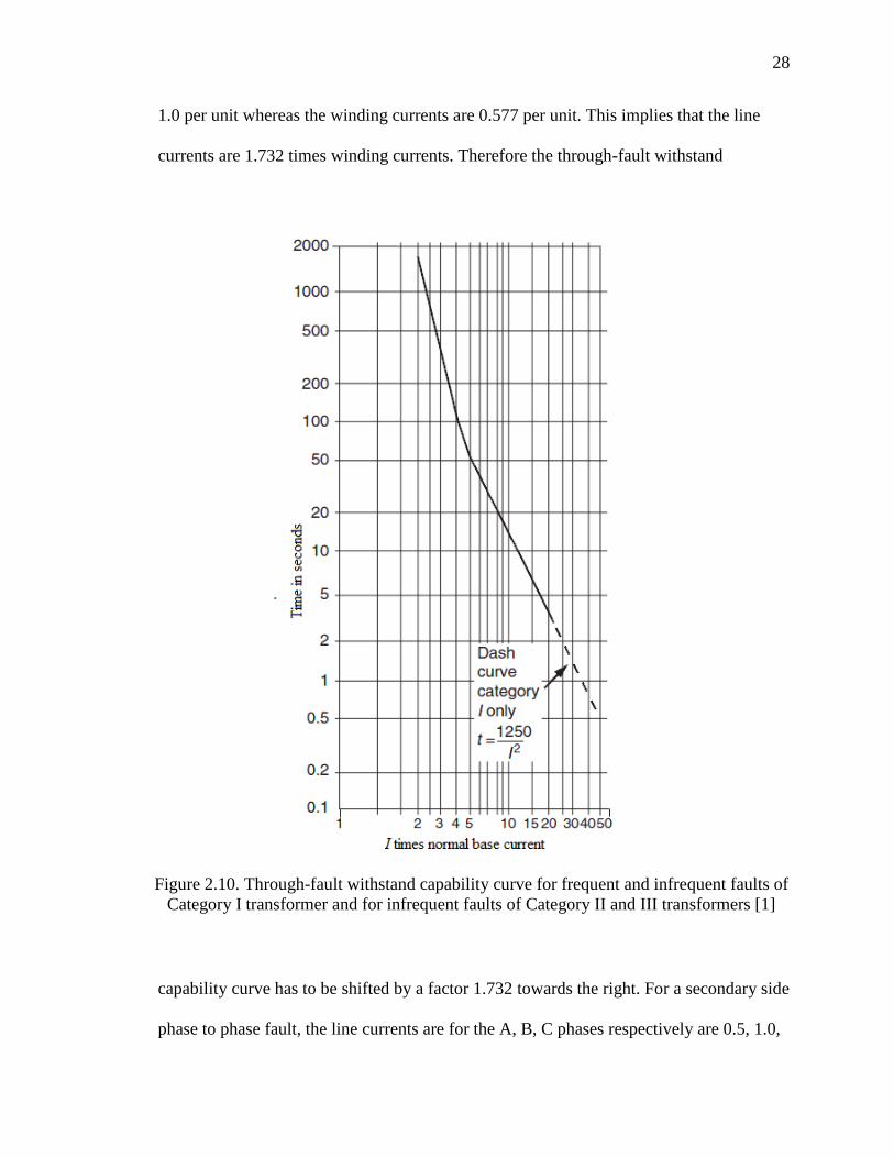
for low side uncleared faults. For Category I transformers, only a thermal protection
curve can be considered as shown in Figure 2.10. This curve can be used for both
frequent and infrequent faults of category I transformers. For category II and III
transformers with infrequent faults, the thermal protection curve as shown in Figure 2.10
is used. For transformers with frequent faults, the mechanical damage curve must be
considered. For a Category II transformer with frequent faults, the curves as shown in
Figure 2.11 with mechanical damage curves represented with dotted line can be
considered. The choice of curve is based on transformer impedance (% Z). For Category
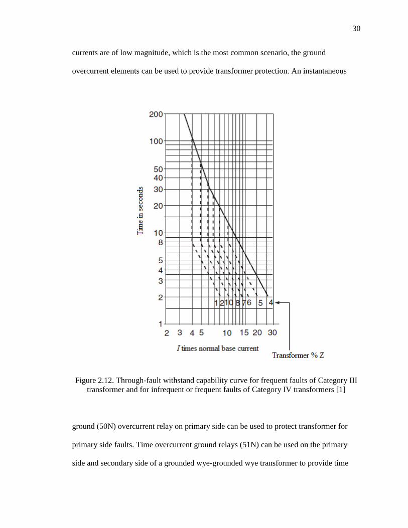
III transformers with frequent faults, the curve as shown in Figure 2.12 is used. This
curve reflects both thermal and mechanical damage. For Category IV transformers, the
same curve as shown in Figure 2.12, which reflects both thermal and mechanical damage,
can be considered for both frequent and infrequent faults [9].
Transformer Through-Fault Withstand Capability Curve Shift. When
there is a delta winding, the line currents are different from the phase currents for
different fault types. This difference must be considered when coordinating relays with
the transformer through-fault withstand capability curve. For example, consider a fault
scenario on the secondary side of a delta-wye two winding step down transformer. In this
transformer configuration, the primary side (delta) leads the secondary side (grounded
wye) by 30˚. Fault currents distribution for secondary side three phase, phase to phase,
and phase to ground faults are shown in Figure 2.13. In these figures, the largest phase
current is designated as 1.0 per unit. Unlike a wye-wye transformer which has
comparable per unit fault currents flowing through both the windings for all types of
faults, a delta-wye transformer has different values of currents flowing through the
27
primary and secondary. For a wye side three phase fault, 1.0 per unit line currents flow
through both primary and secondary windings. While for a wye side phase to phase fault,
the primary side phase A, B, C currents are 0.5 per unit, 1.0 per unit, and 0.5 per unit
respectively, and the secondary side phase A, B, C currents are 0.0, 0.866 per unit and
0.866 per unit, respectively. For a secondary side phase A to ground fault, the line
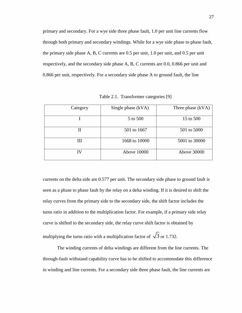
Table 2.1. Transformer categories [9]
Category Single phase (kVA) Three phase (kVA)
I 5 to 500 15 to 500
II 501 to 1667 501 to 5000
III 1668 to 10000 5001 to 30000
IV Above 10000 Above 30000
currents on the delta side are 0.577 per unit. The secondary side phase to ground fault is
seen as a phase to phase fault by the relay on a delta winding. If it is desired to shift the
relay curves from the primary side to the secondary side, the shift factor includes the
turns ratio in addition to the multiplication factor. For example, if a primary side relay
curve is shifted to the secondary side, the relay curve shift factor is obtained by
multiplying the turns ratio with a multiplication factor of 3 or 1.732.
The winding currents of delta windings are different from the line currents. The
through-fault withstand capability curve has to be shifted to accommodate this difference
in winding and line currents. For a secondary side three phase fault, the line currents are
28
1.0 per unit whereas the winding currents are 0.577 per unit. This implies that the line
currents are 1.732 times winding currents. Therefore the through-fault withstand
capability curve has to be shifted by a factor 1.732 towards the right. For a secondary side
phase to phase fault, the line currents are for the A, B, C phases respectively are 0.5, 1.0,
Figure 2.10. Through-fault withstand capability curve for frequent and infrequent faults of
Category I transformer and for infrequent faults of Category II and III transformers [1]

29
and 0.5 per unit respectively. The winding currents are 0.5, 0.5, and 0.0 per unit. The
through-fault withstand capability curve has to be shifted by a factor of 2 towards the
right.
2.5. GROUND FAULT PROTECTION OF TRANSFORMER
For a grounded wye-grounded wye transformer, the differential relay can provide
protection for internal ground faults if their current magnitudes are high. If the ground
Figure 2.11. Through-fault withstand capability curves for frequent faults of Category II
transformer [1]
30
currents are of low magnitude, which is the most common scenario, the ground
overcurrent elements can be used to provide transformer protection. An instantaneous
Figure 2.12. Through-fault withstand capability curve for frequent faults of Category III
transformer and for infrequent or frequent faults of Category IV transformers [1]
ground (50N) overcurrent relay on primary side can be used to protect transformer for
primary side faults. Time overcurrent ground relays (51N) can be used on the primary
side and secondary side of a grounded wye-grounded wye transformer to provide time

31
delayed ground fault protection of the transformer and to provide back up ground fault
protection for downstream relays. A ground differential relay or a restricted earth fault
(REF) element can be used on secondary side to protect wye windings. It detects a fault
only if current flows through the neutral of the grounded wye winding.
For a delta grounded-wye connected transformer, the 51N relay on the primary
side cannot see the faults on the secondary side as the delta winding traps zero sequence
currents. To provide ground fault protection to a delta-grounded wye transformer, the
51N on the delta side should be supplemented with a ground differential protection on the
wye side. The 51N on the primary side can only detect ground faults on the primary side
[9]. Ground differential protection can be replaced with a 51N and/or 50N in the neutral
of the grounded wye transformer. This relay not only provides protection for ground
faults close to the transformer neutral, but also provides back up protection for
downstream ground overcurrent relays [15].

32
Figure 2.13. Current distribution in a delta-wye transformer for secondary side faults [1]

33
3. SEL 387-6 RELAY SITING – THEORETICAL DESCRIPTION
3.1. CT RATIO (CTR)
Current transformers are used to scale down the primary currents to small
magnitudes so that they can be safely applied to protective relays. Figure 3.1 represents
an equivalent circuit of a current transformer. The impedance across the secondary
winding, ZE, has nonlinear characteristics. Its value depends on the excitation voltage Es.
The maximum value of Es that a CT can sustain is given by equation 3.1.
max4.44sV f A N B (3.1)
where f is the system frequency, A is the cross sectional area of the core in square inches,
N is the number of secondary turns, and Bmax is the maximum flux density of the core in
lines per square inch.
In Figure 3.1, Rs represents the secondary winding resistance, XL represents the
leakage reactance, and ZB is the sum of the input impedance of relay and lead resistance.
Figure 3.1. Equivalent circuit diagram of current transformer [16]

34
The curve drawn relating the excitation voltage VS and the excitation current IE is
the CT excitation curve. Figure 3.2 represents the CT excitation curves for a multi-ratio
class C CT. When the voltage developed across the CT burden increases due to an
increase in burden, the primary fault current, the presence of a DC component in the
primary fault current, and the flux in the CT core, will increase. The excitation current IE
increases, consequently the secondary current IS decreases. If the increase in current does
not increase the excitation voltage, this indicates that the CT is saturated. In Figure 3.2,
when the operating point reaches the horizontal line, the CT is said to saturate. When the
CT saturates, the primary current is not reproduced in the secondary. The knee, or
effective point of saturation indicated by point A, is defined as the point at which the
tangent to the excitation curve makes a 45˚ angle with the abscissa for a CT with a non-
gapped core and an angle of 30˚ with the abscissa for a CT with a gapped core.
CT Accuracy Class [1][10]. CTs can be categorized based on levels of
accuracy. CT standard classes are C, T, and K for relaying purposes. Class C designates a
CT that has negligible leakage flux. For C class CTs, the excitation characteristics can be
used to determine the CT performance. A K class CT is similar to a C class CT and has a
knee point voltage of at least 70% of the secondary terminal voltage rating. T class CTs
have significant leakage impedance. Performance is not easily calculated for T class CTs,
therefore manufacturer test curves are used. A CT is designated by its class type followed
by a number which represents the secondary terminal voltage rating. The number
indicates the secondary terminal voltage (VB) that the transformer can deliver to a
standard burden at 20 times the rated secondary current without exceeding the 10% ratio
correction. For relaying, standard voltage burdens are 100, 200, 400, and 800 V with

35
standard burdens designated with B-1, B-2, B-4, and B-8 respectively at 0.5 power factor.
The standard burdens are in ohms () obtained by dividing voltage by 20 times rated
current. The standard rated secondary CT current is 5 amperes in the USA. For a class
C400 CT, the C represents the CT class, and the 400 indicates a VB of 400V. The
standard burden for this CT can be obtained as follows:
secondary terminal voltagestandard burden = (3.2)
20*CTsecondary rated current
400 = 4
20*5
Hence the standard burden for C400 CT is given as B-4.
Figure 3.2. Typical excitation curves for a multi ratio C class transformers [1]

36
CT Saturation Considerations For Setting Protective Relays. During CT
saturation, the secondary current waveform becomes distorted. The secondary current
will have short duration peaks as shown in Figure 3.3. The peak current is less than the
actual primary current divided by the CT ratio value. The secondary RMS current value
is typically 5 to 8% of the primary current divided by the turns ratio value. For example,
a fault current in primary amperes is 10,000 applied to a CT with ratio of 100:5 will yield
a CT secondary current 500 A. But the CT can only tolerate a current up to 20 times the
CT standard secondary rating i.e., 100 amperes. Hence this results in CT saturation. The
CT saturation can cause the secondary current to be as low as 8% of the peak value that is
expected. For the above example, the secondary peak current obtained due to CT
saturation is given by 0.08*500*√2 = 56.6 A. This reduction in current will interfere with
normal relay operation. Because the relay receives a reduced current, the operating time
of the relay is much longer than it would be without any CT saturation. An upstream
relay with a higher CT ratio might trip for such a fault [17]. Instantaneous overcurrent
relays are preferred for correct operation since their tripping time is less than the time
taken by CT to enter into saturation [16]. In case of a differential relay, unequal
saturation of CTs during external faults results in false differential current flowing in the
protection zone. This is handled by percentage differential scheme with variable or dual
slope.
The two main factors to be considered for CT selection are avoiding CT
saturation and ensuring that the sensitivity of the relay is maintained. The CT ratio has to
be carefully selected to avoid CT saturation. Selecting a CT with the primary rated above
the maximum full load primary current is suggested. This selection ensures that nearly 5

37
amperes current flows through the secondary for full load current. If the CTR is set too
high to avoid saturation, then it can have a negative impact on the overall sensitivity of
the relay [19].
If the following inequality holds, then the CT is not in saturation [10]:
20 1 f b
XI Z
R
(3.3)
where If is the maximum fault current in per unit of CT rating, Zb is the CT burden in per
unit of standard burden, and X/R is the X/R ratio of the primary fault circuit.
CT Ratio Calculation For 138/34.5 KV Transformer.
MVA rating of transformer = 80 MVA
Maximum current rating = MVA/√3*kV = 334.7A primary
= 1338.8 A secondary
Figure 3.3. Decreases in secondary current than the expected primary
current divided by turns ratio value due to CT saturation [10]

38
The primary side CT ratio can be selected as 500:5 or 100 and the secondary side CT
ratio as 1500:5 or 300 to avoid saturation.
3.1.3.1. Checking the 500:5 CT on the 138kV winding for saturation.
Step 1: The X/R ratio can be obtained from ASPEN by running a close-in three
phase fault (maximum fault). The result can be viewed on the TTY window as shown in
Figure 3.4. The X/R ratio of 8.54 is indicated.
Step 2: If = maximum fault current as obtained from ASPEN/ CT primary rating
If = 1805/500= 3.61 pu.
Step 3: The available CT is a C200, 600:5 multiratio CT with a 500: 5 tap
selected. Figure 3.5 shows the excitation curve for the 600:5 multiratio CT for which the
following values are used: CT burden = 0.279 Ω, Resistance of leads= 0.252, and relay
resistance = 0.0108 which can be obtained from the manual as shown in Figure 3.6.
Figure 3.4. Screen shot of TTY window in ASPEN showing the X/R ratio for a high side
close-in three phase fault

39
The total burden is the sum of the CT burden, resistance of leads, and relay resistance:
= 0.279+0.252+0.0108 = 0.5418 Ω. The standard burden for the C200 accuracy class CT
is 2Ω, and since we are using 500:5 tap, the standard burden is scaled as 2*(500/600) =
1.67Ω. Therefore, Zb in per unit on standard burden base is 0.5418/1.67 = 0.324.
Step 4: Substituting these values into equation (3.3) yields:
(1+8.54)*3.61*0.324 = 11.16 < 20
Hence, a CT ratio selection of 500:5 will not cause saturation.
3.1.3.2. Checking the 1500:5 CT on the 34.5kV winding for saturation.
Step 1: The X/R ratio can be obtained from ASPEN by running a close-in three
phase fault (maximum fault). The results can be viewed on TTY window as shown in
Figure 3.7 yielding an X/R ratio of 11.01.
Step 2: If = maximum fault current as obtained from ASPEN/ CT primary rating
If= 4472/1500 = 2.98 pu.
Step 3: The available CT is a C400, 2000:5 multiratio CT with a 1500:5 tap
selected. Figure 3.8 gives the excitation cure for a 2000:5 multiratio CT. CT burden =
1.003 Ω, the resistance of leads = 0.252, and the relay resistance = 0.0108. The total
burden is 1.003+0.252+0.0108 = 1.2658 Ω and the standard burden for a C400 accuracy
class CT = 4Ω. Since the CT has a 1500:5 tap, the standard burden is scaled as
4*(1500/2000) = 3Ω, and Zb in per unit on standard burden base = 1.2658/3 = 0.4219.
Step 4: Substituting into equation (3.3) yields
(1+11.0143)*2.98*0.4219 = 15.1 < 20
Hence, the CT ratio selection of 1500:5 will not cause saturation.

40
3.2. CONNECTION COMPENSATION (WnCTC)
As discussed in Section 2.3.2.1, the phase shift between the primary and
secondary windings of the transformer must be considered while setting a differential
relay. If this phase shift is not compensated, a false differential current flows through the
protection zone, which may cause the relay to misoperate. In the SEL 387 relay, proper
selection of values for WnCTC (n is 1 for winding 1, 2 for winding 2, so on) provides
compensation for the primary-secondary phase shift as well as helps to remove zero
sequence currents. Zero sequence currents flowing through one winding may not flow
through the other winding during fault conditions such as a line to ground fault on low
side of delta-wye transformer. It is important to remove the zero sequence currents by
assigning appropriate values to WnCTC. The main idea behind compensation is to make
Figure 3.5. 600:5 multiratio CT curve

41
the phase difference between the secondary currents of both windings to be 180˚. Under
normal operating conditions or through-fault conditions, the current will enter the line
from one side and will leave the secondary side as shown in the Figure 3.9. Currents
leaving are considered to be 180˚ out of phase with currents entering under normal or
through-fault conditions. If there is 30˚ phase shift between the primary and secondary
due to the presence of a delta winding, the currents in primary and secondary winding are
180˚±30˚ out of phase with each other. In the SEL 387-6 relay, the general expression of
current compensation is given by Equation 3.4. In this equation, IAWn, IBWn, and ICWn
are the three phase currents entering terminal n of the relay, IAWnC, IBWnC, and
Figure 3.6 Specifications of the SEL 387-6 relay

42
ICWnC are the corresponding three phase currents after compensation, and CTC(m) is
the compensation matrix, m=0,1,2….,12.
IAWnC IAWn
IBWnC =[CTC(m)] IBWn
ICWnC ICWn
(3.4)
The phasors are rotated by ±30m˚. A balanced set of ABC current phasors will be
rotated in counter clockwise direction when multiplied with CTC(m). A balanced set of
ACB phasors will be multiplied in counterclockwise direction when multiplied with
CTC(m) [5].
Procedure To Select Values For WnCTC [5]. Step 1. Establish the phase
direction for the terminal-A line current for each three-phase winding of the transformer.
(This step requires transformer nameplate drawings and/or internal connection diagrams).
For a transformer with a delta winding, a ±30˚ phase shift is required. In delta
connections there is a 30˚ phase shift between line currents and winding currents. If the
Figure 3.7. Screen shot of TTY window in ASPEN showing X/R ratio for low side three
phase fault

43
transformer winding contains a delta winding with an ABC rotation, then phasor A is
rotated 30˚ in the counterclockwise (CCW) direction. If the transformer winding contains
a delta winding with an ACB rotation, phasor A is rotated 30˚ in the clockwise (CW)
direction. If the winding of transformer is connected in wye, there is no need to make any
rotation as there is no phase shift between line currents and winding currents. These
adjustments are required to achieve a common reference for all transformer windings
with respect to line currents. This is summarized in the Figure 3.10. Here DAB represents
delta winding with ABC rotation while DAC represents delta winding with ACB rotation.
Step 2: Adjust the terminal-A line current direction by the phase shift (if any) of
the current transformer connection. The same principle can be applied here. If the
transformer winding contains a delta-winding with ABC rotation, rotate phasor A 30˚ in
counter clockwise direction. If the transformer winding contains a delta winding with
ACB rotation, rotate phasor A 30˚ in counterclockwise direction. If the winding of
transformer is connected in wye, there is no need to make any rotation.
Step 3: Choose a setting for WnCTC for each set of winding input currents. This
setting is the number of 30-degree increments needed to adjust each nonreference
winding to line it up with the reference. This number will range from 0 to 12 increments.
For ABC phase rotation, begin at the winding direction and proceed in a CCW direction
Step 4: If any winding needs no phase correction, but is a grounded-wye winding
having wye-connected CTs, choose WnCTC = 12 for that winding, rather than WnCTC =
0. This setting will remove zero-sequence current components from the relay currents to
prevent false differential tripping on external ground faults. All non-zero values of

44
WnCTC remove zero-sequence current. More detailed explanations with examples have
been discussed in [5].
Winding Compensation For 138/34.5 kV Transformer. A 387-6 relay is
used to protect a grounded wye-grounded wye transformer with wye CTs as shown in
Figure 3.11. The rotation for both the windings is ABC, therefore there is no need for
compensation. To remove zero sequence component: W1CTC = W2CTC = 12.
Figure 3.9. Currents going into the primary side and out on the secondary side
Figure 3.8. 2000:5 multiratio CT curve

45
Additionally, W1CTC = W2CTC= 0 to achieve the correct results for line to ground
faults.
3.3. PERCENTAGE DIFFERENTIAL RELAY SETTINGS
Figure 3.12 summarizes the settings required for a percentage differential scheme.
Explanation about each of these settings is discussed under sections 3.3.1 to 3.3.5.
Restrained Element Operating Current Pickup (087P) [5]. The
minimum pickup 087p should be set as sensitively as possible while considering the
steady state CT error and excitation current. A setting of 0.2 to 0.3 times the tap setting
can be used. The setting must satisfy equation 3.5.
087P ≥ (0.1*IN/TAPMIN) (3.5)
Restrained Element Slope 1 Settings (SLP1) [3]. The restraint element
slope 1 can be set considering the following factors:
Excitation current = 2 percent
CT accuracy = 3 percent
NLTC = 5 percent
LTC = 10 percent
Tap mismatch = 0 percent
Relay accuracy = 5 percent
All of these percentages sum to 25 %, thus a setting of 25% can be used.
Restrained Current Slope 1 Limit (IRS1) [5]. This setting is necessary
when 2 slopes are set. This set defines the point where 2 slopes intersect. A setting of 3
times the tap as suggested in the SEL 387-6 manual can be used.

46
Restrained Element Slope 2 Settings (SLP2). The selection of slope 2 is
optional. Slope 2 is needed if the CT performance becomes a concern due to poor CT
accuracy class, very high X/R ratio, or high fault levels. A setting of 50 % for slope 2
covers all of these situations.
Unrestrained Element Pickup (87U) [5]. The instantaneous unrestrained
current element is intended to react quickly to very high internal faults. A pickup setting
of 10 times the tap is suggested. This setting must be high enough so as not to trip for
high inrush currents. This is set to reliably operate the relay for high internal faults in
which CT saturation results in harmonic distortion. The unrestrained differential element
Figure 3.10. Winding connections, phase shifts and compensation direction [5]

47
only responds to the fundamental frequency component of the differential operating
current.
3.4. SEL 387-6 RELAY DIFFERENTIAL ELEMENT TRIP LOGIC [5]
The relay trips if the operating point is in the operating region shown in Figure
3.12. The line defined by slope 1 (SLP1) is the line passing through the origin. The
Figure 3.11. 138/34.5 kV wye-wye transformer under consideration
Figure 3.12. SEL 387-6 relay differential element settings [5]

48
percentage differential prevents the SLP1 line from passing through the origin by
introducing the 087P pickup for the relay security. The line defined by slope 2 (SLP 2)
does not pass through the origin. The operating current (IOP) and restraint currents (IRT)
are calculated as shown in Figure 3.14.
The input currents IAWn, IBWn, ICWn, where n is the winding number, are
filtered and split into fundamental frequency, second harmonic, and forth harmonic
currents as shown in Figure 3.13. Each of these currents are converted into per unit
values on their respective tap base. The value of tap for a particular winding is
automatically calculated by the relay using equation 3.6.
MVATAPn=
3 kV CTRn (3.6)
The per unit currents obtained are compensated by multiplying by the
corresponding CTCn matrix. The final tap scaled, compensated fundamental frequency
currents I1WnC1, I2WnC1, I3WnC1, second harmonic currents I1WnC2, I2WnC2,
I3WnC2, forth harmonic currents I1WnC4, I2WnC4, I3WnC4 are used for IOP and IRT
computation. The calculation of IOP1 (operating current for 87-1 element), IRT1
(restrained current for 87-1 element), IHRT1 (harmonic restraint), I1HB2 (second
harmonic), and I1HB4 (fourth harmonic) quantities for the 87-1 element is shown in
Figure 3.14. IOP1 is generated by summing the winding currents in a phasor addition.
IRT1 is generated by summing the magnitudes of the winding currents in a simple scalar
addition and dividing by two. The 87-2 and 87-3 quantities are calculated in a similar
manner.
Figure 3.15 shows how the differential element quantities are used to generate the
unrestrained 87Un (87U1 or 87U for phase A, 87U2 or 87U for phase B, 87U3 or 87U

49
for phase C) and restrained 87Rn (87R1 or 87R for phase A, 87R2 or 87R for phase B,
87R3 or 87R for phase C) elements. These elements are combined to form differential
element targets (87-1, 87-2, 87-3).
The following four cases illustrates how the relay makes the decision to trip 87U
or 87R elements:
Case 1: IOP > U87P
If the operating current is greater than the unrestrained element pickup, the relay
trips the 87U element.
Figure 3.13. Winding n currents used to calculate IOP and IRT
Case 2: 087P*100
IRT<SLP1
This case indicates the region before slope 1 begins. The relay trips if IOP> 087P.
Case 3: IRT< IRS1
Slope 1 begins at the point 087P*100
IRT=SLP1
and ends at IRT = IRS1.
The following conditions have to be satisfied for 87R to trip for case 3:
Data
acquisition IAWn
IBWn
ICWn
Fundamental
frequency
filter
Second
harmonic
filter
Fourth
harmonic
filter
TAPn scaling
TAPn scaling
TAPn scaling
Connection
compensation
(CTCn)
Connection
compensation
(CTCn)
Connection
compensation
(CTCn)
I1WnC1
I2WnC1
I3WnC1
I1WnC2
I2WnC2
I3WnC2
I1WnC4
I2WnC4
I3WnC4

50
1. IOP SLP1
>IRT 100
and
2. IOP > 087P
Case 4: IRT>IRS1
The 87R element asserts if the operate current satisfies following two conditions
for case 4:
Figure 3.14. Differential element 87-1 quantities [5]
51
1.SLP2 SLP1-SLP2
IOP> *IRT+( )*IRS1100 100
and
2. IOP > 087P
3.5. OVERCURRENT ELEMENT SETTINGS
For setting overcurrent elements, it is required to perform a fault analysis for the
power system. This can be accomplished using the ASPEN one line power flow software.
Power System Model-Using ASPEN. A radial system is considered and its
one line diagram as shown in Figure 3.16 is set up in the ASPEN software. The
parameters of the one line diagram considered have been listed in the Table 3.1.
Setting Of Overcurrent Relays. Overcurrent relays have been placed at 6
different locations as shown in Figure 3.16. The relay pickup, curve used, timedial, and
coordinating time interval with consecutive upstream device have been tabulated for each
relay in Table 3.2. The phase time overcurrent pickup has been selected based on the
maximum load conditions. A minimum load margin (calculated using equation (3.7)) of
1.15 is maintained for these relays. A minimum fault detection margin (calculated using
equation (3.9)) of 2 for minimum end of line (EOL) fault (usually phase to phase fault) is
attained. Ground overcurrent relays are set at minimum of 50 % above load unbalance.
The pickup setting is also chosen to attain a fault detection margin between 2 to 10 for
EOL line to ground fault. A 10% unbalance is assumed in all cases. Phase instantaneous
relays have been used at locations 4 and 6. Phase instantaneous relay at location 4 is set at
40% above the maximum remote bus fault to protect 85% of line from St. James 34.5kV
to Jeff city. Phase instantaneous relay at location 6 (the high side of 138-34.5 kV
transformer) is set at a margin of 30 % above the low side maximum fault and is used to

52
detect only high side faults instantaneously. A ground instantaneous relay at location 6
set at 30% above low side maximum phase to ground fault is used to trip for high side
ground faults instantaneously. The time dial and curve is selected to attain a minimum
CTI of 0.3 seconds between upstream and downstream devices.
Pickup
Load Margin for phase relays =Maximum load
(3.7)
Pickup
Margin over laod unbalance = Maximum load unbalance
(3.8)
Minimum EOL fault currentFault detection margin =
pickup (3.9)
Time Current Curves (TCC). The TCC curves give information about the
time required by a relay to trip for a particular value of fault current. Curves on the high
Figure 3.15. Differential element 87-1 quantities [5]

53
side of the transformer or on the 138 kV are drawn on a 138 kV voltage base. Curves on
the low side of the transformer or on the 34.5 kV are drawn on a 34.5 kV voltage base.
The x-axis of the graph represents the current in amperes (on the corresponding voltage
base) and the y–axis represents time in seconds.
3.5.3.1. Curves for phase overcurrent relays. The TCC curves shown in Figure
3.17 are obtained for phase overcurrent relays placed at locations 1 to 6. The curve
number indicates the location. For example, curve 1 is for the relay located at location 1.
Location 1 is downstream from location 6 or high side of transformer. The curves of
relays on low side of transformer are drawn with a 34.5 kV voltage base while curve 6 of
relay located on high side of transformer is drawn with 138 kV voltage base. For a
downstream relay at location 1, the SEL 351S U4 curve which is an extremely inverse
curve is used. For the upstream relay at location 6, the U1 curve is used.
3.5.3.2. Curves for ground overcurrent relays. Ground overcurrent relay curves
are obtained in a similar manner way to the phase overcurrent relays with small pickup
settings as shown in Figure 3.18.
3.5.3.3. Transformer damage curve. The downstream devices must be
coordinated with the transformer damage curve to give protection for through faults.
Figure 3.16. One line diagram for model under consideration

54
From Figure 3.19, it can be seen that the downstream curves are coordinated with the
TCC curve as they lie to the left of the TCC curve. The transformer damage curve in
Figure 3.19 is drawn with respect to the low side voltage 34.5 kV. The high side relay
must be coordinated with the transformer damage curve drawn with respect to high side
currents to give protection for upstream faults. In Figure 3.20, the high side relay is
drawn with respect to the high side 138 kV voltage coordinating with the transformer
damage curve drawn with respect to high side 138 kV voltage.
Table 3.1 Parameters of the power system model
Generator Reference angle= -30˚
Generator MVA = 500
Reactances on generator MVA
Subtransient reactance = 0.0625+j0.1755 pu
Transient reactance = 0.0425 +j0.2016 pu
Synchronous reactance = 0.0425 +j1.76 pu
Negative sequence reactance = 0.0625 +j0.1749 pu
Zero sequence reactance = 0.00424 +j0.0973 pu
Neutral impedance = 200Ω
GSU
tranformer
Configuration: Delta wye transformer/Delta lagging
Voltage rating: 13.8/138 KV
MVA = 300 MVA
Z= Z0 = 0.00671 +j0.16438 pu on 100 MVA base
Neutral grounding impedance = 0
Line from Gen
swyd to
St.James
138KV
Z= 0.00854+j0.0376 pu on 100MVA
Z0= 0.0881 +j0.357661 pu on 100MVA
138 to 34.5
KV
transformer
Configuration: Grounded Wye-Grounded Wye
Voltage rating: 138/34.5KV
MVA =80 MVA
Z= Z0 = 0.0071+j0.1468 pu on 100 MVA base
Neutral grounding impedance = 0
Zg1= 10Ω Zg2= 20Ω

55
Table 3.1 Parameters of the power system model(Cont.)
Line- St.
James 34.5KV
to Jeff city
Z= 0.045+j0.1118 pu on 100MVA
Z0= 0.3071 +j0.7989 pu on 100MVA
Emergency rating of line= 900A
Line- Jeff city
to Bus 0
Z= 0.08+j0.1718 pu on 100MVA
Z0= 0.6071 +j0.9949 pu on 100MVA
Emergency rating of line= 400A
Figure 3.17. TCC curves for phase overcurrent relays
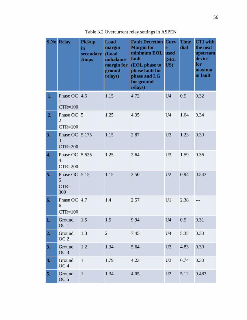
56
Table 3.2 Overcurrent relay settings in ASPEN
S.No Relay Pickup
in
secondary
Amps
Load
margin
(Load
unbalance
margin for
ground
relays)
Fault Detection
Margin for
minimum EOL
fault
(EOL phase to
phase fault for
phase and LG
for ground
relays)
Curv
e
used
(SEL
US)
Time
dial
CTI with
the next
upstream
device
for
maximu
m fault
1. Phase OC
1
CTR=100
4.6 1.15 4.72 U4 0.5 0.32
2. Phase OC
2
CTR=100
5 1.25 4.35 U4 1.64 0.34
3. Phase OC
3
CTR=200
5.175 1.15 2.87 U3 1.23 0.30
4. Phase OC
4
CTR=200
5.625 1.25 2.64 U3 1.59 0.36
5. Phase OC
5
CTR=
300
5.15 1.15 2.50 U2 0.94 0.543
6. Phase OC
6
CTR=100
4.7 1.4 2.57 U1 2.38 ---
1. Ground
OC 1
1.5 1.5 9.94 U4 0.5 0.31
2. Ground
OC 2
1.3 2 7.45 U4 5.35 0.30
3. Ground
OC 3
1.2 1.34 5.64 U3 4.83 0.30
4. Ground
OC 4
1 1.79 4.23 U3 6.74 0.30
5. Ground
OC 5
1 1.34 4.05 U2 5.12 0.483

57
Table 3.2 Overcurrent relay settings in ASPEN (Cont.)
6. Ground
OC 6
1 1.91 9.7125 U1 5.85 ---
7. Phase Inst
6
14.53 (1.3
times max
LS fault)
8. GND
INST 6
10.1 (1.3
times max
LS fault)
9. Phase Inst
4
17.584
(protects
85% of
line
instantane
ously)

58
Figure 3.18. TCC curves for ground overcurrent relay

59
Figure 3.19. TCC curves on the low side of the transformer coordinating with the
transformer damage curve drawn with respect to the low side 34.5 kV voltage

60
Figure 3.20. The TCC curve on the high side of the transformer coordinating with
the transformer damage curve drawn with respect to the high side 138 kV voltage

61
4. SETTING RELAY USING SEL 5030 SOFTWARE
4.1. CONFIGURATION SETTINGS
The Relay Identifier (RID) and Terminal Identifier (TID) settings typically are
used to identify the equipment protected by the relay or the identifier of the circuit
breakers controlled by the relay.
Relay identifier RID= XFMR 1
Terminal identifier TID = station A
Winding 1 and Winding 2 are enabled while winding 3 and winding 4 are
disabled for a two winding transformer. Also, Overcurrent elements for two transformer
windings are enabled.
E87W1=Y
E87W2=Y
E87W3= N
E87W4= N
EOC1=Y
EOC2 =Y
EOC3 =N
EOC4 =N
All other settings that are not used can be disabled by a selecting N
EOCC =N
ETHER =N
62
ELS1= N
ELS2 =N
4.2. GENERAL DATA
A 387-6 relay is used to protect a 80 MVA grounded wye-grounded wye 138/34.5
kV transformer. The CTs of both the windings are wye connected with the CTR on the
primary = 100 and the CTR on the secondary = 300.
W1CT=Y
W2CT=Y
CTR1 = 100
CTR 2= 300
MVA = 80
The internal compensation for the wye-wye transformer with a wye-wye CT can
be set to 12 to remove the zero sequence currents. However, selecting 12 may give
incorrect results for internal ground faults, so it is advisable to set the CT compensation
to 0 for both the windings for the purpose of experiments.
W1CTC = 0
W2CTC = 0
The voltages for winding 1 and 2 are 138kV and 34.5kV, respectively.
VWDG1 = 138
VWDG2 = 34.5

63
4.3. DIFFERENTIAL ELEMENT SETTINGS
The tap settings are automatically made by the relay based on the MVA.
Percent restraint slope settings:
087P = 0.3- Minimum pick up setting
SLP1 =25- Slope 1 setting
SLP2 =50- Slope 2 setting
IRS1 =3- restraint current slope 1 limit
U87P= 10- Unrestrained element pickup
The following settings relate to the harmonic blocking and harmonic restraint:
PCT2 = 15
PCT4 = 35
TH5P= OFF
IHBL= N
E32I= 0
4.4. OVERCURRENT ELEMENT SETTINGS
The overcurrent settings are calculated using the ASPEN model. All of the
settings are in secondary amperes. All of the negative sequence overcurrent elements
have been disabled (OFF) as they are not used. The torque control for all these
overcurrent elements can be set as 1 to make them trip without any external condition.
The SEL relay has 4 levels of instantaneous overcurrent elements. The level 1 elements
can be used for tripping by assigning the proper setting. The level 2 and level 3
instantaneous overcurrent elements can be used to unlatch trip by setting them as low as

64
0.5 A. It is important to set the level 4 phase instantaneous elements of both the windings
at their factory setting value of 4 A. OCA or OCB or OCC bits are monitored by
corresponding the 50Pn4 (phase instantaneous winding n level 4 element). For example,
relay word bit OCA indicates an A-phase overcurrent during the fault. It is derived by
first checking which winding “Wn” LED is lit, and then if the associated 50An4
overcurrent element bit is asserted, or if the magnitude of the IAWn phase current is
greater than or equal to the magnitudes of IBWn and ICWn. The same action is taken by
the OCB and OCC bits.
The winding 1 overcurrent element settings are
50P11P (winding 1 level 1 phase instantaneous element pickup) = 16.77
50P11D (winding 1 level 1 phase instantaneous element delay) = 0
50P11TC (winding 1 level 1 phase instantaneous element torque control) = 1
50P12P = 0.5 (used for unlatching)
50P13P = 0.5 (used for unlatching)
50P14P = 4
51P1P (winding 1 phase time overcurrent pickup) = 4.7
51P1C (winding 1 phase time curve) = U1
51P1TD (winding 1 phase time overcurrent dial) = 2.38
51P1RS (winding 1 phase time overcurrent electromechanic reset) = N
51P1TC (winding 1 phase time overcurrent torque control) = 1
50N11P (winding 1 level 1 ground instantaneous element pickup) = 11.65
50N11D (winding 1 level 1 ground instantaneous element delay) = 0
50N11TC (winding 1 level 1 ground instantaneous element torque control) = 1
65
50N12P = OFF
51N1P (winding 1 ground time overcurrent pickup) = 1
51N1C (winding 1 ground time curve) = U1
51N1TD (winding 1 ground time overcurrent dial) = 5.85
51N1RS (winding 1 ground time overcurrent electromechanic reset) = N
51N1TC (winding 1 ground time overcurrent torque control) = 1
The winding 2 overcurrent element settings are:
50P21P (winding 2 level 1 phase instantaneous element pickup) = OFF
50P22P = OFF
50P23P = 0.5 (Used for unlatching)
50P24P = 4
51P2P (winding 2 phase time overcurrent pickup) = 5.15
51P2C (winding 2 phase time curve) = U2
51P2TD (winding 2 phase time overcurrent delay) = 0.94
51P2RS (winding 2 phase time overcurrent electromechanic reset) = N
51P2TC (winding 2 phase time overcurrent torque control) = 1
50N21P (winding 2 level 1 ground instantaneous element pickup) = OFF
50N22P = OFF
51N2P (winding 2 ground time overcurrent pickup) = 1
51N2C (winding 2 ground time curve) = U2
51N2TD (winding 2 ground time overcurrent time dial) = 5.12
51N2RS (winding 2 ground time overcurrent electromechanic reset) = N
51N2TC (winding 2 ground time overcurrent torque control) = 1

66
4.5. TRIP EQUATIONS
Trip equations are used to set conditions for a breaker to trip. For the example
considered, first trip equation or Tr1 given by equation 4.1 is used to trip the breaker if
any of the winding 1 or winding 2 overcurrent elements assert. Second trip equation or
Tr2 given by equation 4.2 is used to trip a breaker if any of the restrained or unrestrained
differential elements assert. Tr2 asserts if either the differential restrained element or the
unrestrained element trips.
Tr1= 51P1T+51P2T (4.1)
Tr2=87U+87R (4.2)
4.6. UNLATCH TRIP EQUATIONS
A trip bit remains asserted until the unlatch trip bit asserts. The unlatch trip asserts
when the ultr1/ultr2 bit asserts or the target reset button on the relay front panel is
pushed. When the unlatch trip asserts, the trip bit drops.
ULTR1= !50P13
ULTR2= !50P23
The unlatch asserts when these word bit values drop below their settings, which is
usually assumed 0.5 Amps. The close and unlatch close logic can be left at their factory
settings as no breakers are wired to the relay outputs.
4.7. EVENT REPORT
The event report includes all the relay word bits that are included in the trip
equations. Equation 4.3 is used to generate event report. Event report is generated if any

67
of the differential relay bits 87U or 87R or any of the overcurrent relay bits 50P11 or
51P1 or 51P2 or 50N11 or 51N1 or 51N2 change from state ‘0’ to state ‘1’. The symbol
‘/’ in equation 4.3 indicates raising edge of a bit.
ER = /87U + /87R + /50P11 + /51P1 + /51P2 + /50N11 + /51N1+ /51N2 (4.3)
The length of an event report (LER) can be changed using the ‘SET G’ command.
The maximum limit for an LER is 60 cycles. The pre-fault event cycle ‘PRE’ setting is
also included in ‘SET G’ command. The pre-fault event cycle length can be any value
less than 60 cycles.
4.8. OUTPUT EQUATIONS
Each trip equation can be assigned to a particular output. The circuit breaker
contacts are usually wired to these output contacts:
OUT101= Tr1
OUT102=Tr2
4.9. SEL 387 RELAY SETTINGS- SCREEN SHOTS
Figure 4.1 and 4.2 are the screen shots of the settings in the SEL 5030 software.
The setting sreen appears after ‘SET 1’ ommand is typed. The following settings can be
left at their factory settings:
Demand metering elements
Miscellaneous timers

68
Figure 4.1. Screen shot of SEL 387 relay settings
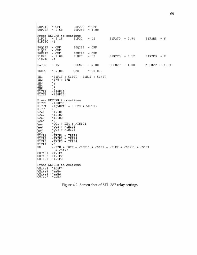
69
Figure 4.2. Screen shot of SEL 387 relay settings
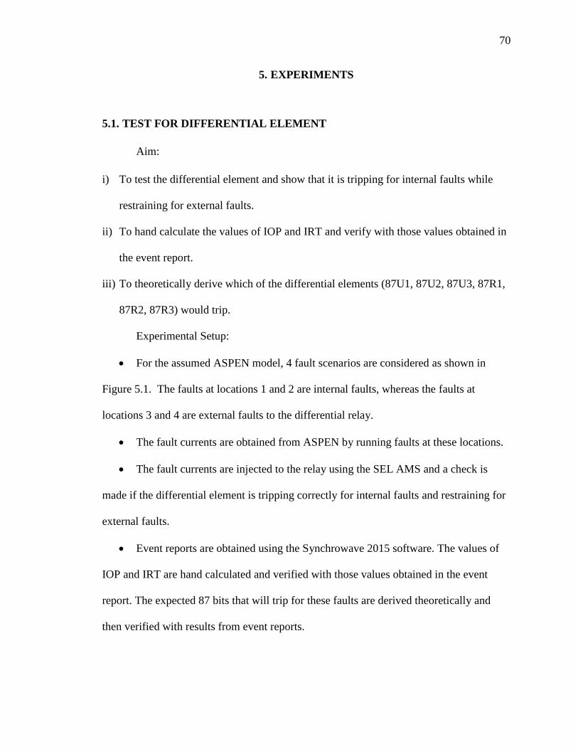
70
5. EXPERIMENTS
5.1. TEST FOR DIFFERENTIAL ELEMENT
Aim:
i) To test the differential element and show that it is tripping for internal faults while
restraining for external faults.
ii) To hand calculate the values of IOP and IRT and verify with those values obtained in
the event report.
iii) To theoretically derive which of the differential elements (87U1, 87U2, 87U3, 87R1,
87R2, 87R3) would trip.
Experimental Setup:
For the assumed ASPEN model, 4 fault scenarios are considered as shown in
Figure 5.1. The faults at locations 1 and 2 are internal faults, whereas the faults at
locations 3 and 4 are external faults to the differential relay.
The fault currents are obtained from ASPEN by running faults at these locations.
The fault currents are injected to the relay using the SEL AMS and a check is
made if the differential element is tripping correctly for internal faults and restraining for
external faults.
Event reports are obtained using the Synchrowave 2015 software. The values of
IOP and IRT are hand calculated and verified with those values obtained in the event
report. The expected 87 bits that will trip for these faults are derived theoretically and
then verified with results from event reports.

71
The following trip equations are used
Tr1= 51P1T+51P2T (5.1)
Tr2= 87U+87R (5.2)
Three Phase Fault At Location 1. A three phase fault is considered at
location 1 which is on primary side of transformer. The current phasors seen by the relays
on primary and secondary of transformer for this fault are shown in Figure 5.3. The pre
fault, fault and post fault currents in secondary amperes injected to the relay using SEL
AMS are shown in Figure 5.4. Figure 5.5 and Figure 5.6 are the event reports generated
for this fault. In Figure 5.5, the third waveform which indicates the changed relay word
bits by a solid blue line show that output contact OUT102 assigned to trip2 asserted as
relay bits 87R1, 87R2 and 87R3 have tripped. Tripping of 87R1, 87R2, 87R3 indicates
that the differential element’s restrained element picked up for a three phase fault.
Differential event report in Figure 5.6 gives information about operate current and
restrained current magnitudes for all three phases during fault.
From Figure 5.6,
IOP1= 5.4, IOP2 = IOP3= 5.38
IRT1= IRT2= 2.7, IRT3 = 2.69
Figure 5.1. Four fault scenarios considered for experiment

72
Theoretical calculations:
IAW1 18.05 83.3I1W1C1= = = 5.38 83.3
TAP1 3.35
IBW1 18.05 156.7I2W1C1= 5.38 156.7
TAP1 3.35
ICW1 18.05 36.7I3W1C1= = = 5.38 36.7
TAP1 3.35
IAW2I1W2C1= = 0
TAP2
IBW2I2W2C1= 0
TAP2
ICW2I3W2C1= = 0
TAP2
IOP1= I1W1C1+ I1W2C1 5.38 83.3 0 5.38
IOP2= I2W1C1+ I2W2C1 5.38 156.7 0 5.38
IOP3= I3W1C1+ I3W2C1 5.38 36.7 0 5.38
I1W1C1 + I1W2C1 5.38 -83.3 0IRT1= 2.69
2 2
I2W1C1 + I2W2C1 5.38 156.7 0IRT2= 2.69
2 2
I3W1C1 + I3W2C1 5.38 36.7 0IRT3= 2.69
2 2
Implementation of differential logic:
Minimum pickup 087P intersects slope 1 at the value of restraint current given by
087P*100 0.3*100IRT = = 1.2
SLP1 25

73
Since 1.2 < (IRT1 = IRT2 = IRT3 = 2.69), from Section 3.4, case 3 can be applied to
determine which of the differential elements would trip:
Condition 1: IOP1 IOP2 IOP3
( = = ) = 0.5 > (SLP1 = 0.25)IRT1 IRT2 IRT3
Condition 2: (IOP1 = IOP2= IOP3 = 5.38) > (087P = 0.3)
Hence the differential restrained elements 87R1, 87R2, 87R3 elements are
expected to trip. The approximate operating point is marked 1 in Figure 5.2.
Phase To Phase Fault At Location 2. A phase to phase fault is considered
at location 2 or on secondary side of transformer. The current phasors seen by the relays
on primary and secondary of transformer for this fault are shown in Figure 5.7. The pre
fault, fault and post fault currents in secondary amperes injected to the relay using SEL
AMS are shown in Figure 5.8. Figure 5.9 and Figure 5.10 are the event reports generated
for this fault. In Figure 5.9, the third waveform which indicates the changed relay word
bits by a solid blue line show that output contact OUT102 assigned to trip2 asserted as
relay bits 87R2 and 87R3 have tripped. Tripping of 87R2, 87R3 indicates that the
differential element’s restrained element picked up for a phase B to C fault. Differential
event report in Figure 5.10 gives information about magnitudes of operate and restrained
currents for all three phases during fault.
From figure 5.10,
IOP1= 0, IOP2 = 3.04, IOP3= 3.01
IRT1=0, IRT2= 1.52, IRT3 = 1.51
Theoretical Calculations:
IAW1I1W1C1= = 0
TAP1

74
IBW1 10.19 168.2I2W1C1= 3.04 168.2
TAP1 3.35
ICW1 10.07 22.4I3W1C1= = = 3 22.4
TAP1 3.35
I1W2C1= I2W2C1 I3W2C1= 0
IOP1=0
IOP2= I2W1C1+ I2W2C1
= 3.04 pu
IOP3= I3W1C1+ I3W2C1
= 3 pu
IRT1= 0 pu
I2W1C1 + I2W2C1IRT2=
2
= 1.52
I3W1C1 + I3W2C1IRT3=
2
= 1.5 pu
Implementation of differential logic:
Minimum pickup intersects slope 1 at the value of restraint current given by
087P*100 0.3*100IRT= = 1.2
SLP1 25
Since 1.2 < (IRT2 = IRT3 = 1.52), from Section 3.4, case 3 can be applied to determine
which of the differential elements would trip:

75
Condition 1: IOP2 IOP3
( = = 0.5) > (SLP1 = 0.25)IRT2 IRT3
Condition 2: (IOP2= 3.04, IOP3 = 3) > (087P = 0.3)
Hence the differential relay restrained elements 87R2, 87R3 elements are
expected to trip. The approximate operating point is marked 2 in Figure 5.2.
Three Phase Fault At Location 3. A three phase fault is considered at
location 3 which is external to transformer. The current phasors seen by the relays on
primary and secondary of transformer for this fault are shown in Figure 5.11. The pre
fault, fault and post fault currents in secondary amperes injected to the relay using SEL
AMS are shown in Figure 5.12. Figure 5.13, Figure 5.14 and Figure 5.15 are the event
reports generated for this fault. In Figure 5.13, changed relay word bits indicated by solid
blue line show that winding 1 phase time overcurrent element 51P1 and winding 2 phase
time overcurrent element 51P2 picked up. In Figure 5.14, the third waveform shows that
output contact OUT101 assigned to trip1 asserted as relay bit 51P2T tripped and
differential element restrained. Tripping of OCA (phase A overcurrent), OCB (phase B
overcurrent), OCC (phase C overcurrent), indicates that overcurrent elements of phase
A,B,C tripped. Differential event report in Figure 5.15 gives information about the
magnitudes of operate and restrained currents for all three phases during fault.
From Figure 5.15,
IOP1= IOP2 = IOP3= 0
IRT1= IRT2= IRT3 = 3.34
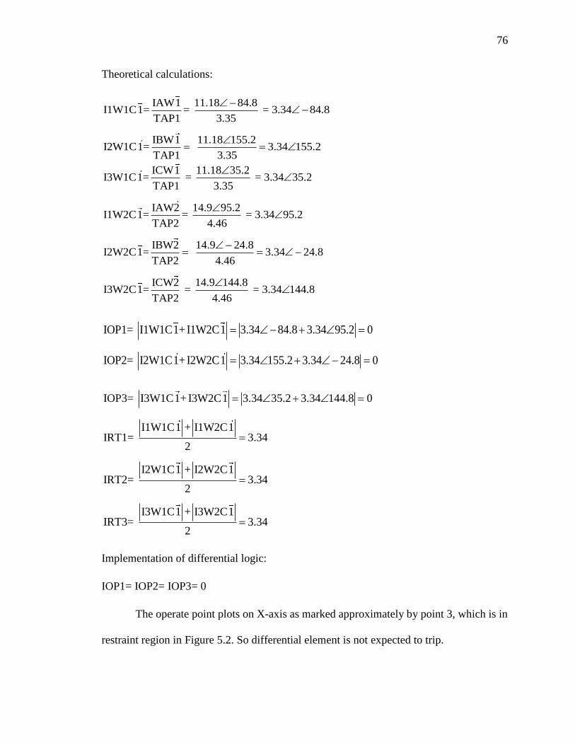
76
Theoretical calculations:
IAW1 11.18 84.8I1W1C1= = = 3.34 84.8
TAP1 3.35
IBW1 11.18 155.2I2W1C1= 3.34 155.2
TAP1 3.35
ICW1 11.18 35.2I3W1C1= = = 3.34 35.2
TAP1 3.35
IAW2 14.9 95.2I1W2C1= = = 3.34 95.2
TAP2 4.46
IBW2 14.9 24.8I2W2C1= 3.34 24.8
TAP2 4.46
ICW2 14.9 144.8I3W2C1= = = 3.34 144.8
TAP2 4.46
IOP1= I1W1C1+ I1W2C1 3.34 84.8 3.34 95.2 0
IOP2= I2W1C1+ I2W2C1 3.34 155.2 3.34 24.8 0
IOP3= I3W1C1+ I3W2C1 3.34 35.2 3.34 144.8 0
I1W1C1 + I1W2C1IRT1= 3.34
2
I2W1C1 + I2W2C1IRT2= 3.34
2
I3W1C1 + I3W2C1IRT3= 3.34
2
Implementation of differential logic:
IOP1= IOP2= IOP3= 0
The operate point plots on X-axis as marked approximately by point 3, which is in
restraint region in Figure 5.2. So differential element is not expected to trip.

77
Phase To Phase Fault At Location 4. A phase to phase (B to C phase)
fault is considered at location 4 which is external to transformer. The current phasors
seen by the relays on primary and secondary of transformer for this fault are shown in
Figure 5.16. The pre fault, fault and post fault currents in secondary amperes injected to
the relay using SEL AMS are shown in Figure 5.17. Figure 5.18, Figure 5.19 and Figure
5.20 are the event reports generated for this fault. In Figure 5.18, changed relay word bits
indicated by solid blue line show that winding 1 phase time overcurrent element 51P1
and winding 2 phase time overcurrent element 51P2 picked up. In Figure 5.19, the third
waveform shows that output contact OUT101 assigned to trip1 asserted as relay bit
51P2T tripped and differential element restrained. Tripping of OCB, OCC, indicates that
overcurrent elements of phase B,C tripped. Differential event report in Figure 5.20 gives
information about magnitudes of operate and restrained currents for all three phases
during fault.
From Figure 5.20,
IOP1= IOP2 = IOP3= 0
IRT1= IRT2= IRT3 = 2.22
Theoretical calculations:
IAW1I1W1C1= =0
TAP1
IBW1 7.43 170.8I2W1C1= 2.22 170.8
TAP1 3.35
ICW1 7.43 9.1I3W1C1= = 2.22 9.1
TAP1 3.35

78
IAW2I1W2C1= = 0
TAP2
IBW2 9.91 9.2I2W2C1= 2.22 9.2
TAP2 4.46
ICW2 9.91 170.8I3W2C1= = 2.22 170.8
TAP2 4.46
IOP1= I1W1C1+ I1W2C1 0
IOP2= I2W1C1+ I2W2C1 2.22 170.8 2.22 9.2 0
IOP3= I3W1C1+ I3W2C1 2.22 9.1 2.22 170.8 0
I1W1C1 + I1W2C1IRT1= 2.22
2
I2W1C1 + I2W2C1IRT2= 2.22
2
IR
I3W1C1 + I3W2C1T3= 2.22
2
Implementation of differential logic:
IOP1= IOP2= IOP3= 0
The point plots on X-axis as marked approximately by point 4 in Figure 5.2. So
differential element is not expected to trip.
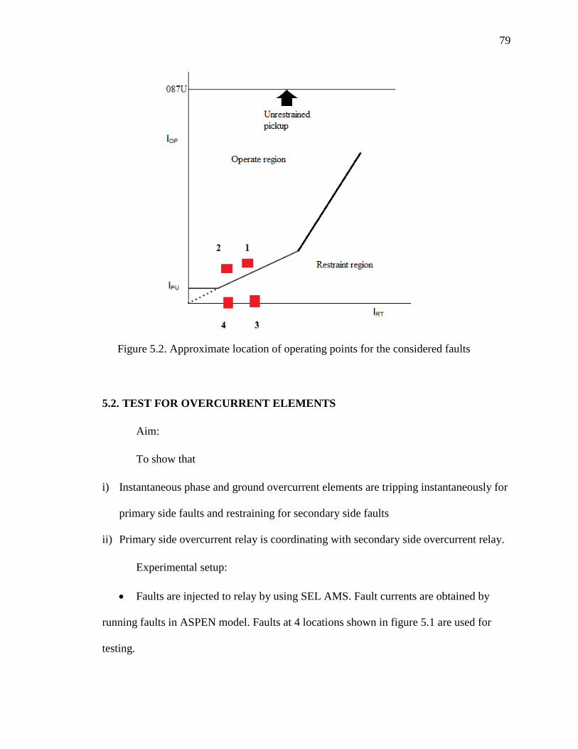
79
5.2. TEST FOR OVERCURRENT ELEMENTS
Aim:
To show that
i) Instantaneous phase and ground overcurrent elements are tripping instantaneously for
primary side faults and restraining for secondary side faults
ii) Primary side overcurrent relay is coordinating with secondary side overcurrent relay.
Experimental setup:
Faults are injected to relay by using SEL AMS. Fault currents are obtained by
running faults in ASPEN model. Faults at 4 locations shown in figure 5.1 are used for
testing.
Figure 5.2. Approximate location of operating points for the considered faults

80
The phase instantaneous elements are tested by running three phase, phase to
phase faults on primary side and three phase fault on secondary side of transformer.
Ground instantaneous element is tested by running line to ground fault on primary and
secondary sides of transformer.
Coordination of primary side phase time overcurrent relay with secondary side
phase time overcurrent relay is verified by injecting three phase fault currents to relay.
Coordination of primary side ground time overcurrent relay with secondary side ground
time overcurrent relay is verified by injecting single line to ground fault currents to relay.
The following trip equations are used
Tr1= 51P1T+51N1T+51N2T+51P2T (5.3)
Tr2= 50N11T+50P11T (5.4)
Three Phase Fault At Location 1. A three phase fault is considered at
location 1 which is on the primary of transformer. The current phasors seen by the relays
on primary and secondary of transformer for this fault are shown in Figure 5.3. The pre
fault, fault and post fault currents in secondary amperes injected to the relay using SEL
AMS are shown in Figure 5.4. Figure 5.21, is the event report generated for this fault. In
Figure 5.21, changed relay word bits indicated by solid blue line show that phase
instantaneous winding 1 overcurrent 50P11T element tripped, OUT102 assigned to trip2
asserted as relay bit 50P11T tripped. Tripping of OCA, OCB, OCC indicates that
overcurrent elements of phases A, B,C tripped.
Phase To Phase Fault At Location 1. A phase to phase fault is considered
at location 1 which is on the primary of transformer. The current phasors seen by the
relays on primary and secondary of transformer for this fault are shown in Figure 5.22.

81
The pre fault, fault and post fault currents in secondary amperes injected to the relay
using SEL AMS are shown in Figure 5.23. Figure 5.24 is the event report generated for
this fault. In Figure 5.24, changed relay word bits indicated by solid blue line shows that
phase instantaneous winding 1 overcurrent 50P11T element tripped, OUT102 assigned to
trip2 asserted as relay bit 50P11T tripped. Tripping of OCB, OCC indicates that
overcurrent elements of phases B,C tripped.
Three Phase Fault At Location 2. A three phase fault is considered at
location 2 which is on the secondary of transformer. The current phasors seen by the
relays on primary and secondary of transformer for this fault are shown in Figure 5.25.
The pre fault, fault and post fault currents in secondary amperes injected to the relay
using SEL AMS are shown in Figure 5.26. Figure 5.27 and Figure 5.28 are the event
reports generated for this fault. In Figure 5.27, changed relay word bits indicated by solid
blue line show that winding 1 phase time overcurrent element (51P1) picked up. In
Figure 5.28, the third waveform shows that output contact OUT101 assigned to trip1
asserted as relay bit 51P1T or winding 1 phase time overcurrent element tripped.
Tripping of OCA, OCB, OCC, indicates that overcurrent elements of phases A, B,C
tripped.
Three Phase Fault At Location 3. A three phase fault is considered at
location 3. The current phasors seen by the relays on primary and secondary of
transformer for this fault are shown in Figure 5.11. The pre fault, fault and post fault
currents in secondary amperes injected to the relay using SEL AMS are shown in Figure
5.12. Figure 5.29, Figure 5.30 are the event reports generated for this fault. In Figure
5.29, changed relay word bits indicated by solid blue line show that winding 1 phase time

82
overcurrent element 51P1 and winding 2 phase time overcurrent element 51P2 picked up.
In Figure 5.30, the third waveform shows that output contact OUT101 assigned to trip1
asserted as relay bit 51P2T tripped. Tripping of OCA, OCB, OCC indicates that
overcurrent elements of phase A,B,C tripped.
Three Phase Fault At Location 4. A three phase fault is considered at
location 4. The current phasors seen by the relays on primary and secondary of
transformer for this fault are shown in Figure 5.31. The pre fault, fault and post fault
currents in secondary amperes injected to the relay using SEL AMS are shown in Figure
5.32. Figure 5.33, Figure 5.34 are the event reports generated for this fault. In Figure
5.33, changed relay word bits indicated by solid blue line show that winding 1 phase time
overcurrent element 51P1 and winding 2 phase time overcurrent element 51P2 picked up.
In Figure 5.34, the third waveform shows that output contact OUT101 assigned to trip1
asserted as relay bit 51P2T or winding 2 phase time overcurrent element tripped.
Tripping of OCA, OCB, OCC indicates that overcurrent elements of phase A,B,C
tripped.
Single Line To Ground Fault At Location 1. A single line to ground fault
is considered at location 1 which is on the primary of transformer. The current phasors
seen by the relays on primary and secondary of transformer for this fault are shown in
Figure 5.35. The pre fault, fault and post fault currents in secondary amperes injected to
the relay using SEL AMS are shown in Figure 5.36. Figure 5.37 is the event report
generated for this fault. In Figure 5.37, changed relay word bits indicated by solid blue
line shows that instantaneous winding 1 ground overcurrent element 50N11T tripped,

83
OUT102 assigned to trip2 asserted as relay bit 50N11T tripped. Tripping of OCA
indicates that overcurrent element of phase A tripped.
Single Line To Ground Fault At Location 2. A single line to ground fault
is considered at location 2 which is on the secondary of transformer. The current phasors
seen by the relays on primary and secondary of transformer for this fault are shown in
Figure 5.38. The pre fault, fault and post fault currents in secondary amperes injected to
the relay using SEL AMS are shown in Figure 5.39. Figure 5.40 and Figure 5.41 are the
event reports generated for this fault. In Figure 5.40, changed relay word bits indicated by
solid blue line show that winding 1 ground time overcurrent element 51N1 picked up. In
Figure 5.41, the third waveform shows that output contact OUT101 assigned to trip1
asserted as relay bit 51N1T tripped and differential element restrained. Tripping of OCA
indicates that overcurrent element of phase A tripped.
Single Line To Ground Fault At Location 3. A single line to ground fault
is considered at location 3. The current phasors seen by the relays on primary and
secondary of transformer for this fault are shown in Figure 5.42. The pre fault, fault and
post fault currents in secondary amperes injected to the relay using SEL AMS are shown
in Figure 5.43. Figure 5.44 and Figure 5.45 are the event reports generated for this fault.
In Figure 5.44, changed relay word bits indicated by solid blue line show that winding 1
ground time overcurrent (51N1) and winding 2 ground time overcurrent (51N2) elements
picked up. In Figure 5.45, the third waveform shows that output contact OUT101
assigned to trip1 asserted as relay bit 51N2T tripped. Tripping of OCA indicates that
overcurrent element of phase A tripped.

84
Single Line To Ground Fault At Location 4. A single line to ground fault
is considered at location 4. The current phasors seen by the relays on primary and
secondary of transformer for this fault are shown in Figure 5.46. The pre fault, fault and
post fault currents in secondary amperes injected to the relay using SEL AMS are shown
in Figure 5.47. Figure 5.48 and Figure 5.49 are the event reports generated for this fault.
In Figure 5.48, changed relay word bits indicated by solid blue line show that winding 1
ground time overcurrent (51N1) and that winding 2 ground time overcurrent (51N2)
elements picked up. In Figure 5.49, the third waveform shows that output contact
OUT101 assigned to trip1 asserted as relay bit 51N2T tripped. Tripping of OCA indicates
that overcurrent element of phase A tripped.

85
Figure 5.3. Fault currents obtained from ASPEN for three phase fault at location 1
Figure 5.4. SEL AMS setting for three phase fault at location 1

86
Figure 5.6. Differential event report for three phase fault at location 1
Figure 5.5. Event report for three phase fault at location 1

87
Figure 5.8. SEL AMS setting for phase to phase fault at location 2
Figure 5.7. Fault currents obtained from ASPEN for phase to phase fault at location 2

88
Figure 5.9. Event report for phase to phase fault at location 2
Figure 5.10. Differential event report for phase to phase fault at location 2

89
Figure 5.11. Fault currents obtained from ASPEN for a three phase fault at location 3
Figure 5.12. SEL AMS setting for three phase fault at location 3

90
Figure 5.13. Event report showing pickup of relay bits for a three phase fault at
location 3

91
Figure 5.14. Event report showing tripping of overcurrent element for three phase fault
at location 3
Figure 5.15. Differential event report for three phase fault at location 3
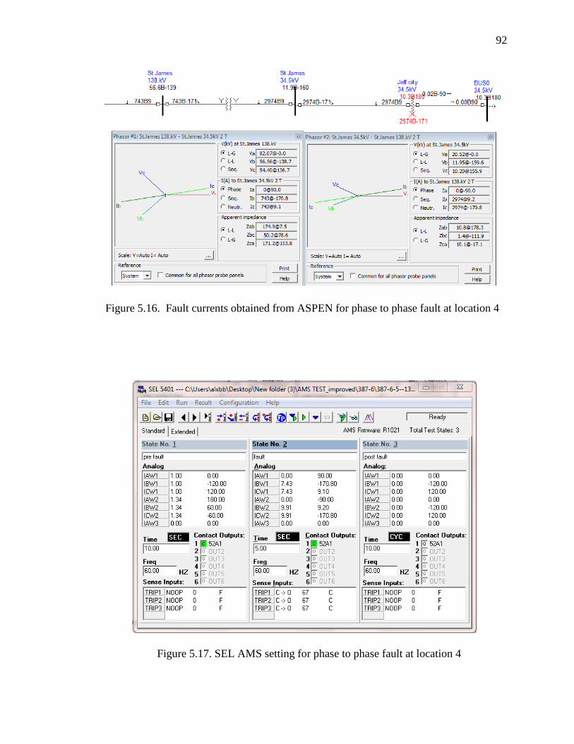
92
Figure 5.16. Fault currents obtained from ASPEN for phase to phase fault at location 4
Figure 5.17. SEL AMS setting for phase to phase fault at location 4

93
Figure 5.18. Event report showing pickup of overcurrent element for phase to phase
fault at location 4

94
Figure 5.19. Event report showing tripping of overcurrent element for phase to phase
fault at location 4
Figure 5.20. Differential event report for phase to phase fault at location 4

95
Figure 5.21. Event report showing tripping of overcurrent element for three phase fault
at location 1

96
Figure 5.22. Fault currents obtained from ASPEN for phase to phase fault at location 1
Figure 5.23. SEL AMS setting for phase to phase fault at location 1

97
Figure 5.24. Event report showing tripping of overcurrent element for phase to phase
fault at location 1
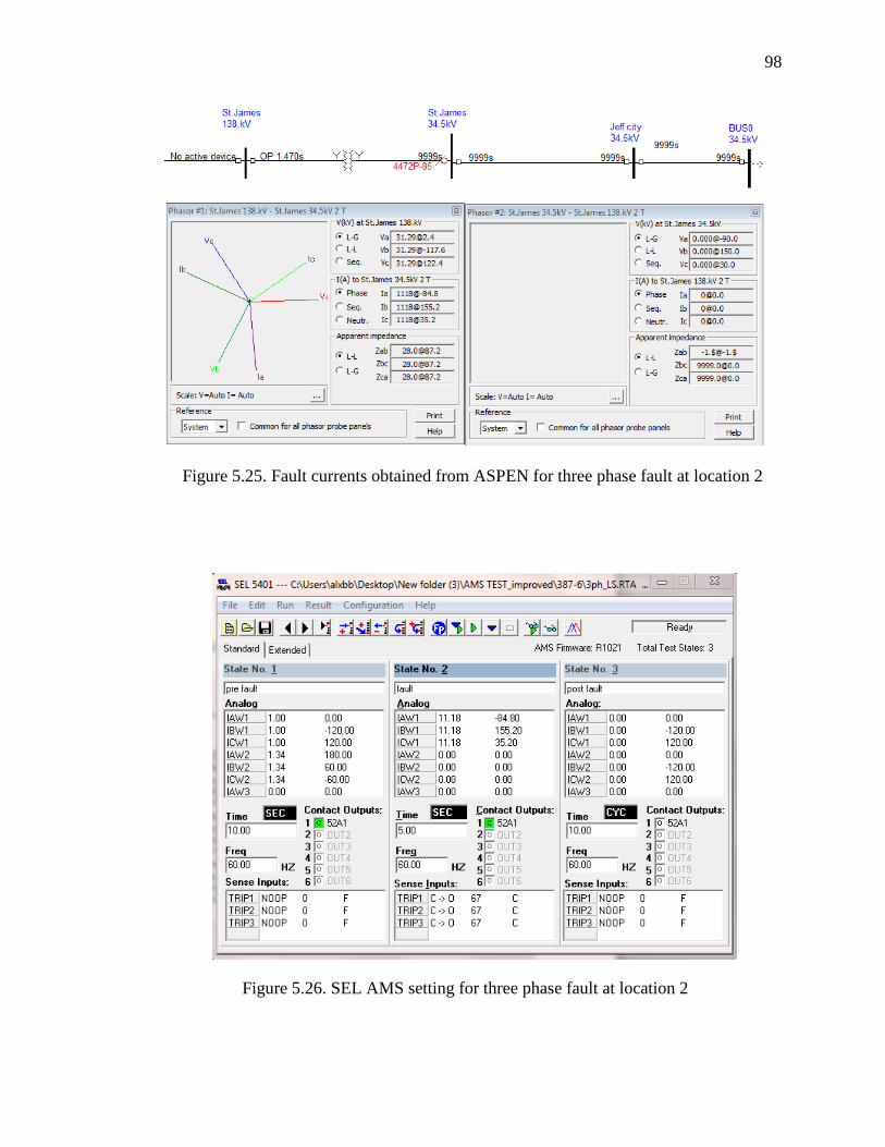
98
Figure 5.25. Fault currents obtained from ASPEN for three phase fault at location 2
Figure 5.26. SEL AMS setting for three phase fault at location 2
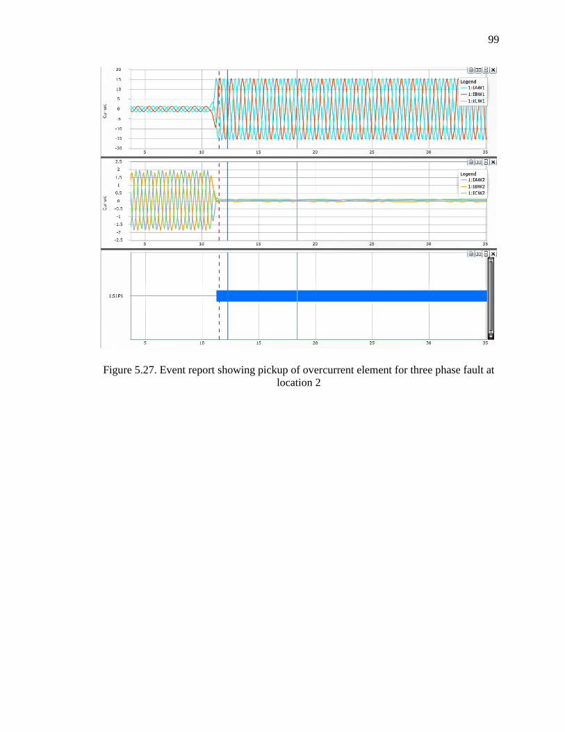
99
Figure 5.27. Event report showing pickup of overcurrent element for three phase fault at
location 2

100
Figure 5.28. Event report showing tripping of overcurrent element for three phase fault
at location 2

101
Figure 5.29. Event report showing pickup of overcurrent element for three phase fault at
location 3

102
Figure 5.30. Event report showing tripping of overcurrent element for three phase fault at
location 3

103
Figure 5.31. Fault currents obtained from ASPEN for three phase fault at location 4
Figure 5.32. SEL AMS setting for three phase fault at location 4

104
Figure 5.33. Event report showing pickup of overcurrent element for three phase fault at
location 4

105
Figure 5.34. Event report showing tripping of overcurrent element for three phase fault
at location 4

106
Figure 5.35. Fault currents obtained from ASPEN for single line to ground fault at
location 1
Figure 5.36. SEL AMS setting for single line to ground fault at location 1

107
Figure 5.37. Event report showing tripping of ground overcurrent element for single line
to ground fault at location 1
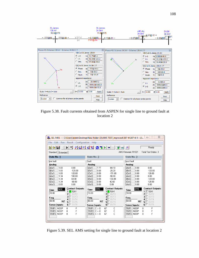
108
Figure 5.38. Fault currents obtained from ASPEN for single line to ground fault at
location 2
Figure 5.39. SEL AMS setting for single line to ground fault at location 2

109
Figure 5.40. Event report showing pickup of ground overcurrent element for single line
to ground fault at location 2

110
Figure 5.41. Event report showing tripping of ground overcurrent element for single
line to ground fault at location 2

111
Figure 5.42. Fault currents obtained from ASPEN for single line to ground fault at
location 3
Figure 5.43. SEL AMS setting for single line to ground fault at location 3

112
Figure 5.44. Event report showing pickup of ground overcurrent element for single line
to ground fault at location 3

113
Figure 5.45. Event report showing tripping of ground overcurrent element for single line
to ground fault at location 3

114
Figure 5.46. Fault currents obtained from ASPEN for single line to ground fault at
location 4
Figure 5.47. SEL AMS setting for single line to ground fault at location 4
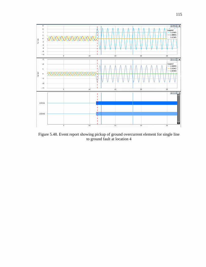
115
Figure 5.48. Event report showing pickup of ground overcurrent element for single line
to ground fault at location 4

116
Figure 5.49. Event report showing tripping of ground overcurrent element for single line
to ground fault at location 4

APPENDIX A- GETTING STARTED WITH ACSELERATOR QUICKSET
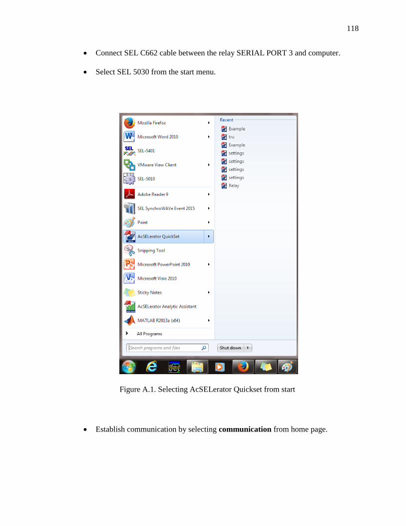
118
Connect SEL C662 cable between the relay SERIAL PORT 3 and computer.
Select SEL 5030 from the start menu.
Figure A.1. Selecting AcSELerator Quickset from start
Establish communication by selecting communication from home page.

119
Select the parameters as shown in Figure A.3 for the SEL 387-6 relay. The
password fields can be left empty. Communication will be established within few
seconds.
Figure A.2. AcSELerator Quickset home page

120
Figure A.3. Communication Parameters

121
Click on terminal icon on the menu bar or type ctrl+T to open the work space
used to program the relay.
A terminal window gets opened. Use the password ‘power’ for level 1. All the
relay commands need to access level 2. To go to access level 2 type ‘2acc<enter>’. The
password is ‘power’.
Type ‘set 1’ to begin programming the relay.
Figure A.4. ‘Terminal’ option highlighted on the menubar
Figure A.5. Terminal window

APPENDIX B- SEL AMS SETUP

123
Connect the C750 ribbon cable from SEL 387-6 to the analog output of the SEL
AMS. Connect the SEL C662 serial cable between the AMS and computer. These
connections are shown in Figure B.1.
Turn the relay ON. Plug in the SEL AMS power cable. Make sure that DC supply
and main supply LEDs are ON.
Select SEL- 5401 from the start menu.
Figure B.1. Image showing connections of SEL AMS to SEL 387 relay

124
Select New from the topmost menu bar.
Figure B.2. ‘SEL-5401’ option under start
option
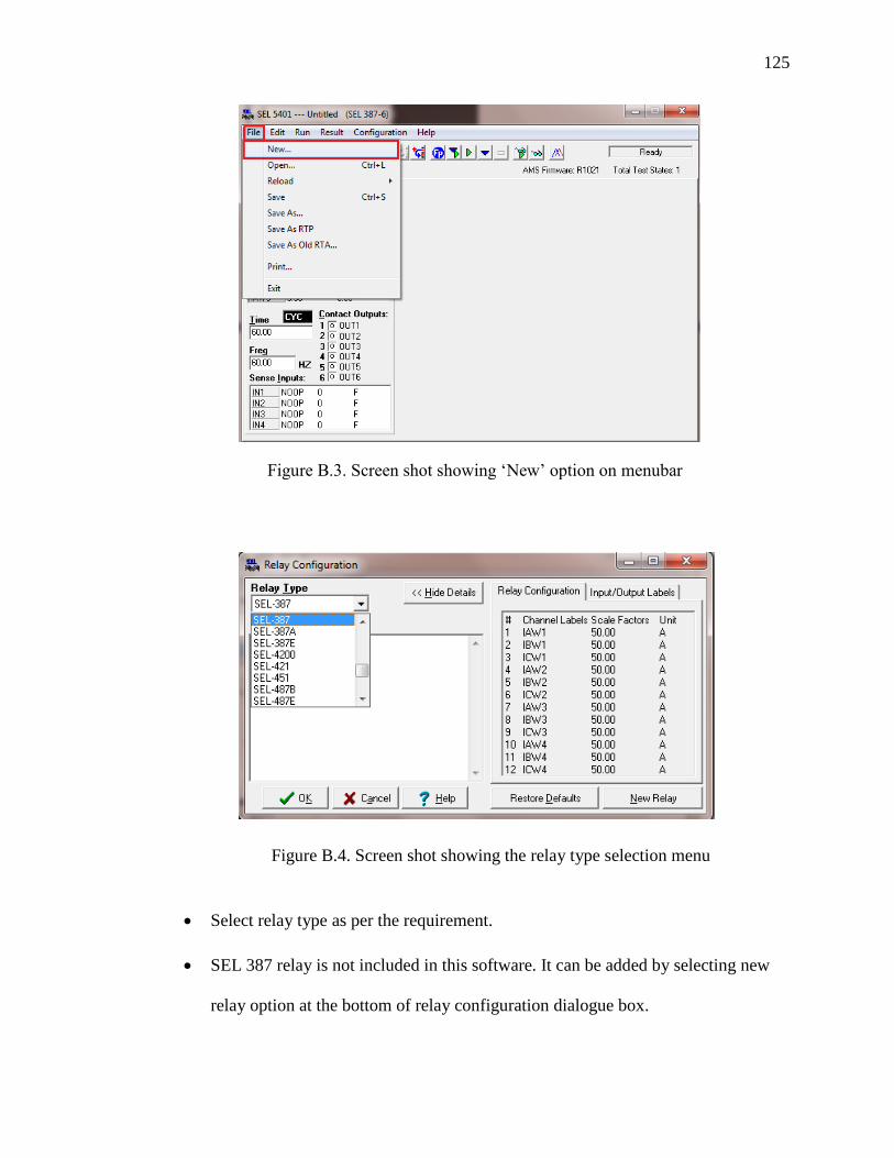
125
Select relay type as per the requirement.
SEL 387 relay is not included in this software. It can be added by selecting new
relay option at the bottom of relay configuration dialogue box.
Figure B.3. Screen shot showing ‘New’ option on menubar
Figure B.4. Screen shot showing the relay type selection menu

126
Assign the relay name as SEL 387-6.
Assign the appropriate labels, scale factors, and units.
Labels can be found at the back of relay.
Figure B.6. Screen shot of rear view of relay showing labels [5]
Figure B.5. Space area in SEL 5401 software to enter the configuration settings for a
new relay

127
The scale factors can be obtained from relay input module. This is available in
SEL 387 manual under Chapter 10 “Testing and trouble shooting.”
Figure B.7. Screen shot from SEL 387-6 manual showing scale factors
The scale factor = 5A/100mV = 50 for this particular relay.
B.1. SEL AMS TEST SETTINGS
Setting SEL AMS requires the settings for pre-fault, fault and post fault
conditions
B.1.1. Pre-fault state. Enter the state name as pre fault
Enter the winding 1 (primary) and winding 2 (secondary) pre fault current
phasors. The magnitudes of primary and secondary currents can be chosen as low as 1
ampere and 1.34 (1*CTR of primary*transformer turns ratio/CTR of secondary winding)
amperes respectively in secondary amperes.
The currents in winding 1 will be going into the line and currents in winding 2
will be going out of line. Hence, for a grounded wye-grounded wye transformer there
exists 180˚ phase shift between primary and secondary currents. So, phase angles of

128
primary currents are 0, -120˚,+120˚ and secondary currents are 180˚, 60˚, -60˚
respectively for phases A, B, C. If there is a 30˚ delta wye phase shift between primary
and secondary and if the primary delta winding leads secondary wye winding by 30˚, the
phase angles of secondary currents will be 150˚, 30˚, -90˚ when the phase angles of
primary currents are 0, -120˚,+120˚ respectively for phases A, B, C.
Time of pre fault state can be set for 10 seconds.
Set the contact outputs to closed or ‘c’ state. This change can be done using the
space bar.
Leave the sense inputs at NOOP or no operation state
B.1.2. Fault state. Enter the state name as fault
Convert the currents obtained from ASPEN phasors into secondary currents for
winding 1 and winding 2 by dividing each of them by corresponding CT ratios.
Select the time in the range of 5 to 60 cycles if instantaneous operation
(Instantaneous element or differential element trip) is expected. Otherwise if the relay is
expected to trip in few seconds after it has picked up, select the time in the range of 3 to
10 seconds.
Frequency is selected as 60 Hertz
Contact output status is set as C or closed. If needed this can be changed to open
by using spacebar on keyboard
Set the sense inputs function as CO, set delay as 67ms, TOS as C.
B.1.3. Post fault. Enter the state name as Post fault
Assign 0 currents to all windings
A 10 – 20 cycles time can be assigned

129
Set the contact inputs as open
Set the frequency as 60 Hertz
Leave the sense inputs at NOOP or no operation state
To run a test, select ‘Download and run this test’ icon from the menu bar.
Figure B.8. Pre fault state for a delta wye transformer with primary side leading
secondary side by 30˚

130
Figure B.9. Screen shot of pre fault, fault and post fault states entered into SEL
5401 software

APPENDIX C- PROCEDURE TO RETRIEVE EVENT REPORTS FROM RELAY

132
From menu bar select events get event files
Select the type of event. If a differential event report is required, select 8
samples/cycle-differential option. For a common type event report select any other
option. Enter the length of the event report as required. Maximum event length is 60
cycles.
Figure C.1. Screen shot of AcSELerato Quickset screen to get event files
Figure C.2. Screen shot showing list of event types in AcSELerator Quickset
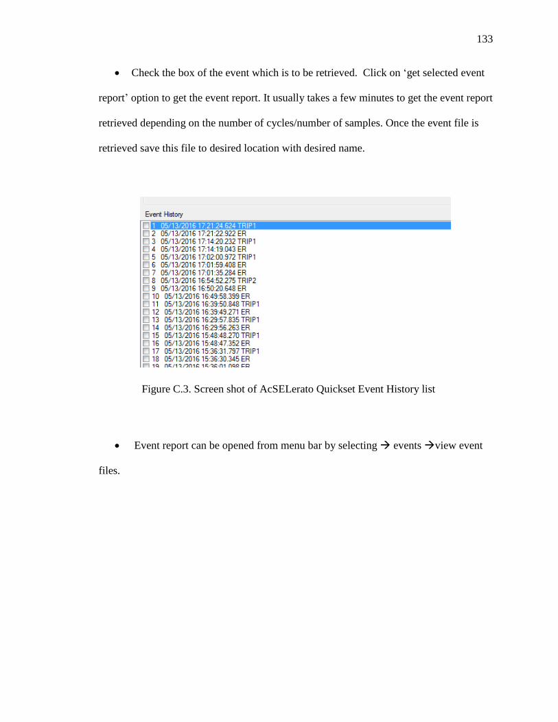
133
Check the box of the event which is to be retrieved. Click on ‘get selected event
report’ option to get the event report. It usually takes a few minutes to get the event report
retrieved depending on the number of cycles/number of samples. Once the event file is
retrieved save this file to desired location with desired name.
Event report can be opened from menu bar by selecting events view event
files.
Figure C.3. Screen shot of AcSELerato Quickset Event History list

134
C.1. ANALYSIS OF DIFFERENTIAL EVENT REPORTS
Figures C.5 and C.6 show sample differential event reports. Figure C.5 shows the
waveforms of operate currents IOP1, IOP2, IOP3 for phase A, B, C respectively and
restraint currents IRT1, IRT2, IRT3 for phase A, B, C respectively. The peak value of
graphs represents the operate current and restraint current magnitudes during faults.
In Figure C.6 changed relay word bits are indicated by a solid blue line. For
example, the solid blue line next to 87R indicates that differential restraint element
tripped during a fault event. Similarly, solid blue line next to trip2 indicates that trip2 bit
asserted.
Figure C.4. Screen shot of AcSELerato Quickset screen to view event files

135
C.2. ANALYSIS OF RAW/FILTERED EVENT REPORTS
This discussion applies to any type of raw/filtered event report with any number of
samples per cycle.
Figure C.5. Differential event report showing the waveforms of operate
and restraint currents
Figure C.6. Differential event report showing changed relay bits when a
differential element tripped

136
Case 1: When the tripping is instantaneous
Differential element 87 or instantaneous element 50 will trip instantaneously with
a time delay of less than 5 cycles. There is a 60 cycle limit to the length of event report.
Because it takes less than 5 cycles to trip for these elements, the event reports can clearly
show pre fault, fault and post fault states within this 60 cycles span. In Figure C.7, the
upper wave form represents winding 1 or transformer primary current waveform. The
lower wave form is winding 2 or transformer secondary current waveform. Figure C.8
shows the changed digitals or relay bits during relay operation. This active digitals
column gives information about both picked up relay bits as well as tripped relay bits. For
instance, in Figure C.8, 50P11 and 51P1 represents relay bits which picked up while
50P11T, OCB, OCC, OUT102, TRIP2 represents relay bits which were asserted or have
changed to state ‘1’. It is not necessary for all the picked up bits to assert to ‘1’. For
instance, in the same example, the 51P1 relay bit picked up but did not assert because the
fault condition subsided before the time delay associated with this relay bit got expired.
The dotted red line indicates the time at which a particular relay bit has picked up. The
blue vertical line is a data line which can be moved anywhere to get the magnitude of
current at that particular point.

137
Case 2: Time overcurrent elements
For time overcurrent elements two event reports are generated. The first event
report gives information about the relay word bits or elements which picked up. The
second event report gives information about the elements which got asserted or reached
state ‘1’. Figures C.9 and C.10 shows sample event reports for overcurrent elements
which have tripped with a time delay.
Figure C.8. Event report showing changed relay bits for a phase to phase fault
Figure C.7. Event report showing transformer primary and secondary currents

138
Figure C.9. Event report showing pickup of ground overcurrent element for
single line to ground fault

139
Figure C.10. Event report showing tripping of ground overcurrent element for single
line to ground fault

140
REFERENCES
[1] J. Lewis Blackburn and Thomas J Domin, Protective Relaying: Principles and
Applications, 3rd edition, New York: CRC Press,2006.
[2] J. Duncan Glover, Mulukutla S. Sarma, Thomas Overbye, Power System Analysis
and Design, 5th edition, Cengage Learning, 2011.
[3] Micheal J Thompson, “Percentage Restrained Differential, Percentage of What?”
Schweitzer Engineering Laboratories, Inc., https://selinc.com/literature/technical-
papers/. Presented at WPRC 2010, Texas A&M Relay Conference 2011.
[4] Ken Behrendt, Normann Fischer, and Casper Labuschagne, “Considerations for
Using Harmonic Blocking and Harmonic Restraint Techniques on Transformer
Differential Relays.” Schweitzer Engineering Laboratories, Inc.,
https://selinc.com/literature/technical-papers/. Presented at WPRC 2006,
MIPSYCON 2007.
[5] SEL-387-0, -5, -6 Relay Current Differential ,Overcurrent Relay, Data Recorder
Instruction manual., https://selinc.com/, 2002.
[6] Transformer Protection Principles - GE Grid Solutions
[7] R. Nylen, “ABB relays- transformer protection application guide AGO3-5005 E”
[8] ABB- “Section 8.7 Protection of HV Transformers” distribution automation
handbook, ABB, October 2010.
[9] IEEE Guide for Protective Relay Applications to Power Transformers,IEEE
Standard C37.91-2008.
[10] Héctor J. Altuve, Normann Fischer, Gabriel Benmouyal, and Dale Finney,
“Sizing Current Transformers for Line Protection Applications” Schweitzer
Engineering Laboratories, Inc., https://selinc.com/literature/technical-papers/.
Presented at WPRC 2012, Georgia Tech PRC 2013, Texas A&M Relay
Conference 2013.
[11] https://Electrical4u.com
[12] D.P. Kothari, I.J. Nagrath , “Transformers,” in Electrical Machines, 4th edition,
New Delhi, India: Tata McGraw-Hill Education ,2010.
[13] C. Russell Mason , Science and art of relaying,
www.gegridsolutions.com/multilin/notes/artsci/artsci.pdf
141
[14] Ali Kazemi, Casper Labuschagne, “Protecting Power Transformers From
Common Adverse Conditions” Schweitzer Engineering Laboratories, Inc.,
https://selinc.com/literature/technical-papers/. Presented at WPRC 2005.
[15] Armando Guzmán Mark G. Gutzmann, Pratap G. Mysore, “Integrated
Transformer, Feeder, and Breaker Protection: An Economic and Reliable Solution
for Distribution Substations” Schweitzer Engineering Laboratories, Inc.,
https://selinc.com/literature/technical-papers/. Presented at MIPSYCON 1999.
[16] IEEE Guide for the Application of Current Transformers Used for Protective
Relaying Purposes, IEEE standard C37.110-2007.
[17] B. Kasztenny, J. Mazereeuw, H. DoCarmo, “CT Saturation In Industrial
Applications- Analysis and Application Guidelines.” Developments in Power
System Protection, IET 9th International Conference, Glasgow, 17-20 March
2008.
[18] Michael Stanbury and Zarko Djekic, “The Impact of Current Transformer
Saturation on Transformer Differential Protection.” IEEE Transactions on Power
Delivery, December 2014.
[19] Michael J. Thompson and Daniel L.Heidfeld, “Transmission Line Setting
Calculations Beyond the Cookbook” Schweitzer Engineering Laboratories, Inc.,
https://selinc.com/literature/technical-papers/. Presented at WPRC 2014,
MIPSYCON 2015, Texas A&M Relay Conference 2015.
[20] S. Ward and T. Erwin, “Current Differential Line Protection Setting
Considerations”, RFL Electronics Inc.,
http://www.rflelect.com/support/technicalpapers.
[21] Daqing Hou, “Comparing Fault Resistance Coverage of Different Distribution
System Grounding Methods” Schweitzer Engineering Laboratories, Inc.,
https://selinc.com/literature/technical-papers/. Presented at WPRC 2010.

142
VITA
Aamani Lakkaraju was born in 1992. She received her Bachelor of Engineering
(B.E.) degree in Electrical & Electronics Engineering from Osmania University in July
2014. She received her Master of Science (M.S) degree in Electrical Engineering from
Missouri University of Science and Technology in December 2016.
Top Related