


Languages
Pages
Legal


Pros/Cons for Transverse rebar in structural fire response of a composite structure
Steel in Fire Forum 2014 Iris Chang

2
Introduction • Shear studs allow beams and concrete slab to act
together
• Transverse rebar designed into the slab structure
above particular beam spans
• Transverse rebar (loose bars) used to assist in
composite behaviour between composite slab and
underlying steel frame
Pros/Cons for Transverse rebar in structural fire response of a composite structure
• Transverse rebar not designed to provide direct load bearing capacity for the slab
so generally ignored in structural fire analysis
3
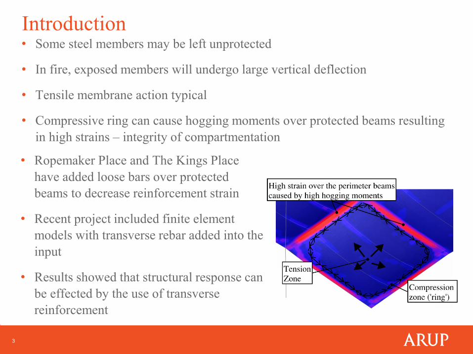
Introduction • Some steel members may be left unprotected
• In fire, exposed members will undergo large vertical deflection
• Tensile membrane action typical
• Compressive ring can cause hogging moments over protected beams resulting
in high strains – integrity of compartmentation
• Ropemaker Place and The Kings Place
have added loose bars over protected
beams to decrease reinforcement strain
• Recent project included finite element
models with transverse rebar added into the
input
• Results showed that structural response can
be effected by the use of transverse
reinforcement

4
Project background
Pros/Cons for Transverse rebar in structural fire response of a composite structure
Not included
in assessment
13 storey office building:
• Retail on ground and first floors
• Plant on levels 10 to 13
18 storey office building:
• Retail on ground and first floors
• Plant levels on levels 16 to 18
Both Buildings 6b and 7a are:
• Sprinkler protected
• 120mins fire rating separating the retail from office
• 90mins fire rating between office levels
Nova Victoria Development - London

5
Sub model analysis – Idealised geometry
Pros/Cons for Transverse rebar in structural fire response of a composite structure
Typical office floor plate

6
Sub model analysis – Material properties
Pros/Cons for Transverse rebar in structural fire response of a composite structure
• Concrete behaviour modelled in line with Eurocode 2 approach
• Concrete cracking modelled in line with the Model Code 1990 (T. Telford, 1993)
Material Model
Steel members S355
Light weight concrete Grade C28/35
Reinforcing mesh A252 mesh
Transverse rebar H16 bars at 150mm centres centred over the relevant beams
• Steel behaviour modelled in line with Eurocode 3 approach

7
Sub model analysis – Geometry and sections
Pros/Cons for Transverse rebar in structural fire response of a composite structure

8
Sub model analysis – Steel beam elements
Pros/Cons for Transverse rebar in structural fire response of a composite structure
Steel frame is constructed of nodes and beam elements.
A beam member is created:
• Element is assigned with a defined Material
• Element is assigned with a defined Part
• 2 noded beam elements with a 3rd node dictating its orientation
• Beam releases at the nodes can be specified to the required DOFs
• Each beam element is 250mm in length
• Adjacent beam elements are connected by shared nodes

9
Sub model analysis – Composite slab
Pros/Cons for Transverse rebar in structural fire response of a composite structure
Nova Victoria is a composite structure, the slab is modelled without the steel decking
0.141m
2.52E-4m
Slab structure modelled
with its effective
thickness without the
profiled decking
Steel reinforcement is
modelled as a smeared sheet of
steel within the floor slab
Floor slab
• Constructed of 5 layers (8 layers where transverse rebar is modelled)
• Each layer is assigned a thickness and a defined Material
• The elements representing the slab is meshed and assigned with this defined Part
0.141m
1.34E-3m
Transverse reinforcement
within the slab element

10
Sub model analysis – Composite slab
Pros/Cons for Transverse rebar in structural fire response of a composite structure
Composite behaviour of slab modelled by assuming full shear connection between
slab and beams.
The nodes in the shell elements (the slab elements) are made to share nodes with the
previously created beam elements
The shell elements and beam elements are OFFSET so that the centroid of each
element are not passing through each other at the reference axis but at the right
distance from the reference axis
• Each shell element is offset +0.075
• Each beam elements are offset -0.309 at both nodes
• The -0.009 offset in the beam is to account for the omitted profile decking

11
Sub model – Boundary Conditions
Pros/Cons for Transverse rebar in structural fire response of a composite structure

12
Sub model – Loading
Pros/Cons for Transverse rebar in structural fire response of a composite structure
• Self-weight of structure
• Typical office floor design load
• Column loads obtained by structural engineers
• Façade load (line load)
• Loads from adjacent floor plates (line load)

13
Sub model – Thermal loading
Pros/Cons for Transverse rebar in structural fire response of a composite structure
Applied to the relevant shells/beams
Create the temperature to be experienced by the relevant beam or in the slab
• Heat transfer analysis method
• Lumped mass – steel
• 1D finite difference model - concrete
• Design fire scenarios
Design fires:
• Standard fire
• Parametric fire
• Travelling fire – Monte
Carlo Analysis Law, A.,
Stern-Gottfried, J., &
Butterworth, N. (2013). Solving
design challenges: revisiting
time equivalence. In 13th
International Conference and
Exhibition on Fire Science and
Engineering (Interflam).

14
Sub model – Thermal loading
Pros/Cons for Transverse rebar in structural fire response of a composite structure
• The calculated temperature time curves are inputed as a thermal load
• Temperature - time curves are assigned to relevant sections
• For shell elements:
• Temperature history can be applied to multiple temperature lines throughout the
thickness of the shell
• Each temperature line is assigned with a defined load curve and the depth in the
shell where this temperature lies
• Temperature at the element integration points determined by interpolation of input
• For beam elements:
• Multiple temperature histories can be
defined for a beam section
• It was assumed that the top of the beam
cross section will be cooler
s
t
s = -1 t = -1 s = 1 t = -1
s = -1 t = 0.9 s = 1 t = 0.9
s = -1 t = 0.91
s = 1 t = 1 s = 1 t = 1

15
Sub model – Results
Pros/Cons for Transverse rebar in structural fire response of a composite structure
First checks:
• Global stability
• Slab runaway
• Column stability
• Reinforcement strain
Check against:
• Structure stability
• Integrity of floor
compartmentation

16
90 minutes standard fire – Reinforcement strain
Pros/Cons for Transverse rebar in structural fire response of a composite structure
Without transverse rebar:
• Reinforcement experienced
high strain – 60 minutes
• Stability of the structure lost
before the 90 minutes
With the addition of transverse rebar:
• Strain over the protected beams
decreased
• Higher level of strains at transverse
bar edges
• Structural stability maintained
throughout
17
Addition of transverse rebar
Pros/Cons for Transverse rebar in structural fire response of a composite structure
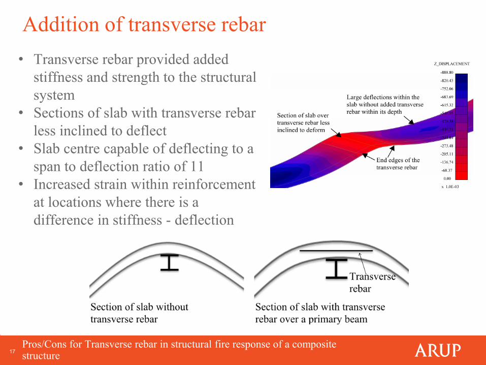
• Transverse rebar provided added
stiffness and strength to the structural
system
• Sections of slab with transverse rebar
less inclined to deflect
• Slab centre capable of deflecting to a
span to deflection ratio of 11
• Increased strain within reinforcement
at locations where there is a
difference in stiffness - deflection
18
Worst case heating regime – fast burning fire
Pros/Cons for Transverse rebar in structural fire response of a composite structure
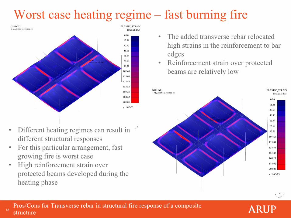
• Different heating regimes can result in
different structural responses
• For this particular arrangement, fast
growing fire is worst case
• High reinforcement strain over
protected beams developed during the
heating phase
• The added transverse rebar relocated
high strains in the reinforcement to bar
edges
• Reinforcement strain over protected
beams are relatively low

19
Storage loading – long slow burning fire
Pros/Cons for Transverse rebar in structural fire response of a composite structure
Before first beam
element failed
When first beam
element failed
• Increased rebar over the primary span
• High difference in stiffness at the edge of
the transverse rebar
• High localised straining within the slab
transferred into the underlying beams
• This caused yielding in the lower flange
and web of beam elements underneath
• Beam element written off when top flange
of the beam failed
• Released energy transferred into overlying
slab

20
Concluding remarks
Pros/Cons for Transverse rebar in structural fire response of a composite structure
• Transverse rebar can give added strength and stiffness to the composite slab,
in fire
• The difference in stiffness within the slab system at the transverse rebar edge
can lead to an increase in reinforcement strain, in fire
• High reinforcement strain over the protected beams or transverse rebar edges
can lead to reinforcement rupture – integrity of floor compartmentation
• The response of the structure will vary dependent on the heating regime
experienced
• Transverse rebar can provide benefit but may also lead to reinforcement
rupture at the rebar edges
• Transverse reinforcement designed into the structure should be included in
structural fire modelling
• Scope for physical testing into relationship between transverse rebar location
and quantity against the structure stability and floor compartmentation
• Can the addition of transverse rebar be considered as a means to increase
robustness of structure or introduce unconservative structural response at fire
limit state

21 Pros/Cons for Transverse rebar in structural fire response of a composite structure
Questions?
Thank you!
Top Related