


Languages
Pages
Legal


WMTC 2009 Propulsion Plant Selection and System Integration for Naval Vessels
EAM / Scheuing 2008-09-10 1 of 22
107.10.2008 Pfad\Dateiname
Propulsion Plant Selection and System Propulsion Plant Selection and System Integration for Naval VesselsIntegration for Naval Vessels
Georg E. ScheuingProject Manager / Naval Surface Craft
Propulsion plant requirements for naval applications have seen during the last years on one side a change to mainly commercial requirements in today’s procurement programs. Nevertheless on the other side vessel operators are setting up more stringent requirements for noise, vibrations and shock both to improve combat behaviour as well as to improve the comfort for the crew on their new vessels. In parallel also the mission profiles for naval vessels have changed due to new tasks to be performed like international peacekeeping missions, fight against terrorism/asymmetrical threads, etc. These new missions and threads also influence the selection of propulsion systems. Main driving factors for vessel and propulsion system design are tightened defence budgets, forcing the procurement agencies to scrutinize their requirements closely. They are specifying more versatile, but less sophisticated ships, looking for components-of-the-shelf (COTS) featuring reduced Life Cycle Costs (LCCs), long overhaul intervals, require low manning and allow for easy maintenance. Selection of propulsion plant components is one of the most important factors to fulfil the above customer requirements. Individual design, specifications and test instructions of the various components do not guarantee the optimum overall performance of the whole propulsion system. Solutions for the respective technical and commercial demands with respect to the whole propulsion system and the responsibility for the complete propulsion plant in one hand will result in reduced interface problems and furthermore ensure for the operator one hand contractual responsibility for the complete propulsion system from installation throughout the lifetime of the ship.
WMTC 2009 Propulsion Plant Selection and System Integration for Naval Vessels
EAM / Scheuing 2008-09-10 2 of 22
Propulsion System Integration Expectations to the system integrator as well as requirements from customers are:
• Design and integration of ship propulsion systems into a ship system
• Solutions for respective technical and commercial demands with respect to the whole system and responsibility in one hand
• Co-ordination of system interfaces for the propulsion and machinery components
• Assistance during installation and setting to work
• Service and management of fault rectification during operation of the ship from one source independent of the individual component supplier
In the presentation the above will be detailed and various propulsion options for medium sized OPV’s with comparison of performance values will be shown based on the example of the future demand of OPV’s for Indian Navy and Coast Guard and also based on MTU long lasting experiences from various system integration projects.

WMTC 2009 Propulsion Plant Selection and System Integration for Naval Vessels
EAM / Scheuing 2008-09-10 3 of 22
Required Key competences of Propulsion System Integrator For carrying out propulsion system integration certain competence is required. MTU Friedrichshafen is a supplier with this key-competences:
110.10.2008 Pfad\Dateiname
System responsibility for complete custom-made propulsion system solutions
Propulsion System Integration Key Competences I
Gasturbine Packaging3.5 – 35 MWDiesel Engines
250 – 9100 kW
Ship Automation Systems Propulsion
System Components
Integration
522.10.2008 Pfad\Dateiname
MTU System Solution
AcousticsShock
Experience
Worldwide Service
Automation
Combustion Technology
InteractiveUser-Support
Propulsion System Integration Key Competences II

WMTC 2009 Propulsion Plant Selection and System Integration for Naval Vessels
EAM / Scheuing 2008-09-10 4 of 22
Overview of the technical aspects and fields for propulsion system integration
608.10.2008 Pfad\Dateiname
Propulsion System Integration
Logistics (ILS), Training, Installation Supervision, HAT & SAT Planning and Supervision
ShipTechnology
Hydrodynamics
Engine Room Arrangement
Supply Systems
Acoustics
PropulsionTechnology
Evaluation
Lay-Out
Mech. Integration
PropellerShaftingsGearbox
Engines (DE, GT)
Power PlantTechnology
Design and Lay-Out of
Genset Systems
Layout of Main Switchboards
Ships Wiring
AutomationTechnology
Remote ControlSystems
Platform Automation
Propulsion System
Monitoring &Control
In above table the various fields for propulsion system integration is shown. In particular the following tasks must be performed: • Power demand, ship speed and endurance predictions
• Evaluation of suitable system components and recommendations for selection
• Manoeuvre simulations incl. crash stop calculations
• Mechanical and Electronical Integration
• Propulsion Train Vibration Analysis
• Acoustic analysis and optimisation of the propulsion system
• Consultancy for supply system layout
• Compete Integrated Platform Management System (IPMS)
• Integrated Logistic Services incl. Training

WMTC 2009 Propulsion Plant Selection and System Integration for Naval Vessels
EAM / Scheuing 2008-09-10 5 of 22
Examples of System Integration tasks are show below: Determination of required power and ship speed prediction:
Endurance Calculation:

WMTC 2009 Propulsion Plant Selection and System Integration for Naval Vessels
EAM / Scheuing 2008-09-10 6 of 22
Ship
20V 8000
LM 2500
LM 2500
20V 8000
RemoteControlSystem
Gearbox
HydraulicCoupling
SSSClutch
SSS-Clutch
CP-Propeller
CP-Propeller
Gearbox
SSS-Clutch
HydraulicCoupling
SSS-Clutch
StarboardSystem
PortSystem
Ship
20V 8000
LM 2500
LM 2500
Ship
20V 8000
LM 2500
LM 2500
20V 8000
RemoteControlSystem
20V 8000
RemoteControlSystem
Gearbox
HydraulicCoupling
SSSClutch
SSS-Clutch
CP-Propeller
CP-Propeller
Gearbox
SSS-Clutch
HydraulicCoupling
SSS-Clutch
StarboardSystem
PortSystem
Ship Manoeuvre Simulation:
Simulation model comprising:
• Diesel Engine
• Gas turbine
• Gearbox
• Propeller
• Ship characteristics Example Crash Stop simulation
-0,60
-0,40
-0,20
0,00
0,20
0,40
0,60
0,80
1,00
0 5 10 15 20 25 30 35 40 45 50 55 60
time [sec]
% o
f Val
uese
e le
gend
Ship Speed [40 kts]Eng. Speed [1.500 rpm]Fuel Rack Pos. [60 deg]Load Control Line [60 deg]Prop. Pitch [40 deg]No. of TurbochargersPropeller Thrust [1.500 kN]
Fuel Stopat max Engine Power/Speed

WMTC 2009 Propulsion Plant Selection and System Integration for Naval Vessels
EAM / Scheuing 2008-09-10 7 of 22
Mounting System Design: (Selection and design of resilient mounting system)
0
10
20
30
40
50
60
70
80
90
31,5 63 125 250 500 1000 2000 4000 8000 f [Hz]
Lv re
. 5*1
0-8
m/s
StandardOption 1Option 2Option 3Option 4
The diagram is showing possible structure borne noise levels depending on mounting system design. Shown is a comparison of from standard single resilient to special double resilient mounting system including sound enclosure. Supply System Design: (Example Engine Room Ventilation System with NBC Condition)

WMTC 2009 Propulsion Plant Selection and System Integration for Naval Vessels
EAM / Scheuing 2008-09-10 8 of 22
Propulsion Plant Automation: (Example pages: Ship area-, Propulsion plant- and GT- monitoring)
Extensions and Options in the responsibility of System Integrator with respect to Propulsion Plant Automation:
• Consoles Tailored to application and customer specific requirements.
• Machinery Telegraph System - MTS Emergency back-up system.
• Electrical Power Management - EPMS Electric Power Management System with data link to the Ship Automation
• Fire Detection System - FDS Fire Alarm and Detection System with data link to the Ship Automation
• Battle Damage Control System (BDCS) Tailored to application and customer specific requirements.
• On Board Training System (OBTS) Tailored to application and customer specific requirements.
• Accessories Approved and tested cables, sensors, solenoids, actuators, etc. to optimize interfacing and sourcing.
• Further extensions Navigation systems, radar, ECDIS, communication systems, voyage data recorder, CCTV systems, with data link to the Ship Automation

WMTC 2009 Propulsion Plant Selection and System Integration for Naval Vessels
EAM / Scheuing 2008-09-10 9 of 22
Example “Killcard” BDCS and Overview OBTS:
Example FIFI system and and Tank Monitoring system:

WMTC 2009 Propulsion Plant Selection and System Integration for Naval Vessels
EAM / Scheuing 2008-09-10 10 of 22
Examples / MTU references of Propulsion System Integration MTU has successfully performed PSI for various propulsion systems MTU accumulated PSI analysis know-how for both mechanical and electronical interfaces MTU delivers and takes over the responsibility for hardware and services for complete propulsion systems MTU is fully capable of dealing with GE LM2500/+/G4 engines as a certified marine gas turbine packager References of Propulsion System Integration by MTU:
• KDX I, Republic of Korea Navy
• Milgem Corvette, Turkish Navy
• Corvettes „Baynunah“, UAE Navy
• National Security Cutter, US Coastguard
• X-Craft „Sea Fighter“, US Navy
• various Patrol Vessels

WMTC 2009 Propulsion Plant Selection and System Integration for Naval Vessels
EAM / Scheuing 2008-09-10 11 of 22
New Corvette Program Milgem (Turkish Navy): Length: 99 m, Beam: 14.4 m, Draft: 3.75 m Displacement: 2000 t , Max. Speed: > 29 kn
MTU Scope of Supply MILGEM:
• 2 x MTU16V 595 TE90 DE in sound enclosures
• 1 x MTU LM2500 GT in MTU module
• RENK CODAG gearboxes
• VA Tech Escher Wyss Shafting and Propellers
• Machinery Control System MCS-5 and RCS-5
Propulsion Plant overview

WMTC 2009 Propulsion Plant Selection and System Integration for Naval Vessels
EAM / Scheuing 2008-09-10 12 of 22
Detail of Propulsion Module “MILGEM”

WMTC 2009 Propulsion Plant Selection and System Integration for Naval Vessels
EAM / Scheuing 2008-09-10 13 of 22
National Security Cutter (USCG): MTU Scope of Supply:
• 2 x 20V 1163 TB93 Diesel Engine
• 1 x GE LM2500 Gas Turbine
• Renk CoDAG gearboxes with Cross Connect
• 2 x RR Shaftlines and Propellers
• Propulsion Monitoring Control System and Remote Control System
Propulsion Plant Arrangement NSC

WMTC 2009 Propulsion Plant Selection and System Integration for Naval Vessels
EAM / Scheuing 2008-09-10 14 of 22
Propulsion plant selection Criteria for propulsion plant selection:
• Required Vessel Speed / Power Requirement
• Through Live Costs (Invest costs, Fuel costs, Maintenance costs..)
• Manning considerations
• Space / Weight Restrictions
• Vessel Operating Profile
• Redundancy / Safety considerations
• Shock / Noise Requirements
A propulsion plant selection study using the new OPV planned by the Indian Coast Guard as an example was performed considering the following vessel data:
Length: 90 m Beam: 12 m Draft: 6 m Displacement 1800 to

WMTC 2009 Propulsion Plant Selection and System Integration for Naval Vessels
EAM / Scheuing 2008-09-10 15 of 22
Calculation of power requirement based on vessel data:
Power vs. Ship Speed
0
5.000
10.000
15.000
20.000
25.000
30.000
0 5 10 15 20 25 30 35
Ship Speed [kn]
Pow
er [k
W]
Brake PowerEffective PowerTheor. Prop. Curve ~v³
3x 20V8000 (3x 9100 kW)
29,8 kn
Power vs. Ship Speed
0
5.000
10.000
15.000
20.000
25.000
30.000
0 5 10 15 20 25 30 35
Ship Speed [kn]
Pow
er [k
W]
Brake PowerEffective PowerTheor. Prop. Curve ~v³
3x 20V8000 (3x 9100 kW)
29,8 kn
Resistance curve
Required Power
05.000
10.00015.000
20.00025.00030.000
35.00040.000
45.00050.000
0 5 10 15 20 25 30 35 40
Vessel Speed [ kn ]
Bra
ke P
ower
[ kW
]
27.500 kW

WMTC 2009 Propulsion Plant Selection and System Integration for Naval Vessels
EAM / Scheuing 2008-09-10 16 of 22
Vessel Operating Profile (only example)
Design Requirements vs. Actual Profile As power requirement increases with vessel speed on cubic law, vessel speed requirement should be questioned in detail during design phase.
0
2
4
6
8
10
12
14
16
1 2 3 4 5 6 7 8 9 10 11 12 13 14 15 16 17 18 19 20 21 22 23 24 25 26 27 28 29 30 31 32 33 34 35
Perc
ent o
f Tot
al T
ime
Und
erw
ay
DDG-51 Peacetime TLR
DDG-51 Wartime TLR
DDG-51 1998 Actual

WMTC 2009 Propulsion Plant Selection and System Integration for Naval Vessels
EAM / Scheuing 2008-09-10 17 of 22
Configuration Engine-typePowerengine
[kW]
Powertotal[kW]
EstimatedVessel speed
[kn]
EstimatedBudgetary cost
(engines+gearboxes)[ % ]
Estimatedweight
(engines+gearboxes)[ tons ]
2-shaft Direct Drive 2 x 20V 8000 9100 18200 26,5 100 140
3-shaft Direct Drive 3 x 20V 8000 9100 27300 29,8 148 210
2-shaft CODADwith Cross-connect GB
3 x 20V 8000 9100 27300 29,8 166 230
2-shaft CODAD(U-Arrangement GB)
4 x 20V 8000 7200 28800 30,3 159 255
2-shaft CODAD(U-Arrangement GB)
4 x 20V 8000 8200 32800 32,0 177 262
2-shaft CODAD(U-Arrangement GB)
4 x 20V 8000 9100 36400 33,3 193 268
2 x 16V4000 2880
1 x LM 2500 20000
2 x 16V4000 2880
1 x LM 2500 20000
2 x 20V 8000 7200
1 x LM 2500 20000
3-shaft2-shaft Diesel plus1 Booster WJ
34400 32,6 223
190
1553-shaft2-shaft Diesel plus1 Booster WJ
25760 29,3
2-shaft CODAGwith Cross-connect GB 25760 29,3 130
67
143
Comparison of possible propulsion plant options (Vessel speed versus budgetary costs and propulsion plant weight - only engines and gearboxes - without shafting and propeller)
WMTC 2009 Propulsion Plant Selection and System Integration for Naval Vessels
EAM / Scheuing 2008-09-10 18 of 22
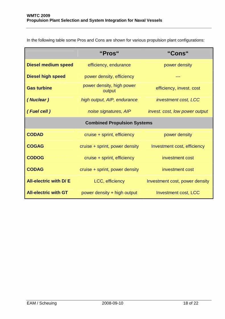
In the following table some Pros and Cons are shown for various propulsion plant configurations:
“Pros“ “Cons“
Diesel medium speed efficiency, endurance power density
Diesel high speed power density, efficiency ---
Gas turbine power density, high power output efficiency, invest. cost
( Nuclear ) high output, AIP, endurance investment cost, LCC
( Fuel cell ) noise signatures, AIP invest. cost, low power output
Combined Propulsion Systems
CODAD cruise + sprint, efficiency power density
COGAG cruise + sprint, power density Investment cost, efficiency
CODOG cruise + sprint, efficiency investment cost
CODAG cruise + sprint, power density investment cost
All-electric with D/ E LCC, efficiency Investment cost, power density
All-electric with GT power density + high output Investment cost, LCC

WMTC 2009 Propulsion Plant Selection and System Integration for Naval Vessels
EAM / Scheuing 2008-09-10 19 of 22
CODAG propulsion plant on CPP:
CODELAG propulsion plant on CPP:

WMTC 2009 Propulsion Plant Selection and System Integration for Naval Vessels
EAM / Scheuing 2008-09-10 20 of 22
Redundancy and survivability considerations: Combined propulsion plants offer some advantages with respect to redundancy and survivability which also must be considered when finally selecting the propulsion plant configuration. As an example this is shown for the 3-engine / 2-shaft CODAD propulsion plant:.
Type of Damage Remaining Operating Modes
One diesel inoperable Other diesel engines (one or two) operating on both propellers
Two diesels inoperable Third DE driving one or two propeller shafts
Cross connect gear inoperable Each front diesel drives its own propeller shaft
One main gear and cross connect gear inoperable
Diesel on other main gear drives referring shaft
Aft DE compartment flooded Front DE can operate without restrictions
Front DE compartment flooded Aft DE driving one or two propeller shafts
WMTC 2009 Propulsion Plant Selection and System Integration for Naval Vessels
EAM / Scheuing 2008-09-10 21 of 22
Summary of Customer requirements and key selection criteria for propulsion plant: These are:
• Invest cost (Value for money)
• Life Cycle Costs, dominated by fuel consumption
• Reliability / Availability / Maintainability
• Low-load operation capability
• Capability to run in single engine operation efficiently
• Good manouevring characteristics
• Compact design, saving space for mission payload and/or crew
• Logistic support (parts, documentation, training, service)
• Logistic commonality with other vessels in the fleet
• Redundancy
• References

WMTC 2009 Propulsion Plant Selection and System Integration for Naval Vessels
EAM / Scheuing 2008-09-10 22 of 22
Conclusion
• The propulsion system is elemental for the vessel‘s operational economy and flexibility.
• Careful system analysis, careful selection of the propulsion plant components and respective integration into the system „ship“ is a vital requirement for the customer.
• Propulsion system integration requires competent and experienced propulsion system integrator with know-how for both mechanical and electronical/automation components integration.
Customer Advantages and why Propulsion System Integration by MTU
• One hand contractual responsibility for the complete propulsion system, both for the mechanical systems and components as well as for electrical/automation system and components
• Proven system integration know-how and experience
• Full assistance from design phase to commissioning of the vessel and throughout the further vessel lifetime
• Single source logistics for the Navy
• Holistic problem solving during commissioning, trials and the in-service period
• Reduction of technical and commercial risk, necessary manpower and administration complexity on the shipyards side
MTU takes over the system integrator role when also being selected as propulsion system supplier
MTU can be Your Partner for:
Propulsion System Integration
Contact: [email protected]
Top Related