


Languages
Pages
Legal


Pressure Maintenance
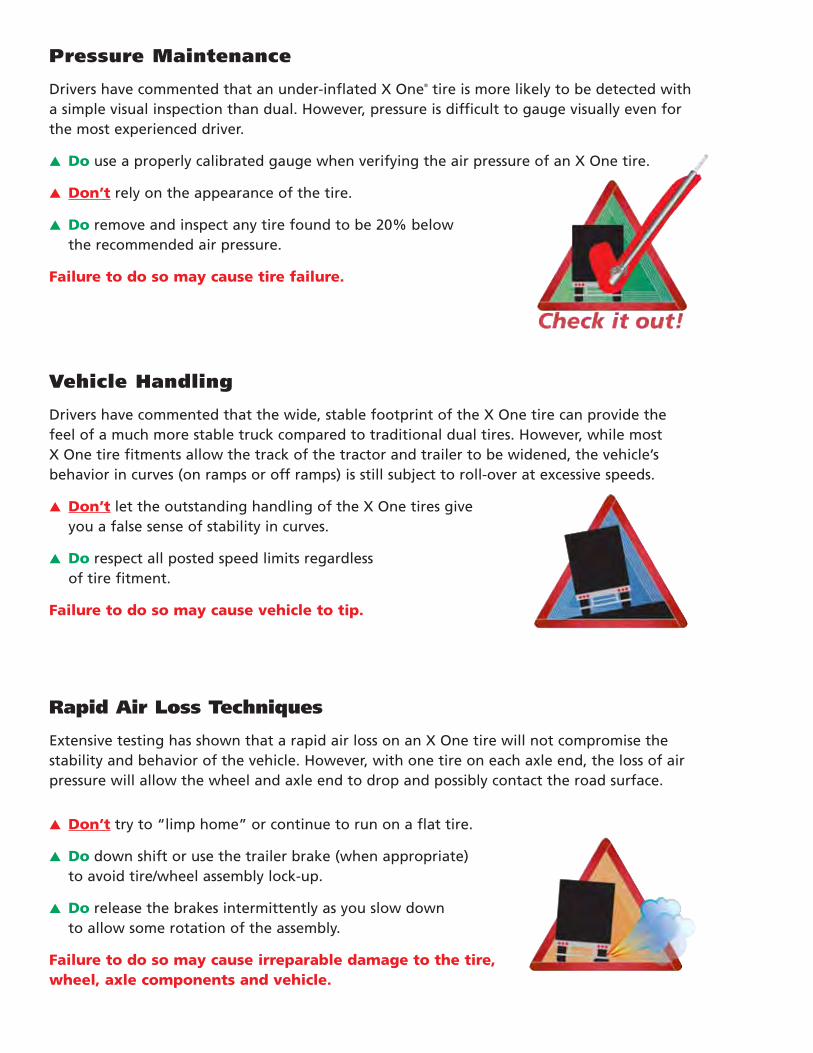
Drivers have commented that an under-inflated X One® tire is more likely to be detected with a simple visual inspection than dual. However, pressure is difficult to gauge visually even for the most experienced driver.
▲ Do use a properly calibrated gauge when verifying the air pressure of an X One tire.
▲ Don’t rely on the appearance of the tire.
▲ Do remove and inspect any tire found to be 20% below the recommended air pressure.
Failure to do so may cause tire failure.
Vehicle Handling
Drivers have commented that the wide, stable footprint of the X One tire can provide the feel of a much more stable truck compared to traditional dual tires. However, while most X One tire fitments allow the track of the tractor and trailer to be widened, the vehicle’s behavior in curves (on ramps or off ramps) is still subject to roll-over at excessive speeds.
▲ Don’t let the outstanding handling of the X One tires give you a false sense of stability in curves.
▲ Do respect all posted speed limits regardless of tire fitment.
Failure to do so may cause vehicle to tip.
Rapid Air Loss Techniques
Extensive testing has shown that a rapid air loss on an X One tire will not compromise thestability and behavior of the vehicle. However, with one tire on each axle end, the loss of airpressure will allow the wheel and axle end to drop and possibly contact the road surface.
▲ Don’t try to “limp home” or continue to run on a flat tire.
▲ Do down shift or use the trailer brake (when appropriate) to avoid tire/wheel assembly lock-up.
▲ Do release the brakes intermittently as you slow down to allow some rotation of the assembly.
Failure to do so may cause irreparable damage to the tire, wheel, axle components and vehicle.

IntroductionRead this manual carefully — it is important for the SAFE operation and servicing of your tires.
The purpose of this manual is to provide you, the Michelin® Truck Tire customer, with some usefulinformation to help you obtain maximized performance and minimized cost per mile. Your Michelin® radial tiresare a significant investment and should be protected like any other investment. This manual will show you howto do this by increasing your knowledge of tires regarding their selection, vehicle characteristics that affectperformance, maintenance, and extending tire life through repair and retreading. For complete tirespecifications, refer to application data books, contact your local Michelin Representative, or refer to theMichelin website: www.michelintruck.com.
ADDITIONAL REFERENCES
For additional information consult the following manuals/publications:Michelin Truck Tire Data Book . . . . . . . . . . . . . . . . . . . . . . . . . . . . . . . . . . . . . . . . . . . . . . . . . . . . . . . . . . . . . . . . . . . . . . MWL40731Michelin Commercial Truck Tire Nail Hole Radial Tire Repair Manual . . . . . . . . . . . . . . . . . . . . . . . . . . . . . . . . . . MWT40163Crown/Sidewall Repair Template . . . . . . . . . . . . . . . . . . . . . . . . . . . . . . . . . . . . . . . . . . . . . . . . . . . . . . . . . . . . . . . . . . . MWT40192Truck Tire Limited Warranty and Driver’s Manual . . . . . . . . . . . . . . . . . . . . . . . . . . . . . . . . . . . . . . . . . . . . . . . . . . . . MWE40021X One® Tire Brochure . . . . . . . . . . . . . . . . . . . . . . . . . . . . . . . . . . . . . . . . . . . . . . . . . . . . . . . . . . . . . . . . . . . . . . . . . . . . . . MWL41924X One Driver Information . . . . . . . . . . . . . . . . . . . . . . . . . . . . . . . . . . . . . . . . . . . . . . . . . . . . . . . . . . . . . . . . . . . . . . . . . . MWL42987
Technical Bulletins: www.michelintruck.com
CDs/DVDs:X One Tire Presentation . . . . . . . . . . . . . . . . . . . . . . . . . . . . . . . . . . . . . . . . . . . . . . . . . . . . . . . . . . . . . . . . . . . . . . . . . . . . MWV42737X One Tire Driver Information DVD . . . . . . . . . . . . . . . . . . . . . . . . . . . . . . . . . . . . . . . . . . . . . . . . . . . . . . . . . . . . . . . . . MWV42991

Michelin® tires and tubes are subject to a continuousdevelopment program. Michelin North America, Inc.
reserves the right to change product specifications at any time without notice or obligation.
Please consult rim manufacturer’s load and inflation limits. Never exceed rim manufacturer’s limits without
permission of component manufacturer.
Tire and Wheel Nomenclature .......................... 1-8
SELECTING A TIRE ........................................................................ 2-3
Equivalent X One® Tire Sizes
RPM’s and Retrofits to X One® Tires
Tire Marking / Load Range / I.S.O. / D.O.T. Descriptions
D.O.T. Sidewall Markings
Tire Applications and Design
SELECTING A WHEEL ................................................................... 4-5
Outset / Inset
Drop Centers
Valve Systems
WHEEL SYSTEMS ......................................................................... 6-8
Steel vs Aluminum
Stud Piloted Wheels
Special Fasteners
Hub Piloted Wheels
Torque
Proper Fastener for X One® Tire Steel Stud Piloted Wheels
WHEEL SPECIFICATIONS ............................................................ 9-10
14.00 x 22.5" – 15-Degree Drop Center Wheel Specifications
Special Provision for Steer Axle Use on 13.00 x 22.5" Wheels
13.00 x 22.5" – 15-Degree Wheel Specifications
Truck Technical Specifications........................ 11-24
AXLES AND WHEEL ENDS ....................................................... 12-15
Axle Identification Tags
Load Ratings
Axle Track Widths
Use of 2” Outset Wheel with X One® Tires
SPINDLES ....................................................................................... 16
OVERALL VEHICLE TRACK AND WIDTH ...................................... 17
BEARINGS ...................................................................................... 18
ENGINE COMPUTERS .................................................................... 18
AIR INFLATION AND PRESSURE MONITORING SYSTEMS ..... 19-20
The Use of Pressure Monitoring and Inflation
Systems with Michelin Truck Tires
Central Tire Inflation Systems on Trailers
and Missed Nail Holes
TRUCK TYPE BY WEIGHT CLASS ............................................. 21-22
X One Tires in 4 x 2 Application
X One Tire Maintenance..................................... 25-55
X ONE TIRE — MOUNTING ..................................................... 24-26
Mounting Setup
Wheel Preparation
Inspecting for Damages
Lubricating the Tire and Wheel
Mounting the X One Tire
X ONE TIRE — DEMOUNTING ................................................. 27-29
2-Bar Demount Method
3-Bar Demount Method
Demounting the Second Bead
MISMOUNT .............................................................................. 30-31
3 Easy Steps to Help Minimize Mismounted Tires
TIME STUDY — X ONE® TIRE VS DUAL ................................... 32-33
Demounting the X One® Tires
Demounting the Dual
Mounting the X One® Tires
Mounting the Dual
AIR INFILTRATION .................................................................... 34-35
AIR PRESSURE .......................................................................... 36-38
X One® Air Pressure Maintenance Practices
HOW TO PROPERLY MEASURE PRESSURE ............................. 39-44
Temperature/Pressure Relationship Chart
The Use of Nitrogen in Michelin Truck Tires
Runflat and Zipper Ruptures
Tire Inspection
X One® Tires Load and Inflation Tables
IRREGULAR TIRE WEAR ........................................................... 45-46
Tractor: Heel-Toe/Block-Edge Wear, Center Wear,
River Wear Only
Trailer: Step-Shoulder/Localized Wear, Shoulder Cupping,
Brake Skid
ALIGNMENT AND VIBRATION ................................................. 47-49
Introduction
Axle Skew
Trailer Alignment
Vibration
Balance
TREAD DEPTH PULL POINTS......................................................... 50
CARE, CLEANING AND STORAGE................................................. 51
Diesel Fuel Contamination
Cleaning and Protection
SEALANTS...................................................................................... 52
VALVE STEM INSPECTION ............................................................. 52
Table of Content

Retread and Repair Recommendations... 53-58
X ONE® RETREAD AND REPAIR RECOMMENDATIONS ................ 54
Retread Limits
Casing Age Limits
Initial Inspection
Shearography
Buffing
GENERAL REPAIR GUIDELINES ................................................ 55-56
Skiving
REPAIR LIMIT SPECIFICATIONS ................................................ 57-58
Nail Hole Repairs
Section Repairs
Spot Repairs
X One® XZU®S Repair Recommendations
Bead Repairs
Inner Liner Repairs
Builder
Enveloping
Curing
Final Inspection
Operation and Handling .................................... 59-70
OPERATION AND HANDLING .................................................. 60-65
Over-steer
Under-steer
Hydroplaning
Rollover Threshold
Jack-Knife
Traction
Chains
Stopping Distances
Limping Home
State and Local Regulations
HEAT STUDY ............................................................................ 66-69
Brake Heat Overview
Brake Heat Evaluation: X One® Tires vs Duals
Appendix ......................................................................... 71-76
ISO LOAD INDEX AND SPEED SYMBOL....................................... 72
DEFINITIONS............................................................................. 73-74
SPECIAL TOOLS/MOUNTING TOOLS ...................................... 75-76
Index.................................................................................... 77-78

Tire and WheelNomenclature
SELECTING A TIRE . . . . . . . . . . . . . . . . . . . . . . . . . 2-3Equivalent X One® Tire Sizes
RPMs and Retrofits to X One® Tires
Tire Marking / Load Range / I.S.O. / D.O.T. Descriptions
D.O.T. Sidewall Markings
Tire Applications and Design
SELECTING A WHEEL . . . . . . . . . . . . . . . . . . . . . . 4-5Outset / Inset
Drop Centers
Valve Systems
WHEEL SYSTEMS . . . . . . . . . . . . . . . . . . . . . . . . . 6-8Steel vs Aluminum
Stud Piloted Wheels
Special Fasteners
Hub Piloted Wheels
Torque
Proper Fastener for X One Tire Steel Stud Piloted Wheels
WHEEL SPECIFICATIONS . . . . . . . . . . . . . . . . . . . 9-1014.00 x 22.5" – 15-Degree Drop Center Wheel Specifications
Special Provision for Steer Axle Use on 13.00 x 22.5" Wheels
13.00 x 22.5" – 15-Degree Wheel Specifications

2
Size Design LI / Ply Rating ISO Load ISO Speed
445/50R22.5 X One® XDA-HT™ Plus L/20 161 (11,000 lbs) L (75 mph)
X One® XDA® L/20 161 (11,000 lbs) L (75 mph)
X One® XTE® L/20 161 (11,000 lbs) L (75 mph)
X One® XTA® L/20 161 (11,000 lbs) L (75 mph)
455/55R22.5 X One XDA-HT Plus L/20 164 (11,000 lbs) L (75 mph)
X One XDA L/20 164 (11,000 lbs) L (75 mph)
X One XTE L/20 164 (11,000 lbs) L (81 mph)
X One XTA L/20 164 (11,000 lbs) L (75 mph)
X One® XZU® S M/22 166 (11,000 lbs) M (75 mph)
455/45R22.5 X One® XDU® M/22 166 (11,700 lbs) J (75 mph)
SELECTING A TIRE
DOT SIDEWALL MARKINGSAll new tires sold in the United States must have a DOT
(Department of Transportation) number cured into the lower
sidewall. All retreaded tires must also have an additional DOT
branded into the sidewall. It is recommended that the retread DOT
be placed in the lower sidewall near the original DOT code. Certain
states may require labeling in addition to the Federal requirements
certifying compliance with the Industry Standard for Retreading.
Tires manufactured prior to the year 2000 end with 3 digits rather
than 4, the first two numbers indicating the week and the last one
indicating the year of production, followed by a solid triangle to
indicate the decade of 1990s. Tires made or retreaded after the year
1999 will end with a four-digit code: the first two indicate the week,
and the last two indicate the year of manufacture.
Example: DOT B6 DO AXL X 2006
New tire markings required by the Department of Transportation:
TIRE MARKINGS / LOAD RANGES / I.S.O. / D.O.T. DESCRIPTIONS
RPMs AND RETROFITS TO X ONE® TIRESGear Ratio: A change in tire dimension will result in a
change in engine RPM at a set cruise speed that will
result in a change in speed and fuel economy. The
effect of tire size change on gear ratio should be
considered in individual operations.
A decrease in tire radius will increase tractive torque
and increase indicated top speed.
An increase in tire radius will reduce tractive torque
and decrease indicated speed.
RPM/Speed/Size: These factors can affect RPM if
corresponding changes are not made to engine ratios.
Example: Going from larger diameter tire to smaller
diameter tire
If you currently run a 275/80R22.5 XDA-HT™ (509 rpm)
and change to a 445/50R22.5 X One® XDA-HT™ Plus
(514 rpm), the speedometer will indicate a slightly
higher speed than the actual speed the vehicle is
traveling.
MPH Change = Current RPM – New RPM/Current RPM
(509 - 514/509) = -.009823
-.009823 x 60 mph (Indicated Speed) = -.6 mph
Therefore, if indicated speed = 60 mph, actual speed =
59.4 mph
EQUIVALENT X ONE® SIZESWhen retrofitting X One® tires of
equivalent size, changing engine
computer RPMs (Revolutions Per
Mile) should be all that is required.
Consult your equipment manu-
facturer and Michelin representative
for details if you are retrofitting other
than equivalent sizes.
DOT
PlantTire Size Optional Code Michelin
Manufacture Date
�
� Indicates a cut and chip resistance tread compound for more aggressive environments.
X One Tire Size X One Tire RPMs Dual Size Dual RPMs
445/50R22.5 514 (X One XDA-HT Plus) 275/80R22.5 509 (XDA-HT)
455/55R22.5 493 (X One XDA-HT Plus) 11R22.5 or 275/80R24.5 495 (XDA-HT)

Long Haul (A): The Long Haul application is composed of businesses operating primarily in common carrier vocations.
Vehicle annual mileage – 80,000 to 200,000.
Regional (E): The Regional application is made up of businesses such as public utilities, government – federal, state, and
local, food distribution/process, manufacturing/process, petroleum, and schools operating within a 300-mile radius.
Vehicle annual mileage – 30,000 miles to 80,000.
On/Off Road (Y): On/Off Road tires are designed to
provide the durability and performance necessary in
highly aggressive operating conditions at limited speeds.
Vocations such as construction, mining and logging use
these highly specialized tires.
Vehicle annual mileage – 10,000 miles to 70,000.
Urban (U): Urban applications are very short
mileage with a high percentage of stop and go.
Primarily users are in retail/wholesale delivery,
bus fleets and sanitation.
Vehicle annual mileage – 20,000 miles to 60,000.
TIRE APPLICATIONS AND DESIGN
3
X One® XTA®
Fuel savings, Weight Savings,
Even Wear, 13/32nd
X One® XDA®
Fuel Efficient, Long Tread Life, 24/32nd
X One® XTE®
High Scrub, Weight Savings, Long Tread Life, 16/32nd
X One® XDA-HT™ PlusLong Original Life,
Weight SavingsAll-Weather Traction, 28/32nd
X One® XZU®SHigh Scrub Resistance,
Weight Savings, 23/32nd
4
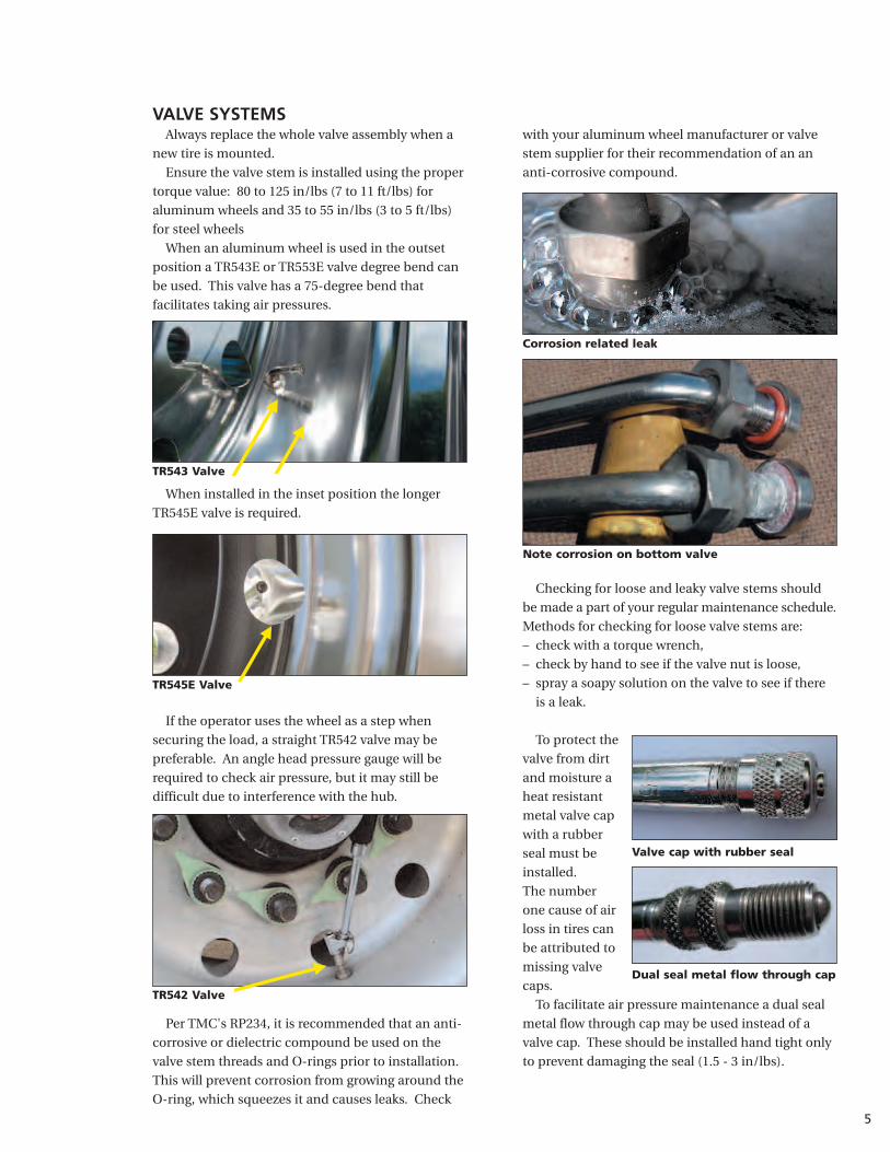
SELECTING A WHEELOUTSET/INSET
Outset: The lateral distance from the wheel centerline
to the mounting surface of the disc. Outset places the
wheel centerline outboard of the mounting (hub face)
surface. Inset places the wheel centerline inboard of the
mounting (hub face) surface, or over the axle.
USE OF 2" OUTSET WHEELSWITH X ONE® TIRES
The X One® tires (445/50R22.5 and 455/55R22.5) require
the use of 14.00 x 22.5" wheels. The majority of the wheels
currently offered have a 2" outset.
Some axle and hub manufacturers have recently clarified
and confirmed their position concerning the use of such
wheels with their respective components. While the
position of the component manufacturers is not totally
consistent, the majority view concerning the retrofit of
duals with X One® tires can be summarized as follows:
Alcoa
Outboard Inboard
Outboard Inboard
OUTSET
Disc Face
Disc Face
INSET
Accuride
Narrow Ledge
Truck and trailer manufacturers may have different
specifications. For optimum track width, stability and
payload, end-users should talk to their trailer suppliers
about the use of 83.5" axles with zero outset wheels.
End-users that have retrofitted vehicles with 2" outset
wheels should contact their respective vehicle, axle or
component manufacturers for specific application
approvals or maintenance recommendations.
NOTE: Use of outset wheels may change Gross Axle
Weight Rating (GAWR). Consult vehicle and component
manufacturer.
DROP CENTERSThe Drop Center is the well or center portion of the
wheel. This is what allows the tire to be easily mounted
on a single piece wheel: the tire bead will “drop” into
this cavity.
The 14.00 x 22.50" (15-degree bead seat) drop center
tubeless wheel required for the X One® tire has differently
styled drop centers depending on the manufacturer.
Accuride aluminum and steel wheels as well as
Hayes-Lamerz steel wheels are produced with a narrow
ledge on one side and a long tapered ledge on the other.
The narrow ledge is necessary to ease the mounting and
dismounting process.
The Alcoa aluminum wheel is manufactured with
a narrow ledge on either side. This allows it to be
mounted and dismounted from either side.
Axle Type* Spindle Type Wheel Recommendation
Drive axles “R” 2" outset wheels
Trailer axles “P” 2" outset wheels
Trailer axles “N” Check with component manufacturer
* Many other axle and spindle combinations exist. Contact axle manufacturer.
Always ensure the narrow ledge isup when mounting or demounting.
VALVE SYSTEMSAlways replace the whole valve assembly when a
new tire is mounted.
Ensure the valve stem is installed using the proper
torque value: 80 to 125 in/lbs (7 to 11 ft/lbs) for
aluminum wheels and 35 to 55 in/lbs (3 to 5 ft/lbs)
for steel wheels
When an aluminum wheel is used in the outset
position a TR543E or TR553E valve degree bend can
be used. This valve has a 75-degree bend that
facilitates taking air pressures.
When installed in the inset position the longer
TR545E valve is required.
If the operator uses the wheel as a step when
securing the load, a straight TR542 valve may be
preferable. An angle head pressure gauge will be
required to check air pressure, but it may still be
difficult due to interference with the hub.
Per TMC's RP234, it is recommended that an anti-
corrosive or dielectric compound be used on the
valve stem threads and O-rings prior to installation.
This will prevent corrosion from growing around the
O-ring, which squeezes it and causes leaks. Check
with your aluminum wheel manufacturer or valve
stem supplier for their recommendation of an an
anti-corrosive compound.
Checking for loose and leaky valve stems should
be made a part of your regular maintenance schedule.
Methods for checking for loose valve stems are:
– check with a torque wrench,
– check by hand to see if the valve nut is loose,
– spray a soapy solution on the valve to see if there
is a leak.
To protect the
valve from dirt
and moisture a
heat resistant
metal valve cap
with a rubber
seal must be
installed.
The number
one cause of air
loss in tires can
be attributed to
missing valve
caps.
To facilitate air pressure maintenance a dual seal
metal flow through cap may be used instead of a
valve cap. These should be installed hand tight only
to prevent damaging the seal (1.5 - 3 in/lbs).
TR543 Valve
TR545E Valve
TR542 Valve
Corrosion related leak
Note corrosion on bottom valve
Valve cap with rubber seal
Dual seal metal flow through cap
5
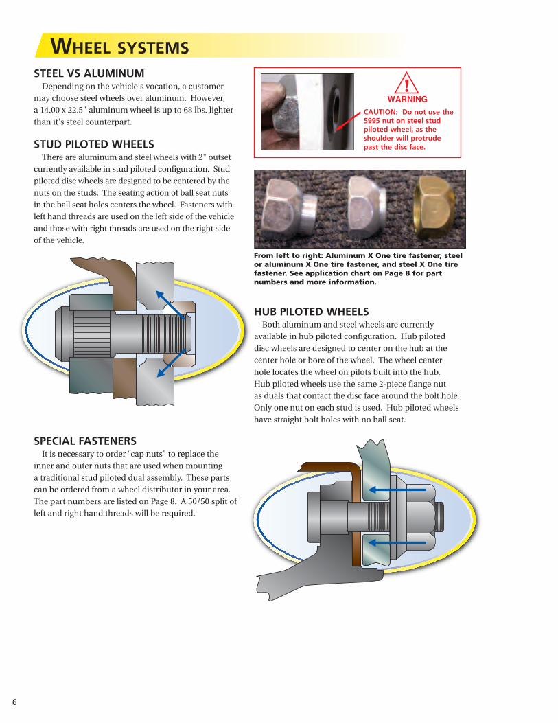
STEEL VS ALUMINUMDepending on the vehicle's vocation, a customer
may choose steel wheels over aluminum. However,
a 14.00 x 22.5" aluminum wheel is up to 68 lbs. lighter
than it's steel counterpart.
STUD PILOTED WHEELSThere are aluminum and steel wheels with 2" outset
currently available in stud piloted configuration. Stud
piloted disc wheels are designed to be centered by the
nuts on the studs. The seating action of ball seat nuts
in the ball seat holes centers the wheel. Fasteners with
left hand threads are used on the left side of the vehicle
and those with right threads are used on the right side
of the vehicle.
SPECIAL FASTENERSIt is necessary to order “cap nuts” to replace the
inner and outer nuts that are used when mounting
a traditional stud piloted dual assembly. These parts
can be ordered from a wheel distributor in your area.
The part numbers are listed on Page 8. A 50/50 split of
left and right hand threads will be required.
6
WHEEL SYSTEMS
CAUTION: Do not use the5995 nut on steel studpiloted wheel, as theshoulder will protrude past the disc face.
From left to right: Aluminum X One tire fastener, steelor aluminum X One tire fastener, and steel X One tirefastener. See application chart on Page 8 for part numbers and more information.
HUB PILOTED WHEELSBoth aluminum and steel wheels are currently
available in hub piloted configuration. Hub piloted
disc wheels are designed to center on the hub at the
center hole or bore of the wheel. The wheel center
hole locates the wheel on pilots built into the hub.
Hub piloted wheels use the same 2-piece flange nut
as duals that contact the disc face around the bolt hole.
Only one nut on each stud is used. Hub piloted wheels
have straight bolt holes with no ball seat.

Hub piloted mounting system:Most North American manufacturers of highway
trucks, tractors and trailers, which incorporate the
hub piloted wheel mounting system, require wheel
studs and two-piece flange nuts with metric threads.
Most frequently these are M22 x 1.5. Before
installing two-piece flange nuts apply two drops of
SAE 30W oil to the last two or three threads at the
end of each stud AND two drops to a point between
the nuts and flanges. This will help ensure that the
proper clamping force is achieved when final torque
is reached. Lubrication is not necessary with new
hardware.
Torque Sequence:Both stud piloted and hub piloted wheel systems
use the same torque sequence. Tighten the flange
nuts to 50 foot-pounds using the sequence shown.
Check the disc wheel for positioning on the pilots
and proper seating against the drum face. Tighten
to 450 to 500 foot-pounds using sequence shown.
After 50 to 100 miles of operation, torque should
be rechecked.
It is important to note that some hub piloted and
stud piloted wheels may have the same bolt circle
pattern. Therefore, they could mistakenly be
interchanged. Each mounting system requires the
correct mating parts. It is important that the proper
components are used for each type of mounting and
that the wheel is fitted to the proper hub.
If hub piloted wheel components (hubs, wheels,
and fasteners) are mixed with stud piloted wheel
components, loss of torque, broken studs, cracked
wheels and possible wheel loss can occur, which can
lead to injury or death. These parts are not designed
to be interchangeable. Refer to TMC RP 217A,
Attaching Hardware for Disc Wheels, and TMC RP
608a, Brake Drums and Rotors.
NOTE: Some states and provinces have laws that
dictate sufficient thread engagement or thread
engagement past the nut body. Make sure you know
the laws for the states and provinces in which you
operate and comply.
TORQUEStud piloted, ball seat mounting system:
Left hand threads are used on the left side of the
vehicle. Right hand threads are used on the right
side of the vehicle. Tighten the nuts to 50 foot-
pounds using the sequence shown. Check that the
wheel is properly positioned then tighten to
recommended torque using the sequence shown.
It is recommended that studs and nuts on a stud
piloted mounting system should be free of rust and
debris. They should then be torqued “dry” to
450-500 ft lbs. After 50 to 100 miles of operation,
torque should be rechecked.
7
Lubricate Here
Correct components must be used.
Eight Stud
Ten Stud

8
Part No. Replaces Thread Hex High Application and General Information
5554R&LAlcoa 5554R&L
Budd 706 13/43⁄4" - 16 11⁄2" 1"
For Single Mounting
of Alcoa Forged
Aluminum Disc Wheels
and Steel Stud Piloted Wide
Single Wheels.
5995R&L
Alcoa 5995R&L
Webb 178950R
178951L
3⁄4" - 16 11⁄2" 13⁄8"
For Alcoa Wide Base Aluminum
Wheels – “Long Grip” Cap Nut
Larger height provides greater lug
wrench contact into wheel.
5652R&L Zinc
Dichromate
Plating
Accuride NTL/NTR 25
Budd 37888/9
Gunite 2564/65
Motor Wheel 84523/24
3⁄4" - 16 11⁄2" 7⁄8"Steel Wheel:
Single Stud Mounting
Front and Rear
5977R&L
Hardened Zinc
Yellow
Dichromate
Plating
Alcoa 5977 R&L
Accuride NTL/NTR 25
Alcoa 5552R&L
Budd 37891/2
11⁄8" - 16 11⁄2" 7⁄8"Single Large Stud Mounting
Front and Rear
It is important that the proper fasteners be used when
mounting the X One® tire on stud piloted wheels. If a
fastener specified for the stud piloted aluminum wheel
is used on a steel wheel, it will bottom out on the brake
drum and the proper clamping force necessary to help
ensure that the torque on the wheel remains constant
will not be achieved, possibly resulting in a “wheel off”
situation.
In the table below, the top fastener, Part No. 5554R&L
is primarily for the Alcoa single mounted stud piloted
aluminum wheel (ex. 8.25 x 22.5") and 14.00 x 22.5" wide
base stud piloted steel wheel. Part Number 5995R&L is
for the Alcoa 14.00 x 22.5" wide base stud piloted
aluminum wheels.
The last two fasteners Part No.5652R&L for a 3⁄4"-16
studs and 5977R&L for a 11⁄8"-16 studs are specified for
the 14.00 x 22.5" stud piloted steel wheel.
PROPER FASTENER FOR X ONE® TIRE ONSTUD PILOTED WHEELS

9
WHEEL SPECIFICATIONS14.00 x 22.5" – 15-DEGREE DROP CENTER WHEEL SPECIFICATIONS
Manufacturer Material Part Number Finish Weight (lb) Outset Inset Max Load & Inflation
10-hole, stud located, ball seat mounting – 11.25 in. bolt hole circle
Alcoa Aluminum 841100 Machined 71 2.0 0.87 12,800 @ 125
Alcoa Aluminum 841102 Polished 71 2.0 0.87 12,800 @ 125
Hayes Lemmerz Steel 10070TW White 125 2.00 1.49 11,000 @ 125
Hayes Lemmerz Steel 10070TC Chrome 125 2.00 1.49 11,000 @ 125
10-hole, hub piloted mounting – 285.75 mm bolt hole circle
Alcoa Aluminum 841600 Machined 71 2.0 0.87 12,800 @ 125
Alcoa Aluminum 841602 Polished 71 2.0 0.87 12,800 @ 125
Alcoa Aluminum 841610 Machined 71 1.13 0 12,800 @ 125
Alcoa Aluminum 841612 Polished 71 1.13 0 12,800 @ 125
Accuride Aluminum 29660ANP Machined 70 2.0 0.88 12,800 @ 130
Accuride Aluminum 29660AOP Polished 70 2.0 0.88 12,800 @ 130
Accuride Aluminum 40016ANP Machined 71 0.56 0.56 12,800 @ 130
Accuride Aluminum 40016AOP Polished 71 0.56 0.56 12,800 @ 130
Accuride Steel 29890 White 132 2.0 1.38 12,800 @ 125
Accuride Steel 29891 White 132 0 0.63 12,800 @ 125
Hayes Lemmerz Steel 10027TW White 136 2.00 1.49 11,000 @125
Hayes Lemmerz Steel 10031TW White 136 0.51 1.49 12,300 @ 120
Hayes Lemmerz Steel 10027TC Chrome Clad 136 2.00 1.49 11,000 @ 125
Hayes Lemmerz Steel 10031TC Chrome Clad 136 0.51 1.49 12,300 @ 120
Note: The table provided is for reference only. Wheel specific questions should be directed to the wheel manufacturer.Alcoa at www.alcoawheels.com or 1-800-242-9898;Accuride at www.accuridecorp.com or 1-800-626-7096;Hayes Lemmerz at www.hayes-lemmerz.com or 1-800-521-0515.

10
13.00 x 22.5" – 15-DEGREE WHEEL SPECIFICATIONS
SPECIAL PROVISION FOR STEER AXLE USE ON 13.00 x 22.5" WHEELS455/55R22.5 load range ‘M’ may be fitted with 13.00 x 22.5" wheels for first life use on the steer axles. The reduced loads shown
in the following table must be observed.
MANUFACTURER MATERIAL PART NUMBER FINISH WEIGHT (LB) OUTSET INSET MAX LOAD & INFLATION
10-hole, stud located, ball seat mounting – 11.25" bolt hole circle
Accuride Steel 29802 White 129 4.95 4.32 11,000 @ 110
Hayes Lemmerz Steel 10060TW White 121 4.83 4.32 11,000 @ 130
10-hole, hub piloted mounting – 285.75 mm bolt hole circle
Accuride Steel 29811 White 129 4.95 4.32 11,000 @ 110
Hayes Lemmerz Steel 10059TW White 121 4.83 4.32 11,000 @ 130
Technical specifications for Michelin 455/55R22.5 LRM with 13.00 x 22.5" wheels steer axle, first life only.
To determine the proper load/inflation table, always refer to the markings on the tire sidewall for maximum load at cold pressure.Contact your Michelin dealer for tires with maximum loads and pressures other than indicated here.
Load and inflation industry standards are in a constant state of change. Michelin continually updates its product information to reflect these changes.Therefore, printed material may not reflect the current load and inflation information.
NOTE: Never exceed the wheel manufacturer’s maximum air pressure limitation.In order to be under Federal maximum width of 102", an inset wheel must be used. A 4.32" inset will net 101.5" overall width on some refuse vehicles.There are currently steel wheels available from Accuride and Hayes Lemmerz. Caution: Ensure the wheel does not interfere with vehicle components whenmaking full turns.
Dimension Load psi 75 80 85 90 95 100 105 110 115 120
Range kPa 520 550 590 620 660 690 720 760 790 830
455/55R22.5 LRM lbs. per axle 13740 14460 15180 15880 16600 17280 17980 18660 19340 20000
kg. per axle 6240 6520 6900 7180 7560 7820 8100 8460 8720 9070
Dimension Load Loaded Radius RPM Max. Load Single
Range in. mm. lbs. psi kg. kPa
455/55R22.5 LRM 19.5 496 493 10000 120 4535 830
Note: The table provided is for reference only. Wheel specific questions should be directed to the wheel manufacturer.Accuride at www.accuridecorp.com or 1-800-626-7096;Hayes Lemmerz at www.hayes-lemmerz.com or 1-800-521-0515.

Truck TechnicalSpecifications
AXLES AND WHEEL ENDS . . . . . . . . . . . . . . . . 12-15Axle Identification Tags
Load Ratings
Axle Track Widths
Use of 2” Outset Wheel with X One Tires
SPINDLES . . . . . . . . . . . . . . . . . . . . . . . . . . . . . . . . 16
OVERALL VEHICLE TRACK AND WIDTH . . . . . . . . 17
BEARINGS . . . . . . . . . . . . . . . . . . . . . . . . . . . . . . . . 18
ENGINE COMPUTERS . . . . . . . . . . . . . . . . . . . . . . . 18
AIR INFLATION AND PRESSURE MONITORING SYSTEMS . . . . . . 19-20
The Use of Pressure Monitoring and Inflation Systems with Michelin Truck Tires
Central Tire Inflation Systems on Trailers and Missed Nail Holes
TRUCK TYPE BY WEIGHT CLASS . . . . . . . . . . . 21-22X One® tires in 4 x 2 applications

Axle HousingIdentification Tag
Axle Identification Tag
CarrierIdentification Tag
12
AXLES AND WHEEL ENDSAXLE IDENTIFICATION TAGS
There are primarily three manufacturers of drive and trailer axles for the long haul highway market. ArvinMeritor,
Dana-Spicer, and Hendrickson International all supply trailer axles, while only Dana and ArvinMeritor supply drive axles.
ARVINMERITOR — DRIVE AXLE IDENTIFICATION
ARVINMERITOR — TRAILER AXLE IDENTIFICATION
AXLE IDENTIFICATION TAG INFORMATION
Model No. __________________________Customer No. _______________________
Ratio _______________________________Serial No. __________ Plant_________
Identification TagLocation of the identification tag, or stamp number, for the axles. Location is determined from the left driver side looking toward the front of the vehicle.
A — Front engine drive — Right rear, next to coverB — Rear engine drive — Left or right rear, next to drive unit
A
B
T N 4 6 7 0 Q 2 0 2 0
Beam TypeT = Tubular
Beam Capacitylbs kgN = 22,500 10,206P = 22,500/25,000/30,000 10,206/11,340/13,608Q = 25,000/30,000 11,340/13,608R = 22,500/25,000 10,206/11,340
Modification1 = Single Wheel2 = Intermodal3 = Bolted on Brakes4 = Manual Bearing Adjustment6 = Positive Bearing Adjustment8 = 0.625" Nominal Wall Axle
Brake Width1 = 10" (25 cm)6 = 6" (15 cm)7 = 7" or 7.5" (18-19 cm)9 = 8" (20 cm)0 = No Brakes
NOTE: The graphic provided is for reference only. Axle specific questions should be directed to the axle manufacturer.
Identification Tag
13
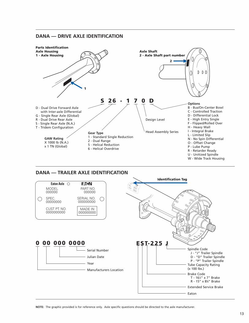
DANA — DRIVE AXLE IDENTIFICATION
DANA — TRAILER AXLE IDENTIFICATION
1
2
Parts IdentificationAxle Housing Axle Shaft1 - Axle Housing 2 - Axle Shaft part number
S 26 - 1 7 0 D
0 00 000 0000Serial Number
Julian Date
Year
Manufacturers Location
OptionsB - Bus/On-Center BowlC - Controlled TractionD - Differential LockE - High Entry SingleF - Flipped/Rolled OverH - Heavy WallI - Integral BrakeL - Limited SlipN - No Spin DifferentialO - Offset ChangeP - Lube PumpR - Retarder ReadyU - Unitized SpindleW - Wide Track Housing
Design Level
Head Assembly SeriesGear Type1 - Standard Single Reduction2 - Dual Range5 - Helical Reduction6 - Helical Overdrive
GAW RatingX 1000 lb (N.A.)x 1 TN (Global)
D - Dual Drive Forward Axle with Inter-axle Differential
G - Single Rear Axle (Global)R - Dual Drive Rear AxleS - Single Rear Axle (N.A.)T - Tridem Configuration
EST-225 JSpindle Code
J - “J” Trailer SpindleD - “D” Trailer SpindleP - “P” Trailer Spindle
Tube Capacity Rating(x 100 lbs.)
Brake CodeT - 161⁄2" x 7" BrakeR - 15” x 85⁄8” Brake
Extended Service Brake
Eaton
NOTE: The graphic provided is for reference only. Axle specific questions should be directed to the axle manufacturer.

14
HENDRICKSON INTERNATIONAL — TRAILER AXLE IDENTIFICATION
Model: VANTRAAX.5836Description: HKANT40K 165RH 77USHD MA X7SH
Model: VANTRAAX.2157Description: HKAT 50K 16RH 71NST QD X7SHD
Model: INTRAAX.2597Description: AAT 23K 14RH C77USST 7S
Model: INTRAAX.3598Description: AAL 30K 9RH 71PST
LOAD RATINGSThe load/capacity rating of a given axle is determined by the axle
housing strength, bearing capacity, and hub capacity. For some ultra-
lightweight axles, the reduced axle housing thickness may be the weak
link, but usually it is the bearings or hub that will be the limiting factor.
These axles and components are typically designed under the
assumption that the action line of the tire load is located between
the two bearings. This is typically found with dual tire mounting
or with single tires with very low outset wheels with the axle
rating being similarly determined.
If wheels with greater outset are used, the resulting
cantilever loading may require lower ratings for some of the
axle components. The level of de-rating and the implications
thereof are determined by the axle manufacturer, so they should
be consulted prior to fitment of outset single wheels.
Prior to contacting the axle manufacturer, you should consult
the axle identification tag to obtain the following information:
Axle Manufacturer
Manufacturers Model #
Axle Serial Number
Axle Capacity
Information on actual operational axle loading (as opposed to
rated load) is crucial, since the axle manufacturer may recommend
de-rating the axle below the vehicle manufacturer’s GAWR.
With this data in hand, contact the particular axle
manufacturer at the numbers listed below for specific
application information.
ArvinMeritor — 248-535-5560
Dana Spicer — 800-826-4357
Hendrickson International — 800-455-0043 or 800-RIDEAIR
U - HUS Spindle
N - N Spindle
U - HUS Spindle
P - P Spindle
NOTE: The graphic provided is for reference only. Axle specific questions should be directed to the axle manufacturer.
WheelOutset
Actual Track Width
WheelInset
WheelOutset
Actual Track Width
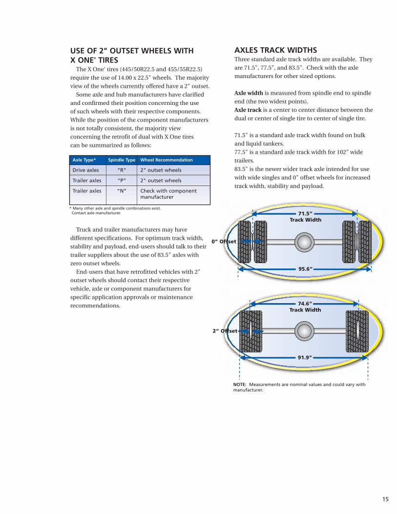
AXLES TRACK WIDTHSThree standard axle track widths are available. They
are 71.5", 77.5", and 83.5". Check with the axle
manufacturers for other sized options.
Axle width is measured from spindle end to spindle
end (the two widest points).
Axle track is a center to center distance between the
dual or center of single tire to center of single tire.
71.5" is a standard axle track width found on bulk
and liquid tankers.
77.5" is a standard axle track width for 102" wide
trailers.
83.5" is the newer wider track axle intended for use
with wide singles and 0" offset wheels for increased
track width, stability and payload.
USE OF 2" OUTSET WHEELS WITH X ONE® TIRES
The X One® tires (445/50R22.5 and 455/55R22.5)
require the use of 14.00 x 22.5" wheels. The majority
view of the wheels currently offered have a 2" outset.
Some axle and hub manufacturers have clarified
and confirmed their position concerning the use
of such wheels with their respective components.
While the position of the component manufacturers
is not totally consistent, the majority view
concerning the retrofit of dual with X One tires
can be summarized as follows:
Truck and trailer manufacturers may have
different specifications. For optimum track width,
stability and payload, end-users should talk to their
trailer suppliers about the use of 83.5" axles with
zero outset wheels.
End-users that have retrofitted vehicles with 2"
outset wheels should contact their respective
vehicle, axle or component manufacturers for
specific application approvals or maintenance
recommendations.
15
Axle Type* Spindle Type Wheel Recommendation
Drive axles “R” 2" outset wheels
Trailer axles “P” 2" outset wheels
Trailer axles “N” Check with componentmanufacturer
* Many other axle and spindle combinations exist. Contact axle manufacturer.
NOTE: Measurements are nominal values and could vary withmanufacturer.
74.6”Track Width
91.9”
71.5”Track Width
2” Offset
95.6”
0” Offset

The best way to determine what type of spindle
may be fitted to a given axle is to reference the axle
ID data plate affixed to the axle or the suspension ID
tag as described in on Pages 12-14. The following
photos are display actual tag placements.
A quick rule of thumb is to measure the hub cap.
N-type is usually ~4.5" and the P-type is usually ~6.0".
16
SPINDLESThere are three main spindle types you will encounter
when retrofitting X One® tires: “N”, “P” and “R”.
N-TYPE SPINDLES (TAPERED)N-type spindles are tapered to the outboard end and
utilizes a smaller outboard bearing and a larger inboard
bearing.
P-TYPE SPINDLES (STRAIGHT)P-type is a parallel spindle design (straight shaft) and
utilizes the same sized bearings inboard and outboard.
This is generally a heavier duty axle end.
R-TYPE SPINDLESR-type is a drive axle spindle configuration. The
R-type spindle for drive axles is typically straight with
bearings of nearly the same size.
Tag Placement
Tag Placement
N-Type Spindle
P-Type Spindle
Outer bearing smaller than inner bearing.
Outer and inner bearings the same size.
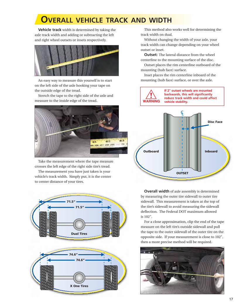
This method also works well for determining the
track width on dual.
Without changing the width of your axle, your
track width can change depending on your wheel
outset or inset.
Outset: The lateral distance from the wheel
centerline to the mounting surface of the disc.
Outset places the rim centerline outboard of the
mounting (hub face) surface.
Inset places the rim centerline inboard of the
mounting (hub face) surface, or over the axle.
Overall width of axle assembly is determined
by measuring the outer tire sidewall to outer tire
sidewall. This measurement is taken at the top of
the tire’s sidewall to avoid measuring the sidewall
deflection. The Federal DOT maximum allowed
is 102".
For a close approximation, clip the end of the tape
measure on the left tire’s outside sidewall and pull
the tape to the outer sidewall of the outer tire on the
opposite side. If your measurement is close to 102",
then a more precise method will be required.
Vehicle track width is determined by taking the
axle track width and adding or subtracting the left
and right wheel outsets or insets respectively.
An easy way to measure this yourself is to start
on the left side of the axle hooking your tape on
the outside edge of the tread.
Stretch the tape to the right side of the axle and
measure to the inside edge of the tread.
Take the measurement where the tape measure
crosses the left edge of the right side tire’s tread.
The measurement you have just taken is your
vehicle’s track width. Simply put, it is the center
to center distance of your tires.
17
OVERALL VEHICLE TRACK AND WIDTH
If 2" outset wheels are mountedbackwards, this will significantly reduce track width and could affectvehicle stability.
Outboard Inboard
OUTSET
71.5”
74.6”
74.6”
71.5”
Dual Tires
X One Tires
Disc Face
18
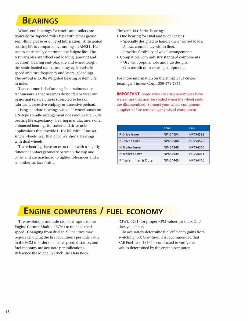
Wheel-end bearings for trucks and trailers are
typically the tapered roller type with either grease,
semi-fluid grease or oil level lubrication. Anticipated
bearing life is compared by running an ANSI L-10a
test to statistically determine the fatigue life. The
test variables are wheel end loading (amount and
location), bearing end-play, tire and wheel weight,
tire static loaded radius, and duty cycle (vehicle
speed and turn frequency and lateral g loading).
The output is L-10a Weighted Bearing System Life
in miles.
The common belief among fleet maintenance
technicians is that bearings do not fail or wear out
in normal service unless subjected to loss of
lubricant, excessive endplay or excessive preload.
Using standard bearings with a 2" wheel outset on
a N-type spindle arrangement does reduce the L-10a
bearing life expectancy. Bearing manufacturers offer
enhanced bearings for trailer and drive axle
applications that provide L-10a life with 2" outset
single wheels near that of conventional bearings
with dual wheels.
These bearings have an extra roller with a slightly
different contact geometry between the cup and
cone, and are machined to tighter tolerances and a
smoother surface finish.
BEARINGSTimken’s 454-Series bearings:
• One bearing for Dual and Wide Singles
– Specially designed to handle the 2" outset loads.
– Allows consistency within fleet.
– Provides flexibility of wheel arrangements.
• Compatible with industry standard components
– Use with popular axle and hub designs.
– Can retrofit onto existing equipment.
For more information on the Timken 454-Series
bearings: Timken Corp.: 330-471-7375.
IMPORTANT: Some wheel bearing assemblies have
warranties that may be voided when the wheel ends
are disassembled. Contact your wheel component
supplier before removing any wheel component.
Cone Cup
R Drive Inner NP454594 NP454592
R Drive Outer NP454580 NP454572
N Trailer Inner NP454248 NP454210
N Trailer Outer NP454049 NP454011
P Trailer Inner & Outer NP454445 NP454410
Tire revolutions and axle ratio are inputs to the
Engine Control Module (ECM) to manage road
speed. Changing from dual to X One® tires may
require changing the tire revolutions per mile value
in the ECM in order to ensure speed, distance, and
fuel economy are accurate per indications.
Reference the Michelin Truck Tire Data Book
(MWL40731) for proper RPM values for the X One®
tires you chose.
To accurately determine fuel efficiency gains from
switching to X One® tires, it is recommended that
SAE Fuel Test J1376 be conducted to verify the
values determined by the engine computer.
ENGINE COMPUTERS / FUEL ECONOMY

19
AIR INFLATION AND PRESSURE MONITORING SYSTEMSProper inflation pressure is critical to the overall
performance of all tires on the road today.
Today’s radial truck tires will lose less than one psi
per month due to air migration through the casing.
Faster loss of inflation can only occur in
conjunction with some sort of leak in the wheel,
valve stem or tire structure. Whatever the source of
the leak, it must be identified and corrected to avoid
further damage to that component possibly leading
to a compromise in safety.
AVAILABLE SYSTEMSTire pressure monitoring systems have been
legislated for all vehicles by the TREAD Act. The
implementation schedule is in place for vehicles with
GVW below 10,000#, but is yet to be determined for
heavier vehicles. The existing systems “read” the
pressure in the tire via a sensor mounted on the valve
stem, wheel or mounted inside the tire. Sensors that
are not physically inside the tire/wheel cavity cannot
accurately measure the internal air temperature, so
are they unable to determine the “cold inflation
pressure.” In addition, external sensors probably
require additional air line plumbing that creates
additional potential leak points.
Monitoring systems may provide either pressure
data or a low pressure warning. The pressure data
may be “hot” or “cold” pressure, so it is necessary
that the person viewing that data fully understand
which pressure is reported and what it means. Low
pressure alarm only systems alert the driver when
the pressure in a particular tire (or pair of dual tires
if linked together) is below some fleet chosen
minimum. This value may be preset by the sensor
supplier or may be programmable by the fleet. Tire
manufacturers, through the Rubber Manufacturers
Association, have agreed that a tire must be
considered flat if the inflation pressure is 20% or
more below the pressure recommended for that tire.
A flat tire must be removed from the rim, thoroughly
examined, and properly repaired prior to re-inflation
and use.
Some systems provide inflation pressure
information at the sensor site only, so the driver
must walk around the vehicle to gather/view either
the pressure reading or low pressure warning. Other
systems transmit the information to the cab where it
may be viewed by the driver, and/or sent to a central
facility if the vehicle is tracked by satellite
Inflation-only systems are designed to add air
to maintain a preset pressure, but, do not have the
ability to reduce the pressure should a tire be over
inflated. These systems can account for slower leaks
(determined by the air delivery capacity of the
system) and provide some warning to the driver
when the system is energized (adding air) or when it
cannot keep up with the leak. Almost all inflation-
only systems use air from the vehicle air brake
system, so they will be limited in max pressure and
available volumetric flow. In addition, these systems
are usually only applied to trailer axles where
plumbing the air supply line is easier.
Tire inflation systems may add air to tires
determined to be below some fleet chosen pressure.
Some Central Tire Inflation Systems (CTIS) will also
allow pressure reduction on any tire on the vehicle
to maintain some given pressure level. Such systems
are rather expensive and more often used only on
specialty vehicles (Military, emergency response,
National parks, etc.)
A key factor in any monitoring or inflation system
is determining whether the target or set pressure is a
“hot” pressure or a “cold” one. This should be
discussed with your tire manufacturer’s
representative.
Air inflation systems are notguarantees against low pressuresituations. All vehicles should stillbe subject to pre-trip inspectionsand systems operation should beverified routinely.

20
THE USE OF PRESSURE MONITORING AND INFLATION SYSTEMS WITH MICHELIN TRUCK TIRES
In view of the increasing visibility and promotion
for the use of pressure monitoring and/or inflation
systems, Michelin takes the following position:
• Michelin has not and cannot test every system
that is being marketed/manufactured for
effectiveness, performance and durability.
• The use of these systems does not nullify the
Michelin truck tire warranty unless it is
determined that the system somehow contributed
to the failure or reduced performance of the tire.
• Proper air pressure maintenance is important for
the optimal performance of the tires so it is
important to make sure the system can maintain
the pressures needed and/or can detect accurately
when the pressures are outside of the normal
operating range(s) for the loads being carried.
• It is the responsibility of the system manufacturerto ensure that the tires are inflated as rapidly aspossible to the optimal operating pressure inorder to prevent internal damage to the tires.
• Michelin strongly urges the customer to put the
responsibility on the system’s manufacturer to
prove and support their claims.
In addition to the foregoing, please refer to the
Michelin® Truck Tire Warranty Manual (MWE40021)
for a general discussion of what is and is not covered
by the warranty.
CENTRAL TIRE INFLATION SYSTEMSON TRAILERS AND MISSED NAIL HOLES
Central tire inflation (“CTI”) systems on trailers
can sometime make slow leaks caused by nails or
other small objects penetrating the crown area of the
tire undetectable. A slow leak can be compensated
for by the air inflation system. The warning light of
the “CTI” system will only come on if the pressure in
the tire drops below a certain percent (usually 10%)
of the regulated preset pressure. Even when the
pressure drops below this point, the light will go off
if the system is able to restore and maintain the
preset pressure.
The tires on trailers with “CTI" systems should
be visually inspected before and after use and any
imbedded objects removed and the tire repaired.
An undetected imbedded object remaining in the
tire can allow air infiltration and consequently a
possible catastrophic failure of the sidewall.
TRUCK TYPE BY WEIGHT CLASS
21
VAN
DOUBLES
LIQUID TANK
DRY BULK
LOGGER
PLATFORM
SPREAD AXLE
DROP FRAME
DUMP
REEFER
DEEP DROP
AUTO TRANSPORTER
DOLLY
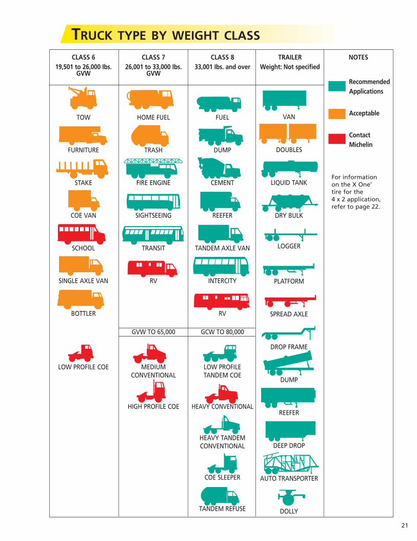
CLASS 6 CLASS 7 CLASS 8 TRAILER NOTES19,501 to 26,000 Ibs. 26,001 to 33,000 Ibs. 33,001 Ibs. and over Weight: Not specified
GVW GVW
TOW HOME FUEL FUEL
FURNITURE TRASH DUMP
STAKE FIRE ENGINE CEMENT
COE VAN SIGHTSEEING REEFER
SCHOOL TRANSIT TANDEM AXLE VAN
SINGLE AXLE VAN RV INTERCITY
BOTTLER RV
GVW TO 65,000 GCW TO 80,000
LOW PROFILE COE MEDIUM LOW PROFILE CONVENTIONAL TANDEM COE
HIGH PROFILE COE HEAVY CONVENTIONAL
HEAVY TANDEM CONVENTIONAL
COE SLEEPER
TANDEM REFUSE
RecommendedApplications
Acceptable
ContactMichelin
For informationon the X One®
tire for the4 x 2 application,refer to page 22.

22
X ONE® TIRES IN 4 x 2 APPLICATIONSSingle tire fitments have proven themselves in
numerous North American applications and are
expected to grow in popularity with fleets. Single
tires are, of course, the norm on steer axles, and
are proven, valid solutions on trailers and on
driven axles of tandem axle (6 x 4) tractors.
However, recent handling studies indicate that for
certain types of commercial single axle (4 x 2)
tractors pulling trailers, the vehicle dynamics are
such that handling may be degraded in the event
of a tire failure when fitted with singles. No other
vehicle types or wheel positions have shown any
further handling issues with single tires.
In the interest of caution, Michelin recommends
that single axle (4 x 2) tractors fitted with X One®
tires on the driven axles always be equipped
with an Electronic Stability Program (ESP).
Without an ESP on the 4 x 2 tractor, four tires are
recommended across the driven axle rather than
two tires. Once again, no other vehicle types are
affected by this recommendation.
Please note: This does not change Michelin's long-standing
position that all types of motor vehicles can be
controlled in the event of a rapid air loss under
normal, legal driving conditions. Michelin
maintains that vehicle control in rapid air loss
situations is a matter of driver education and
training.
Top Related