


Languages
Pages
Legal

Slide -1Why We Need EM
Bogatin Enterprises, a LeCroy Company 2012 www.beTheSignal.com
Why You Need Electromagnetics for Signal
Integrity Analysis – Sometimes(presented at DesignCon 2011 with Stephen Hall, Olufemi(Femi) Oluwafemi, Jeff Loyer
Intel Corporation)
Dr. Eric Bogatin,
Signal Integrity Evangelist,
Bogatin Enterprises
Copies of this presentation are available on
www.beTheSignal.com
5/1/2012
James Clerk Maxwell (1831-1879) George Simon Ohm (1789-1854)
Slide -2Why We Need EM
Bogatin Enterprises, a LeCroy Company 2012 www.beTheSignal.com
Overview
• Two world views
Circuit elements
Electromagnetics
• Success stories
Transmission lines and circuits
Real capacitors for the PDN
• Examples where circuit model view is not accurate enough
FEXT
PDN design: does location matter?
Return current through planes
Slide -3Why We Need EM
Bogatin Enterprises, a LeCroy Company 2012 www.beTheSignal.com
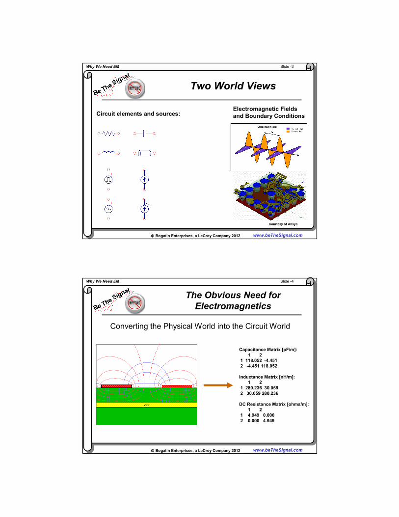
Two World Views
Circuit elements and sources:Electromagnetic Fields
and Boundary Conditions
Courtesy of Ansys
Slide -4Why We Need EM
Bogatin Enterprises, a LeCroy Company 2012 www.beTheSignal.com
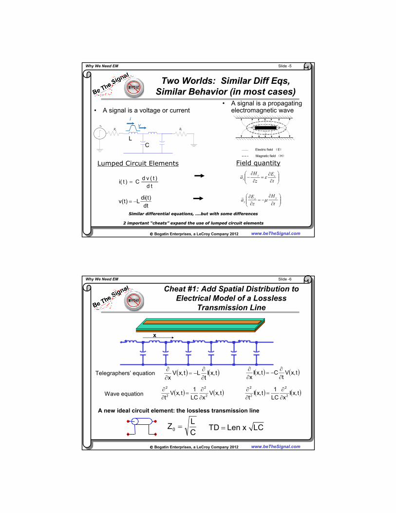
The Obvious Need for
Electromagnetics
Converting the Physical World into the Circuit World
Capacitance Matrix [pF/m]:
1 2
1 118.052 -4.451
2 -4.451 118.052
Inductance Matrix [nH/m]:
1 2
1 280.236 30.059
2 30.059 280.236
DC Resistance Matrix [ohms/m]:
1 2
1 4.949 0.000
2 0.000 4.949
Slide -5Why We Need EM
Bogatin Enterprises, a LeCroy Company 2012 www.beTheSignal.com
Two Worlds: Similar Diff Eqs,
Similar Behavior (in most cases)
• A signal is a voltage or current
∂
∂−=
∂∂
t
H
z
Ea
yx
y µ
∂∂
=∂
∂−
t
E
z
Ha xy
x ε
di(t)v(t) L
dt= −
Field quantityLumped Circuit Elements
LC
RtRs
vs
i
v
Electric field ( E )
Magnetic field ( H )
• A signal is a propagating electromagnetic wave
Similar differential equations, Similar differential equations, …….but with some differences.but with some differences
2 important 2 important ““cheatscheats”” expand the use of lumped circuit elementsexpand the use of lumped circuit elements
d v ( t )i( t ) C
d t=
Slide -6Why We Need EM
Bogatin Enterprises, a LeCroy Company 2012 www.beTheSignal.com
Cheat #1: Add Spatial Distribution to
Electrical Model of a Lossless
Transmission Line
( ) ( )t,xIt
Lt,xVx ∂
∂−=
∂∂ ( ) ( )t,xV
tCt,xI
x ∂∂
−=∂∂
( ) ( )t,xVxLC
1t,xV
t 2
2
2
2
∂∂
=∂∂ ( ) ( )t,xI
xLC
1t,xI
t 2
2
2
2
∂∂
=∂∂
Telegraphers’ equation
Wave equation
C
LZ0 =
x
A new ideal circuit element: the lossless transmission line
TD Len x LC=

Slide -7Why We Need EM
Bogatin Enterprises, a LeCroy Company 2012 www.beTheSignal.com
Circuit Model View is Incredibly
Successful!
V1
V2
V3V4
Slide -8Why We Need EM
Bogatin Enterprises, a LeCroy Company 2012 www.beTheSignal.com
Cheat #2: How Current Flows in
Transmission lines
How does current flow?
Leads to miss conception of how current flows in a transmission line
Our Elementary School View of
Current Flow
Slide -9Why We Need EM
Bogatin Enterprises, a LeCroy Company 2012 www.beTheSignal.com
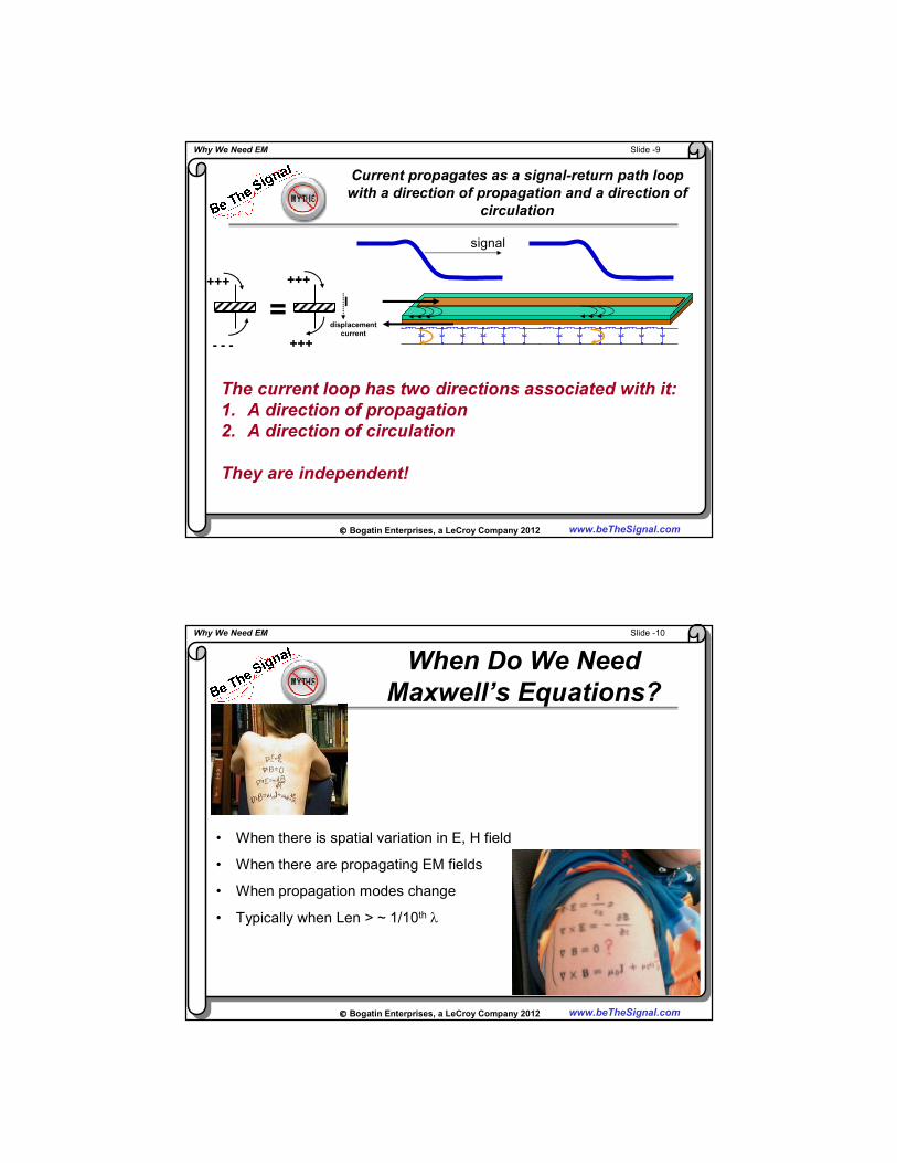
Current propagates as a signal-return path loop
with a direction of propagation and a direction of
circulation
signal
The current loop has two directions associated with it:
1. A direction of propagation
2. A direction of circulation
They are independent!
+++
=
+++
- - - +++
I
displacement
current
Slide -10Why We Need EM
Bogatin Enterprises, a LeCroy Company 2012 www.beTheSignal.com
When Do We Need
Maxwell’s Equations?
• When there is spatial variation in E, H field
• When there are propagating EM fields
• When propagation modes change
• Typically when Len > ~ 1/10th λ
Slide -11Why We Need EM
Bogatin Enterprises, a LeCroy Company 2012 www.beTheSignal.com
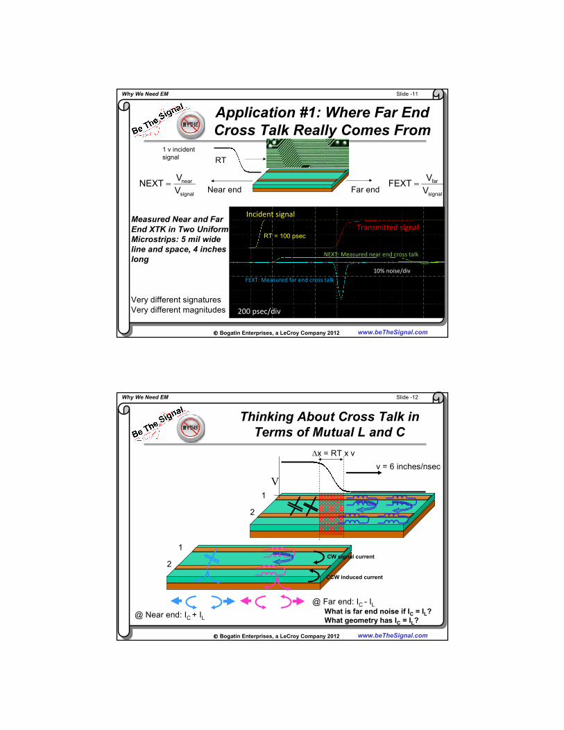
Application #1: Where Far End
Cross Talk Really Comes From
Very different signatures
Very different magnitudes
RT
1 v incident
signal
Near endsignal
near
V
VNEXT =
Far endsignal
far
V
VFEXT =
Incident signal
Transmitted signal
NEXT: Measured near end cross talk
FEXT: Measured far end cross talk
200 psec/div
10% noise/div
RT = 100 psec
Measured Near and Far
End XTK in Two Uniform
Microstrips: 5 mil wide
line and space, 4 inches
long
Slide -12Why We Need EM
Bogatin Enterprises, a LeCroy Company 2012 www.beTheSignal.com
Thinking About Cross Talk in
Terms of Mutual L and C
1
2
V
v = 6 inches/nsec
∆x = RT x v
1
2CW signal current
CCW induced current
@ Near end: IC + IL
@ Far end: IC - ILWhat is far end noise if IC = IL?
What geometry has IC = IL?

Slide -13Why We Need EM
Bogatin Enterprises, a LeCroy Company 2012 www.beTheSignal.com
Eliminate FEXT with StriplineMeasured at Far end, Near end terminated, TDT end Open
Differences:
Far end cross talk
in microstrip:
IL > IC
No far end cross
talk in stripline:
IL = IC
MicrostripStripline
TDR open50 Ohms Far end noise
TDR response
Noise response
Why?
Slide -14Why We Need EM
Bogatin Enterprises, a LeCroy Company 2012 www.beTheSignal.com
An Alternative Way of Thinking
About Far End Cross Talk
Odd mode Even mode
500 psec/div
TCC21
TDD21
Which signal travels faster?

Slide -15Why We Need EM
Bogatin Enterprises, a LeCroy Company 2012 www.beTheSignal.com
An Alternative Way of Thinking
About Far End Cross Talk
= ½ ½+
What comes out?
Far end cross talk is really due to the difference in speed
between a differential and common signal
What is the far end noise expected in stripline?
Slide -16Why We Need EM
Bogatin Enterprises, a LeCroy Company 2012 www.beTheSignal.com
Microstrip vs. Stripline
1. No difference in speed between diff and comm signal
2. No far end cross talk
SCC21
SDD21
SCC21
SDD21
Odd mode Even mode

Slide -17Why We Need EM
Bogatin Enterprises, a LeCroy Company 2012 www.beTheSignal.com
1E7 1E81E6 2E8
1E-1
1
1E-2
1E1
freq, Hz
Impedance,
Ohm
s
Application #2:
Capacitors and Planes
Sample courtesy of X2Y
Measured Impedance of Real, 220 nF,
0603 MLCC Capacitor
Slide -18Why We Need EM
Bogatin Enterprises, a LeCroy Company 2012 www.beTheSignal.com
1E7 1E81E6 2E8
1E-1
1
1E-2
1E1
freq, Hz
Impedance,
Ohm
s
Behavior of Real, 220 nF,
0603 MLCC Capacitor: fitting RLC Model
Sample courtesy of X2Y
Measured
impedance
Simulated
impedance
C = 180 nF
ESR = 0.017 Ω
ESL = 1.3 nH
Note: ESL is not intrinsic to the capacitorNote: ESL is not intrinsic to the capacitor-- related to mountingrelated to mounting1111
1CxESL
MHz160
CxESL2
1SRF =
π=
CESL
ESR

Slide -19Why We Need EM
Bogatin Enterprises, a LeCroy Company 2012 www.beTheSignal.com
1E7 1E81E6 2E8
1E-1
1
1E-2
1E1
freq, Hz
Impedance,
Ohm
s
X2Y Capacitor Example
220nF X2Y
C = 180 nF
L = 0.42 nH
R = 0.012 Ohms
X2Y capacitors are an important low inductance alternativeX2Y capacitors are an important low inductance alternative
Measured
Simulated RLC model
C
L
R
Like 4 capacitors in parallel
0603 MLCC
X2Y
Sample courtesy of X2Y
Slide -20Why We Need EM
Bogatin Enterprises, a LeCroy Company 2012 www.beTheSignal.com
Unlike Real Estate, Does Position
Matter with Capacitors?
4 capacitors,
0.1uF, ESL =
3 nH, 2 in x 2
inch cavity
Does position matter?When cavity spreading inductance is small, and
caps have high ESL, cavity is transparent, position
does not matter much

Slide -21Why We Need EM
Bogatin Enterprises, a LeCroy Company 2012 www.beTheSignal.com
The Other Extreme:
Thick Cavity, Low ESL Capacitors
4 capacitors,
0.1uF, ESL =
0.5 nH, 2 in x
2 inch cavity
Does position matter?When cavity spreading inductance is large, and caps have small
ESL, cavity is NOT transparent, position does matter
Slide -22Why We Need EM
Bogatin Enterprises, a LeCroy Company 2012 www.beTheSignal.com
Application #3:
Return Current Through Two Planes
• When the return plane changes, return current is injected into the plane cavity
Current travels like a radial wave through the impedance of the plane-plane cavity
This is the most important way high frequency noise is injected into the board planes
• Set up:
50 ohm microstrip top and bottom
30 mil thick dielectric between the planes
10 inch x 10 inch board
1 v signal, 20 mA at 0.2 nsec rise time
Simulated voltage between the planes with HyperLynx/PI (20 mV full scale ( 2%)
Slide -23Why We Need EM
Bogatin Enterprises, a LeCroy Company 2012 www.beTheSignal.com
How to Minimize the Switching Noise in
Signal Vias Changing Return Planes?
“a lot is good, more is better and too many is just right”
- Frank SchonigAdd an adjacent return via
Add 4 adjacent return vias
HyperLynx 8.0
Slide -24Why We Need EM
Bogatin Enterprises, a LeCroy Company 2012 www.beTheSignal.com
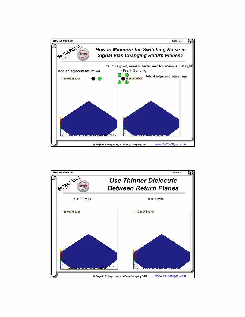
Use Thinner Dielectric
Between Return Planes
h = 30 mils h = 3 mils
HyperLynx 8.0

Slide -25Why We Need EM
Bogatin Enterprises, a LeCroy Company 2012 www.beTheSignal.com
The Use of Potential Return Vias
Drives Return Plane Selection
• Voltage on return plane has no impact on the impedance of the signal line
• Return plane selection is all about the via design
• Add return via adjacent to each signal via, as close to signal via as practical
1
2
3
4
Second best return plane selection
signal
1
2
3
4
Best return plane selection
signal
As fall back: use thin dielectric between all adjacent planes, add low L DC-
blocking caps between changing return planes: limited value with shorter RT
Slide -26Why We Need EM
Bogatin Enterprises, a LeCroy Company 2012 www.beTheSignal.com
“Sometimes a lie tells more of the
truth than the truth” – Francis Low
• “Engineering is the art of approximation”
• Use the approach that gets you “an acceptable answer fastest”
• For most signal integrity problems, voltage, current and circuits is just fine- provided you think about wave propagation of signals!
• But, some effects are inherently electromagnetic field related and can’t be approximated by voltage, current and circuits:
How geometry and material properties affect circuit element values
Electromagnetic interactions with materials- conductors and dielectrics
Distributed electrical properties of interconnects
EMI and radiation effects
Coupling between waveguides
Signal transmission when the propagation mode changes
• Electromagnetics is in your future.
• Embrace Maxwell’s Equations

Slide -27Why We Need EM
Bogatin Enterprises, a LeCroy Company 2012 www.beTheSignal.com
For More Information
www.BeTheSignal.com
SI Library
Webinars, feature articles, presentations,
hands on labs
Class schedules
Published by Prentice Hall, 2009
Blog: www.beTheSignal.com/blog
@beTheSignal
Top Related